Sercomm RC8322 Wireless Network Camera User Manual RC8322 Manual v1 0828
Sercomm Corporation Wireless Network Camera RC8322 Manual v1 0828
UserManual.wiki
>
Sercomm
>
RC8322 User Manual
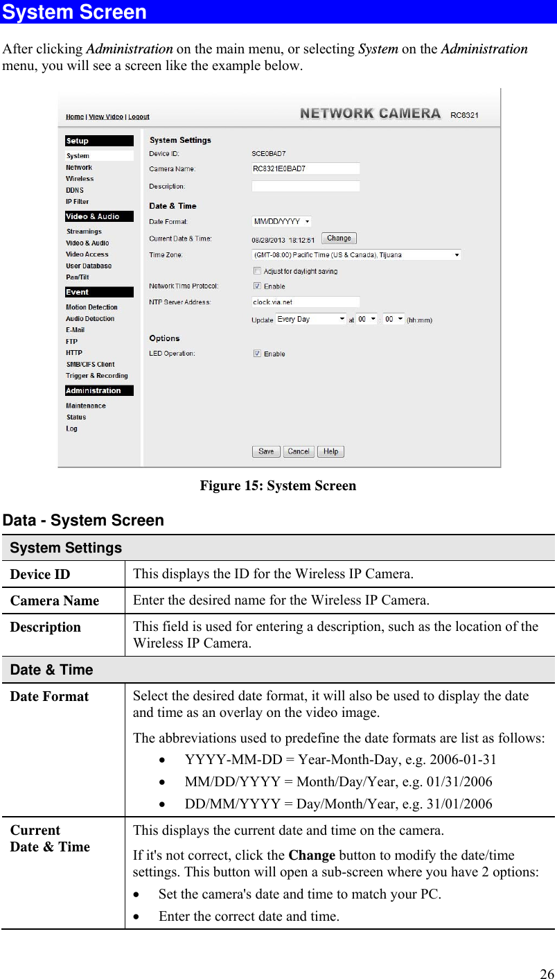
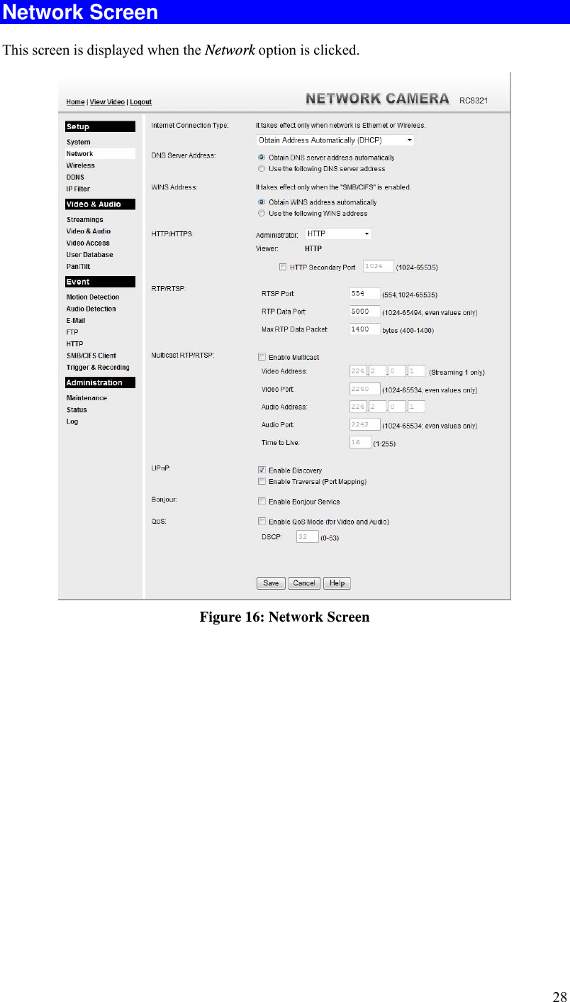
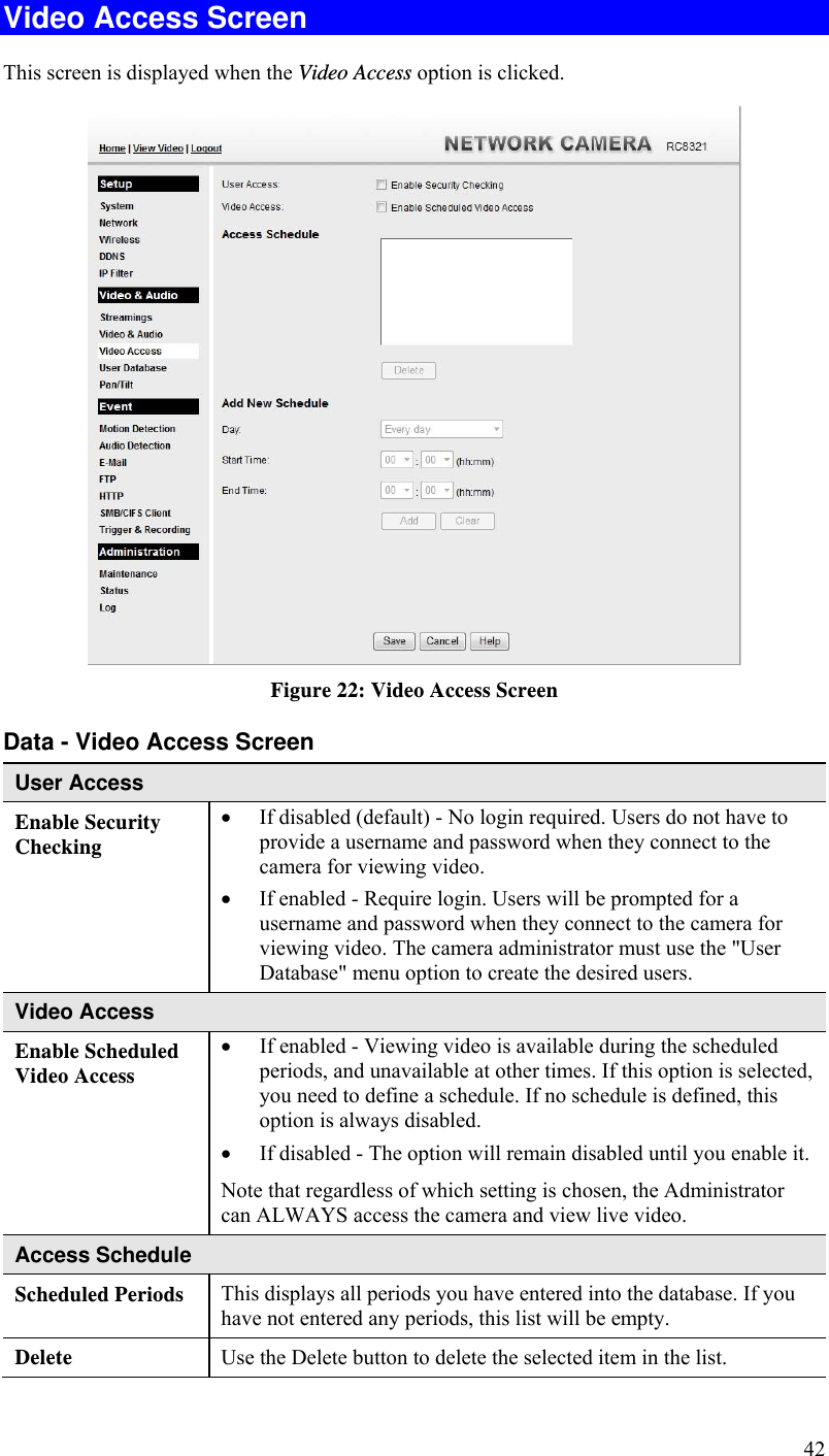
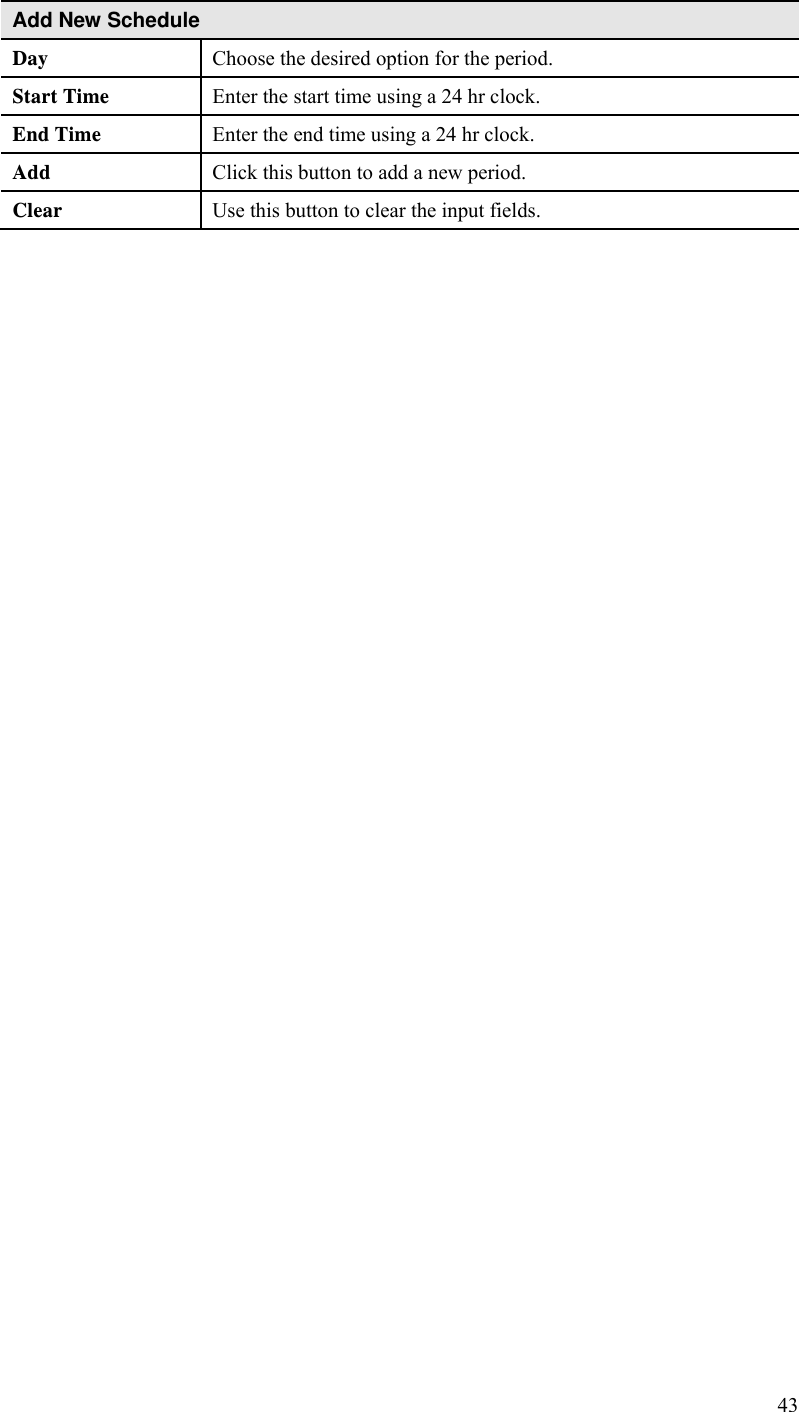
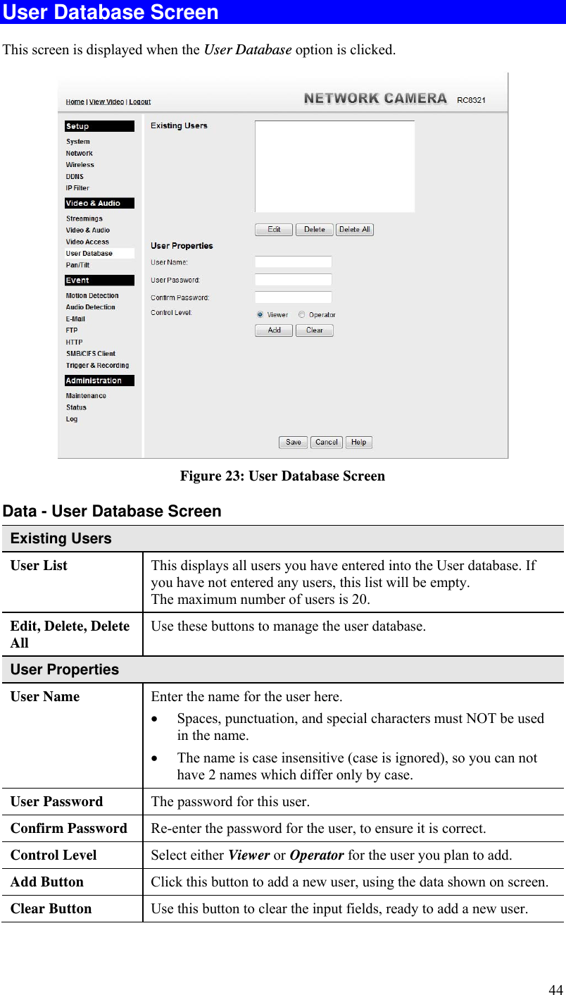
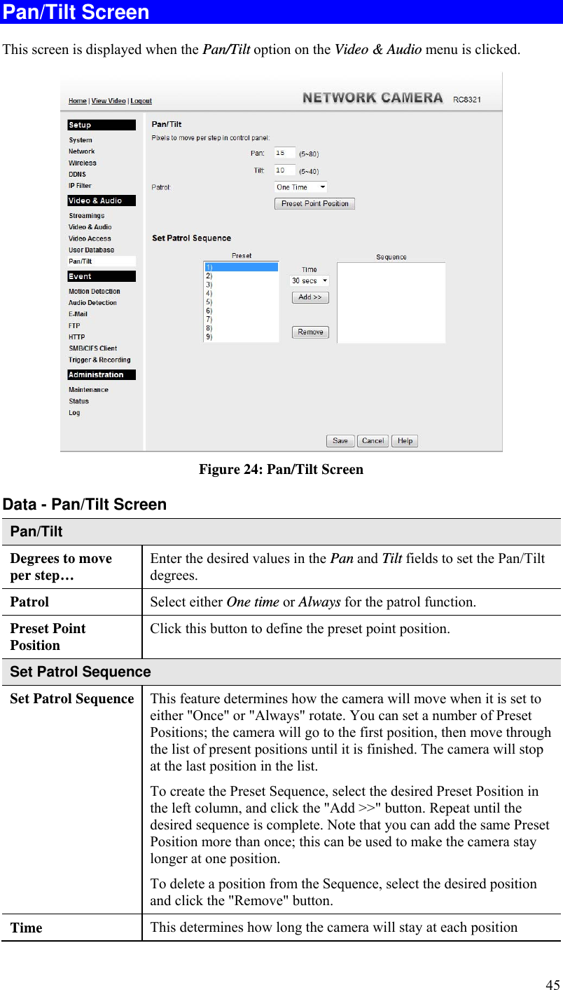
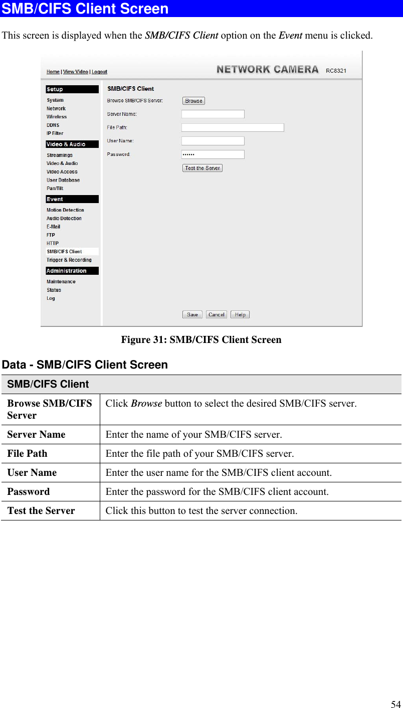
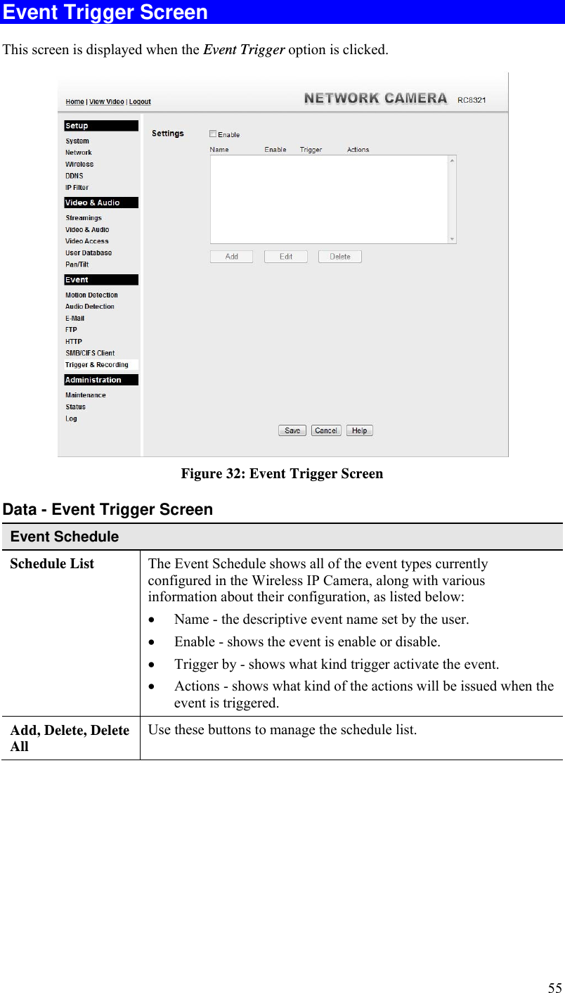
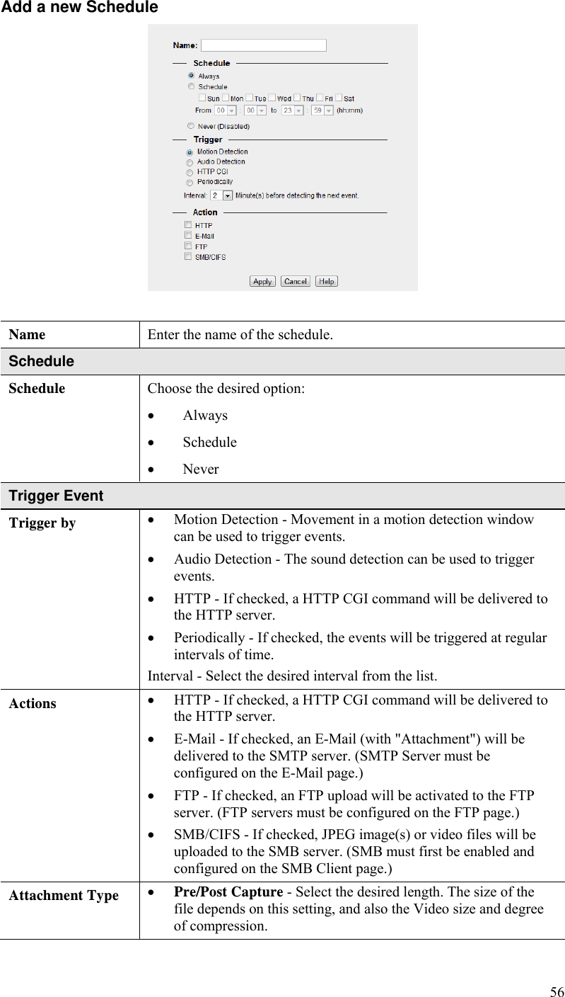
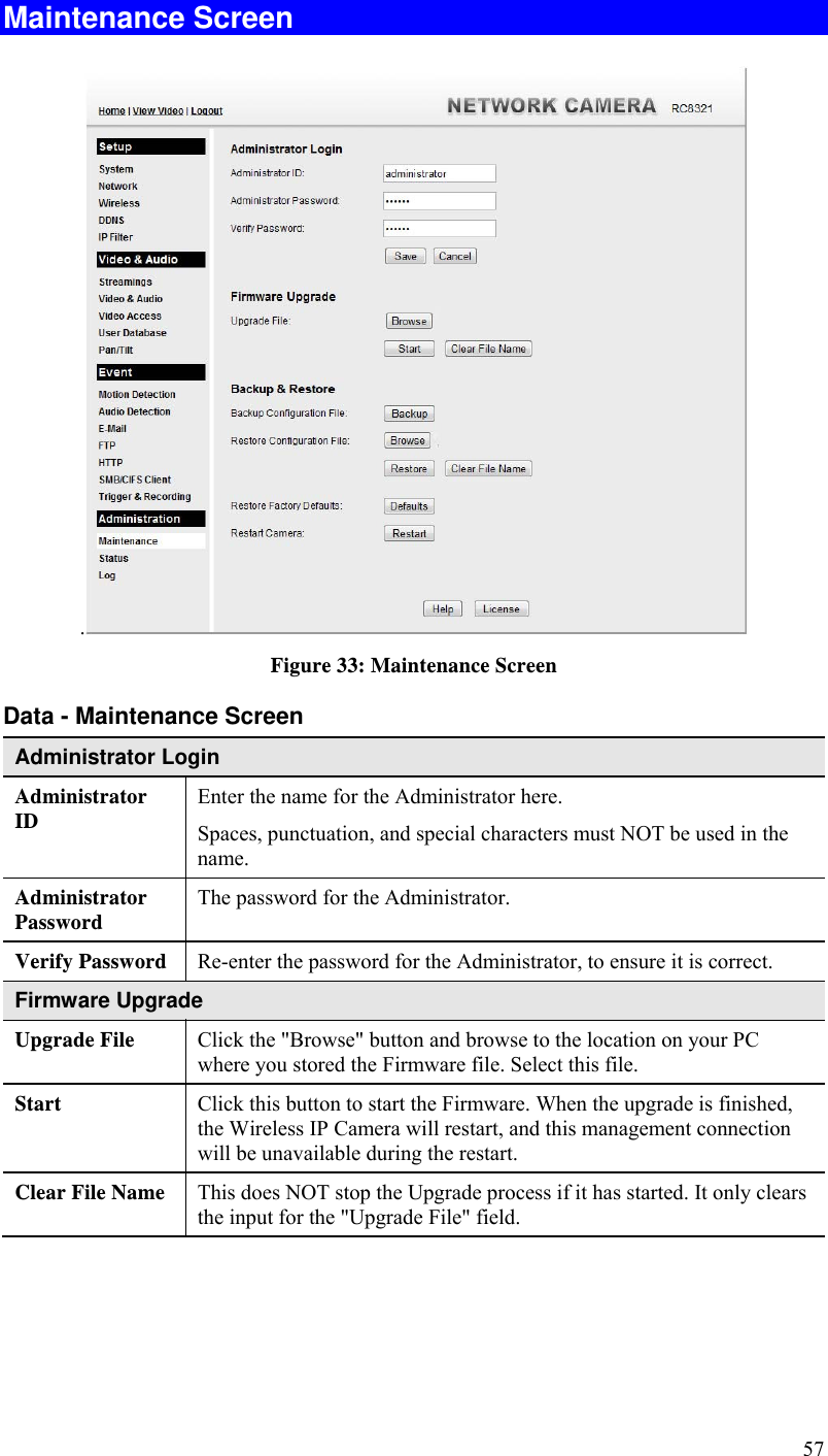
Users manual
Navigation menu
Upload a User Manual
Namespaces
Wiki Guide
HTML
PDF
Info
Views
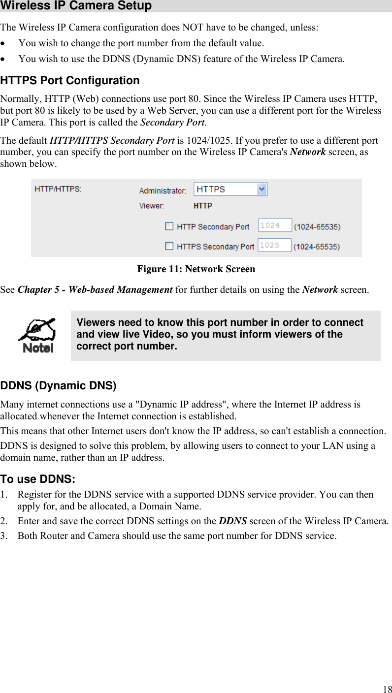
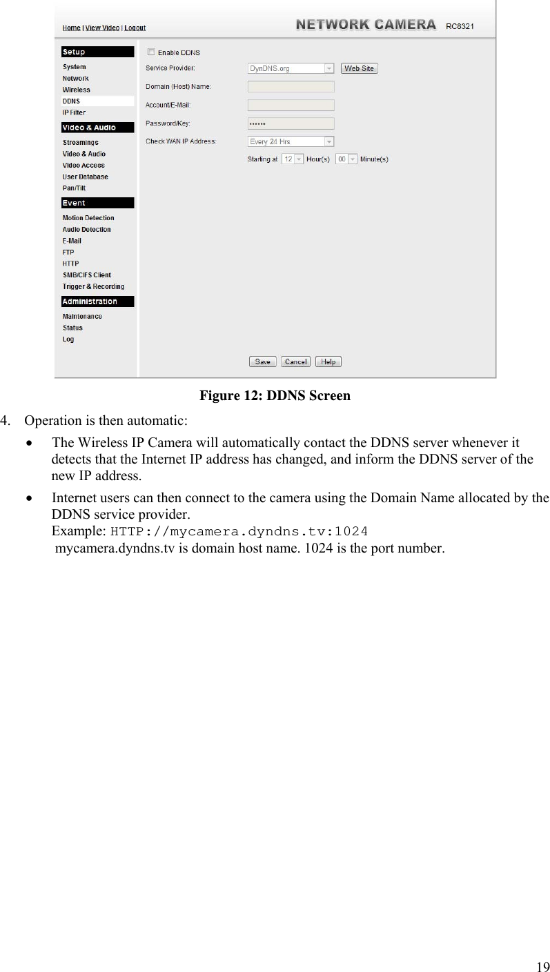
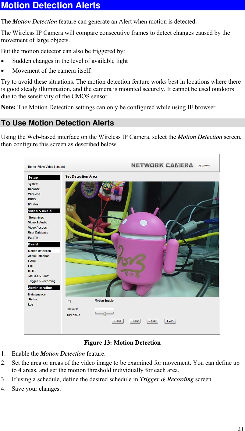
User Manual
Discussion / Help
Navigation