Sercomm RP101V2 WiFi Repeater User Manual RP101v2 Manual
Sercomm Corporation WiFi Repeater RP101v2 Manual
Sercomm >
User manual

RP101v2
Wireless Repeater
Manual Guide
Page 1
Introduction
Overview
The RP101v2 is Wireless Repeater, you can use this device to ex-
tend your existing Wireless network.
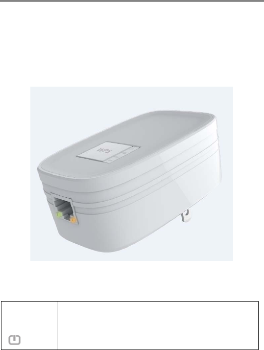
Physical Details
Figure 1: RP101v2 (Wireless Repeater)
LEDs
Power
(Green)
On – Power on / Normal operation.
Off - No power.

Page 2
Signal
Quality
(Repeater
<-> AP)
The connection between the RP101v2 and Root
AP (access point) or Wireless Router.
Off - No associate to Root AP (access point) or
Wireless Router
Green - The Wireless Link Rate is best
Amber - The Wireless Link Rate is good
Red - The Wireless Link Rate is poor
Signal
Quality
(Repeater
<-> Cli-
ent)
The connection between the RP101v2 and IP
camera or computer or mobile device.
Off - No connection
Green - The Wireless Link Rate is best
Amber - The Wireless Link Rate is good
Red - The Wireless Link Rate is poor
Wire-
less/WPS
Green On - Associate to Root AP (access
point) or Wireless Router / Cli-
ent
Off - Not associate to Root AP (ac-
cess point) or Wireless Router /
Client
Flashing - Transmitting/Receiving
Data
Amber On - WPS failed (30 seconds)
Off - No WPS action or WPS Suc-
ceed
Flashing - WPS is processing (< 2
minutes)

Page 3
Ethernet
(Green) On - Ethernet connection is active.
Off - No Ethernet connection.
Flashing - Data is being transmitted or received
via the Ethernet Port.
Buttons
WPS
button WPS button (for Push Button Method only)
Establish a secure connection between the
RP101v2 and Root AP (access point) or Wire-
less Router or IP camera / Client station
WPS between RP101v2 and IP camera / Client
Station:
Press and hold the WPS button, but not no more
than 3 seconds (Quick Push)
WPS between RP101v2 and Root AP (access
point) or Wireless Router:
Press the WPS button and hold for greater than
8 seconds (Long Push)
Reset but-
ton Reset to the factory default
Press the reset button and hold for greater than
10 seconds, the system will reset to the factory
default setting and reboot the system.
LAN Port Use a standard LAN cable to connect the
RP101v2 to the IP Camera

Page 4
Setup
To extend the range of your Wireless network, you must connect
the RP101v2 to your existing Wireless network. You can connect
with WPS button or with RP101v2’s Easy Setup.
Connect with WPS
1. Locate the RP101v2 near your Wireless router or access point
while doing the configuration.
2. Make sure the Root AP (access point) or Wireless Router is on
and working properly.
3. Plug the RP101v2 into the AC power slot, then the Power
LED will remain on.
4. Press the WPS button on the side panel of the RP101v2 and
hold for greater than 8 seconds. The WPS LED blinks.
5. Within two minutes, press the WPS button on your Root AP
(access point) or Wireless Router. The WPS LED on the
RP101v2 lights solid green, the Signal Quality LED
lights, and the RP101v2 is connected to your existing Wireless
network.
Note : If the Signal Quality LED does not light, try
again.
6. On your computer or Wireless device, find the RP101v2 wire-
less network name. The wireless network name (SSID) of
RP101v2 is same as Root AP’s.
7.
Connect your existing Wireless devices to the RP101v2. Use
the same wireless password that you use for your Root AP
(access point) or Wireless Router.

Page 5
The RP101v2 (Wireless Repeater) is now ready for use.
Connect with RP101v2’s Easy Setup
You can use a web browser to connect to the RP101v2 and set it
up.
1. Locate the RP101v2 near your Root AP (access point) or
Wireless Router while doing the configuration.
2. Make sure the Root AP (access point) or Wireless Router is on
and working properly.
3. Plug the RP101v2 into the AC power slot, then the Power
LED will remain on.
4. Use a Wireless network manager on the computer or mobile
device to find and connect to the RP101v2.
After the connection with the computer or mobile device is es-
tablished, the
Signal Quality
LED lights solid green.
Note : The default wireless network name (SSID) of RP101v2
is RP101v2.
5. Open a web browser window from the same computer or mo-
bile device, and enter 192.168.0.250 in the address field. Enter
admin for the user name and password for the password. The
browser takes you directly to RP101v2 Easy Setup.
Page 6
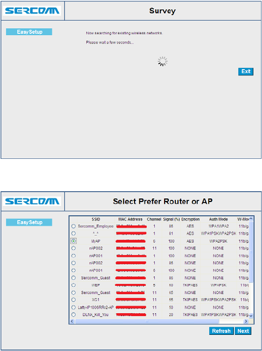
6. Select a Wireless network to extend and click the Next button.
7. In the Password (Network Key) field, type the network pass-
word (also called passphrase or security key) of Root AP
(access point) or Wireless Router.
Page 7
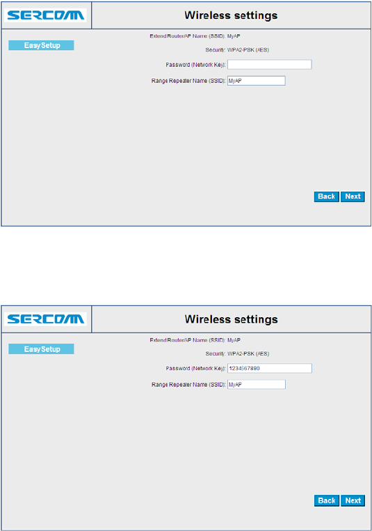
8. In the Range Extender Name (SSID) field, type a name (SSID)
for your RP101v2’s Wireless network and click the Next but-
ton.
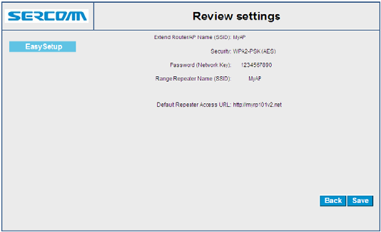
9.
Click the Save button, then the RP101v2 will reboot and the
settings are applied.
Page 8
The RP101v2 (Wireless Repeater) is now ready for use.
10. Use a Wireless network manager on the computer or mobile
device to connect to the RP101v2’s newly created Wireless
network.
Example :
The wireless setting of RP101v2 is as below:
SSID : MyAP
Security : WPA2-PSK (AES)
Password (Network Key) : 1234567890
You also can use an Ethernet cable to connect a computer to the
Ethernet port on the RP101v2.
Page 9
Appendix A
Specifications
Network Camera
Model Wireless Repeater
Dimensions 40.7mm x 57mm x 91.7mm
Operating Temperature 0 C to 40 C
Frequency Band 2.4 G
PHY Rate Up to 300 Mbps
Storage Temperature -20 C to 70 C
Network Protocols TCP/IP, HTTP, DHCP, NTP
Network Interface 1 Ethernet 10/100BaseT LAN connection
Wireless interface IEEE 802.11n/802.11b/802.11g compatible,
WEP 64/128 bit, WPA PSK, WPS
US Domain
LEDs 4
Power Module Built-in
Input : AC 100-240V, 50/60 Hz
Page 10
Regulatory Approvals
FCC Statement
This equipment generates, uses and can radiate radio frequency
energy and, if not installed and used in accordance with the in-
structions, may cause harmful interference to radio
communications. However, there is no guarantee that interference
will not occur in a particular installation. If this equipment does
cause harmful interference to radio or television reception, which
can be determined by turning the equipment off and on, the user
is encouraged to try to correct the interference by one of the fol-
lowing measures:
Reorient or relocate the receiving antenna.
Increase the separation between the equipment and receiver.
Connect the equipment into an outlet on a circuit different
from that to which the receiver is connected.
Consult the dealer or an experienced radio/TV technician for
help.
To assure continued compliance, any changes or modifications
not expressly approved by the party responsible for compliance
could void the user's authority to operate this equipment. (Exam-
ple - use only shielded interface cables when connecting to
computer or peripheral devices).
FCC Radiation Exposure Statement
This equipment complies with FCC RF radiation exposure limits
set forth for an uncontrolled environment. This equipment should
be installed and operated with a minimum distance of 20 centime-
ters between the radiator and your body.
This device complies with Part 15 of the FCC Rules. Operation is
subject to the following two conditions:
Page 11
(1) This device may not cause harmful interference, and
(2) This device must accept any interference received, including
interference that may cause undesired operation.
This transmitter must not be co-located or operating in conjunc-
tion with any other antenna or transmitter.