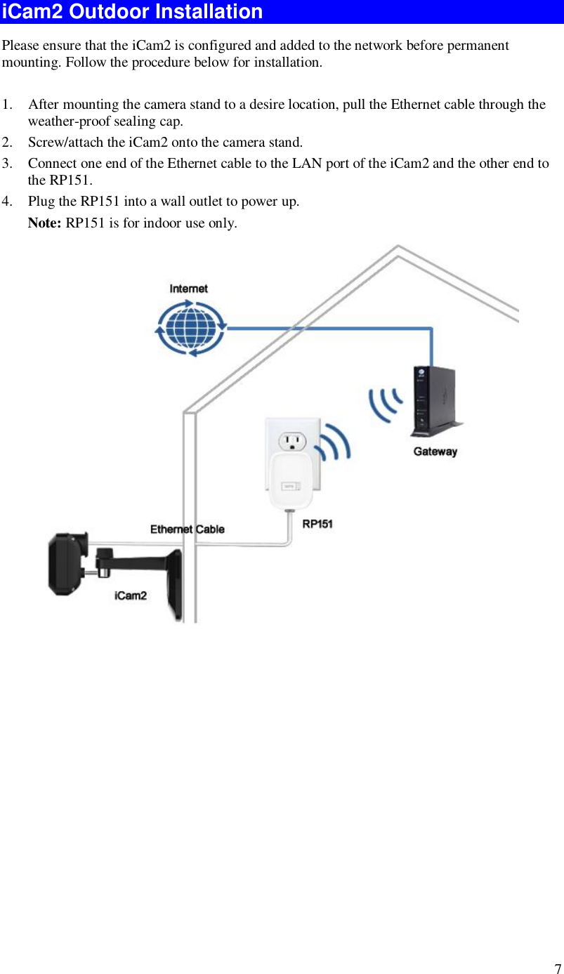
Sercomm RP151 Selectable Dual Band WiFi Adapter User Manual RP151 QIG v1

Sercomm Corporation Selectable Dual Band WiFi Adapter RP151 QIG v1

User manual.pdf

     RP151               User’s Guide
 i Table of Contents CHAPTER 1 INTRODUCTION .......................................................................................... 1  Overview ....................................................................................................................... 1  Physical Details - RP151 ............................................................................................... 2  Package Contents .......................................................................................................... 3  CHAPTER 2 BASIC SETUP ............................................................................................... 4  System Requirements ................................................................................................... 4  Precautions.................................................................................................................... 4  Installation .................................................................................................................... 4  iCam2 Outdoor Installation .......................................................................................... 7  APPENDIX A SPECIFICATIONS ...................................................................................... 8  RP151 ............................................................................................................................ 8  Regulatory Approvals ................................................................................................... 8                     Copyright  2015. All Rights Reserved. Document Version: 1.0  All trademarks and trade names are the properties of their respective owners.
 1 Chapter 1 Introduction This Chapter provides information of the RP151's features, components and capabilities. Overview Congratulations on the purchase of your new RP151. This RP151 is designed to enhance the connectivity between the Wireless Access Point and iCam2 while increasing the coverage of the existing wireless network. With its easy setup operation, this device works seamlessly with most routers and access points.  Features • PoE Support.  You can use PoE (Power over Ethernet) to provide power to the iCam2, so only a single cable connection is required.  Wireless Features  • Supports 802.11n Wireless Standard.  The 802.11n standard provides backward compatibility with the 802.11b and g standards.  The RP151 can work with all 802.11a, 802.11n, 802.11b, 802.11g and 802.11ac Wireless stations. • Supports WPS. WPS (Wi-Fi Protected Setup) can simplify the process of connecting any device to the wireless network by using the press button configuration on the device while connect with iCam2.   1
 2 Physical Details - RP151  Front Panel  Figure 1: Front Panel POWER  l On (Green) - Power On/Normal operation. l Off - Power Off. l Flashing - Pairing with iCam2. Wireless/WPS (Green/Amber) l On (Green) - Wi-Fi connection established. l Off (Green) - Wi-Fi connection is not available.  l Flashing (Green) - Transmitting/Receiving data via Wi-Fi connection. l On (Amber) - WPS connection failed (LED is on for 30 seconds). l Off (Amber) - WPS function is activated.  l Flashing (Amber) - WPS association is in process. WPS Button  Press the WPS button on the device and on your other wireless device to perform WPS function that easily creates an encryption-secured wireless connection automatically. Reset  This button is recessed; you need a pin or paper clip can be used to depress it. To Clear All Data and restore the factory default values: 1. Power On. 2. Use a clip to press the Reset button and keep holding for 10 seconds. 3. Release the Reset Button. The device is now using the factory default values.
 3 Side Panel   Figure 2: Side Panel ETHERNET  Port  Use a standard Ethernet cable (RJ45 connector) to connect iCam2 to the port. Ethernet Activity/Link LED • On - Ethernet connection established, but the connection is idle. • Off - Ethernet connection is not available. • Blink - Data is being transmitted or received via Ethernet connection.   Package Contents The following items should be included in the package: If any of these items are damaged or missing, please contact your dealer immediately. l The RP151 Unit x 1  Note: The RP151 is only functional when connected to the iCam2 via an Ethernet cable.
 4 Chapter 2 Basic Setup This Chapter provides information on how to install and configure the RP151. System Requirements • Use a standard 10/100BaseT network (UTP) cable with RJ45 connector.  Precautions l The RP151 is for indoor use only. l Ensure that RP151 has been set to its factory default settings before installation. l Once the RP151 has been connected to an iCam2, it can not be paired with another iCam2.  Note: The RP151 needs to restore to factory default settings before connecting to another iCam2.  Installation  You must complete the following installation procedure when using the RP151 for the first time.   Figure 3: iCam2 Installation   2
 5 Step 1 - Adding an iCam2 to your network Make sure the Router is powered on and synchronized before adding your iCam2. This step is required when an iCam2 is used for the FIRST time. It only needs to be done ONCE in order to configure the wireless settings for the iCam2. Note: Skip this section if the iCam2 has been set up already.   1. Install the iCam2. (See Figure 3) a. Connect the Ethernet cable to the LAN port of the iCam2. b. Connect the Ethernet cable to the connector of the provided Y-cable.   The wireless and wired modes cannot work simultaneously. It is recommended to first configure the wireless settings of an iCam2 using wired mode. After configuration, disconnect the wire and power, and power on the iCam2 again. Then, it will be ready for wireless operation.  c. Use the Y-cable to connect the router. d. Connect the supplied power adapter to the Y-cable and plug the power adapter into a wall outlet.   Use only the power adapter provided. Using a different one may lead to hardware damage.  e. Check and make sure that the both Power and the Network LEDs are on.  2. Unplug the Y-cable and power off the iCam2. Now the iCam2 is ready to be placed at a desired location, and can operate under wireless mode.
 6 Step 2 - Installation  Figure 4: Installation  1. Move the iCam2 and RP151 to where they are to be placed. 2. Connect the Ethernet cable to the LAN port of the iCam2. 3. Connect the other end of Ethernet cable to the RP151. • Plug the RP151 into a wall outlet to power up.  The iCam2 will pair with the RP151 automatically. No extra configuration needed. 4. Check the LEDs: • The Power LED should be ON • The Wireless/WPS LED should be ON.
 7 iCam2 Outdoor Installation Please ensure that the iCam2 is configured and added to the network before permanent mounting. Follow the procedure below for installation.  1. After mounting the camera stand to a desire location, pull the Ethernet cable through the weather-proof sealing cap.          2. Screw/attach the iCam2 onto the camera stand. 3. Connect one end of the Ethernet cable to the LAN port of the iCam2 and the other end to the RP151. 4. Plug the RP151 into a wall outlet to power up. Note: RP151 is for indoor use only.
 8 Appendix A Specifications RP151 Model  RP151 Dimensions  91.7mm(W) * 56.9mm(D) * 40.7mm(H) (without plug) Operating Temperature  0° C to 40° C Storage Temperature  -20° C to 70° C Network Interface  1 Ethernet 10/100BaseT (RJ45) Buttons  1 Reset Button 1 WPS Button LEDs  2  Antenna  2 x 2 Power Adapter  120V AC Input 12V/1A DC Output (for iCam2)   Regulatory Approvals  FCC Statement This device complies with Part 15 of the FCC Rules. Operation is subject to the following two conditions:  (1) This device may not cause harmful interference, and  (2) This device must accept any interference received, including interference that may cause undesired operation. This transmitter must not be co-located or operating in conjunction with any other antenna or transmitter. Note: The country code selection is for non-US model only and is not available to all US model. Per FCC regulation, all WiFi product marketed in US must fixed to US operation channels only. Operations in the 5.15-5.25GHz band are restricted to indoor usage only. This equipment generates, uses and can radiate radio frequency energy and, if not installed and used in accordance with the instructions, may cause harmful interference to radio communications. However, there is no guarantee that interference will not occur in a particular A
 9 installation. If this equipment does cause harmful interference to radio or television reception, which can be determined by turning the equipment off and on, the user is encouraged to try to correct the interference by one of the following measures: • Reorient or relocate the receiving antenna. • Increase the separation between the equipment and receiver. • Connect the equipment into an outlet on a circuit different from that to which the receiver is connected. • Consult the dealer or an experienced radio/TV technician for help. To assure continued compliance, any changes or modifications not expressly approved by the party responsible for compliance could void the user's authority to operate this equipment. (Example - use only shielded interface cables when connecting to computer or peripheral devices). FCC Radiation Exposure Statement This equipment complies with FCC RF radiation exposure limits set forth for an uncontrolled environment. This equipment should be installed and operated with a minimum distance of 30 centimeters between the radiator and your body. UL Approvals This product is UL and cUL certified and comply with UL60950-1 Information Technology Equipment applicable requirement.
 10 IC Statement Industry Canada statement This device complies with RSS-247 of the Industry Canada Rules. Operation is subject to the following two conditions: (1) This device may not cause harmful interference, and (2) this device must accept any interference received, including interference that may cause undesired operation.  Ce dispositif est conforme à la norme CNR-247 d'Industrie Canada applicable aux appareils radio exempts de licence. Son fonctionnement est sujet aux deux conditions suivantes: (1) le dispositif ne doit pas produire de brouillage préjudiciable, et (2) ce dispositif doit accepter tout brouillage reçu, y compris un brouillage susceptible de provoquer un fonctionnement indésirable.   Caution : (i) the device for operation in the band 5150-5250 MHz is only for indoor use to reduce the potential for harmful interference to co-channel mobile satellite systems; (ii) the maximum antenna gain permitted for devices in the band 5725-5850 MHz shall be such that the equipment still complies with the e.i.r.p. limits specified for point-to-point and non-point-to-point operation as appropriate; and  (iii) Users should also be advised that high-power radars are allocated as primary users (i.e. priority users) of the bands 5650-5850 MHz and that these radars could cause interference and/or damage to LE-LAN devices.  Avertissement: (i) les dispositifs fonctionnant dans la bande 5150-5250 MHz sont réservés uniquement pour une utilisation à l’intérieur afin de réduire les risques de brouillage préjudiciable aux systèmes de satellites mobiles utilisant les mêmes canaux; (ii) le gain maximal d'antenne permis (pour les dispositifs utilisant la bande de 5725 à 5 850 MHz) doit être conforme à la limite de la p.i.r.e. spécifiée pour l'exploitation point à point et l’exploitation non point à point, selon le cas;  (iii) De plus, les utilisateurs devraient aussi être avisés que les utilisateurs de radars de haute puissance sont désignés utilisateurs principaux (c.-à-d., qu’ils ont la priorité) pour les bandes 5650-5850 MHz et que ces radars pourraient causer du brouillage et/ou des dommages aux dispositifs LAN-EL.  Radiation Exposure Statement: This equipment complies with IC radiation exposure limits set forth for an uncontrolled environment. This equipment should be installed and operated with minimum distance 30cm between the radiator & your body. Déclaration d'exposition aux radiations: Cet équipement est conforme aux limites d'exposition aux rayonnements IC établies pour un environnement non contrôlé. Cet équipement doit être installé et utilisé avec un minimum de 20 cm de distance entre la source de rayonnement et votre corps.

Navigation menu