Sercomm RV120W RV120W Wireless N VPN Router User Manual Final Manual
Sercomm Corporation RV120W Wireless N VPN Router Final Manual
UserManual.wiki
>
Sercomm
>
RV120W User Manual
Final Manual
Navigation menu
Upload a User Manual
Namespaces
Wiki Guide
HTML
PDF
Info
Views
User Manual
Discussion / Help
Navigation
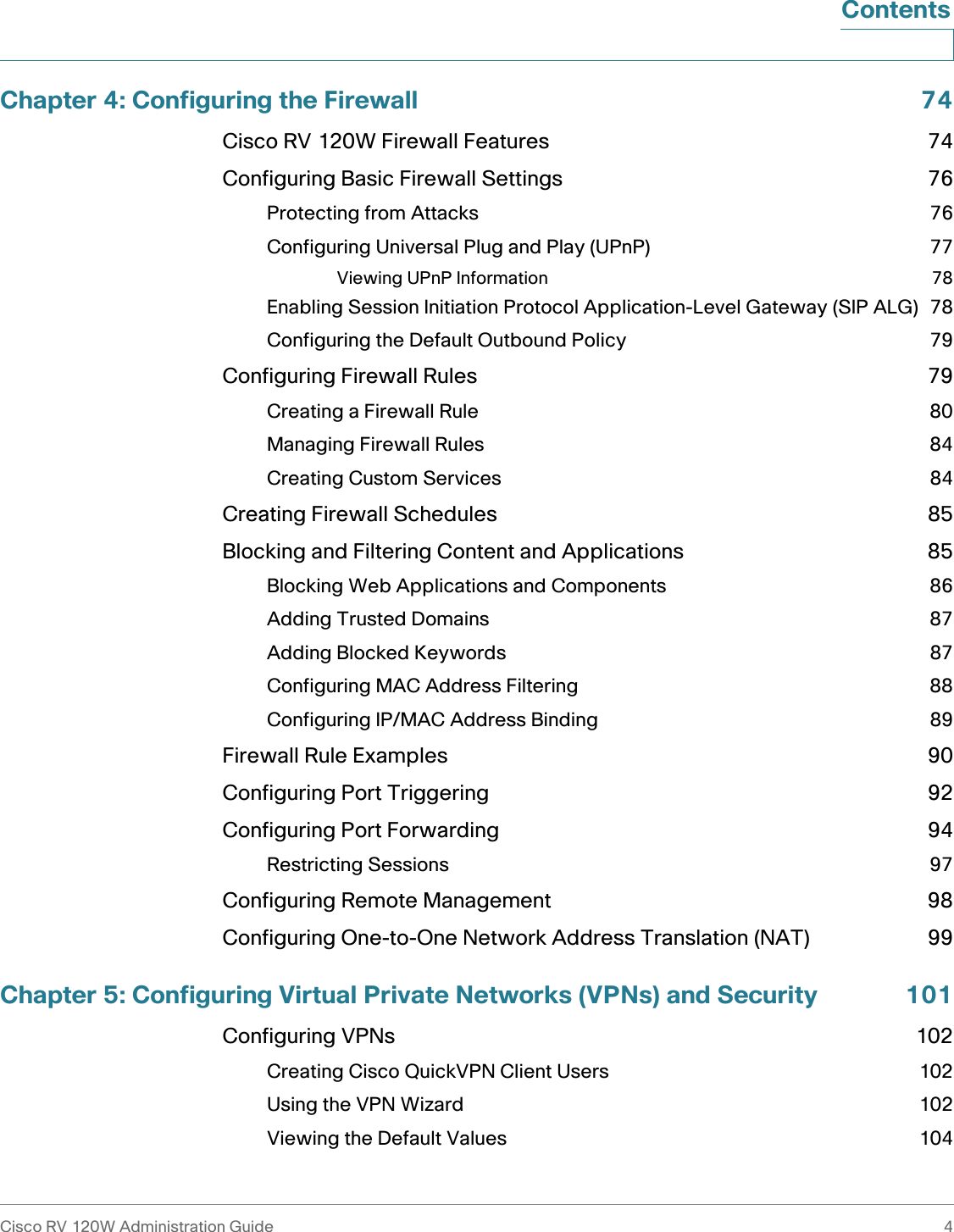
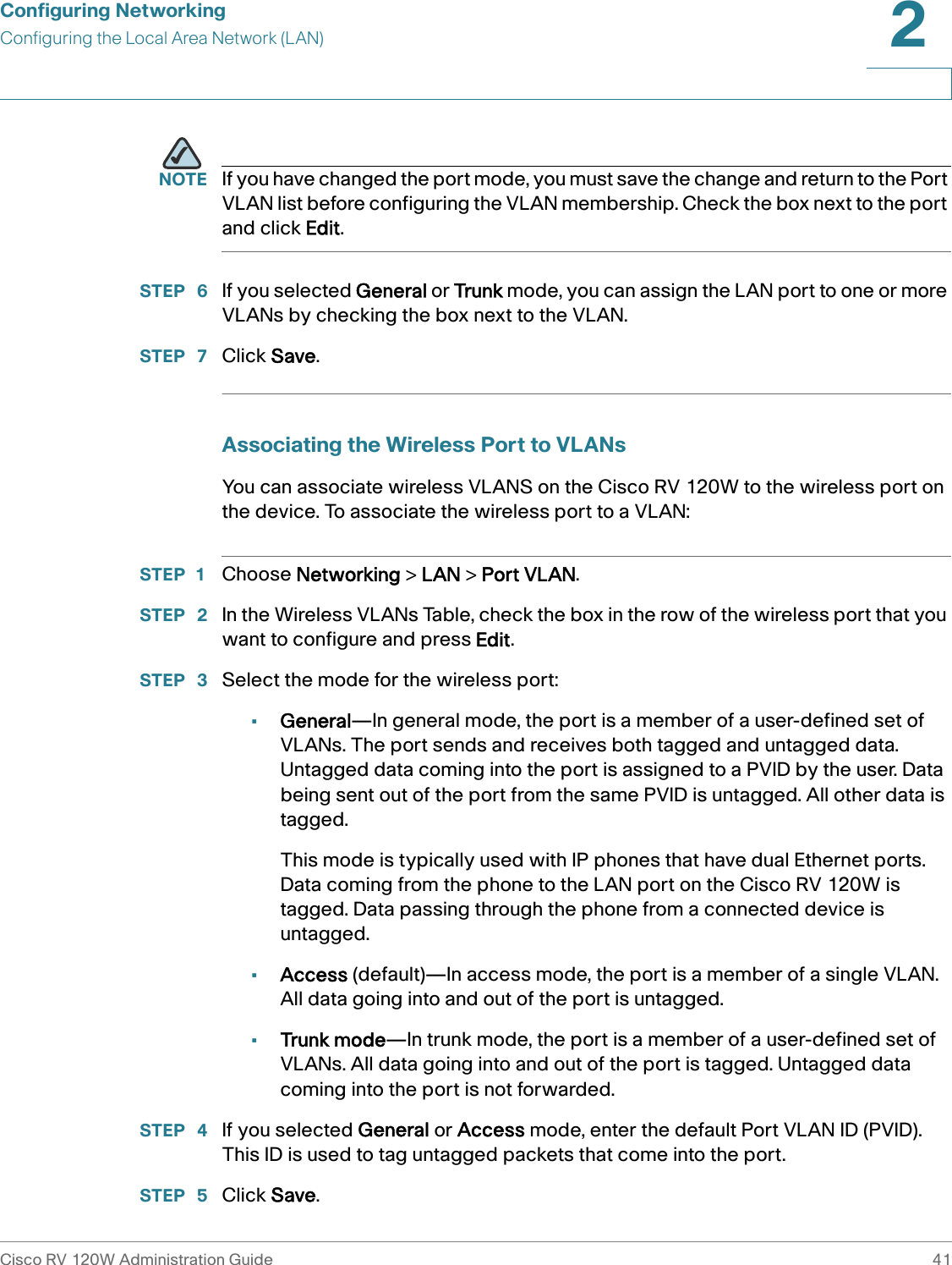
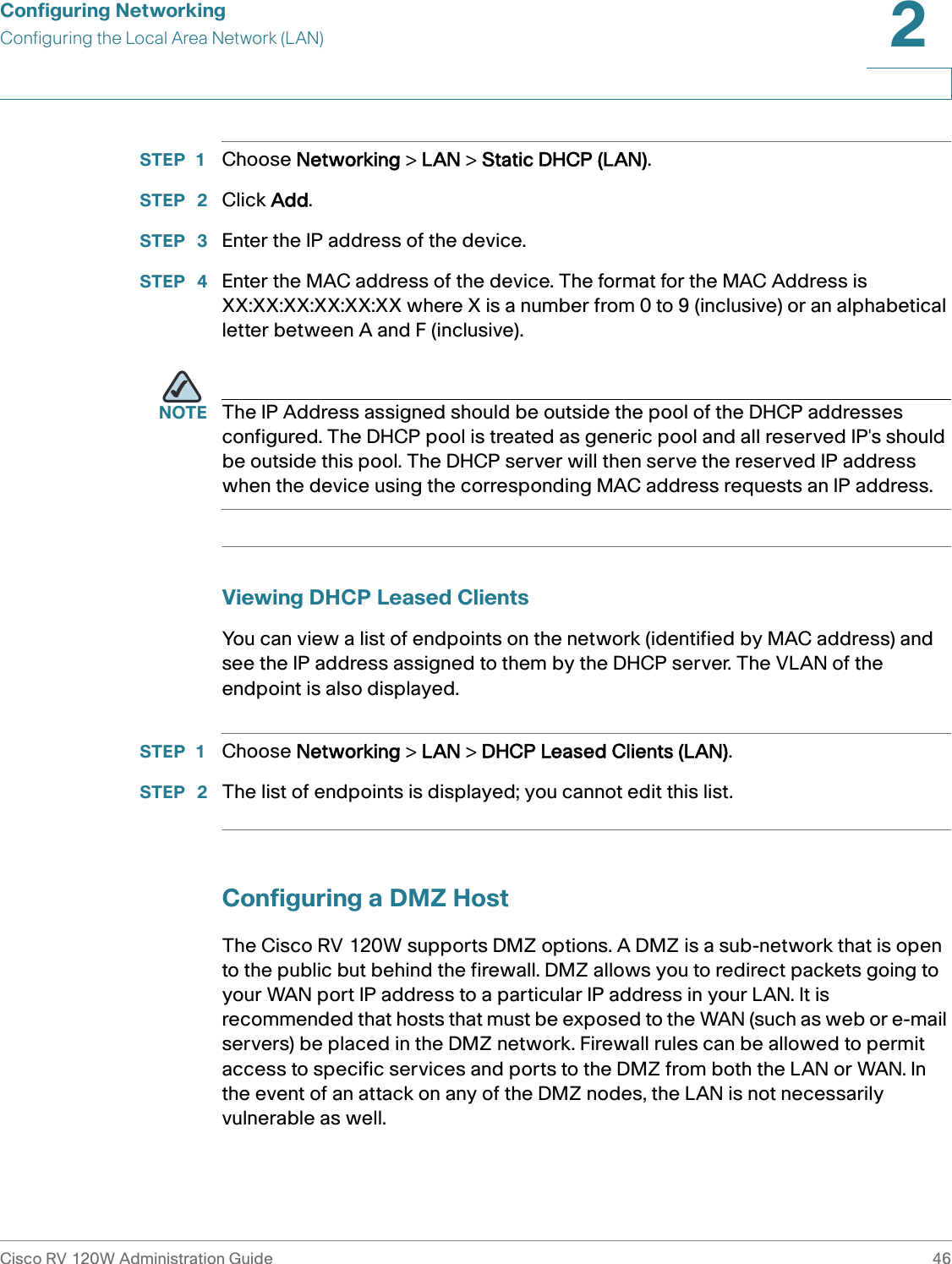
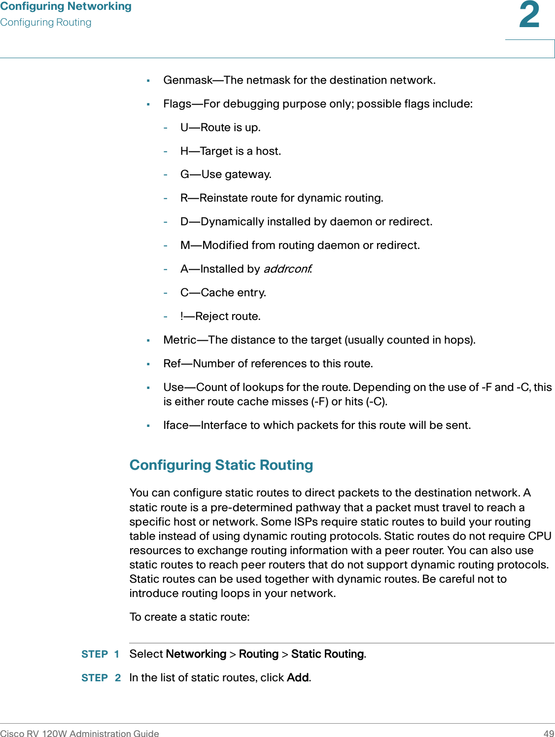
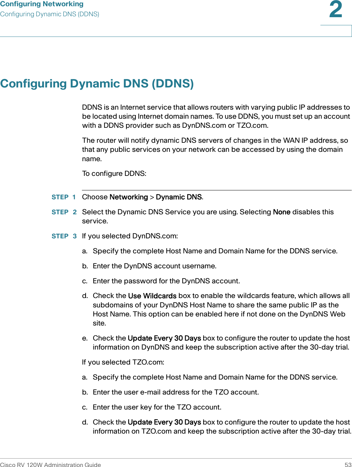
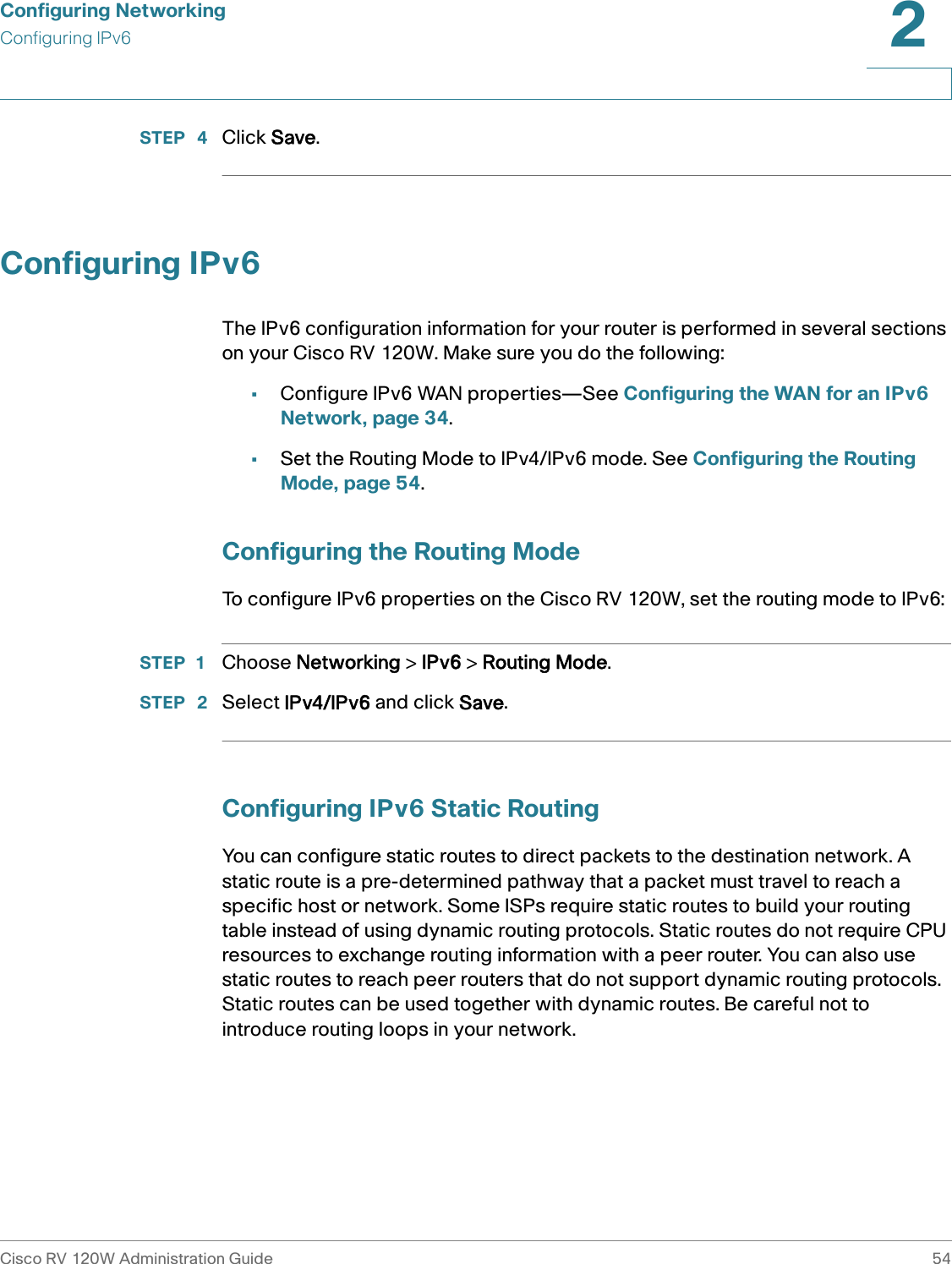
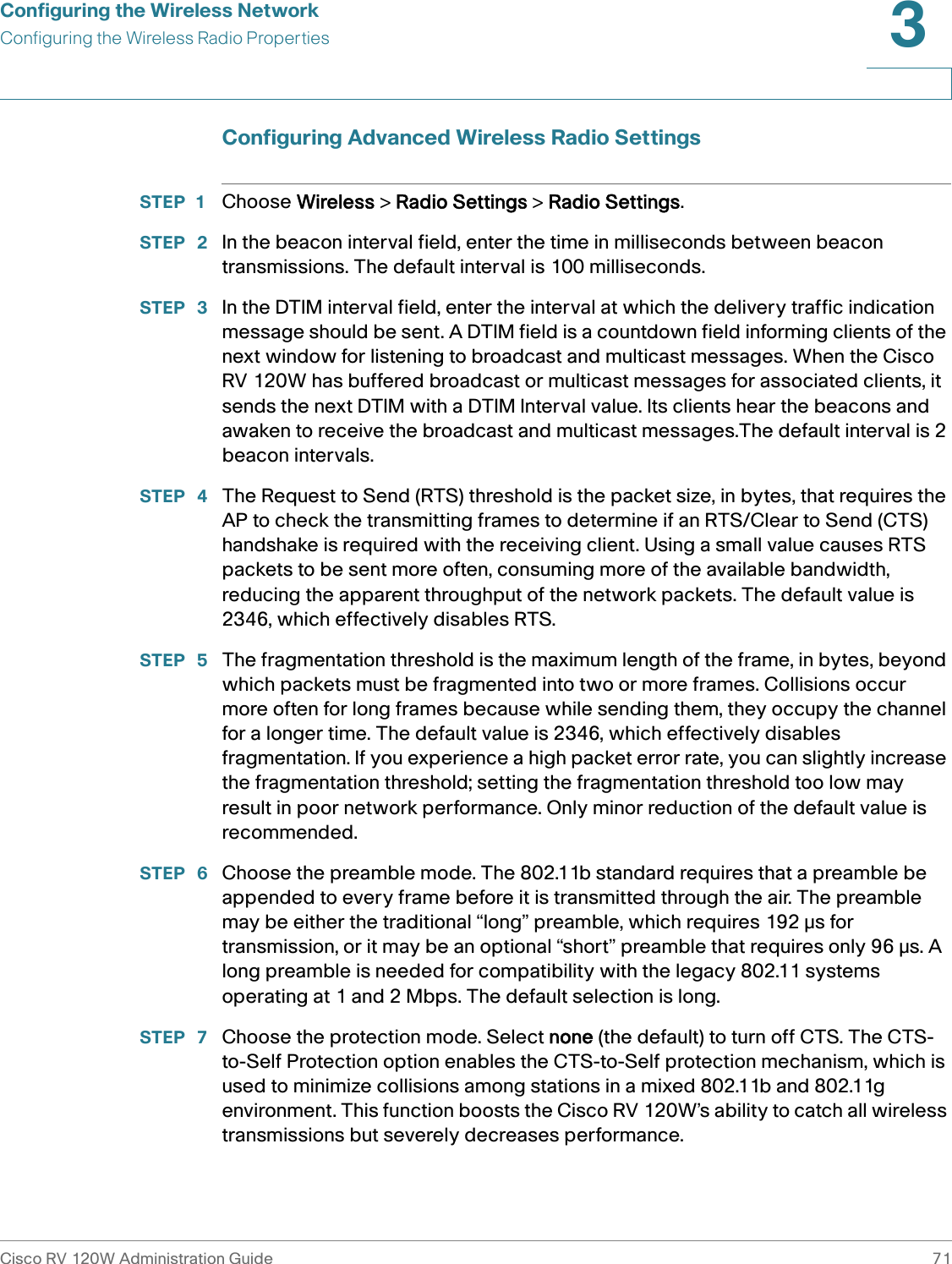
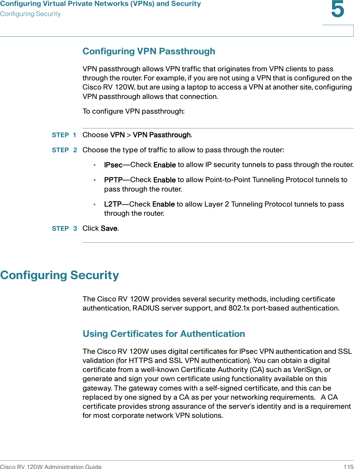
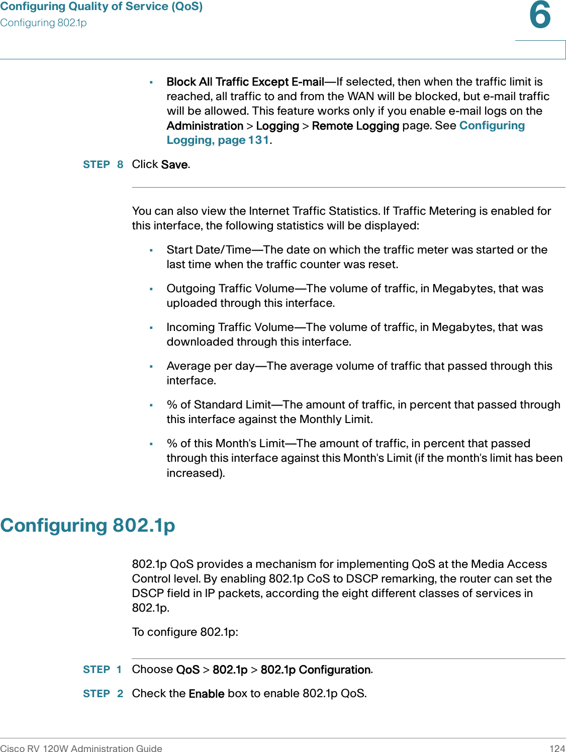
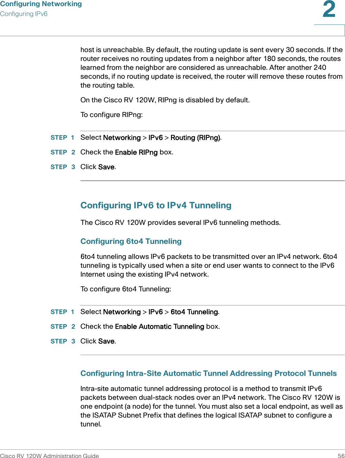
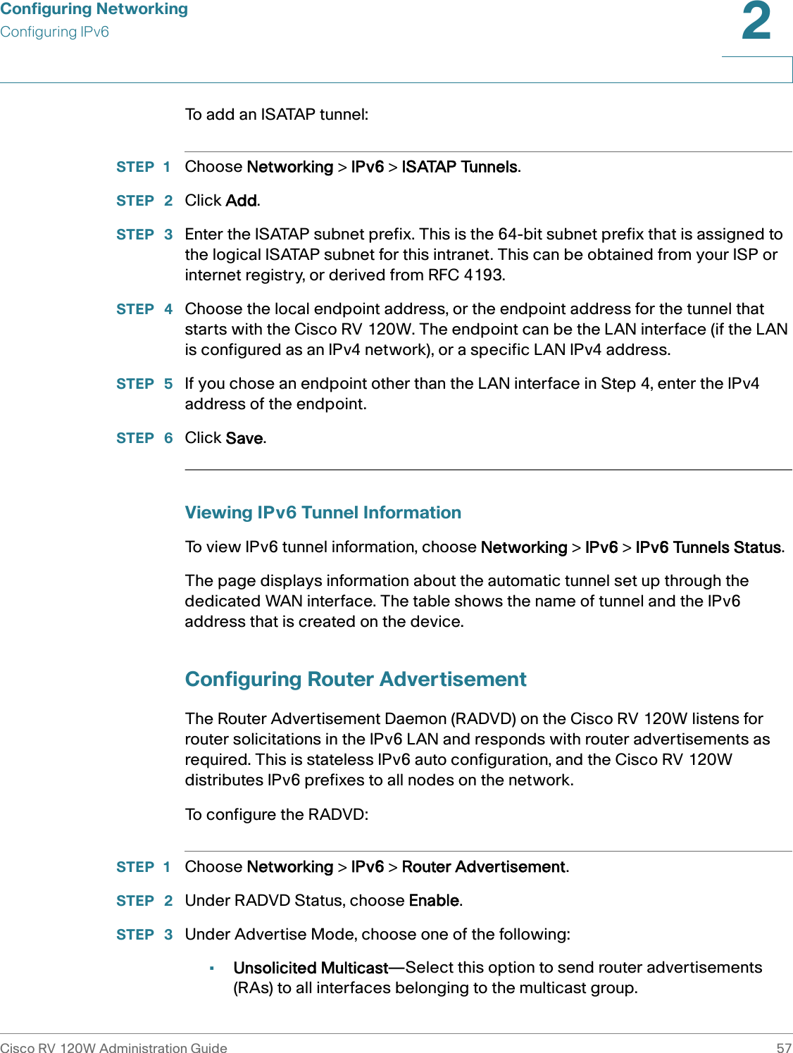
![Configuring NetworkingConfiguring IPv6Cisco RV 120W Administration Guide 552 To create a static route:STEP 1 Select Networking > Routing > Static Routing.STEP 2 In the list of static routes, click Add.STEP 3 Enter the route name.STEP 4 If a route is to be immediately active, check the Active box. When a route is added in an inactive state, it will be listed in the routing table, but will not be used by the router. The route can be enabled later. This feature is useful if the network that the route connects to is not available when you added the route. When the network becomes available, the route can be enabled. STEP 5 In the IPv6 destination field, enter the IPv6 address of the destination host or network for this route.STEP 6 In the IPv6 prefix length field, enter the number of prefix bits in the IPv6 address that define the destination subnet. STEP 7 Choose the physical network interface through which this route is accessible (WAN, LAN, or sit0 tunnel). (The Simple Internet Transition [SIT] is a set of protocol mechanisms implemented in hosts and routers, along with some operational guidelines for addressing and deployment, designed to make the transition from the Internet to IPv6 work with as little disruption as possible. The SIT0 tunnel is a point-to-point tunnel.)STEP 8 Enter the IP Address of the gateway through which the destination host or network can be reached. STEP 9 In the metric field, specify the priority of the route by choosing a value between 2 and 15. If multiple routes to the same destination exist, the route with the lowest metric is used. STEP 10 Click Save.Configuring RIP next generation (RIPng)RIPng (RFC 2080) is a routing protocol based on the distance vector (D-V) algorithm. RIPng uses UDP packets to exchange routing information through port 521. RIPng uses a hop count to measure the distance to a destination. The hop count is referred to as metric, or cost. The hop count from a router to a directly-connected network is 0. The hop count between two directly-connected routers is 1. When the hop count is greater than or equal to 16, the destination network or](https://usermanual.wiki/Sercomm/RV120W/User-Guide-1298185-Page-63.png)
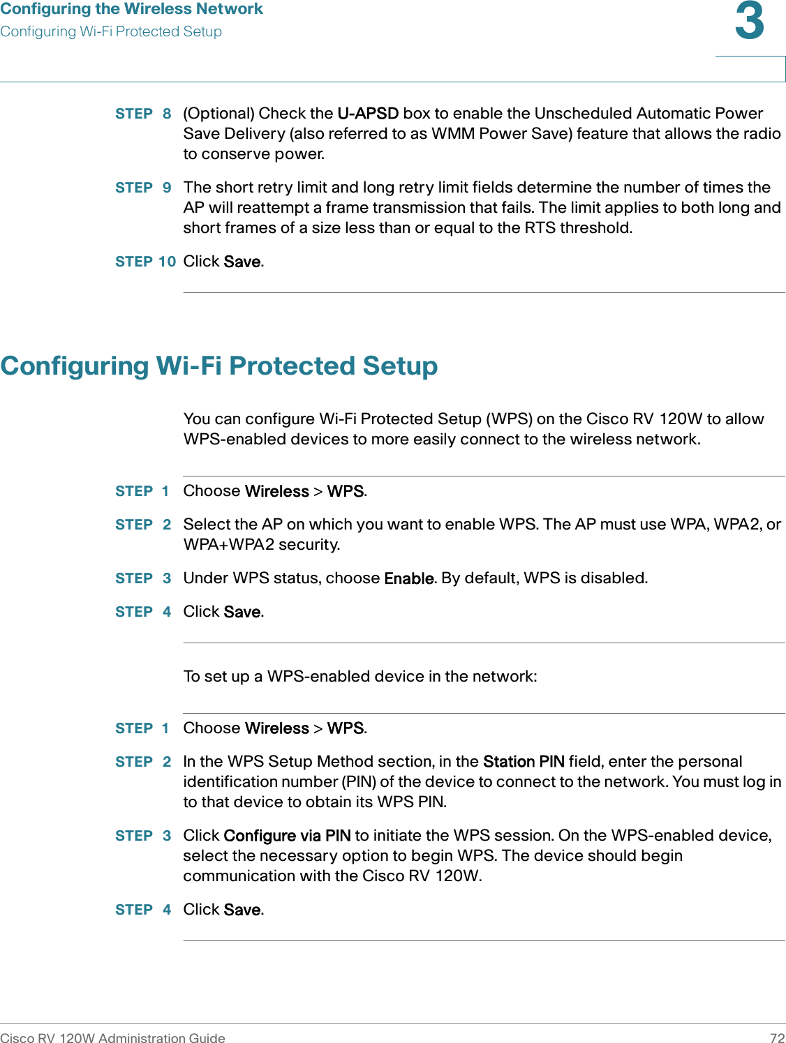
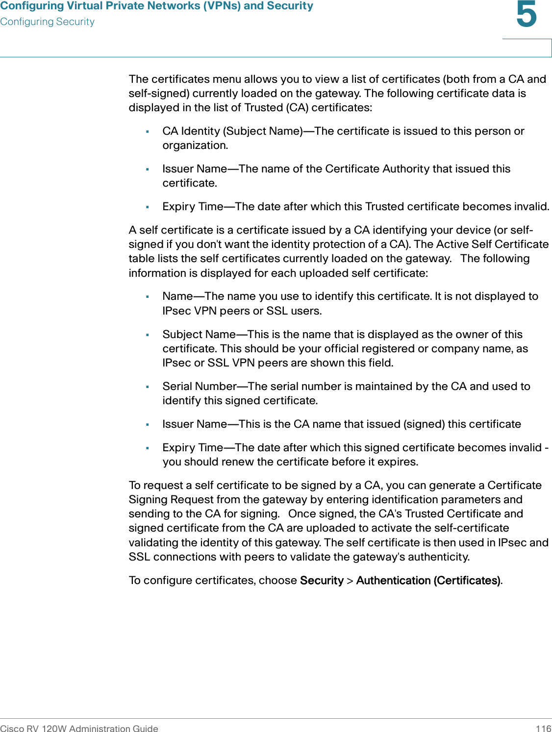
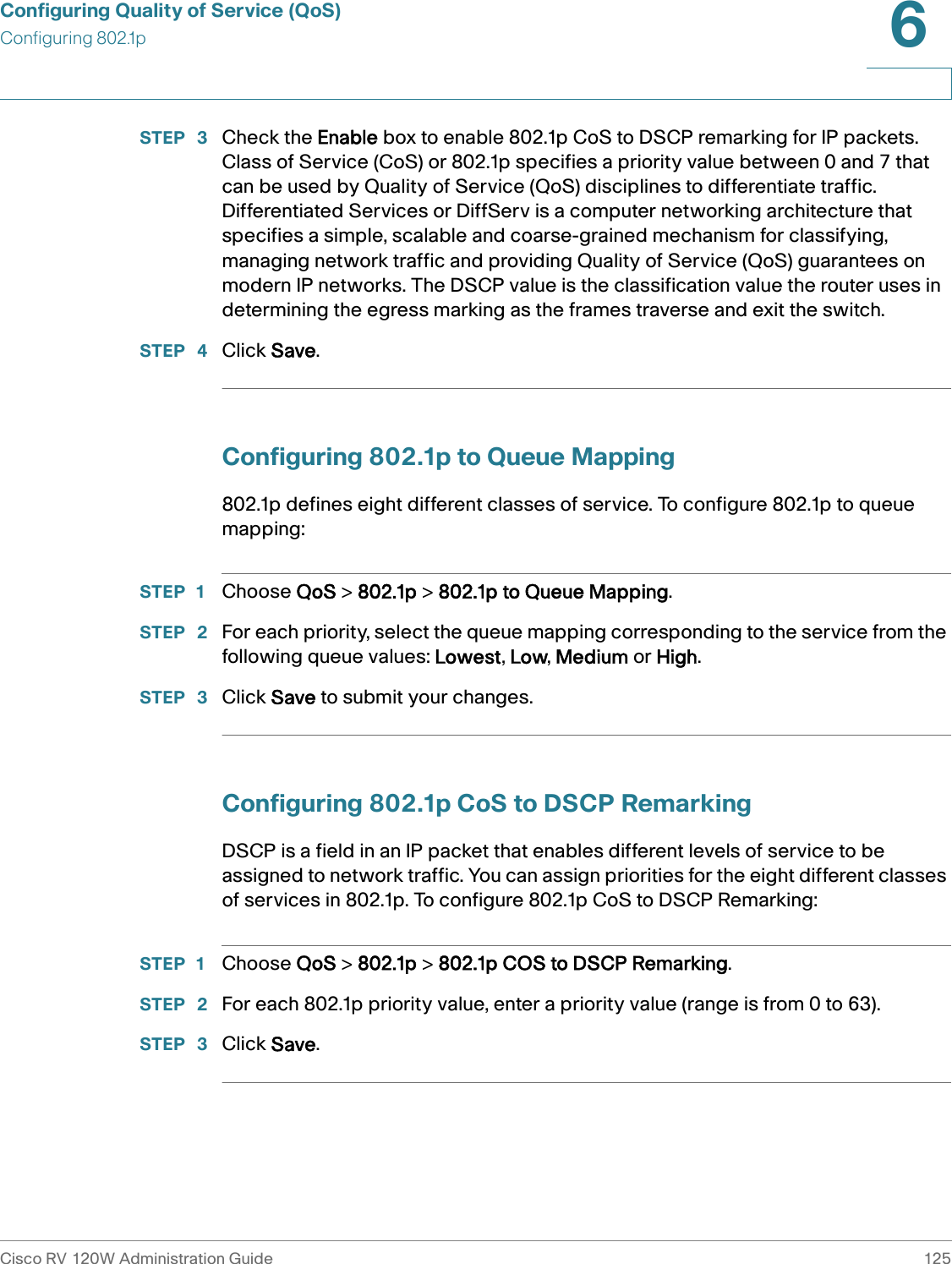
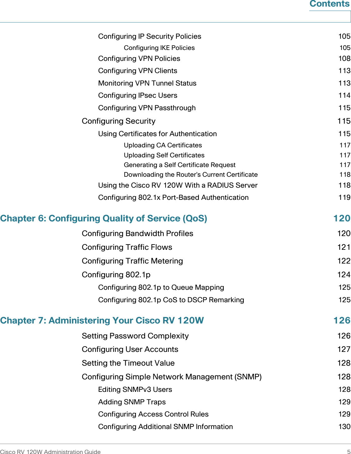
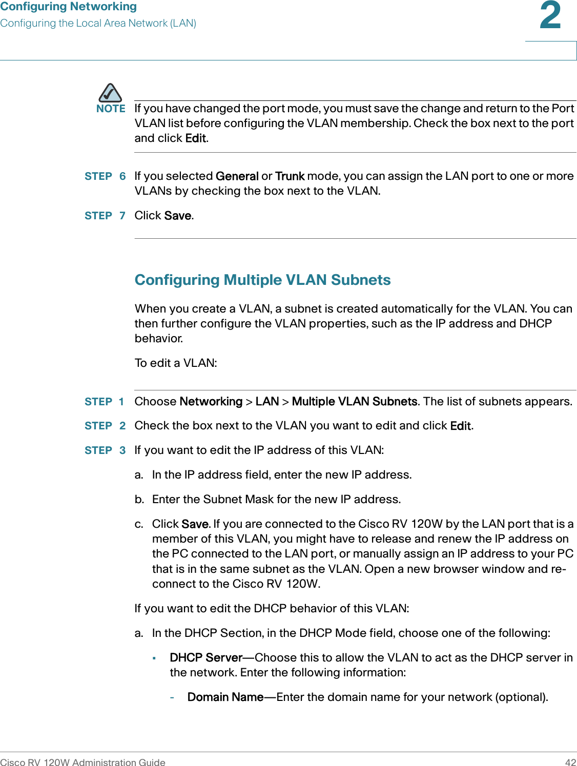
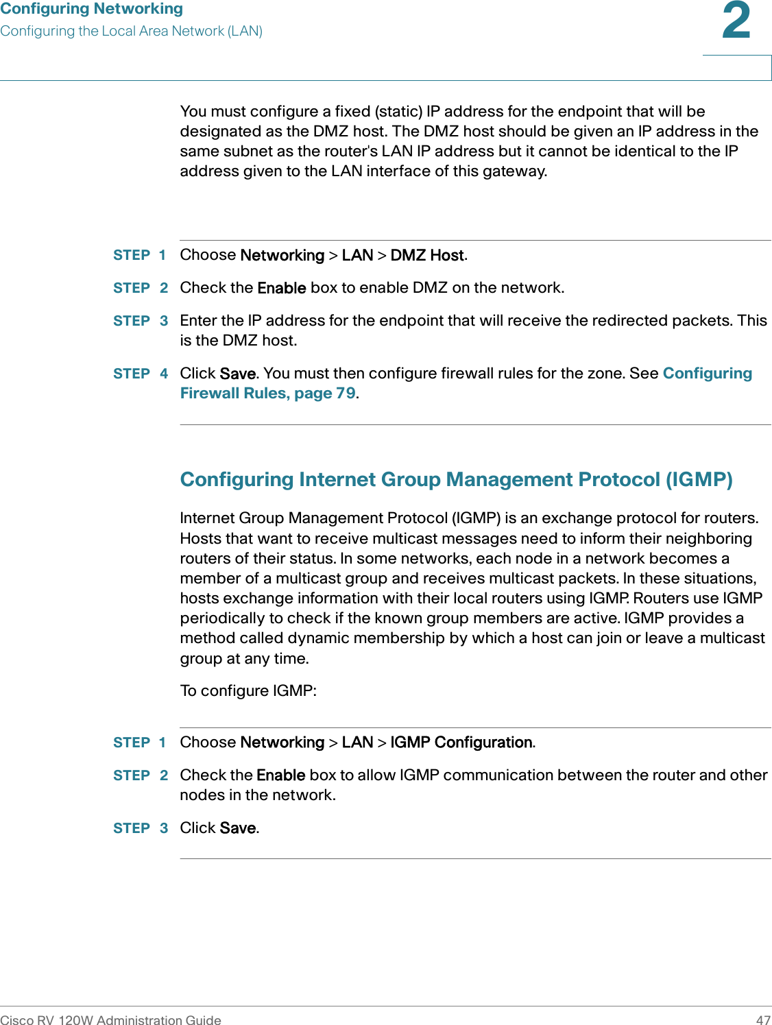
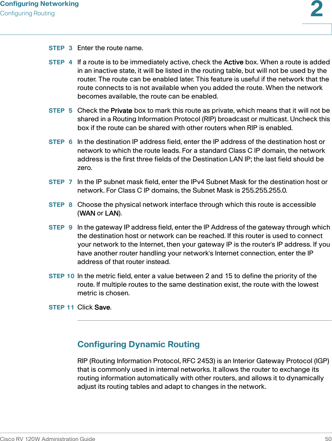
![Configuring NetworkingConfiguring IPv6Cisco RV 120W Administration Guide 582 •Unicast only—Select this option to restrict advertisements to well-known IPv6 addresses only (router advertisements [RAs] are sent to the interface belonging to the known address only).STEP 4 If you chose Unsolicited Multicast in Step 3, enter the advertise interval. The advertise interval is a random value between the Minimum Router Advertisement Interval and Maximum Router Advertisement Interval. (MinRtrAdvInterval = 0.33 * MaxRtrAdvInterval.) The default is 30 seconds.STEP 5 Under RA Flags, check Managed to use the administered/stateful protocol for address auto configuration. Check Other to use the administered/stateful protocol of other, non-address information auto configuration.STEP 6 Under router preference, choose low, medium, or high. The router preference provides a preference metric for default routers. The low, medium and high values are signaled in unused bits in Router Advertisement messages. This extension is backward compatible, both for routers (setting the router preference value) and hosts (interpreting the router preference value). These values are ignored by hosts that do not implement router preference. This feature is useful if there are other RADVD-enabled devices on the LAN. The default is high. STEP 7 Enter the MTU size. The MTU is the size of the largest packet that can be sent over the network. The MTU is used in RAs to ensure all nodes on the network use the same MTU value when the LAN MTU is not well-known. The default is 1500 bytes.STEP 8 Enter the router lifetime value, or the time in seconds that the advertisement messages will exist on the route. The default is 3600 seconds.STEP 9 Click Save.To configure the RADVD available prefixes:STEP 1 Choose Networking > IPv6 > Advertisement Prefixes.STEP 2 Click Add.STEP 3 Choose the IPv6 Prefix Type:•6to4—6to4 is a system that allows IPv6 packets to be transmitted over an IPv4 network. It is used when an end user wants to connect to the IPv6 Internet using their existing IPv4 connection•Global/ISATAP—By using ISATAP, you can integrate IPv6 traffic into a IPv4 network environment. ISATAP uses a locally assigned IPv4 address to create a 64-bit interface identifier for IPv6.](https://usermanual.wiki/Sercomm/RV120W/User-Guide-1298185-Page-66.png)