Sercomm SZDWS02 ZigBee Door / Window Sensor User Manual User guide
Sercomm Corporation ZigBee Door / Window Sensor User guide
Sercomm >
User guide

SZ-DWS02
ZigBee Door / Window Sensor
User Guide

i
Table of Contents
CHAPTER 1 INTRODUCTION...................................................................................... 1
Package Contents ................................................................................................ 1
Specfication ..........................................................................錯誤! 尚未定義書籤。
CHAPTER 2 DEVICE DESCRIPTION .......................................................................... 2
Components.......................................................................................................... 2
Installation Guide ................................................................................................. 3
Preparing the Sensor for Installation ................................................................. 6
Operation............................................................................................................... 7
CHAPTER 3 REGULATORY APPROVAL................................................................... 8
Copyright 201 2. All Rights Reserved.
Document Version: 1.0
All trademarks and trade names are the properties of their respective owners.

1
Chapter 1
Introduction
This Chapter provides an overview of the ZigBee Door/Window Sensor
features and capabilities.
Congratulations on the purchase of your new ZigBee Door/Window Sensor. The
ZigBee Door/Window Sensor is a consumer electronic device, which is used for home
monitoring and security.
Package Contents
The following items should be included:
SZ-DWS02 sensor
Magnet
Adhesive Tape x 2 pcs for Magnet / Sensor
CR123A Lithium Battery x 1 pcs
Screws x 4 pcs for magnet / sensor
Installation & Operation Manual 1 pcs
If any of the above items are damaged or missing, please contact your dealer imme-
diately.
Specification
Frequency: 2.4GHz
Battery type: DC 3V, CR123A Lithium Battery
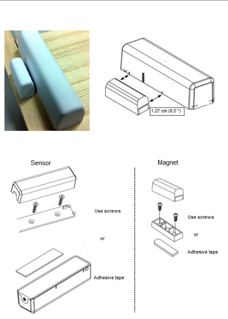
Magnet gap: 1.27 cm ( 0.5” )
Supervisory interval: 60 mins
Low Battery detection: under DC2.7V
Operating temperature: 0° - 50°C (32° - 122°F);
Storage temperature: -20° - 70°C (-4° - 158°F)
Dimensions :
Main Unit : 23 mm x 24 mm x 95 mm (0.91" x 0.94" x 3.74")
Magnet Unit : 31 mm x 13 mm x 18 mm (1.22" x 0.51" x 0.71")
1
2
Chapter 2
Device Description
This Chapter provides device description for the ZigBee Door/Window
Sensor.
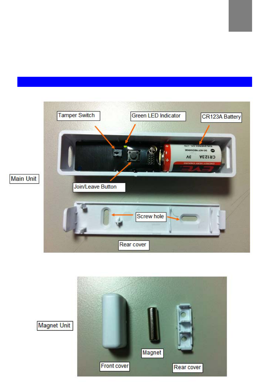
Components
2
3
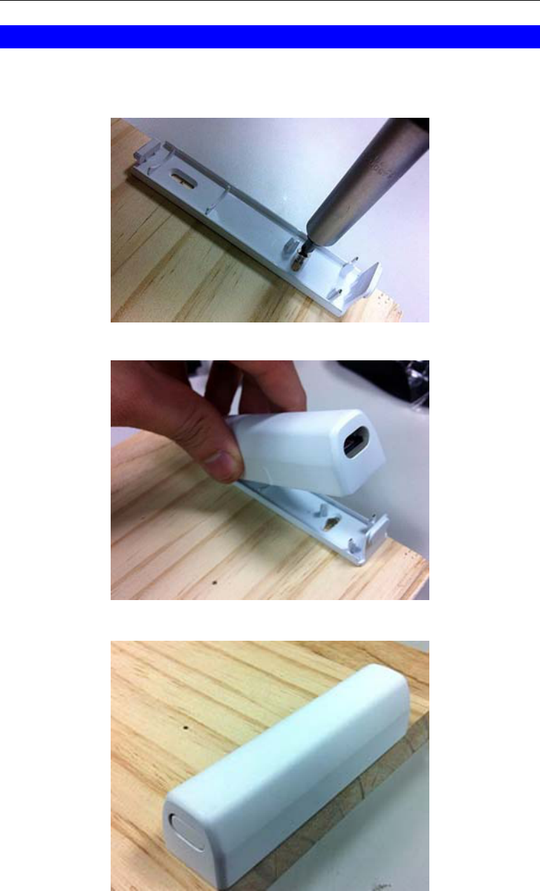
Installation Guide
Main Body:
4
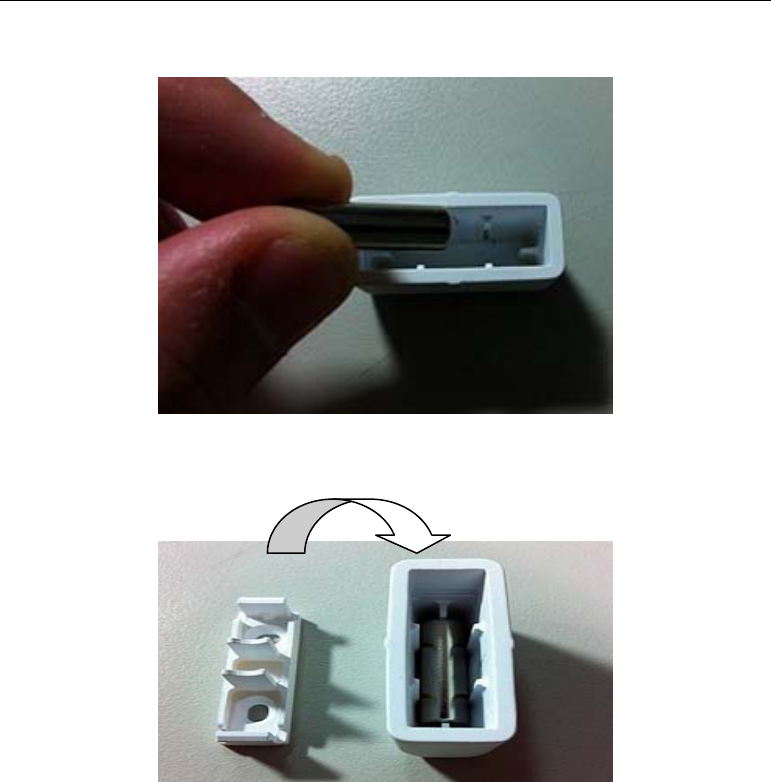
Magnet:
5
The mgnet shall be fixed to close to the specific area, and the distance from sensor
shall not be over 1.27cm (0.5 inch)
6
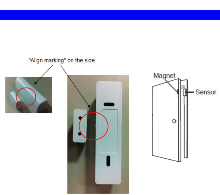
Preparing the Sensor for Installation
The Sensor & Magnet contact can be mounted vertically or horizontally but note that
the Magnet contact must be aligned (on the same side) as the alignment marks on
the Sensor.

7
Operation
1. Normal operation, the LED will not light.
2. The sensor equipped with tamper switch. If the cover of sensor is removed, the
door sensor will send an alarm report to the ZigBee interface controller. Before
replacing the cover, the sensor is under “Awake” mode
:
3. For “Join” a network Put the ZigBee interface controller into “Join” mode, and
following its instruction to add the sensor to controller.
:Join Press < 1 seconds and then start to "Join" processing
While "presee < 1 seconds" , the LED is static on
While running "joint" process, the LED is blinking
:Associate Duration Max >3 seconds for "Join" processing
If joint succesfully, the Green LED will be on 2 seconds and then
off
If joint failed, the Green LED will be off directly.
:Leave Press 10 seconds and then run "Leave" processing

8
Chapter 3
REGULATORY APPROVAL
FCC Statement
This equipment has been tested and found to comply with the limits for a Class B digital
device, pursuant to part 15 of the FCC rules. These limits are designed to provide reasonable
protection against harmful interference in a residential installation. This equipment generates,
uses and can radiate radio frequency energy and, if not installed and used in accordance with
the instructions, may cause harmful interference to radio communications. However, there is
no guarantee that interference will not occur in a particular installation. If this equipment does
cause harmful interference to radio or television reception, which can be determined by turning
the equipment off and on, the user is encouraged to try to correct the interference by one or
more of the following measures:
-Reorient or relocate the receiving antenna.
-Increase the separation between the equipment and receiver.
-Connect the equipment into an outlet on a circuit different from that to which the receiver is
connected.
-Consult the dealer or an experienced radio/TV technician for help.
FCC Radiation Exposure Statement
You are cautioned that changes or modifications not expressly approved by the party responsi-
ble for compliance could void your authority to operate the equipment.
This device complies with Part 15 of the FCC Rules. Operation is subject to the following two
conditions: (1) this device may not cause harmful interference and
(2) this device must accept any interference received, including interference that may cause
undesired operation
3

9
CE Approval
CE Standards
This product complies with the 99/5/EEC directives, including the following safety and
EMC standards:
EN300328-2
EN301489-1/-17
EN60950
CE Marking Warning
This is a Class B product. In a domestic environment this product may cause radio
interference in which case the user may be required to take adequate measures.