Sercomm SZDWS08 Micro Door Window Sensor User Manual SZ DWS08 QIG 20161013
Sercomm Corporation Micro Door Window Sensor SZ DWS08 QIG 20161013
Sercomm >
Users Manual
1
Door/Window Sensor Installation Guide
Door/
Window sensors are designed to secure the perimeter of the residential premise, and provide the ability to
add various automation s
ervices. The Door/Window sensor, which consists of a magnet that attaches to a door or window, will
communicate
door events to the home security system. When the magnet is moved away from the sensor, a signal will be
sent to
the control panel that
communicates the changed state to the security system. Signals can also be used to activate a chime or
convenience lighting based on system settings.
Frequency 2.4GHz
Battery Type CR2450 Battery
Operating Temperature 0
°
C to 50
°
C (32°F - 122°F)
Storage Temperature -20
°
C to 60
°
C (-4°F - 140°F)
Battery Life 4 Years
Dimension Sensor Device: 51 mm x 29 mm x 11 mm (2" x 1.14" x 0.43")
Magnet: 51 mm x 10 mm x 11 mm (2" x 0.39" x 0.43")
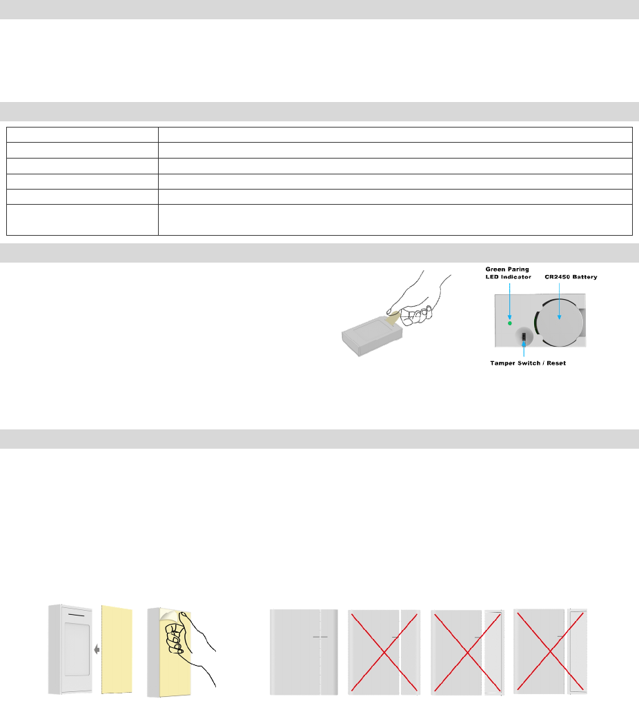
This
Door/Window sensor needs to be paired before installation.
1.
Pull the exposed plastic tab from the sensor. (Figure 1)
2.
The LED indicator will be lit for two seconds to indicate a
Successful booting.
3.
It will blink three times every 5 seconds while scanning the
network.
4.
If network is not found after 100 seconds, the sensor will go
into sleep mode. To wake the sensor again, you need to use
magnet or tamper (Figure 2) to trigger a paring process, and
then sensor will repeat steps from 3 to 4.
1.
Please make sure that the sensor and magnet is located less than 0.25 inch from each other. For optimal performance, it is
highly recommended to install the Door/Window sensor on the fixed frame and the magnet on the moving part of the
door/window. Place the sensor near the top of the door that close to the opening edge of the door. This is the mounting
location for the sensor.
2.
Use the provided double-sided tape on the sensor. Attach the sensor to the door. Press firmly and hold in place for a few
seconds (Figure 3). Secure it with silicone if needed.
3.
Use provided double-sided tape on the magnet. Make sure the alignment of both sensor and magnet are facing each other
(Figure 4). Press firmly and hold in place for a few seconds. Secure it with silicone if needed.
4.
Spacers are used to raise the level of the magnet to be level/closer to sensor. Install Magnets as shown in Figure 5
Introduction
Specification
Installation
Pairing Sensor
Figure 3
Figure 1 Figure 2
Figure 4

2
1.
The Green Pairing LED will stay off during the normal operation.
2.
The sensor is equipped with a tamper switch. If the cover of sensor is removed, the sensor will send an alarm to the home
controller or security system.
I
f sensor needs to be factory defaulted (for example, to prepare it for joining with a home controller or security system).
1.
Remove sensor cover.
2.
Remove the battery from sensor.
3.
Depress the tamper switch for three seconds before inserting the battery.
4.
Insert the battery. The sensor should illuminate the LED once when boot-up/initialization tasks are complete.
5.
Release the tamper switch while the LED is illuminated (it will be lit for 4 seconds). The sensor should then
reset to factory default settings and begin searching for any available home controller or security system. If you need to
reboot the device, remove the battery for at least 5 seconds, then re-insert the battery.
6.
Place the cover back on sensor.
Note: Replace Battery with Panasonic CR2450 or Mitsubishi
CR2450 only. Use of another battery may negatively impact
the performance of the product.
If device has trouble
with pairing to the home controller or security system:
1.
Separate the sensor and magnet or trigger tamper. The sensor will re-attempt to pair.
2.
If device continues to have trouble pairing, remove the battery for 5 seconds and then re-insert it.
3.
If device continues to have trouble pairing, use “Reset to Factory Defaults” procedure to attempt pairing again.
If
device was communicating with the home controller or security system but is no longer communicating:
1.
Move the device to a location closer to the controller. Separate and close the magnet or trigger tamper from the sensor. If
the controller successfully shows the sensor's status, then install a repeater so the system's range can reach the desired
location for the sensor.
2.
If the device has been in use for months or years and the failure is sudden, check the controller to see if the
device has a low battery. Follow the instructions provided to replace the battery.
FCC Statement:
This equipment has been tested and found to comply with the limits for a Class B digital device, pursuant to
Part 15 of the FCC Rules. These limits are designed to provide reason
able protection against harmful interference in a residential
installation. This equipment generates, uses and can radiate radio frequency energy and, if not installed and used in accorda
nce
with the instructions, may cause harmful interference to radio co
mmunications. However, there is no guarantee that interference
will not occur in a particular installation. If this equipment does cause harmful interference to radio or television recepti
on,
which can be determined by turning the equipment off and on, the
user is encouraged to try to correct the interference by one of
the following
measures:
•
Reorient or relocate the receiving antenna.
•
Increase the separation between the equipment and receiver.
•
Connect the equipment into an outlet on a circuit different from that to which the receiver is connected.
•
Consult the dealer or an experienced radio/TV technician for help.
The FCC ID for this device is P27SZDWS0
8
You are cautioned that changes or modifications not expressly approved by the party responsible for comp
liance could void your
authority to operate the equipment.
This device complies with Part 15 of the FCC Rules. Operation is subject to the following two conditions:
(1) This device may not cause harmful interference, and
(2) This device must accept any int
erference received, including interference that may cause undesired operation.
FCC RF Radiation Exposure Statement:
•
This Transmitter must not be co-located or operating in conjunction with any other antenna or transmitter.
•
This equipment complies with FCC RF radiation exposure limits set forth for an uncontrolled environment. This equipment
should be installed and operated with a minimum distance of 20 centimeters between the radiator and your body.
UL
Statement: This device conforms to ANSI/UL STD 634
Reset to Factory Defaults & Reboot
Troubleshooting
Certification
Operation
Canada Statement:
This device complies with Industry Canada’s licence-exempt RSSs. Operation is subject to the following two conditions:(1)
This device may not cause interference; and
(2) This device must accept any interference, including interference that may cause undesired operation of the device.
Le présent appareil est conforme aux CNR d’Industrie Canada applicables aux appareils radio exempts de licence.
L’exploitation est autorisée aux deux conditions suivantes :
(1) l’appareil ne doit pas produire de brouillage;
(2) l’utilisateur de l’appareil doit accepter tout brouillage radioélectrique subi, même si le brouillage est susceptible d’en
compromettre le fonctionnement.
The device meets the exemption from the routine evaluation limits in section 2.5 of RSS 102 and compliance with RSS-102
RF exposure, users can obtain Canadian information on RF exposure and compliance.
Le dispositif rencontre l'exemption des limites courantes d'évaluation dans la section 2.5 de RSS 102 et la conformité à
l'exposition de RSS-102 rf, utilisateurs peut obtenir l'information canadienne sur l'exposition et la conformité de rf.
This transmitter must not be co-located or operating in conjunction with any other antenna or transmitter. This equipment
should be installed and operated with a minimum distance of 20 centimeters between the radiator and your body.
Cet émetteur ne doit pas être Co-placé ou ne fonctionnant en même temps qu'aucune autre antenne ou émetteur. Cet
équipement devrait être installé et actionné avec une distance minimum de 20 centimètres entre le radiateur et votre corps.