Sercomm SZKPD04N Zigbee Keypad User Manual Wireless 802 11g Network Camera
Sercomm Corporation Zigbee Keypad Wireless 802 11g Network Camera
Sercomm >
User Manual
1
SZ-KPD04N Touch Keypad Installation Guide
SZ-KPD04N is a Zigbee touch keypad that controls the security system. It is protected against passcode guessing and supports silent alarm in
case of a forced passcode entry. It is connected via the secure Zigbee protocol.
Frequency
Zigbee 2.4GHz
Battery Type
CR123A x 2
Key Button Type
Capacitive
Operating Temperature
0 C to 50 C (32°F - 122°F) at 90% RH Non-condensing
Storage Temperature
-20 C to 60 C (-4°F - 140°F)
Dimension
65mm x 101mm x 26mm (2.56" x 3.98" x 1.02")
Proximity Sensor Distance
7 cm (Max)
Auto Joining State: A Keypad that does not have a network shall search for a network that is open for joining.
1. Set your security gateway to pairing mode.
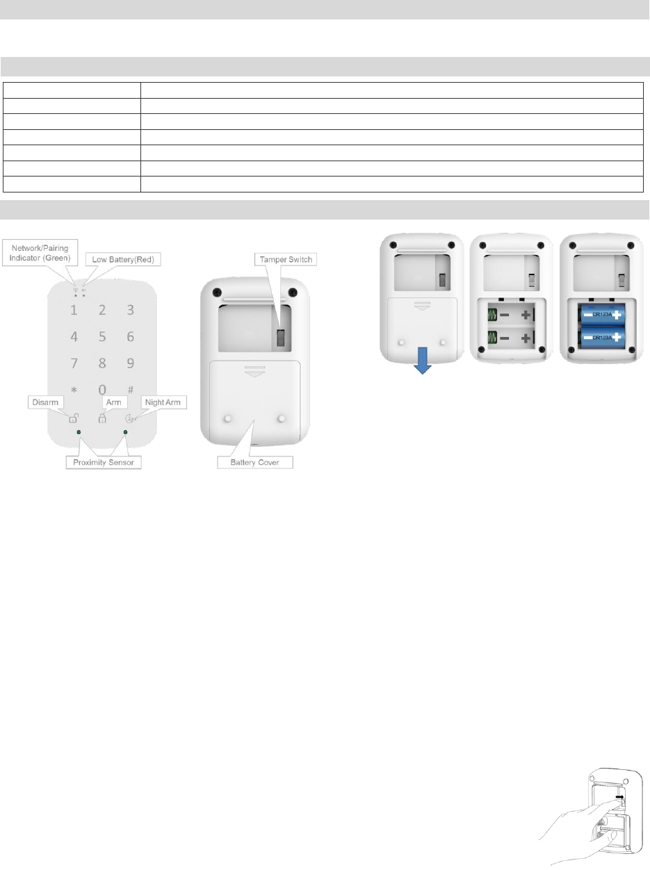
2. Slide out battery cover and insert CR123A battery 2 PCS. (Figure 2)
3. The Network / Pairing indicator (Green LED) will be lit for 2 seconds to indicate the sensor is booting successfully
4. It will Network / Pairing indicator (Green LED) blink three times every 5 seconds while attempting to pair with the security panel or home
controller.
5. If network is not found after 100 seconds, the Keypad will go into sleep mode. To wake the pairing mode again, you need to touch any
Keypad button to trigger a paring process, and then sensor will repeat steps from 3 to 4.
6. Slide in battery cover.
Joined State: A Keypad that has joined shall resume the network.
1. Slide out battery cover and insert CR123A battery 2 PCS. (Figure 2)
2. Illuminate the Network / Pairing indicator (Green LED) for 2 seconds to indicate a successful boot.
3. Resume operation with the existing network.
Manual Defaulting: Default a Keypad puts it into a state where it is ready to be joined to a coordinator.
The process for manually default a Keypad shall be as follows:
1. Remove 2 CR123A battery, press the Tamper switch and hold it. (Figure 3)
2. Insert CR123A batter. Power it up again. The Kepyad should illuminate the Network / Pairing indicator
(Green LED) once all boot up/initialization tasks are complete.
3. Release the tamper switch (in 4 seconds) while the Network / Pairing indicator (Green LED) has been illuminated.
Introduction
Specification
Pairing Keypad
Figure 1
Figure 2
Figure 3
2
4. The Keypad shall then wipe any knowledge of the previous network and other configuration parameters and begin searching for a new
network(Auto Joining State).
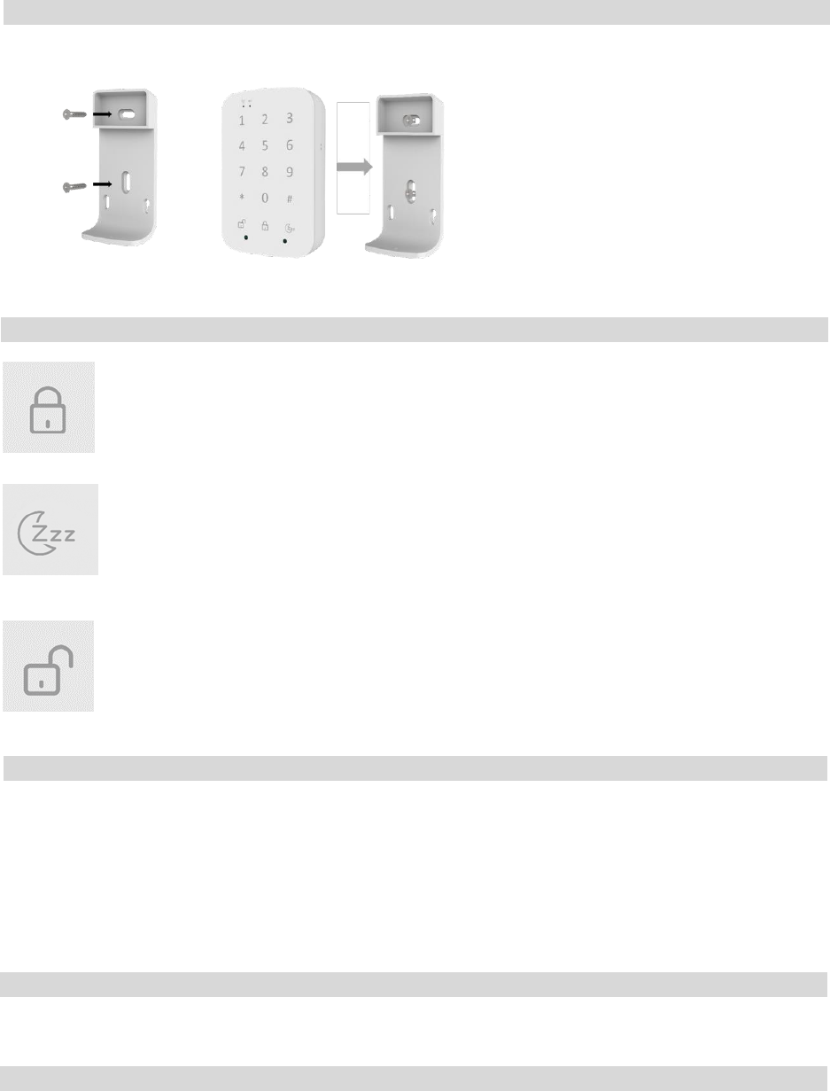
Mount the keypad bracket to the wall in the desired location using the included mounting screws and anchors (Figure 4). Align the keypad to
wall mount bracket and snap keypad onto bracket. (Figure 5)
Arm Away Button
Press this button and enter your 4 digit security code to arm in away mode.
For Example: Press 1,2,3,4 digit and press “Arm away” button.
Once the Arm has successfully. The beeper will “beep” on 1 second then off.
Arm Night Button
Press this button and enter your 4 digit security code to arm in night mode.
For Example: Press 1,2,3,4 digit and press “Arm Night” button.
Once the Arm has successfully. The beeper will “beep” on 1 second then off.
Disarm Button
Press this button and enter your 4 digit security code to disarm mode.
For Example: Press 1,2,3,4 digit and press “Disarm” button.
Once the Arm has successfully. The beeper will “beep” on 1 second then off.
1. The Network/pairing LED and low battery LED will stay off during the normal operation.
2. The sensor is equipped with a tamper switch. If the cover of sensor is removed, the sensor will send an alarm to the home controller or
security system.
3. Proximity Detection: The keypad is able to detect the user’s presence within 7 cm (Max). Once detected the keypad will awake and
backlit illuminate.
4. Lithium batteries do not charge
5. If enter wrong digit security code, the beeper will “beep” “beep” 2 times.
6. Keypad backlit keep on 5 second once proximity sensor detect user.
To ensure that your system continues to functioning as intended, you must test your system weekly. Please contact your security monitoring
company for instructions on how to test your system
Normal Function
Weekly Testing
Certification
Operation
Keypad Bracket Instruction
Figure 4
Figure 5
3
CAUTION:
RISK OF EXPLOSION IF BATTERY IS REPLACED BY AN INCORRECTED TYPE. DISPOSE OF USED
BATTERIES ACCORDING TO THE INSTRUCTIONS.
FCC Statement: This equipment has been tested and found to comply with the limits for a Class B digital device, pursuant to Part 15 of the
FCC Rules. These limits are designed to provide reasonable protection against harmful interference in a residential installation. This equipment
generates, uses and can radiate radio frequency energy and, if not installed and used in accordance with the instructions, may cause harmful
interference to radio communications. However, there is no guarantee that interference will not occur in a particular installation. If this
equipment does cause harmful interference to radio or television reception, which can be determined by turning the equipment off and on, the
user is encouraged to try to correct the interference by one of the following measures:
• Reorient or relocate the receiving antenna.
• Increase the separation between the equipment and receiver.
• Connect the equipment into an outlet on a circuit different from that to which the receiver is connected.
• Consult the dealer or an experienced radio/TV technician for help.
You are cautioned that changes or modifications not expressly approved by the party responsible for compliance could void your authority to
operate the equipment.
This device complies with Part 15 of the FCC Rules. Operation is subject to the following two conditions:
(1) This device may not cause harmful interference, and
(2) This device must accept any interference received, including interference that may cause undesired operation.
FCC RF Radiation Exposure Statement:
• This Transmitter must not be co-located or operating in conjunction with any other antenna or transmitter.
• This equipment complies with FCC RF radiation exposure limits set forth for an uncontrolled environment. This equipment should be
installed and operated with a minimum distance of 20 centimeters between the radiator and your body.
Canada Statement: This device complies with Industry Canada’s licence-exempt RSSs. Operation is subject to the following two conditions:(1)
This device may not cause interference; and (2) This device must accept any interference, including interference that may cause undesired
operation of the device.
Le présent appareil est conforme aux CNR d’Industrie Canada applicables aux appareils radio exempts de licence. L’exploitation est autorisée
aux deux conditions suivantes : (1) l’appareil ne doit pas produire de brouillage; (2) l’utilisateur de l’appareil doit accepter tout brouillage
radioélectrique subi, même si le brouillage est susceptible d’en compromettre le fonctionnement.
The device meets the exemption from the routine evaluation limits in section 2.5 of RSS 102 and compliance with RSS-102 RF exposure, users
can obtain Canadian information on RF exposure and compliance.
Le dispositif rencontre l'exemption des limites courantes d'évaluation dans la section 2.5 de RSS 102 et la conformité à l'exposition de RSS-102
rf, utilisateurs peut obtenir l'information canadienne sur l'exposition et la conformité de rf.
This transmitter must not be co-located or operating in conjunction with any other antenna or transmitter. This equipment should be installed
and operated with a minimum distance of 20 centimeters between the radiator and your body.
Cet émetteur ne doit pas être Co-placé ou ne fonctionnant en même temps qu'aucune autre antenne ou émetteur. Cet équipement devrait être
installé et actionné avec une distance minimum de 20 centimètres entre le radiateur et votre corps.