Sercomm SZWTD02N Zigbee Water Sensor User Manual SZ WTS02N QIG 20150729
Sercomm Corporation Zigbee Water Sensor SZ WTS02N QIG 20150729
Sercomm >
User manual
ZigBee
Water
Sensor Installation Guide
This is a battery-powered indoor ZigBee Water Sensor, which monitors and reports the indoor water
leak status to the coordinator of a ZigBee home security network. The Water Sensor is designed to alert you when
there is water present and potential flooding. It is ideally suited for a wide range of locations including bathrooms,
laundry rooms, kitchens, basements, washing machines, air conditioner condensation drip pans
Frequency 2.4GHz
Batter Type AA Battery x 2 (pre-installed)
Water Sensor 6 ft Water Sensor Cable
Operating Temperature 0° C to 40° C (32°F - 104°F)
Storage Temperature -20° C to 60° C (-4°F - 140°F)
Battery Life 2 years
RF Range (Air) 100M
Dimension 74 x 74 x 2.5 mm
Accessary Part 2 screws
Adhesive
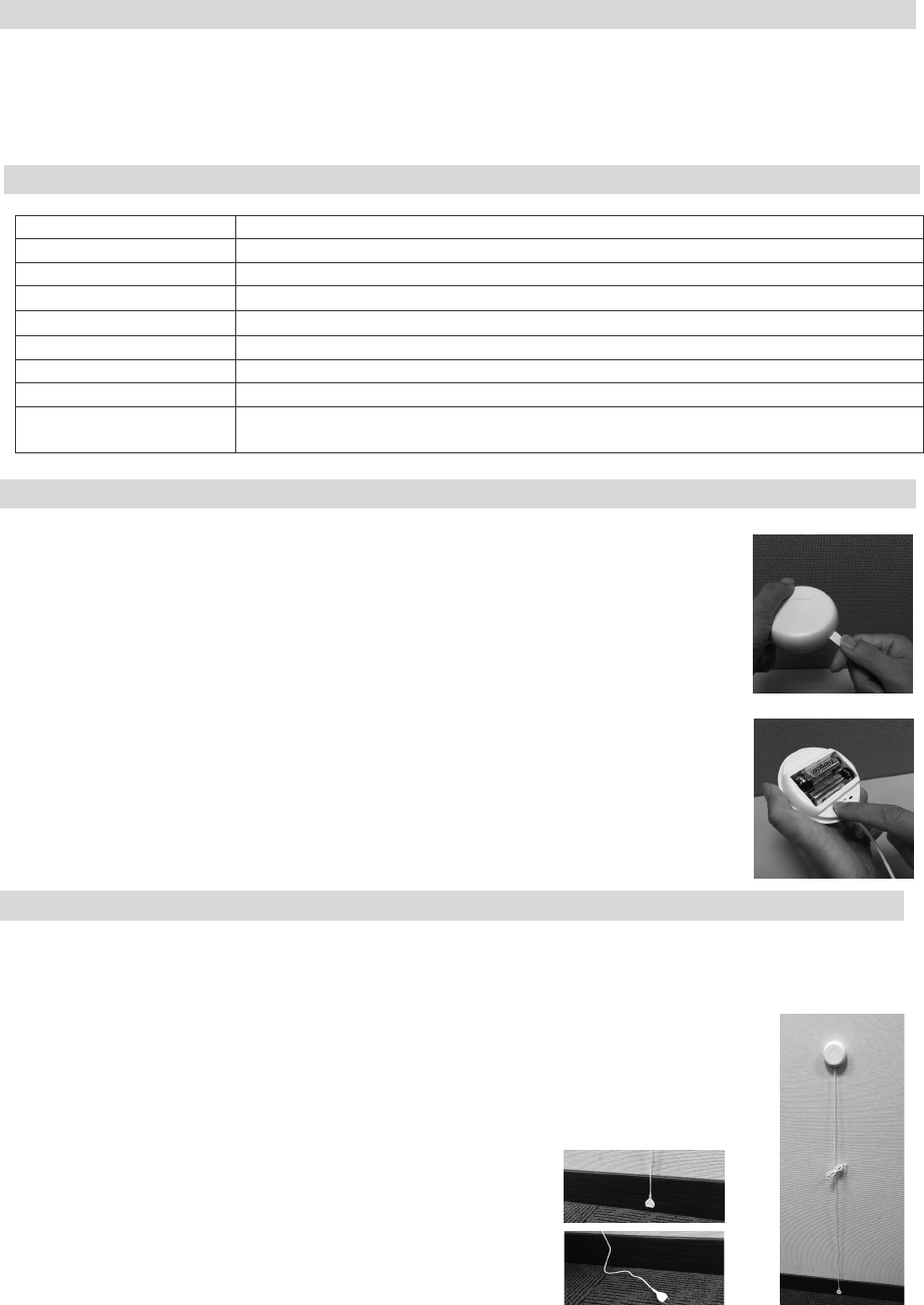
This water sensor needs to be paired before installation.
1. Pull the exposed plastic tab from the sensor (Figure 1.)
2. If network is not found after 100 seconds, the sensor will enter sleep mode.
You need to use water sensor to trigger a paring process, and then sensor will repeat
1~2 procedure.
3. If the pairing mode ends before Zigbee coordinator is connected, or the tab is
accidentally removed: Insert a slotted screwdriver (or a dime-sized coin) into the
indent on the side and open the bottom half of the unit. Press the pairing button
once to re-start pairing mode. The LED light will be solid for 2 seconds, then flash
(Figure 2.).
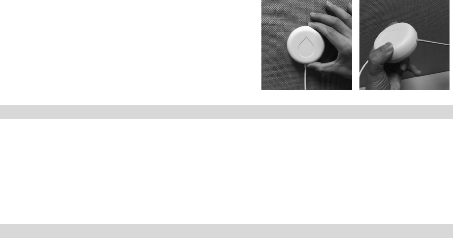
1. The two sensor probes at the end of the cable are close to the base of the area to be monitored
(about 1-2mm away), or the probe housing is laying flat on the base of the area to be monitored.
The probes should NOT be touching the surface to be monitored. (Figure 3.)
2. In order for the sensor to work, BOTH probes must have contact with water. Make
sure both probe tips are positioned correctly. Use the included adhesive pad to
secure the probe housing to a clean, dry surface. Possible Water Sesnor areas include:
in the water heater tray, in the sump pump, at the toilet base, or at ground-level of the
basement. (Figure 4.)
Figure 1
Introduction
Specification
Installation
Pairing & Sensor Testing
Figure
3
Figure
4
Figure
2
3. Once Water probes are in position, use the included adhesive pad to secure the main unit to a clean, dry
surface. Adhesive pad may damage certain surfaces during removal, so please test before using. (Figure 5.)
4. To attach Water Sensor more permanently, use the included screws for mounting. Insert a slotted screwdriver
(or a dime-sized coin) into the indent on the side of Water sensor to open the unit. Screw the back of the unit
into the surface, making sure to position it so it has the correct orientation when reassembled. Snap the unit
back together. (Figure 6.)
If the sensor needs to be put in a factory defaulted state (for example, to prepare it for joining with a home
controller or security system). The process shall be as follows:
•Remove the battery cover from water sensor.
•Depress the pairing button before inserting the battery. (Figure 2.)
•Insert the battery. The water sensor should illuminate the LED once all bootup/initialization tasks are complete.
•Release the tamper switch while the LED is illuminated (it will be lit for 4 seconds). The water sensor should
then reset to factory default settings and begin searching for a home controller or security system.
If you need to reboot the device, remove the battery for at least 15 seconds, then reinsert the battery.
FCC Statement: This equipment has been tested and found to comply with the limits for a Class B digital device,
pursuant to Part 15 of the FCC Rules. These limits are designed to provide reasonable protection against harmful
interference in a residential installation. This equipment generates, uses and can radiate radio frequency energy and,
if not installed and used in accordance with the instructions, may cause harmful interference to radio
communications. However, there is no guarantee that interference will not occur in a particular installation. If this
equipment does cause harmful interference to radio or television reception
, which can be determined by turning the
equipment off and on, the user is encouraged to try to correct the interference by one of the following measures:
•Reorient or relocate the receiving antenna.
•Increase the separation between the equipment and receiver.
•Connect the equipment into an outlet on a circuit different from that to which the receiver is connected.
•Consult the dealer or an experienced radio/TV technician for help.
To assure continued compliance, any changes or modifications not expressly appro
ved by the party responsible for
compliance could void the user's authority to operate this equipment. (Example -
use only shielded interface cables
when connecting to computer or peripheral devices).
This transmitter must not be co-located or operating in conjunction with any other antenna or transmitter.
FCC Radiation Exposure Statement: This equipment complies with FCC RF radiation exposure limits set forth
for an uncontrolled environment.
This device complies with Part 15 of the FCC Rules. Operation is subject to the following two conditions:
(1) This device may not cause harmful interference, and
(2) This device must accept any interference received, including interference that may cause undesired operation.
Reset to Factory Defaults & Reboots
Certification
Figure
5
Figure
6