Manual

Wireless-N
USB Adapter
UB812EN Manual

i
Table of Contents
CHAPTER 1 INTRODUCTION .............................................................................................1
Package Contents ..............................................................................................................1
Features..............................................................................................................................1
LED.....................................................................................................................................1
Operation ...........................................................................................................................2
CHAPTER 2 INITIAL INSTALLATION..............................................................................3
Requirements.....................................................................................................................3
Procedure...........................................................................................................................3
CHAPTER 3 USING THE WINDOWS UTILITY................................................................7
Overview ............................................................................................................................7
System Tray Icon...............................................................................................................7
General Screen...................................................................................................................8
Adapter Settings................................................................................................................9
Profile Screen...................................................................................................................10
Available Network Screen ..............................................................................................16
Status Screen....................................................................................................................18
Statistics Screen...............................................................................................................20
WPS Screen......................................................................................................................21
APPENDIX A SPECIFICATIONS .......................................................................................22
Wireless USB Adapter ....................................................................................................22
APPENDIX B ABOUT WIRELESS LANS..........................................................................23
Modes ...............................................................................................................................23
BSS/ESS............................................................................................................................23
Channels...........................................................................................................................24
WEP & WPA-PSK..........................................................................................................24
WPA2-PSK ......................................................................................................................24
Wireless LAN Configuration..........................................................................................25
P/N: 956YR100A0
Copyright © 2009. All Rights Reserved.
Document Version: 1.0
All trademarks and trade names are the properties of their respective owners.

1
Chapter 1
Introduction
This Chapter provides an overview of the Wireless USB Adapter's features
and capabilities.
Congratulations on the purchase of your new Wireless USB Adapter. The Wireless USB
Adapter provides a wireless network interface for your Notebook or PC.
Package Contents
The following items should be included:
• The Wireless USB Adapter Unit
• Quick Start Guide
• CD-ROM containing the on-line manual.
If any of the above items are damaged or missing, please contact your dealer immediately.
Features
• Compatible with IEEE 802.11b, 802.11g and 802.11n
• Data transmission rate is up to 300Mbps
• Supports Turbo Mode which can enhance the data transmission rate within the specific
wireless network
• Supports 64/128-bit WEP, WEP (802.1x), WPA-PSK, WPA2-PSK, WPA (TKIP/ AES
with IEEE802.1x) and WPA2 (TKIP/ AES with IEEE 802.1x) functions for high level se-
curity
• Supports CCX (Cisco Compatible Extensions) for the radio monitoring and fast roaming
• Automatic fallback which increases the data security and reliability
• Supports USB 2.0 interface
LED
Wireless USB Adapter
The Wireless USB Adapter has a single Link/Activity LED.
Link/Act LED
(Blue)
• On - Associated with the network.
• Off - Not associated with the network.
• Blinking - Data being transferred.
1

Wireless USB Adapter User Guide
2
Operation
You should install the supplied software on the CD-ROM before inserting the Wireless
USB Adapter.
If you have any form of the wireless utility beforehand, please uninstall it.
3
Chapter 2
Initial Installation
This Chapter covers the software installation of the Wireless USB Adapter.
Requirements
• Windows 2000/XP/Vista.
• Available USB port.
• CD-ROM drive.
• IEEE802.11b, IEEE802.11g and IEEE802.11n wireless LAN
Procedure
You should install the supplied software BEFORE inserting the Wireless USB Adapter.
1. Insert the CD-ROM into the drive on your PC.
2. The installation program should start automatically. If it does not, run the Setup.exe
program.
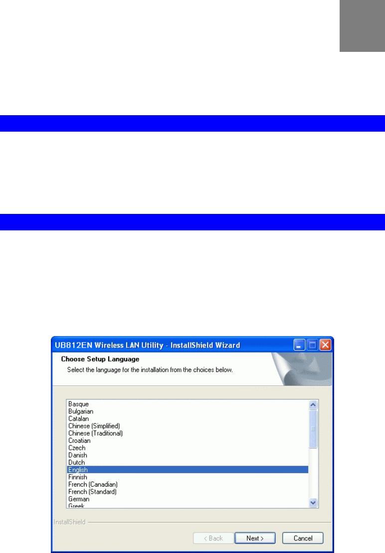
3. Select the desired setup language on the screen.
Figure 1: Start Installation
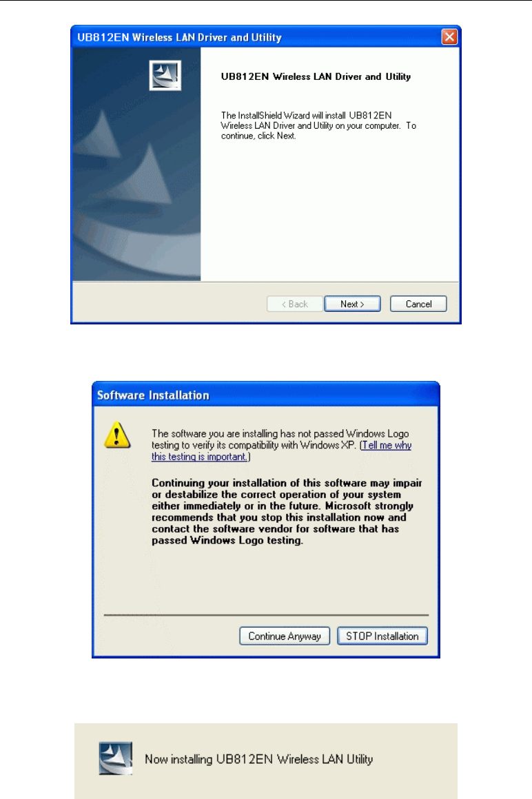
4. On the following screen, click "Next" to start the installation.
2
Wireless USB Adapter User Guide
4
Figure 2: Wireless LAN Driver and Utility Screen
5. Step though the procedure.
Figure 3: Installation Program
6. Click "Continue Anyway" on the screen above.
Figure 4: Information Screen
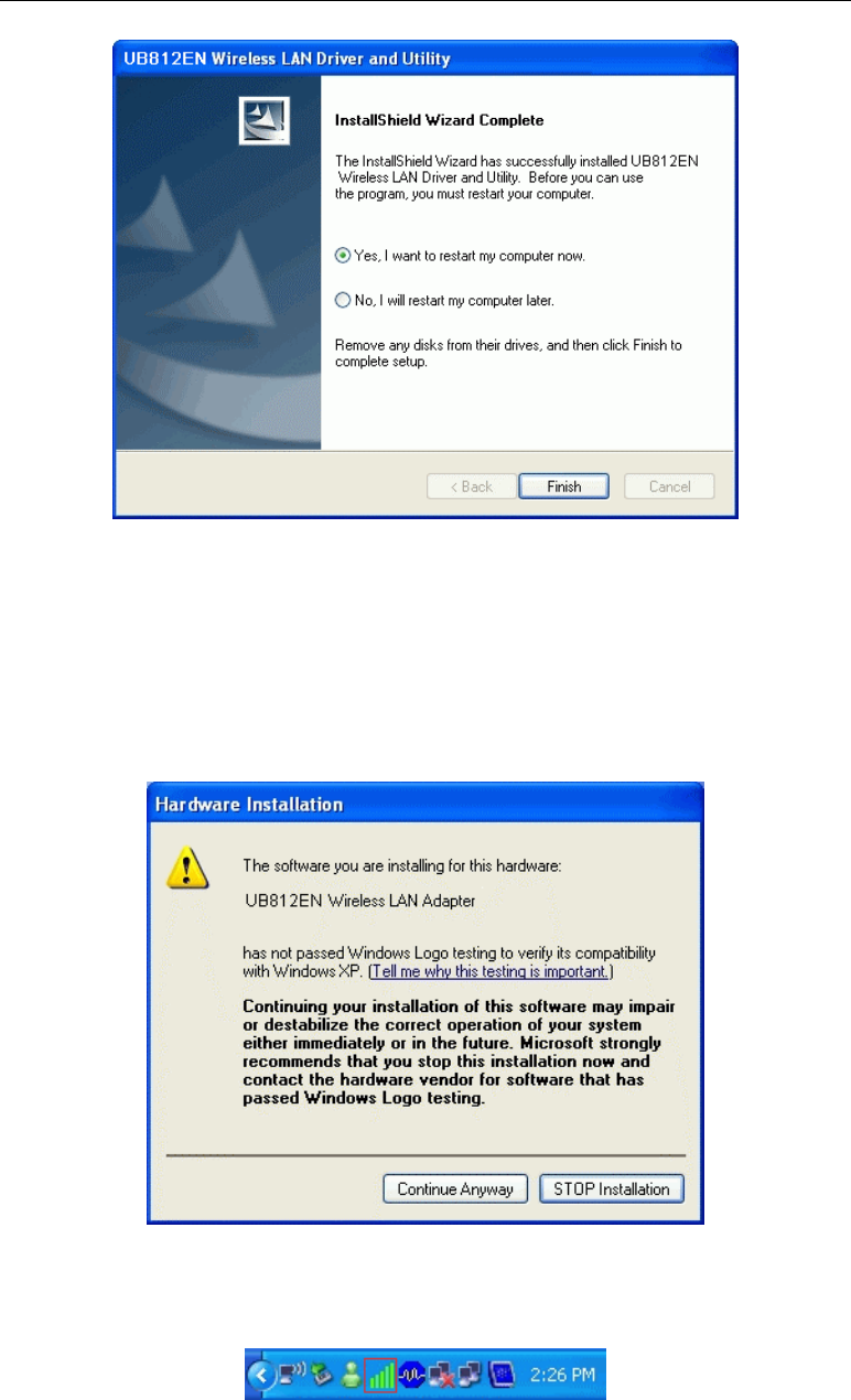
7. After the installation is complete, select Yes, I want to restart my computer now and then
click "Finish".
Initial Installation
5
Figure 5: Finish Screen
8. Insert the Wireless USB Adapter firmly into USB port of the PC.
9. The Windows "New Hardware" wizard will then start.
• Select Install the software automatically to allow it to complete the installation of the
Windows driver
• If using Windows XP, you may see a warning screen like the example below. If you
do see this screen, just click "Continue Anyway"
Figure 6: Windows XP Warning
10. If the Wireless USB Adapter was installed properly, you will now have a new icon in your
system tray, as shown below.
Figure 7: System Tray Icon

Wireless USB Adapter User Guide
6
Wireless USB Adapter Icon Table
Connection to the Wireless USB Adapter is established. The length of
green color indicates the signal strength.
No connection to the Wireless USB Adapter.
The Wireless USB Adapter is unplugged.
11. You can click this icon to configure the Wireless interface. See the following chapter for
details.

7
Chapter 3
Using the Windows Utility
This Chapter provides Setup details for the AP mode of the Wireless USB
Adapter.
Overview
If using Windows, you can use the supplied utility to configure the Wireless interface.
To Use the supplied Windows utility for Configuration
• Double-click the Wireless Utility icon in the desktop.
• Click Start - Programs - Sercomm - UB812EN - UB812EN Wireless LAN Utility.
This Chapter assumes you are using the supplied Wireless utility.
System Tray Icon
If the Wireless Utility program is running, you can click the icon in the System Tray or right-
click the icon and select "Open Config Utility" to open the application.
Status Information
The menu options available from the System Tray icon are:
• Open Config Utility - This will display the main screen of the Utility.
• About - Displays the information of company and version.
• Hide - This will remove the tray icon from the task bar.
• QUIT- Terminate the connection to the Wireless USB Adapter.
Figure 8: Wireless USB Adapter menu
3
Wireless USB Adapter User Guide
8
General Screen
This screen is displayed when you click the system tray icon. You can also click the General
tab in the screen.
When you open the utility program, it will scan all the channels to find all the access
points/stations within the accessible range and automatically connect to one of the wireless
devices which have the highest signal strength.
Figure 9: Network Screen
Data - Network Screen
Status Displays the current status of the Wireless LAN Adapter.
Speed It shows the current Transmission (Tx) rate and Receiving (Rx) rate.
Type This will indicate "Infrastructure" or "Ad-hoc".
Encryption It shows the wireless security that the wireless network is using.
SSID The SSID (up to 32 printable ASCII characters) is a unique name
identified in a WLAN.
Signal Strength This is displayed as percentage (0 ~ 100%) of specified network.
Link Quality It displays connection quality based on signal strength and TX/RX
packet error rate.
MAC Address This is the MAC address of the Access Point (or Wireless station, if
the network is an Ad-hoc network).
IP Address It shows the current IP address on the wireless interface.
Using the Windows Utility
9
Subnet Mask Subnet mask for the current IP address.
Gateway Gateway IP address associated with the current IP address.
Renew IP button Click this button to renew the IP address.
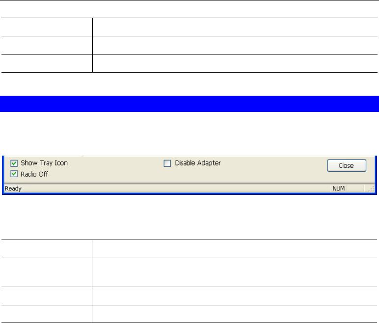
Adapter Settings
You can configure the adapter settings in this section.
Figure 10: Adapter Settings
Data - Adapter Settings
Show Tray Icon Enable this if you want the icon displayed in the task bar.
Disable Adapter Enable this to Terminate the connection to the Wireless USB
Adapter.
Radio Off You can turn the radio signal on/off by clicking this check box.
Close Button Click this button to exit the program.
Wireless USB Adapter User Guide
10
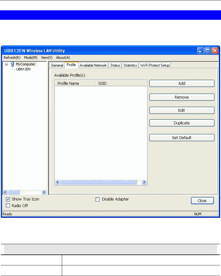
Profile Screen
Click Profile tab of the utility, then you will see the following screen. If you want to do the
general settings, please follow the instructions below.
Figure 10: Profile Screen
Data - Profile Screen
Available Profile(s)
Profile Name It will indicate the current name for this profile.
SSID If displays the SSID for the profile above.
To add a profile
1. On the Profile tab, click Add button.
2. Complete and verify the settings on this screen are correct.
3. Click OK.
To delete a profile
1. On the Profile tab, select the profile that you want to delete.
2. Click Remove.
To edit a profile
1. On the Profile tab, select the profile that you want to edit.
2. Click Edit button.

Using the Windows Utility
11
3. Change the profile settings as necessary.
4. Click OK.
To duplicate a profile
1. On the Profile tab, select the profile that you want to duplicate.
2. Click Duplicate.
3. Enter the name for the profile.
To enable a profile
1. In the list of available profiles, click the profile that you want to enable.
2. Click Set Default.
Wireless USB Adapter User Guide
12
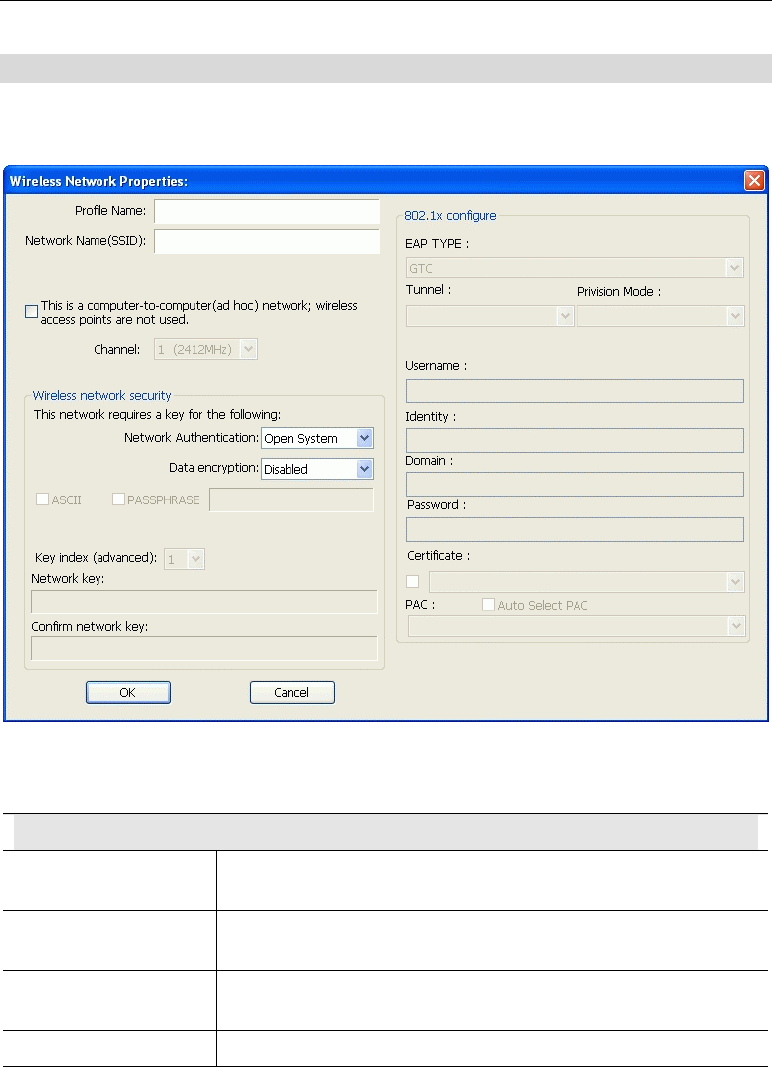
Add Profile
Click Add button in the Profile screen, the following Add Profile window will pop up. Users
can setup the general settings, encryption and authentication settings and so on.
Figure 11: Add Profile Screen
Data - Add Profile Screen
Wireless Network Properties
Profile Name Enter or select a suitable name for this profile. Each profile must
have a unique name.
Network Name
(SSID) Type in the SSID of the desired wireless network.
This is a computer-to-
computer network… Enable this if you are connecting directly to another computer.
Channel Select the Channel you wish to use on your Wireless LAN.

Using the Windows Utility
13
Wireless Network Security
Network
Authentication You MUST select the option to match the Wireless LAN you
wish to join. The available options are:
• Open System - Broadcast signals are not encrypted. This
method can be used only with no encryption or with WEP.
• Shared Key - Broadcast signals are encrypted using WEP.
This method can only be used with WEP.
• WPA-PSK - PSK means "Pre-shared Key". You must enter
this Passphrase value; it is used for both authentication and
encryption.
• WPA2-PSK - This is a further development of WPA-PSK,
and offers even greater security. You must enter this
Passphrase value; it is used for both authentication and en-
cryption.
• WPA 802.1x - This version of WPA requires a Radius
Server on your LAN to provide the client authentication ac-
cording to the 802.1x standard. Data transmissions are
encrypted using the WPA standard.
• WPA2 802.1x - This version of WPA2 requires a Radius
Server on your LAN to provide the client authentication ac-
cording to the 802.1x standard. Data transmissions are
encrypted using the WPA2 standard.
• WEP 802.1x - This version of WEP requires a Radius Server
on your LAN to provide the client authentication according
to the 802.1x standard. Data transmissions are encrypted us-
ing the WEP standard.
Data Encryption The available options depend on the Authentication method
selected above. The possible options are:
• Disabled - No data encryption is used.
• WEP - If selected, you must enter the WEP data shown
below. This WEP data must match the Access Point or other
Wireless stations.
• AES, TKIP - These options are available with WPA-PSK,
WPA2-PSK, WPA 802.1x and WPA2 802.1x. Select the cor-
rect option.
Passphrase For WEP modes, you need to enter the desired value (8~63
characters). Data is encrypted using a 256Bit key derived from
this key. Other Wireless Stations must use the same key.
Select the desired option, and ensure the Wireless Stations use the
same setting.
• 64 Bit - data is encrypted, using the default key, before being
transmitted. You must enter at least the default key. For 64
Bit Encryption, the key size is 10 chars in HEX (0~9 and
A~F).
• 128 Bit - data is encrypted, using the default key, before
being transmitted. You must enter at least the default key.
For 128 Bit Encryption, the key size is 26 chars in HEX (0~9
and A~F).

Wireless USB Adapter User Guide
14
ASCII Numerical values, characters or signs are all allowed to be
entered.
Key Index (1~4) This setting is only available for Open System or Shared Key
mode.
Network key For WPA-PSK and WPA2-PSK modes, you need to enter the
desired value (8~63 characters). Data is encrypted using a 256Bit
key derived from this key. Other Wireless Stations must use the
same key.
Confirm network key Re-enter the value in this field.
802.1x
EAP Method There are 5 methods in the drop-down list.
• GTC - Generic Token Card. It was created by Cisco. It
carries a text challenge from the authentication server, and a
reply which is assumed to be generated by a security token.
GTC does not protect the authentication data in any way.
• TLS - Transport Layer Security. Provides for certificate-
based and mutual authentication of the client and the net-
work. It relies on client-side and server-side certificates to
perform authentication and can be used to dynamically gen-
erate user-based and session-based WEP keys to secure
subsequent communications between the WLAN client and
the access point.
• LEAP - Lightweight Extensible Authentication Protocol. It
is a proprietary protocol from Cisco Systems developed to
address the security weaknesses common in WEP.
• TTLS - Tunneled Transport Layer Security. This security
method provides for certificate-based, mutual authentication
of the client and network through an encrypted channel.
Unlike EAP-TLS, EAP-TTLS requires only server-side cer-
tificates.
• PEAP - Protect Extensible Authentication Protocol. PEAP
transport securely authentication data by using tunneling be-
tween PEAP clients and an authentication server. PEAP can
authenticate wireless LAN clients using only server-side cer-
tificates, thus simplifying the implementation and
administration of a secure wireless LAN.
Tunnel Select the desired option from the drop-down list.
Provision Mode Select the desired mode from the drop-down list.
Username Enter the user name into the field.
Identity Enter the data in the field.
Domain Type the domain name you want into the field provided.
Password Enter the password for the tunnel.
Certificate Click the checkbox to enable certificate authority server function.
Select the desired option from the list.
PAC Select the desired option from the list.

Using the Windows Utility
15
Auto Select PAC Click the checkbox to select the PAC automatically.
Wireless USB Adapter User Guide
16
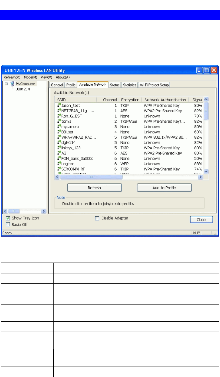
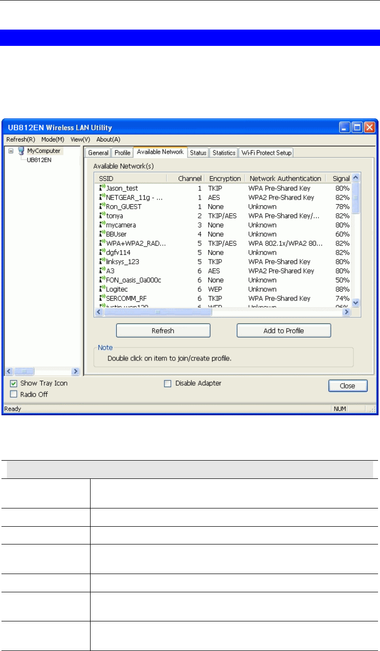
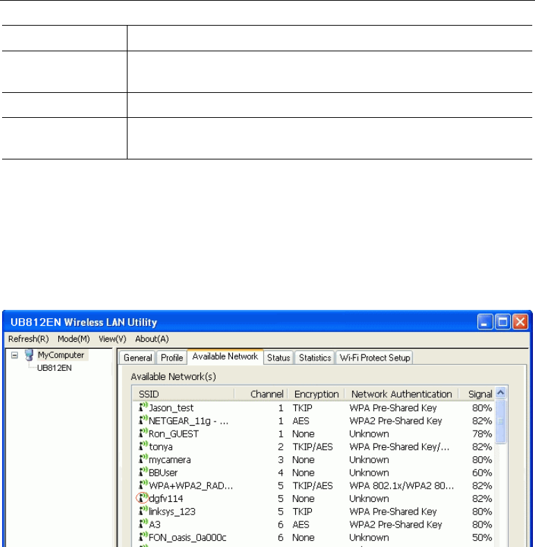
Available Network Screen
This screen is displayed when you click Available Network tab of the utility.
When you open the utility program, it will scan all the channels to find all the access
points/stations within the accessible range and automatically connect to one of the wireless
devices which have the highest signal strength.
Figure 12: Available Network Screen
Data - Available Network Screen
Available Network(s)
SSID The SSID (up to 32 printable ASCII characters) is a unique name
identified in a WLAN.
Channel The channel used by the Wireless network.
Encryption Data encryption used on the wireless network
Network
Authentication Data authentication methods used on the wireless network
Signal This is displayed as percentage (0 ~ 100%) of specified network.
Type It displays the Network type in use, Infrastructure for BSS, Ad-Hoc
for IBSS network.
BSSID This is the MAC address of the Access Point (or Wireless station, if
the network is an Ad-hoc network).
Using the Windows Utility
17
Supported Rates The Wireless rates supported by this Wireless network.
Mode AP support wireless mode. It may support 802.11a, 802.11b or
802.11n wireless mode.
Refresh Click this button to rescan for all Wireless networks.
Add to Profile Click this button to add the selected AP to Profile setting. It will bring
up profile page and save user's setting to a new profile.
To Connect to a Wireless Network
• Double Click the wireless network to which you want to connect
• Select the wireless network to which you want to connect, and then click Add to Profile.
Note that once you are connected to a Wireless network, the Available Network screen will
identify the current wireless network with a red circle, as shown below.
Figure 13: Available Network Screen - Connected
Wireless USB Adapter User Guide
18
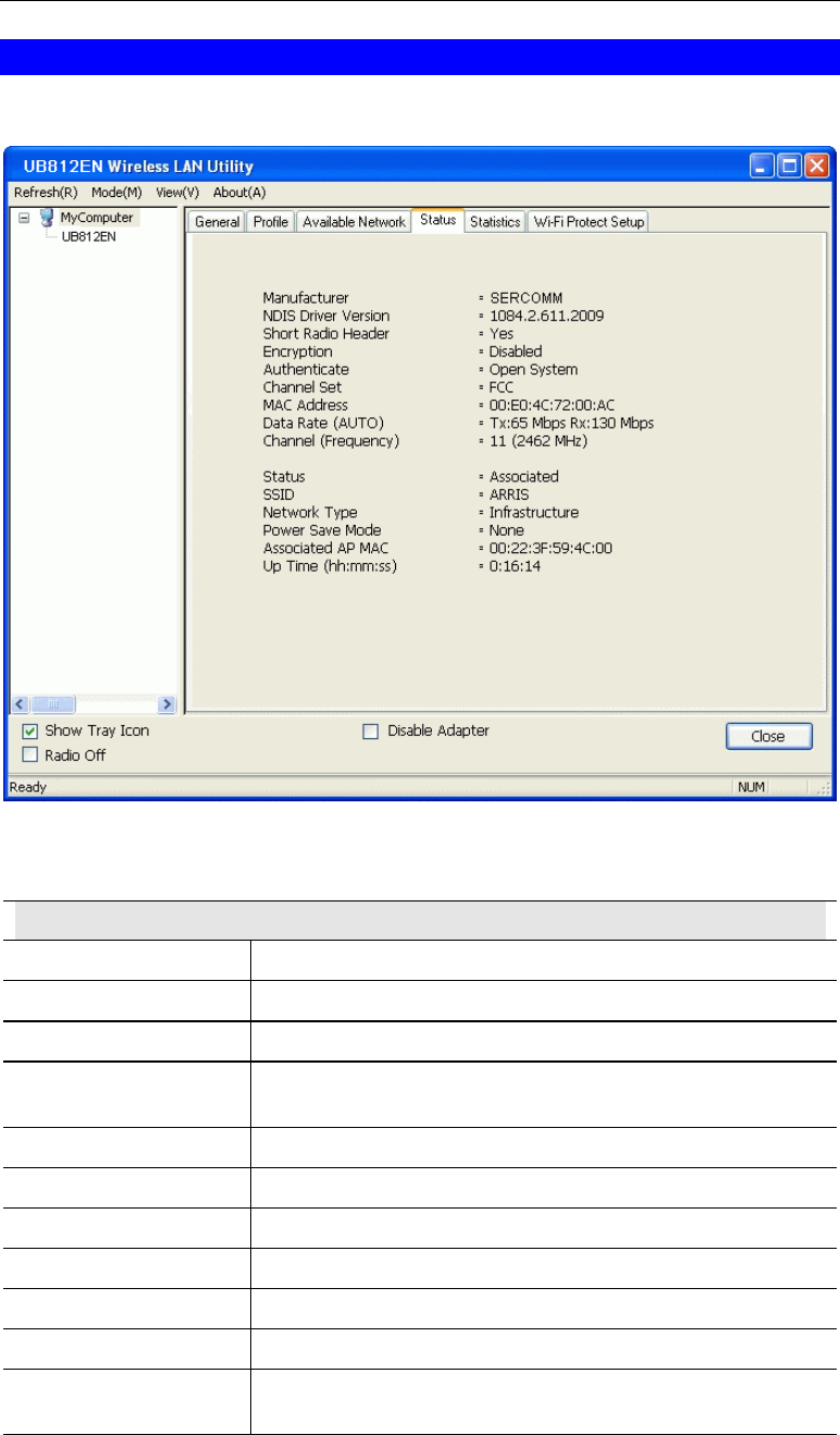
Status Screen
The Status screen displays the detailed information of the current connection.
Figure 10: Status Screen
Data - Status Screen
Status
Manufacturer It shows the manufacturer of the device
NDIS Driver Version It displays the current driver version of the NDIS.
Short Radio Header It indicates the current status of the short radio header.
Encryption It shows the wireless encryption that the wireless network is
using.
Authentication It will indicate the current authentication mode in use.
Channel Set It displays the current channel set.
MAC Address It shows the MAC address of the access point.
Date Rate It will show current transmit rate and receive rate.
Channel It displays the current channel in use.
Status It will indicate the current link status.
SSID It shows the SSID or network name of the selected wireless
network.

Using the Windows Utility
19
Channel It displays the current channel in use.
Network Type This will indicate "Infrastructure" or "Ad-hoc".
Power Save Mode It shows the current power save mode.
Associated AP MAC It shows the MAC address of the associated access point.
Up Time It displays the connection time.
Wireless USB Adapter User Guide
20
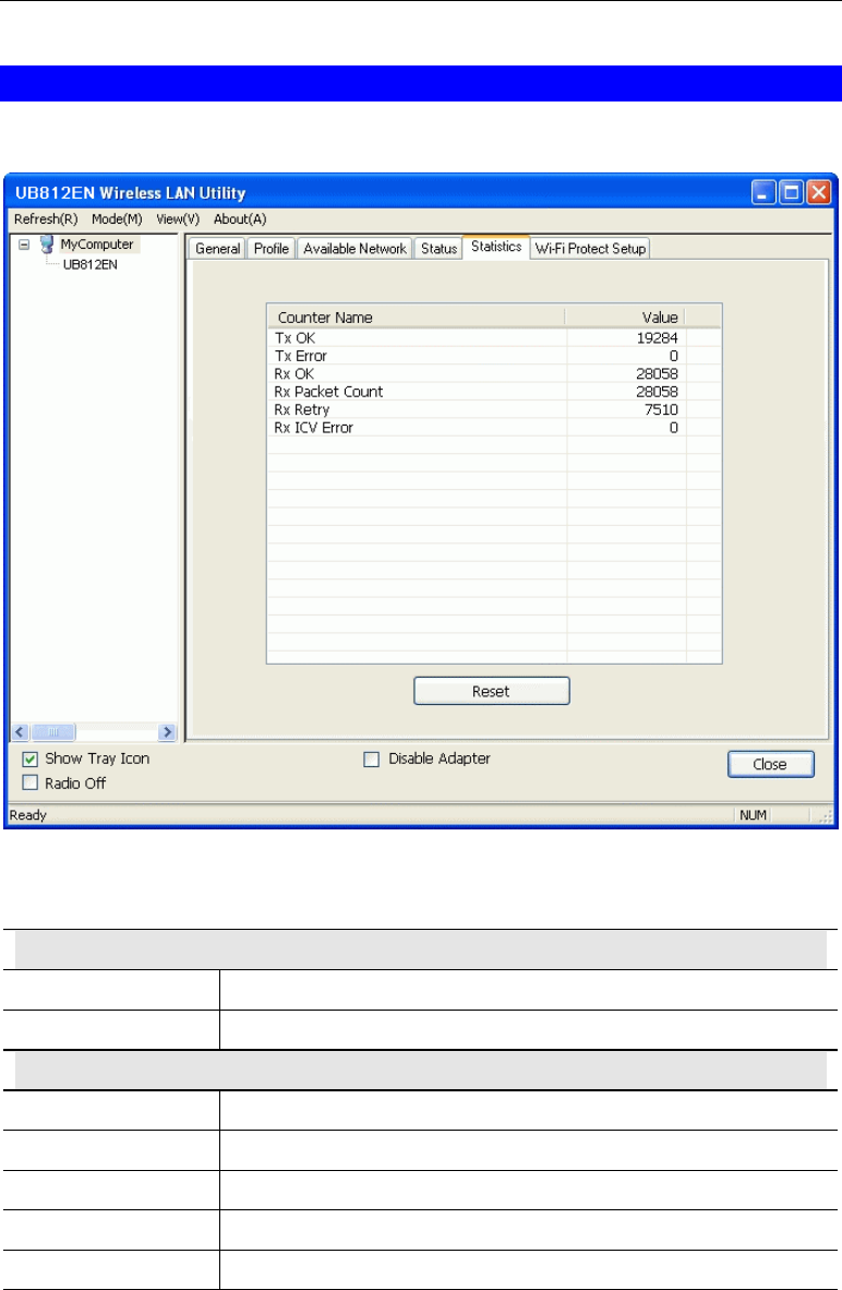
Statistics Screen
Click Statistics tab of the utility, the page will display the transmitted and received results.
Figure 14: Statistics Screen
Data - Statistics Screen
Transmit
Tx OK Frames successfully sent.
Tx Error Frames failed to transmit.
Receive
RX OK Frames received successfully.
Rx Packet Count Frames received with packet count.
Rx Retry Frames successfully received with one or more reties.
Rx ICV Error Frames received with ICV error.
Reset Click the button to reset counters to zero.
Using the Windows Utility
21
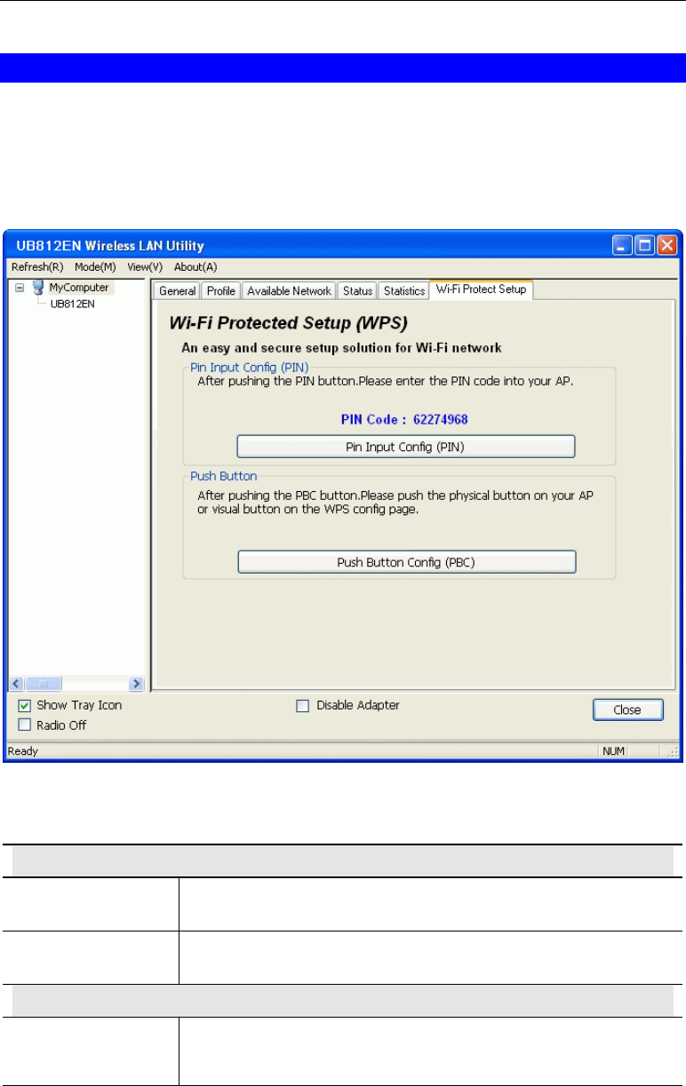
WPS Screen
WPS (Wi-Fi Protected Setup) can simplify the process of connecting any device to the wire-
less network by using the push button configuration (PBC) on the Wireless Access Point, or
entering a PIN code.
You will use the WPS screen when you try to connect the wireless network with the WPS
function.
Figure 15: WPS Screen
Data - WPS Screen
Pin Input config (PIN)
PIN Code Enter the PIN code displayed in the screen to the WPS screen of
the access point.
PIN Input config
(PIN) Button Click this button to connect to the selected network.
Push Button
Push Button Start to add to AP using PBC configuration method.
After clicking the Push Button Config (PBC), press the physical
button or the visual button on the WPS screen of the access point.

22
Appendix A
Specifications
Wireless USB Adapter
Standards: IEEE 802.11b, IEEE 802.11g, Draft 802.11n compliant
Computer Slot Type: USB
Chipset: RealtekRTL8191SU(MAC/BB/RF/PA)
LED: 1 LED: Link/Active
Tx: 1
Rx: 2
Date Rates:
20 MHz BW(LGI): 130, 117, 104, 78, 52, 39, 26, 13
40 MHz BW(LGI): 270, 243, 216, 162, 108, 81, 54, 27
802.11n: 20 MHz BW(SGI): 144, 130, 115.6, 86.7, 57.8, 43.3, 28.9, 14.4
40 MHz BW(SGI): 300, 270, 240, 180, 120, 90, 60, 30
802.11g: 54, 48, 36, 24, 18, 12, 9 and 6 Mbps
802.11b: 11, 5.5, 2 and 1 Mbps
Operating Channels: 11 for North America, 13 for Europe and Japan
Operating Frequency: 2.4 ~ 2.4835 GHz
Modulation Technique:
802.11n: BPSK, QPSK, 16-QAM, 64-QAM
802.11g: OFDM
802.11b: CCK,QPSK,BPSK
Media Access Protocol: CSMA/CA
Operating Voltage: 5V +/- 5%
Transmit Power:
802.11n: 13 +/- 1 dBm
802.11g: 13 +/- 1 dBm
802.11b: 17 +/- 1 dBm
Security: WPA/WPA2; 128-bit TKIP/AES encryption, 40/64-, 128-bit
WEP shared-key encryption
802.1x, and EAP-TLS, and PEAP authentication, WPS
OS Requirements: Windows Vista/XP/2000
A

23
Appendix B
About Wireless LANs
This Appendix provides some background information about using Wireless
LANs (WLANs).
Modes
Wireless LANs can work in either of two (2) modes:
• Ad-hoc
• Infrastructure
Ad-hoc Mode
Ad-hoc mode does not require an Access Point or a wired (Ethernet) LAN. Wireless Sta-
tions (e.g. notebook PCs with wireless cards) communicate directly with each other.
Infrastructure Mode
In Infrastructure Mode, one or more Access Points are used to connect Wireless Stations
(e.g. Notebook PCs with wireless cards) to a wired (Ethernet) LAN. The Wireless Stations
can then access all LAN resources.
Access Points can only function in "Infrastructure" mode,
and can communicate only with Wireless Stations which are
set to "Infrastructure" mode.
BSS/ESS
BSS
A group of Wireless Stations and a single Access Point, all using the same ID (SSID), form a
Basic Service Set (BSS).
Using the same SSID is essential. Devices with different SSIDs are unable to communicate
with each other.
ESS
A group of Wireless Stations, and multiple Access Points, all using the same ID (ESSID), form
an Extended Service Set (ESS).
Different Access Points within an ESS can use different Channels. In fact, to reduce interfer-
ence, it is recommended that adjacent Access Points SHOULD use different channels.
As Wireless Stations are physically moved through the area covered by an ESS, they will
automatically change to the Access Point which has the least interference or best performance.
This capability is called Roaming. (Access Points do not have or require Roaming capabilities.)
B

Wireless USB Adapter User Guide
24
Channels
The Wireless Channel sets the radio frequency used for communication.
• Access Points use a fixed Channel. You can select the Channel used. This allows you to
choose a Channel which provides the least interference and best performance. In the USA
and Canada, 11 channels are available. If using multiple Access Points, it is better if adja-
cent Access Points use different Channels to reduce interference.
• In "Infrastructure" mode, Wireless Stations normally scan all Channels, looking for an
Access Point. If more than one Access Point can be used, the one with the strongest signal
is used. (This can only happen within an ESS.)
• If using "Ad-hoc" mode (no Access Point), all Wireless stations should be set to use the
same Channel. However, most Wireless stations will still scan all Channels to see if there
is an existing "Ad-hoc" group they can join.
WEP & WPA-PSK
Both WEP and WPA-PSK are standards for encrypting data before it is transmitted.
This is desirable because it is impossible to prevent snoopers from receiving any data which is
transmitted by your Wireless Stations. But if the data is encrypted, then it is meaningless
unless the receiver can decrypt it.
WPA-PSK is a later standard than WEP, and is more secure.
WPA2-PSK
This is a later version of WPA (WPA-PSK). The major change is the use of AES (Advanced
Encryption System) for protecting data. AES is very secure, considered to be unbreakable. The
PSK (Pre-shared Key) must be entered on each Wireless station.
If WPA2-PSK is used, the Wireless Stations and the Access Point must have the same
settings for each of the following:
WPA2 PSK
(Pre-shared Key) Enter the same value on every station and the AP. The PSK
must be from 8 to 63 characters in length. The 256Bit key
used for the actual encryption is derived from this key.
Encryption The same encryption method must be used. The most
common encryption method is TKIP. Another widely-
supported method is AES.

Appendix B - About Wireless LANs
25
Wireless LAN Configuration
To allow Wireless Stations to use the Access Point, the Wireless Stations and the Access Point
must use the same settings, as follows:
Mode On client Wireless Stations, the mode must be set to "Infrastructure".
(The Access Point is always in "Infrastructure" mode.)
SSID (ESSID) Wireless Stations should use the same SSID (ESSID) as the Access
Point they wish to connect to. Alternatively, the SSID can be set to "any"
or null (blank) to allow connection to any Access Point.
Security The Wireless Stations and the Access Point must use the same settings
for Wireless security (Disabled, WEP, WPA-PSK, WPA2-PSK, WPA
8021.x, WPA2 802.1x, WEP 802.1x)
• If Wireless security remains disabled on the Access Point, all
stations must have wireless security disabled.
• If Wireless security is enabled on the Access Point, each station
must use the same settings.

Wireless USB Adapter User Guide
26
FCC Statement
This equipment has been tested and found to comply with the limits for a Class B
digital device, pursuant to Part 15 of the FCC Rules. These limits are designed to
provide reasonable protection against harmful interference in a residential installation.
This equipment generates, uses and can radiate radio frequency energy and, if not
installed and used in accordance with the instructions, may cause harmful interfer-
ence to radio communica-tions. However, there is no guarantee that interference will
not occur in a particular installation. If this equipment does cause harmful interference
to radio or television reception, which can be determined by turning the equipment off
and on, the user is encouraged to try to correct the interference by one of the following
measures:
Reorient or relocate the receiving antenna.
Increase the separation between the equipment and receiver.
Connect the equipment into an outlet on a circuit different from that to which the
receiver is connected.
Consult the dealer or an experienced radio/TV technician for help.
This device complies with part 15 of the FCC Rules.
Operation is subject to the following two conditions:
(1) This device may not cause harmful interference, and
(2) this device must accept any interference received, including interference that may cause
undesired operation.
IMPORTANT NOTE
To comply with RF exposure limits, user must not simultaneously operate wire-
lessproducts in adjacent USB-ports or cardbus slots.
This device has been SAR-evaluated for use with Laptop/Notebook computers and
meets the FCC RF exposure guidelines for an uncontrolled environment. 1.1W/kg.