Sercomm YN400 Home Monitoring Gateway User Manual Cardbus USB Wireless Adapter
Sercomm Corporation Home Monitoring Gateway Cardbus USB Wireless Adapter
Sercomm >
Users Manual
Home Monitoring
Gateway
User Guide

Table of Contents
CHAPTER 1 INTRODUCTION .............................................................................................1
Package Contents ..............................................................................................................1
Features..............................................................................................................................1
LEDs...................................................................................................................................2
CHAPTER 2 INITIAL INSTALLATION..............................................................................4
Requirements.....................................................................................................................4
Procedure...........................................................................................................................4
CHAPTER 3 BOARD DESCRIPTION ..................................................................................6
Overview ............................................................................................................................6
Components and connectors ............................................................................................6
Router/AP configuration ................................................................................................10
Copyright © 2008. All Rights Reserved.
Document Version: 1.0
All trademarks and trade names are the properties of their respective owners.
i

1
Chapter 1
Introduction
This Chapter provides an overview of the Home Monitoring Gateway's fea-
tures and capabilities.
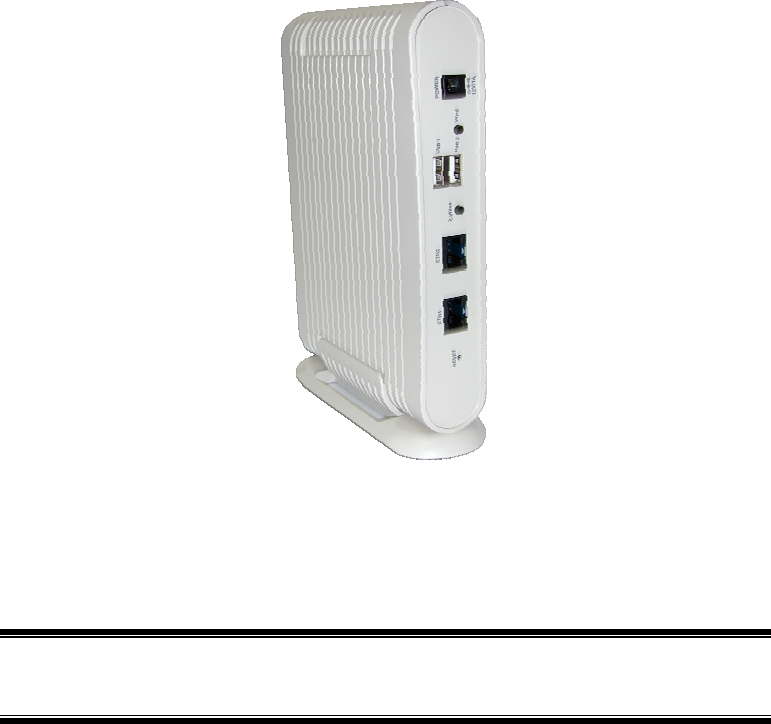
Congratulations on the purchase of your new Home Monitoring Gateway. The Home Monitor-
ing Gateway is a consumer electronic device, which is used for home monitoring and security.
Package Contents
The following items should be included:
• The Home Monitoring Gateway Unit
• Power Adapter
• A Stand
If any of the above items are damaged or missing, please contact your dealer immediately.
Features
• BCM5354 processor with16MB Flash and 32MB SDRAM
• Two Ethernet ports with RJ45 connectors.
• Front Panel LEDs
• Z-Wave Transceiver
• Two USB 2.0 ports
• WPS button
• Reset button
• Power In connector
• Internal antenna for WiFi and Z-Wave
1

Wireless Adapter User Guide
LEDs
Front-mounted LEDs
The Home Monitoring Gateway has 8 LEDs.
POWER • On (Green)- Power On
• Off - Power Off
• On (Amber) - POST (power on self test) failure or device malfunc-
tion
ETH (1~2)
(Green)
• On (Green)- LAN connection established.
• Off - No active connection on the corresponding LAN port.
• Flashing - Data is being transmitted or received via the corre-
sponding LAN (hub) port.
WiFi • On - Wireless connection available
• Off - No Wireless connection available.
• Flashing - Data is being transmitted or received via the Wireless
connection.
ZWave • On - ZWave function enabled.
• Off - ZWave function disabled.
• Flashing - Data is being transmitted or received via the Wireless
connection.
USB (1~2) • On (Green)- USB connection established.
• Off - No active connection on the corresponding USB port.
• Flashing - Data is being transmitted or received via the corre-
sponding USB port.
Service • On (Green)- Control Point has made a successful activation to the
Portal Server.
• Off - No active connection to the Portal Server.
• Flashing - Attempting to establish a connection to the Portal
Server.
2
Introduction
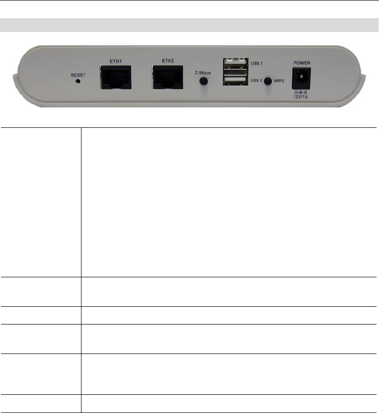
Rear Panel
Reset This button has two (2) functions:
• Reboot. When pressed and released, the Home Monitoring Gate-
way will reboot (restart).
• Clear All Data. This button can also be used to clear ALL data
and restore ALL settings to the factory default values.
To Clear All Data and restore the factory default values:
1. Power On.
2. Keep holding the Reset Button down for 8 seconds.
Release the Reset Button. The Home Monitoring Gateway is now using
the factory default values.
ETH (1~2) Port Use standard LAN cables (RJ45 connectors) to connect your PCs to
these ports.
Z-Wave Button Click this button to enable the Z-wave function.
USB (1~2) Port The two connectors are USB hosts with support for mass storage
devices.
WPS button Push the WPS button on the device and on your other wireless device to
perform WPS function that easily creates an encryption-secured wire-
less connection automatically.
Power Port Connect the supplied power adapter here.
3
2
Chapter 2
Initial Installation
This Chapter covers the software installation of the Home Monitoring Gate-
way.
Requirements
• Network cables. Use standard 10/100BaseT network (UTP) cables with RJ45 connectors.
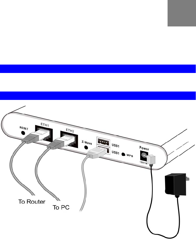
Procedure
1. Choose an Installation Site
Select a suitable place to install the Home Monitoring Gateway.
2. Connect LAN Cables
Use standard LAN cables to connect devices to the Ethernet ports on the Home Monitor-
ing Gateway.
4. Power Up
Connect the supplied power adapter to the Home Monitoring Gateway. Use only the
power adapter provided. Using a different one may cause hardware damage.
4

Initial Installation
5. Check the LEDs
• The POWER LED should be ON.
• The ETH LED should be ON (provided the PC is also ON.)
5
3
Chapter 3
Board Description
This Chapter provides board description for the Home Monitoring Gateway.
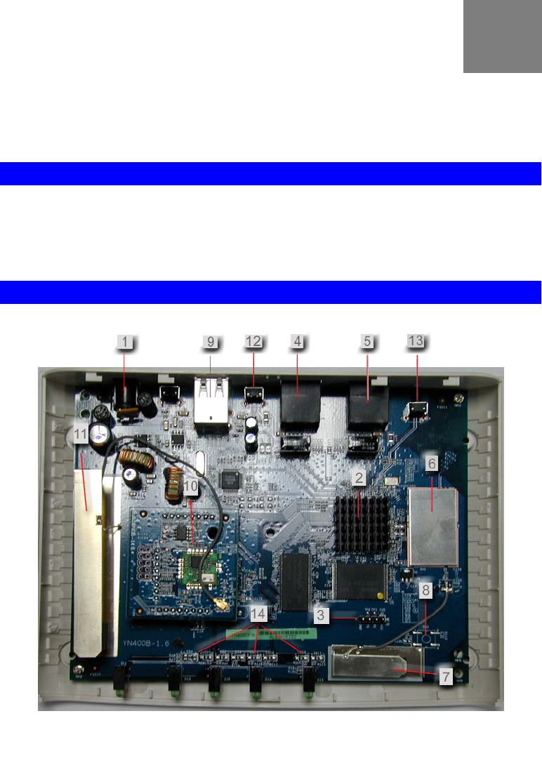
Overview
NA401 is a home gateway/automation, monitoring platform based on the Broadcom chip
BCM5354. Below is an image of the board showing different connection and interfaces.
Components and connectors
• 1 Power connector - The power jack connects to DC12V 1A power source.
• 2 BCM 5354 - The platform processor made by Broadcom.
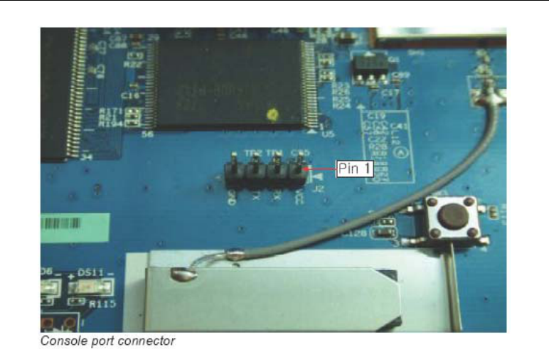
• 3 Console connector - The RS232 connector is used for debugging purpose. Note inter-
face voltage level is CMOS (3.3V), a logic level converter such as MAX232 will be
required.
Baud rate: 115200
Data bits: 8
Stop bits: 1
6

Appendix B - About Wireless LANs
Parity bit: none
Flow control: none
• 4 RJ-45 (1) connector - This is the LAN port connector with DHCP server function.
• 5 RJ-45 (2) connector - This is the WAN port connector.
• 6 WLAN PHY - This is the wireless LAN physical layer circuitry.
• 7 WLAN antenna - This is he antenna for wireless LAN.
• 8 WPS push button - This button is used for WPS function.
• 9 USB connector - The two connectors are USB hosts with support for mass storage
devices.
Currently, there is no auto detection for plugged in devices; the devices will need to be
manually mounted.
• 10 Z-Wave module - this is a Z-Wave static controller which can monitor/control other
Z-Wave based devices/sensors.
• 11 Z-Wave module antenna - This is the antenna for the Z-Wave module.
• 12 Push button 1 - this push button’s state is accessible via GPIO pin 4. If depressed
before system power on (or software reboot), system enters download mode. This mode is
used by SerComm during mass production, if board is accidentally booted into this mode,
power off than power back on.
• 13 Push button 2 - This push button’s state is accessible via GPIO pin 6. If depressed
before system power on (or software reboot), then release during boot up sequence, the
LAN, WAN and wireless LAN settings are restored to default value. However, GPIO pin
6 is also tied to RESET pin of the Z-Wave module. Hence, if push button 2 is depressed
during normal operation, Z-Wave functionality may behave unpredictably.
• 14 Programmable LED - These are seven single coloured and one bi-coloured LED
controllable by firmware.
Below is a close up of the console port. The pin definitions are:
Pin 1 - Vcc
Pin 2 - Receive
Pin 3 - Transmit
Pin 4 - Ground
7
Wireless Adapter User Guide
8
Appendix B - About Wireless LANs
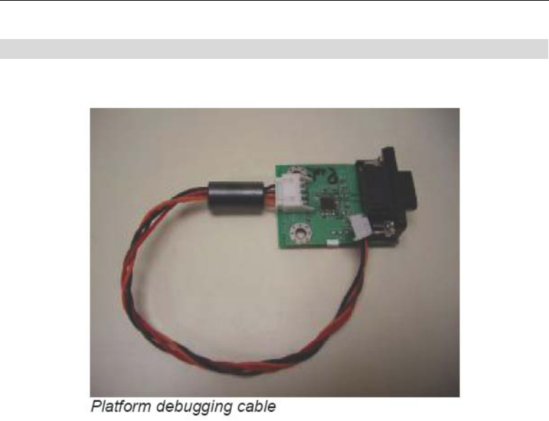
Console port connection guide
For platform debugging, please locate the console cable accompanied with the development kit.
9
Wireless Adapter User Guide
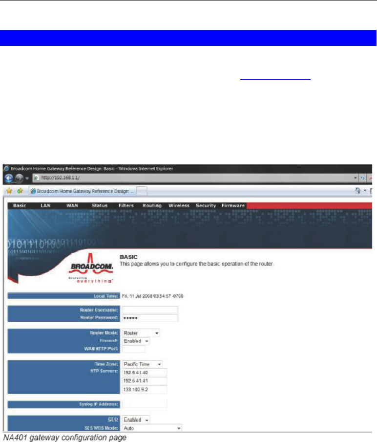
Router/AP configuration
To configure the gateway settings for the NA401, the user simply connects the host to the
LAN port. Then using Internet Explorer connect to the URL http://192.168.1.1
The default user name and password is:
User name: (blank)
Password: admin
The image below shows the configuration page once the user has entered the correct username
and password.
10

Class B Equipment
This equipment has been tested and found to comply with the limits for a Class B digital device, pursuant to
Part 15 of the FCC Rules. These limits are designed to provide reasonable protection against harmful inter-
ference in a residential installation. This equipment generates, uses, and can radiate radio frequency energy
and, if not installed and used in accordance with the instructions, may cause harmful interference to radio
communications. However, there is no guarantee that interference will not occur in a particular installation.
If this equipment does cause harmful interference to radio or television reception, which can be determined
by turning the equipment off and on, the user is encouraged to try to correct the interference by implementing
one or more of the following measures:
Relocate the unit and antenna (built-in)›
Increase the separation between the equipment and receiver›
Connect the equipment to an outlet on a circuit different from that to which the receiver is connected.›
Consult the dealer or experienced radio/TV technician for help›
0RGLêFDWLRQV
The FCC requires the user to be notified that any changes or modifications made to this device that are not
expressly approved by manufacturer, may void the user’s authority to operate the equipment.
Declaration of conformity for products marked with the FCC log – United States only.
This device complies with Part 15 of the FCC Rules. Operation is subject to the following two conditions:
This device may not cause harmful interferences, and1.
This device must accept any interference received, including interferences that may cause unwanted 2.
operation
FCC RF Radiation Exposure Statement:
1. This Transmitter must not be co-located or operating in conjunction with any other antenna or transmitter.
2. This equipment complies with FCC RF radiation exposure limits set forth for an uncontrolled environment. This equipment
should be installed and operated with a minimum distance of 20 centimeters between the radiator and your body.