Shark Sgp 3020 Users Manual
SGP-3530 to the manual 5f8c4ffe-90a0-490d-8552-97b8190fc3fb
2015-01-21
: Shark Shark-Sgp-3020-Users-Manual-220554 shark-sgp-3020-users-manual-220554 shark pdf
Open the PDF directly: View PDF ![]() .
.
Page Count: 34
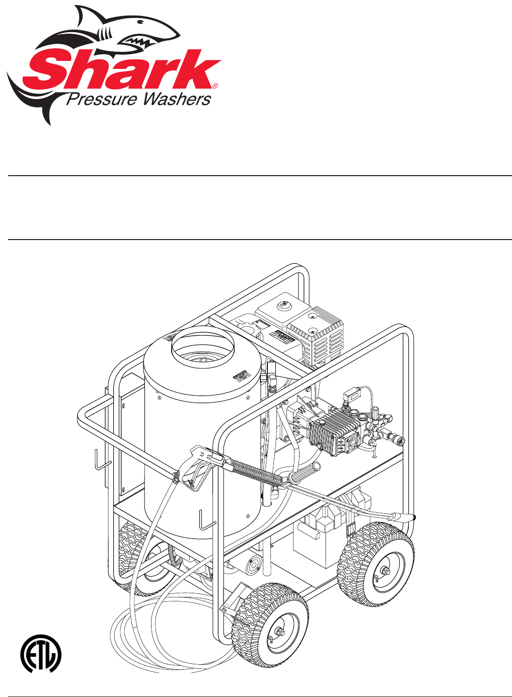
OPERATOR’S MANUAL
SGP
L
I
S
T
E
D
®
SGP-3020 SGP-3025 SGP-3030
SGP-3530 SGP-3530E SGP-4035E
For technical assistance or the SHARK dealer nearest you, call 1-360-833-9100,
1-800-771-1881 or visit our website at www.shark-pw.com
97-6132

3
CONTENTS
97-6132, 97-6151 • REV. 11/04
Model Number ______________________________________
Serial Number ______________________________________
Date of Purchase ____________________________________
The model and serial numbers will be found on a decal attached to
the pressure washer. You should record both serial number and date
of purchase and keep in a safe place for future reference.
Introduction & Important Safety Instructions 4-5
Component Identication 6
Assembly Instructions 7
Operating Instructions 8-9
Detergents and Cleaning Tips 10
Shut-Down and Clean Up 11
Storage 11
Maintenance 12-14
Troubleshooting 15-17
Maintenance & Oil Change Charts 18
Exploded View- 3020, 3025 19
Exploded View- 3030, 3530, 3530E, 4030E 20-21
Exploded View Parts Lists 22-24
Control Panel- 3020, 3025 & Parts List 25
Control Panel- 3030, 3530, 3530E, 4030E & Parts List 26-27
Hose & Spray Gun Assembly 28
Downstream Injector Assembly 29
Hose Reel Option 30
Burner Specications 31
Warranty
97-6132, 97-6151 • REV. 11/04
OPERATOR’S MANUAL PRESSURE WASHER
4
97-6132, 97-6151 • REV. 11/04
5
PRESSURE WASHER OPERATOR’S MANUAL
INTRODUCTION
Thank you for purchasing a Hot Water Pressure
Washer.
All information in this manual is based on the latest
product information available at the time of printing.
We reserves the right to make changes at any time
without incurring any obligation.
This series was designed for maximum use
of 4 hours per day, 5 days per week.
Owner/User Responsibility:
The owner and/or user must have an understanding of
the manufacturer’s operating instructions and warnings
before using this pressure washer. Warning information
should be emphasized and understood. If the operator
is not uent in English, the manufacturer’s instructions
and warnings shall be read to and discussed with
the operator in the operator’s native language by the
purchaser/owner, making sure that the operator com-
prehends its contents.
Owner and/or user must study and maintain for future
reference the manufacturers’ instructions.
This manual should be considered a permanent
part of the machine and should remain with it if
machine is resold.
When ordering parts, please specify model and
serial number.
IMPORTANT SAFETY
INSTRUCTIONS
WARNING: When using this machine basic pre-
cautions should always be followed, including the
following:
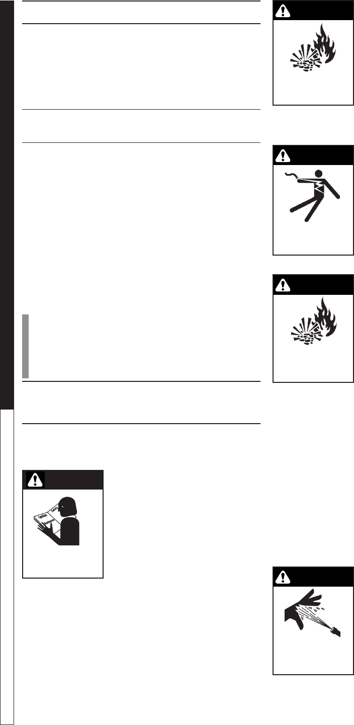
CAUTION: To reduce the risk of
injury, read operating instruc-
tions carefully before using.
1. Read the owner's manual
thoroughly. Failure to follow
instructions could cause mal-
function and result in death,
serious bodily injury and/or
property damage.
2. Know how to stop the machine and bleed pressures
quickly. Be thoroughly familiar with the controls.
3. Stay alert - watch what you are doing.
4. All installations must comply with local codes. Con-
tact your electrician, plumber, utility company or the
selling distributor for specic details.
WARNING: Flammable liquids
can create fumes which can
ignite causing property damage
or severe injury.
5. Risk of explosion - do not
spray flammable liquids or
operate in an explosive loca-
tion. Operate only where open
ame or torch is permitted.
WARNING: Do not place machine near ammable
objects when the engine is hot.
WARNING: Keep water spray
away from electrical wiring or
fatal electric shock may result.
WARNING: Spray gun kicks
back. Hold with both hands.
6. Grip cleaning wand securely
with both hands before start-
ing the cleaner. Failure to do
this could result in injury from
a whipping wand.
WARNING: Risk of re. Do not
add fuel when the machine is
operating.
7. Allow engine to cool for 2 min-
utes before refueling. If any
fuel is spilled, make sure area
is dry before testing spark plug
or starting the engine. (Fire
and/or explosion may occur
if this is not done.)
Gasoline engines on mobile or portable equipment
shall be refueled:
a. Outdoors;
b. With the engine on the equipment stopped;
c. With no source of ignition within 10 feet of the
dispensing point;
d. With an allowance made for expansion of the fuel
should the equipment be exposed to a higher
ambient temperature.
In an overlling situation, additional precautions are
necessary to ensure that the situation is handled
in a safe manner.
WARNING: Risk of injection or
severe injury to persons - Keep
clear of nozzle - Do not touch or
direct discharge stream at per-
sons. This machine is to be used
only by trained operators.
CAUTION: Hot discharge uid.
Do not touch or direct discharge
stream at persons.
WARNING
KEEP WATER SPRAY
AWAY FROM
ELECTRICAL WIRING.
WARNING
RISK OF EXPLOSION:
USE CAUTION WHEN
REFUELING.
READ OPERATOR’S
MANUAL THOROUGHLY
PRIOR TO USE.
CAUTION
WARNING
WARNING
RISK OF EXPLOSION:
DO NOT SPRAY FLAM-
MABLE LIQUIDS.
WARNING
HIGH PRESSURE
STREAM CAN
PIERCE SKIN AND
TISSUES.
97-6132, 97-6151 • REV. 11/04
OPERATOR’S MANUAL PRESSURE WASHER
4
97-6132, 97-6151 • REV. 11/04
5
PRESSURE WASHER OPERATOR’S MANUAL
8. High pressure developed by these machines can
cause personal injury or equipment damage. Use
caution when operating. Do not direct discharge
stream at people, or severe injury and/ or death
may result.
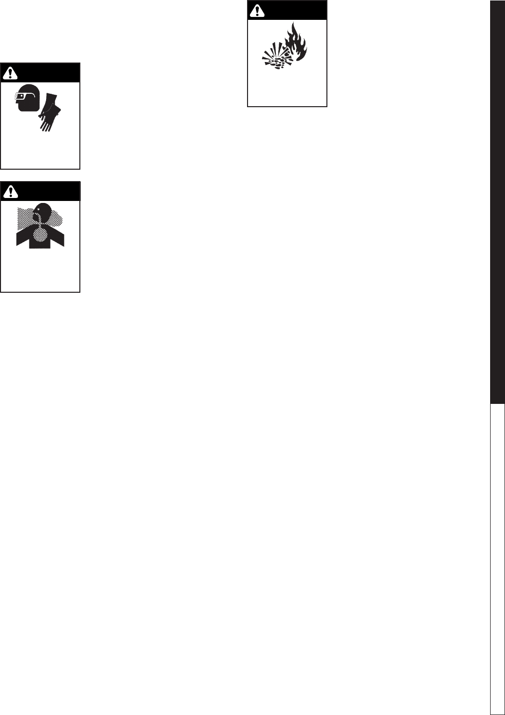
WARNING: High pressure can
cause paint chips or other par-
ticles to become airborne and y
at high speeds.
9. Eye safety devices and foot
protection must be worn when
using this equipment.
10. Never make adjustments on
machine while in operation.
WARNING: Use only in well ven-
tilated areas. Failure to observe
this warning could cause a loss
of consciousness or death. This
machine was designed for out-
door use only. Use high pressure
extension hose to clean indoors.
Store indoors.
11. Avoid installing in small areas
or near exhaust fans. Exhaust
contains poisonous carbon monoxide gas; exposure
may cause loss of consciousness and may lead to
death. It also contains chemicals known, in certain
quantities, to cause cancer, birth defects or other
reproductive harm.
12. Do not operate with the spray gun in the off posi-
tion for more than ve minutes as this may cause
damage to the pump.
13. The best insurance against an accident is pre-
caution and knowledge of the machine.
14. We will not be liable for any changes made to our
standard machines, or any components not pur-
chased from us.
15. Read engine safety instructions provided.
16. Never run pump dry or leave spray gun closed
longer than 5 minutes.
17. Inlet water must be from a cold, clean fresh city
water supply.
WARNING: Only use recom-
mended fuel. Using other fuels
may result in a serious explosion
causing personal injury, property
damage or loss of life.
18. Use No. 1 or No. 2 heating oil
(ASTM D306) only. NEVER
use gasoline in your fuel
oil tank. Gasoline is more
combustible than fuel oil
and could result in a serious explosion. NEVER use
crankcase or waste oil in your burner assembly.
Fuel pump malfunction could result from contami-
nation.
19. Do not confuse gasoline and fuel oil tanks. Keep
proper fuel in proper tank.
20. Protect machine from freezing.
21. Be certain all quick coupler ttings are secured
before using pressure washer.
22. Do not allow acids, caustic or abrasive uids to pass
through the pump.
23. To reduce the risk of injury, close supervision is nec-
essary when a product is used near children. Do not
allow children to operate the pressure washer. This
machine must be attended during operation.
24. Do not operate this product when fatigued or under
the inuence of alcohol or drugs. Keep operating
area clear of all persons.
25. Protect high pressure hose from vehicle trafc and
sharp objects.
26. Before disconnecting high pressure hose from wa-
ter outlet, turn burner off and pull the trigger on the
spray gun allowing water to cool to below 100° F
before stopping machine. Then open the spray gun
to relieve pressure. Failure to properly cool down
or maintain the heating coil may result in a steam
explosion and/or heating coil damage.
27. Do not overreach or stand on unstable support.
Keep good footing and balance at all times.
28. This machine must be attended during operation.
29. CAUTION: Risk of injury. Disconnect battery
ground terminal before servicing.
30. CAUTION: Moving this machine on a slope
causes instability and may result in machines
tipping over. Use lifting bar provided on the
center top of frame.
WARNING
USE PROTECTIVE
EYEWEAR WHEN
OPERATING.
WARNING
RISK OF FIRE OR EX-
PLOSION: USE VAPOR
FUEL ONLY.
WARNING
RISK OF
ASPHYXIATION.
USE THIS PRODUCT
ONLY IN A WELL
VENTILATED AREA.
97-6132, 97-6151 • REV. 11/04
OPERATOR’S MANUAL PRESSURE WASHER
6
97-6132, 97-6151 • REV. 11/04
7
PRESSURE WASHER OPERATOR’S MANUAL
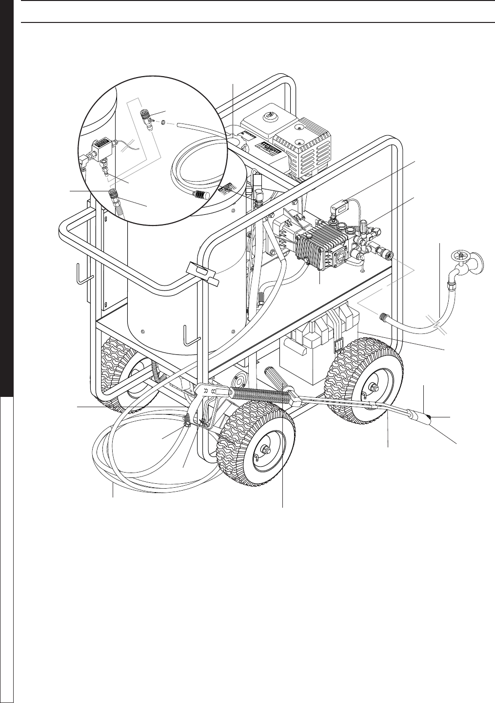
COMPONENT IDENTIFICATION
Pressure
Switch
Brass
Soap
Nozzle
Nozzle
Quick
Coupler
Spray Gun
High Pressure
Hose
Detergent
Injector
Quick
Coupler
Collar Discharge
Nipple
Water Supply
Hose
(not included)
Gasoline
Tank
Wand
Coupler
Variable Pressure
Control wand
Control Wand
Handle
Trigger
Swivel
Connector
Unloader
Battery Box
Pump — Develops high pressure.
Starter Grip — (Not Shown) Used for starting the
engine manually.
Spray Gun — Controls the application of water and
detergent onto cleaning surface with trigger device.
Includes safety latch.
Detergent Injector — Allows you to siphon and mix
detergents.
Variable Pressure Control Wand — Must be con-
nected to the spray gun. This wand handle controls
dishcharge ow from one tube to both wand tubes.
When water is discharged from both tubes you will have
a pressure loss and allows chemical siphoning when
used in combination with a detergent injector.
High Pressure Hose — Connect one end to water
pump discharge nipple and the other end to spray
gun.
Note: If trigger on spray gun is released for more than
2 minutes, water will leak from valve. Warm water will
discharge from pump protector onto oor. This system
prevents internal pump damage.
Pump
97-6132, 97-6151 • REV. 11/04
OPERATOR’S MANUAL PRESSURE WASHER
6
97-6132, 97-6151 • REV. 11/04
7
PRESSURE WASHER OPERATOR’S MANUAL
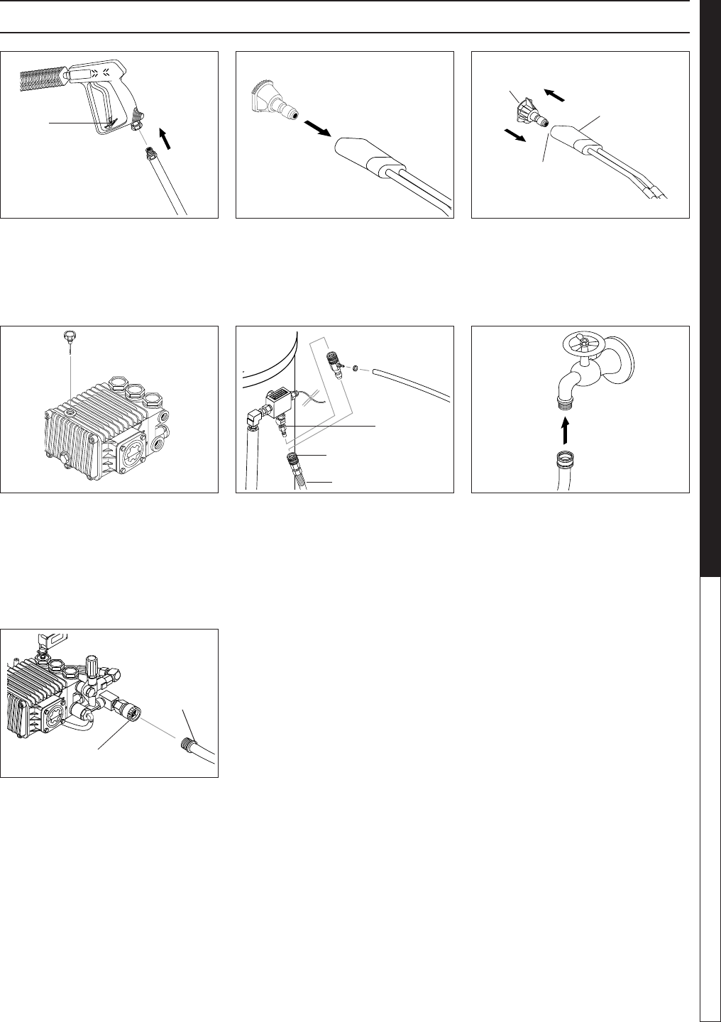
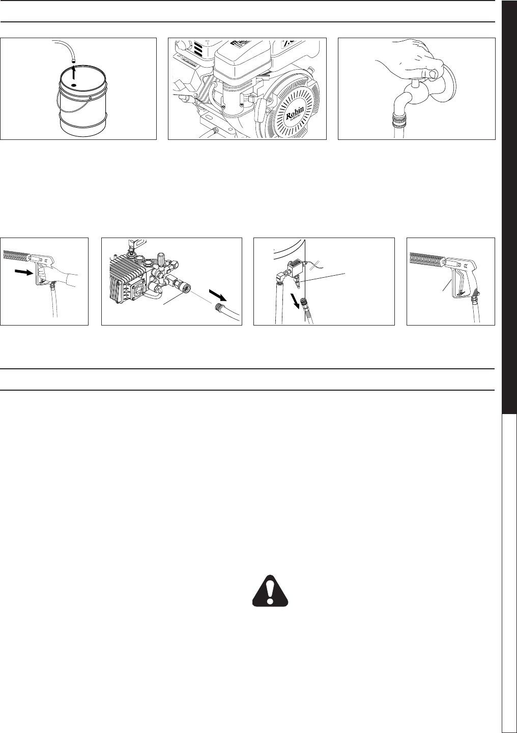
ASSEMBLY INSTRUCTIONS
STEP 1: Attach the high pressure
hose to the spray gun using teon
tape on hose threads.
STEP 3: Release the coupler collar
and push the nozzle until the collar
clicks. Pull the nozzle to make sure
it is seated properly.
STEP 5: Connect the high pres-
sure hose to the pump discharge
tting. Push coupler collar forward
until secure.
STEP 2: Pull the spring-loaded
collar of the wand coupler back
to insert your choice of pressure
nozzle.
STEP 6: Connect garden hose to
the cold water source.
STEP7: Connect the garden hose
to pump water inlet. Inspect inlets.
CAUTION: Do not run the pump
without water or pump damage
will result.
Safety
Latch
Spray
Gun
High Pressure
Hose
Wand
Coupler
Soap
Nozzle
Pressure
Nozzle
Wand
Coupler
Wand
Collar
Discharge
Fitting
High Pressure Hose
Cold
Water
Source
Garden
Hose
Pump
Water Inlet
Garden
Hose
Coupler Collar
DipStick
STEP 4: Remove shipping cap and
install oil dipstick. Check pump oil
level by using dipstick or observe
oil level in oil window (if equipped).
Use 30 wt. non detergent oil.
97-6132, 97-6151 • REV. 11/04
OPERATOR’S MANUAL PRESSURE WASHER
8
97-6132, 97-6151 • REV. 11/04
9
PRESSURE WASHER OPERATOR’S MANUAL
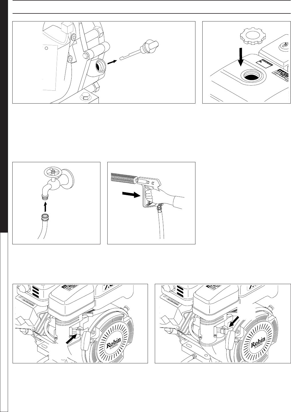
OPERATING INSTRUCTIONS
STEP 1: Check engine oil level. Oil level should be level with the bottom
of the oil ller neck. Be sure the machine is level when checking the oil
level. (Refer to the engine's operating manual included with machine.)
We recommend that the oil be changed after the rst 5 hours of use, then
once every 50 hours. Note: Improper oil levels will cause low oil sensor
to shut off engine. IMPORTANT! Do not run engine with high or low
oil levels as this will cause engine damage.
STEP 3: Connect garden hose to the
cold water source and turn water on
completely. Never use hot water.
STEP 5: Rotate the fuel shut-off valve to the "On" po-
sition. Slide the fuel valve lever to the "ON" position.
When the engine is not in use, leave the fuel valve in
the "OFF" position.
STEP 4: Trigger the spray gun to
eliminate trapped air then wait for a
steady ow of water to emerge from
the spray nozzle.
STEP 2: Fill gas tank with unleaded
gasoline. Do not use leaded gas-
oline. Caution: Read warnings
on pg. 4 and engine manual.
STEP 6: Pull the choke lever out to the "Choke" po-
sition (on a warm engine, leave the choke lever in, in
the run position). Push the choke lever to the "Closed"
position. To restart a warm engine, leave the choke
lever in the "Open" position.
Oil Dipstick Gas
Tank
Cold
Water
Source
Garden
Hose
Choke
Lever
Fuel
Valve
97-6132, 97-6151 • REV. 11/04
OPERATOR’S MANUAL PRESSURE WASHER
8
97-6132, 97-6151 • REV. 11/04
9
PRESSURE WASHER OPERATOR’S MANUAL
Safety
Latch
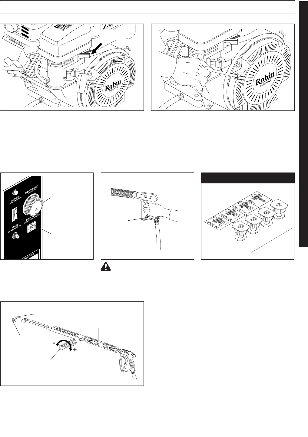
STEP 7: Turn the engine to "Run" position. STEP 8: Pull the starter grip. If the engine fails to start
after 2 pulls, squeeze the trigger gun to release pres-
sure and repeat step. Return starter gently. After the
engine warms up enough to run smoothly, move choke
to run position and throttle to fast position.
CAUTION: Small engines may kick back. Do not
hold pull starter grip tightly in hand.
WARNING! Never replace
nozzles without engaging the
safety latch on the spray gun
trigger.
The four color-coded quick con-
nect nozzles provide a wide array
of spray widths from 0° to 45° and
are easily accessible when placed in
the convenient rubber nozzle holder,
which is provided on the front of the
machine.
NOTE: For a more gentle rinse,
select the white 40° or green 25°
nozzle. To scour the surface, select
the yellow 15° or red 0° nozzle. To
apply detergent select the black
nozzle.
NOZZLES
Throttle
Temperature
Gauge
Burner
Switch
STEP 8: If hot water is required.
Adjust temperature gauge to proper
temperature (200°). Turn on Burner
switch to begin heating water.
Selection of high or low pressure is accompanied by
turning the handle. Note: High pressure nozzle must
be inserted at end of wand to obtain high pressure. To
apply soap read operator's manual.
Variable Pressure
Control Handle Trigger
Variable Pressure
Wand (VP)
High
Pressure
Nozzle
Brass Soap
Nozzle
OPERATING INSTRUCTIONS
97-6132, 97-6151 • REV. 11/04
OPERATOR’S MANUAL PRESSURE WASHER
10
97-6132, 97-6151 • REV. 11/04
11
PRESSURE WASHER OPERATOR’S MANUAL
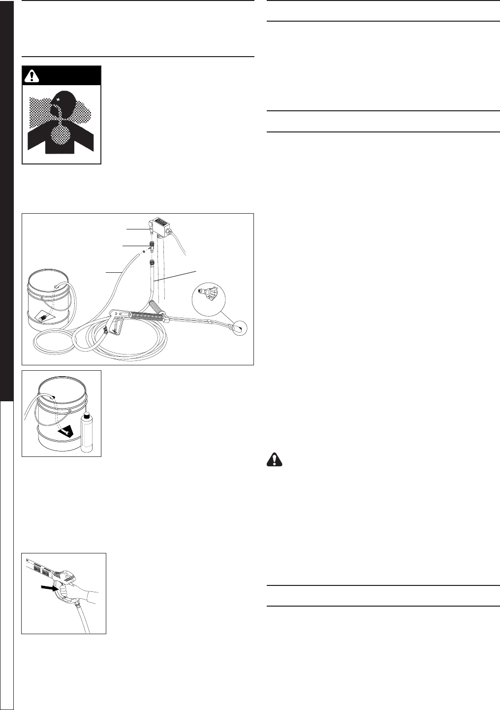
WARNING: Some detergents
may be harmful if inhaled or in-
gested, causing severe nausea,
fainting or poisoning. The harm-
ful elements may cause property
damage or severe injury.
STEP 1: Connect detergent
injector to discharge nipple on
machine, Connect high pressure
hose to injector with quick coupler (check to make sure
locking coupler sleeves are in proper position before
applying water pressure.
STEP 2: Use detergent designed
specically for pressure washers.
Household detergents could dam-
age the pump. Prepare detergent
solution as required by the manu-
facturer. Fill a container with pres-
sure washer detergent. Place the
lter end of detergent suction hose
into the detergent container.
STEP 3: Apply safety latch to spray gun trigger. Turn
variable pressure control handle until discharge water
exits both tubes. Secure black detergent nozzle into
quick coupler if you have a single wand. NOTE: De-
tergent cannot be applied using Red, Yellow, Green or
White nozzles.
STEP 3: With the engine running,
pull trigger to operate machine.
Liquid detergent is drawn into the
machine and mixed with water.
Apply detergent to work area.
Do not allow detergent to dry on
surface.
IMPORTANT: You must ush the detergent injection
system after each use by placing the suction tube
into a bucket of clean water, then run the pressure
washer in low pressure for 1-2 minutes.
THERMAL PUMP PROTECTION
If you run the engine on your pressure washer for 3-5
minutes without pressing the trigger on the spray gun,
circulating water in the pump can reach high tempera-
tures. When the water reaches this temperature, the
pump protector engages and cools the pump by dis-
charging the warm water onto the ground. This thermal
device prevents internal damage to the pump.
CLEANING TIPS
Pre-rinse cleaning surface with fresh water. Place de-
tergent suction tube directly into cleaning solution and
apply to surface at low pressure (for best results, limit
your work area to sections approximately 6 feet square
and always apply detergent from bottom to top). Allow
detergent to remain on surface 1-3 minutes. Do not al-
low detergent to dry on surface. If surface appears to
be drying, simply wet down surface with fresh water. If
needed, use brush to remove stubborn dirt. Rinse at
high pressure from top to bottom in an even sweeping
motion keeping the spray nozzle approximately 1 foot
from cleaning surface. Use overlapping strokes as you
clean and rinse any surface. For best surface cleaning
action spray at a slight angle.
Recommendations:
• Before cleaning any surface, an inconspicuous
area should be cleaned to test spray pattern and
distance for maximum cleaning results.
• If painted surfaces are peeling or chipping, use
extreme caution as pressure washer may remove
the loose paint from the surface.
• Keep the spray nozzle a safe distance from the
surface you plan to clean. High pressure wash a
small area, then check the surface for damage. If
no damage is found, continue to pressure wash-
ing.
CAUTION - Never use:
• Bleach, chlorine products and other corrosive
chemicals
• Liquids containing solvents (i.e., paint thinners,
gasoline, oils)
• Tri-sodium phosphate products
• Ammonia products
• Acid-based products
These chemicals will harm the machine and will dam-
age the surface being cleaned.
RINSING
It will take a few seconds for the detergent to clear.
Apply safety latch to spray gun. Remove black soap
nozzle from the quick coupler. Select and install the
desired high pressure nozzle. NOTE: You can also stop
detergent from owing by simply removing detergent
siphon tube from bottle.
WARNING
APPLYING DETERGENT
AND GENERAL OPERATING
TECHNIQUES
Disharge Nipple
Detergent Injector High
Pressure
Hose
Detergent
Suction
Hose
97-6132, 97-6151 • REV. 11/04
OPERATOR’S MANUAL PRESSURE WASHER
10
97-6132, 97-6151 • REV. 11/04
11
PRESSURE WASHER OPERATOR’S MANUAL
SHUTTING DOWN AND CLEAN-UP
CAUTION: Always store your pressure washer in a
location where the temperature will not fall below
32°F (0°C). The pump in this machine is susceptible
to permanent damage if frozen. FREEZE DAMAGE
IS NOT COVERED BY WARRANTY.
1. Stop the pressure washer, squeeze spray gun trig-
ger to release pressure.
2.
Detach water supply hose and high pressure hose.
3. Turn on the machine for a few seconds, until re-
maining water exits. Turn engine off immediately.
4. Drain the gas and oil from the engine.
5.
Do not allow high pressure hose to become kinked.
6. Store the machine and accessories in a room which
does not reach freezing temperatures.
CAUTION: Failure to follow the above directions will
result in damage to your pressure washer.
When the pressure washer is not being operated or is
being stored for more than one month, follow these
instructions:
1. Replenish engine oil to upper level.
2. Drain gasoline from fuel tank, fuel line, fuel valve
and carburetor.
3. Pour about one teaspoon of engine oil through
the spark plug hole, pull the starter grip several
times and replace the plug. Then pull the starter
grip slowly until you feel increased pressure which
indicates the piston is on its compression stroke and
leave it in that position. This closes both the intake
and exhaust valves to prevent rusting of cylinder.
4.
Cover the pressure washer and store in a clean, dry
place that is well ventilated away from open ame
or sparks. NOTE: The use of a fuel additive, such as
STA-BIL®, or an equivalent, will minimize the formu-
lation of fuel deposits during shortage. Such additives
may be added to the gasoline in the fuel tank of the
engine, or to the gasolinee in a storage container.
After Extended Storage
CAUTION: Prior to restarting, thaw out any
possible ice from pressure washer hoses,
spray gun or wand.
Engine Maintenance
During the winter months, rare atmosheric conditions
may develop which will cause an icing condition in the
carburetor. If this develops, the engine may run rough,
lose power and may stall. This temporary condition can
be overcome by deecting some of the hot air from the
engine over the carburetor area. NOTE: Refer to the
engine manufacturer's manual for service and mainte-
nance of the engine.
STORAGE
STEP 1: Remove detergent suction
tube from container and insert into
1 gallon of fresh water. Turn variable
pressure wand handle for low pres-
sure or connect the black detergent
nozzle. Pull trigger on spray gun and
siphon water for one minute.
STEP 2: Turn off the engine. STEP 3: Turn off water
supply.
STEP 5: Disconnect the garden
hose from the water inlet on the
machine.
STEP 6: Disconnect the high
pressure hose from high pres-
sure outlet.
STEP 7: Engage
the spray gun
safety lock.
STEP 4: Press trig-
ger to release water
pressure.
Water Inlet
High Pressure
Outlet
Safety
Latch

97-6132, 97-6151 • REV. 11/04
OPERATOR’S MANUAL PRESSURE WASHER
12
97-6132, 97-6151 • REV. 11/04
13
PRESSURE WASHER OPERATOR’S MANUAL
PREVENTATIVE
MAINTENANCE
1. Check to see that the water pump is properly lubri-
cated.
2. Follow Winterizing Procedures to prevent freeze
damage to the pump and coils.
3. Always neutralize and ush detergent from system
after use.
4. If water is known to be high in mineral content, use
a water softener in your water system or de-scale
as needed.
5. Do not allow acidic, caustic or abrasive uids to be
pumped through system.
6. Always use our high grade quality cleaning prod-
ucts.
7. Never run pump dry for extended periods of time.
8. Use clean fuel: kerosene, No. 1 fuel oil or diesel.
Replace fuel lter every 100 hours of operation.
Avoid water contaminated fuel as it will seize up
the fuel pump.
9. If machine is operated with smoking or eye burning
exhaust, coils will soot up, not letting water reach
maximum operating temperature. (See section on
Air Adjustments.)
10. Never allow water to be sprayed on or near engine
or burner assembly or any electrical component.
11. Periodically delime coils as per instructions.
12. Check to see that engine is properly lubricated.
It is advisable, periodically, to visually inspect the burner.
Check air inlet to make sure it is not clogged or blocked.
Wipe off any oil spills and keep this equipment clean
and dry.
The areas around the pressure washer should be kept
clean and free of combustible materials, gasoline and
other ammable vapors and liquids.
The ow of combustion and ventilating air to the burner
must not be blocked or obstructed in any manner. Con-
sult factory if vent stacking is going to be used.
MAINTENANCE AND SERVICE
Unloader Valves:
Unloader valves are preset and tested at the factory
before shipping. Occasional adjustment of the unloader
may be necessary to maintain correct pressure. Call
your local dealer for assistance.
Winterizing Procedure:
Damage due to freezing is not covered by warranty. Ad-
here to the following cold weather procedures whenever
the washer must be stored or operated outdoors under
freezing conditions.
During winter months, when temperatures drop below
32°F, protecting your machine against freezing is nec-
essary. Store the machine in a heated room. If this is not
possible then mix a 50/50 solution of anti-freeze/water
into a 5 gallon bucket. Place a short section of garden
hose into the bucket and connect it to the machine.
Elevate the bucket and turn the pump on to siphon the
anti-freeze through the machine. If compressed air is
available, an air tting can be screwed into the inlet
connector and, by injecting compressed air, all water
will be blown out of the system.
High Limit Hot Water Thermostat:
For safety, each machine is equipped with a high limit
control switch. In the event that the temperature of the
water should exceed its operating temperature, the
high limit control will turn the burner off until the water
cools.
Pumps:
Use only SAE 30W non-detergent oil. Change oil after
the rst 50 hours of use. Thereafter, change the oil every
three months or at 500 hour intervals. Oil level should be
checked by using the dipstick found on top of the pump
or the red dot visible through the oil gauge window. Oil
should be maintained at that level.
Cleaning of Coils:
In alkaline water areas, lime deposits can accumulate
rapidly inside the coil pipes. This growth is increased by
the extreme heat build up in the coil. The best prevention
for liming conditions is to use high quality cleaning de-
tergents. In areas where alkaline water is an extreme
problem, periodic use of our Deliming Powder (part
#9-028008) will remove lime and other deposits before
coil becomes plugged. (See Deliming Instructions for
use of Deliming Powder.)
Deliming Coils:
Periodic ushing of coils is recommended.
1. Fill a container or optional oat tank with 4 gallons
of water, then add 1 lb. of deliming powder. Mix
thoroughly.
2. Remove wand assembly from spray gun and put
spray gun into container. Secure the trigger on the
spray gun into the open position.
3. Attach a short section (3-5 ft.) of garden hose to
machine to siphon solution from an elevated con-
tainer. Turn pump switch on, allowing solution to
be pumped through coils back into the container.
Solution should be allowed to circulate 2-4 hours.
4. After circulating solution ush entire system with
fresh water. Reinstall wand assembly to spray gun.
MAINTENANCE
97-6132, 97-6151 • REV. 11/04
OPERATOR’S MANUAL PRESSURE WASHER
12
97-6132, 97-6151 • REV. 11/04
13
PRESSURE WASHER OPERATOR’S MANUAL
Rupture Disk:
If pressure from pump or thermal expansion should
exceed safe limits, the rupture disk will burst allow-
ing high pressure to be discharged through hose to
ground. When disk ruptures it will need to be replaced.
The replacement rupture disk should be torqued to 35
ft. lbs.
Fuel:
Use clean fuel oil that is not contaminated with water
and debris. Replace fuel lter and drain tank every 100
hours of operation.
Use No. 1 or No. 2 Heating Oil (ASTM D306) only.
NEVER use gasoline in your burner tank. Gasoline is
more combustible than fuel oil and a serious explo-
sion could result. NEVER use crankcase or waste oil
in your burner. Fuel unit malfunction could result from
contamination.
Fuel Control System:
These machines utilize a fuel solenoid valve located
on the fuel pump to control the ow of fuel to the com-
bustion chamber. This solenoid valve, which is normally
closed, is activated by a ow switch when water is ow-
ing through it. When an operator releases the trigger on
the spray gun, the ow of water through the ow switch
stops, turning off the current to the fuel solenoid. The
solenoid then closes, shutting off the supply of fuel to
the combustion chamber. Controlling the ow of fuel in
this way allows for an instantaneous burn or no burn
situation, thereby eliminating high and low water tem-
peratures, and combustion smoke normally associated
with machines incorporating a spray gun.
CAUTION: Periodic inspection is recommended to in-
sure that the fuel solenoid valve functions properly. This
can be done by operating the machine and checking to
see that when the trigger on the spray gun is in the off
position, the burner is not ring.
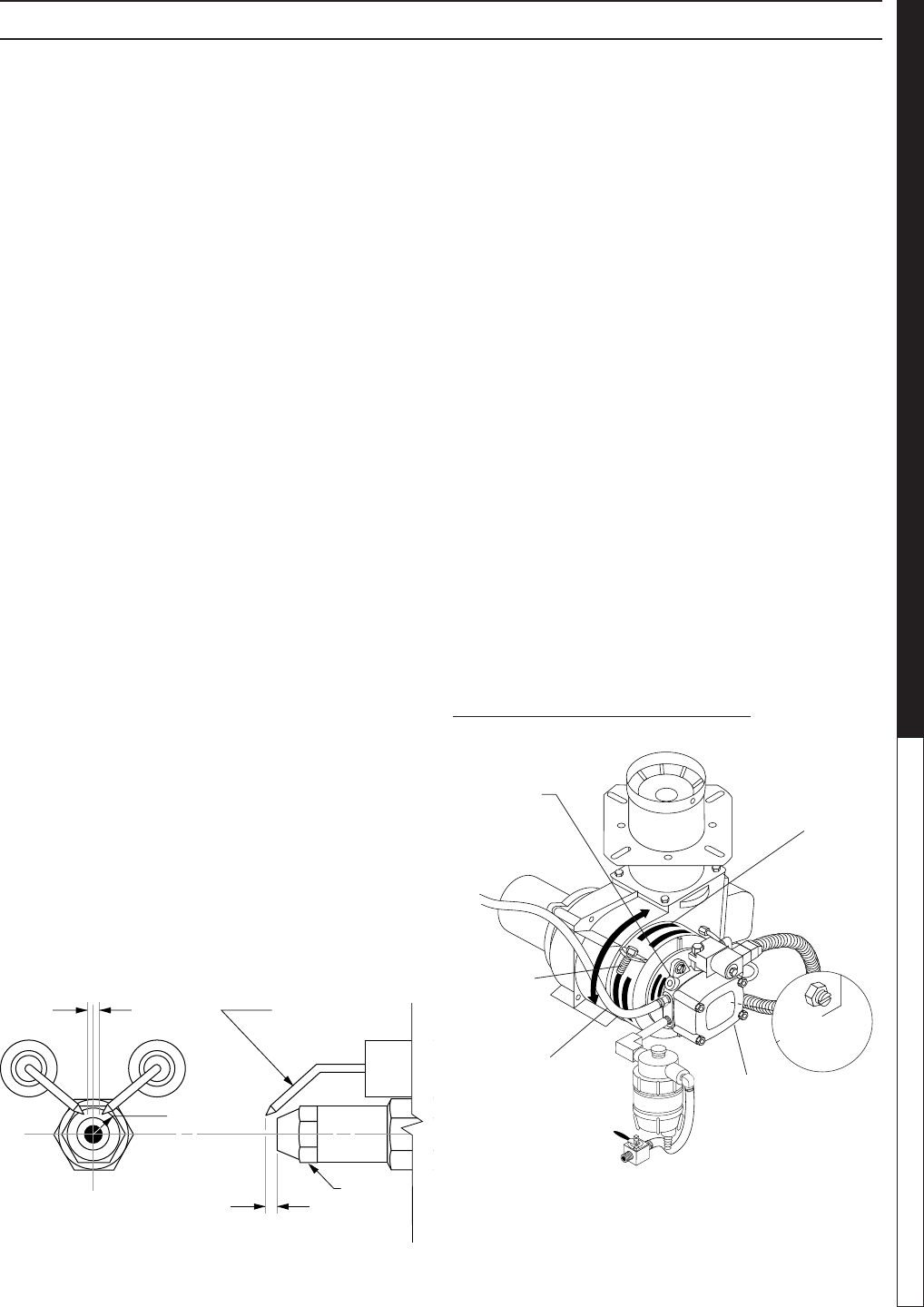
Electrode Setting:
(See illustration below.)
Burner Nozzle:
Keep the tip free of surface deposits by wiping it with a
clean, solvent-saturated cloth, being careful not to plug
or enlarge the nozzle. For maximum efciency, replace
the nozzle each season.
Air Adjustment:
Machines are preset and performance tested at the
factory - elevation 100 feet. A one-time initial correction
for your location will pay off in economy, performance
and extended service life. If a smoking or eye-burning
exhaust is being emitted from the stack, two things
should be checked. First, check the fuel to be certain
that kerosene or No. 1 home heating fuel is being used.
Next, check the air adjustment on the burner.
To adjust: Start machine and turn burner ON. Loosen
two locking screws found in the air shutter openings
(refer to illustration below) and close air shutter until
black smoke appears from burner exhaust vent. Note
air band position. Next, slowly open the air shutter until
white smoke just starts to appear. Turn air shutter half-
way back to the black smoke position previously noted.
Tighten locking screws.
If the desired position cannot be obtained using only
the air shutter, lock the air shutter in as close a position
as can be obtained, then repeat the above procedure
on the air band setting.
Periodically check wiring connections. If necessary to
adjust electrodes, use diagram.
Top View
Side View
5/32"
1/4"
5/32"
Nozzle
Electrode
FUEL AIR ADJUSTMENT
Pressure
Gauge
Port
Pressure
Adjustment
Screw
7-00098 Fuel
Pump
To Fuel
Tank
Air Band
Air Band
Adjustment
Screw
Return Line
MAINTENANCE

97-6132, 97-6151 • REV. 11/04
OPERATOR’S MANUAL PRESSURE WASHER
14
97-6132, 97-6151 • REV. 11/04
15
PRESSURE WASHER Troubleshooting Guide
Fuel Pressure Adjustment:
To adjust fuel pressure, turn the adjusting screw clock-
wise to increase, counterclockwise to decrease. Do not
exceed 200 psi. NOTE: When changing the fuel pump,
a bypass plug must be installed in the return port or the
fuel pump will not prime.
Removal of Soot and Heating Coil:
In the heating process, fuel residue in the form of soot
deposits may develop on the heating coil and block air
ow which will affect burner combustion. When soot
has been detected on visual observation, the soot
on the coil must be washed off after following the coil
removal steps.
1. Remove the tank head assembly by lifting the tank
head off.
2. Remove the two pipe nipples and associated t-
tings.
3. Lift the coil out of the outer wrap.
CAUTION: The coil weighs about 80 lbs. Use proper
lifting techniques.
4. Clean, repair and replace the coil by reversing the
above steps.
Coil Reinstallation:
Reinstall by reversing the above steps 4 through 1.
Final Note:
The 12 VDC burner systems can draw as much as 18
amps! For such burners to run properly, the battery and
engine charging system must be kept in good condition.
The engine must run at the correct RPM to adequately
charge the battery. It is equally important not to throttle
down the engine on models without batteries, since all
power to run the burner comes solely from the engine.
Do not throttle down the engine at anytime while the
machine is operating.
MAINTENANCE
97-6132, 97-6151 • REV. 11/04
OPERATOR’S MANUAL PRESSURE WASHER
14
97-6132, 97-6151 • REV. 11/04
15
PRESSURE WASHER Troubleshooting Guide
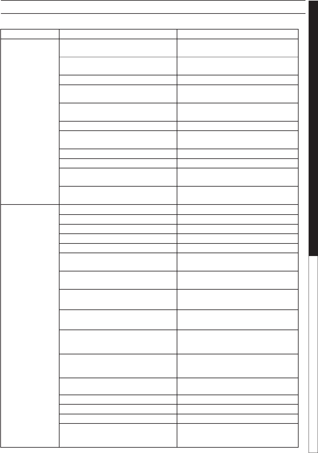
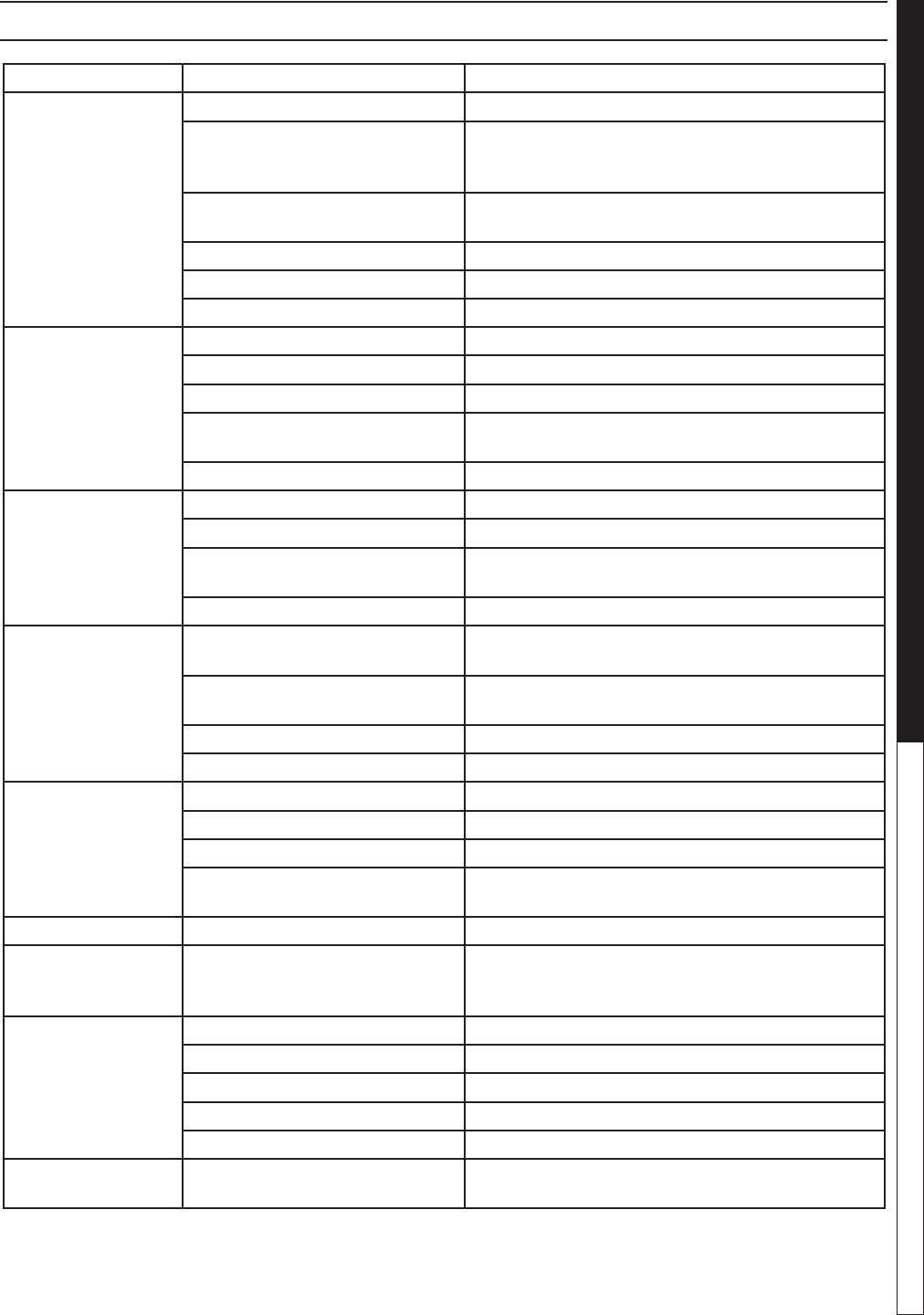
TROUBLESHOOTING
PROBLEM POSSIBLE CAUSE SOLUTION
LOW OPERATING
PRESSURE
Water supply is insufcient Use larger supply hose; clean lter at water
inlet.
Spray nozzle is old, worn or incorrect Match the nozzle number to the machine
and/or replace with new nozzle.
Belt slips Tighten or replace belt; use correct belt.
Plumbing or hose is leaking Check plumbing system for leaks. Retape
leaks with teon tape.
Unloader is faulty or misadjusted Adjust unloader for proper pressure. Install
repair kit when necessary or replace.
Packing in pump is worn Install new packing kit.
Discharge valve in pump or inlet is fouled
or dirty
Check inlet and discharge valve.
Discharge valve or inlet is worn Replace with valve kit.
Spray nozzle has obstruction Remove obstruction.
Steam pressure control valve is leaking
(where applicable)
Rebuild or replace as necessary.
Engine RPM is slow Set engine speed at proper specications /
see serial plate.
BURNER WILL
NOT LIGHT
There is little or no fuel Fill tank with fuel.
Improper fuel or water in fuel Drain fuel tank and ll with proper fuel.
Fuel line is clogged Clean or replace fuel line.
Fuel lter is plugged Replace fuel lter as needed.
Burner air bands are misadjusted Readjust air bands for clean burn.
Little or no fuel pressure from fuel pump Increase fuel pressure to specication and/
or replace fuel pump.
Burner transformer is faulty Test transformer for proper arc between
contacts. Replace as needed.
Electrical wiring is disconnected or has
short in it
All wire contacts should be clean and tight
with no breaks in wire.
Flex coupling is slipping on fuel pump
shaft or burner motor shaft
Replace if needed.
ON-OFF switch is defective Check for electrical current reaching burner
assembly with burner switch on. Replace
switce if needed.
Heavy sooting on coil and burner can
cause interruption of air ow and shorting
of electrodes
Clean as required.
Electrode setting is improper Check and reset according to diagram in
manual.
25 amp circuit breaker tripped Push in reset button.
Bridge rectier defective Test and replace.
12V DC relay defective Test and replace.
Fuel is not reaching combustion chamber Check fuel pump for proper ow. Check so-
lenoid ow switch on machines with spray
gun control for proper on-off ow control.
97-6132, 97-6151 • REV. 11/04
PRESSURE WASHER Troubleshooting Guide
16
97-6132, 97-6151 • REV. 11/04
17
PRESSURE WASHER Troubleshooting Guide
TROUBLESHOOTING
PROBLEM POSSIBLE CAUSE SOLUTION
BURNER WILL NOT
LIGHT (continued
from previous page)
Burner nozzle is clogged Clean as required.
Thermostat has malfunctioned Test and replace if needed.
Fuel solenoid has malfunctioned Test and replace if needed.
MACHINE SMOKES Fuel is improper or water is in fuel Drain tank and replace contaminated fuel.
Air adjustment is improper Readjust air bands on burner assembly.
Fuel pressure is low Adjust fuel pump pressure to specications.
Burner nozzle is plugged or dirty Replace nozzle. Check parts breakdown for
nozzle size.
Burner nozzle spray pattern is faulty Replace nozzle. Check parts breakdown for
nozzle size.
Coil and burner assembly have heavy
accumulation of soot
Remove coils and burner assembly, clean
thoroughly. Call local dealer.
Electrode setting is misaligned Realign electrodes to specications.
Smoke stack has obstruction Check for blockage or other foreign objects.
Engine RPM is low Increase RPM to correct specs. See serial
plate.
LOW WATER
TEMPERATURE
Fuel is improper or has water in it Replace with clean and proper fuel.
Fuel pressure is low Increase fuel pressure.
Fuel pump is weak Check fuel pump pressure. Replace pump if
needed.
Fuel lter is partially clogged Replace as needed.
Soot buildup on coils is not allowing
heat transfer
Clean coils.
Burner nozzle is improper Call your local dealer for proper nozzle.
WATER
TEMPERATURE
TOO HOT
Incoming water to machine is warm
or hot
Lower incoming water temperature.
Fuel pump pressure is too high Call your local dealer for proper fuel pres-
sure.
Fuel pump is defective Replace fuel pump.
Fuel nozzle is incorrect size See parts breakdown or serial plate for
proper size.
Water supplied is insufcient Check water GPM to machine.
Water ow is restricted Check nozzle for obstruction and proper
size. Check serial plate for correct size.
PRESENCE OF
WATER IN OIL
Oil seal is worn Check and replace if necessary.
Air humidity is high Check and change oil twice as often.
Packing is worn or bad Check and replace if necessary.
97-6132, 97-6151 • REV. 11/04
PRESSURE WASHER Troubleshooting Guide
16
97-6132, 97-6151 • REV. 11/04
17
PRESSURE WASHER Troubleshooting Guide
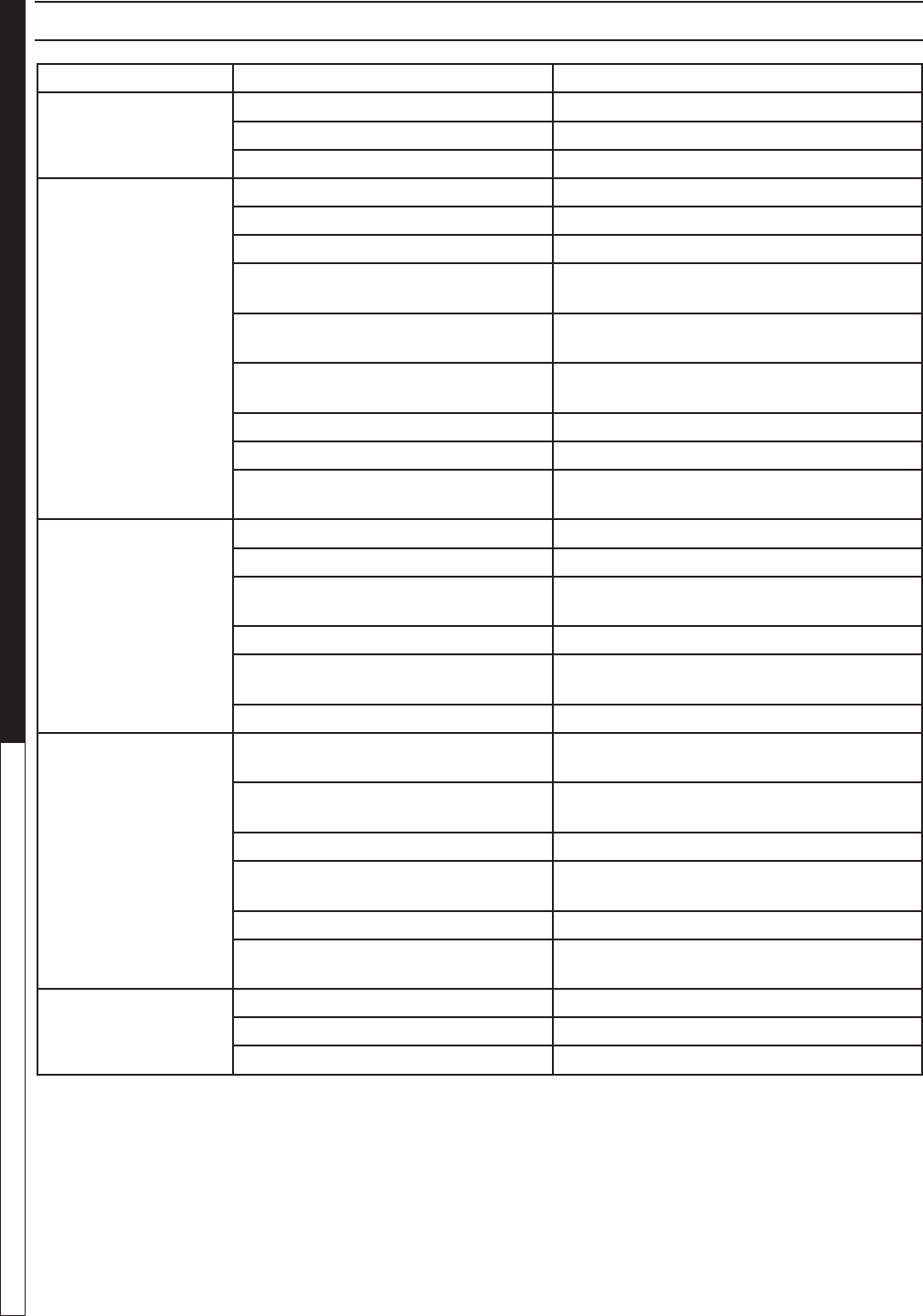
TROUBLESHOOTING
PROBLEM POSSIBLE CAUSE SOLUTION
DETERGENT NOT
DRAWING
Air is leaking Tighten all clamps. Check detergent lines for holes.
Injector head may be blocked,
dirty or damaged
Clean and make sure ball and spring behind
detergent hose barb or injector body are working
properly.
Filter screen on detergent suction
hose is plugged
Clean or replace.
Detergent has high viscosity Dilute detergent to specications.
Not using soap nozzle Insert soap nozzle into wand coupler.
Detergent level is low Add detergent if needed.
PUMP RUNNING
NORMALLY BUT
PRESSURE LOW
ON INSTALLATION
Pump is sucking air Check water supply and possibility of air seepage.
Valves are sticking Check and clean or replace if necessary.
Unloader valve seat is faulty Check and replace if necessary.
Nozzle sized incorrectly Check and replace if necessary (see serial plate for
proper size).
Packing piston is worn Check and replace if necessary.
FLUCTUATING
PRESSURE
Valves are worn Check and replace if necessary.
Valve has a blockage Check and replace if necessary.
Pump is sucking air Check water supply and air seepage at joint in suc-
tion line.
Packing piston is worn Check and replace if necessary.
PUMP NOISY Air is in suction line Check water supply and connections on suction
line.
Inlet or discharge valve springs
are weak or broken
Check and replace if necessary.
Excessive matter is in valves Check and replace if necessary.
Bearings are worn Check and replace if necessary.
WATER DRIPPING
FROM UNDER
PUMP
Piston packing is worn Check and replace if necessary.
O-Ring plunger retainer is worn Check and replace if necessary.
Piston is cracked Check and replace if necessary.
Pump protector is worn Lower water supply pressure. Do not run the spray
gun closed longer than 5 minutes.
OIL DRIPPING Oil seal is worn Check and replace if necessary.
EXCESSIVE
VIBRATION IN
DELIVERY LINE
Valves are functioning irregularly Check and replace if necessary.
BURNER MOTOR
WILL NOT RUN
Fuel pump has seized Replace fuel pump.
Burner fan loose or misaligned Position correctly and tighten set screw.
There is a loose wire Check and replace or tighten wiring.
Control switch is defective Replace switch.
Burner motor is defective Replace motor.
RELIF VALVE
LEAKS WATER
Relief valve is defective Replace or repair relief valve.
97-6132, 97-6151 • REV. 11/04
PRESSURE WASHER Troubleshooting Guide
18
97-6132, 97-6151 • REV. 11/04
19
PRESSURE WASHER OPERATOR’S MANUAL
PREVENTATIVE MAINTENANCE
This pressure washer was produced with the best available materials and quality craftsmanship. However, you
as the owner have certain responsibilities for the correct care of the equipment. Attention to regular preventative
maintenance procedures will assist in preserving the performance of your equipment. Contact your dealer for
maintenance. Regular preventative maintenance will add many hours to the life of your pressure washer. Perform
maintenance more often under severe conditions.
OIL CHANGE RECORD
MAINTENANCE CHARTS
MAINTENANCE SCHEDULE
Engine Oil Inspect Daily
Change Every 25 hours
Filter Every 50 hours
Air Cleaner Inspect Every 50 hours or monthly
Clean Every 3 months
Battery Level Check monthly
Engine Fuel Filter 500 hours or 6 months
Spark Plug Maintenance 500 hours or 6 months
Clean Fuel Tank(s) Annually
Replace Fuel Lines Annually
Pump Oil Inspect Oil level daily
Change Aftr rst 50 hours, then every 500 hours or annually
Clean Burner Filter Monthly (More often if fuel quality is poor)
Remove Burner Soot Annually
Burner Adjustment/Cleaning Annually
Replace Burner Nozzle Annually
Descale Coil Annually (more often if required)
Replace High Pressure Hose Every 6 months
Replace Quick Couplers Annually
Date Oil Changed
Month/Day/Year
Estimated Operating
Hours Since Last
Oil Change
Date Oil Changed
Month/Day/Year
Estimated Operating
Hours Since Last
Oil Change
97-6132, 97-6151 • REV. 11/04
PRESSURE WASHER Troubleshooting Guide
18
97-6132, 97-6151 • REV. 11/04
19
PRESSURE WASHER OPERATOR’S MANUAL
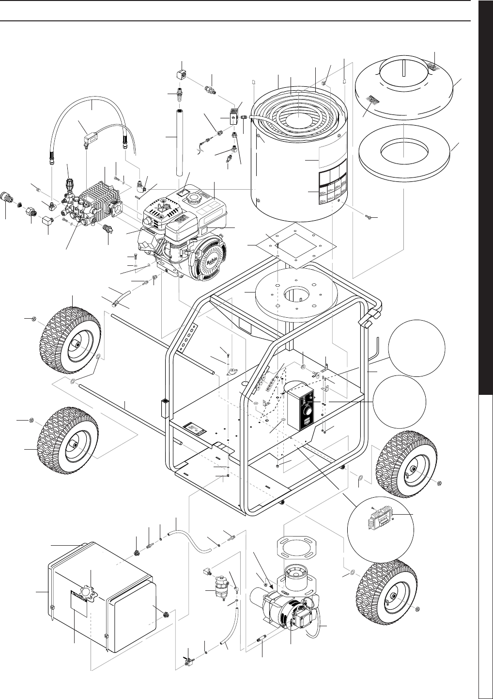
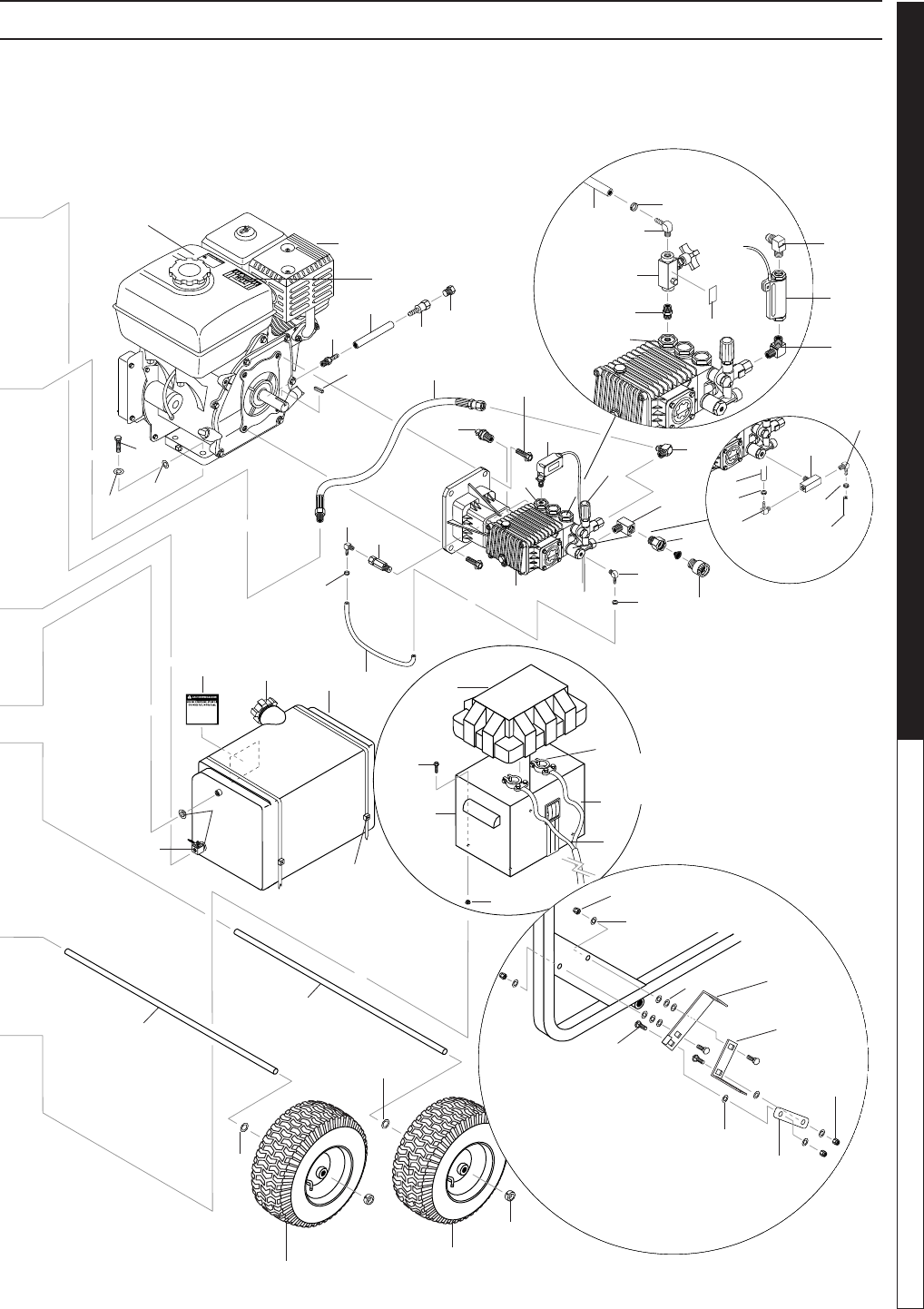
EXPLODED VIEW - 3020, 3025 MODELS
1
8
10
9
65
7
3
59
21
96
11
12
13
14
22
29
58
28 2
25
4
64
65
113
91
92
63
18
19
20
For
Detail See
Control
Box Illus.
18
19
34
56
77
35
98
23
27
99
26
47
103
17
14
76
60
73
38
15
57
16
50
51,105,106
20
20
90
86
88
84
31
87
108 31
108
100
107
31
45
31
54
53
46
54
52 39
24
Reversed
View of
Regulator
110
48
109
2
62
72
89
112
71
43
For Brake
Detail See
Reversed
View A-A
(Enlarged)
Pg.12
70
61
102
41
54
2
117
118
116
119
97-6132, 97-6151 • REV. 11/04
OPERATOR’S MANUAL PRESSURE WASHER
20
97-6132, 97-6151 • REV. 11/04
21
PRESSURE WASHER OPERATOR’S MANUAL
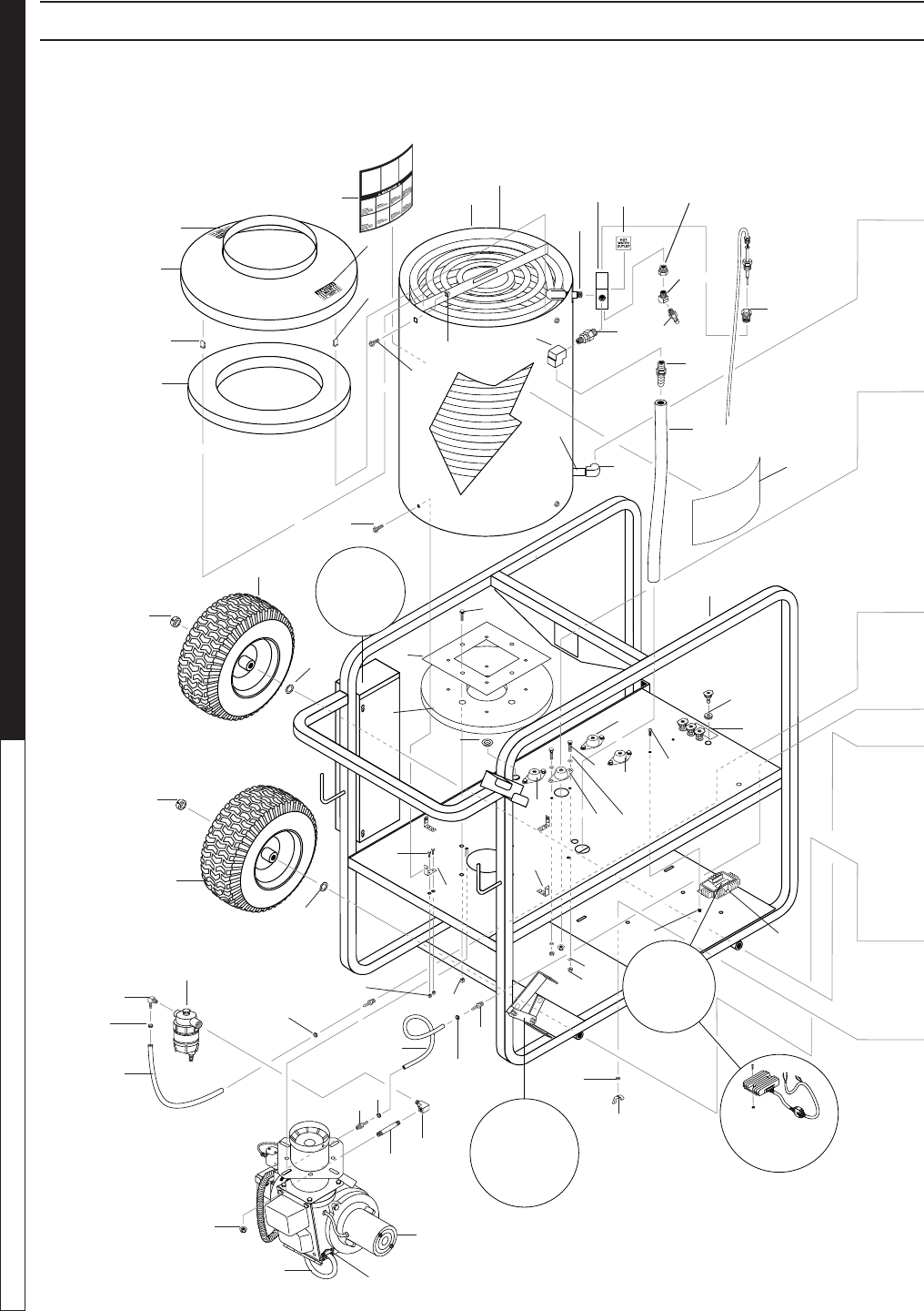
EXPLODED VIEW - 3030, 3530, 3530E, 4030E MODELS
3
17
12
13
48
94
4
19
18
59
5
6
2
1
11
910
7
8
20
18
19
20
57
39
38
36
37
37
For
Detail See
Control
Box Illus.
15
52
16
Reversed
View of
Component
51
50
54
42
84
31
101
31
53
60
76 62
14
78
73
41
43
Honda Electric
Start Only
72
89 90
54
14
87
38
36
86
45
100
31
107
31
88
2
61
3
93
For Brake
Detail See
View A-A
(Enlarged)
105
106
118
116
117
97-6132, 97-6151 • REV. 11/04
OPERATOR’S MANUAL PRESSURE WASHER
20
97-6132, 97-6151 • REV. 11/04
21
PRESSURE WASHER OPERATOR’S MANUAL
EXPLODED VIEW - 3030, 3530, 3530E, 4030E MODELS
34
26
29
28
44
31
27
25
47
21
2
91
95
49
30
31
24
23
22
33
55
35
18
46
20
19
18
20
46
33
56
58
69
67
66
68
77
70
Electric Start
Model Only
65
64
71
113
63
32 97
82
80
79
Steam
Option
115
31
32
32
31
115
83
96
92
58
31
110
108
Steam
Option
View A-A
(Enlarged)
74
85
75
81
104
40
114
111
9
54
81
81
74

97-6132, 97-6151 • REV. 11/04
OPERATOR’S MANUAL PRESSURE WASHER
22
97-6132, 97-6151 • REV. 11/04
23
PRESSURE WASHER OPERATOR’S MANUAL
EXPLODED VIEWS PARTS LIST
ITEM PART NO. DESCRIPTION QTY
1 95-07290029 Tank Head Assembly,
16" Dia. x 8" Stack 1
2 10-02025A Label, Hot/Caliente w/Arrows
Warning 3
3 90-50045 Clip, Retaining, U-Type 4
4 95-07290053 Retainer, Burner Insulation 1
5 95-07121218 Coil, Dura, 14.5" Dia, Sch 80
(3030, 3530, 3530E, 4035E) 1
95-07102310 Coil Assy (3020, 3025) 1
6 95-07200129 Wrap, Outer Coil
(3030, 3530, 3530E, 4035E) 1
95-07102249 Wrap, Outer Coil (3020, 3025) 1
7 2-0008 Nipple, 1/2" x M x M, Hex
(3020, 3025) 1
2-000891 Nipple 2-1/2" x 1/2", Pipe
(3030, 3530, 3530E, 4035E) 1
8 95-07101226 Block, Discharge, 1/2" x 1/2",
Brass 1
9 2-00270 Elbow, 3/8" Male Pipe (Legacy),
(Steam Option) 1
10 2-2007 Nipple, 3/8" x 3/8" NPT ST Male1
11 2-3409 Disk, Rupture Assy, 7000 PSI 1
12 2-1108 Hose Barb, 1/2” Barb x 3/8” MPT,
Push-On 1
13 4-02110000 Hose, 1/2" Push-On, Conduit
(3030,3530,3530E,4035E) 2.5 ft.
(3020,3025) 2 ft.
14 90-19710 Screw, 1/4" x 3/4" HH NC (3030,
3530,3530E,4035E) 9
(3020,3025) 8
15 7-01482 Insulation, Tank Bottom,
1" Blanket 1
16 95-07102227 Assy, Frame
(3030, 3530, 3530E, 4035E) 1
95-07104955 Assy. Frame, Mini (3020, 3025)1
17 11-013 Label, Die-Cut 2
11-014 Label, Die-Cut 2
18 4-0307 Wheel & Tire, 6" Steel Rim 4
19 90-20041 Collar, 5/8" Bore Shaft 4
20 90-4005 Washer, 5/8", Flat, SAE 4
21 5-0003 Engine, Robin, 6 HP, 200W
(3020) 1
5-0004 Engine, Robin, 7 HP, 200W
(3025) 1
5-01021 Engine, Honda, GX270QAR2,
9 HP, 18 AMP (3030) 1
5-01072 Engine, Honda, GX340QNR2,
11 HP E/S, 18 AMP (3530E) 1
5-01070 Engine, Honda, GX340QAH2,
11 HP, 18 AMP (3530) 1
5-010720 Engine, Honda, GX390KQNR2,
13 HP E/S, 18 Amp (4035E) 1
ITEM PART NO. DESCRIPTION QTY
22 5-1630 Pump, Legacy, WMG-2625
(302017) 1
5-1631 Pump, Legacy, WMG-2530
(302517) 1
5-23125 Pump, General, TX-1506G8
(303031) 1
5-23122 Pump, General, TX1509G8
(353031, 353031E) 1
5-23161 Pump, General, EZ-4035
(403531E) 1
5-1960 Pump Legacy, GS3040G
(303037) 1
5-1961 Pump, Legacy, GS3540G
(353037, 353037E) 1
5-1962 Pump, Legacy GS4040G
(403537E) 1
23 4-02047725 Hose, 3/8" x 25", 2 Wire,
Pressure Loop 1
24 2-30082 Pump Protector, 1/2" PTP 1
25 6-021720 Switch, Pressure N/O, 1/4" NPT
SS (Except Steam Option) 1
26 2-0053 Elbow, 1/2" JIC, 3/8", 90°
(303031, 303037 353031,
353037, 353031E, 353037E,
403531E, 403537E) 1
2-00601 Elbow, 1/2" JIC x 3/8" FEM, 90°
(302017, 302517) 1
27 5-3025 Unloader, PA 8 GPM @3650
PSI, VB75K47L (303031,
353031, 353031E, 403531E) 1
5-3151 Unloader, APR.S 3000,
5.3 @3000 (302017, 302517) 1
5-3029 Unloader, PA 8 @ 3650
(303037, 353037, 353037E,
403537E) 1
28 2-1024 Elbow, 1/2" Street, Brass 1
29 2-10942 Swivel, 1/2" MP x 3/4" GHF
w/Strainer 1
30 2-1088 Hose Barb, 1/4" Barb x 1/8" ML
Pipe, 90° (3030, 3530,
3530E, 4035E) 1
31 2-9040 Clamp, Hose, UNI .46 - .54
(3030, 3530, 3530E, 4035E) 6
(3020, 3025) 4
32 4-02100000 Hose, 1/4", Push-On, Fuel Line,
14 inches (Steam Option) 1
33 2-0115 Box, Battery, M-100
(3530E, 4035E) 1
2-011500 Plate, Battery Box, Large,
PolyPro (3530E, 4035E) 1
34 2-0115090 Tank, Fuel, 6 Gallon 1
35 2-01167
Cap, Fuel Tank, Plastic H60-AV
1

97-6132, 97-6151 • REV. 11/04
OPERATOR’S MANUAL PRESSURE WASHER
22
97-6132, 97-6151 • REV. 11/04
23
PRESSURE WASHER OPERATOR’S MANUAL
EXPLODED VIEWS PARTS LIST
ITEM PART NO. DESCRIPTION QTY
36 2-01053 Mount, Rubber Vibration, 40
Duro (Blue Dot) 2
37 2-01052 Mount, Rubber Vibration,
30 Duro 2
38 95-07290007 Tab, Outer Wrap 4
39 2-0103 Grommet, Rubber,
Nozzle Holder 4
40 90-100472 Bolt, Carriage, 1/4" x 1" 4
41 Burner Assy, See Burner Spec's Page 31
42 90-2025 Nut, 5/16" Wing
(3530E, 4035E) 4
43 90-20040 Nut, 3/8" Flange, Whiz Loc 4
44 2-1089 Hose Barb, 1/4" Barb x 1/4" Pipe,
90° (303037, 353037, 353037E,
403537E) 1
2-1088 Hose Barb, 1/4" Barb x 1/8" ML
Pipe, 90° (303031, 353031,
353031E, 405351E) 1
45 2-1085 Hose Barb, 1/4" Barb x 1/4" ML
Pipe 1
46 95-07102229 Axle, 30" (3030, 3530, 3530E,
4035E) 2
95-07104723 Axle, 27.80" (3020, 3025) 2
47 10-02029 Label, Danger Cool Engine 1
48 2-00602 Elbow, 1/2" JIC x 1/2" Fem, 90°
(3030, 3530, 3530E, 4035E) 1
2-0053 Elbow, 1/2" JICM x 3/8", 90°
(3020, 3025) 1
49 2-3100544 Valve, E-Z Start, 3/8" MPT x 1/8"
FPT (3030, 3530, 3530E,
4035E) 1
50 90-2020 Nut, Cage, 3/8" x 12 Gauge 4
51 6-0615 Regulator, Voltage, 15 V
(Pull Start) 1
77-31620-ZG5-003
Regulator/Rectier, 18 AMP
(Electric Start) 1
52 90-1006 Bolt, 5/16" x 3/4" NC 8
53 90-2001 Nut, 5/16" ESNA 8
54 90-4001 Washer, 5/16" Flat 20
55 90-19715 Screw, 5/16" x 1-1/4", Whiz Loc
(3530E, 4035E) 4
56 2-30057 Valve, 1/4" Shut OFF 1
57 11-3218 Label, Nozzle Identication 1
58 1-190031 Cap, Valve w/1/4" Gauge Port
(303031, 353031, 353031E,
403531E) 1
15-070042532 Cap, Valve w/1/4" Gauge Port,
Legacy (302017, 302517) 1
70-460146 Cap, Valve w/1/4” Gauge Port
(303037, 353037, 353037E,
403537E) 1
ITEM PART NO. DESCRIPTION QTY
59 7-014832 Insulation, Tank Head 1
60 90-19960 Screw, 3/8" x 1-1/4", Whiz Loc 4
61 90-2022 Nut, Cage, 1/4" x 16 Gauge 5
62 10-09004 Label, Hot Water Outlet 1
63 2-11063
Plug, Push-On, Oil Drain,
Honda
1
64 2-11062 Swivel, 1/4" JIC FEM, Push-On1
65 2-10491 Plug, 1/4" JIC 1
66 6-0117 Wire, THWN, 6 Gauge, Red
(3530E, 4035E) 2.75 ft.
67 6-0118 Wire, THWN, 6 Gauge, Black
(3530E, 4035E) 3.75 ft.
68 6-05101 Connector, Battery Post,
Universal (3530E, 4035E) 2
69 90-20012 Nut, 5/16" Flange, Whiz Loc
(3530E, 4035E) 4
70 2-30062 Valve, Anti-Siphon, Watts 8B 1
71 95-07141121 Key, 0.247 SQR x 2.125
(3030,3530,3530E,4035E) 1
95-07141120 Key, 0.185 SQR x 1.75"
(3020, 3025) 1
72 90-20231 Nut, Cage, 1/4" x 12 Gauge 8
73 90-19711 Screw, 1/4" x 1/2" HH NC,
Whiz Loc 8
74 90-2000 Nut, 1/4"-20, ESNA 4
75 95-07104828 Bracket, Brake Pad 1
76 10-03015 Label, Warning, Text 1
77 10-020110 Label, Use Only Kerosene 1
78 2-01404 Bushing, 7/8" Snap
(3030, 3530, 3530E, 4035E) 1
79 10-99011 Label, Open For Steam
(Steam Option) 1
80 2-0004 Nipple, 1/4", Hex, Steel
(Steam Option) 1
81 90-4000 Washer, 1/4", Flat, SAE 12
82 2-30151 Valve, Flow Control w/Metering
(Steam Option) 1
83 2-1037 Tee, 1/4" Branch Male,
Legacy Pumps (Steam Option)1
84 2-001346 Nipple, 1/4" x 2", Galvanized 1
85 95-07104829 Linkage, Brake 1
86 2-99050 Filter, Parker Fuel/Oil/H2O
(10 Micron), Generic 1
87 4-02100000 Fuel Line, 1/4" 9 in
88 4-02100000 Fuel Line, 1/4"(3030, 3530,
3530E, 4035E) 6 in
(3020, 3025) 11 in
89 6-01041 Service Cord, 12/3 Jr. (3030,
3530, 3530E, 4035E) 3.33ft
(3020, 3025) 2.66 ft

97-6132, 97-6151 • REV. 11/04
OPERATOR’S MANUAL PRESSURE WASHER
24
97-6132, 97-6151 • REV. 11/04
25
PRESSURE WASHER OPERATOR’S MANUAL
ITEM PART NO. DESCRIPTION QTY
90 6-0516 Strain Relief, 1/2" 1
91 90-1009 Bolt, 5/16" x 1-1/2" 4
92 90-4008 Lock Washer, 5/16" 4
93 90-4008 Lock Washer, 5/16"
(3530E, 4035E) 4
94 2-000891 Nipple, Galv, 1/2" x 2-1/2"
(3030, 3530, 3530E, 4035E) 1
95 4-02100000 Hose, 1/4 x 14" 1
96 90-10053 Bolt, 5/16" - 24 x 3/4" NF (3020,
3025) 4
90-19960 Screw, 3/8" x 1-1/4" Whiz Loc
(3030, 3530, 3530E, 4035E) 4
97 2-1089 Elbow, 1/4" Hose Barb x 1/4"
Pipe, Steam Option
(3030, 3530, 3530E, 4030E) 1
98 2-10818 Reducer, M14 x 1/4" F
(3020, 3025) 1
99 2-1046 Plug, 1/4", Countersunk
(3020, 3025) 1
100 2-1089 Hose Barb, 1/4" Barb x 1/4" Pipe,
90° 1
101 2-1022 Elbow, 1/4" Street 1
102 2-01403 Bushing, 5/8" Snap (3020,
3025) 1
103 7-01487 Insulation, Blanket, 18" x 52",
Fiberglass (3020, 3025) 1
104 95-07104827 Lever, Brake 1
EXPLODED VIEWS PARTS LIST
ITEM PART NO. DESCRIPTION QTY
105 90-1999 Screw, 10/32" x 3/4" BH SOC CS
(3020, 3025, 3030, 3530) 3
90-1994 Screw, 10/32" x 1-1/4" RH SL
(3530E, 4035E) 2
106 90-017 Nut, 10/32" Kep (3530E,
4035E) 2
(3020, 3025, 3030, 3530) 3
107 2-10866 Hose Barb, 1/4" Barb x 3/8",
Double 1
108 2-010061 Bushing, Rubber Nitrile 2
109 90-4008 Washer, 5/16" Lock Split Ring
(3020, 3025) 4
110 6-05134 Cable, Tie, 48" 2
111 6-021730 Switch, Flow (Steam Option) 1
112 2-01411 Bushing, 3/4" Snap (3020,
3025) 1
113 4-02100000 Hose, 1/4" Push-On (3020,
3025) 7"
(3030, 3530, 3530E, 4035E) 11"
114 2-0053 Elbow, 1/2" JIC x 3/8", 90°
(Steam Option) 1
115 2-1089 Elbow, 1/4" x 1/4" Pipe (Steam
Option, Legacy Pumps) 2
116 2-00742 Adapter, 1/2” x 1/2” Pipe STL 1
117 2-00681 Bushing, 1/2” x 3/8” STL 1
118 2-00575 Bushing, 3/8” STL, Street, 45° 1
119 10-0624 Label, RPM Factory Set 1
Not Shown
97-6132, 97-6151 • REV. 11/04
OPERATOR’S MANUAL PRESSURE WASHER
24
97-6132, 97-6151 • REV. 11/04
25
PRESSURE WASHER OPERATOR’S MANUAL
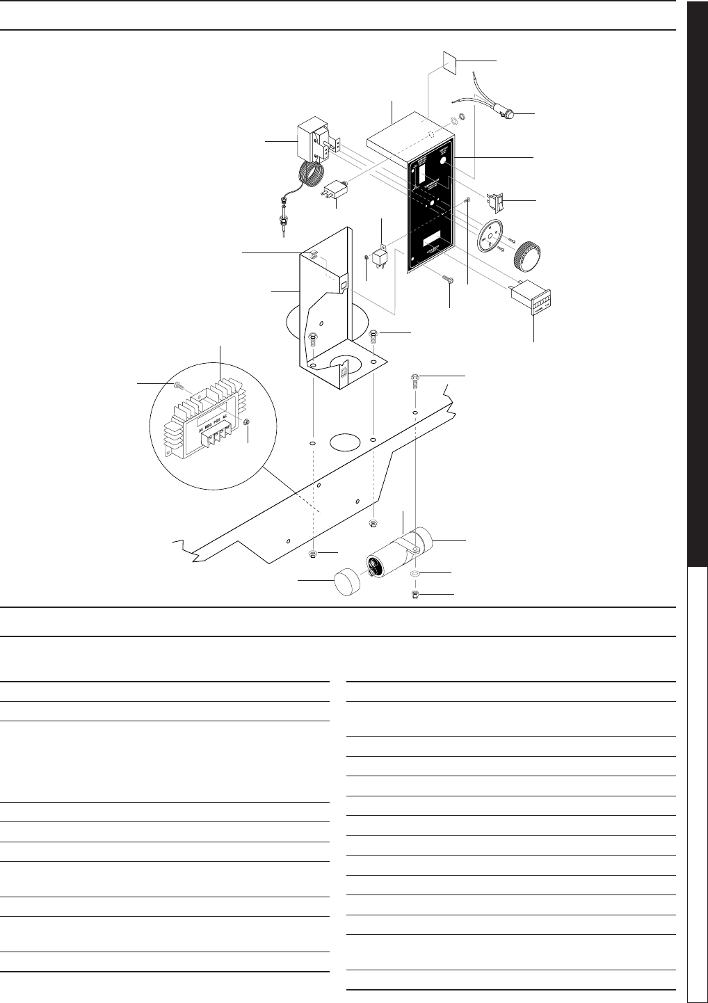
ITEM PART NO. DESCRIPTION QTY
1 6-06070 Capacitor 1
2 6-0615 Regulator, Voltage, 15 Volt 1
3 95-07390109 Box, Electrical 1
90-1994 Screw, 10/32" x 1-1/4"
(Ground) 1
90-017 Nut, 10/32", KEPS 4
11-1042 Ground Label 1
4 95-07104960 Assy, Cover, Elec. Box 1
5 4-05088 Thermostat, Adjustable, 302°F 1
6 6-020590 Light, Indicator, Green 12V 1
7 6-020251 Switch, Curvette RA901VB-B-1-
V, Carling 1
8 4-050823 Meter, Hobbs Hour 1
9 6-03671 Relay, P & B, VF4-41F11,
12VDC, 40AMP 1
10 6-041250 Breaker, 1658-G41-02-P10-25A 1
ITEM PART NO. DESCRIPTION QTY
11 90-19708 Screw, 1/4" x 1-1/4" Hex, Whiz 1
12 90-19711 Screw, 1/4" x 1/2" HH NC,
Whiz Loc 2
13 90-200012 Nut, 1/4" Whiz Loc 2
14 90-2000 Nut, 1/4", ESNA, NC 1
15 90-19942 Screw, 10/32" x 3/4" Hex 2
16 2-90159 Clampt, Hose 1
17 90-2018 Nut Cage, 10/32" x 16 GA 2
18 11-0357 Label, Control Panel 1
19 90-4000 Washer, 1/4" 1
20 90-017 Nut, 10/32" Keps 4
21 90-1999 Screw, 10/32" x 3/4" 3
22 90-1991 Screw, 10/32" x 1/2" 1
23 2-011681 Cap, Capacitor, 1.37 x 1.50 x
.060 Blk, w/o Hole 1
24 10-990247 Label, Reset 1
5
4
6
22
7
10 9
20
16
12
11
8
15
21
2
20
19
14
13
23
1
3
17
Reversed
View
18
CONTROL PANEL EXPLODED VIEW - 3020, 3025 MODELS
3020, 3025 CONTROL PANEL PARTS LIST
24
97-6132, 97-6151 • REV. 11/04
OPERATOR’S MANUAL PRESSURE WASHER
26
97-6132, 97-6151 • REV. 11/04
27
PRESSURE WASHER OPERATOR’S MANUAL
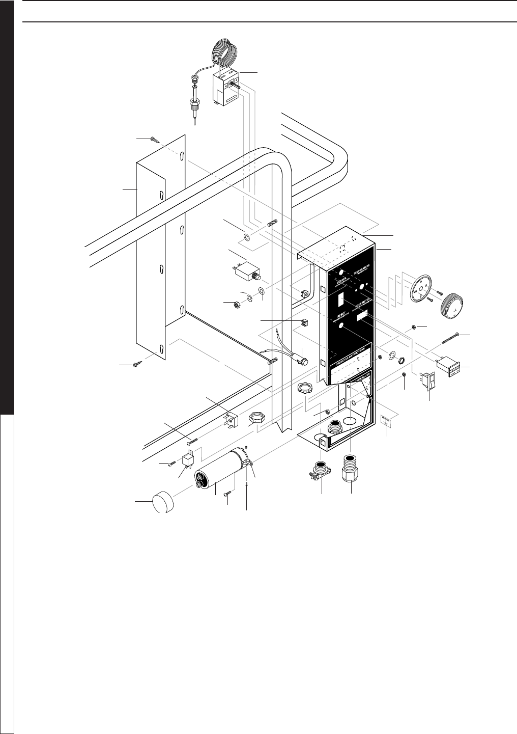
CONTROL PANEL - 3030, 3530, 3530E, 4035E MODELS
28
1, 23
2
6
14
4
5
28
12
11
9
10
8
13
19
22
15
16
3
17
20
18
21
7
25
24
27
26
19
25
29
30

97-6132, 97-6151 • REV. 11/04
OPERATOR’S MANUAL PRESSURE WASHER
26
97-6132, 97-6151 • REV. 11/04
27
PRESSURE WASHER OPERATOR’S MANUAL
3030, 3530, 3530E, 4035E CONTROL PANEL PARTS LIST
ITEM PART NO. DESCRIPTION QTY
1 4-05088 Thermostat, Adjustable, 302°F 1
2 95-07102228 Cover, Electric Box 1
3 90-1991 Screw, 10/32" x 1/2" BHSOC,
Black 1
4 6-041250 Breaker,
1658-G41-02-P10-25A 1
5 6-05181A Locknut, 1/2" 1
6 6-020590 Light, Indicator, Green 12V 1
7 90-2018 Cage, Nut, 10/32" x 16 GA 6
8 11-0505 Label, Control Panel 1
11-0507 Label, Control Panel 1
9 4-050823 Hour Meter, Hobbs, 12-48VDC 1
10 6-020251 Switch, Curvette RA901VB-B-
1-V, Carling 1
11 6-0516 Strain Relief, 1/2" Metal,
Two Screw 2
12 6-05152 Strain Relief, Small 1
13 95-07102231 Box, Electric, 16 GA MS 1
14 90-2006 Nut, 5/16" Hex 2
15 6-0611 Rectier, Bridge (3530E,
4035E) 1
ITEM PART NO. DESCRIPTION QTY
16 6-03671 Relay, P & B, VF4-41F11,
12VDC, 40AMP 1
17 6-06070 Capacitor (3030, 3530) 1
18 6-06071 Bracket, Capacitor (3030, 3530)1
19 90-017 Nut, 10/32" Keps 8
20 90-14 Screw, 6/32" x 3/8", RND HD
MCH (3030, 3530) 2
21 90-200430 Nut, 6/32" Keps (3030, 3530) 3
22 90-1999 Screw, 10/32" x 3/4" BH SOC CS
(3530E, 4035E) 1
23 6-02170 Conduit, Split, 1/4" 5.5 ft.
24 90-4008 Washer, 5/16", Lock, Split Ring 2
25 90-40011 Washer, 5/16", Flat, Cut 4
26 90-1994 Screw, 10/32" x 1-1/4"
(Ground) 1
27 11-1042 Label, Ground 1
28 90-19942 Screw, 10/32" x 3/4", HEX 6
29 2-011681 Cap, Capacitor, 1.37 x 1.5 x .06
Blk, w/o Hole 1
30 90-132 Screw, 6/32" x 5/8" (3030,3530)1
Not Shown
97-6132, 97-6151 • REV. 11/04
OPERATOR’S MANUAL PRESSURE WASHER
28
97-6132, 97-6151 • REV. 11/04
29
PRESSURE WASHER OPERATOR’S MANUAL
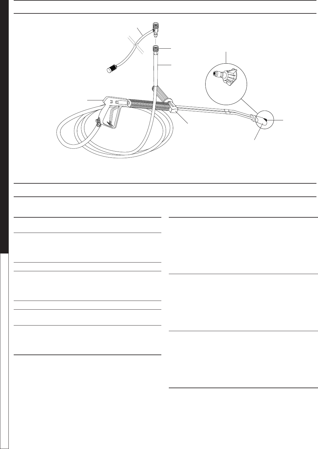
HOSE & SPRAY GUN ASSEMBLY
3
2
18
6
5
4
7
ITEM PART NO. DESCRIPTION QTY
1 2-2002 Coupler, 3/8" Female 1
2-0121 Quick Coupler O-Ring LG 1
2 4-02093450BC Hose, 3/8" x 50', 1 Wire, Blue
w/Coupler (All Except 4035) 1
4-02073450RC Hose Only, 3/8" x 50', 2 Wire,
Red w/Coupler (4035) 1
3 4-01246 Spray Gun, Shutoff, AP 1000 1
4 4-0111341A Wand, VP Zinc 1/4", W/Coupler,
W/Soap Nozzle 1
83-SSVPKIT Repair Kit, VP Wand, SS
Seat 1
5 4-06540 Nozzle, 1/8", Soap Only, Brass 1
6 2-2001 Coupler, 1/4" Male 1
2-0119 Quick Coupler O-Ring Sm 1
7 4-011184 Detergent Injector Assy #3
(3030, 3530, 3530E, 4035E) 1
4-011183 Detergent Injector Assy #2
(3020, 3025) 1
Pressure
Nozzle
HOSE & SPRAY GUN PARTS LIST
ITEM PART NO. DESCRIPTION QTY
8 4-12803515 Nozzle, SAQMEG 1503.5, Yellow
(3020, 3025, 4035) 1
4-12803525 Nozzle, SAQMEG 2503.5, Green
(3020, 3025, 4035) 1
4-12803540 Nozzle, SAQMEG 4003.5, White
(3020, 3025, 4035) 1
4-12803500 Nozzle, SAQMEG 0003.5, Red
(3020, 3025, 4035) 1
4-12804015 Nozzle, SAQMEG 1504, Yellow
(3530) 1
4-12804025 Nozzle, SAQMEG 2504, Green
(3530) 1
4-12804040 Nozzle, SAQMEG 4004, White
(3530) 1
4-12804000 Nozzle, SAQMEG 0004, Red
(3530) 1
4-12803015 Nozzle, SAQMEG 1503, Yellow
(3030) 1
4-12803025 Nozzle SAQMEG 2503, Green
(3030) 1
4-12803040 Nozzle SAQMEG 4003, White
(3030) 1
4-12803000 Nozzle SAQMEG 0003, Red
(3030) 1
Not Shown
97-6132, 97-6151 • REV. 11/04
OPERATOR’S MANUAL PRESSURE WASHER
28
97-6132, 97-6151 • REV. 11/04
29
PRESSURE WASHER OPERATOR’S MANUAL
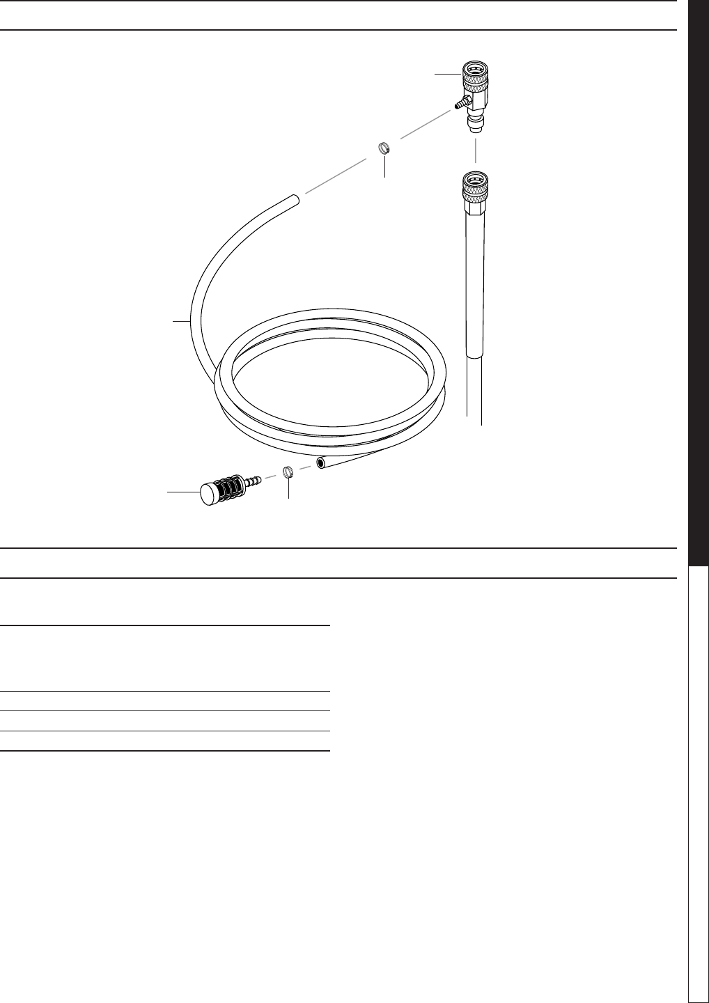
DOWNSTREAM INJECTOR ASSEMBLY
ITEM PART NO. DESCRIPTION QTY
1 3-12021 Injector, Detergent, Non-Adjust
#3, (4-011184) 1
3-1202 Injector, Detergent, Non-Adjust
#2, (4-011183) 1
2 2-9040 Clamp, Hose, UNI .46 - .54 2
3 4-02080000 Tube, 1/4" x 1/2", Clear Vinyl 6 ft.
4 2-1904 Strainer, 1/4", Hose Barb 1
4
3
1
2
2
DOWNSTREAM INJECTOR PARTS LIST
97-6132, 97-6151 • REV. 11/04
OPERATOR’S MANUAL PRESSURE WASHER
30
97-6132, 97-6151 • REV. 11/04
31
PRESSURE WASHER Specications
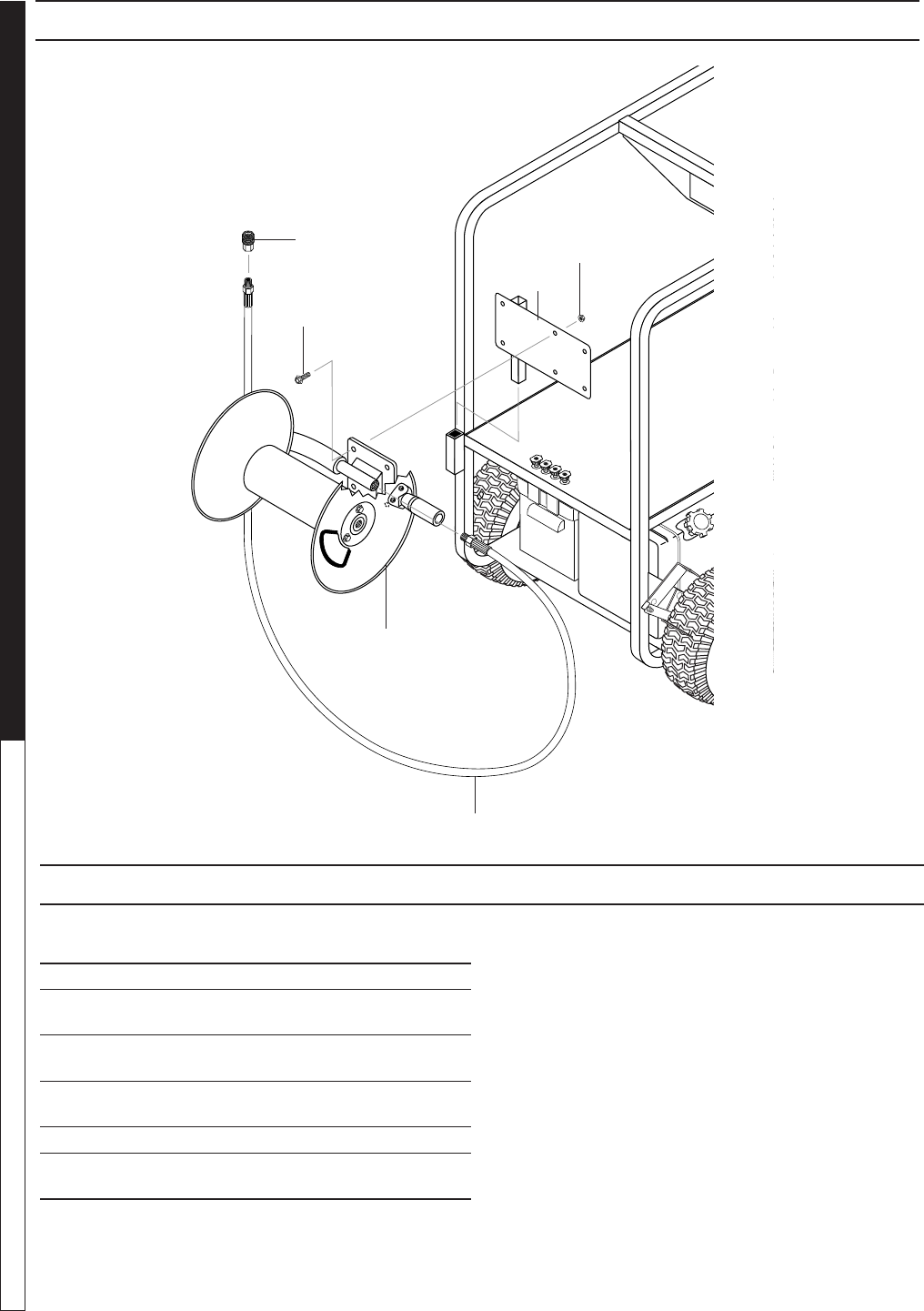
HOSE REEL OPTION
HOSE REEL PARTS LIST
ITEM PART NO. DESCRIPTION QTY
1 2-2002 Coupler, 3/8", Female, Brass 1
2 4-02047736 Hose, 3/8", 2 Wire Pressure
Loop 1
3 4-02755030 Hose Reel, 100' Non-Pivot
E-ZEE w/Pin Lock 1
4 90-1996 Screw, 3/" x 3/4" HH NC, Whiz
Loc 4
5 90-20040 Nut, 3/8" Flange, Whiz Loc, NC4
6 95-072900891 Bracket, E-ZEE Hose Reel Right,
Wrinkle Black 1
5
6
4
2
3
1

97-6132, 97-6151 • REV. 11/04
OPERATOR’S MANUAL PRESSURE WASHER
30
97-6132, 97-6151 • REV. 11/04
31
PRESSURE WASHER Specications
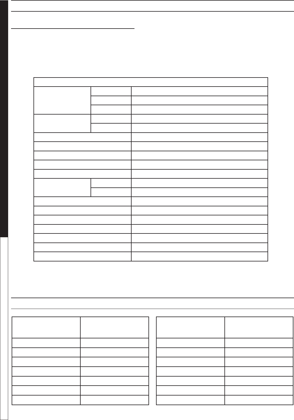
SPECIFICATIONS
BECKETT BURNER SPECIFICATIONS
Burner Burner Fuel Pump/ Fuel
Model # Assy # Fuel Nozzle Transformer Motor Solenoid/Cord Solenoid Coil Electrode
302017 7-00007 7-01260 7-515242 7-21699 7-00098 7-21754U 7-578727
302517 7-00007 7-01260 7-515242 7-21699 7-00098 7-21754U 7-578727
303031 7-00031 7-01215 7-515242 7-21699 7-00098 7-21754U 7-578727
303037 7-00031 7-01215 7-515242 7-21699 7-00098 7-21754U 7-578727
353031 7-00031 7-0101 7-515242 7-21699 7-00098 7-21754U 7-578727
353037 7-00031 7-0101 7-515242 7-21699 7-00098 7-21754U 7-578727
353031E 7-00031 7-0101 7-515242 7-21699 7-00098 7-21754U 7-578727
353037E 7-00031 7-0101 7-515242 7-21699 7-00098 7-21754U 7-578727
403531E 7-00031 7-0102 7-515242 7-21699 7-00098 7-21754U 7-578727
403537E 7-00031 7-0102 7-515242 7-21699 7-00098 7-21754U 7-578727

SGP SERIES PRESSURE WASHER
WARRANTY
SHARK LIMITED NEW PRODUCT WARRANTY
PRESSURE WASHERS
WHAT THIS WARRANTY COVERS
All SHARK PRESSURE WASHERS are warranted by SHARK to the original purchaser to be free from defects in materials
and workmanship under normal use, for the periods specied below. This Limited Warranty is subject to the exclusions shown
below, is calculated from the date of the original purchase, and applies to the original components only. Any parts replaced
under this warranty will assume the remainder of the part’s warranty period. This warranty applies to the original purchaser
and is not transferable.
LIMITED LIFETIME PARTS WARRANTY:
Components manufactured by SHARK, such as frames, handles, coil wraps, oat tanks, and belt guards. All heating coils
will have a three year warranty. Internal components on the oil-end of all pressure washer pumps will have a seven year war-
ranty.
ONE YEAR PARTS WARRANTY:
All other components, excluding normal wear items as described below, will be warranted for one year on parts. Warranty on
these parts will be for one year regardless of the duration of the original component manufacturer’s part warranty.
WARRANTY PROVIDED BY OTHER MANUFACTURERS:
Motors, generators, and engines, which are warranted by their respective manufacturers, are serviced through these manufac-
turers’ local authorized service centers. SHARK cannot provide warranty on these items.
WHAT THIS WARRANTY DOES NOT COVER
This warranty does not cover the following items:
1. Normal wear items, such as nozzles, guns, discharge hoses, wands, quick couplers, seals, lters, gaskets, O-rings,
packings, pistons, pump valve assemblies, strainers, belts, brushes, rupture disks, fuses, pump protectors.
2. Damage or malfunctions resulting from accidents, abuse, modications, alterations, incorrect installation, improper
servicing, failure to follow manufacturer’s maintenance instructions, or use of the equipment beyond its stated usage
specications as contained in the operator’s manual.
3. Damage due to freezing, chemical deterioration, scale buildup, rust, corrosion, or thermal expansion.
4. Damage to components from uctuations in electrical or water supply.
5. Normal maintenance service, including adjustments, fuel system cleaning, and clearing of obstructions.
6. Transportation to service center, shop labor charges, eld labor charges, or freight damage.
WHAT YOU MUST DO TO OBTAIN WARRANTY SERVICE
While not required for warranty service, we request that you register your SHARK pressure washer by returning the completed
registration card. In order to obtain warranty service on items, you must return the product to an Authorized SHARK Dealer,
freight prepaid, with proof of purchase, within the applicable warranty period. If the product is permanently installed, you must
notify your Authorized SHARK Dealer of the defect. The Authorized Dealer will le a claim, which must subsequently verify the
defect. In most cases, the part must be returned to SHARK freight prepaid with the claim. For warranty service on components
warranted by other manufacturers, the Authorized Dealer can help you obtain warranty service through these manufacturers’
local authorized service centers.
LIMITATION OF LIABILITY
SHARK’S liability for special, incidental, or consequential damages is expressly disclaimed. In no event shall SHARK’S liability
exceed the purchase price of the product in question. SHARK makes every effort to ensure that all illustrations and specications
are correct, however, these do not imply a warranty that the product is merchantable or t for a particular purpose, or that the
product will actually conform to the illustrations and specications. THE WARRANTY CONTAINED HEREIN IS IN LIEU OF
ALL OTHER WARRANTIES, EXPRESS OR IMPLIED, INCLUDING ANY IMPLIED WARRANTY OF FITNESS FOR A PAR-
TICULAR PURPOSE. SHARK does not authorize any other party, including authorized Dealers, to make any representation
or promise on behalf of SHARK, or to modify the terms, conditions, or limitations in any way. It is the buyer’s responsibility
to ensure that the installation and use of SHARK products conforms to local codes. While SHARK attempts to assure that its
products meet national codes, it cannot be responsible for how the customer chooses to use or install the product.
SHARK PRESSURE WASHERS
1-360-833-9100 • 1-800-771-1881 • www.shark-pw.com
SHARK SGP • 97-6132 • REV. 11/04
PRESSURE WASHER WARRANTY

Form #97-6132 • Revised 11/04 • Printed in U.S.A.
