Sharp Aquos Lc 26Gd4U Users Manual 37GD4U | 32GD4U Operation
LC-32GD4U to the manual 66939668-99aa-409c-a6b6-9a6af33f6f06
2015-01-23
: Sharp Sharp-Aquos-Lc-26Gd4U-Users-Manual-284383 sharp-aquos-lc-26gd4u-users-manual-284383 sharp pdf
Open the PDF directly: View PDF ![]() .
.
Page Count: 103 [warning: Documents this large are best viewed by clicking the View PDF Link!]

LIQUID CRYSTAL TELEVISION
TÉLÉVISEUR ACL
TELEVISOR CON PANTALLA DE CRISTAL LIQUIDO
OPERATION MANUAL
MODE D’EMPLOI
MANUAL DE OPERACIÓN
LC-37GD4U
LC-32GD4U
LC-26GD4U
ENGLISH
ESPAÑOL FRANÇAIS
ENGLISH
LC-37GD4U
LC-32GD4U
LC-26GD4U
LIQUID CRYSTAL TELEVISION
ENGLISH
OPERATION MANUAL
IMPORTANT INFORMATION
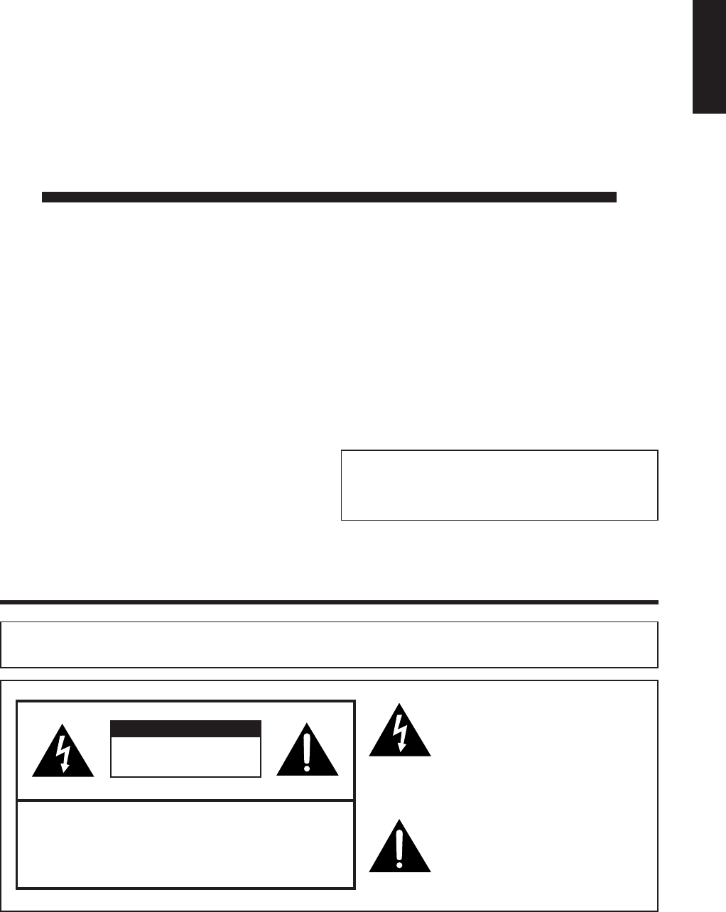
WARNING:TO REDUCE THE RISK OF FIRE OR ELECTRIC SHOCK, DO
NOT EXPOSE THIS PRODUCT TO RAIN OR MOISTURE.
CAUTION
RISK OF ELECTRIC SHOCK
DO NOT OPEN
CAUTION: TO REDUCE THE RISK OF ELECTRIC SHOCK,
DO NOT REMOVE COVER (OR BACK).
NO USER-SERVICEABLE PARTS INSIDE.
REFER SERVICING TO QUALIFIED SERVICE
PERSONNEL.
The lightning flash with arrow-head
symbol, within an equilateral
triangle, is intended to alert the user
to the presence of uninsulated
“dangerous voltage” within the
product’s enclosure that may be of
sufficient magnitude to constitute a
risk of electric shock to persons.
The exclamation point within a
triangle is intended to alert the user
to the presence of important
operating and maintenance
(servicing) instructions in the
literature accompanying the product.
IMPORTANT:
To aid reporting in case of loss or theft, please record
the TV’s model and serial numbers in the space
provided. The numbers are located at the rear of the
TV.
Model No.:
Serial No.:
• The illustrations and on-screen displays in this operation
manual are for explanation purposes and may vary slightly
from the actual operations.
• Some items may be grayed out. They are not selectable.
2
IMPORTANT INFORMATION
WARNING: FCC Regulations state that any unauthorized changes or modifications to this equipment not expressly
approved by the manufacturer could void the user’s authority to operate this equipment.
CAUTION: TO PREVENT ELECTRIC SHOCK, MATCH WIDE BLADE OF PLUG TO
WIDE SLOT, FULLY INSERT.
“Note to CATV system installer: This reminder is provided to call the CATV system installer’s attention to Article 820-40 of the
National Electrical Code that provides guidelines for proper grounding and, in particular, specifies that the cable ground shall be
connected to the grounding system of the building, as close to the point of cable entry as practical.”
This product utilizes tin-lead solder, and fluorescent lamp containing a small amount of mercury. Disposal of these
materials may be regulated due to environmental considerations. For disposal or recycling information, please contact
your local authorities or the Electronic Industries Alliance: www.eia.org
CAUTION:
DO NOT PLACE THIS PRODUCT ON AN UNSTABLE CART, STAND, TRIPOD, BRACKET, OR
TABLE. THE PRODUCT MAY FALL CAUSING SERIOUS PERSONAL INJURY AND SERIOUS
DAMAGE TO THE PRODUCT. USE ONLY WITH A CART, STAND, TRIPOD, BRACKET, OR TABLE
RECOMMENDED BY THE MANUFACTURER OR SOLD WITH THE PRODUCT. FOLLOW THE
MANUFACTURER’S INSTRUCTIONS WHEN INSTALLING THE PRODUCT AND USE MOUNTING
ACCESSORIES RECOMMENDED BY THE MANUFACTURER. A PRODUCT AND CART
COMBINATION SHOULD BE MOVED WITH CARE. QUICK STOPS, EXCESSIVE FORCE, AND
UNEVEN SURFACES MAY CAUSE THE PRODUCT AND CART COMBINATION TO OVERTURN.
INFORMATION:
This equipment has been tested and found to comply with the limits for a Class B digital device, pursuant to
Part 15 of the FCC Rules. These limits are designed to provide reasonable protection against harmful
interference in a residential installation. This equipment generates, uses and can radiate radio frequency
energy and, if not installed and used in accordance with the instructions, may cause harmful interference to
radio communications. However, there is no guarantee that interference will not occur in a particular
installation. If this equipment does cause harmful interference to radio or television reception, which can be
determined by turning the equipment off and on, the user is encouraged to try to correct the interference by
one or more of the following measures:
—Reorient or relocate the receiving antenna.
—Increase the separation between the equipment and receiver.
—Connect the equipment into an outlet on a circuit different from that to which the receiver is connected.
—Consult the dealer or an experienced radio/TV technician for help.
DECLARATION OF CONFORMITY
SHARP LIQUID CRYSTAL TELEVISION, MODEL LC-37GD4U
SHARP LIQUID CRYSTAL TELEVISION, MODEL LC-32GD4U
SHARP LIQUID CRYSTAL TELEVISION, MODEL LC-26GD4U
This device complies with Part 15 of the FCC Rules. Operation is subject to the following two conditions:
(1) This device may not cause harmful interference, and (2) this device must accept any interference
received, including interference that may cause undesired operation.
RESPONSIBLE PARTY:
SHARP ELECTRONICS CORPORATION
Sharp Plaza, Mahwah, New Jersey 07430-2135
TEL: 1-800-BE-SHARP
For Business Customers: URL http://www. sharpusa. com
CAUTION:
This product satisfies FCC regulations when shielded cables and connectors are used to connect the unit to other
equipment. To prevent electromagnetic interference with electric appliances such as radios and televisions, use
shielded cables and connectors for connections.

3
DEAR SHARP CUSTOMER
Thank you for your purchase of the Sharp Liquid Crystal Television. To ensure safety and many years
of trouble-free operation of your product, please read the IMPORTANT SAFETY INSTRUCTIONS
carefully before using this product.
IMPORTANT SAFETY INSTRUCTIONS
Electricity is used to perform many useful functions, but it can also cause personal injuries and property damage if
improperly handled. This product has been engineered and manufactured with the highest priority on safety. However,
improper use can result in electric shock and/or fire. In order to prevent potential danger, please observe the following
instructions when installing, operating and cleaning the product. To ensure your safety and prolong the service life of
your Liquid Crystal Television, please read the following precautions carefully before using the product.
1) Read these instructions.
2) Keep these instructions.
3) Heed all warnings.
4) Follow all instructions.
5) Do not use this apparatus near water.
6) Clean only with dry cloth.
7) Do not block any ventilation openings. Install in accordance with the manufacturer's instructions.
8) Do not install near any heat sources such as radiators, heat registers, stoves, or other apparatus (including
amplifiers) that produce heat.
9) Do not defeat the safety purpose of the polarized or grounding-type plug. A polarized plug has two blades with
one wider than the other. A grounding type plug has two blades and a third grounding prong. The wide blade or
the third prong are provided for your safety. If the provided plug does not fit into your outlet, consult an
electrician for replacement of the obsolete outlet.
10) Protect the power cord from being walked on or pinched particularly at plugs, convenience receptacles, and the
point where they exit from the apparatus.
11) Only use attachments/accessories specified by the manufacturer.
12) Use only with the cart, stand, tripod, bracket, or table specified by the manufacturer, or sold with the
apparatus. When a cart is used, use caution when moving the cart/apparatus combination to avoid
injury from tip-over.
13) Unplug this apparatus during lightning storms or when unused for long periods of time.
14) Refer all servicing to qualified service personnel. Servicing is required when the apparatus has been damaged
in any way, such as power-supply cord or plug is damaged, liquid has been spilled or objects have fallen into
the apparatus, the apparatus has been exposed to rain or moisture, does not operate normally, or has been
dropped.
15) Power Sources — This product should be operated only from the type of power source indicated on the
marking label. If you are not sure of the type of power supply to your home, consult your product dealer or local
power company. For products intended to operate from battery power, or other sources, refer to the operating
instructions.
16) Overloading — Do not overload wall outlets, extension cords, or integral convenience receptacles as this can
result in a risk of fire or electric shock.
17) Object and Liquid Entry — Never push objects of any kind into this product through openings as they may
touch dangerous voltage points or short-out parts that could result in a fire or electric shock. Never spill liquid
of any kind on the product.
18) Damage Requiring Service — Unplug this product from the wall outlet and refer servicing to qualified service
personnel under the following conditions:
a) When the AC cord or plug is damaged,
b) If liquid has been spilled, or objects have fallen into the product,
c) If the product has been exposed to rain or water,
d) If the product does not operate normally by following the operating instructions.
Adjust only those controls that are covered by the operating instructions as an improper adjustment of
other controls may result in damage and will often require extensive work by a qualified technician to
restore the product to its normal operation,
e) If the product has been dropped or damaged in any way, and
f) When the product exhibits a distinct change in performance – this indicates a need for service.
19) Replacement Parts — When replacement parts are required, be sure the service technician has used
replacement parts specified by the manufacturer or have the same characteristics as the original part.
Unauthorized substitutions may result in fire, electric shock, or other hazards.
20) Safety Check — Upon completion of any service or repairs to this product, ask the service technician to
perform safety checks to determine that the product is in proper operating condition.
21) Wall or ceiling mounting — When mounting the product on a wall or ceiling, be sure to install the product
according to the method recommended by the manufacturer.
4
IMPORTANT SAFETY INSTRUCTIONS
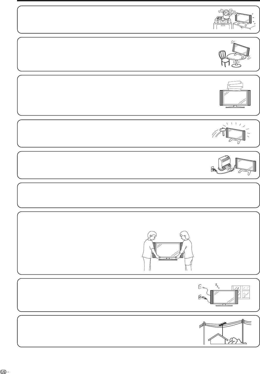
• Water and Moisture — Do not use this product near water – for example, near a bath tub,
wash bowl, kitchen sink, or laundry tub; in a wet basement; or near a swimming pool; and the
like.
• Stand — Do not place the product on an unstable cart, stand, tripod or table. Placing the
product on an unstable base can cause the product to fall, resulting in serious personal
injuries as well as damage to the product. Use only a cart, stand, tripod, bracket or table
recommended by the manufacturer or sold with the product. When mounting the product on
a wall, be sure to follow the manufacturer’s instructions. Use only the mounting hardware
recommended by the manufacturer.
• Ventilation — The vents and other openings in the cabinet are designed for ventilation. Do
not cover or block these vents and openings since insufficient ventilation can cause
overheating and/or shorten the life of the product. Do not place the product on a bed, sofa,
rug or other similar surface, since they can block ventilation openings. This product is not
designed for built-in installation; do not place the product in an enclosed place such as a
bookcase or rack, unless proper ventilation is provided or the manufacturer’s instructions are
followed.
• The Liquid Crystal panel used in this product is made of glass. Therefore, it can break when
the product is dropped or applied with impact. Be careful not to be injured by broken glass
pieces in case the panel breaks.
• The Liquid Crystal panel is a very high technology product with 3,147,264 thin film transistors, giving you fine picture
details.
Occasionally, a few non-active pixels may appear on the screen as a fixed point of blue, green or red. Please note
that this does not affect the performance of your product.
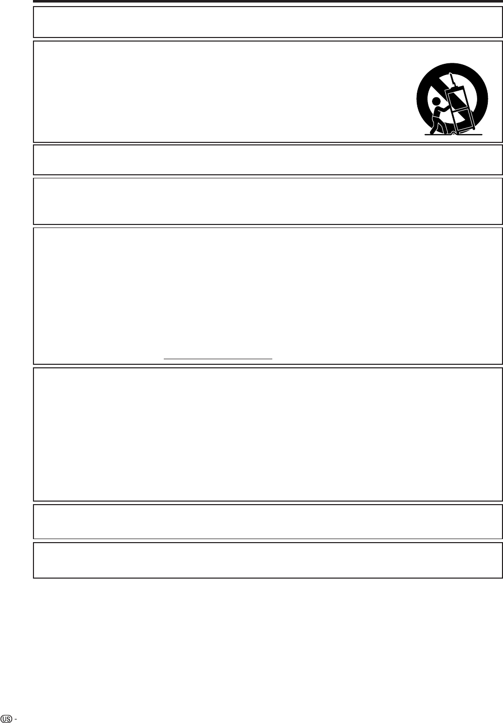
Precautions when transporting the Display
When transporting the Display, never carry it by holding onto the speaker. Be sure to always carry the Display by two
people holding it with two hands—one hand on each side of the Display.
• Heat — The product should be situated away from heat sources such as radiators, heat
registers, stoves, or other products (including amplifiers) that produce heat.
• Lightning — For added protection for this television equipment during a lightning
storm, or when it is left unattended and unused for long periods of time, unplug it
from the wall outlet and disconnect the antenna. This will prevent damage to the
equipment due to lightning and power-line surges.
• Power Lines — An outside antenna system should not be located in the vicinity of
overhead power lines or other electric light or power circuits, or where it can fall
into such power lines or circuits. When installing an outside antenna system, extreme
care should be taken to keep from touching such power lines or circuits as contact
with them might be fatal.
5
IMPORTANT SAFETY INSTRUCTIONS
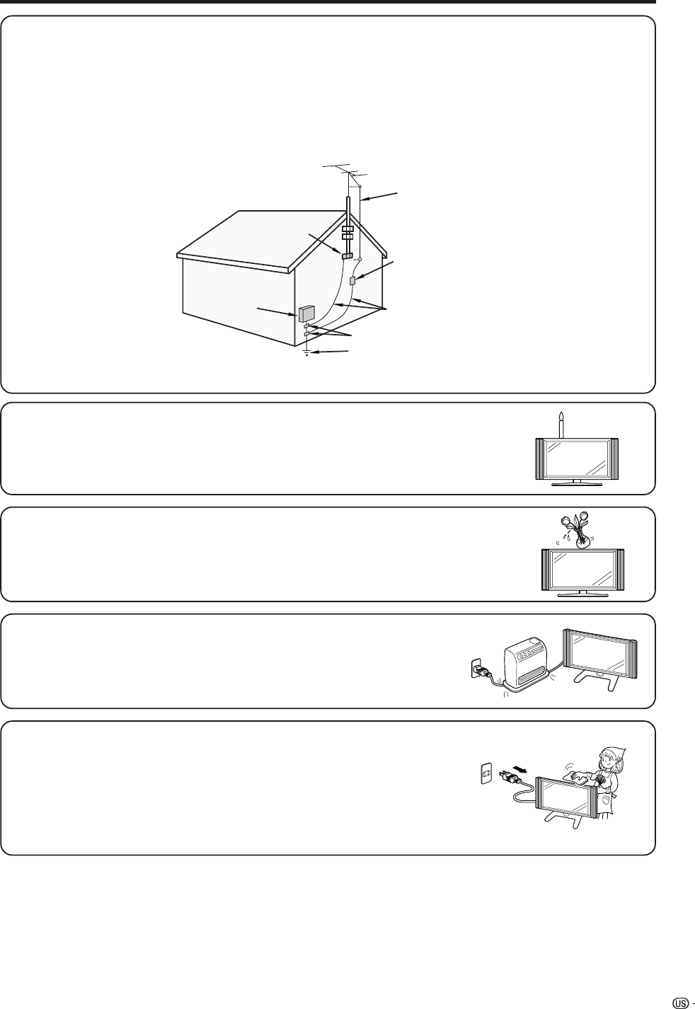
• Outdoor Antenna Grounding — If an outside antenna is connected to the television equipment, be sure the antenna
system is grounded so as to provide some protection against voltage surges and built-up static charges.
Article 810 of the National Electrical Code, ANSI/NFPA 70, provides information with regard to proper grounding of
the mast and supporting structure, grounding of the lead-in wire to an antenna discharge unit, size of grounding
conductors, Iocation of antenna-discharge unit, connection to grounding electrodes, and requirements for the
grounding electrode.
EXAMPLE OF ANTENNA GROUNDING AS PER
NATIONAL ELECTRICAL CODE, ANSI/NFPA 70
ANTENNA
LEAD IN
WIRE
ANTENNA
DISCHARGE UNIT
(NEC SECTION 810-20)
GROUNDING CONDUCTORS
(NEC SECTION 810-21)
GROUND CLAMPS
POWER SERVICE GROUNDING
ELECTRODE SYSTEM
(NEC ART 250, PART H)
GROUND
CLAMP
ELECTRIC
SERVICE
EQUIPMENT
NEC —NATIONAL ELECTRICAL CODE
• To prevent fire, never place any type of candle or flames on the top or near the TV
set.
• To prevent fire or shock hazard, do not expose this product to dripping or splashing.
No objects filled with liquids, such as vases, should be placed on the product.
• To prevent fire or shock hazard, do not place the AC power cord under the TV set
or other heavy items.
• Turn off the main power and unplug the AC cord from the wall outlet before handling.
• Use a soft cloth and gently wipe the surface of the display panel. Using a hard
cloth may scratch the panel surface.
• Use a soft damp cloth to gently wipe the panel when it is really dirty.
(It may scratch the panel surface when wiped strongly.)
• If the panel is dusty, use an anti-static brush, which is commercially available, to
clean it.
• To protect the panel, do not use a dirty cloth, liquid cleaners or chemical cloth to
clean it, such materials may damage the panel surface.

6
Contents
IMPORTANT INFORMATION ………………………1
DEAR SHARP CUSTOMER …………………………3
IMPORTANT SAFETY INSTRUCTIONS ……………3
Contents ………………………………………………6
Trademarks ……………………………………………7
COPYRIGHT AND LICENSE NOTICE ……………7
Patent Notice …………………………………………7
Supplied accessories ………………………………8
Preparation ……………………………………………9
Where to place the TV …………………………… 9
Setting the TV ………………………………… 10
Attaching speakers …………………………… 11
Removing the stand …………………………… 12
Setting the Display on the wall ……………… 12
Inserting the batteries ………………………… 13
Using the remote control unit ………………… 13
Cautions regarding remote control unit … 13
Part names ………………………………………… 14
Display ………………………………………… 14
Remote control unit …………………………… 16
Watching TV ……………………………………… 17
Antennas ……………………………………… 17
Cable TV converter/VCR connection ………… 17
Outdoor antenna connection ………………… 19
Turning on the power ………………………… 20
Turning off the power ………………………… 20
Initial setup ……………………………………… 21
Changing channels Analog-TV ……………… 22
Changing channels Digital-TV ……………… 22
Changing volume/sound ……………………… 23
Setting MTS/SAP stereo mode ……………… 24
Connecting Digital Cable Module …………… 25
Basic adjustment settings ……………………… 26
AV input mode menu items …………………… 26
PC input mode menu items …………………… 26
EZ setup ………………………………………… 27
Channel setup ………………………………… 28
Favorite channel setting ……………………… 30
Language setting ……………………………… 30
Antenna Setup-DIGITAL ……………………… 31
Picture adjustments …………………………… 32
OPC setting ………………………………… 33
C.M.S. (Color Management System) …… 33
Color temperature ………………………… 34
Black ……………………………………… 34
3D-Y/C ……………………………………… 34
Monochrome ……………………………… 35
Film mode (3:2 pull-down) ……………… 35
I/P Setting ………………………………… 35
Sound adjustment ……………………………… 36
Dolby virtual …………………………………… 36
Power control …………………………………… 37
Power control for AV source ……………… 37
Power control for PC source ……………… 37
Digital Setup …………………………………… 38
Video setup ………………………………… 38
Audio setup ………………………………… 39
Using memory card ……………………………… 40
Important notes on using memory card …… 40
Card Setup mode menu items ……………… 42
Recording a still image ……………………… 44
Displaying a still image ……………………… 44
Displaying slide show ………………………… 44
Setting/unprotecting Slide Show …………… 45
My Program …………………………………… 45
Audio Select …………………………………… 45
Protecting/unprotecting still picture files …… 46
Deleting a still image file ……………………… 46
Deleting all still image files …………………… 46
Recording a motion picture …………………… 47
Displaying a motion picture ………………… 47
Rec. Mode ……………………………………… 47
Pre Record ……………………………………… 48
Repeat Play …………………………………… 48
Protecting/unprotecting motion picture files … 48
Deleting a motion picture file ………………… 49
Deleting all motion picture files ……………… 49
Format …………………………………………… 49
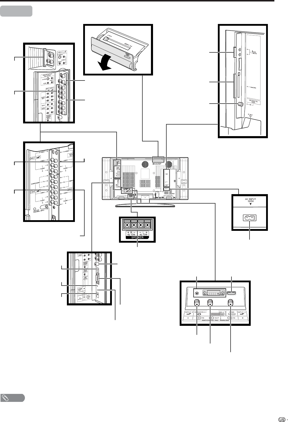
Using external equipment ……………………… 50
Displaying an external equipment image …… 50
Connecting a DVD player …………………… 51
Connecting a VCR …………………………… 52
Connecting a game console
or camcorder ……………………………… 52
Connecting a Digital TV STB ………………… 53
Connecting HDMI equipment …………… 54
Displaying an image from HDMI
equipment ………………………………… 54
Connecting a PC ……………………………… 55
Connecting D-VHS Decks
(i.LINK connection) ……………………… 56
About i.LINK ……………………………… 56
i.LINK connection ………………………… 56
Connecting two or more D-VHS decks … 56
Setting the recording mode ……………… 57
Setting the Stand-by Mode ……………… 57
Selecting a D-VHS deck (i.LINK) ………… 58
Disabling the TV’s operation of
a D-VHS deck (i.LINK) ………………… 58
Deleting a preset D-VHS deck (i.LINK) … 59
Controlling an i.LINK device……………… 59
Automatic input switching to i.LINK …… 60
Recording digital programs
with a D-VHS deck (i.LINK)…………… 61
Useful adjustment settings ……………………… 62
Image position (AV input mode only) ……… 62
Moving the picture on the screen …………… 62
Connecting external speakers ……………… 63
Audio Quality Control ………………………… 64
Auto Sync. adjustment (PC input mode only) … 65
Fine Sync. adjustment (PC input mode only) … 65
Input Select …………………………………… 66
Input label ……………………………………… 67
Picture flip ……………………………………… 67
AV MODE ……………………………………… 68
View mode for 4:3 Programs ………………… 68
View mode (for PC input mode) ……………… 69
Input signal (for PC input mode) …………… 70
Digital Noise Reduction ……………………… 70
Audio only ……………………………………… 70
Output Select …………………………………… 71
Quick shoot …………………………………… 71
Sleep timer ……………………………………… 71
Title Display Type ……………………………… 72
Closed caption ………………………………… 73
Caption Size ……………………………… 74
Font Style …………………………………… 74
Foreground Color ………………………… 75
Foreground Opacity ……………………… 75
Background Color ………………………… 75
Background Opacity ……………………… 76
Character Edge …………………………… 76
7
Contents
Secret number setting for parental control
(AV input mode only) ……………………… 77
Parental control (setting V-CHIP level) ……… 79
How to temporarily release
the V-CHIP BLOCK ……………………… 83
Reactivating the temporarily released
V-CHIP BLOCK …………………………… 83
Center Channel Input ………………………… 84
Other viewing options …………………………… 85
Viewing a list of Digital broadcast channels … 85
Viewing information of the program ………… 85
Twin picture functions ………………………… 86
Presetting remote control function …………… 86
Appendix ………………………………………… 92
Troubleshooting ………………………………… 92
PC compatibility chart ………………………… 93
RS-232C port specifications ………………… 94
Specifications ………………………………… 96
Optional accessory …………………………… 96
Dimensional drawings …………………………… 97
COPYRIGHT AND LICENSE NOTICE
• It is the intent of Sharp that this product be used in full compliance with the copyright laws of the United States and that
prior permission be obtained from copyright owners whenever necessary.
• This product incorporates copyright protection technology that is protected by U.S. patents and other intellectual property
rights. Use of this copyright protection technology must be authorized by Macrovision, and is intended for home and
other limited viewing uses only unless otherwise authorized by Macrovision. Reverse engineering or disassembly is
prohibited. U. S. Patent Nos. 4,631,603; 4,577,216; 4,819,098; 4,907,093; 5,315,448; 6,381,747; and 6,516,132.
• This digital television is capable of receiving analog basic, digital basic and digital premium cable television programming
by direct connection to a cable system providing such programming. A security card provided by your cable operator is
required to view encrypted digital programming. Certain advanced and interactive digital cable services such as video-
on-demand, a cable operator's enhanced program guide and data-enhanced television services may require the use of
a set-top box. For more information call your local cable operator.
Trademarks
• Manufactured under license from Dolby Laboratories. “Dolby”, “Pro Logic” and the double-D symbol
are trademarks of Dolby Laboratories.
• Manufactured under license from BBE Sound, Inc.
Licensed by BBE Sound, Inc. under USP4638258, 5510752 and 5736897. BBE and BBE symbol are registered
trademarks of BBE Sound, Inc.
• “HDMI, the HDMI logo and High-Definition Multimedia Interface are trademarks or registered trademarks of HDMI
Licensing LLC.”
8
Supplied accessories
Make sure the following accessories are provided with the product.
NOTE
• Always use the AC cord supplied with the LCD-TV.
RF cable (g1)
QCNW-A342WJZZ
Pages 18 and 19
Remote control unit (g1)
RRMCGA264WJSA
Page 13
“AAA” size battery (g2)
Page 13
LC-26GD4U
LC-32GD4U
LC-37GD4U
QACCDA019WJPZ
Page 10
AC cord (g1)
TINS-B241WJZZ
Operation manual (g1)Cable clamp (g1)
Speaker unit (g1)
LHLDW0110CEZZ
Page 10
Left speaker
LC-37GD4U: DSP-ZA079UJ07
LC-32GD4U: DSP-ZA076UJ07
Page 11
Right speaker
LC-37GD4U: DSP-ZA079UJ08
LC-32GD4U: DSP-ZA076UJ08
Page 11
Bracket unit (g1)
LC-37GD4U/LC-32GD4U:
GCOVAA856WJKB
Page 11
Only included with the LC-32GD4U
and LC-37GD4U.
The LC-26GD4U is shipped with the
speakers attached.
The LC-26GD4U is shipped with the speakers attached.
**
** **
*
Speaker unit
Color Q’ty
—4
SILVER 2
Bracket unit BLACK 2
Parts number
LX-BZA063WJ01
XEBSN40P08000
XEBS940P12000
* The parts number for screws
Angle —2LHLDZA375WJKA
** The parts number for speaker unit
9
Setting the TV in place
Handling the Display
CAUTION
• Do not remove the stand and speaker from the Display unless
using an optional bracket to mount it.
• Keep enough space above and behind the Display.
• When you move TV, carry out by two people or more than it.
• When you move the Display, hold the portion of the Display, not the
speaker.
Where to place the TV
First select the location where to place the TV.
Selecting the location of the TV
• Select a place with no direct sunlight and good ventilation.
Display
1
2
4 inches
(10 cm)
or more
Preparation
CAUTION
Adjust the screen with both hands. Put one
hand on the Display and tilt the screen while
steadying the stand with your other hand.
LC-37GD4U
Maximum Degree of Adjustment
Up Down Left/Right
6˚ 2˚ 10˚ each
LC-32GD4U 6˚ 2˚ 10˚ each
LC-26GD4U 10˚ 5˚ 25˚ each
10
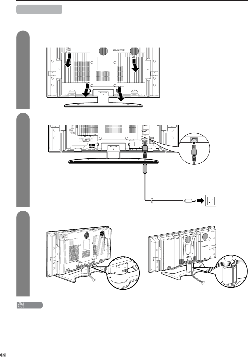
Display (rear view)
Setting the TV
After putting the Display in place, connect the AC cord. Use the cable clamp for bundling the cables.
Preparation
Connecting the AC cord to the Display
1
2
3
Removing the terminal cover
Bundling the cables with the clamp
CAUTION
•TO PREVENT RISK OF ELECTRIC SHOCK, DO NOT TOUCH UN-INSULATED PARTS OF ANY CABLES WITH THE
AC CORD CONNECTED.
Press down the hooks
to remove the cover
toward you.
AC cord (with ferrite core)
for LC-32GD4U/LC-37GD4U
Cable clamp
for LC-26GD4U
11
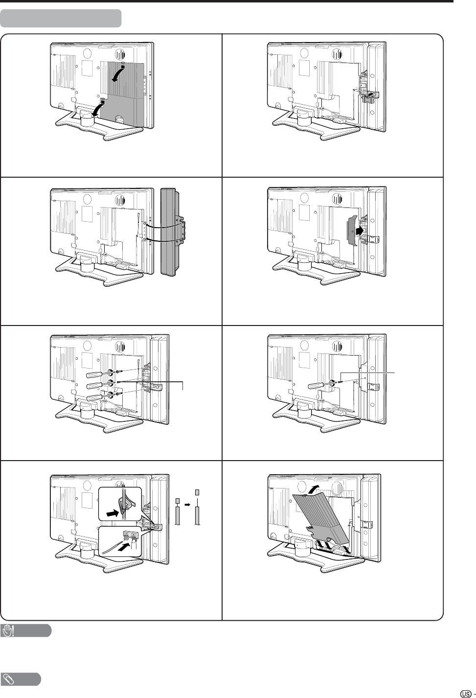
Attaching speakers
Preparation
NOTE
• Perform the same steps for right speaker.
• To attach the speakers, perform the steps in reverse order.
CAUTION
• Do not remove the stand and speaker from the Display unless using an optional bracket to mount it.
• Before performing work spread cushioning over the base area to lay the Display on. This will prevent it from
being damaged.
1
2
3
6
5
4
7
8
Remove the terminal cover as shown in the
illustration.
Fasten the screw.
Fasten the speaker cable with the holder. Connect
the ends of the cable to the speaker terminals as
shown in the illustration.
Insert the projecting bulges on the side of the
speakers into the corresponding slots in the
display.
Attach the speaker terminal cover.
Fasten the bracket with the screw.
Attach the terminal cover as shown in the
illustration.
Align nub of the bracket with the groove and slot it
into place.
The illustration shows the LC-32GD4U.
Screw
(BLACK)
Screw
(SILVER)
12
Preparation
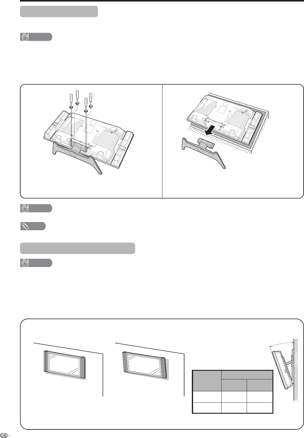
Removing the stand
Before detaching (or attaching) stand, unplug the AC cord from the AC input terminal.
CAUTION
•Do not remove the stand from the Display unless using an optional wall mount bracket to mount it.
Before attaching/detaching stand
• Before performing work make sure to turn off the TV.
• Before performing work spread cushioning over the base area to lay the Display on. This will prevent it from
being damaged.
NOTE
• To attach the stand, perform the above steps in reverse order.
2
Detach the stand from the Display.
(Hold the stand so it will not drop from the edge of
the base area.)
1
Unfasten the four screws used to secure the
stand in place.
Setting the Display on the wall
CAUTION
• Installing the Liquid Crystal Television requires special skill that should only be performed by qualified service
personnel. Customers should not attempt to do the work themselves. SHARP bears no responsibility for improper
mounting or mounting that results in accident or injury.
Using an optional bracket to mount the Display
• You can ask a qualified service personnel about using an optional AN-37AG2 bracket to mount the Display
to the wall.
• Carefully read the instructions that come with the bracket before beginning work.
Vertical mounting Angular mounting
Hanging on the wall
AN-37AG2 wall mount bracket. (See the bracket instructions
for details.)
About setting the Display angle
LC-37/32/26GD4U
•
You can set the Display on the wall
up to 20 degrees forward when the
speakers are attached and up to
20 degrees forward when the
speakers are not attached. Do not
set the angle outside those ranges.
CAUTION
• Do not remove the stand and speaker from the Display unless using an optional bracket to mount it.
•
We do not recommend attaching
the LC-26GD4U to a wall surface.
Angle of Display
LC-37GD4U
With Speakers
Removed
With Speakers
Attached
10˚ 10˚
LC-32GD4U 20˚ 20˚
13
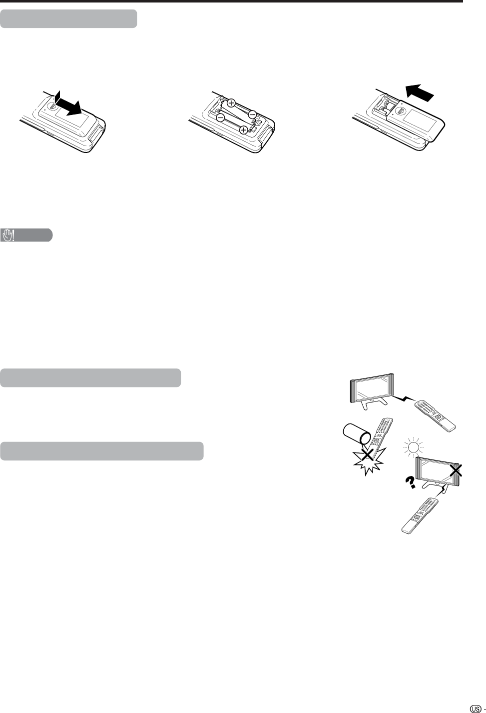
1Open the battery cover. 2Insert two “AAA” size batteries
(supplied with the product).
• Place the batteries with their terminals
corresponding to the (e) and (f)
indications in the battery compartment.
3Close the battery cover.
CAUTION
Improper use of batteries can result in chemical leakage or explosion. Be sure to follow the instructions below.
• Place the batteries with their terminals corresponding to the (e) and (f) indications.
• Do not mix batteries of different types. Different types of batteries have different characteristics.
• Do not mix old and new batteries. Mixing old and new batteries can shorten the life of new batteries or cause
chemical leakage in old batteries.
• Remove batteries as soon as they are worn out. Chemicals that leak from batteries can cause a rash. If you
find any chemical leakage, wipe thoroughly with a cloth.
• The batteries supplied with this product may have a shorter life expectancy due to storage conditions.
• If you will not be using the remote control unit for an extended period of time, remove batteries from it.
Inserting the batteries
If the remote control fails to operate Liquid Crystal Television functions, replace the batteries in the remote
control unit.
Using the remote control unit
Use the remote control unit by pointing it towards the remote control sensor on
the Display. Objects between the remote control unit and the remote control
sensor may prevent proper operation.
Cautions regarding remote control unit
• Do not expose the remote control unit to shock.
In addition, do not expose the remote control unit to liquids, and do not place
in an area with high humidity.
• Do not install or place the remote control unit under direct sunlight.
The heat may cause deformation of the remote control unit.
• The remote control unit may not work properly if the remote control sensor on
the Display is under direct sunlight or strong lighting. In such cases, change
the angle of the lighting or the Display, or operate the remote control unit
closer to the remote control sensor.
Preparation
14
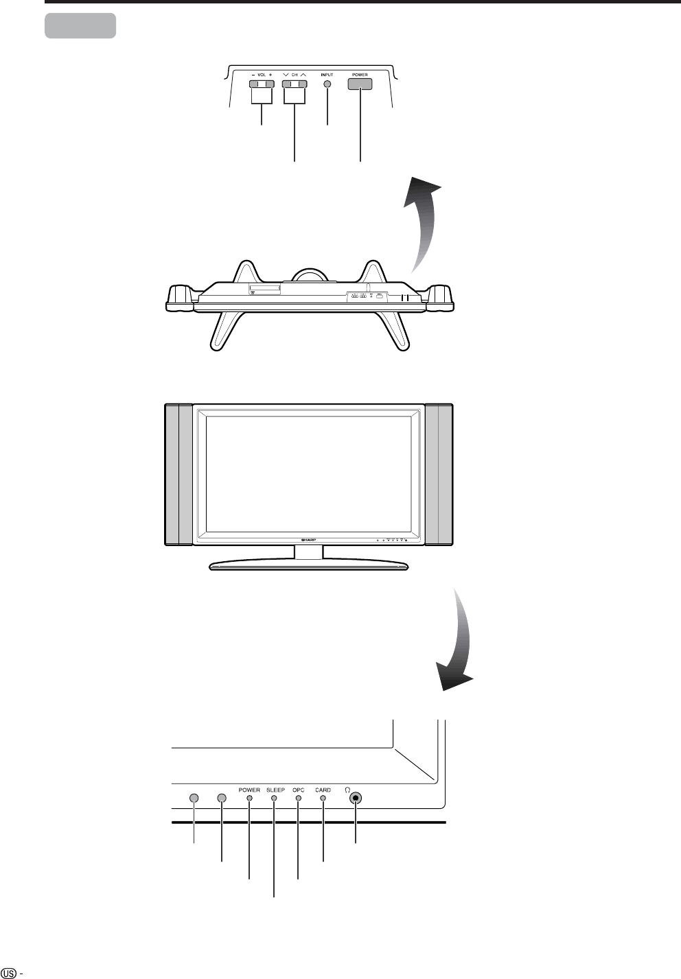
Part names
POWER indicator
OPC sensor
Display
POWER button
INPUT
button
VOLUME buttons
(VOLl/k)
CHANNEL buttons
(CHs/r)
Remote control sensor
*OPC: Optical Picture Control
(See page 33.)
SLEEP indicator
OPC indicator
Headphone jack
CARD indicator
* The examples use throughout this manual are based on the 32GD4U model.
15
LC-37GD4U
LC-32GD4U
LC-26GD4U
Part names
Display
*Press RESET if the system cannot return to its
original state after performing various operations.
• AV MODE resets to DYNAMIC (Fixed)
• TV channel returns to initial channel setting (Air:2ch, Cable:1 or 2ch)
• Twin picture resets to normal
• Audio setting initializes
• Dolby virtual resets to off
• Image position initializes
** Press SYSTEM RESET if the system does not operate after starting up.
NOTE
• Pressing RESET will not work if the System is in standby mode (indicator lights red).
• Pressing RESET will not delete channel preset or secret number. See page 66 for clearing the secret number when you
know it. See page 100 for initializing to the factory preset values when you forget your secret number.
RESET*
INPUT 3
terminals
SYSTEM RESET**
ANALOG A IN terminal
ANALOG B IN terminal
ANALOG A OUT terminal
DC OUTPUT
terminal
(Terminal for expanded
functionality in the near
future.)
EXTERNAL SPEAKER terminals
AC INPUT
terminal
RS-232C
terminal
INPUT 2 terminals
INPUT 1
terminals
INPUT 5 terminals INPUT 4 terminal
DIGITAL AUDIO OUTPUT
terminal CENTER CHANNEL
INPUT terminal
MONITOR OUTPUT
terminals
i.LINK terminals
CableCARD slot
ANT/CABLE 75 q
DIGITAL terminal
* Instead of AIR IN and CABLE
IN terminals, the LC-26GD4U
has an ANT/CABLE 75 q
DIGITAL terminal.
* This terminal
looks different on
the LC-26GD4U.
INPUT 3
terminals
INPUT 1
terminals
MONITOR
OUTPUT
terminals
INPUT 2 terminals
16
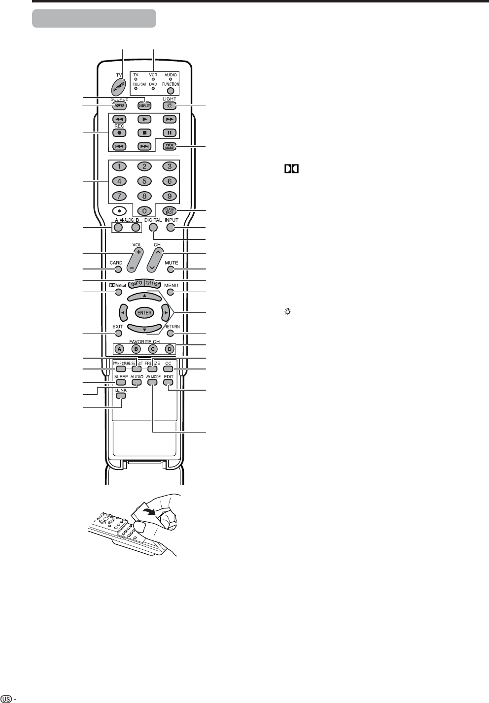
Part names
Remote control unit
3
2
117
5
6
4
7
20
18
19
21
22
23
824
925
10 26
11 28
29
30
13
14
15
12
31
16
33
27
32
1 TV POWER: Switches the Liquid Crystal Television
power on or Standby. (See page 20.)
2 DISPLAY: Displays the channel information.
3 SOURCE POWER: Turns the power of the external
equipment on and off.
4 External equipment operational buttons: Operates
the external equipment.
50 – 9: Sets the channel.
6 A-ANALOG-B: Each button selects the corresponding
antenna.
7VOL
kk
kk
k/ll
ll
l:Sets the volume. (See page 23.)
8 CARD: Switches to card mode.
9 INFO: Displays the program information screen. (See
page 85.)
10 Virtual: Select Virtual Dolby Surround settings. (See
page 36.)
11 EXIT: Turns off the menu screen.
12 SELECT: Selects the active screen. (See page 85.)
13 TWIN PICTURE: Sets the twin picture mode.
Press again to return to normal screen. (See page
86.)
14 SLEEP: Sets the sleep timer. (See page 71.)
15 AUDIO: Selects the MTS/SAP. (See page 24.)
16 i.LINK: Displays the i.LINK panel. (See page 59.)
17 FUNCTION: Switches the remote control for TV, CBL/
SAT, VCR, DVD and AUDIO operation. Indicator lights
up for the current mode. (See page 87 to 91 for details.)
18 :When pressed all buttons on the remote control unit
will light. The lighting will turn off if no operations are
performed within about 5 seconds. This button is used
for performing operations in dark places.
19 VIEW MODE: Selects the screen size. (See pages 69
and 71.)
20 FLASHBACK: Returns to the previous channel or input
external mode. (See page 22.)
21 INPUT: Selects a Liquid Crystal Television input source.
(TV, INPUT 1, INPUT 2, INPUT 3, INPUT 4, INPUT 5,
Card) (See pages 50 and 66.)
22 DIGITAL: Receives digital broadcasts.
23 CH rr
rr
r/ss
ss
s:Selects the channel.
24 MUTE: Mutes the sound. (See page 23.)
25 CH LIST: Displays the channel list screen.
26 MENU: Displays the menu screen.
27 a/b/c/d:Selects a desired item on the screen.
28 RETURN: Returns to the previous menu screen.
29 FAVORITE CH
A,B,C,D: Selects four preset favorite channels in four
different categories. (See page 30 for details.)
While watching, you can toggle the selected channels
by pressing A, B, C and D.
30 FREEZE: Sets the still image. Press again to return to
normal screen. (See page 86.)
31 CC: Displays captions during closed-caption source.
(See page 73.)
32 EDIT: Registers favorite channel.
33 AV MODE: Selects an audio or video setting. (See
page 68.) (AV mode: STANDARD, MOVIE, GAME,
USER, DYNAMIC (Fixed), DYNAMIC. PC mode:
STANDARD, USER.)
17
Watching TV
Simple operations for watching a TV program
Antennas
To enjoy a clearer picture, use an outdoor antenna. The following is a brief explanation of the types of connections
that are used for a coaxial cable. If your outdoor antenna uses a 75-ohm coaxial cable with an F-type connector,
plug it into the antenna terminal at the rear of the AVC System.
NOTE
• The antenna and the cable converter cannot be connected at the same time.
1. A 75-ohm system is generally a round cable with F-type
connector that can easily be attached to a terminal without
tools (Commercially available).
2. A 300-ohm system is a flat “twin-lead” cable that can be
attached to a 75-ohm terminal through a 300/75-ohm
adapter (Commercially available).
F-type connector
75-ohm coaxial cable (round)
300-ohm twin-lead cable (flat)
•Be sure to connect the antenna or the cable converter as follows. Signal reception may fail if improperly connected.
• Be sure to remember what kind of connection is made with your System.
• The connection type will determine whether to select “Air” or “Cable” for both ANT-A and B when configuring “Air/Cable”
settings.
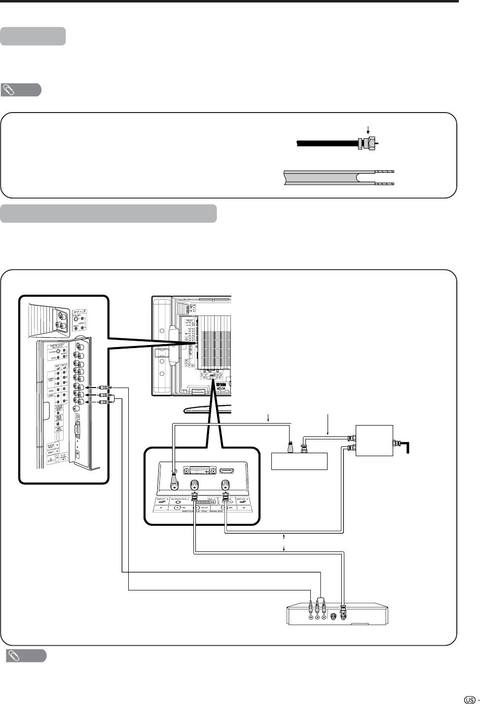
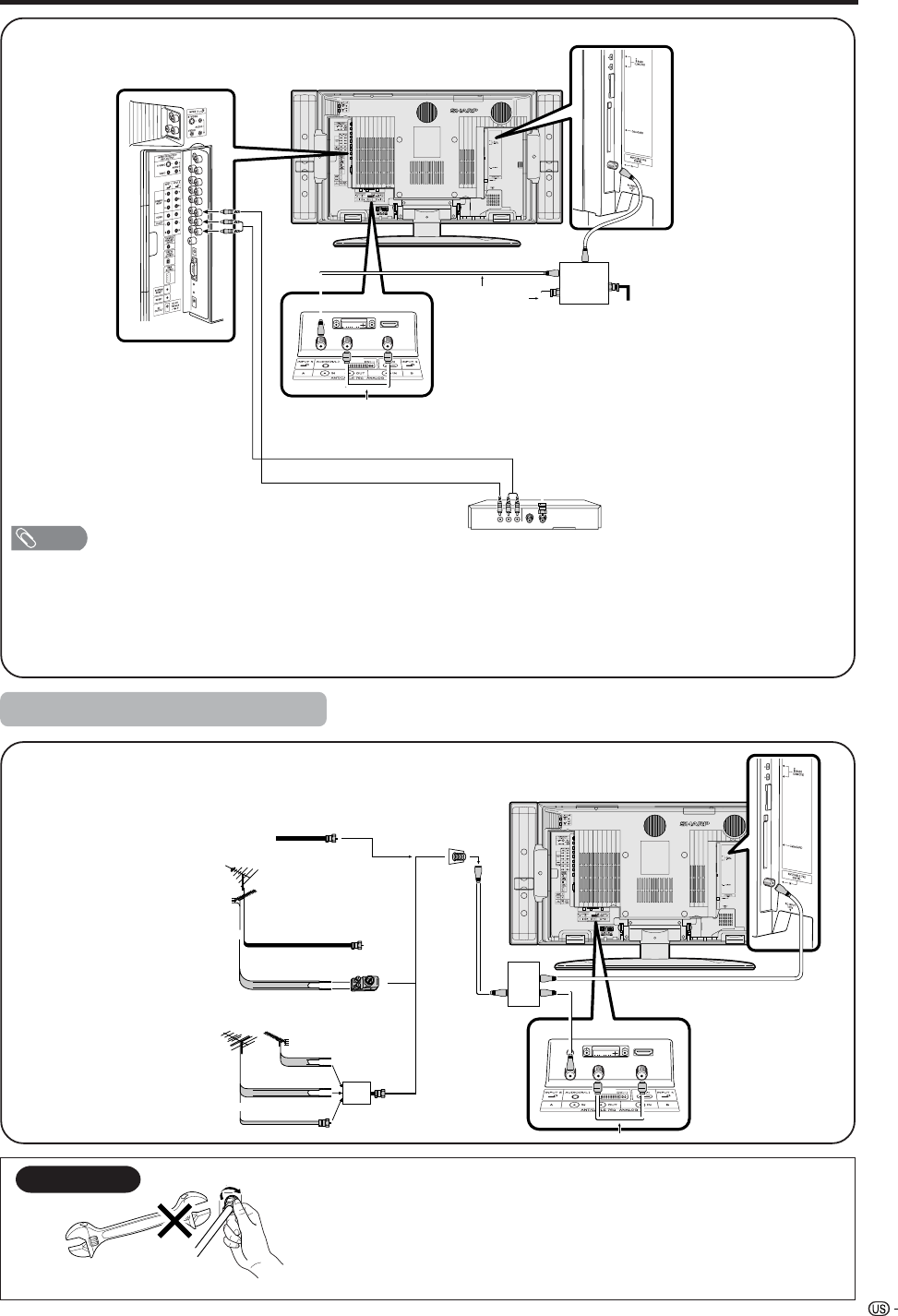
Cable TV converter/VCR connection
VIDEO AUDIO OUT IN
Cable lead-in
Cable TV converter
(commercially available)
OUT IN
2-way
signal splitter
(commercially
available)
Coaxial Antenna Cable (commercially available)
Coaxial Antenna Cable (commercially available)
Video Cable (commercially available)
Audio Cable (commercially available)
VCR
A-1. Connecting with cable TV Converter and VCR
NOTE
• Be sure to remember what kind of connection is made with your System.
• Shown here is the preferred method of connecting a VCR and CATV Converter to your TV if you are in an area with good
signal reception. This way you can view either TV programs or VCR tapes and not be concerned about the position of the
VCR’s TV/VCR switch and you can enjoy stereo tape playback from a stereo VCR.
• While in STANDBY, no signal outputs from ANT-A OUT.
18
Watching TV
A-2. Connecting with cable converter using AUX terminals for audio and video output.
(If your cable TV converter has both RF OUTPUT and AUX terminals, it is recommended to connect it as
shown in example A-1.)
VIDEO AUDIO OUT IN
Cable lead-in
IN
signal splitter
(commercially
available)
OUT
VIDEO AUDIO
Coaxial Antenna Cable (commercially available)
RF Cable (Supplied)
Cable TV Converter
VCR
Video Cable (commercially available)
Audio Cable (commercially available)
NOTE
• Be sure to remember what kind of connection is made with your System.
• Shown here is the preferred method of connecting a VCR and CATV Converter to your TV if you are in an area with good
signal reception. This way you can view either TV programs or VCR tapes and not be concerned about the position of the
VCR’s TV/VCR switch and you can enjoy stereo tape playback from a stereo VCR.
B. Connecting with Cable Converter without VCR
Cable lead-in
Cable TV converter
(commercially available)
OUT IN
signal splitter
(commercially
available)
Coaxial Antenna Cable (commercially available)
Coaxial Antenna Cable
(commercially available)
NOTE
• Be sure to remember what kind of connection is made with your System.
• Switching between ANALOG-A and ANALOG-B is possible by pressing the A-ANALOG-B button on the remote control.
• A good color picture depends on a good TV signal. So does good multi-channel sound. Ask your dealer for advice on
how to install your outdoor antenna to receive the best possible signal.
• If you subscribe to Cable TV or have a central antenna for your building, you may not need an outdoor antenna.
Cable converter/VCR connection (continued)
19
Watching TV
C. Connecting Antenna Cable with VCR
NOTE
• Be sure to remember what kind of connection is made with your System.
• Shown here is the preferred method of connecting a VCR to your TV if you are in an area with good signal reception. This
way you can view either TV programs or VCR tapes and not be concerned about the position of the VCR’s TV/VCR switch
and you can enjoy stereo tape playback from stereo VCR.
• If your lead cable is a 300-ohm twin-lead cable or UHF/VHF separate cable, use a 300/75-ohm adapter or combiner
(output side is 75-ohm coaxial) to connect to the TV (see below).
VIDEO AUDIO OUT IN
Cable lead-in
VCR
signal splitter
(commercially
available)
Coaxial Antenna Cable
(commercially available)
Video Cable (commercially available)
Audio Cable (commercially available)
RF Cable (Supplied)
300-ohm twin-lead (flat)
300-ohm twin-lead
75-ohm coaxial cable (round)
75-ohm coaxial cable
Cable TV lead-In
or
IN OUT
300-ohm
twin-lead
VHF
ANTENNA
UHF
ANTENNA
Combiner
(commercially
available)
or
Home Antenna
terminal (75-ohm)
300/75-ohm adapter
(commercially available)
RF Cable (Supplied)
Coaxial cable
(commercially
available)
Cable without a CATV
converter
Combination
VHF/UHF antenna
Separate VHF/UHF
antenna
Connecting Antenna Cable
Outdoor antenna connection
F-type connector
75-ohm coaxial cable
When connecting the RF cable to the TV set, do not tighten
F-type connector with tools.
If tools are used, it may cause damage to your TV set.
(The breaking of internal circuit, etc.)
F-type connector should be finger-tightened only.
NOTICE
20
Display
POWER
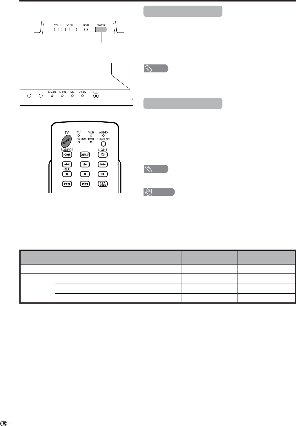
Turning on the power
ON
Display status indicator
w/o CableCARD
POWER indicator
Press POWER on the Display.
• POWER indicator (Blue): The TV is on. (After a few seconds, a window
appears with sound.)
• POWER indicator (Off): The TV is in standby. Press TV POWER on the
remote control.
NOTE
• The initial setup starts when the TV powers on for the first time. If the TV
has been turned on before, the EZ setup will not be invoked. See page
XX to try EZ setup from the Setup menu.
Turning off the power
Press TV POWER on the remote control.
• The TV enters standby mode and the image on the screen disappears.
• The POWER indicator on the Display gradually turns off.
Press POWER on the Display.
• The POWER indicator on the Display gradually turns off.
• The Power will not turn off unless the AC cord is pulled out from the wall
outlet.
NOTE
• If you are not going to use this TV for a long period of time, be sure to
remove the AC cord from the power outlet.
Watching TV
CAUTION
•Please do not unplug the AC cord when the POWER indicator is
red.
When CableCARD
inserted
Standby
OFF (Standby)
TV Guide On Screen function is downloading data
CableCARD is downloading data.
Lighting (Blue)
Lights off
Lighting (Red)
Lighting (Blue)
Lights off
Lighting (Red)
Lighting (Red)—
21
Watching TV
Press a/b to select the desired language
listed on the screen, and then press ENTER.
Press c/d to select “Air” or “Cable” for
ANALOG-A, then press a/b to move down.
Press c/d to select “Air” or “Cable” for
ANALOG-B.
Press c/d to select “Air” or “Cable” for
DIGITAL (Cable), then press a/b to move
down.
Press ENTER to enter the setting.
• This operation makes the System search for
both ANALOG-A and B.
• There are 3 kinds of CATV system, including
Standard, HRC and IRC. Select the one
matches to your TV. Select Auto when you do
not know which one to select.
Initial setup
When you turn on the TV for the first time, it will automatically memorize the broadcasting channels where you
live. Perform the following steps before you press TV POWER on the remote control unit.
1. Insert the batteries into the remote control unit. (See page 13.)
2. Connect the antenna cable to the Display. (See pages 17 to 19.)
3. Plug in the AC cord to the AC outlet. (See page 10.)
Channel search
Channel auto search makes the System look for all
channels viewable in the set area.
3
1
2
Language
TV Guide On Screen
Air/Cable
CH Search
English
Español
Français
Language
Air/Cable
CH Search ANALOG-A
ANALOG-B
Air
Air
DIGITAL Cable (STD)
CH Search
ANALOG-A
[ ]25Air [ ]20Found
CH Search
ANALOG-B
[ ]25Cable [ ]20Found
Language
Air/Cable
CH Search ANALOG-A
ANALOG-B
Air
Air
DIGITAL Cable STD
Example
2
ANALOG-A Air
Audio : MONO
Language setting
Select from among 3 languages: English, French and
Spanish.
Antenna setting
Make sure what kind of connection is made with your TV
when selecting “Air” or “Cable” for both ANALOG-A and B.
Example
NOTE
• Make sure what kind of connection is made with your TV
when selecting “Air” or “Cable” for both ANALOG-A, B
and DIGITAL.
• If no channel is found, make sure what kind of connection
is made with your TV and try EZ setup again (see page
27).
Press c/d to select “Yes” for ANALOG-A,
then press a/b to move down.
Press c/d to select “Yes” for ANALOG-B,
then press a/b to move down.
Press c/d to select “Yes” for DIGITAL (AIR/
Cable), and press UP/DOWN to move down.
Select “Search Start”, and then press
ENTER.
ANALOG-A
Yes
ANALOG-B
No
Yes No
DIGITAL Yes No
Search Start
Language
Air/Cable
CH Search
CH Search
DIGITAL
[ ]25Cable [ ]20Found
DIGITAL (Cable)
22
Watching TV
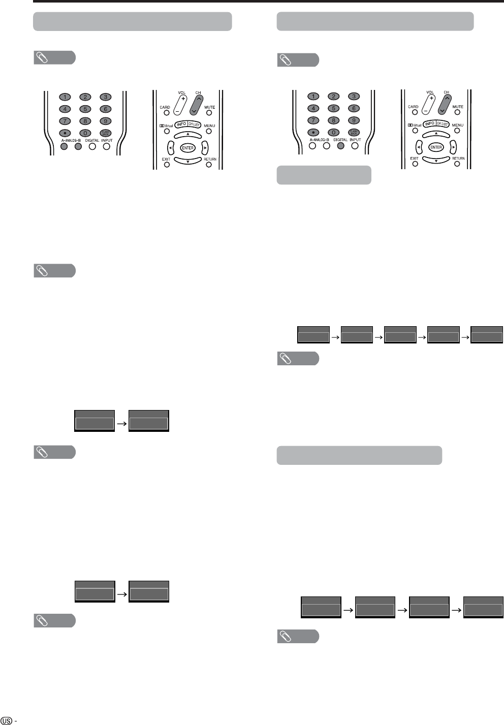
Changing channels - Analog-TV
You can change channels in several ways.
NOTE
• While watching a broad cast, press A-ANALOG-B to view
the image received from the other tuner.
Method 1
Using CHr/s on the remote control unit or on the
display.
Method 2
1. Press FLASHBACK to switch to the previously tuned
channel.
2. Press FLASHBACK again to switch back to the
currently tuned channel.
NOTE
•FLASHBACK will not work if no channel has been
changed after TV is turned on.
Method 3
Using remote control buttons (0-9 andENTER) to select
up to 125 channels for VHF/UHF/CATV.
To select a 1 or 2-digit channel number
(e. g., Channel 5):
Press 5s ENTER
NOTE
• Complete the above steps within a few seconds.
• When selecting a 1-digit channel number, it is not
necessary to press 0 before the number.
• When you enter 0-9 only, channel selection will be made
if there is no operation for 2 seconds.
• •(dot) can be used instead of ENTER.
To select a 3-digit channel number
(e. g., Channel 69):
Press 6s9
NOTE
• Complete the above steps within a few seconds.
• When you enter 0-9 only, channel selection will be made
if there is no operation for 2 seconds.
• If you push “0” by itself, nothing will happen
• •(dot) can be used instead of ENTER.
Changing channels - Digital-TV
You can change channels in several ways.
NOTE
• While watching a broad cast, press DIGITAL.
Digital - Air/Cable
Method 1
When you press CHr/sor FLASHBACK, repeat the
same steps for Analog-TV.
Method 2
1. Using remote control buttons (0-9, •(dot) and
ENTER) to select the channels including a decimal
point.
To select a 3-digit channel number
(e. g., Channel 22.1):
Press 2 s2s•(dot) s1s ENTER
NOTE
• Complete the above steps within a few seconds.
• When you enter 0-9 and •(dot), channel selection will be
made if there is no operation for 2 seconds.
• •(dot) can be used instead of ENTER.
• When entering a 2-part channel number, pushing •(dot)
after the second part of the number has the same function
as ENTER.
Digital - Cable (One-part Number)
Method 1
When you press CHr/sor FLASHBACK, repeat the
same steps for Analog-TV.
Method 2
Using remote control buttons (0-9 and ENTER) to select
the channels including a decimal point.
To select a 5-digit channel number
(e. g., Channel 310):
Press 3s1s0sENTER
NOTE
• Complete the above steps within a few seconds.
• When you enter 0-9 only, channel selection will be made
if there is no operation for 2 seconds.
• •(dot) can be used instead of ENTER.
• Digital Cable Channels are shown by a number with a
maximum of 5 digits.
5
ANALOG-A Air
5
ANALOG-A Air
69
ANALOG-A Air
6
ANALOG-A Air
22.
Digital Air
22.122.1
Digital Air
22
Digital Air
2
Digital Air
310
Digital Cable
310
Digital Cable
31
Digital Cable
3
Digital Cable
23
Watching TV
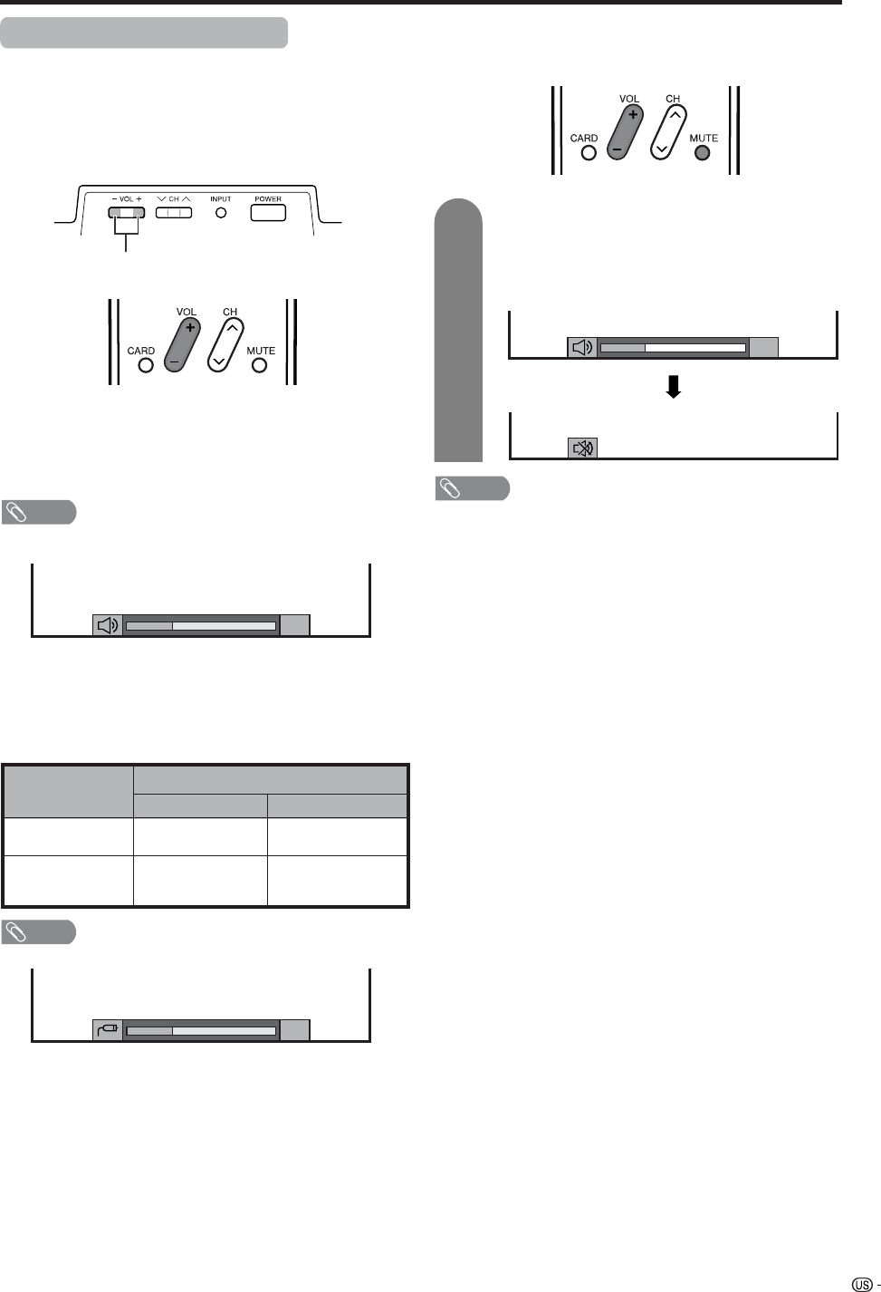
Volume adjustment
Mute
• To increase the volume, press VOL kk
kk
k.
• To decrease the volume, press VOL ll
ll
l.
NOTE
Output device
Variable sound
Output Select
VariableFixed
Variable sound
Constant as
specified
Mute
•VOL l/kon the Display operates the same as VOL k/l
on the remote control unit.
Audio status
* When “Output Select” is set to “Variable”, the indicator on
the screen changes as shown below.
Speaker
MONITOR OUT
Changing volume/sound
■ Changing the volume
You can change the volume on the Display or on the
remote control unit.
■ Using VOL kk
kk
k/ll
ll
l
NOTE
• See page XX for details on the output select function.
■ Using MUTE on the remote control unit
Mutes the current sound output.
Press MUTE.
•“M” has been displayed on the screen for 30
minutes, and the sound is silenced.
NOTE
• Within 30 minutes of pressing MUTE, mute can be
canceled by using one of the methods below.
• Mute will cancel if you press VOL l/k or MUTE.
•Mute will be canceled after 30 minutes have passed.
However, the TV will not suddenly output a loud sound as
the volume level is set to 0 automatically.
Display
VOL l/k
20
20
20
1
24
Watching TV
NOTE
• MTS only operates while in TV mode.
You can change MTS as
shown below to match
the television broadcast
signal.
STEREOkSAP mode MONO mode
Examples: when receiving MTS and SAP
STEREO mode MAINkSAP mode
Setting MTS/SAP stereo mode
The TV has a feature that allows reception of sound
other than the main audio for the program. This feature
is called Multi-channel Television Sound (MTS). The
TV with MTS can receive mono sound, stereo sound
and Secondary Audio Programs (SAP). The SAP
feature allows a TV station to broadcast other
information, which could be audio in another language
or something completely different like weather
information.
You can enjoy Hi-Fi stereo sound or SAP
broadcasts where available.
•Stereo broadcasts
View programs like live sporting events, shows and
concerts in dynamic stereo sound.
•SAP broadcasts
Receive TV broadcasts in either MAIN or SAP sound.
MAIN sound: The normal program soundtrack (either in
mono or stereo).
SAP sound: Listen to second language, supplementary
commentary and other information. (SAP is mono sound.)
If stereo sound is difficult to hear.
• Obtain a clearer sound by manually switching to fixed
mono-sound mode.
2
ANALOG-A Air
Audio : MONO
2
ANALOG-A Air
Audio : ST(SAP)
2
ANALOG-A Air
Audio : SAP(ST)
2
ANALOG-A Air
Audio : MONO
2
ANALOG-A Air
Audio : MONO
2
ANALOG-A Air
Audio : STEREO
2
ANALOG-A Air
Audio : MAIN
2
ANALOG-A Air
Audio : SAP
25
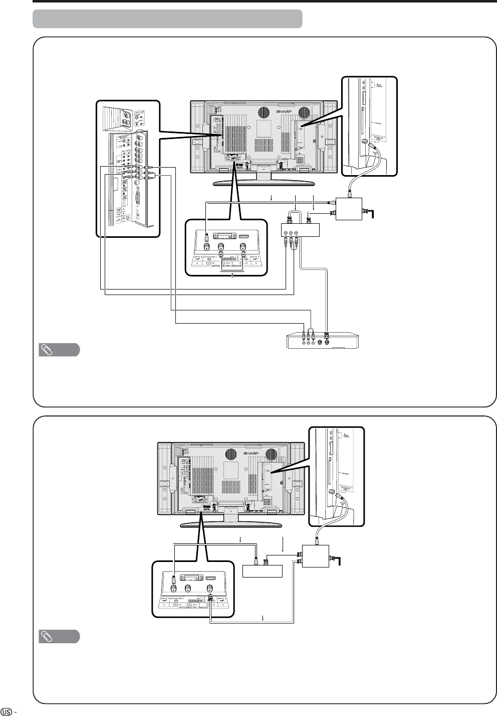
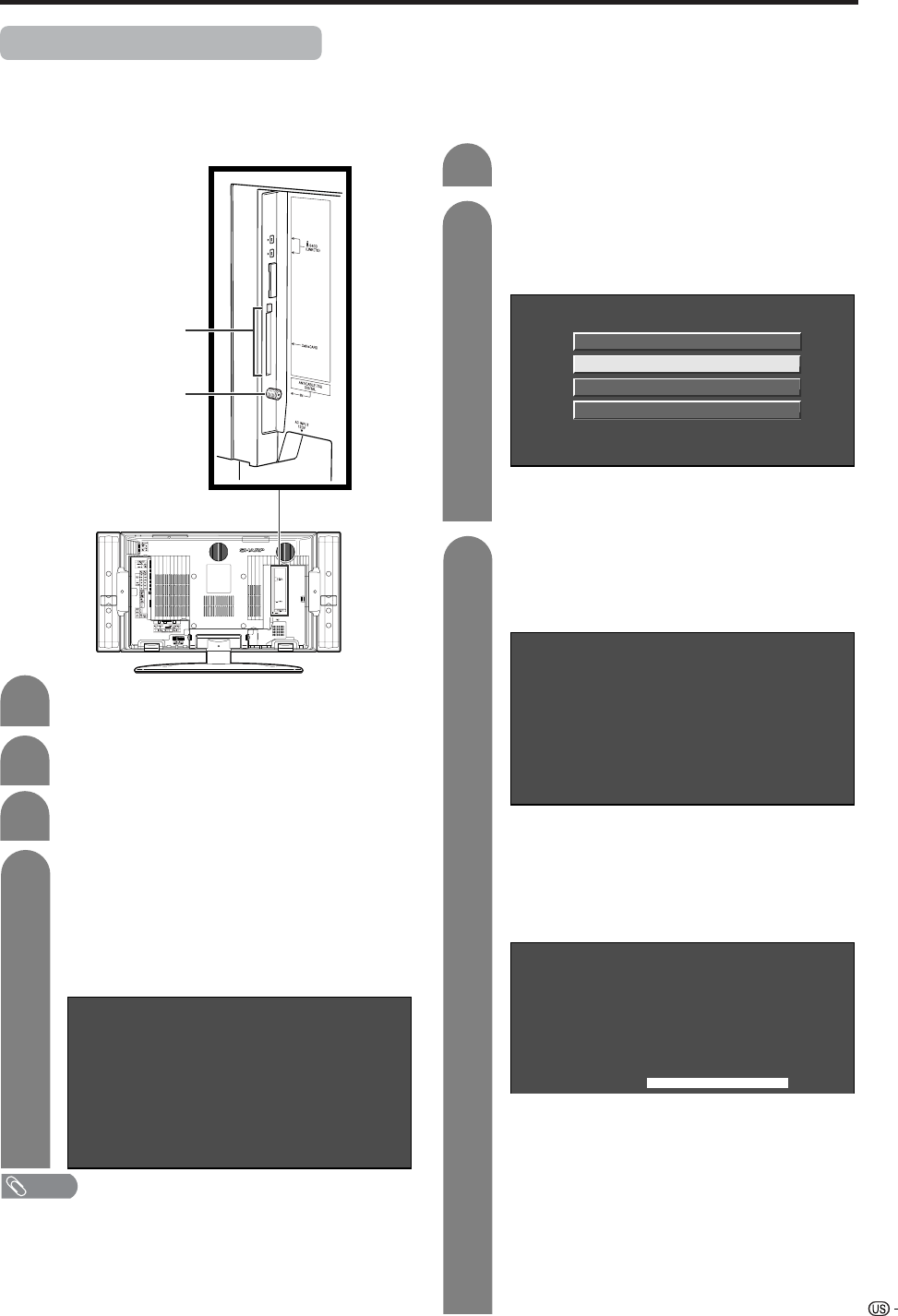
Connecting Digital Cable Module
Digital Cable Module is called CableCARD. By attaching the CableCARD, you can receive various digital services
provided by your Cable Company. To obtain and use a CableCARD you need to first submit an application.
Please contact your cable company to discuss receiving and application. Digital Cable allow you to tune digital
and high-definition cable channels through the cable antenna. This module is called the CableCARD.
Watching TV
Connect the cable antenna to ANT/CABLE
75 q DIGITAL IN.
2
Insert the CableCARD (upper side facing left)
into the CableCARD slot.
• A message will appear on the screen. (It might
take a couple of minutes before the message
appears.) Call the number on the screen and
tell the operator the CableCARD ID and Host
ID numbers displayed on the screen.
4
2
Press c/d to select “Digital Setup”, a/b to
select “CableCARD MENU”, a/b to select
“Pairing Information”, and then press
ENTER.
3
Press MENU and the MENU screen appears.
1
A message will appear on the screen. Call
the number on the screen and tell the
operator the CableCARD ID and Host ID
numbers displayed on the screen.
Paring Information
Diagnostic Screen
ECM
Conditional Access
CableCARD Dialog
CableCARD(tm) Pairing Status
In order to start cable service
for this device, please contact
your cable provider
1-888-555-2222
CableCARD(tm) ID:
7-561-034-449-009
Host ID:
0-100-331-784-018
• If there is a white triangle at the right side of
the screen, the screen is not showing the entire
message. Press a/b on your remote control
to display the rest of the message.
• When there is a “LINK” button on the screen,
there is a link to the next page. Press ENTER
to go to the next page.
CableCARD slot
ANT/CABLE 75 q
DIGITAL
NOTE
• Do not insert a PCMCIA card into the CableCARD slot.
• Please do not pull the AC cord out while the CableCARD
is inserted.
■If the above procedure does not work,
please follow the following steps instead.
CableCARD(tm) Pairing Status
In order to start cable service
for this device, please contact
your cable provider
1-888-555-2222
CableCARD™ ID:
7-561-034-449-009
Host ID:
0-100-331-784-018
• The words “Pairing Information” may be
replaced by a different expression depending
of the manufacturer of the CableCARD.
CableCARD(tm)
Diagnostic Information
Power: ON
In band: O.K.
Out of band: O.K.
Video: O.K.
Audio: O.K.
LINK
Turn on the POWER.
1
Select “Cable” in “Antenna Setup”. (See
page 30)
3
Removing CableCARD
• Turn on the POWER.
• Check that the CableCARD upgrade screen is
not displayed. If it is displayed, wait until it
disappears.
• Remove the cableCARD.
Disconnecting the cable antenna
• Turn on the POWER.
• Check that the CableCARD upgrade screen is
not displayed. If it is displayed, wait until it
disappears.
• Disconnect the cable antenna.
26
Basic adjustment settings
AV input mode menu items
List of AV menu items to help you with
operations
OPC ................................................ Page 33
Backlight ........................................ Page 32
Contrast ......................................... Page 32
Brightness ..................................... Page 32
Color ............................................... Page 32
Tint ................................................. Page 32
Sharpness...................................... Page 32
Advanced
C.M.S. ................................... Page 33
Color Temp. ......................... Page 33
Black .................................... Page 34
3D-Y/C .................................. Page 34
Monochrome ....................... Page 35
Film Mode ............................ Page 35
I/P Setting ............................ Page 35
Picture
No Signal Off ................................. Page 37
No Operation Off ........................... Page 37
EZ Setup ........................................ Page 27
CH Setup .................................Pages 28-29
Antenna Setup-DIGITAL ............... Page 31
Speaker Setup ............................... Page 64
Input Label ..................................... Page 64
Parental CTRL ........................ Pages 79-83
Position .......................................... Page 62
Picture Flip .................................... Page 64
Language ....................................... Page 30
Treble.............................................. Page 36
Bass ............................................... Page 36
Balance .......................................... Page 36
Dolby Virtual .................................. Page 36
Audio Only ..................................... Page 70
Digital Noise Reduction ............... Page 70
HDMI Setup .................................... Page 54
Input Select.................................... Page 66
Output Select................................. Page 71
Quick Shoot ................................... Page 71
Center Channel Input ................... Page 84
Caption Setup........................... Page 73-75
Title Display Type .......................... Page 72
Audio
Power Control
Setup
Option
*PC input mode menu items
List of PC menu items to help you with
operations
*When INPUT4 is set to PC.
OPC ................................................ Page 33
Backlight ........................................ Page 32
Contrast ......................................... Page 32
Brightness ..................................... Page 32
Red ................................................. Page 32
Green .............................................. Page 32
Blue ................................................ Page 32
Advanced
C.M.S. ................................... Page 33
Picture
Audio
Treble.............................................. Page 36
Bass ............................................... Page 36
Balance .......................................... Page 36
Dolby Virtual .................................. Page 36
CableCARD Menu ......................... Page 25
Video Setup ................................... Page 38
Audio Setup ................................... Page 39
i.LINK Setup................................... Page 58
Digital Setup
27
Basic adjustment settings
Power Management ...................... Page 37
Speaker Setup ............................... Page 64
Input Signal ................................... Page 70
Auto Sync. ..................................... Page 65
Input Label ..................................... Page 67
Fine Sync. ...................................... Page 65
Picture Flip .................................... Page 64
Language ....................................... Page 30
Power Control
Setup
Option
Audio Only ..................................... Page 70
Input Select.................................... Page 66
Output Select................................. Page 71
Quick Shoot ................................... Page 71
Center Channel Input ................... Page 84
EZ setup
You can run EZ Setup again, even after setting up the
preset channels.
Language setting
Select from among 3 languages: English, French and
Spanish.
Press MENU and the MENU screen displays.
Press c/d to select “Setup”.
1
2
Press a/b to select “EZ Setup”, and then
press ENTER.
• If you already set the Secret No., go to step 4. If
not, skip to step 5.
Input the 4-digit secret number by using 0 – 9.
3
MENU [Setup ... EZ Setup]
Setup Option
Secret No. ––––
4
5
Press a/b to select the desired language
listed on the screen, and then press ENTER.
Language
Air/Cable
CH Search English
Español
Français
i.LINK Setup................................... Page 25
Digital Setup
28
Basic adjustment settings
Antenna setting
Make sure what kind of connection is made with your TV when
selecting “Air” or “Cable” for ANALOG-A, B and DIGITAL.
6
7
Searching TV channels
Press c/d to select “Air” or “Cable” for
ANALOG-A, then press a/b to move down.
Press c/d to select “Air” or “Cable” for
ANALOG-B. Press c/d to select “Cable
(STD)”, “Cable (HRC)” or “Cable (IRC)” for
DIGITAL (cable).
Press ENTER to enter the setting.
• This operation makes the System search for both
ANALOG-A and B.
• There are 3 kinds of CATV system, including
Standard, HRC and IRC. Select the one matches
to your TV. Select Auto when you do not know
which one to select.
Channel search
Channel auto search makes the System look for all
channels viewable in the set area.
MENU [Setup ... EZ Setup ... CH Search]
ANALOG-A
[ ]25Air [ ]20Found
MENU [Setup ... EZ Setup ... CH Search]
ANALOG-B
[ ]2Cable [ ]20Found
Example
NOTE
• If no channel is found, make sure what kind of connection is
made with your TV and try EZ setup again.
• Make sure what kind of connection is made with your TV when
selecting “Air” or “Cable” for both ANALOG-A and B.
Press c/d to select “Yes” for ANALOG-A, then
press a/b to move down.
Press c/d to select “Yes” for ANALOG-B, then
press a/b to move down.
Press c/d to select “Cable (STD)”, “Cable
(HRC)” or “Cable (IRC)” for DIGITAL (cable).
ANALOG-A
Yes
ANALOG-B
No
Yes No
DIGITAL Yes No
Search Start
Language
Air/Cable
CH Search
MENU [Setup ... EZ Setup ... CH Search]
DIGITAL
[ ]25Air [ ]20Found
Channel setup
If initial setup does not memorize all the channels in
your region, follow the instructions below to manually
memorize the channels.
Press MENU and the MENU screen displays.
Press c/d to select “Setup”.
1
2
3
Press a/b to select “CH Setup”, and then
press ENTER.
• If you already set the Secret No., input the 4-
digit secret number here. See page XX for
setting a secret number.
Antenna setting
Press c/d to select “Air” or “Cable” for
ANALOG-A, then press a/b to move down.
Press c/d to select “Air” or “Cable” for
ANALOG-B.
Press c/d to select “Air” or “Cable” for
DIGITAL, then press a/b to move down.
Press ENTER to enter the setting.
ANALOG-A
ANALOG-B
Air
Cable (Auto)
DIGITAL Air
Air/Cable
CH Search
CH Memory
Example
5
4
Press a/b to select “Air/Cable”, and then
press ENTER.
Air/Cable
CH Search
ANALOG-A
ANALOG-B
Air
DIGITAL Air
Air
CH Memory
29
Basic adjustment settings
NOTE
• Make sure what kind of connection is made with your TV
when selecting “Air” or “Cable” for both ANALOG-A, B
and DIGITAL.
• There are 3 kinds of CATV system, including Standard,
HRC and IRC. Select the one matches to your TV. Select
Auto when you do not know which one to select.
Channel search
Channel auto search makes the System look for all
channels viewable in the set area.
Press MENU and the MENU screen displays.
Press c/d to select “Setup”.
1
2
3
Press a/b to select “CH Search”, and then
press ENTER.
Air/Cable
CH Search
ANALOG-A
Yes
ANALOG-B
No
Yes No
DIGITAL (Air)
Yes No
Search Start
CH Memory
Press c/d to select “Yes” for ANALOG-A,
then press a/b to move down.
Press c/d to select “Yes” for ANALOG-B,
then press a/b to move down.
Press c/d to select “Yes” for DIGITAL (Air/
Cable), and press a/b to move down.
Select “Search Start”, and then press
ENTER.
4
5
NOTE
• Make sure what kind of connection is made with your TV.
Press a/b to select “CH Setup”, and then
press ENTER.
• If you already set the Secret No., input the 4-
digit secret number here. See page 66 for
setting a secret number.
Example: CH Search
MENU [Setup ... EZ Setup ... CH Search]
ANALOG-A
[ ]25Air [ ]20Found
MENU [Setup ... EZ Setup ... CH Search]
ANALOG-B
[ ]2Cable [ ]20Found
MENU [Setup ... EZ Setup ... CH Search]
DIGITAL
[ ]25Air [ ]20Found
Channel memory setting
Press MENU and the MENU screen displays.
Press c/d to select “Setup”.
MENU
[Setup ... CH Setup]
Air/Cable
CH Search
CH Memory
CH
Skip On Off
Antenna ANALOG
Air
1
2
3
4
Press a/b to select “CH Setup”, and then
press ENTER.
• If you already set the Secret No., input the 4-
digit secret number here. See page 66 for
setting a secret number.
Press c/d to select ANALOG-A, B or
DIGITAL.
5
6
Press a/b to select “CH Memory-ANALOG”
or “CH Memory-DIGITAL”, and then press
ENTER.Example
Press a/b and press c/d to select the
channel you want to skip or not.
ANTENNA-A
ANTENNA-B
DIGITAL
CableCARD
Skip On Off
DIGITAL (Air)
Yes No
Air [ 32] 2 69
Press a/b to select “Skip”, and press c/d
to select “On” or “Off”.
• On: Skips channels. (Channel selection disabled using
CHaa
aa
a/bb
bb
b.)
• Off: Does not skip channels. (Channel selection enabled
using CHaa
aa
a/bb
bb
b.)
7
NOTE
• Make sure what kind of connection is made with your TV.
30
Basic adjustment settings
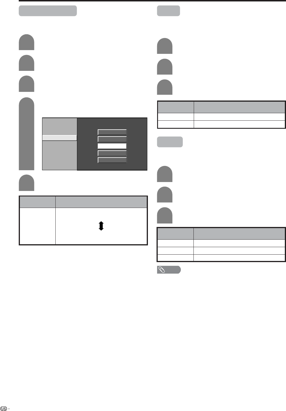
Favorite channel setting
This function allows you to program 4 favorite channels,
in 4 different categories. By setting the favorite
channels in advance, you can select your favorite
channels easily.
Press EDIT.
Press a/b to select “Register”, and then
press ENTER.
2
3
Press EDIT and the favorite channel screen
displays.
Press a/b to select “1 Data Clear”, and then
press ENTER.
Press a/b/c/d to select the position in the
area, and then press ENTER to register.
Press a/b/c/d to select the channel you
want to delete, and then press ENTER.
1
2
3
ANALOG-A
3
ABCD
ANALOG-A
3ANALOG-A
18
ANALOG-A
125
DIGITAL
100
ANALOG-B
33 ANALOG-B
51
ABCD
Register
All Data Clear
1 Data Clear
Delete favorite channel
ANALOG-A
3
ANALOG-A
125
ANALOG-B
33 ANALOG-B
51
ABCD
DIGITAL
100
Yes No
NOTE
• You can delete all the favorite channels by selecting “All
Data Clear” in step 2 in Delete favorite channel.
Select the channel you want to register as a
favorite channel.
1
4
4
Press c/d to select “Yes”, and then press
ENTER.
Language setting
You can also select a language from the Setup menu.
Select from among 3 languages: English, French and
Spanish.
3
Press MENU and the MENU screen displays.
1
2
Press c/d to select “Setup”.
Press a/b to select “Language”, and then
press ENTER.
4
English
Español
Français
Press a/b to select the desired language
listed on the screen, and then press ENTER.
31
Basic adjustment settings
Antenna Setup - DIGITAL
This function allows you to set the connected digital
antenna.
1
2
Press MENU and the MENU screen displays.
Press c/d to select “Setup”.
Press a/b to select “Antenna Setup -
DIGITAL”, and then press ENTER.
• If you already set the Secret No., input the 4-
digit secret number here. See page 77 for
setting a secret number.
4
3
Press a/b to select “Ant. Power Setup”, and
press ENTER.
5
When the Lebel indicator is max, press
ENTER.
Press a/b to select “Frequency Setup”, and
then press ENTER.
6
Press a/b to select “Signal Test”, and input
a channnel number using 0-9.
Ant. Power Setup
Frequency Setup
Signal Strength
Current
Signal Test
Max00
Ant. Power Setup
Frequency Setup
Signal Strength
Current
CH
Signal Test
Max0
12
0
32
Adjustments items for PC source
Basic adjustment settings
cbutton
The screen dims
For less contrast
For less brightness
For less color
intensity
Skin tones become
purplish
For less sharpness
Selected item
Backlight
Contrast
Brightness
Color
Tint
Sharpness
Adjustments items for AV source
MENU [Picture]
Picture Audio
Contrast
OPC
Brightness
Reset
[+30]
[ 0]
0
–30
+40
+30
Backlight [ +8] –8 +8
Off On
Red
Green
Blue
Advanced
[ 0]
[ 0]
[ 0]
–30
–30
–30
+30
+30
+30
On : Display
MENU [Picture]
Picture Audio
Contrast
OPC
Brightness
Color
Tint
Sharpness
Advanced
Reset
[+30]
[ 0]
[ 0]
[ 0]
[ 0]
0
–30
–30
–30
–10
+40
+30
+30
+30
+10
Backlight [ +8] –8 +8
Off On On : Display
NOTE
• Select “Advanced” and then press ENTER to set “C.M.S-
Hue”, “C.M.S-Saturation”, “C.M.S-Value”, “Color Temp.”,
“Black”, “3D-Y/C”, “Monochrome”, “Film Mode” or “I/P
Setting”. See pages 33 to 35.
dbutton
The screen brightens
For more contrast
For more brightness
For more color
intensity
Skin tones become
greenish
For more sharpness
cbutton
The screen dims
For less contrast
For less brightness
For weaker red
For weaker green
For weaker blue
Selected item
Backlight
Contrast
Brightness
Red
Green
Blue
dbutton
The screen brightens
For more contrast
For more brightness
For stronger red
For stronger green
For stronger blue
Picture adjustments
Adjusts the picture to your preference with the following
picture settings.
Press MENU and the MENU screen displays.
1
2
3
4
Press a/b to select a specific adjustment
item.
Press c/d to adjust the item to your desired
position.
Press c/d to select “Picture”.
NOTE
• For resetting all adjustment items to factory preset values,
press a/b to select “Reset”, press ENTER, press c/d
to select “Yes”, and then press ENTER.
NOTE
• Select “Advanced” and then press ENTER to set “C.M.S-
Hue”, “C.M.S-Saturation” and “C.M.S-Value”.
33
OPC setting
Automatically adjusts the brightness of the screen.
Press c/d to select “Picture”.
2
Press MENU and the MENU screen displays.
1
Press a/b to select “OPC”.
Press c/d to select “On” or “On: Display”.
3
4
Basic adjustment settings
Description
The brightness is fixed at the value set in
“Backlight” (see page XX).
Automatically adjusts
Displays the OPC effect on the screen while
adjusting the brightness of the screen.
Selected item
Off
On
On: Display
NOTE
• When set to “On”, the OPC senses the surrounding light
and automatically adjusts the backlight brightness. Make
sure no object obstructs the OPC sensor, which could
affect its ability to sense surrounding light.
• When set to “On: Display”, OPC effect displays on the
screen while OPC is adjusting the screen brightness.
Contrast
OPC
Brightness
Color
Tint
Sharpness
Advanced
Reset
[+30]
[ 0]
[ 0]
[ 0]
[ 0]
0
–30
–30
–30
–10
+40
+30
+30
+30
+10
Backlight [ +8] –8 +8
Off On On : Display
C.M.S. (Color Management System)
Color tone is managed using the six-color adjustment
setting.
Press MENU and the MENU screen displays.
1
2
Press c/d to select “Picture”.
3
Press a/b to select “Advanced”, and then
press ENTER.
4
Press a/b to select “C.M.S-Hue”, and then
press ENTER.
5
Press a/b to select a specific adjustment
item. Press c/d to adjust the item to your
desired position.
C. M. S.-Hue
R
Y
G
C
B
M
Reset
[ 0]
[ 0]
[ 0]
[ 0]
–30
–30
–30
+30
–30 +30
+30
+30
[ 0] –30 +30
[ 0] –30 +30
Changing reds
closer to
magenta or yellow.
C. M. S.-Saturation
C. M. S.-Value
NOTE
• For resetting all adjustment items to the factory preset
values, press a/b to select “Reset”, and then press
ENTER.
• You can select “C.M.S-Saturation” or “C.M.S-
Value” here instead of selecting “C.M.S-Hue”.
Description
This is a standard to adjust the color either
more reddish or more bluish in tone.
Increases or decreases the saturation of a
selected color.
A higher value makes the image brighter.
A lower value makes the image darker.
Selected item
C.M.S-Hue
C.M.S-
Saturation
C.M.S-
Value
34
Basic adjustment settings
Color temperature
For a better white balance, use color temperature
correction.
4
5
Press a/b to select “Color Temp.”, and then
press ENTER.
Description
White with Bluish tone
White with Reddish tone
Selected item
High
Mid-High
Middle
Mid-Low
Low
Press MENU and the MENU screen displays.
1
2
Press c/d to select “Picture”.
3
Press a/b to select “Advanced”, and then
press ENTER.
C. M. S-Hue
C. M. S-Saturation
C. M. S-Value
Color Temp.
Black
3D-Y/C
Monochrome
Film Mode
I/P Setting
High
Mid-High
Middle
Mid-Low
Low
Black
For easier viewing, change the viewing depth by
selecting a level for automatically adjusting the dark
portion of an image.
Press a/b to select the desired level, and
then press ENTER.
Press a/b to select “Black”, and then press
ENTER.
Press c/d to select “On”, and then press
ENTER.
Repeat steps 1 to 3 in Color temperature.
1
2
3
Description
No adjustment
For high detail in black portions
Selected item
Off
On
3D-Y/C
Provides high quality images with minimal dot crawl
and cross color noise.
Description
Normal adjustment
For movie image
For still image
Selected item
Standard
Fast
Slow
Press a/b to select “3D-Y/C”, and then
press ENTER.
Repeat steps 1 to 3 in Color temperature.
1
2
3
Press a/b to select the desired level, and
then press ENTER.
NOTE
• 3D-Y/C is not available for S-video, Component, DVI,
HDMI, CARD, DIGITAL-TV or i.Link inputs.
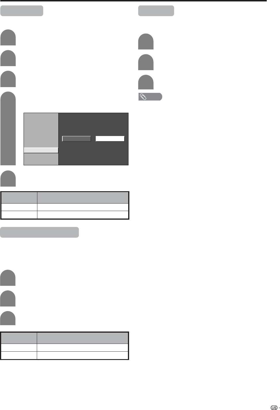
35
Basic adjustment settings
Monochrome
For viewing a video in monochrome.
Description
Normal color
For viewing in monochrome
Selected item
Off
On
Press a/b to select “Monochrome”, and
then press ENTER.
4
Press c/d to select “On”, and then press
ENTER.
5
Press MENU and the MENU screen displays.
1
2
Press c/d to select “Picture”.
3
Press a/b to select “Advanced”, and then
press ENTER.
C. M. S-Hue
C. M. S-Saturation
C. M. S-Value
Color Temp.
Black
3D-Y/C
Monochrome
Film Mode
I/P Setting
On Off
Film mode (3:2 pull-down)
Automatically detects a film-based source (originally
encoded at 24 frames/second), analyzes it then
recreates each still film frame for high-definition picture
quality.
Description
Normal viewing mode
Detects, analyzes, converts film source
Selected item
Off
On
Press a/b to select “Film Mode”, and then
press ENTER.
Repeat steps 1 to 3 in Monochrome.
1
2
3
Press c/d to select “On”, and then press
ENTER.
I/P Setting
Adjusting the image and input signal can give you a
more beautiful picture.
Press a/b to select “I/P Setting”, and then
press ENTER.
Press c/d to select “Interlace” or
“Progressive”, and then press ENTER.
Repeat steps 1 to 3 in Monochrome.
1
2
3
NOTE
• I/P Setting is set to Progressive when Film Mode is “On”.
• “I/P Setting” is not selectable when channel display shows
an input resolution of 480P, 720P or 1080I.
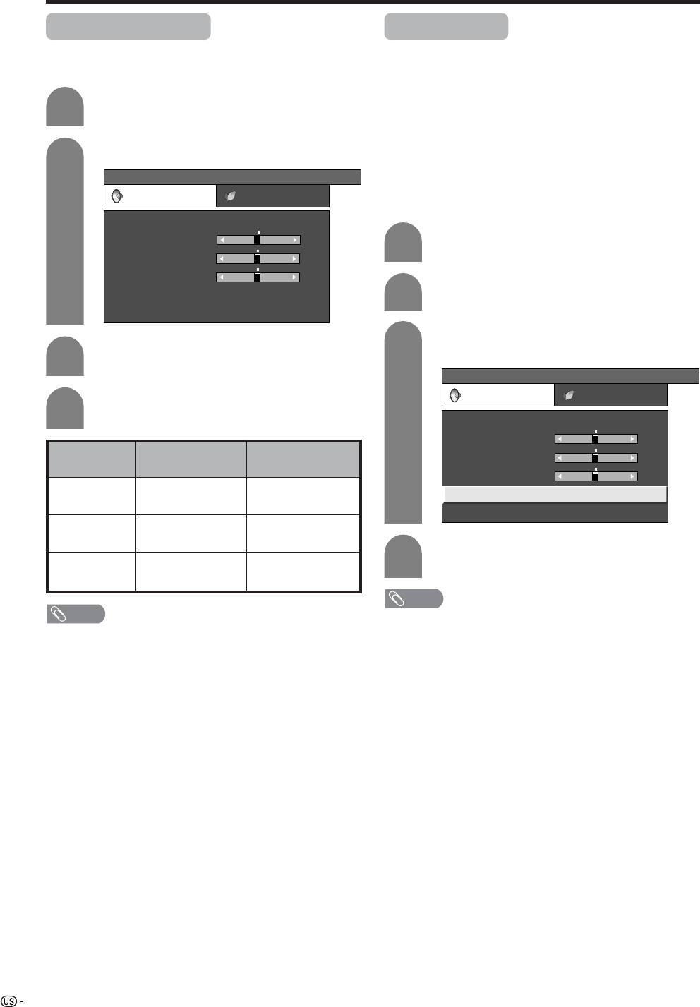
36
Basic adjustment settings
Sound adjustment
You can adjust the sound quality to your preference
with the following settings.
Press c/d to select “Audio”.
Press a/b to select a specific adjustment
item.
Press c/d to adjust the item to your desired
position.
2
3
4
cbutton
For weaker treble
For weaker bass
Decrease audio from
the right speaker
Selected item
Treble
Bass
Balance
dbutton
For stronger treble
For stronger bass
Decrease audio from
the left speaker
Press MENU and the MENU screen displays.
1
MENU
[Audio]
Audio Power Control
Treble
Bass
Balance
Dolby Virtual
Reset
[Off]
[0]
[0]
–15
L
+15
[0] –15 +15
R
NOTE
• Audio menu is grayed out when Output Select is set to
“Variable” or when headphones are in use.
• Balance and Audio Quality Control are grayed out when
Dolby Virtual is set to “On”.
• For resetting all adjustment items to factory preset values,
press a/b to select “Reset”, press ENTER, press c/d
to select “Yes”, and then press ENTER.
Press c/d to select “Audio”.
Press a/b to select “Dolby Virtual”, and
then press ENTER.
Press c/d to select “On”, and then press
ENTER.
2
3
4
Press MENU and the MENU screen displays.
1
Dolby virtual
You can enjoy the SURROUND 2ch stereo with Dolby
Pro Logic II technology.
VIRTUAL DOLBY DIGITAL is a technology certified by
Dolby Laboratories that creates a virtualized surround
sound experience from two speakers using Dolby Pro
Logic or Dolby Pro Logic II.
VIRTUAL DOLBY DIGITAL retains all the original
multichannel audio information and provides the
listener with the sensation of being surrounded by
additional speakers.
MENU
[Audio ... Dolby Virtual]
Audio Power Control
Treble
Bass
Balance
Dolby Virtual
Reset
[Off]
[0]
[0]
–15
L
+15
[0] –15 +15
R
NOTE
• Audio menu is grayed out when Output Select is set to
“Variable” or when headphones are in use.
• Balance and Audio Quality Control are grayed out when
Dolby Virtual is set to “On”.
• For some discs, setup may be required on your DVD. In
this case, please refer to the operation manual of your
DVD player.
• You may not get the Dolby Virtual Surround effect if you
adjust “Treble” or “Bass” setting.
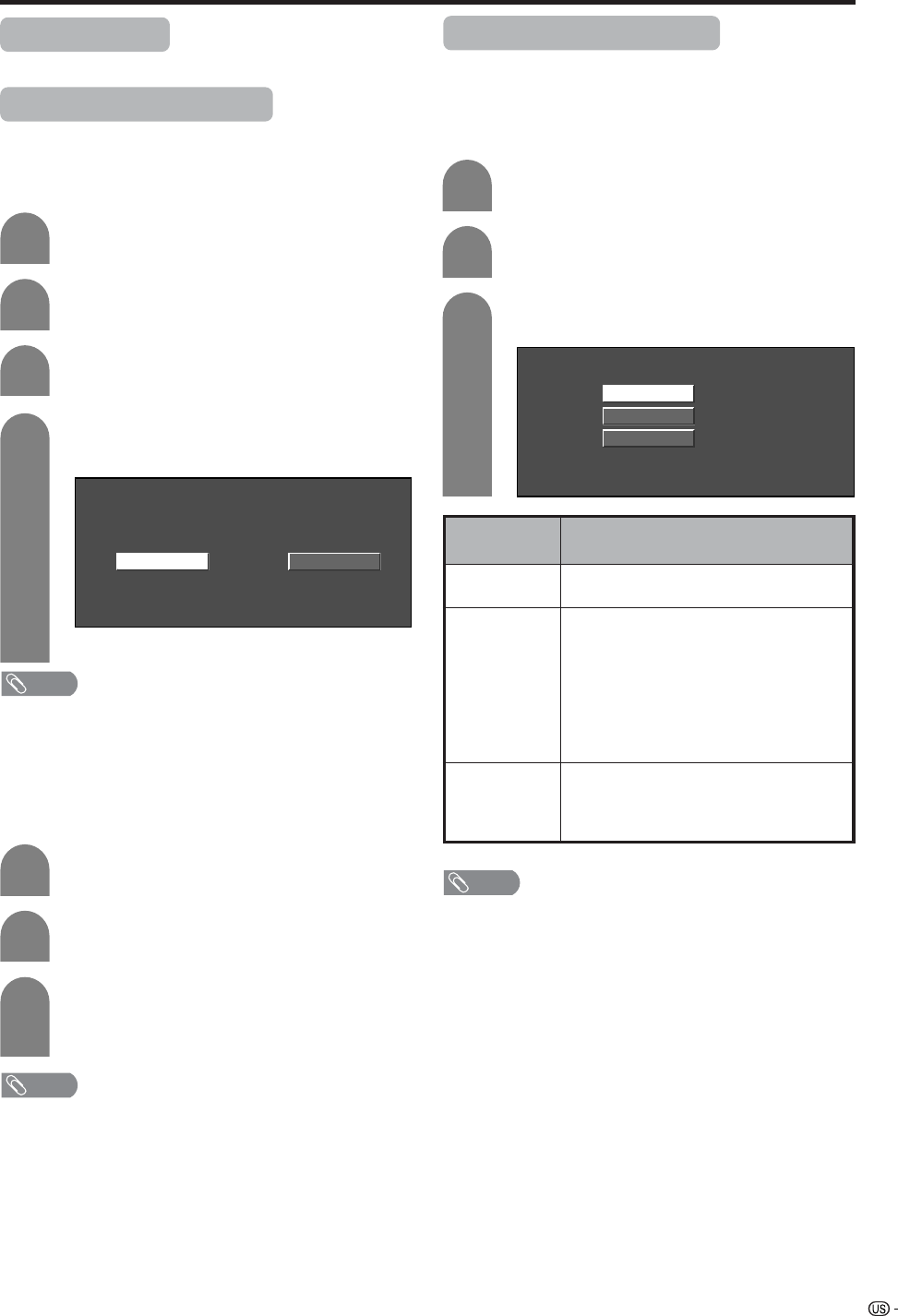
37
Basic adjustment settings
No signal off
When set to “Enable”, the power will automatically shut
down if no signal inputs for 15 minutes.
Press a/b to select “No Signal Off”, and
then press ENTER.
Press c/d to select “Enable”, and then
press ENTER.
3
4
• Five minutes before the power shuts down,
remaining time displays every minute.
NOTE
• “Disable” is factory preset value.
• When a TV program finishes, this function may not operate.
Press c/d to select “Power Control”.
Press MENU and the MENU screen displays.
No operation off
When set to “Enable”, the power will automatically shut
down if there is no operation for 3 hours.
Press a/b to select “No Operation Off”, and
then press ENTER.
Press c/d to select “Enable”, and then
press ENTER.
• Five minutes before the power shuts down,
remaining time displays every minute.
NOTE
• “Disable” is factory preset value.
Repeat steps 1 and 2 in No signal off.
2
1
DisableEnable
3
2
1
Power control
Power control setting allows you to save energy.
Power control for AV source
Power control for PC source
Power control setting allows you to save energy.
Power management
When set, the power will automatically shut down.
Press a/b to select “Power Management”,
and then press ENTER.
Press a/b to select “Mode1” or “Mode2”,
and then press ENTER.
Description
• No power management
• Factory preset value.
• If no signal inputs for 8 minutes, the power
shuts down.
• Even if you start using the PC and the signal
inputs again, the TV stays off.
• The TV turns on again by pressing TV
POWER on the remote control unit. (See
page 20).
• Press POWER on the display will have the
same result.
• If no signal inputs for 8 seconds, the power
shuts down.
• When you start using the PC and the signal
inputs again, the TV turns on.
Selected item
Off
Mode1
Mode2
Repeat steps 1 and 2 in No signal off.
3
2
1
Off
Mode1
Mode2
NOTE
• When using a digital PC and setting “Mode2” in Power
management, the power may not turn back on
automatically even if the signal inputs again.
• If you turn off the power by disconnecting AC cord when
setting “Mode2” in power management, the TV may not
function properly after turning the power on again. In such
case, press TV POWER on the remote control unit.
• Press POWER on the display will have the same result.
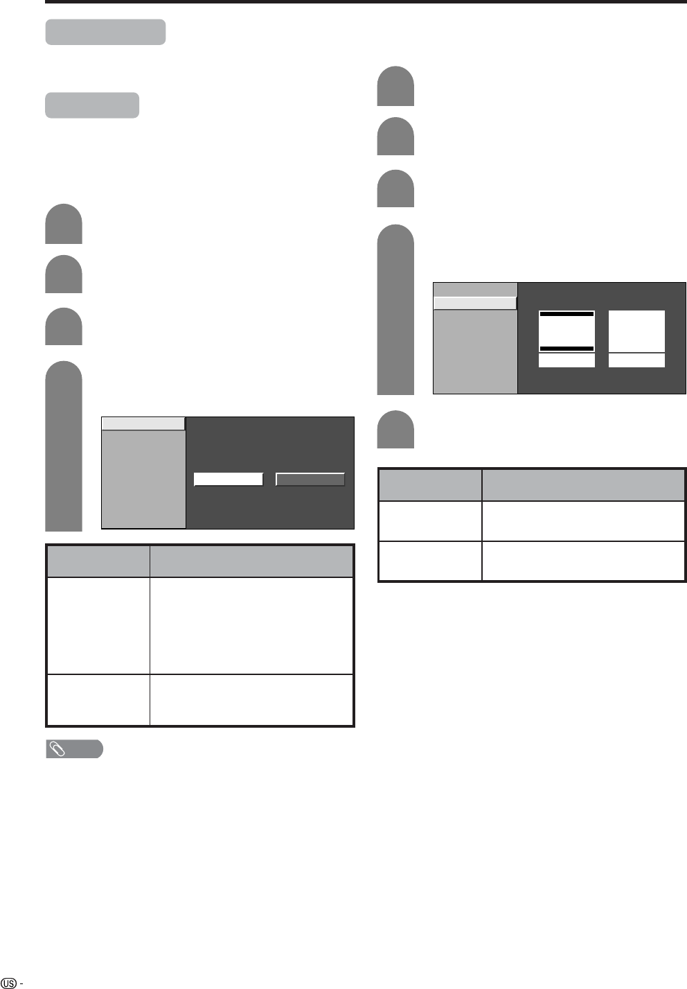
38
Basic adjustment settings (DIGITAL)
Digital Setup
This setting allows you to set the image of Digital
broadcasting.
Video Setup
You can adjust the settings for Digital image.
1
2
3
Press MENU and the MENU screen displays.
Press c/d to select “Digital Setup”.
Screen Size
Set the format of image of Digital broadcasting.
Press a/b to select “Video Setup”, and then
press ENTER.
4
Press a/b to select “Screen Size”, and then
press ENTER.
NOTE
• "Manual" is factory preset value.
REC Picture Size
Select the screen size to record on 16:9 video.
Press MENU and the MENU screen displays.
Press c/d to select “Digital Setup”.
Press a/b to select “Video Setup”, and then
press ENTER.
Press a/b to select “REC Picture Size”, and
then press ENTER.
Press c/d to select the desired picture size,
and then press ENTER.
Selected item Descroption
4:3 TV
16:9 TV
Bars may appear on the top and
bottom with some programmes
Display the full screen and keep
a picture quality
1
2
3
4
5
Screen Size
REC Picture Size
4 : 3 TV 16 : 9 TV
Screen Size
REC Picture Size
Manual Auto
Selected item Descroption
Manual
Auto
Broadcasts in formats other than
480i will be converted and
displayed in the 1080i format.
With 480i broadcasts you can
change the screen size to the
size of your choice.
All broadcasts will be converted
and displayed in the 1080i
format.
39
Basic adjustment settings (DIGITAL)
Audio setup
Select the optical digital audio of Digital broadcasting.
1
2
3
Press MENU and the MENU screen displays.
Press c/d to select “Digital Setup”.
Press a/b to select “Audio Setup”, and then
press ENTER.
4
Press a/b to select “PCM” or "Dolby Digital",
and then press ENTER.
Selected item Descroption
PCM
Dolby Digital
The optical putput terminal outputs
audio signal by PCM form. If your
digital audio sysytem does not
support Dolby Digital, select "PCM".
The optical output terminal outputs
audio signal by Dolby Digital form.
It reproduces sound from surround
program of digital.
PCM
Dolby Digital
40
Important notes on using memory cards
• We will not be liable for misuse of the LCD TV set, any troubles during use, or other problems, or any damages
arising out of the use of the LCD TV set, except for the cases for which we are liable by statute.
• If you or other people misuse the LCD TV set, or the LCD TV set is affected by static electricity or electrical
noise, the recorded data may be in danger of being changed or lost.
• If you are making a record of importance, run a test in advance to ensure that the recording would be performed
correctly in terms of picture or sound quality.
• We do not capture responsibility nor compensate even if pictures or sound could not be recorded correctly
because of troubles.
The recording formats
Duplicating images and music by copying and/or editing from videocassettes and/or TV programs that are
subject to copyrights is only permitted when the edited or copied versions are used for personal pleasure.
With the exception of cases when the user personally is the owner of the copyrights of the object in question
or when specific and written permission has been obtained from the owner(s) of the object in question, the
user is not permitted to make copies and/or duplications and/or edited versions as this constitutes a violation
of the copyright laws, possible exposing the user to demands for compensation for damages. Therefore,
strictly adhere to the existing copyright laws.
In addition when using image data that includes third parties, the use without prior permission of these
images may constitute an intrusion on the privacy of third parties, so strictly refrain from such usage.
Using memory card
Copyright
Still picture
Recording/Playback file format
Motion Picture
JPEG (DCF compliant)
Size of a captured still picture
640g480 dots
SP/LP... ASF (Motion Picture: MPEG-4 compliant, Sound: WMA-compliant)
EP........ ASF (Motion Picture: MPEG-4 compliant, Sound: G.726-compliant)
Recording file format
SP ... Size: 320g240 dots, Frame: approx. 30 frames/sec
LP ... Size: 320g240 dots, Frame: approx. 30 frames/sec
EP ... Size: 320g240 dots, Frame: approx. 15 frames/sec
Size of a recorded motion
picture/number of frames
ASF (Motion Picture: MPEG-4 compliant, Sound: WMA-compliant)
ASF (Motion Picture: MPEG-4 compliant, Sound: G.726-compliant)
Playback file format
Approximate number of recordable pictures/time
Still Pictures
Still picture
Picture size
Approx. 1000 pictures
32MB
640g480
128MB
Approx. 300 pictures
Memory card
Recordable time
Picture size 256MB 5GB
Memory card capacity
* Recordable numbers may vary depending on the receiving condition of the LCD TV set and/or content of images.
Recording mode
320g240
320g240
320g240
SP
LP
EP
Approx. 10 min.
Approx. 30 min.
Approx. 1h.
Approx. 4h.
Approx. 10h.
Approx. 25h.
Motion pictures
• Recordable time may vary depending on receiving condition of the LCD TV set or content of images.
• The maximum amount of data you can record on a memory card is 1,024 pictures in total including still and motion
pictures.
41
Using memory card
You can use memory cards (commercially available)
for recording and playing back pictures.
• Please use an appropriate PC card adapter
(commercially available) for each memory card.
• Following memory cards are available. (Note that
names for memory cards vary depending on
manufacturers.)
Storage capacity
SD Memory Card
mini SD™ Card
CompactFlash
MultiMediaCard
SmartMedia
Memory Stick
Memory Stick PRO
Microdrive
xD Picture Card
PC Card Hard Disk
512 MB or less
32 MB or less
2 GB or less
128 MB or less
128 MB or less
128 MB or less
1 GB or less
2 GB or less
128 MB or less
5 GB or less
Memory card name
* Each memory card name is a trademark.
* The capacity of memory card is approximate. The
capacity varies depending on the manufacturer.
• To read picture files recorded with digital cameras,
use the PC card adapter recommended by the
corresponding manufacturer. (The names for PC
card adapters vary depending on manufacturers.)
• For directions for use of digital cameras or PC card
adapters, please refer to the operation manual
provided for each product.
You can playback DCF compliant JPEG pictures
captured with other devices in the card playback
mode.
• DCF (Design rule for Camera File system) is a
standard of the Japan Electronics and Information
Technology Industries Association (JEITA). This
standard specifies the image file format used for
images shot with a digital camera.
• Some motion pictures recorded with other devices
may not be played back correctly.
Commercially available memory cards
SD Memory
Card
MultiMediaCard
CompactFlash Memory Stick
PC card adapter
• Please use an appropriate PC card adapter
(commercially available) for each memory card.
Preparing a memory card
Insert a memory card (commercially available) into a PC
card adapter (commercially available).
Example:
Inserting the SD memory card into a PC card adapter.
Please note the following when using memory cards and PC card adapters to avoid corruption of data or
malfunction of the LCD TV set.
• If you use memory cards other than those shown above, recording or playing back pictures are not
guaranteed.
• Some PC card adapters have restrictions of memory card capacity. Refer to the relevant operation manual
for such restrictions.
• Some pictures which have been created, modified, or copied on your PC may not be played back.
• Do not bend, drop or apply a shock to memory cards or PC card adapters.
• Keep memory cards or PC card adapters away from heat, water or direct sunlight.
• Do not dismantle or modify memory cards or PC card adapters.
• Refer to the appropriate operation manuals for details on using or keeping memory cards or PC card
adapters.
• Do not turn the LCD TV set off while a memory card is in operation (e.g. playing back, recording or
displaying a slideshow).
Notes on using memory cards and PC card adapter
SmartMedia
miniSD™ Card
Memory Stick
PRO
xD Picture Card
Microdrive
PC Card Hard Disk
42
Using memory card
Card Setup mode menu items
Card
Setup
Still Setup Slide Show
File Operation
Video Setup
Format
Audio Select
My Program
Rec. Mode
Repeat Play
Pre Record
Yes/No
File Operation
Interval
Repeat
Order
Setup/Delete All
Off/TV/Input1-Input5
Protect/Delete File/ Delete All
SP/LP/EP
On/Off
Off/File/All
Protect/Delete File/Delete All
1-10/15/20/25/30/
45/60 Sec.
15/30/60 Min.
Normal/Random/
My Program
On/Off
CARD ... STILL 0001/0045
ORDER:NORMAL REPEAT:OFF
PREV. NEXT
SLIDE SHOW
1
345 6
2
CARD ... VIDEO 0001/0045
REPEAT:OFF
Play
Mode : SP
00:15:25
PLAY
12345
6 7 8 9 10 11 12 13
1Rotate the image
2Pause
3Go to previous image
4Start slide show
5Stop slide show
6Go to next image
1Action
2Go back to the beginning of the file
3Pause
4Repeat playback setting
5Go to the beginning of the next file
6Recording mode
7Counter
8Current action
9Reverse
10 Playback
11 Stop
12 Fast forward
13 Slow playback
Slide show operation panel Motion picture operation panel
Precautions when playing back PC image data on the LCD TV
Recording formats of image data:
When recording image data on the LCD TV, the recording formats are as follows.
• When recording motion pictures: The SD_VIDEO folder is created and the data is stored in. When playing the card,
the SD_VIDEO recording format is recognized.
• When recording still pictures: The DCIM folder is created and the data is stored in. When playing the card, the
DCIM recording format is recognized.
When playing the card, record PC data in a recording format the LCD TV can recognize.
1. When copying motion pictures from a PC to a card recorded with the LCD TV, first place the pictures in the
SD_VIDEO folder before playing them.
2. When copying still pictures from a PC to a card recorded with the LCD TV, first place the pictures in the DCIM
folder before playing them.
3. When using a new card for copying motion pictures, first format the card and create an SD_VIDEO folder before
placing the data in the folder for playback.
4. When using a new card for copying still pictures, first format the card and create a DCIM folder before placing the
data in the folder for playback.
When creating, revising, or copying images using your PC, the edited images may not playback correctly.
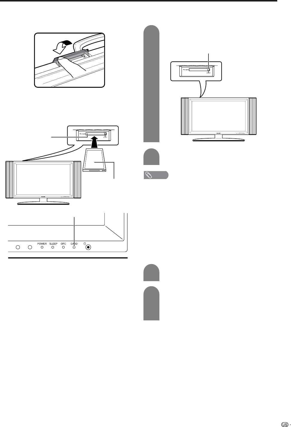
43
Using memory card
Inserting a PC card adapter
• Press in the EJECT button if it is popped out.
• Insert a memory card to a PC card adapter
beforehand. (See page XX.)
• Insert the PC adapter card slowly.
Ejecting the card
• Make sure the card indicator lights up green.
• CARD indicator lights up green when the card is
inserted.
PC CARD slot
CARD indicator
Press EJECT button.
• EJECT button is popped up.
1
2
Press EJECT button again.
EJECT button
NOTE
• Please do not insert a CableCARD (POD card) in the PC
Card slot.
• When “Please insert a PC card” is displayed, eject the
PC card adapter, and then insert the PC card adapter
slowly all the way to the end.
• When over a thousand files are in a card, it takes several
minutes to load. (approx. 5 minutes.)
• Even if the green light is on, you can not record on a card
right after you inserted it.
• Make sure the CARD indicator lights green when you take
out a card. Never take out a card when the CARD indicator
lights red. This may damage the card.
Selecting Still and Video mode
Press CARD and the card mode screen
displays.
1
2
Press c/d to select “Still” or “Video”, and
then press ENTER.
• When in CARD mode, press 0-9, CH a/b,
FAVORITE CH or INPUT to switch either TV or
AV input mode.
Reverse side
Opening the PC CARD slot cover
Use your fingertip to slide the catch in the direction of
the arrow.
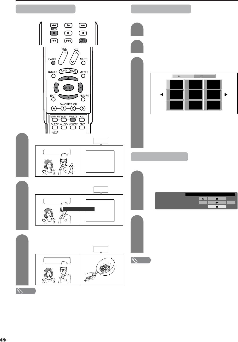
44
Using memory card
Recording a still image
You can record a still image on the card.
Press REC.
1
2
Press FREEZE.
3
Press ENTER to update the still image.
Onion
Tomato
Potato
x 1
x 1
x 1
Still
Cooking Time
Onion
Tomato
Potato
x 1
x 1
x 1
Cooking Time
Still
Still image captured on card.
Displaying a still image
Press CARD and the card mode screen
displays.
1
2
Press c/d to select “Still”, and then press
ENTER.
3
Press a/b/c/d to select a file you want to
display, and then press ENTER.
Still Video
File 1 File 2 File 3
File 4 File 5 File 6
File 7 File 8 File 9
Cooking Time
Still
• “Still image captured on card.” displays.
• To display the files that are in the previous or
next page, select c/d on the index screen and
press ENTER.
• When viewing a still image, by pressing VIEW
MODE the image size changes. Normal – Full.
This function does not work when displaying
the index screen.
Displaying slide show
Repeat steps 1 to 3 in Displaying a still image
above.
• The operation panel displays.
1
2
Press a/b/c/d to select d, and then press
ENTER.
• Slide show starts.
• Operate slide show with the operation panel
appears on the screen.
• To turn off the operation panel, press CARD
on the remote control.
CARD ... STILL 0001/0045 ORDER:NORMAL
PREV.
SLIDE SHOW STOP
NEXT
REPEAT:OFF
NOTE
• See page 42 for operation panel function.
• You can not rotate the image during slide show. Stop slide
show to rotate the image.
NOTE
The list of broadcasting type or input signal not available
for recording:
1COMPONENT input
2HDMI input
3DVI-I input
4Card picture
5Copy guarded signal
6V-chip blocked program
7i.LINK input
8DTV Program
45
Using memory card
Setting/unprotecting Slide Show
You can adjust the interval, order and repeat settings.
4
5
Press a/b to select “Slide Show”, and then
press ENTER.
Press MENU and the MENU screen displays.
2
Press c/d to select “Card Setup”.
3
Press a/b to select “Still Setup”, and then
press ENTER.
Slide Show
My Program
Audio Select
File Operation
Interval
Order
5 Sec.
Repeat
Normal
Off
On
My Program
You can select up to thirty-two pictures and specify
the order for displaying in slide show.
Press a/b/c/d to select the desired slide
show setting, and then press ENTER.
4
Press a/b to select “My Program”, and then
press ENTER.
2
3
Press c/d to select “Setup”, and then press
ENTER.
6
Press a/b/c/d to select the files, and then
press ENTER.
To cancel My Program setting
Performs step 1 and 2 in My Program.
1
2
Press c/d to select “Delete All”, and then
press ENTER.
Description
Set the frame interval for a slideshow.
Set the frame order for a slideshow. See
the right column for My Program setting.
If set to On, the slideshow will play again
after showing the last frame.
Selected item
Interval
Order
Repeat
Press CARD and the card mode screen
displays.
1
6
Repeat steps 1 to 4 in Setting Slide Show.
1
5
Repeats the operation in step 4. (You can
select up to 32 files.)
After selecting all the files you want, press
RETURN to return to MENU.
3
Press c/d to select “Yes”, and then press
ENTER.
• All the registered numbers are cleared.
Audio Select
You can enjoy the audio from TV or other external
equipment during the still image playback.
Press a/b to select “Audio Select”, and then
press ENTER.
2
3
Press a/b/c/d to select the desired sound
output, and then press ENTER.
Repeat steps 1 to 4 in Setting Slide Show.
1

46
Using memory card
Protecting/unprotecting still picture files
You can protect any file you do not want to delete.
5
6
Press a/b to select “File Operation”, and
then press ENTER.
2
3
4
Slide Show
My Program
Audio Select
File Operation
Protect
Delete File
Delete All
Press a/b to select “Protect”, and then
press ENTER.
Press a/b/c/d to select the file you want
to protect, and then press ENTER.
• Protect mark ( ) displays.
• Select the file with a protect mark and press
ENTER to cancel file protect.
Repeat steps 1 to 4 in Audio Select.
1
Repeats the operation in step 4.
After setting the files you want to protect,
press RETURN to return to MENU.
NOTE
• You cannot delete a protected file on the card.
Deleting a still image file
5
6
2
3
4
Press a/b to select “Delete File”, and then
press ENTER.
Repeat steps 1 to 5 in Protecting still
picture files.
1
Press a/b/c/d to select the file you want
to delete, and then press ENTER.
Press c/d to select “Yes”, and then press
ENTER.
NOTE
• You cannot delete a protected file on the card.
• Do not turn off the power or take out a card when deleting
a file. The card may malfunction.
Repeat the operations in steps 7 and 8
above.
After deleting the images you no longer need,
press RETURN to return to MENU.
Deleting all still image files
2
3
Press a/b to select “Delete All”, and then
press ENTER.
Press c/d to select “Yes”, and then press
ENTER.
Repeat steps 1 to 5 in Protecting still
picture files.
1
NOTE
• You cannot delete a protected file on the card.
• Do not turn off the power or take out a card when deleting
a file. The card may malfunction.
47
Using memory card
Recording a motion picture
Use this setting to record images you are currently
watching.
Record with the settings made in “Rec. Mode” and
“Pre Record”.
Press REC to start recording.
• CARD indicator lights up red.
• Recording information displays in the lower
right corner of the screen.
1
2
Press H to stop recording.
To display the remaining record time.
Press DISPLAY while not recording.
• Remaining record time displays in the lower right corner
of the screen.
NOTE
• Do not remove the AC cord from the socket.
• Recording stops if you press POWER on the remote
control while recording.
• When card has no capacity for recording, “Card is full”
displays and stops recording.
• You cannot change the channel or switch the input source
while recording.
Displaying a motion picture
Press CARD and the card mode screen
displays.
1
2
Press c/d to select “Video”, and then press
ENTER.
3
Press a/b/c/d to select the file you want
to play, and then press ENTER.
• Video playback starts.
4
Press CARD again to display the operation
panel.
• See page XX for the operation panel
information.
• When viewing a motion picture, by pressing
VIEW MODE the picture size changes.
Small – Medium – Large.
NOTE
The list of broadcasting type or input signal not available
for recording:
1COMPONENT input
2HDMI input
3DVI-I input
4Card picture
5Copy guarded signal
6V-chip blocked program
7i.LINK input
8DTV Program
Rec. Mode
Use this setting for recording images you are currently
watching. You can select the recording mode (picture
quality) for a motion picture.
5
6
Press a/b to select “Rec. Mode”, and then
press ENTER.
Press MENU and the MENU screen displays.
2
3
Press c/d to select “Card Setup”.
4
Press a/b to select “Video Setup” and then
press ENTER.
Rec. Mode
Pre Record
Repeat Play
File Operation
SP
LP
EP
Press a/b to select the desired mode, and
then press ENTER.
Press CARD and the card mode screen
displays.
1
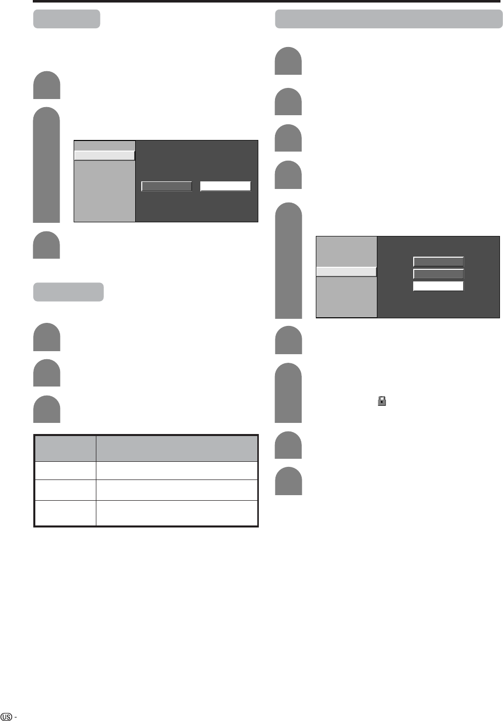
48
Using memory card
Pre Record
You can record the picture slightly before the point
where you pressed the record button, enabling you to
record just the scene you wanted.
Press a/b to select “Pre Record”, and then
press ENTER.
2
3
Rec. Mode
Pre Record
Repeat Play
File Operation
On Off
Press c/d to select “On”, and then press
ENTER.
Repeat steps 1 to 4 in Rec. Mode.
1
Repeat Play
You can specify one file or all files to replay repeatedly.
Press a/b to select “Repeat Play”, and then
press ENTER.
2
3Press a/b to select desired setting, and
then press ENTER.
Repeat steps 1 to 4 in Rec. Mode.
1
Description
No playback or repeat.
Plays back and repeats one file.
Plays back all movie files on the card then
repeats.
Selected item
Off
File
All
Protecting/unprotecting motion picture files
You can protect any file you do not want to delete.
Press a/b to select “File Operation”, and
then press ENTER.
Rec. Mode
Pre Record
Repeat Play
File Operation
Protect
Delete File
Delete All
Press a/b to select “Protect”, and then
press ENTER.
Press a/b/c/d to select the file you want
to protect, and then press ENTER.
• Protect mark ( ) displays.
• Select the file with a protect mark and press
ENTER to cancel file protect.
Press CARD and the card mode screen
displays.
1
5
6
Repeats the operation in step 4.
After setting the files you want to protect,
press RETURN to return to MENU.
Press MENU and the MENU screen displays.
2
3
Press c/d to select “Card Setup”.
4
Press a/b to select “Video Setup”, and then
press ENTER.
7
8
9
49
Using memory card
Deleting a motion picture file
5
6
2
3
4
Press a/b to select “Delete File”, and then
press ENTER.
Press a/b/c/d to select the file you want
to delete, and then press ENTER.
Repeat step 1 to 5 in Protecting motion
picture files.
1
Press c/d to select “Yes”, and then press
ENTER.
NOTE
• You cannot delete a protected file on the card.
• Do not turn off the power or take out a card when deleting
a file. The card may malfunction.
Repeat the operations in steps 7 and 8
above.
After deleting the images you no longer need,
press RETURN to return to MENU.
Deleting all motion picture files
Press a/b to select “Delete All”, and then
press ENTER.
Press c/d to select “Yes”, and then press
ENTER.
2
3
Repeat step 1 to 5 in Protecting motion
picture files.
1
NOTE
• You cannot delete a protected file on the card.
• Do not turn off the power or take out a card when deleting
a file. The card may malfunction.
Format
4
Press c/d to select “Yes”, and then press
ENTER.
Press MENU and the MENU screen displays.
1
2
Press c/d to select “Card Setup”.
3
Press a/b to select “Format” and then
press ENTER.
NoYes
NOTE
• Formatting a card deletes all files including the ones which
set to protect.
• Do not turn off the power or take out a card while it is
being formatted.
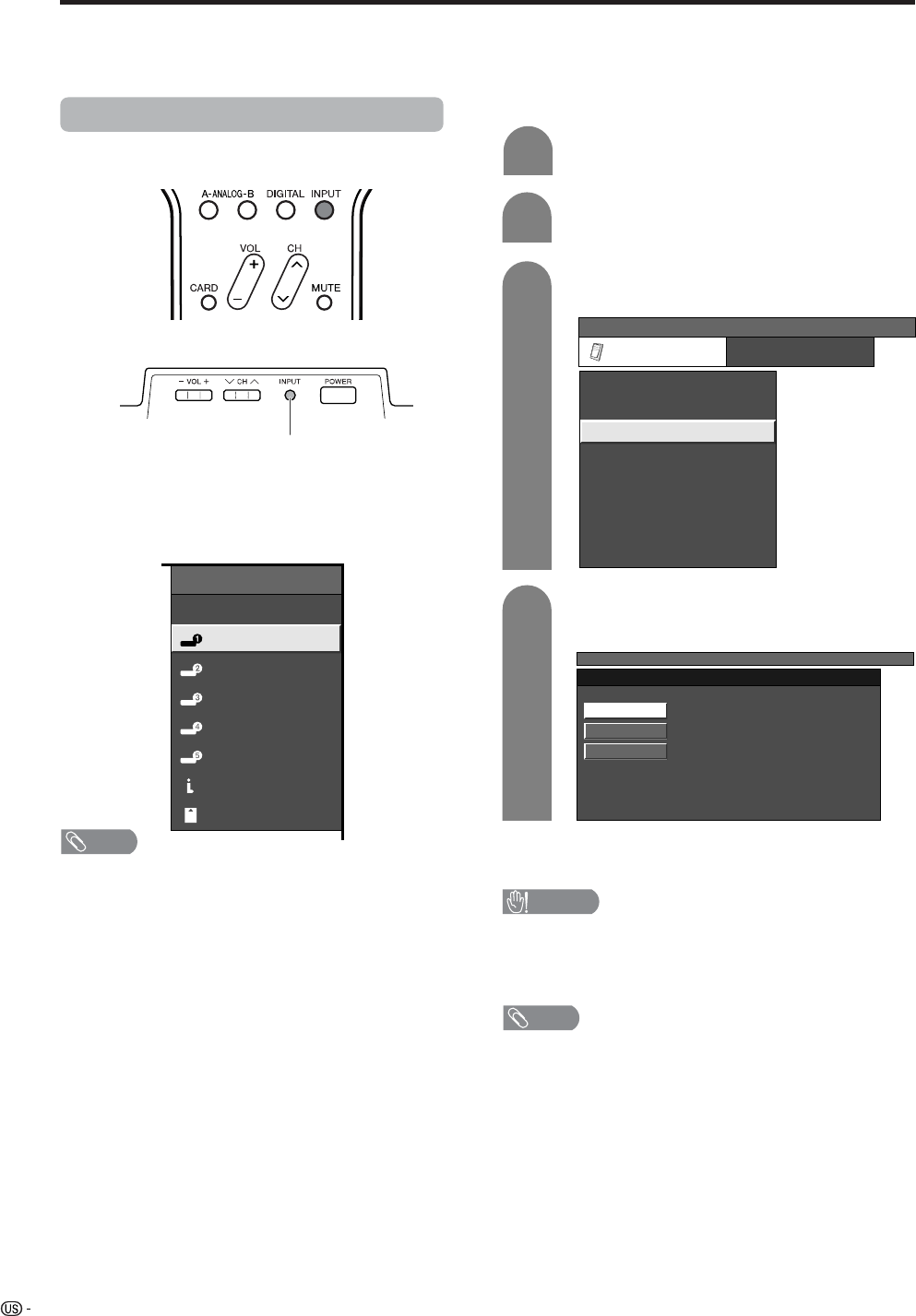
50
Using external equipment
You can connect many types of external equipment to your System, like a DVD player, VCR, Digital TV tuner, PC,
HDMI equipment, game console and camcorder. To view external source images, select the input source from
INPUT on the remote control unit or on the Display.
CAUTION
• To protect all equipment, always turn off the TV before
connecting to a DVD player, VCR, Digital TV tuner, PC,
HDMI equipment, game console, camcorder or other
external equipment.
NOTE
• See pages XX to XX for external equipment connection.
• Please refer to the relevant operation manual (DVD player,
PC, etc.) carefully before making connections.
• Each time INPUT is pressed, the input source toggles.
• Refer to your external equipment operation manual for
the signal type.
Displaying an external equipment image
Explanation here is for the setting when connecting
DVD to INPUT1 terminal.
INPUT button
To watch a DVD image, select “INPUT1” from “INPUT
SOURCE” menu using INPUT on the remote control
unit or on the Display. (See page XX.)
INPUT SOURCE
TV
INPUT1
INPUT2
INPUT3
INPUT4
INPUT5
i.LINK
CARD
1
MENU
[Option ... Input Select]
Auto
COMPONENT
Video
For INPUT1 signal
Select the desired signal type.
The setting is stored and can be selected on the
“INPUT SOURCE” menu.
Press MENU and the MENU screen displays.
2
3
Press a/b to select “Input Select”, and then
press ENTER.
4
Press c/d to select “Option”.
MENU
[Option ... Input Select]
Option
Input Select
Digital Noise Reduction
Output Select
Audio Only
Quick Shoot
[Fixed]
[Auto]
[Low]
[Off]
Center Channel Input
Caption Setup
[Off]
Title Display type [No]
NOTE
• If the image does not come in clearly, you may need to
change the input signal type setting on the “Input Select”
menu.
Selecting the INPUT signal
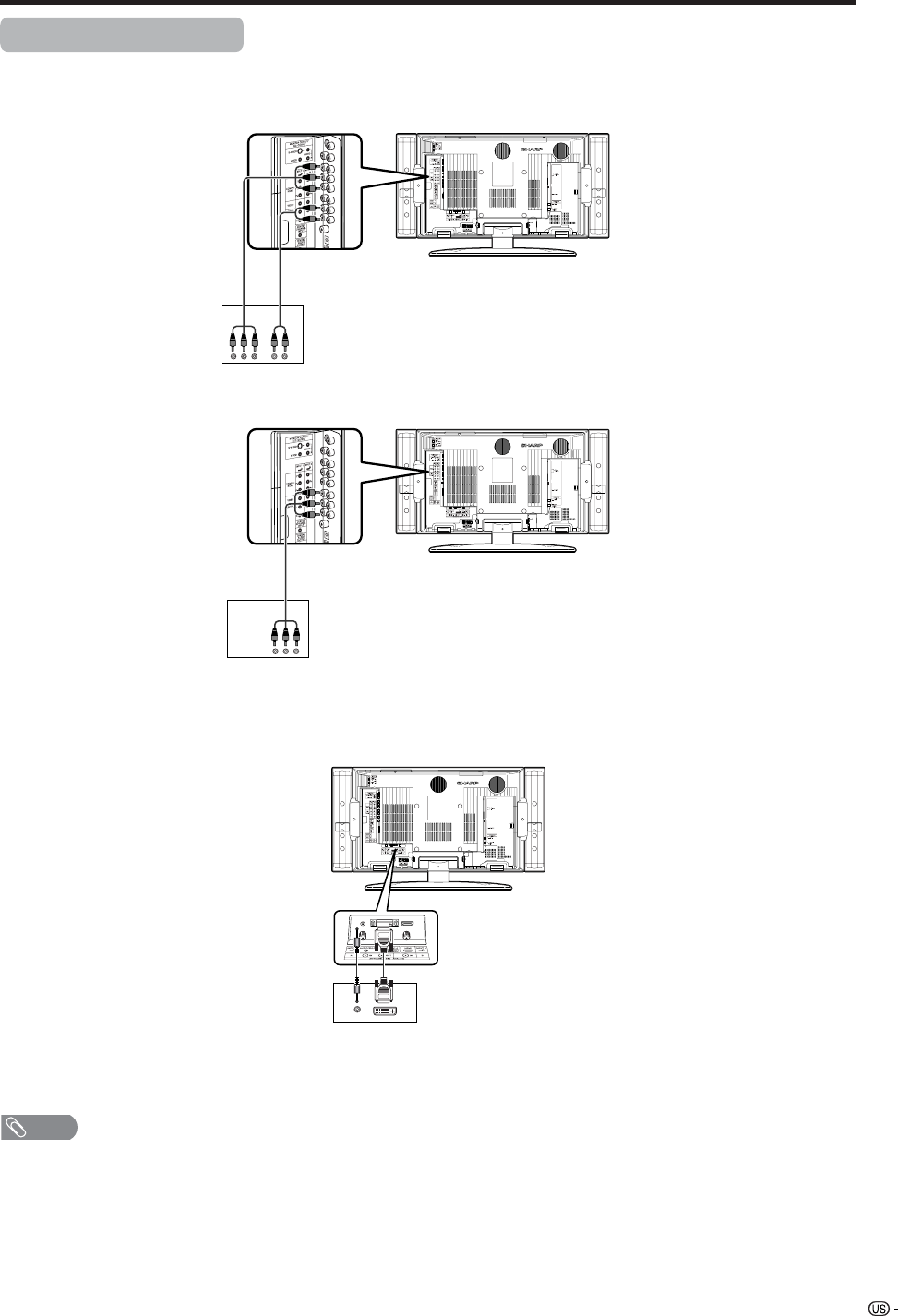
51
Using external equipment
Connecting a DVD player
You can use the INPUT 1, INPUT 2, INPUT 4 or INPUT 5 terminals when connecting to a DVD player and other
audiovisual equipment.
NOTE
• See page 54 for connecting a DVD player with HDMI
terminal.
DVD player
Component
video cable
(commercially
available)
Audio cable
(commercially available)
AV cable (commercially
available)
DVD player
ø 3.5 mm stereo minijack cable
(commercially available) DVI cable (Commercially available)
When using component cable.
When using composite cable.
When using DVI cable. (INPUT 5)
DVD player
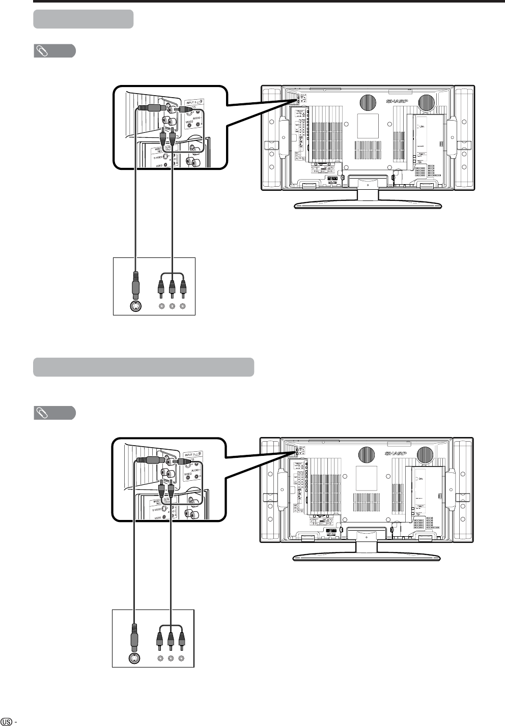
52
Using external equipment
VCR
AV cable
(commercially available)
Connecting a VCR
You can use the INPUT 3 terminal when connecting a VCR and other audiovisual equipment.
Game console/Camcorder
S-video cable
(commercially
available)
Connecting a game console or camcorder
A game console, camcorder and some other audiovisual equipment are conveniently connected using the
INPUT 3 terminals.
NOTE
• The S-video terminal has priority over the video terminals.
AV cable
(commercially available)
S-video cable
(commercially
available)
NOTE
• The S-video terminal has priority over the video terminals.
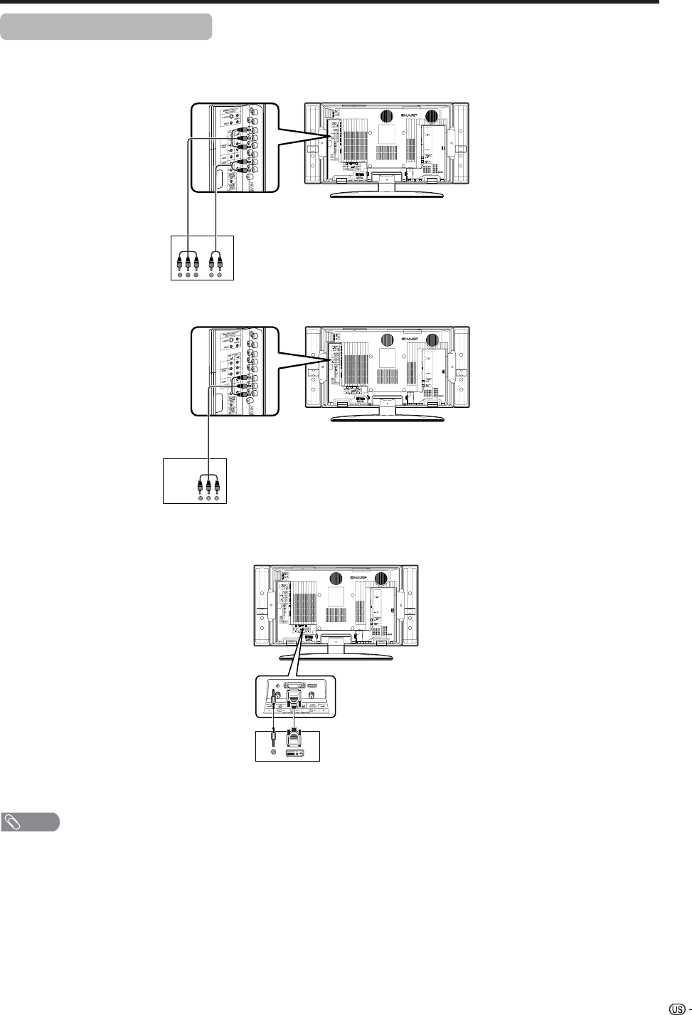
53
Using external equipment
Connecting a Digital TV STB
You can use the INPUT 1, INPUT 2, INPUT 4 or INPUT 5 terminals when connecting a Digital TV STB and other
audiovisual equipment.
Digital TV STB
Component video cable
(commercially available) Audio cable
(commercially available)
NOTE
• See page 54 for connecting a Digital TV STB to HDMI terminal.
AV cable
(commercially available)
Digital TV STB
Digital TV STB
ø 3.5 mm stereo minijack cable
(commercially available) DVI cable (Commercially available)
When using component cable.
When using composite cable.
When using DVI cable. (INPUT 5)
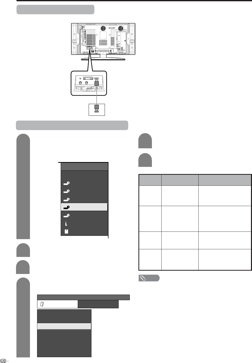
54
Using external equipment
Connecting HDMI equipment
You can use the INPUT 4 terminal when connecting an HDMI equipment.
HDMI equipment
HDMI cable
(Commercially available)
Displaying an image from HDMI equipment
To watch an HDMI equipment image, select
“INPUT4” from “INPUT SOURCE” menu
using INPUT on the remote control unit or
on the Display. (See page 66.)
INPUT SOURCE
TV
INPUT1
INPUT2
INPUT3
INPUT4
INPUT5INPUT5
CARD
i.LINK
1
Press MENU and the MENU screen displays.
2
3
Press a/b to select “HDMI Setup”, and then
press ENTER.
4
Press c/d to select “Option”.
MENU [Option ... HDMI Setup]
Option
Digital Noise Reduction
Output Select
Center Channel Input
Caption Setup
Audio Only
Quick Shoot
[Fixed]
[Off]
HDMI Setup
[Low]
[Off]
5
Press a/b to select the desired item and
press ENTER.
Press a/b/c/d to select the desired setting
and press ENTER.
6
NOTE
• Refer to your external equipment operation manual for
the signal type.
Selectable items
Auto/RGB/YCbCr
4:4:4/YCbCr 4:2:2
Auto/ITU601/
ITU709
Standard/
Out of standard
Enable/Disable
HDMI Setup
items
Signal
Type
Color
Matrix
Dynamic
Range
Auto View
Description
Select the signal type from
an HDMI terminal. Unless
the image quality looks
obviously poor, select Auto.
Select the internal color
space conversion method
when an RGB signal is
input. Normally, select
Auto.
Select the signal amplitude
range. Normally, select
Standard.
Set whether or not to use
VIEW MODE based on
signal recognition,
including an HDMI signal.
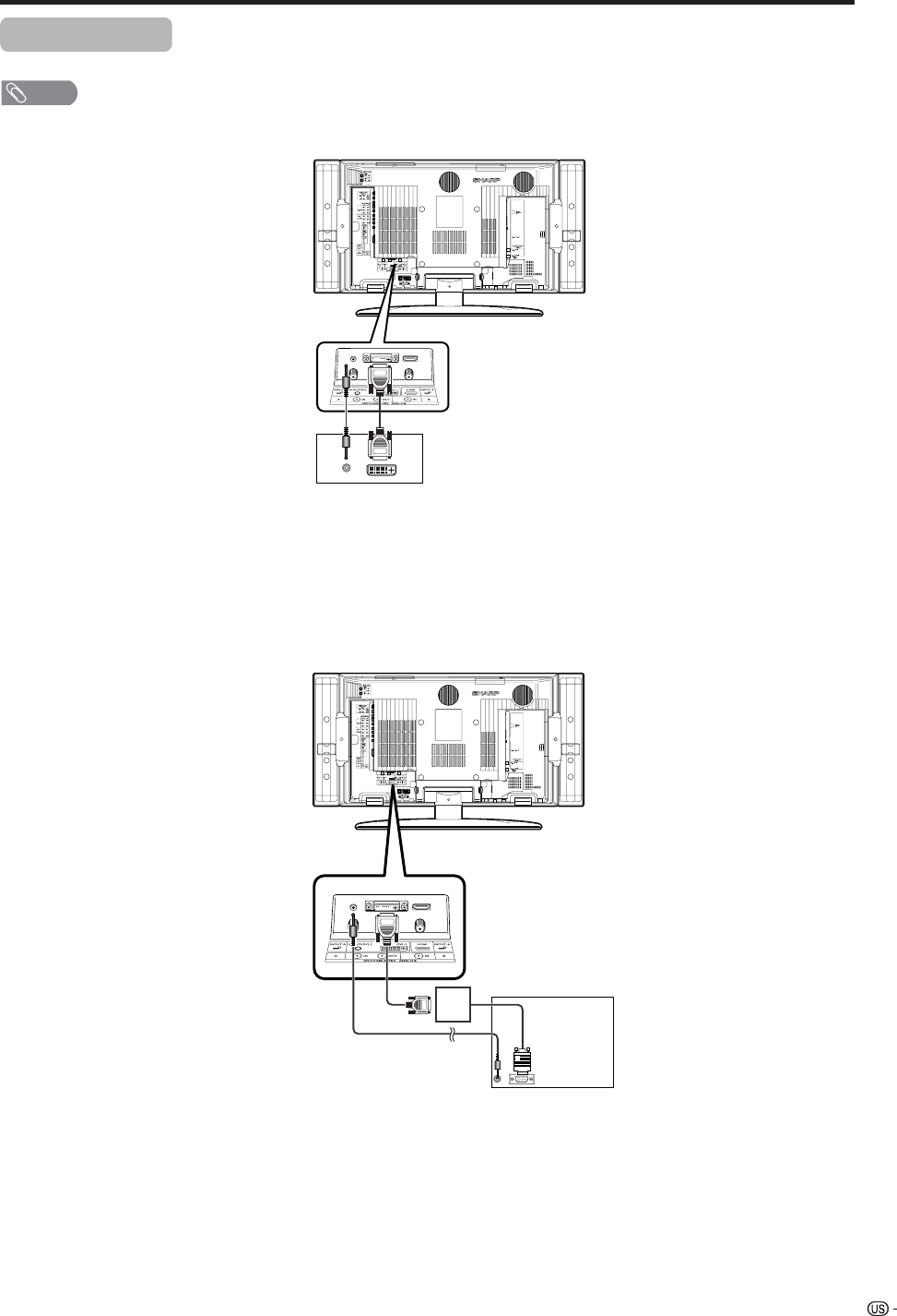
55
Using external equipment
Connecting a PC
Use the INPUT 5 terminal to connect a PC.
NOTE
• Refer to page 81 for a list of PC signals compatible with the TV.
PC with DVI terminal
ø 3.5 mm stereo minijack cable
(commercially available) DVI cable (Commercially available)
ø 3.5 mm stereo minijack cable
(commercially available)
PC with analog RGB terminal
RGB/DVI conversion cable
(Commercially available)
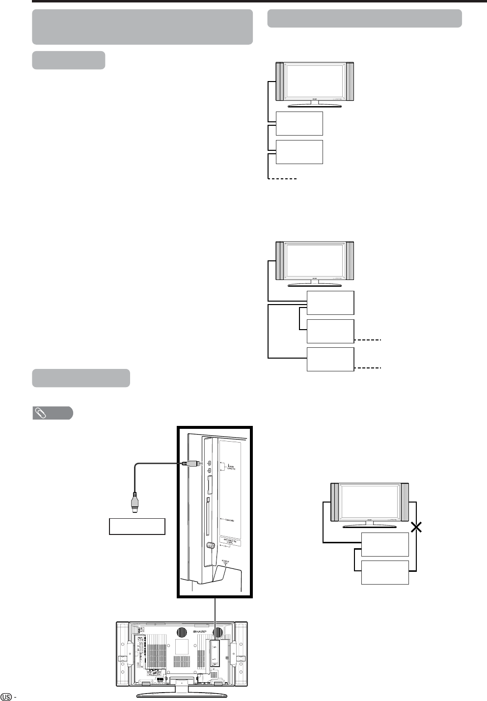
56
Connecting D-VHS Decks (i.LINK
connection)
Using external equipment
About i.LINK
i.LINK is an interface connection using a serial
transfer system and is able to transfer multimedia
data, such as digital images and digital sound,
between devices that have i.LINK terminals.
i.LINK is a term defined in the IEEE 1394 (Institute of
Electrical and Electronics Engineers) standard.
Currently, the transfer speeds are at 100 Mbps, 200
Mbps and 400 Mbps, each of them expressed as
S100, S200 and S400 respectively. On this TV, the
maximum speed is 400 Mbps.
i. LINK devices that can be connected to this
TV.
Only D-VHS decks can be connected to this TV.
Other devices such as DVD recorders, digital video
cameras, computers or computer peripheral devices
do not meet the specifications for this TV and
therefore, cannot be connected.
Materials that can be recorded with the i.LINK
Only digital programs can be recorded by D-VHS
decks connected to this TV using the i.LINK. i.LINK
recording is not compatible with ground-wave
broadcasts or external input signals (INPUT
terminals 1 through 5).
i.LINK connection
Only an i.LINK cable is needed
to connect the TV and the D-VHS
deck. (VIDEO, S-VIDEO, and
AUDIO terminals need not be
connected.)
D-VHS deck
Connecting two or more D-VHS decks
Up to 16 D-VHS decks can be connected using a
daisy-chain connection with i.LINK cables.
When 3 or more D-VHS decks are connected,
branch connection can be used. With branch
connections, up to 62 D-VHS decks can be
connected.
Cautions regarding i.LINK connection
• Please use S400 type i.LINK cables.
• Some i.LINK devices may not relay data if their power
is off. This TV can relay data during power off, by
selecting “Yes” in the “Stand-by Mode” option in
“i.LINK setup”. (See Page 57.)
• Please do NOT use a loop connection as shown in
the diagram.
• When using the i.LINK, do not turn off the power of,
or pull the cable from i.LINK devices, even if that
i.LINK devices is not in use. This may affect the
picture and the sound from a D-VHS deck in use.
• If devices such as a DVD recorders, digital video
cameras, computers and computer peripheral
devices which are not compatible with this TV, are
connected to the TV using i.LINK, other i.LINK
connections may be disrupted.
E.g. When only one D-VHS deck is connected:
NOTE
• Please make sure the
shapes of the terminal
and the plug match,
and insert the plug into
the terminal straight,
not on an angle.
• Use either one of the
terminals. These two
terminals do not differ in
quality or function.
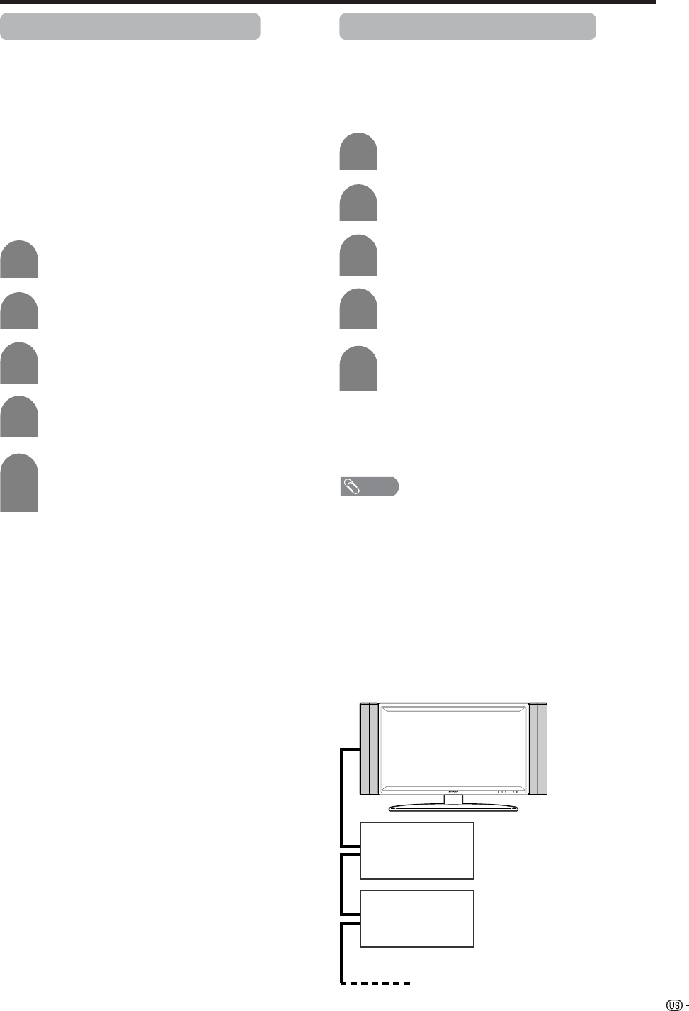
57
Using external equipment
Setting the recording mode (i.LINK)
• The function for automatically adjusting the recording
mode of connected D-VHS decks can be turned on
or off.
• Since most of the currently available D-VHS decks
automatically recognize the transfer rates of the
pictures and sound being recorded and control the
recording mode accordingly, you should always set
this Mode to “No” in normal circumstances.
• Depending on the D-VHS deck used and the type of
broadcast being recorded, this TV may not adjust
the recording mode properly. In this case, please
set the “Recording Mode” to “No”.
Press MENU and the MENU screen displays.
Press c/d to select “Digital Setup”.
Press a/b to select “i.LINK Setup”, and then
press ENTER.
1
2
3
Press a/b to select “Recording Mode”, and
then press ENTER.
4
Press c/d to select “Yes” or “No”, and then
press ENTER.
• Normally, this should be set to “No”.
5
Setting the Stand-by Mode (i.LINK)
• Power consumption during stand-by mode can be
minimized by changing the setting of the “Standby
Mode” in “i.LINK Setup”.
• When i.LINK is not in use, select “No” in “Stand-by
Mode”.
Press MENU to display the MENU.
Press c/d to select “Digital Setup”.
Press a/b to select “i.LINK Setup”, and then
press ENTER.
1
2
3
Press a/b to select “Stand-by Mode”, and
then press ENTER.
4
Press c/d to select “Yes” or “No”, and then
press ENTER.
5
“Yes”: Power continues to pass through the i.LINK
circuit so data can be relayed.
“No”: Power consumption is minimized during stand-
by mode. Data cannot be sent at this setting.
NOTE
• When the main power of the TV is in standby mode
(POWER indicator lights up in red), i.LINK control
commands cannot be received from a D-VHS deck. This
does not change even if the “Stand-by Mode” is set to
“Yes”. To control the TV from a D-VHS deck, turn the TV
power on (POWER indicator lights up in green).
• Data cannot be relayed between i.LINK devices when all
the following conditions are met: 1) More than one i.LINK
device is connected to the TV with i.LINK cables, 2)
“Stand-by Mode” is set to “No”, and 3) The main power of
the TV is in standby mode (POWER indicator lights up in
red). When the TV is connected between two i.LINK
devices in series, select “Yes” in “Stand-by Mode” or
connect the TV at an end of the series as shown in the
diagram.
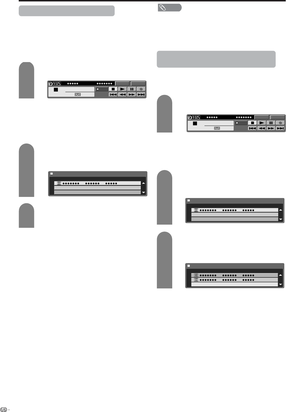
58
Using external equipment
Selecting a D-VHS deck (i.LINK)
• In order to control a D-VHS deck from the TV, you
must first choose the D-VHS deck to be controlled.
• One D-VHS deck can be chosen from up to 16 i.LINK
connected decks.
• All D-VHS decks connected with i.LINK cables
should automatically appear in the selection screen.
Press i.LINK to display the i.LINK control
panel.
Press a/b/c/d to select “Model” and press
ENTER.
• Selection screen appears.
Press a/b to select a device, and then press
ENTER.
• The control panel for the D-VHS deck appears.
1
2
3
Disabling the TV’s operation of a D-VHS
deck (i.LINK)
• By disabling the TV’s operation of a D-VHS deck,
the deck can be operated from another i.LINK
device.
Press i.LINK to display the i.LINK control
panel.
Press a/b/c/d to select “Model” and press
ENTER.
• Selection screen appears.
1
2
3
NOTE
• Devices that cannot be used with this TV will not appear
in the selection screen.
• When an item in the selection screen is grayed out, the
item is not recognized by the TV and cannot be selected.
(The item may not be connected properly.)
• When there is no D-VHS deck connected, the
message “No i.LINK model is available” appears. In
this case, please connect a D-VHS deck. (See page
57.)
• When there is no D-VHS deck selected, the selection
screen appears. In this case, please go to step 3. • When there is no D-VHS deck connected, “No i.LINK
model is available” appears. Please connect one.
(See page 57.)
• When there is no D-VHS deck selected, the selection
screen appears. Please go to step 3.
Press b to select “Cancel Connection” and
press ENTER.
• Operation of the D-VHS deck from the TV is
disabled.
Model Input
PLAY
PWR
D-VHSStop
1
00:00:00
Type Maker Model
Model Input
PLAY
PWR
D-VHSStop
1
00:00:00
Type Maker Model
Type
Cancel Connection
Maker Model
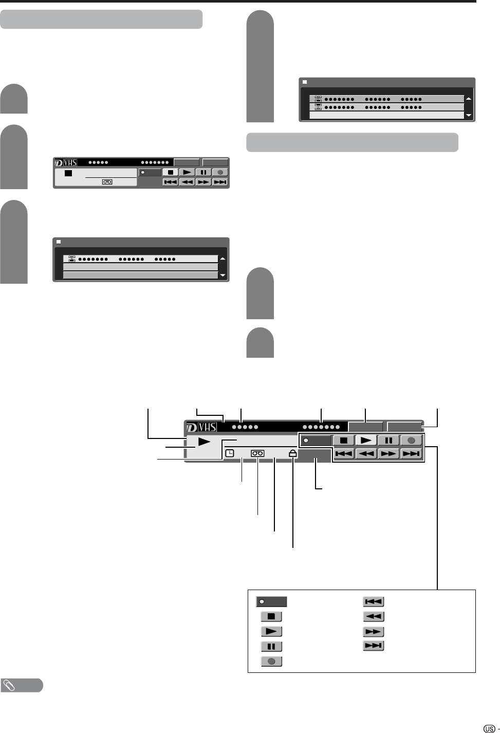
59
Using external equipment
Deleting a preset D-VHS deck (i.LINK)
• Preset D-VHS decks can be selected from a list.
• If a D-VHS deck is connected, it cannot be deleted
from the list.
Press i.LINK to display the i.LINK control
panel.
Press a/b/c/d to select “Selecting a
device”, and then press ENTER.
Press a/b to select a device to be deleted,
and then press ENTER.
1
2
3
Controlling an i.LINK device
• An i.LINK compatible D-VHS deck can be controlled
from the TV using the i.LINK control panel on the
screen.
• The steps in “i.LINK Setup” on page XX need to be
completed beforehand.
• Please also refer to the operation manual of the D-
VHS deck to be used with this TV.
Basic operation
Press i.LINK to display the i.LINK control
panel.
• The i.LINK button is also used to exit the i.LINK
control panel.
Press a/b/c/d to select a function, and
then press ENTER.
1
2
Press c to select “Delete”, and then press
ENTER.
• The selected D-VHS deck is deleted from the
list.
• Select “Cancel” to undelete a device.
4
The i.LINK control panel
NOTE
• The input selection button is used to select either digital broadcasting or i.LINK input.
Model Input
PLAY
PWR
D-VHSStop
1
00:00:00
Type Maker Model
Type
Cancel Connection
Maker Model
Model Input
1
D-VHS PLAY
PWR
PWR
00:00:00
Cassette inserted
Type of Videotape/Tape Format
Write Protect on
(When the defeat tabs are broken recording is impossible)
Function selected
with the cursor
Power On/Off
STOP
PLAY
PAUSE
REC START
Skip back
REWIND
FAST FORWARD
Skip forward
Status Display
i.LINK device
number Maker's name Model
Go to Model
Selection
screen Select input
Current operation
Tape Counter
Timer Status
(D-VHS recorder can not be
operated when timer is set)

60
NOTE
• Even when a connected D-VHS deck is playing, input
signal can be switched to digital broadcasting by shifting
the cursor to the input selection button and pressing
ENTER.
• This TV may not be able to operate some D-VHS decks
using the control panel, or to display picture and/or sound
input from some D-VHS decks.
• Depending on the D-VHS deck, this TV’s i.LINK may not
allow viewing of VHS and S-VHS tape or analog recorded
D-VHS tape. In this case, connect the D-VHS deck’s
analog output with the TV’s analog input, and switch the
TV’s input mode to external input.
• If a D-VHS deck is operated with the TV’s control panel
during timer recording, the recording may fail. Do not use
the TV’s control panel to operate the D-VHS deck during
timer recording.
• When the TV’s control panel is used to record a program,
what is recorded with the D-VHS deck are the pictures
and sound of the digital program that the TV is receiving.
• To record the picture and sound of a digital program which
the TV is receiving, use D-VHS tape. VHS or S-VHS tape
will not record.
• The i.LINK control panel cannot be used during timer
recording.
• The i.LINK control panel cannot be displayed together
with the TV Guide On Screen™or other menus.
• There may be some programs which D-VHS decks cannot
record.
• With some D-VHS decks, the quality of the picture may
be distorted during fast forwarding or rewinding.
• IEEE 1394 is the IEEE’s international standard.
• i.LINK and the i.LINK logo are registered trademarks of
Sony Electronic, Inc.
• A copy protection technology is used on D-VHS decks
that incorporate copyright protection. This technology has
received the approval of the Digital Transmission Licensing
Administrator (DTLA), an organization that administers
copyright protection technologies. Some picture and
sound data have restrictions on duplication. Such data
cannot be digitally copied using the i.LINK. Some picture
and sound data may not be able to be sent back and
forth between a D-VHS deck that has DTLA copyright
protection technology and one that does not.
Using external equipment
Automatic input switching to i.LINK
• Input mode can be set to automatically switch to
i.LINK when a D-VHS deck connected to the TV is
played.
Press MENU to display the MENU screen.
Press c/d to select “Digital Setup”, and then
press ENTER.
Press a/b select “i.LINK Autoswitch”, and
then press ENTER.
1
2
4
Press c/d to select “Yes”, and then press
ENTER.
5
i.LINK Autoswitch
Stand-by Mode
Recording Mode
Yes No
Press a/b to select “i.LINK setup”, and then
press ENTER.
3
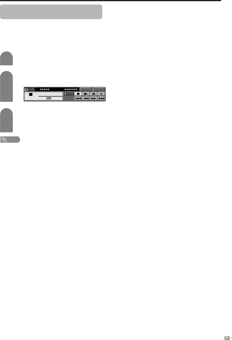
61
Using external equipment
Recording digital programs with a D-VHS
deck (i.LINK)
• Before commencing this procedure, the steps in
“i.LINK Setup” on page 58 need to be completed
beforehand.
• Please also refer to the operation manual of the D-
VHS deck to be used with this TV.
Select a digital program to be recorded.
Press i.LINK to display the i.LINK control
panel.
Press a/b/c/d to select E, and then press
ENTER.
• Recording starts.
• Select E and press ENTER to stop recording.
1
2
3
NOTE
• Input mode cannot be switched to i.LINK during recording.
• Some D-VHS decks may not be able to be operated using
the TV’s i.LINK control panel.
• When a D-VHS deck connected to the TV is under timer
recording, the deck cannot be operated using the TV’s
control panel.
• When the TV’s control panel is used to record a program,
what is recorded with the D-VHS deck are the pictures
and sound of the digital program that the TV is receiving.
• To record the picture and sound of a digital program which
the TV is receiving, use D-VHS tape. VHS or S-VHS tape
will not record.
• The i.LINK control panel cannot be used during timer
recording.
Model Input
PLAY
PWR
D-VHSStop
1
00:00:00
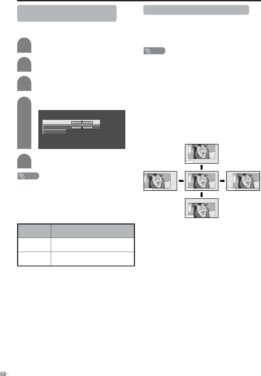
62
Useful adjustment settings
Image position (AV input mode
only)
For adjusting a picture’s horizontal and vertical
position.
1
2
Press MENU and the MENU screen displays.
Press c/d to select “Setup”.
4
5
3
Press a/b to select “Position”, and then
press ENTER.
Press a/b to select “H-Pos.” or “V-Pos.”.
Reset
H-Pos. [0] –10 +10
V-Pos. [0] –20 +20
Press c/d to adjust the item to your desired
position.
Description
Centers the image by moving it to the left
or right.
Centers the image by moving it up or
down.
Selected item
H-Pos.
V-Pos.
NOTE
• For resetting all adjustment items to the factory preset
values, press a/b to select “Reset”, and then press
ENTER.
•Adjustments are stored separately according to input
source.
• You can easily move the image position as shown on this
page, but when the power is switched off the image will
return to the previously memorized position.
Moving the picture on the screen
You can move the picture around on the screen.
Press a/b/c/d to move an image on the screen to
the desired position. Press ENTER to return to the initial
image position.
NOTE
• While pressing a/b/c/d, an on-screen image,
“Adjusting Position” displays to the desired position.
• This setting cannot be stored. Once the TV shuts down or
enters standby mode, the setting is erased. To move the
picture around the screen again, you must perform the
above procedure again.
• The image position setting using the steps on page 63
can be stored. Select either according to your objectives.
• “TV”, “INPUT1”, “INPUT2”, “INPUT3” and “INPUT4” can
each adjust the image position setting on this page. The
same for view modes.
• An on-screen image from PC and card cannot be moved
around.
• Even when the image fills the screen, its position can be
adjusted with this function.
• Press ENTER to reset the image to original positions.
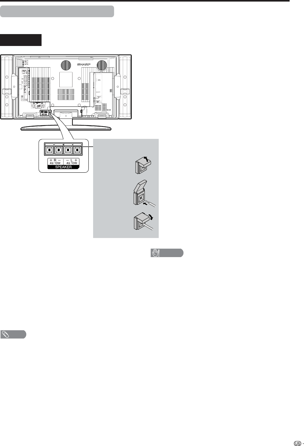
63
Rear view
Useful adjustment settings
Connecting external speakers
When using external speakers
• Change the speaker setting to external speakers. (See
page 64.)
Make sure to connect the speaker terminal and
cable polarity (L,+) properly
• The speaker terminals have plus (L) and minus (+)
polarity.
• Plus is red and minus is black.
• The cables are also divided into plus and minus.
• When connecting the left/right speakers, be sure to
connect the plus/minus terminals with the correct cables.
NOTE
• Unplug the AC cord from the AC outlet before installing
the speakers.
CAUTION
• Make sure external speakers have 4 ohm and 10 watt
specifications.
• Connect the plus/minus terminals with the correct cables.
Incorrect connection may cause a short.
How to connect the
speaker cable
Push down
the tab.
Insert the
end of the
cable.
11
11
1
22
22
2
33
33
3Lift the tab
back up.
64
Useful adjustment settings
Audio Quality Control
Audio Quality Control automatically optimizes the audio
quality to suit internal (supplied) speakers.
Press MENU and the MENU screen displays.
Press c/d to select “Setup”.
1
2
Press c/d to select “Equalizer” or “Flat”, and
then press ENTER.
5
Press a/b to select “Speaker Setup”, and
then press ENTER.
3
Press a/b to select “Audio Quality Control”,
and then press ENTER.
4
Description
Sets the optimum Audio Quality Control for
the attached speakers.
When you are using your own speakers,
output the original sound without using
Audio Quality Control.
Selected item
Equalizer
Flat
NOTE
• When DOLBY Virtual is on, Audio Quality Control
automatically sets to Flat.
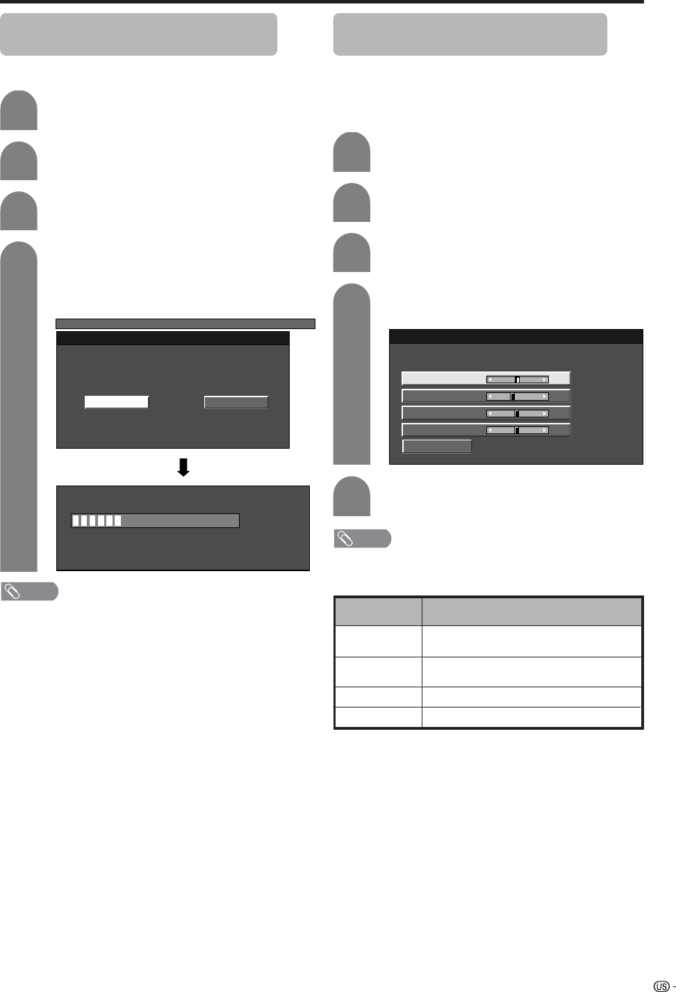
65
Useful adjustment settings
1
2
Auto Sync. adjustment (PC input
mode only)
For automatically adjusting the PC image.
Press MENU and the MENU screen displays.
Press c/d to select “Setup”.
4
3
Press a/b to select “Auto Sync.”, and then
press ENTER.
Press c/d to select “Yes”, and then press
ENTER.
• Auto Sync. starts and “Now adjusting the
image” displays.
MENU
[Setup ... Auto Sync.]
NoYes
NOTE
• When Auto Sync. is successful, “Auto Sync completed
successfully” displays. If not, Auto Sync. failed.
• Auto Sync. may fail even if “Auto Sync completed
successfully” displays.
• Auto Sync. may fail if the computer image has low
resolution, has unclear (black) edges, or is moved while
executing Auto Sync.
• Be sure to connect the PC to the TV and switch it on before
starting Auto Sync.
Fine Sync. adjustment (PC input
mode only)
Ordinarily you can easily adjust the picture as
necessary to change image position using Auto Sync.
In some cases, however, manual adjustment is needed
to optimize the image.
Press MENU and the MENU screen displays.
Press c/d to select “Setup”.
Press a/b to select “Fine Sync.”, and then
press ENTER.
Press c/d to adjust the item to your
desired position.
NOTE
• For resetting all adjustment items to the factory preset
values, press a/b to select “Reset”, and then press
ENTER.
30%
Description
Centers the image by moving it to the left
or right.
Centers the image by moving it up or
down.
Adjusts the clock frequency.
Adjusts the clock phase.
Selected item
H-Pos.
V-Pos.
Clock
Phase
Reset
H-Pos. [90] – +
V-Pos.
Clock
Phase
[39]
[90]
[20]
–
–
–
+
+
+
1
2
4
3
5
Press a/b to select the specific
adjustment item.
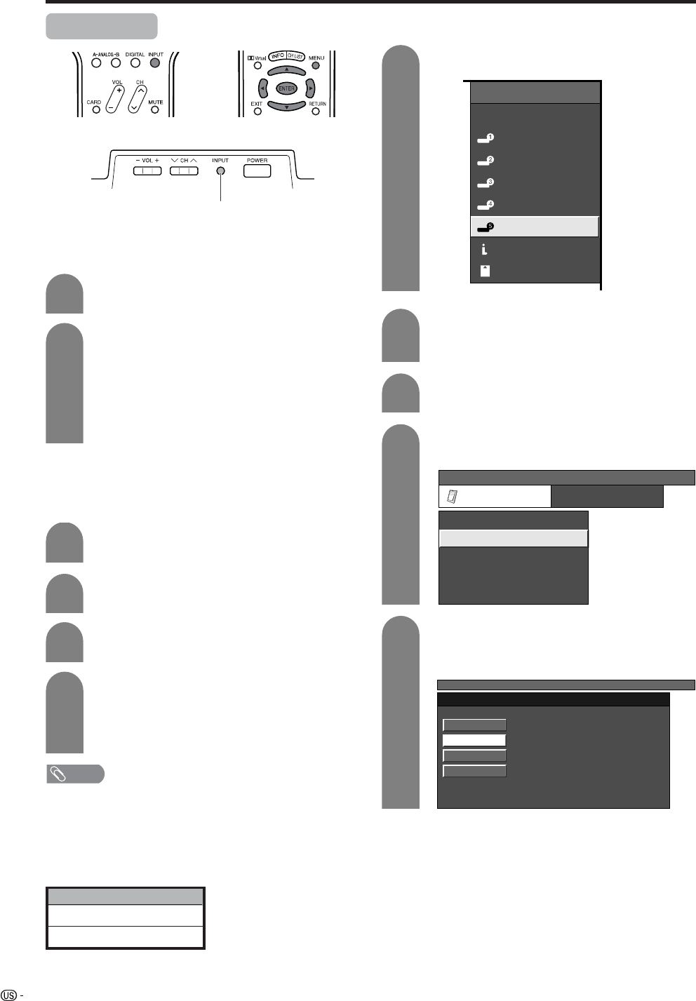
66
Useful adjustment settings
Input Select
Press MENU and the MENU screen displays.
1
2
3
Press c/d to select “Option”.
Press a/b to select “Input Select”, and then
press ENTER.
Press INPUT.
• A list of selectable sources appears.
Press INPUT again to select the input source.
• An image from the selected source
automatically displays.
• You can also select the input source by
pressing a/b.
• If the corresponding input is not plugged in,
you cannot change the input. Be sure to
connect the equipment beforehand.
1
2
Selecting input signal type
For setting the signal type of external equipment
connected to INPUT 1 and Input 2 terminals.
4
Press a/b to select a signal type you want
to set, and then press ENTER.
• If the selected signal type is incorrect, images
are not displayed or displayed without any
color.
NOTE
• If you set INPUT1 and INPUT2 to Auto, the TV will
automatically select the input signal.
• Check the operation manual of the external equipment
for the signal type.
• Setting INPUT 1 and INPUT 2 signal selection to “Auto”
when other equipment is connected will result in the
following connectivity priority.
Selecting input source
Use this menu to select the input source.
INPUT 1 and INPUT 2
1. COMPONENT VIDEO
2. VIDEO
Press INPUT to select INPUT5.
Press MENU and the MENU screen displays.
Press a/b to select the equipment
connected to INPUT 5 terminal, and then
press ENTER.
1
2
4
3
5
Display
INPUT button
INPUT SOURCE
TV
INPUT1
INPUT2
INPUT3
INPUT4
INPUT5INPUT5
i.LINK
CARD
Press c/d to select “Option”.
Press a/b to select “Input Select”, and then
press ENTER.
MENU
[Option ... Input Select]
Option
Input Select
Output Select
Audio Only
Quick Shoot
[Fixed]
[ANALOG PC]
[Off]
Center Channel Input [Off]
MENU [Option ... Input Select]
DIGITAL PC
ANALOG PC
DIGITAL AV
ANALOG AV
DVI input signal setting
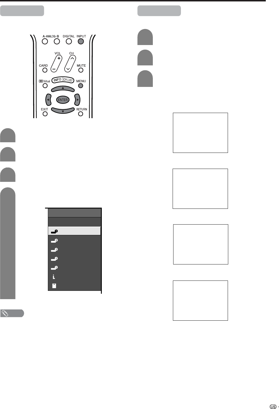
67
Useful adjustment settings
Input Label
Lets you set the input terminal displayed using the
INPUT SOURCE menu or channel display.
Press MENU and the MENU screen displays.
3
4
Press c/d to select “Setup”.
Press a/b to select “Input Label”, and then
press ENTER.
1
2
INPUT SOURCE
TV
DVD
INPUT2
INPUT3
INPUT4
INPUT5INPUT5
i.LINK
CARD
Press a/b/c/d to select the new name for
the channel, and then press ENTER.
(Example)
NOTE
• You cannot change labels if the INPUT SOURCE is TV,
i.LINK or CARD.
Repeat steps 1 and 2 in Input Label.
1
2
Press a/b to select the desired mode, and
then press ENTER.
Press a/b to select “Picture Flip”, and then
press ENTER.
3
[Standard]: normal image.
[Mirror]: mirror image.
ABC
ABC
ABC
ABC
[Upside Down]: upside down image.
[Rotate]: rotated image.
Picture Flip
You can set the orientation of the picture.
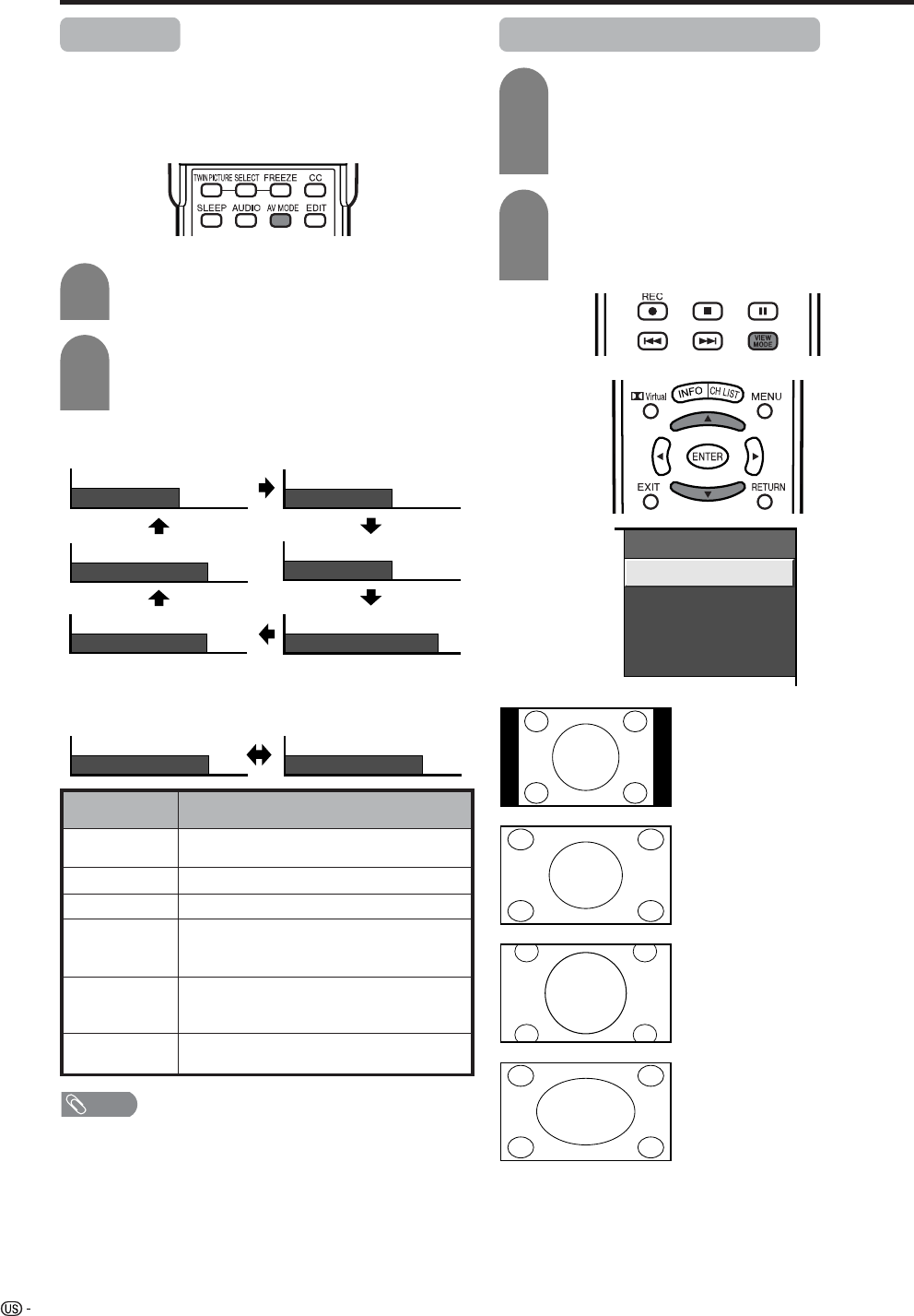
68
Useful adjustment settings
AV MODE
AV MODE gives you six viewing options to choose
from to best match environment of the System, which
can vary due to factors like room brightness, type of
program watched or the type of image input from
external equipment.
Description
For a highly defined image in a normally
bright room
For a movie
Lowers image brightness for easier viewing
Allows the user to customize settings as
desired. You can set the mode for each
input source.
Changing image and sound settings to
factory preset values. No adjustments are
allowed.
For a clear-cut image emphasizing high
contrast for sports viewing
Selected item
STANDARD
MOVIE
GAME
USER
DYNAMIC
(Fixed)
DYNAMIC
Press AV MODE.
• Present AV MODE displays.
Press AV MODE again before the mode
displayed on the screen disappears.
• The mode changes as shown below.
1
2
Mode selection for TV, INPUT 1 to 5, i.LINK and CARD
mode (Example)
Mode selection for the PC terminal
(Example)
AV MODE: MOVIE
AV MODE: STANDARD
AV MODE: DYNAMIC AV MODE: GAME
AV MODE: USER [ANALOG-A]
AV MODE: DYNAMIC (Fixed)
AV MODE: STANDARD AV MODE: USER [PC]
View mode for 4:3 Programs
Press VIEW MODE.
• The View mode menu displays.
• The menu lists the view mode options
selectable for the type of video signal currently
received.
Side Bar: Suitable for viewing
conventional 4:3
programs in their
normal format.
S.Stretch: Suitable for stretching
4:3 programs to fill
the screen.
Zoom: Suitable for viewing
wide-screen 2.35:1
anamorphic DVDs in
full screen.
Stretch: This mode is useful
for 1.78:1 DVDs.
When viewing 1.85:1
DVDs, stretch mode
will still show very
thin black bands at
the top and bottom of
the screen.
(Smart
stretch)
1
2
Press VIEW MODE or a/b while the View
mode menu is still on the screen.
• You can sequentially select a view mode that
has its own aspect ratio.
View Mode
Side Bar
S. Stretch
Zoom
Stretch
NOTE
• You can select a different AV MODE item for each input
mode. (For example, select STANDARD for TV input and
DYNAMIC for VIDEO input.)
• When AV MODE is set to DYNAMIC (Fixed), “No picture
adjustments available in Dynamic (Fixed) mode” displays.
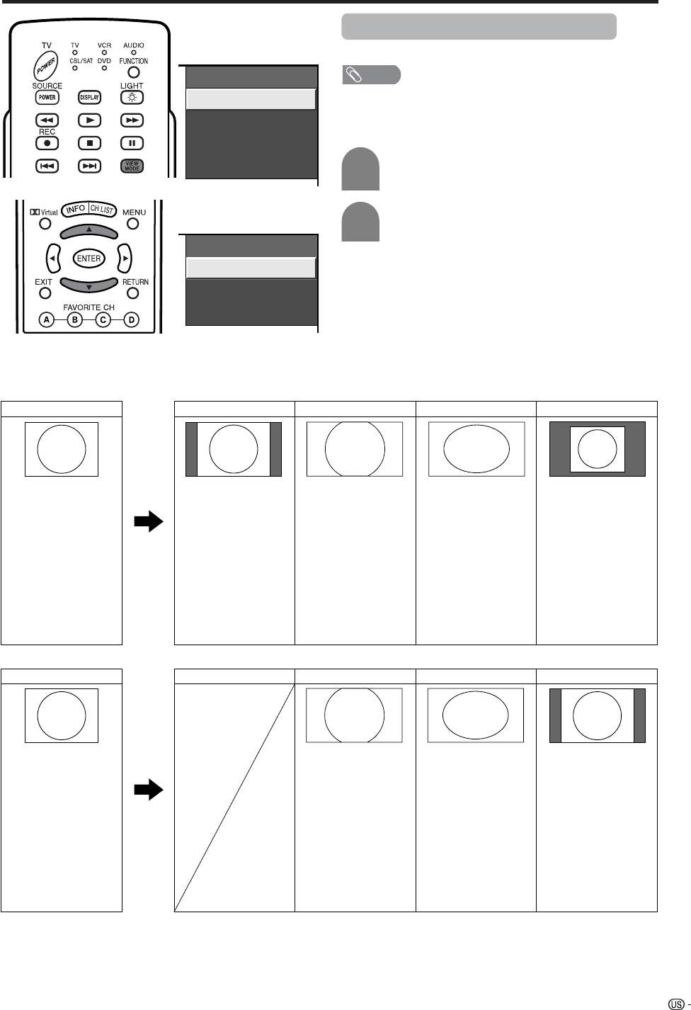
69
Useful adjustment settings
Input signal
(1024m768)
Input signal
(640m480)
View mode (for PC input mode)
You can select the screen size.
a
View Mode
Normal
Stretch
Dot by Dot
Zoom
View Mode
Zoom
Dot by Dot
Stretch
Input signal Normal Zoom Stretch Dot by Dot
Input signal Normal Zoom Stretch Dot by Dot
ex. 640g480 Keeps the original
aspect ratio in a full
screen display.
Keeps the original
aspect ratio in a full
screen display. The
top and bottom of
the image is slightly
cropped.
An image fully fills
the screen.
Detects the
resolution of the
signal and
displays an image
with the same
number of pixels
on the screen.
1024g768 Keeps the original
aspect ratio in a full
screen display. The
top and bottom of
the image is slightly
cropped.
Detects the
resolution of the
signal and displays
an image with the
same number of
pixels on the
screen.
An image fully fills
the screen.
a
Screen size images.
NOTE
• Connect the PC before making adjustments. (See page
55.)
• Selectable screen size may vary with input signal type.
Press VIEW MODE.
• The View mode menu displays.
1
2
Press VIEW MODE or a/bto select a
desired item on the menu.
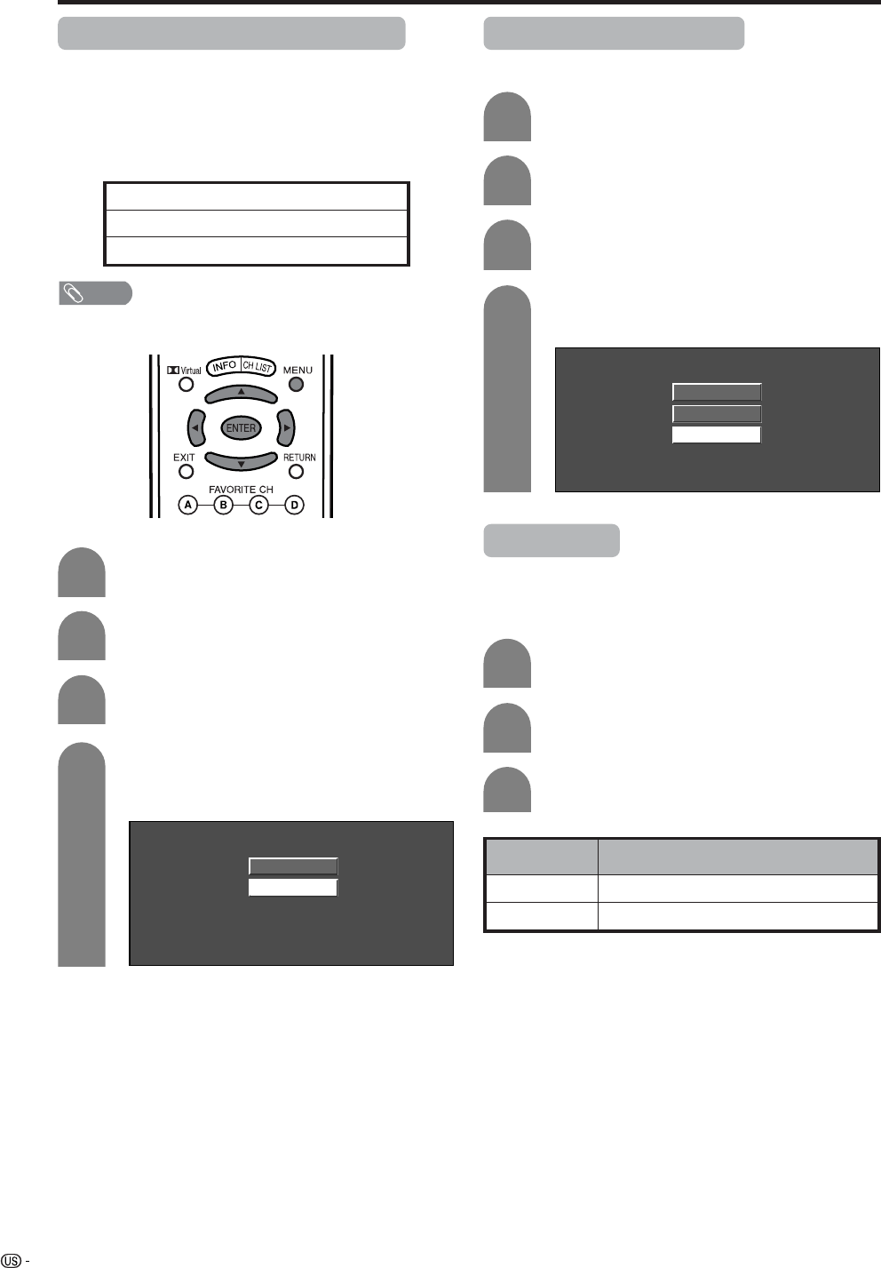
70
Useful adjustment settings
Press MENU and the MENU screen displays.
1
2
Press a/b to select “Input Signal” and then
press ENTER.
3
Press c/d to select “Setup”.
Press a/b to select the desired input signal
on the display.
4
640 x 480
848 x 480
Example
Input signal (for PC input mode)
• Some input signals may have to be registered manually
to display properly.
• The pairs of input signals (resolutions) in the list below
are not distinguishable when received. In such case, you
have to set the correct signal manually. After setting once,
it will display when the same signal (resolution) is input
again.
NOTE
• You can only select the “Input Signal” on the Setup menu
when receiving one of the 6 input signals listed above.
Digital Noise Reduction
Produces a clearer video image.
1
2
3
Press MENU and the MENU screen displays.
Press c/d to select “Option”.
Press a/b to select “Digital Noise
Reduction”, and then press ENTER.
Press a/b to select the desired level, and
then press ENTER.
4
Off
High
Low
720g400
848g480
1280g768
640g400
640g480
1024g768
Audio Only
When listening to music from a music program, you
can set the Liquid Crystal display off and enjoy audio
only.
Press c/d to select “On”, and then press
ENTER.
Repeat steps 1 and 2 in Digital Noise
Reduction.
Press a/b to select “Audio Only”, and then
press ENTER.
1
2
3
Description
Audio is output without screen image.
Both screen images and audio are output.
Selected item
On
Off
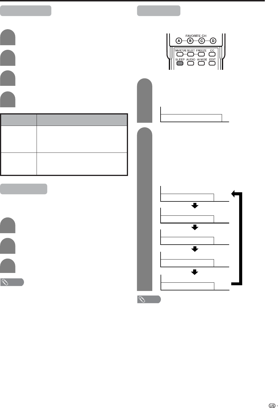
71
Useful adjustment settings
Description
• Sound via speaker is adjusted with VOL
k/l on the remote control unit or VOL l/
k on the Display.
• Sound via the MONITOR OUTPUT terminal
is not adjustable and constantly outputs.
• Sound via the MONITOR OUTPUT terminal
is adjusted with VOL k/l on the remote
control unit or VOL l/kon the Display.
• Sound via speaker is muted.
Selected item
Fixed
Variable
Output Select
Allows you to select what controls the audio output.
Press MENU and the MENU screen displays.
1
2
Press a/b to select “Output Select”, and
then press ENTER.
3
Press c/d to select “Fixed” or “Variable”,
and then press ENTER.
4
Press c/d to select “Option”.
Quick Shoot
Use Quick Shoot Operation to record action video more
clearly.
1
2
3
Repeat steps 1 and 2 in Output Select.
Press a/b to select “Quick Shoot”, and then
press ENTER.
Press c/d to select “On”, and then press
ENTER.
NOTE
• Quick Shoot may cause image noise. If this occurs turn
the function “Off”.
Sleep timer
Allows you to set a time when the TV automatically
switches to standby.
Sleep Timer: Off
30
60
90
120
Sleep Timer:
Sleep Timer:
Sleep Timer:
Sleep Timer:
1
2
Press SLEEP.
• Remaining time displays when sleep timer has
been set.
Each time you press SLEEP, the remaining
time switches as shown below.
• When set, the time automatically starts counting
down.
• If you want to adjust the sleep timer, you can
press SLEEP twice then change the time
setting.
• Five minutes before time expires, the remaining
time displays each minute.
NOTE
• Select “OFF” by pressing SLEEP to cancel the sleep timer.
• If the sleep timer is activated when set to zero, the TV will
enter STANDBY mode.
Sleep Timer: Remaining 30

72
Title Display Type
Select the CH display for Digital broadcasting.
1
2
4
3
Press MENU and the MENU screen displays.
Press c/d to select “Setup”.
Press a/b to select “Title Display Type”, and
then press ENTER.
Press c/d to select "On" or "Off", and then
press ENTER.
Selected item Descroption
On
Off
"Channel call" displays
"Channel call" does not display
Useful adjustment settings
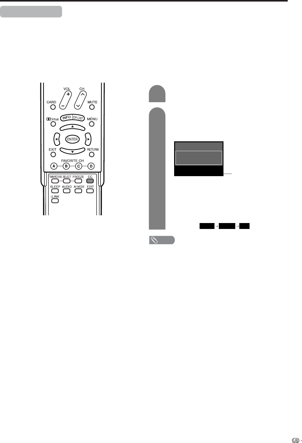
73
Useful adjustment settings
Closed caption
• Your TV is equipped with an internal closed caption decoder. Closed caption is the system which allows you
to view conversations, narration, and sound effects in TV programs and home videos as subtitles on your
Display.
• Not all programs and videos offer closed caption. Please look for the “N” symbol to ensure that captions will
be shown.
• “CC1” or “CC2” displays subtitles of TV dramas and news programs while allowing a full view of the picture.
• “Text1” or “Text2” superimposes on the picture other information (e.g. TV guide, weather) that is independent
of the TV in progress.
2
ANALOG-A Air
Audio : MONO
CC : 1/2 CC1
NOTE
• See page 74 to 76 for the detailed closed caption settings.
• When using Twin Picture functions (see page 86), Closed
Caption the program on the active screen will be
displayed.
• When using Freeze functions, closed caption will not be
displayed on the right screen (still image).
• When the program contains no closed caption, “ ––”
displays in the closed caption information.
• Four kinds of closed caption service(CC1, CC2, Text1,
Text2) are available. However, selectable service(CC1,
CC2, Text1, Text2) are depends on the programs contains.
Closed caption
information
1
2
Press CC.
• Present Closed caption information displays.
Press CC while the Closed caption
information in still on the screen.
• You can sequentially select a closed caption
service which you prefer.
• Depending on the signal, information such as
1/4 or 1/2 will appear.
1/2 shows the first of two services.
Example:
When a program has two services (CC1 and
Text 1), closed caption will toggles like below.
1/2 CC1 2/2 Text1 OFF
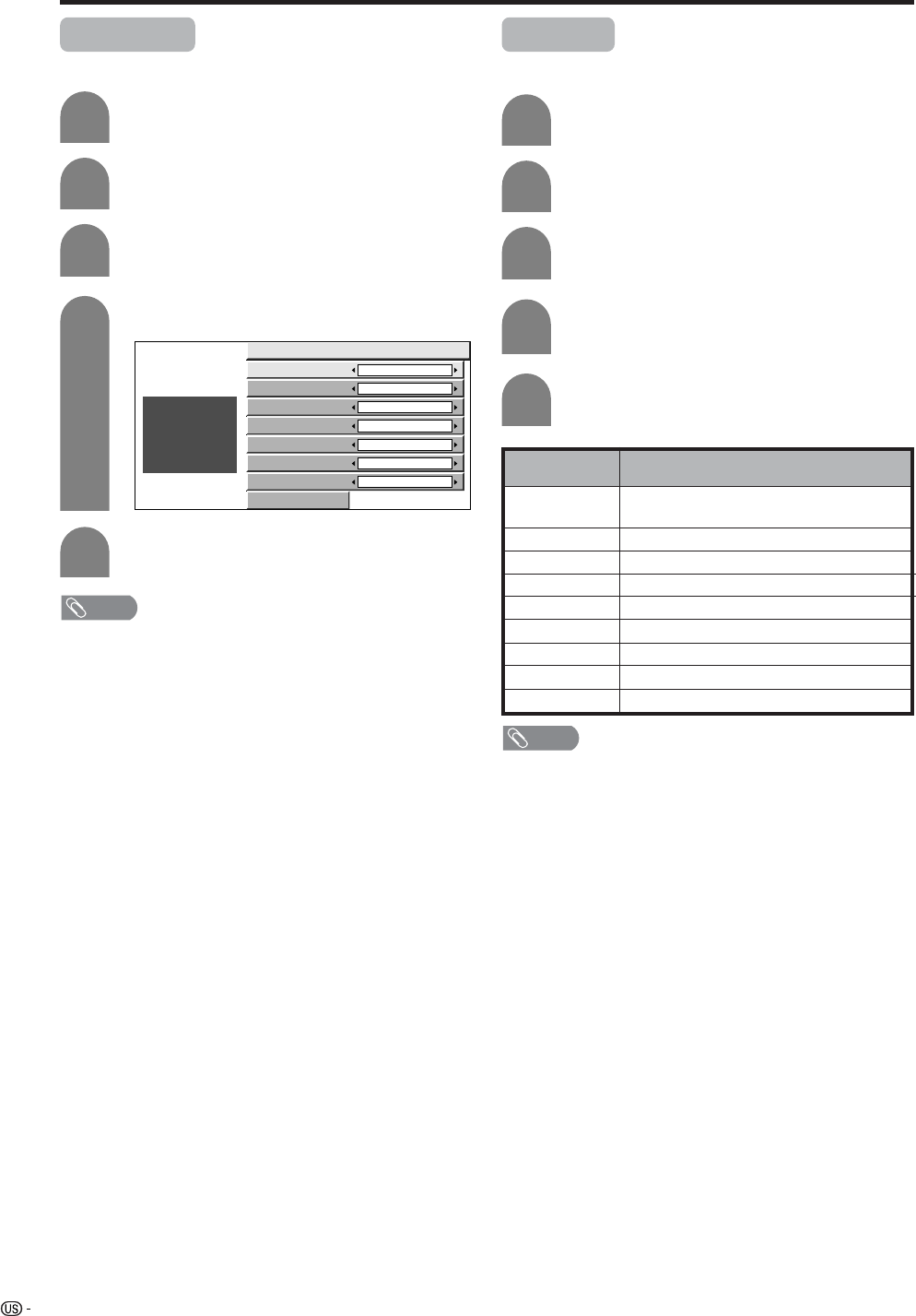
74
Useful adjustment settings
Caption Size
Select a caption size.
4
Press a/b to select “Caption Size”.
Press MENU and the MENU screen displays.
1
2
Press c/d to select “Option”.
3
Press a/b to select “Caption Setup”.
Caption Size Default
Font Style Default
Foreground Color Default
Foreground Opacity Default
Background Color Default
Background Opacity Default
Character Edge Default
Reset
ABC
123
Font Style
Select a font style.
Press a/b to select “Font Style”.
4
Press c/d to select the desired style.
5
Press MENU and the MENU screen displays.
1
2
Press c/d to select “Option”.
3
Press a/b to select “Caption Setup”.
5
Press c/d to select the desired size.
Description
The font specified by broadcasting station
or default font.
Proportional font used in the MENU screen.
Monospaced with serifs.
Proportionally spaced with serifs.
Monospaced without serifs.
Proportionally spaced without serifs.
Casual font type.
Cursive font type.
Small capitals.
Selected item
Default
Type 0
Type 1
Type 2
Type 3
Type 4
Type 5
Type 6
Type 7
NOTE
• Default: The caption size specified by broadcasting station
or default size.
• For resetting all adjustment items to the factory preset
values, press a/b to select “Reset”, and then press
ENTER.
NOTE
• For resetting all adjustment items to the factory preset
values, press a/b to select “Reset”, and then press
ENTER.
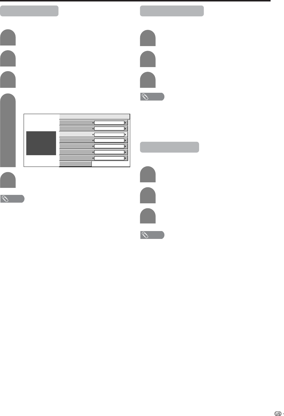
75
Useful adjustment settings
Foreground Color
Select a character foreground color.
4
Press a/b to select “Foreground Color”.
Press MENU and the MENU screen displays.
1
2
Press c/d to select “Option”.
3
Press a/b to select “Caption Setup”.
Caption Size Default
Font Style Default
Foreground Color Default
Foreground Opacity Default
Background Color Default
Background Opacity Default
Character Edge Default
Reset
ABC
123
Foreground Opacity
Select a foreground opacity value.
Press a/b to select “Foreground Opacity”.
Press c/d to select the desired value.
Repeat steps 1 to 3 in Foreground Color.
1
2
3
5Press c/d to select the desired color.
NOTE
• Default: The foreground color specified by broadcasting
station or default color.
• For resetting all adjustment items to the factory preset
values, press a/b to select “Reset”, and then press
ENTER.
NOTE
• Default: The foreground opacity value specified by
broadcasting station or default opacity value.
• For resetting all adjustment items to the factory preset
values, press a/b to select “Reset”, and then press
ENTER.
Background Color
Select a character background color.
Press a/b to select “Background Color”.
Repeat steps 1 to 3 in Foreground Color.
1
2
3
Press c/d to select the desired color.
NOTE
• Default: The background color specified by broadcasting
station or default color.
• For resetting all adjustment items to the factory preset
values, press a/b to select “Reset”, and then press
ENTER.
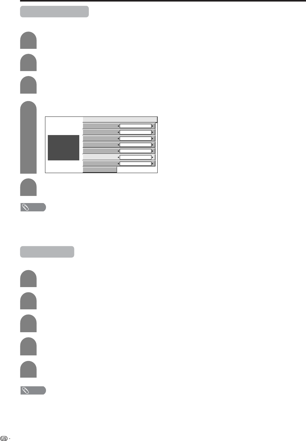
76
Useful adjustment settings
Background Opacity
Select a background opacity value.
Press a/b to select “Background Opacity”.
4
Press c/d to select the desired value.
5
Press MENU and the MENU screen displays.
1
2
Press c/d to select “Option”.
3
Press a/b to select “Caption Setup”.
Caption Size Default
Font Style Default
Foreground Color Default
Foreground Opacity Default
Background Color Default
Background Opacity Default
Character Edge Default
Reset
ABC
123
NOTE
• Default: The background opacity value specified by
broadcasting station or default opacity value.
• For resetting all adjustment items to the factory preset
values, press a/b to select “Reset”, and then press
ENTER.
Character Edge
Select a character edge.
4
Press a/b to select “Character Edge”.
Press MENU and the MENU screen displays.
1
2
Press c/d to select “Option”.
3
Press a/b to select “Caption Setup”, and
then press ENTER.
5
Press c/d to select the desired setting.
NOTE
• Default: The character edge specified by broadcasting
station or default edge.
• For resetting all adjustment items to the factory preset
values, press a/b to select “Reset”, and then press
ENTER.
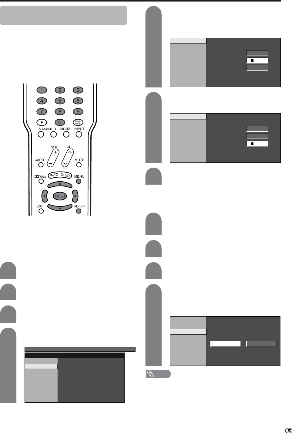
77
Useful adjustment settings
Secret number setting for parental
control (AV input mode only)
Allows you to use a secret number to protect certain
settings from being accidentally changed.
IMPORTANT:
Three conditions must be met to enable V-Chip (see
pages 79 to 83):
1Secret No. is registered.
2V-Chip settings have been made.
3“Status” is set to “On”.
Press MENU and MENU screen displays.
1
2
Press c/d to select “Setup”.
Press a/b to select “Parental CTRL”, and
then press ENTER.
3
Press a/b to select “Secret No.”, and then
press ENTER.
4
V-Chip
Secret No.
Status
TV MENU
[Setup ... Parental CTRL]
Select “New Secret No.”, and then press
ENTER.
Input the new 4-digit secret number by using
0 – 9.
5
New Secret No.
Secret No. Clear
New Secret No. ––––
Input Secret No. ––––
Reconfirm ––––
Input the same 4-digit number on the
“Reconfirm” screen as in step 5 to confirm.
6
New Secret No.
Secret No. Clear
New Secret No. ****
Input Secret No.
––––
Reconfirm
––––
Setting parental control status
Used to enable or disable the parental control function.
Press a/b to select “Status”, and then press
ENTER.
Press c/d to select “On” or “Off”, and then
press ENTER.
• Select “On” to enable and “Off” to disable
Parental CTRL.
V-Chip
Secret No.
Status
On Off
Repeat steps 1 to 3 in Setting a secret
number.
• Secret number setting menu displays.
1
2
Input the 4-digit secret number by using 0 –
9.
3
4
Press RETURN to start configuring V-Chip
settings. (See pages 80 and 82 for details.)
7
Setting a secret number
NOTE
• You can skip step 1 and 2 above while in Parental CTRL
screen.
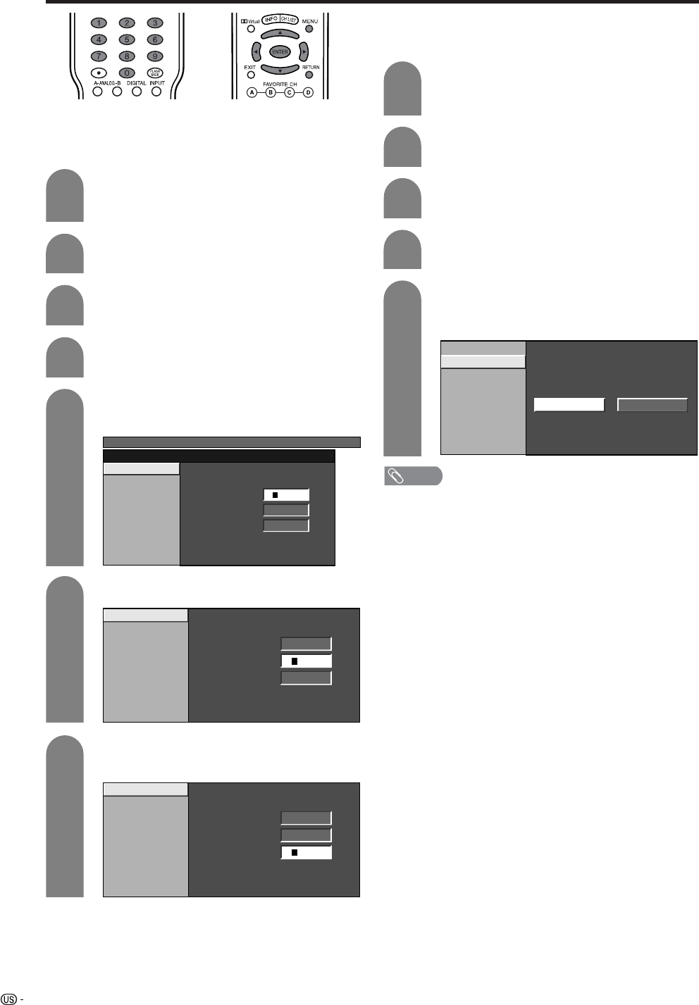
78
Useful adjustment settings
Changing the secret number
Allows you to change your current secret number.
Repeat steps 1 to 3 in Setting a secret
number.
• Secret number setting menu displays.
1
3
Press a/b to select “New Secret No.”, and
then press ENTER.
Input the old 4-digit number you have set
using 0 – 9.
MENU
[Setup ... Parental CTRL]
New Secret No.
Secret No. Clear
New Secret No. ––––
Input Secret No. ––––
Reconfirm ––––
Input the new 4-digit number using 0 – 9.
Input the same 4-digit number on the
“Reconfirm” screen as in step 6 to confirm.
Clearing the secret number
Allows you to clear your secret number.
Repeat steps 1 to 3 in Setting a secret
number.
• Secret number setting menu displays.
1
2
Input the 4-digit secret number by using 0 –
9.
3
5
4
Press a/b to select “Secret No.”, and then
press ENTER.
Press c/d to select “Yes”, and then press
ENTER.
• Your secret number is cleared.
Press a/b to select “Secret No. Clear”, and
then press ENTER.
NOTE
• See page 77 for re-registering with a new secret number
after being cleared.
•As a precautionary measure, make a note of your
secret number and keep it in a familiar place. If you
lose or forget your secret number, initialize the
Liquid Crystal Television to return all settings except
for the TV channel settings to factory preset values.
(See page 100.)
• If the secret number is cleared the Status setting
automatically sets to “Off”. “V-Chip” and “Status” will not
be selectable from the menu.
New Secret No.
Secret No. Clear
Yes No
Press a/b to select “Secret No.”, and then
press ENTER.
New Secret No.
Secret No. Clear
New Secret No. ––––
Input Secret No. ––––
Reconfirm ––––
4
5
6
7
New Secret No.
Secret No. Clear
New Secret No. ****
Input Secret No.
––––
Reconfirm
––––
2
Input the 4-digit secret number by using 0 –
9.
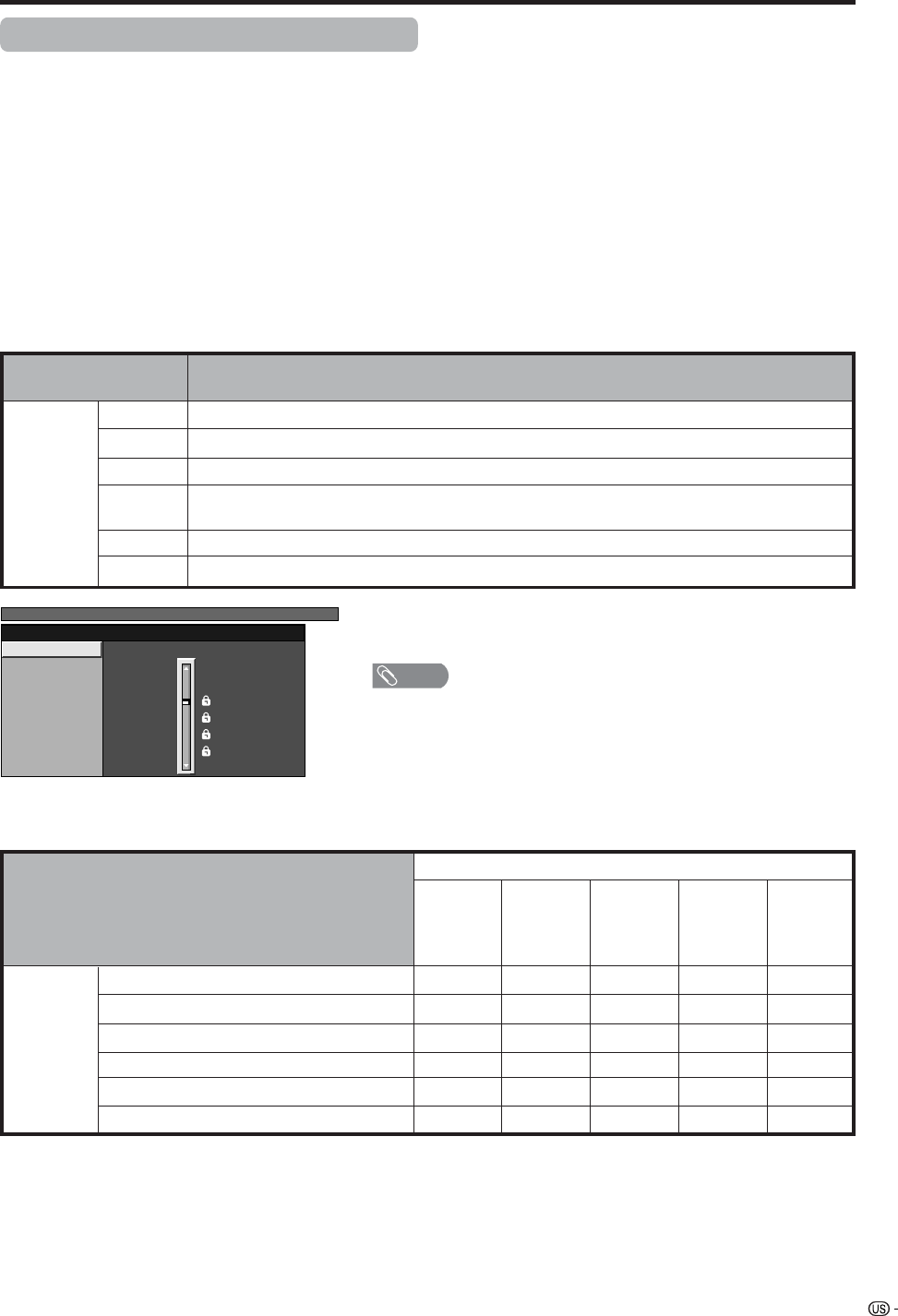
79
Useful adjustment settings
Parental control (setting V-CHIP level)
V-CHIP is an electronic filtering device built into your TV. This tool gives parents a great degree of control over
broadcasts accessed by their children. It allows parents to select programs judged suitable for child viewing
while blocking ones judged not suitable. It does so automatically once you activate the V-CHIP feature in your
Liquid Crystal Television.
“V-Chip” and “Status” will not be selectable from the menu if you do not first configure your secret
number. (See page 77 for Secret number setting for parental control.)
• The U.S. has two rating systems for viewing content: TV Parental Guidelines and movie ratings.
• The TV Parental Guidelines work in conjunction with the V-CHIP to help parents screen out inappropriate
television shows from their children.
• Movie ratings are used for original movies rated by the Motion Picture Association of America (MPAA) as
watched on cable TV and not edited for television. The V-CHIP can also be set to block MPAA-rated movies.
Voluntary movie rating system (MPAA)
Rating
Age
G
PG
PG-13
R
NC-17
X
General audiences. All ages admitted.
Parental guidance suggested. Some material may not be suitable for children.
Parents strongly cautioned. Some material may be inappropriate for children under 13.
Restricted. Under 17 requires accompanying parent or adult guardian (age varies in some
jurisdictions).
No one 17 and under admitted.
X is an older rating that is unified with NC-17 but may be encoded in the data of older movies.
Description
X: Content rating can be set.
TV Parental Guidelines
TV-Y (All children)
TV-Y7 (Directed to older children)
TV-G (General audience)
TV-PG (Parental Guidance suggested)
TV-14 (Parents strongly cautioned)
TV-MA (Mature audience only)
Rating
Suggested
age
Content
FV
(Fantasy
violence)
V
(Violence)
S
(Sexual
situation)
L
(Adult
language)
D
(Sexually
suggestive
dialog)
X
X
X
X
X
X
X
X
X
X
X
X
a
• If you select “PG-13”, this will automatically block the higher ratings
“R”, “NC-17” and “X”.
NOTE
• Voluntary movie rating system only uses an age-based rating.
MENU [Setup ... Parental CTRL]
MPAA
TV Guidelines
Can. English Ratings
Can. French Ratings PG-13
R
NC-17
X
NONE
PG
G
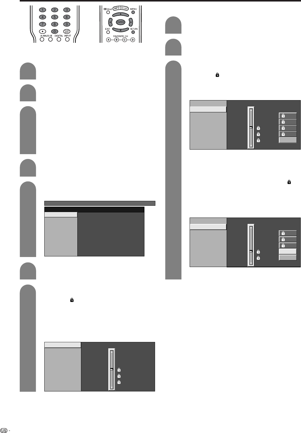
80
Useful adjustment settings
Voluntary movie rating system (MPAA)
Press MENU and the MENU screen displays.
1
2
Press c/d to select “Setup”.
Input the 4-digit secret number by using 0 –
9.
3
Press a/b to select “Parental CTRL”, and
then press ENTER.
• Secret number setting menu displays only
when “Secret No.” is set. (See page 77.)
• “V-Chip” and “Status” will not be selectable
from the menu if you do not first configure your
secret number. (See page 77.)
5
Press a/b to select “V-Chip”, and then press
ENTER.
6
V-Chip
Secret No.
Status
MENU [Setup ... Parental CTRL]
Press a/b to select “MPAA”, and then press
ENTER.
Press a/b to adjust the item to your desired
position. “ ” indicates the item is blocked.
Press RETURN.
• The setting automatically enters “Block” for any
ratings below your selection.
• If Status is not set to “On” the configuration
settings will not work. (See page 77.)
7
MPAA
TV Guidelines
Can. English Ratings
Can. French Ratings PG-13
R
NC-17
X
NONE
PG
G
TV Parental Guidelines (TV Guidelines)
Repeat steps 1 to 5 in Voluntary movie
rating system (MPAA).
1
2
Press a/b to select “TV Guidelines”, and
then press ENTER.
Press a/b to adjust the item to your desired
position. “ ” indicates the item is blocked.
• The setting automatically enters “Block” for any
ratings below your selection.
3
MPAA
TV Guidelines
Can. English Ratings
Can. French Ratings L
S
V
D
TV-G
TV-PG
TV-14
TV-MA
NONE
TV-Y7
TV-Y
When setting an individual content-based rating
item, do as follows:
1Press d to access block content items from
the currently selected age-based rating item.
2Press a/b to select an individual item, and
then press ENTER to unblock (“ ” is
removed). Repeat the same steps for other
items.
3Press c or RETURN to register after all
individual content rating items are set.
MPAA
TV Guidelines
Can. English Ratings
Can. French Ratings L
S
V
D
TV-G
TV-PG
TV-14
TV-MA
NONE
TV-Y7
TV-Y
4
Example
Example
Example
• If Status is not set to “On” the configuration
settings will not work. (See page 77.)
81
Useful adjustment settings
Canadian Rating Systems
• The TV rating systems in Canada are based on the Canadian Radio-Television and Telecommunications
Commission (CRTC) policy on violence in television programming.
• While violence is the most important content element to be rated, the structure developed takes into
consideration other program content like language, nudity, sexuality and mature themes.
• When setting the V-CHIP on the Canadian system you can choose either the Canadian English ratings or the
Canadian French ratings.
Rating
Age
E
C
C8e
G
PG
14e
18e
Exempt: Includes news, sports, documentaries and other information programming; talk
shows, music videos, and variety programming.
Children: Intended for younger children under the age of 8 years. Pays careful attention to
themes that could threaten their sense of security and well-being.
Children over 8 years old: Contains no portrayal of violence as the preferred, acceptable,
or only way to resolve conflict; nor encourage children to imitate dangerous acts which
they may see on the screen.
General: Considered acceptable for all age groups. Appropriate viewing for the entire
family, contains very little violence, physical, verbal or emotional.
Parental Guidance: Intended for a general audience, but may not be suitable for younger
children (under the age of 8) because it could contain controversial themes or issues.
Over 14 Years: Could contain themes where violence is one of the dominant elements of
the storyline, but it must be integral to the development of plot or character. Language
usage could be profane and nudity present within the context of the theme.
Adults: Intended for viewers 18 years and older and might contain depictions of violence,
which while related to the development of plot, character or themes, are intended for adult
viewing. Could contain graphic language and portrayals of sex and nudity.
Description
Canadian English ratings
Rating
Age
E
G
8anse
13anse
16anse
18anse
Exempt programming.
General: All ages and children, contains minimal direct violence, but may be integrated
into the plot in a humorous or unrealistic manner.
General but inadvisable for young children: May be viewed by a wide public audience, but
could contain scenes disturbing to children under 8 who cannot distinguish between
imaginary and real situations. Recommended for viewing with parent.
Over 13 years: Could contain frequent violent scenes and therefore recommended for
viewing with parent.
Over 16 years: Could contain frequent violent scenes and intense violence.
Over 18 years: Only for adult viewing. Could contain frequent violent scenes and extreme
violence.
Description
Canadian French ratings
82
Useful adjustment settings
Canadian English ratings
Press a/b to select “Can. English Ratings”,
and then press ENTER.
Press a/b to adjust the item to your desired
position. “ ” indicates the item is blocked.
• The setting automatically enters “Block” for any
ratings below your selection.
• If Status is not set to “On” the configuration
settings will not work. (See page 77.)
MPAA
TV Guidelines
Can. English Ratings
Can. French Ratings
E
C
C8+
G
PG
14+
18+
NONE
Canadian French ratings
Repeat steps 1 to 5 in Canadian English
ratings.
1
2
Press a/b to select “Can. French Ratings”,
and then press ENTER.
Press a/b to adjust the item to your desired
position. “ ” indicates the item is blocked.
• The setting automatically enters “Block” for any
ratings below your selection.
• If Status is not set to “On” the configuration
settings will not work. (See page 77.)
3
MPAA
TV Guidelines
Can. English Ratings
Can. French Ratings 8ans+
13ans+
16ans+
18ans+
NONE
G
E
Press MENU and the MENU screen displays.
1
2
Press c/d to select “Setup”.
Input the 4-digit secret number by using 0 –
9.
3
MENU [Setup ... Parental CTRL]
Setup Option
Secret No. ––––
Press a/b to select “Parental CTRL”, and
then press ENTER.
• Secret number setting menu displays only
when “Secret No.” is set. (See page 77.)
• “V-Chip” and “Status” will not be selectable
from the menu if you do not first configure your
secret number. (See page 77.)
5
Press a/b to select “V-Chip”, and then press
ENTER.
6
V-Chip
Secret No.
Status
4
Example
Example
7
83
Useful adjustment settings
How to temporarily release the V-CHIP
BLOCK
• The V-CHIP BLOCK is working and censors a
broadcast, “V-CHIP HAS BEEN ACTIVATED.”
displays.
Reactivating the temporarily released
V-CHIP BLOCK
• You can reactivate the temporarily released V-CHIP
BLOCK as shown below.
Method 1:
Select “Status” setting from the Parental CTRL menu
to reactivate BLOCK. See page 77.
Method 2:
Select “V-Chip” setting (“MPAA”, “TV Guidelines”,
“Can. English Ratings” or “Can. French Ratings”)
from the Parental CTRL to reactivate BLOCK. See
pages 80 and 82.
Method 3:
Switch off the TV power.
NOTE
• Performing any of the three above will activate the V-CHIP
BLOCK.
1
2
Press ENTER while the V-CHIP is working
and then the secret number setting menu
displays.
Enter your 4-digit secret number with 0 – 9
and then press ENTER. At this time V-CHIP
BLOCK temporarily releases.
84
Useful adjustment settings
Center Channel Input
You can use the display speakers as center speaker when using 5.1ch surrounding sound system.
4
Press c/d to select “On” , and then press
ENTER.
Press MENU and the MENU screen displays.
1
2
Press c/d to select “Option”, and then press
ENTER.
3
Press a/b to select “Center Channel Input”,
and then press ENTER.
OffOn
NOTE
• Sound from Center Channel Input terminal is output from
the display speaker.
Display speaker
* Connect to external audio equipment
which supports 5.1ch surround sound
system.
Refer to your external equipment
operation manual for details.
85
Other viewing options
Viewing a list of Digital broadcast
channels
You can view a list of all currently watchable digital
broadcast channels.
Push CH LIST while watching a digital
broadcast.
• A list of all digital channels (over-the-air or
cable) currently watchable will be displayed.
Press a/b to select the channel you want
to watch, and then press ENTER to display
the selected channel.
Press c/d to scroll between pages of the
Channel List.
NOTE
• Sometimes the name of the program is not broadcast. In
that case, the program name will not be displayed.
1
2
3
WGBH-SD
CH LIST
[DTV-Air]
PBS-HD
WGBH-DX
2.1
2.2
2.10
Air/Cable
Broadcast
station
CH.
Number
(Example) Channel List Screen for Over-the-
Air Broadcasts
Viewing information of the program
You can view information about a digital broadcast you
are currently watching.
Press INFO while watching a digital
broadcast.
• Information of the current program will be
displayed.
1
WGBH-SD
WGBH DTV Broadcast Signal
Input Info.
Video
Audio
C.C.
Rating
480i
Stereo
Optic.
i.Link
REC
REC
OK
OK
- -
- -
Broadcast station
Program
Program information
Sample program information
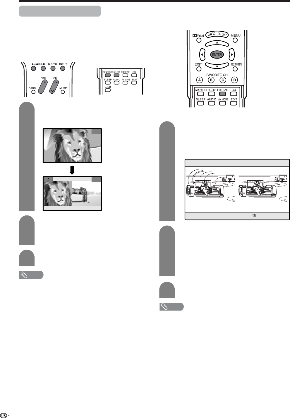
86
Other viewing options
Twin picture functions
Allows you to display two pictures on the screen at
one time.
Twin picture in all cases
You can display two same-sized pictures except when
inputting from INPUT 4 (HDMI) and INPUT 5 (DVI-I)
terminals and CARD.
Press TWIN PICTURE.
• Twin picture displays and a selected input
source image displays.
Press SELECT to set either screen to be
active.
•“z” displays on the active screen, which has
sound output.
Press TWIN PICTURE to exit twin picture.
NOTE
• This function does not work under the following input
conditions:
1INPUT 4 (HDMI)
2INPUT 5 (DVI-I)
3CARD
4Two pictures from the same source (e.g. INPUT 1 and
INPUT 1)
5An image will appear on the right side only if it is a 480i
signal.
*An SDTV image has a 480p signal, so it will not appear
either.
• When this function is not available, “No dual screen display
available” will display.
• Pressing ANALOG-A, B, DIGITAL while viewing in Twin
Picture mode (TV image and video image) with TV selected
will display the TV image of the other tuner.Picture and
still image
Picture and still image
You can display two same-sized pictures – one moving
and one still.
Press FREEZE.
• A moving image displays on the left screen and
a still image displays on the right screen. The
still image is one frame captured from a moving
image at the moment you press FREEZE.
Update the still image by pressing ENTER.
• Each time you press ENTER, the image on the
right screen updates.
• If a PC card with enough capacity is inserted
in the system, a message will appear on the
screen asking you whether to save the image.
Press REC on the remote control if you want to
save. (See page 44.)
Press FREEZE to exit still image.
NOTE
• This function does not work in INPUT 4 (HDMI), INPUT 5
(DVI-I) and CARD.
• When this function is not available, “No displaying still
image” will display.
• Another image can be saved if a PC card with enough
capacity is inserted in the system.
• The still image is automatically erased after 30 minutes.
• If you are using FREEZE and a broadcast activates the V-
CHIP BLOCK, FREEZE will cancel and a block message
will appear.
FREEZE
1
2
3
1
2
3
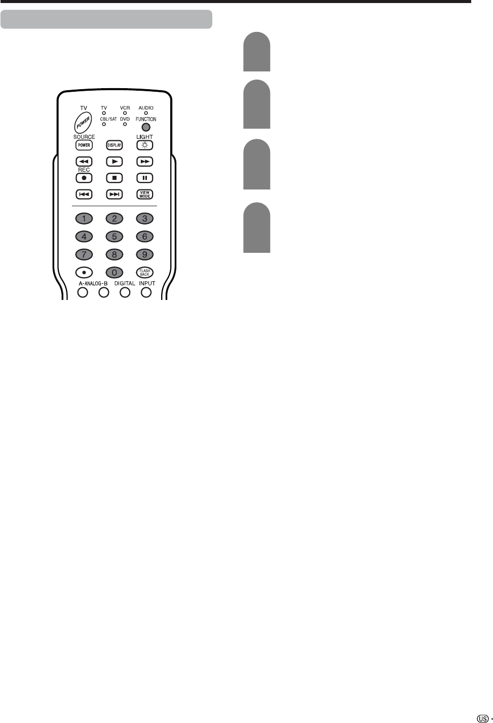
87
Other viewing options
Presetting remote control function
You can operate the connected AV products (AV
Receiver, Cable Box, SAT tuner, DTV, VCR, DVD, LD)
using the presetting manufacturer function for your
remote control unit.
Presetting manufacturer codes
Press FUNCTION until the LED for your
device lights up.
After the LED for your device lights up, if you
press FUNCTION for three seconds and
enter the code registration mode, the LED
will blink.
Press 0 – 9 to enter the manufacturer code.
(See page 88.)
• Preset mode is finished once the LED no longer
lights up.
1
2
3
After registering the code, the LED will stop
blinking then turn off after one second. (If
you perform an incorrect operation, the LED
will blink quickly then turn off.)
4
88
Other viewing options
Manufacturer codes
Akai
Audio
Broksonic
Canon
Capehart
Craig
Curtis Mathis
Daewoo
DBX
Dynatech
Emerson
Fisher
Funai
G.E.
Goldstar
Hitachi
Instant Replay
JC Penney
JVC
Kenwood
Lloyds
Magnavox
Magnin
Marantz
Memorex
Minolta
Mitsubishi
Montgomery Ward
Multitech
NEC
Panasonic
Pentax
Philco
Philips
RCA
Realistic
Samsung
Sanyo
Scott
Sears
Sharp
Shintom
Sony
Sound Design
Sylvania
Symphonic
Tatung
Teac
Teknika
Thomas
TMK
Toshiba
Video Concepts
Yamaha
Zenith
25, 26, 37
15, 22, 30
32
04
34
10, 31
04
34
15, 22, 30
29
21, 32, 35
09, 10, 11
28, 29
04
24
06, 47
04
04, 06, 24, 30
15, 41, 42, 53
14, 15
29
04, 05, 08
31
30
04, 10, 24, 29
06
17, 18, 39, 40
02, 43
29
15, 22, 30
44, 45
05, 06
05
05, 08
06, 07, 33, 51
01, 02, 10, 24
23, 31
10, 14, 52
20
06, 11, 24
01, 02, 03
36
12, 13, 38
29
05, 08
29
15
15, 29
27, 29
29
21
19, 20
30
15, 29, 30
16
VCR BRAND REMOTE CONTROL
CODE NUMBER
Denon
JVC
Kenwood
Magnavox
Marantz
Mitsubishi
Panasonic
Philips
Pioneer
Proscan
RCA
Samsung
Sharp
Sony
Toshiba
Yamaha
Zenith
02
09, 13
21
04
04
06
02, 22
04, 23
08, 11, 20
03
03, 24
07, 12
01, 10
05, 25
04
02
04
DVD/LD BRAND REMOTE CONTROL
CODE NUMBER
Anvision
Cable Star
Eagle
General Instrument
Jerrold
Magnavox
Oak Sigma
Panasonic
Philips
Pioneer
Randtek
RCA
Scientific Atlanta
Sony
Viewstar
Zenith
04, 05
04, 05
05
02, 03, 07, 12, 13, 14,
19, 22
02, 03, 07, 12, 13, 14,
19, 22, 31, 32, 33, 34,
35, 36, 37, 38, 39, 40
04, 05, 09, 14, 17, 18,
20, 21, 24, 25
8
16, 23
04, 05, 09, 15, 17, 18,
20, 21, 24, 25
08, 10, 29, 30, 46
04, 05
16, 27, 44, 45
01, 26
28
04, 05, 09, 15, 17, 18,
20, 21, 24, 25
06, 14
CATV CONVERTER
BRAND REMOTE CONTROL
CODE NUMBER
Sharp 01
AUDIO BRAND REMOTE CONTROL
CODE NUMBER
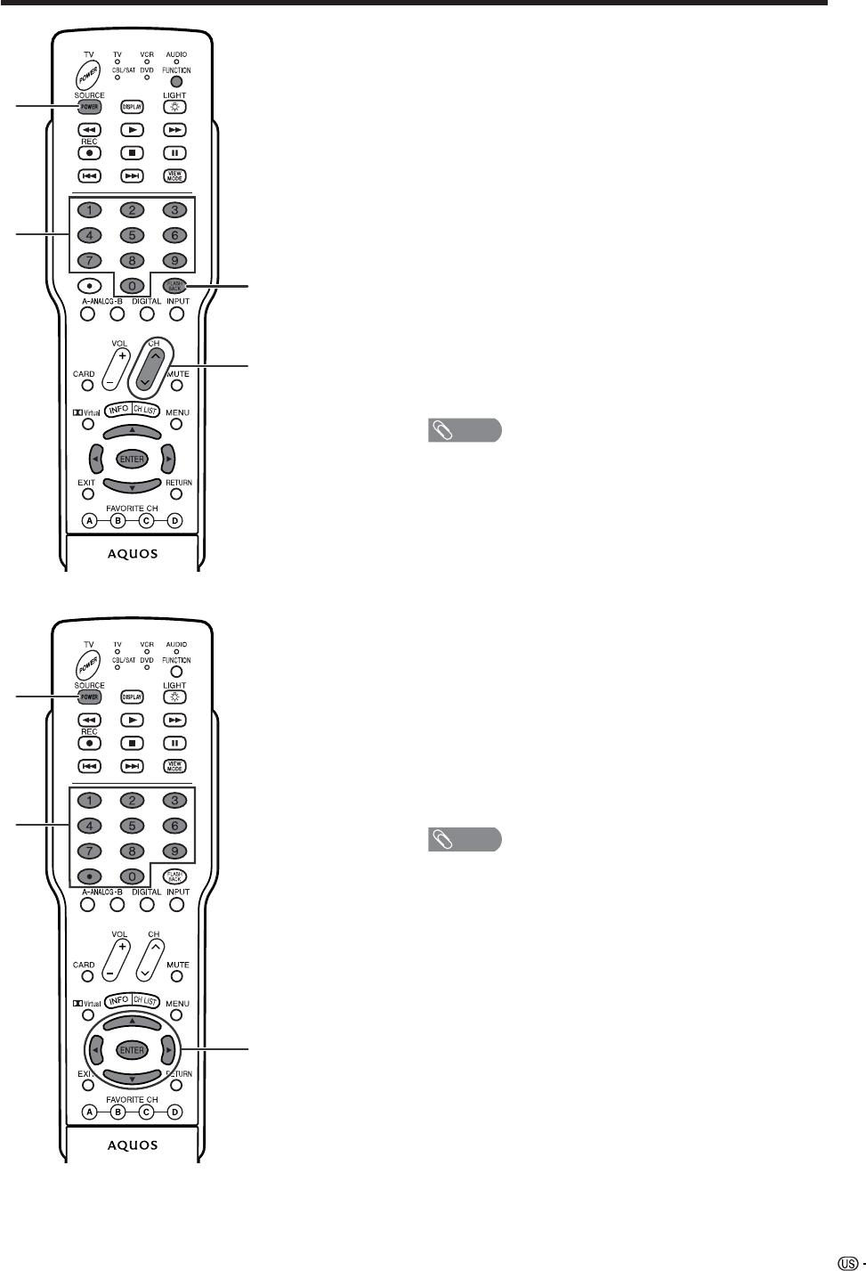
89
Other viewing options
Cable control buttons
When the FUNCTION is set to CBL/SAT the cable
converter connected to the Display can operate using
1 to 4.
1 SOURCE POWER
Turns the cable converter power on and off.
20 – 9
Press a button (or buttons) that corresponds to the
channel that you wish to watch.
3 FLASHBACK *
Press to switch between the current channel and the
channel you were watching immediately before.
4 CH a/b
Press CH aor CH bto tune in a higher or lower
channel.
*Some manufacturers do not preset FLASHBACK.
NOTE
• CABLE and SAT cannot be selected at the same time.
1
2
3
4
1
2
3
SAT control buttons
1 SOURCE POWER
Turns the Satellite broadcast tuner power on and off.
20 – 9, •(DOT)
Press a button (or buttons) that corresponds to the
channel that you wish to watch.
3 ENTER, a/b/c/d
ENTER: Press to activate the selected function.
a/b/c/d: Press the button to select items on the SAT
GUIDE screen or SAT MENU screen.
NOTE
• CABLE and SAT cannot be selected at the same time.
90
Other viewing options
VCR control buttons
The remote control unit button will function as follows
when the FUNCTION of the remote control unit is set
to VCR.
• When the input selector button having the same
number as the input terminal connecting the VCR is
pressed, the VCR can operate using 1 to 8.
1 CH a/b
Press to select the channel of the TV tuner on the VCR.
2 SOURCE POWER
Turns the power of the VCR on and off.
3F
Sets pauses and still pictures.
4G
Rewinds the tape and allows picture search.
5H
Stops the tape transport.
6 REC
Starts recording.
7J
Rapidly advances the tape and allows picture search.
8I
Starts playback.
2
4
65
7
8
3
1
91
Other viewing options
DVD control buttons
The remote control unit button will function as follows
when the FUNCTION of the remote control unit is set
to DVD.
• When the input selector button having the same
number as the input terminal connecting a DVD
player is pressed, these players can operate using
1 to 10.
1U
Pressing quickly once takes you to the start of the next
chapter. Each time you press it, you move ahead to the
start of the next chapter.
2T
Pressing quickly once takes you to the start of the
chapter currently playing. Each time you press it, you
move back to the start of the previous chapter.
3 SOURCE POWER
Turns the power of the DVD player on and off.
4F
Sets pauses and still pictures.
5G
Continue pressing to go backward.
6H
Playback stops when pressing once.
With some DVD players, pressing the button twice may
open the disc tray.
7 MENU
When this button is pressed, the DVD menu will display.
8 ENTER, a/b/c/d
ENTER: Press to activate the selected function.
a/b/c/d: Press the button to select items on the DVD
MENU screen.
9J
Continue pressing for fast forward.
10 I
Starts playback.
3 10
5
6
2
8
1
7
4
9

92
Appendix
• No power
• Unit cannot be operated.
• Remote control unit does not
operate.
• Picture is cut off/with sidebar
screen.
• When playing back video in card
mode, a part of the image is
missing or the image is out of
position.
• Strange color, light color, or color
misalignment
• Power is suddenly turned off.
• No picture
• No sound
• The upgrade screen will continue
to be displayed indefinitely.
Alternatively, it may appear and
disappear repeatedly.
Problem Possible Solution
• Check if you pressed TV POWER on the remote control unit. (See page 20.)
If the indicator on the Display lights up red, press TV POWER on the remote
control unit.
• Is the AC cord disconnected? (See page 10.)
• Has the main power been turned on? (See page 20.)
• External influences such as lightning, static electricity, may cause improper
operation. In this case, operate the unit after first turning on the power of the
Display or unplugging the AC cord and replugging it in after 1 or 2 minutes.
• Is the FUNCTION set correctly? Set it to the TV setting position.
• Are batteries inserted with polarity (e, f) aligned? (See page 13.)
• Are batteries worn out? (Replace with new batteries.)
• Are you using it under strong or fluorescent lighting?
• Is a fluorescent light illuminated near the remote control sensor?
• Is the image position correct? (See page 62.)
• Are screen mode adjustments such as picture size made correctly? (See pages
68 and 69)
• The video playback setting has been affected as a result of moving the image
position when playing back a still image in card mode.
It is recommended not to move the image position when playing back images
from a card.
• Adjust the picture tone. (See pages 31 to 34.)
• Is the room too bright? The picture may look dark in a room that is too bright.
• Check the input signal setting. (See page 66.)
• Is the sleep timer set? (See page 71.)
• Check the power control settings. (See page 36.)
• The unit’s internal temperature has increased.
Remove any objects blocking vent or clean the vent.
• Is connection to other components correct? (See pages 51 to 57.)
• Is correct input signal source selected after connection? (See page 66.)
• Is the correct input selected? (See page 66.)
• Is a non-compatible signal being input? (See page 93.)
• Is picture adjustment correct? (See pages 31 to 34.)
• Is “On” selected in “Audio Only”? (See page 70.)
• Is the volume too low? (See page 23.)
• Is “Variable” selected in “Output Select”? (See page 71.)
• Is “On” selected in “Center Channel Input”? (See page 84.)
• Is the cable antenna connected? Remove the CableCARD, reconnect the Antenna
correctly, and then reinsert the CableCARD. If the problem is still not resolved,
contact your cable company.
Troubleshooting
Cautions regarding use in high and low temperature environments
• When the unit is used in a low temperature space (e.g. room, office), the picture may leave trails or appear slightly
delayed. This is not a malfunction, and the unit will recover when the temperature returns to normal.
• Do not leave the unit in a hot or cold location. Also, do not leave the unit in a location exposed to direct sunlight or near
a heater, as this may cause the cabinet to deform and the Liquid Crystal panel to malfunction.
Storage temperature: –4°F to +140°F (–20°C to +60°C)
93
Appendix
PC compatibility chart
Apple and Macintosh are registered trademarks
of Apple Computer, Inc.
DDC is a registered trademark of Video Electronics
Standards Association.
Power Management is a registered trademark of
Sun Microsystems, Inc.
VGA and XGA are registered trademarks of
International Business Machines Co., Inc.
PC/MAC Resolution Horizontal Frequency Vertical Frequency VESA Standard
PC 31.5 kHz
37.9 kHz
31.5 kHz
37.9 kHz
31.5 kHz
37.9 kHz
37.5 kHz
43.3 kHz
31.5 kHz
35.1 kHz
37.9 kHz
48.1 kHz
46.9 kHz
53.7 kHz
48.4 kHz
56.5 kHz
60.0 kHz
68.7 kHz
45.0 kHz
48.1 kHz
64.0 kHz
34.9 kHz
49.7 kHz
60.2 kHz
640 x 400
720 x 400
VGA
640 x 480
WVGA 848 x 480
SVGA
800 x 600
1024 x 768XGA
1280 x 720
WXGA 1280 x 768
SXGA 1280 x 1024
VGA 640 x 480
MAC13"
XGA 1024 x 768
MAC19"
SVGA 832 x 624
MAC16"
60 Hz
85 Hz
60 Hz
85 Hz
60 Hz
72 Hz
75 Hz
85 Hz
60 Hz
56 Hz
60 Hz
72 Hz
75 Hz
85 Hz
60 Hz
70 Hz
75 Hz
85 Hz
60 Hz
60 Hz
60 Hz
67 Hz
75 Hz
75 Hz
O
O
O
O
O
O
O
O
O
O
O
O
O
O
O
O
94
RS-232C port specifications
Return codeCommand 4-digits Parameter 4-digits
PC Control of the System
• When a program is set, the Display can be controlled from the PC using the RS-232C terminal.
The input signal (PC/AV) can be selected, the volume can be adjusted and various other adjustments and
settings can be made, enabling automatic programmed playing.
•Attach an RS-232C cable cross-type (commercially available) to the supplied Din/D-Sub RS-232C for the
connections.
NOTE
• This operation system should be used by a person who is accustomed to using computers.
Communication conditions
Set the RS-232C communications settings on the PC to match the display’s communications conditions.
The Display’s communications settings are as follows:
Baud rate:
Parity bit:
Data length:
Stop bit:
Flow control:
9,600 bps
8 bits
None
1 bit
None
Appendix
Command format
Communication procedure
Send the control commands from the PC via the RS-232C connector.
The display operates according to the received command and sends a response message to the PC.
Do not send multiple commands at the same time. Wait until the PC receives the OK response before sending
the next command.
Eight ASCII codes e CR
Command 4-digits:Command. The text of four characters.
Parameter 4-digits:Parameter 0 – 9, x, blank, ?
Parameter
Input the parameter values, aligning left, and fill with blank(s) for the remainder. (Be sure that 4 values are input for the
parameter.)
When the input parameter is not within an adjustable range, “ERR” returns. (Refer to “Response code format”.)
Any numerical value can replace the “x” on the table.
When “?” is input for some commands, the present setting value responds.
C1 C2 C3 C4 P1 P2 P3 P4
0055
100
⫺30
0009
0
????
?
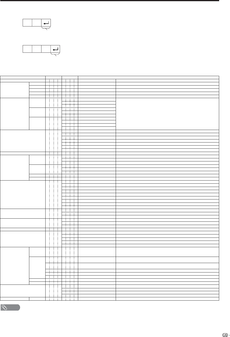
95
Command table
• Commands not indicated here are not guaranteed to operate.
CONTROL ITEM COMMAND
PARAMETER
CONTROL CONTENTS
POWER SETTING It shifts to standby.
It input-switches by the toggle. (It is the same as an input change key)
It input-switches to TV. (A channel remains as it is. (Last memory))
It input-switches to INPUT1~INPUT5.
It input-switches to i.LINK.
It shifts to CARD mode.
An input change is also included.
Although it can choose now, it is toggle operation in inside.
Although it can choose now, it is toggle operation in inside.
(Toggle)
Input terminal number (1–5)
AUTO
VIDEO
COMPONENT
DIGITAL PC
ANALOG PC
DIGITAL AV
ANALOG AV
(Toggle)
STANDARD
MOVIE
USER
GAME
DYNAMIC (Fixed)
DYNAMIC
Volume (0–60)
AV mode. (Ⳳ10)
PC mode. (0–180)
AV mode. (Ⳳ20)
PC mode. (0–100)
Only PC mode. (0–180)
Only PC mode. (0–40)
(Toggle) [AV]
An input change is included if it is not TV display.
In Air, 2–69ch is effective.
In Cable, 1–125ch is effective.
If it is not TV display, it will input-switch to TV. same function as CH+
If it is not TV display, it will input-switch to TV. same function as CH-
Toggle operation of a closed caption.
(Toggle)
Side Bar [AV]
S.Stretch [AV]
Zoom [AV]
Stretch [AV]
Normal [PC]
Zoom [PC]
Stretch [PC]
Dot by Dot [PC]
On
Off
OFF
OFF TIMER – 30 MIN.
The channel number of TV
The channel number of TV Ⳮ1
The channel number of TV ⳮ1
(Toggle)
(1–125)
AUTO
POWR
ITGD
ITVD
IAVD
ICRD
INP1
INP5
INPUT SELECTION A TOGGLE
i.LINK
INPUT SELECTION B
AV MODE SELECTION
VOLUME
POSITION
VIEWMODE
Dolby Virtual
SLEEP TIMER
CHANNEL
ANTENA SELECT
CC
DIRECT
(ANALOG)
(DIGITAL)
CH UP
CH DOWN
CHANNEL
H-POSITIONH-POSITION
V-POSITION
CLOCK
PHASE
INPUT 1
INPUT 5
AVMD
VOLM
HPOS
VPOS
CLCK
PHSE
ACDV
OFTM
DCCH
CHUP
CHDW
CLCP
WIDE
0
x
0
*
x
0
5
6
7
8
1
2
0
*
*
*
*
*
0
0
*
x
x
x
1
1
2
0
1
2
3
4
5
6
7
8
*
*
1
2
3
4
5
6
*
_
_
_
_
_
_
_
_
_
_
_
_
_
_
_
_
_
*
*
*
*
*
*
*
_
_
_
_
_
_
_
_
_
_
_
_
_
_
_
_
_
_
_
*
_
_
_
_
_
_
_
_
_
_
_
_
_
_
_
_
_
*
*
*
*
*
*
_
_
_
_
_
_
_
_
_
_
_
_
_
_
_
_
_
_
_
_
_
DIGITAL Air (Two-Part numbers, 2-digit plus 2-digit)
DIGITAL Cable (Two-Part numbers, 3-digit plus 3-digit)
DIGITAL Cable (Two-Part numbers, 3-digit plus 3-digit)
Front half of DIGITAL CABLE CHANNEL NO. (Designate major channel)
Rear half of DIGITAL CABLE CHANNEL NO. (Designate minor channel)
DIRECT
CHANNEL
DA2 0 * * * *
DC2 0 * * * _
DC2 1 * * * _
DIGITAL Cable (One-Part numbers, 5-digit, less than 10,000)
DC1 0 * * * *
DIGITAL Cable (One-Part numbers, 5-digit, more than 10,000)
DC1 1 * * * *
_
_
ANALOG-A sANALOG-B sDIGITAL(Toggle)ANT S 0 _ _ _
ANALOG-A1___
ANALOG-B2___
DIGITAL3___
_
_
(Toggle)
AUDIO SELECTION ACHA x _ _ _
_
_
OFF TIMER – 60 MIN.
OFF TIMER – 90 MIN.
DA2P
DA2U
DA2L
2
3
_
_
_
_
_
_
OFF TIMER – 120 MIN. 4___
_
_
(Toggle)
On
Off
MUTE MU T E 0
1
2
_
_
_
_
_
_
_
_
_
_
_
_
_
_
_
_
_
_
_
INPUT5: AV mode. (Ⳳ90)***_
_
_
_
_
INPUT5: AV mode. (Ⳳ50)
***_
_
_
_
_
_
_
LINKx___
_
_
_
_
_
_
_
_
AUTO
VIDEO
COMPONENT
AUTOINP2
INPUT 2 0
1
2
_
_
_
_
_
_
_
_
_
_
_
_
_
_
_
_
TV
INPUT1-5
CARD
Appendix
NOTE
• If an underbar (_) appears in the parameter column, enter a space.
• If an asterisk (*) appears, enter a value in the range indicated in brackets under CONTROL CONTENTS.
• As long as that from which the parameter (g) in the table is a numerical value, it may write anything.
Return code (0DH)
Response code format
Normal response
Problem response (communication error or incorrect command)
Return code (0DH)
OK
ERR
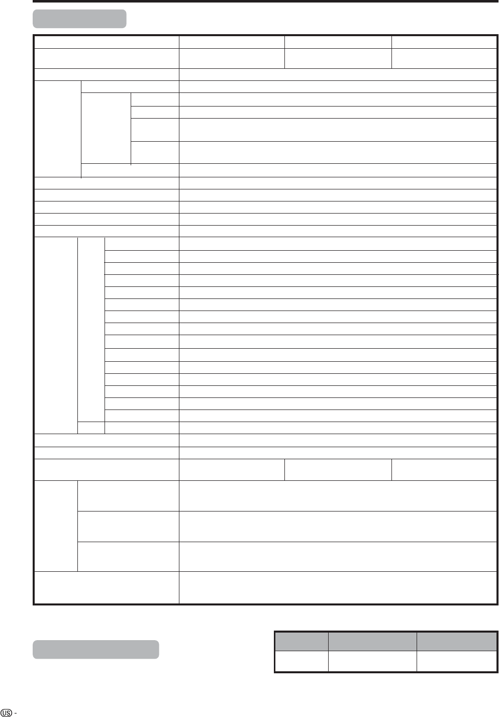
96
Appendix
Item Model: LC-37GD4U
TV
Function
American TV Standard ATSC/NTSC System
VHF/UHF VHF 2-13ch, UHF 14-69ch
CATV 1-125ch
Audio multiplex BTSC System
Terminals AV in, COMPONENT in
INPUT 2 AV in, COMPONENT in
INPUT 4 HDMI in (Type-A) with HDCP
ANALOG ANTENNA
75 q Unbalance, F Type for VHF/UHF/CATV in m 2, out m 1
INPUT 3 S-VIDEO in, AV in
OSD language English/French/Spanish
Power Requirement AC 120 V, 60 Hz
Power Consumption
Weight
Accessories Operation manual (m1), Remote control unit (m1), AC cord (m1), “AAA” size
battery (m2), Cable clamp (m1), RF cable (m1), Speaker unit (m1), Bracket
unit (m1) (only for LC-37GD4U/LC-32GD4U)
TV-standard (CCIR)
Receiving
Channel
Rear INPUT 1
Front
• As part of policy of continuous improvement, SHARP reserves the right to make design and specification changes for product improvement
without prior notice. The performance specification figures indicated are nominal values of production units. There may be some
deviations from these values in individual units.
Specifications
LCD panel 37o Advanced Super
View & BLACK TFT LCD
Number of dots 3,147,264 dots (1366 m 768 m 3 dots)
Brightness 450 cd/m2
Backlight 60,000 hours (at Backlight Standard position)
Viewing angles H : 170° V : 170°
Audio amplifier 10W m 2
Speakers Ø 8cm 2pcs, Ø 2.5cm 2pcs
MONITOR OUTPUT
S-VIDEO out, AV out
Headphones Ø 3.5mm jack
224 W (0.2 W Standby
with AC 120 V)
40.8 lbs./18.5 kg (Display only),
51.6 lbs./23.4 kg (with Display and speaker),
60.8 lbs./27.6 kg (with Display, speaker and standby)
CENTER CHANNEL INPUT
RCA pin
4q 10W (L/R)
EXTERNAL SPEAKER
Optional accessory
The listed optional accessory is available for the Liquid Crystal
Television. Please purchase it at your nearest shop.
• Additional optional accessories may be available in the near
future. When purchasing, please read the newest catalogue for
compatibility and check the availability.
INPUT 5 Audio in, DVI-I in with HDCP
No.
Wall mount bracket
Part name Part number
1 AN-37AG2
Model: LC-32GD4U Model: LC-26GD4U
Digital Terrestrial
Broadcast (8VSB)
2-69ch
Digital cable
(64/256 QAM)
1-135ch
for LC-37GD4U/LC-32GD4U
182 W (0.2 W Standby
with AC 120 V)
150 W (0.2 W Standby
with AC 120 V)
32o Advanced Super
View & BLACK TFT LCD
26o Advanced Super
View & BLACK TFT LCD
DIGITAL ANTENNA
75 q–for Digital Air/Cable in m 1
DIGITAL AUDIO OUTPUT
Optical Digital audio output m 1 (PCM/Dolby Digital)
i.LINK IEEE1394 m 2 with DTCP
PC CARD slot 68 pin PCMCIA m 1
Cable CARD slot 68 pin PCMCIA m 1
DC OUTPUT DC 9 V 7 W MAX
LC-37GD4U
36.4 lbs./16.5 kg (Display only),
46.1 lbs./20.9 kg (with Display and speaker),
55.3 lbs./25.1 kg (with Display, speaker and standby)
LC-32GD4U
XX.X lbs./XX.X kg (Display only),
XX.X lbs./XX.X kg (with Display and speaker),
XX.X lbs./XX.X kg (with Display, speaker and standby)
LC-26GD4U
97
Dimensional drawings
Unit: inch/(mm)
Display LC-37GD4U
917
1102
634
548
361
822.6
463.8
99
671
102
307
115
200
200
95.9
361
98
307
99
671
102
700.4
395.1
327
795
565
980
115
480
200
61.5
200
327
Dimensional drawings
Unit: inch/(mm)
Display LC-32GD4U
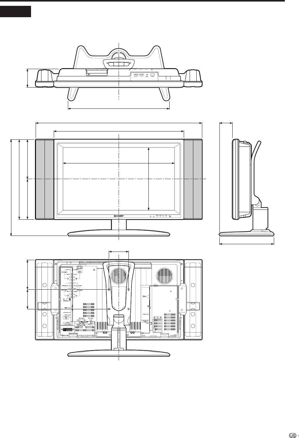
99
Dimensional drawings
Unit: inch/(mm)
Display LC-26GD4U
68
278
568
321
663
848
206
493
201 95
407
517
100
100 151
100
HOW TO SET THE FACTORY PRESETS
Turn off the Display by pressing POWER.
Press and hold down RESET and press POWER on the Display to turn on the TV.
All setting items (except TV channel) return to the factory presetting.
NOTE
• Running the factory presetting operation also clears the secret number.
You can run the EZ Setup again by using the following steps.
1Turn on the power of the Display.
2Press MENU. (Make sure the menu screen displays.)
3Press c/d to select “Setup”.
4Press a/b to select “EZ Setup”.
5Press ENTER.
NOTE
• If the secret number setting screen displays, you need to enter your secret number.
• If you forget your secret number, refer to HOW TO SET THE FACTORY PRESETS above.
NOTE
• As a precautionary measure, make a note of your secret number above, scissor it from this manual, and keep it in a
familiar place.
The secret number is .
101
CONSUMER LIMITED WARRANTY
SHARP ELECTRONICS CORPORATION warrants to the first consumer purchaser that this Sharp brand product (the
“Product”), when shipped in its original container, will be free from defective workmanship and materials, and agrees that it
will, at its option, either repair the defect or replace the defective Product or part thereof with a new or remanufactured
equivalent at no charge to the purchaser for parts or labor for the period(s) set forth below.
This warranty does not apply to any appearance items of the Product nor to the additional excluded item(s) set forth below
nor to any Product the exterior of which has been damaged or defaced, which has been subjected to improper voltage or
other misuse, abnormal service or handling, or which has been altered or modified in design or construction.
In order to enforce the rights under this limited warranty, the purchaser should follow the steps set forth below and provide
proof of purchase to the servicer.
The limited warranty described herein is in addition to whatever implied warranties may be granted to purchasers by law.
ALL IMPLIED WARRANTIES INCLUDING THE WARRANTIES OF MERCHANTABILITY AND FITNESS FOR USE ARE
LIMITED TO THE PERIOD(S) FROM THE DATE OF PURCHASE SET FORTH BELOW. Some states do not allow limitations
on how long an implied warranty lasts, so the above limitation may not apply to you.
Neither the sales personnel of the seller nor any other person is authorized to make any warranties other than those
described herein, or to extend the duration of any warranties beyond the time period described herein on behalf of Sharp.
The warranties described herein shall be the sole and exclusive warranties granted by Sharp and shall be the sole and
exclusive remedy available to the purchaser. Correction of defects, in the manner and for the period of time described
herein, shall constitute complete fulfillment of all liabilities and responsibilities of Sharp to the purchaser with respect to the
Product, and shall constitute full satisfaction of all claims, whether based on contract, negligence, strict liability or otherwise.
In no event shall Sharp be liable, or in any way responsible, for any damages or defects in the Product which were caused
by repairs or attempted repairs performed by anyone other than an authorized servicer. Nor shall Sharp be liable or in any
way responsible for any incidental or consequential economic or property damage. Some states do not allow the exclusion
of incidental or consequential damages, so the above exclusion may not apply to you.
THIS WARRANTY GIVES YOU SPECIFIC LEGAL RIGHTS. YOU MAY ALSO HAVE OTHER RIGHTS WHICH VARY FROM
STATE TO STATE.
Model Specific Section
Your Product Model Number & Description:
Warranty Period for this Product:
Additional Item(s) Excluded from
Warranty Coverage (if any):
Where to Obtain Service:
What to do to Obtain Service: LC37GD4U/LC-32GD4U
LC-26GD4U
LC-37GD4U • LC-32GD4U • LC-26GD4U LCD Color Television
(Be sure to have this information available when you need
service for your Product.)
One (1) year parts and labor from the date of purchase.
Non-rechargeable batteries.
From a Sharp Authorized Servicer located in the United States.
To find the location of the nearest Sharp Authorized Servicer,
call Sharp toll free at 1-800-BE-SHARP.
Contact your Sharp Authorized Servicer to obtain in-home
service for this Product. The Servicer will come to your home
and if it is necessary to remove the Product, the Servicer will
reinstall it. Be sure to have Proof of Purchase available.
Ship prepaid or carry in your Product to a Sharp Authorized
Servicer. Be sure to have Proof of Purchase available. If you
ship the Product, be sure it is insured and packaged securely.
Calling for Service
For location of the nearest Sharp Authorized Service, or to obtain product literature, accessories, supplies, or
customer assistance, please call 1-800-BE-SHARP.
LIMITED WARRANTY
SHARP ELECTRONICS CORPORATION
Sharp Plaza, Mahwah, New Jersey 07430-2135
SHARP CORPORATION
TO OBTAIN PRODUCT INFORMATION, CALL 1-800-BE-SHARP OR VISIT www.sharpusa.com
102
LIMITED WARRANTY
Consumer Electronics Products
Congratulations on your purchase!
Sharp Electronics of Canada Ltd. (hereinafter called “Sharp”) gives the following express warranty to the first consumer purchaser for this
Sharp brand product, when shipped in its original container and sold or distributed in Canada by Sharp or by an Authorized Sharp Dealer:
Sharp warrants that this product is free, under normal use and maintenance, from any defects in material and workmanship. If any such
defects should be found in this product within the applicable warranty period, Sharp shall, at its option, repair or replace the product as
specified herein.
This warranty shall not apply to:
(a) Any defects caused or repairs required as a result of abusive operation, negligence, accident, improper installation or inappropriate
use as outlined in the owner’s manual.
(b) Any Sharp product tampered with, modified, adjusted or repaired by any party other than Sharp, Sharp’s Authorized Service Centres
or Sharp’s Authorized Servicing Dealers.
(c) Damage caused or repairs required as a result of the use with items not specified or approved by Sharp, including but not limited to
head cleaning tapes and chemical cleaning agents.
(d) Any replacement of accessories, glassware, consumable or peripheral items required through normal use of the product including but
not limited to earphones, remote controls, AC adapters, batteries, temperature probe, stylus, trays, filters, belts, ribbons, cables and
paper.
(e) Any cosmetic damage to the surface or exterior that has been defaced or caused by normal wear and tear.
(f) Any damage caused by external or environmental conditions, including but not limited to transmission line/power line voltage or liquid
spillage.
(g) Any product received without appropriate model, serial number and CSA/cUL markings.
(h) Any products used for rental or commercial purposes.
(i) Any installation, setup and/or programming charges.
Should this Sharp product fail to operate during the warranty period, warranty service may be obtained upon delivery of the Sharp product
together with proof of purchase and a copy of this LIMITED WARRANTY statement to an Authorized Sharp Service Centre or an
Authorized Sharp Servicing Dealer. In home warranty service may be provided at Sharp’s discretion on any Sharp television with the
screen size of 27” or larger and on any Sharp Over-the-Range Microwave Oven.
This warranty constitutes the entire express warranty granted by Sharp and no other dealer, service centre or their agent or employee is
authorized to extend, enlarge or transfer this warranty on behalf of Sharp. To the extent the law permits, Sharp disclaims any and all
liability for direct or indirect damages or losses or for any incidental, special or consequential damages or loss of profits resulting from a
defect in material or workmanship relating to the product, including damages for the loss of time or use of this Sharp product or the loss
of information. The purchaser will be responsible for any removal, reinstallation, transportation and insurance costs incurred. Correction of
defects, in the manner and period of time described herein, constitute complete fulfillment of all obligations and responsibilities of Sharp
to the purchaser with respect to the product and shall constitute full satisfaction of all claims, whether based on contract, negligence, strict
liability or otherwise.
WARRANTY PERIODS:
Parts & Labour (exceptions noted)
Audio Products 1 year
Camcorder 1 year
DVD Products 1 year
Projector 1 year (lamp 90 days)
LCD & Plasma Display TV 1 year
Microwave Oven 1 year (magnetron component-4 additional years)
Television Products 1 year (picture tube component-1 additional year)
VCR Products 1 year
Vacuum Cleaner 1 year
To obtain the name and address of the nearest Authorized Sharp Service Centre or Dealer, please contact:
SHARP ELECTRONICS OF CANADA LTD. 335 Britannia Road East, Mississauga, Ontario L4Z 1W9
For more information on this Warranty, Sharp Extended Warranty
Offers, Sharp Canada Products, Accessory Sales, Dealer or Service
Locations, please call (905) 568-7140
Visit our Web site: www.sharp.ca
VALID IN CANADA ONLY
Revision 04/22/03
