ShenZhen ART TECH R C Hobby ETB62A 2.4GHz Radio Control system User Manual
ShenZhen ART-TECH R/C Hobby Co., Ltd 2.4GHz Radio Control system
User Manual
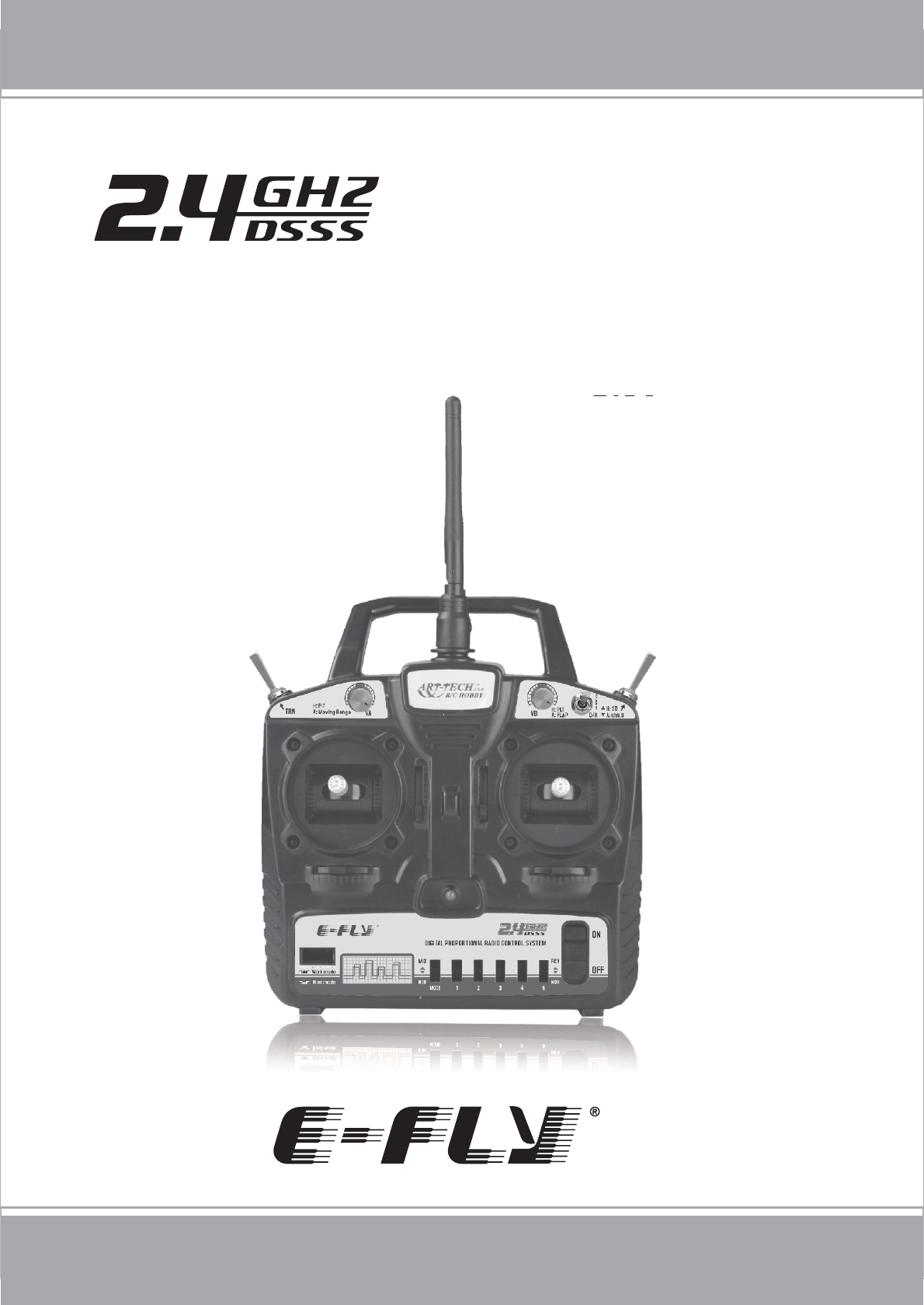
ETB62A-2.4GHz
6 CHANNEL DIGITAL PROPORTIONAL RADIO
CONTROL SYSTEM MANUAL

www.art-tech.com
TABLE OF CONTENTS
2
Package List ...........................................................................3
Precautions for Keeping ...........................................................3
Meaning of Special Markings ....................................................4
Precautions During Flight Warning ............................................4
Transmitter .............................................................................5
Transmitter particular introduce ................................................6
functions of the RC device .........................................................7
Other function of transmitter ......................................................7
Receiver ................................................................................9
Manual for Brushed ESC ........................................................10
Transmitter Operation and Movement of each Servo (Mode 1)...11
The process of frequency bind for 2.4GHz R/C system ............12
The using of trainer function ..................................................13
Adjustments .........................................................................14
The using of computer-controlled interface .............................14
Glossary ..............................................................................15
Thank you for purchasing the E-Fly ETB62A-2.4GHz Digital Proportional Radio
Control System. Before you operate this unit, please read and keep this manual
carefully. Please comply the proper procedures strictly, user must be responsible
for the damages of radio system and model or other loss caused by incorrect
operation.
3
www.art-tech.com
PACKAGE LIST
High quality joystick Low voltage alarm
Servo reverse function
Trainer port available
Remote control
ETB62A-2.4GHz is a 6 channel full-scale 2.4GHZ RC device. It adopts the technology of
direct sequence spread spectrum (DSSS), FDMA, CDMA and frequency hopping to have
good anti-interference, stability and reliability.
It can be used for all ordinary aeroplanes, delta wing aeroplanes, gliders, coaxial
helicopters, general helicopter and CCPM helicopter models, and so on. It has 6 channel
output and simulator signal interface. It also has such functions as Dual Rate(D/R), Mode
I and Mode II exchange and low voltage alarm.
The most characteristic feature of ETB62A-2.4GHz RC device is the cordless trainer
function. It means flight instruction can be realized without the trouble of cord
connection and this makes learning easier for green hand.
PRECAUTIONS FOR KEEPING
If it is your first using, please make sure the receiver can be controlled by the
transmitter. If not, please rebind. Details can be found in Bind Process
Description.the transmitter and the receiver must be bind again. More details ,
ease refer to the process of frequency bind for 2.4 GHz R/C System.
Please do not turn on several RC devices and bind them at the same time, only
turn on a set of RC device at one time.
Do not store the radio system in the damp, dusty and vibratory place, temperature
oo
over 40 C or under -10 C and direct sunlight for long time.
Transmitter: ETB62A-2.4GHz 1pcs
Receiver: ER62-2.4GHz 1pcs
Simulator cable: 1pcs
Neck strap(optional): 1pcs
Manual: 1pcs
CD: 1pcs
We do not offer servo, speed controller, battery
or changer with the radio control system .
Users can buy as spare parts.
Servo: AS-100(9 g) 3 pcs
Speed controller: ESC-30A 1 pcs
Battery packs: 9.6V/Ni-MH 1 pcs
Charger: 1 pcs
Cordless trainer function
For AERO/HELI/GLIDERS
Fully proportional
Great Features:
4
Pay special attention to the safety at the parts of this manual that are indicated
by the following marks.
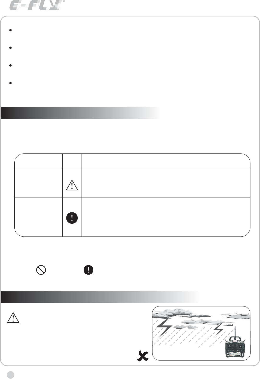
Do not fly in rainy or windy days, or at
night. Water will penetrate into the
transmitter and cause faulty operation,
or loss of control, and cause a crash.
MEANING OF SPECIAL MARKINGS
PRECAUTIONS DURING FLIGHT WARNING
www.art-tech.com
CAUTION Procedures where the possibility of serious injury to the user is small,
but there is a danger of injury, or physical damage, if not carried out properly.
Symbol: Prohibited Mandatory
MARK
DANGER
WARNING
MEANING
Procedures which may lead to a dangerous condition
and cause death or serious injury to theuser if not
carried out properly.
Procedures which may lead to dangerous condition or
cause death or serious injury to the user if not carried
out properly, or procedures where the probability of
superficial injury or physical damage is high.
WARNING!
If there is a long time not for use, please take the battery out from the transmitter
and keep it in the dry place.
Forbid to wipe the radio system with the organic liquor such as thinner, acetone
and chloroform.
Do not throw away the using up batteries, please keep them in the metalloid
container and transfer them to the environmental conservation institution.
On purpose of environmental conservation and low using cost , we suggest you
use the rechargeable Ni-MH battery.
5
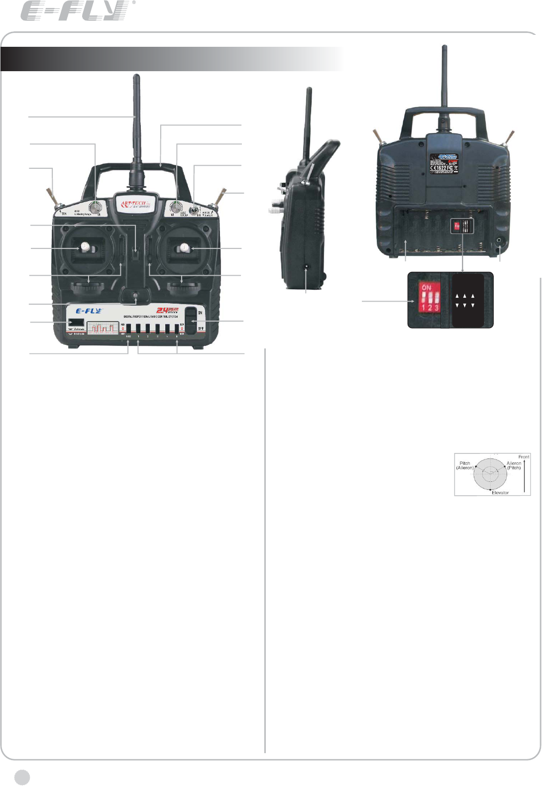
TRANSMITTER
www.art-tech.com
Always test the digital proportional R/C set
before use. Any abnormality in the digital
proportional R/C set, or model, may cause a
crash. Before starting the engine, check that
the direction of operation of each servo
matches the operation of its control stick. If a
servo does not move in the proper direction,
or operation is abnormal, do not fly the
plane.
We offer Mode I and Mode II two types of transmitter for selection. Customers
should choose one according to their individual needs.
You will need 8 AA batteries for operating the transmitter.
Please do not press the frequency bind switch when the Transmitter at work
mode, or else your device will not work!
If the indicator of the transmitter or the receiver flashing once every two
seconds after turn on the power please bind the frequency of the transmitter
and the receiver again.
Low battery voltage alarm function.
The transmitter will emit a high-pitched tone if the battery voltage gets too low.
The transmitter can not work properly if the
frequency bind button is pressed down
neglectfully. In this case, The transmitter
and the receiver must be bind again.
More details , ease refer to the process
of frequency bind for 2.4 GHz R/C system.
Please do not turn on several RC devices and
bind them at the same time, bind only one set
of RC device at one time. The RC device should
not be stay in bind state for a long time.
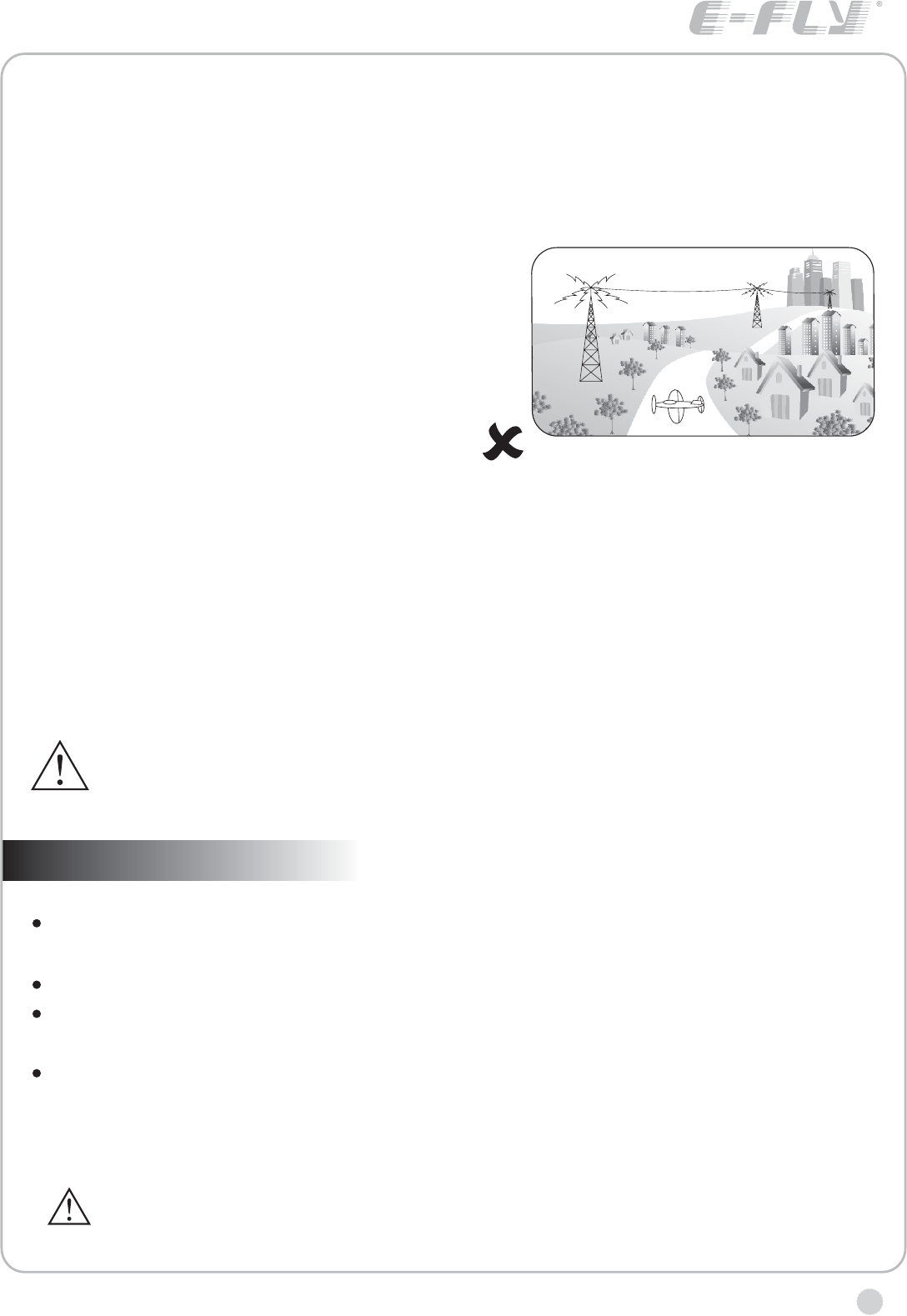
Do not fly the plane near the house,
road,electrical wire and airport.
www.art-tech.com
6
Transmitter particular introduce
R
A
I
O
Q
B
J
N
CD
EF
P
L
G
H
K
M
A:Antenna
B:Handle
C:VA
1) For aeroplanes, it is for small rate adjustment of
channel 1,2 and 4;
2) For helicopters, it is the fine-tuning for the PIT.
D:VB
1) For aeroplanes, it is for adjustment of channel 6,
usually used for output setting of flap;
2) For helicopters, it is the fine-tuning for the PLT.
E:Trainer switch
F:Dual Rate(D/R) Switch
1) For aeroplanes, When it is 1,it is adjusted by knob A,
from 20% to 100%; When it is 0, it means the turning range
of servos is 100%.
2) For helicopters, The switch is to change the turning
range of servos(100% / 70% )for CH1, CH2 and CH4.
When it is 0, it means the turning range of servos is 100%.
When it is 1, it means the turning range of servos is 70%.
G:Flying Ring
H:Switch
1) For aeroplanes, this switch is for Ch5 and Ch6 and
can be used for collapsible landing gear, aerial camera
and flap control, etc.
2) For helicopters, it is the 3D switch.
I:Joystick
1) If the transmitter is Model 1,CH2 is for elevator and
CH4 for rudder.
2) If the transmitter is Model 2,CH3 is for throttle and CH4
for rudder.
J:Joystick
1) If the transmitter is Model 1,CH1 is for aileron and
CH3 for throttle.
2) If the transmitter is Model 2,CH1 is for aileron and
CH2 for Rudder
K:Trim levers
L:Trim levers
M:LED Indicator for Power
N:Switch for Power
O:Bind Button
P:mixed control switch
1) For aeroplanes, NOR means no mixing, MIX means
mixing control for the CH1 and CH2;
2) For helicopters, NOR means
independent aileron, pitch and elevator
servos linked to the swashplate. MIX
means CCPM helicopter. With Aileron
inputs, the aileron and pitch servos tilt the swashplate left
and right; with Elevator inputs, the three servos tilt the
swashplate fore and aft; with Pitch inputs, all three servos
raise the swashplate up and down.
Q:CH1, CH2, CH3, CH4, CH6 reverse switch
1) aileron reverse switch
2) elevator reverse switch
3) throttle reverse switch
4) rudder reverse switch
6) flap / pitch reverse switch
R:Rechargeable plug
S:Battery bay for transmitter
T:Plug for Simulator
U:mode selection switch
1: ACRO for aeroplanes, HELI for the helicopters.
2: MODE 1 and MODE 2 selection.
3: frequency range selection switch, the usable frequency
range of 2.4GHz is different in some countries, for
example, in France only 2.400 ~ 2.454GHz can be used.
2.400 ~ 2.483GHz can be used in the majority of countries,
FREQ1 for 2.400 ~ 2.483GHz, FREQ2 for 2.400 ~ 2.454GHz
MODE II
ACRO
MODE I
1
2
3
FREQ I FREQ II
HELI
ST
U

7
www.art-tech.com
functions of the RC device
ETB62A-2.4GHz has a variety of flight mode.It can be used for all ordinary aeroplanes,delta
wing aeroplanes,gliders, coaxial helicopters, general helicopter and CCPM helicopter models,
and so on.
A: ordinary aeroplanes
Settings: Set switch U(1) to ACRO,Set switch P to NOR
Use: 1.by adjusting fine-tuning knob A,the turning range of servos for CH1,CH2 and CH4 can be
adjust form 20 % to 10 0%
2.Small Rate can be choosen by setting the switch F to 1.
3.switch A is for CH6 flap and CH5 collapsible landing gear at the same time. Flap can be
adjusted by fine-tuning knob B form 0% to 100%
4.by setting the switch set Q,the reverse setting of CH1,CH2,CH3,CH4 and CH6 can be adjusted.
B: delta wing aeroplanes
Settings: Set switch U(1) to ACRO,Set switch P to MIX
Use: 1.by adjusting fine-tuning knob A,the turning range of servos for CH1,CH2 and CH4 can be
adjust form 20 % to 100%
2.Small Rate can be choosen by setting the switch F to 1.
3.switch A is for CH6 flap and Ch5 collapsible landing gear at the same time. Flap can be
adjusted by fine-tuning knob B form 0% to 1 00%
4.by setting the switch set Q, the reverse setting of CH1, CH2, CH3, CH4 and CH6 can be
adjusted.
C: general helicopter and coaxial helicopters
Settings: Set switch U(1) to HELI, Set switch P to NOR. For coaxial helicopter mode, set Dual
Rate(D/R) to 1.
Use: 1.CH3 and CH6 mixing for pitch control, PIT and PLT can be tuned by knob A and B
2.The switch F is to choose Dual Rate(100% / 70% )for CH1, CH2 and Ch4.
3.The switch A is for 3D mode, it is used for the stunt mode
4. by setting the switch set Q, the reverse setting of CH1, CH2, CH3, CH4 and CH6 can be
adjusted.
Note: When use coaxial helicopter mode, do not use 3D mode.
D: CCPM helicopters
Settings: Set switch U(1) to HELI, Set switch P to MIX.
Use: 1.CH1, CH2, CH3 and CH6 are mixed to achieve control for CCPM helicopter, PIT and
PLT can be tuned by knob A and B
2.The switch F is to choose Dual Rate(100% / 70% )for CH1, CH2 and CH4.
3.The switch A is for 3D mode, it is used for the stunt mode
4.by setting the switch set Q, the reverse setting of CH1, CH2, CH3, CH4 and CH6 can be
adjusted.
EBT62A-2.4GHz has the unique cordless trainer function. For details, please refer to (The
using of trainer function).
Other function of transmitter
Servo reversing switches
If the direction of servo operation is not the same as the model, adjust the reversing switches to
reverse the direction.
The lower position is the normal setting and the upper position is the reverse setting.
C
A
B
D
www.art-tech.com
8
Working modes' option
MIX: delta-wing or V type tail-wing mode
NOR: normal mode
Operating direction display
REV.: Reverse setting
NOR.: Normal setting
Stick lever spring tension adjustmentThe stick spring tension can be adjusted. The
operating feel of the aileron, elevator, and rudder sticks can be individually adjusted.
Remove the four transmitter rear case
screws and remove the rea case.
Adjust the spring strength by turning
the screw of the channel you want
to adjust.
Close the rear case and tighten The
four screws.Stick length adjustment.
Turn the head of stick.
TRAINER JACK
Connects the trainer cord when using the trainer function (The trainer cord is sold
separately), see part 8 for the details of the trainer function.
BATTERY COVER
Use when replacing the battery. Slide the cover downward while pressing the
part marked PUSH
MODE I AND MODE II SETTING
Before setting mode I and mode II ,please turn off the power of the plane.
Press the sub button, enter into the Mode I and Mode II setting
menu.Before Mode Setting, please unplug the power supply of
the plane.Adjustment of joysticks
The screws for mode setting are in the rear cover. as shown in
the figure:
and the screws C
Therefore, for mode I, loosen
screws B and D. For mode II, loosen thescrews B and D, tighten
And then set the second switch of the switch set U to set the right mode.
The screws A and B play the role of suppressing springs;
and D play the role of adjusting resist force.
the screws A and C, tighten the
1.
2.
Channel display
AIL.: Aileron (CH1)
ELE.: Elevator (CH2)
THR.: Throttle (CH3)
RUD.: Rudder (CH4)
Aeroplanes: flap control
Helicopters: pitch control (CH6)
9
www.art-tech.com
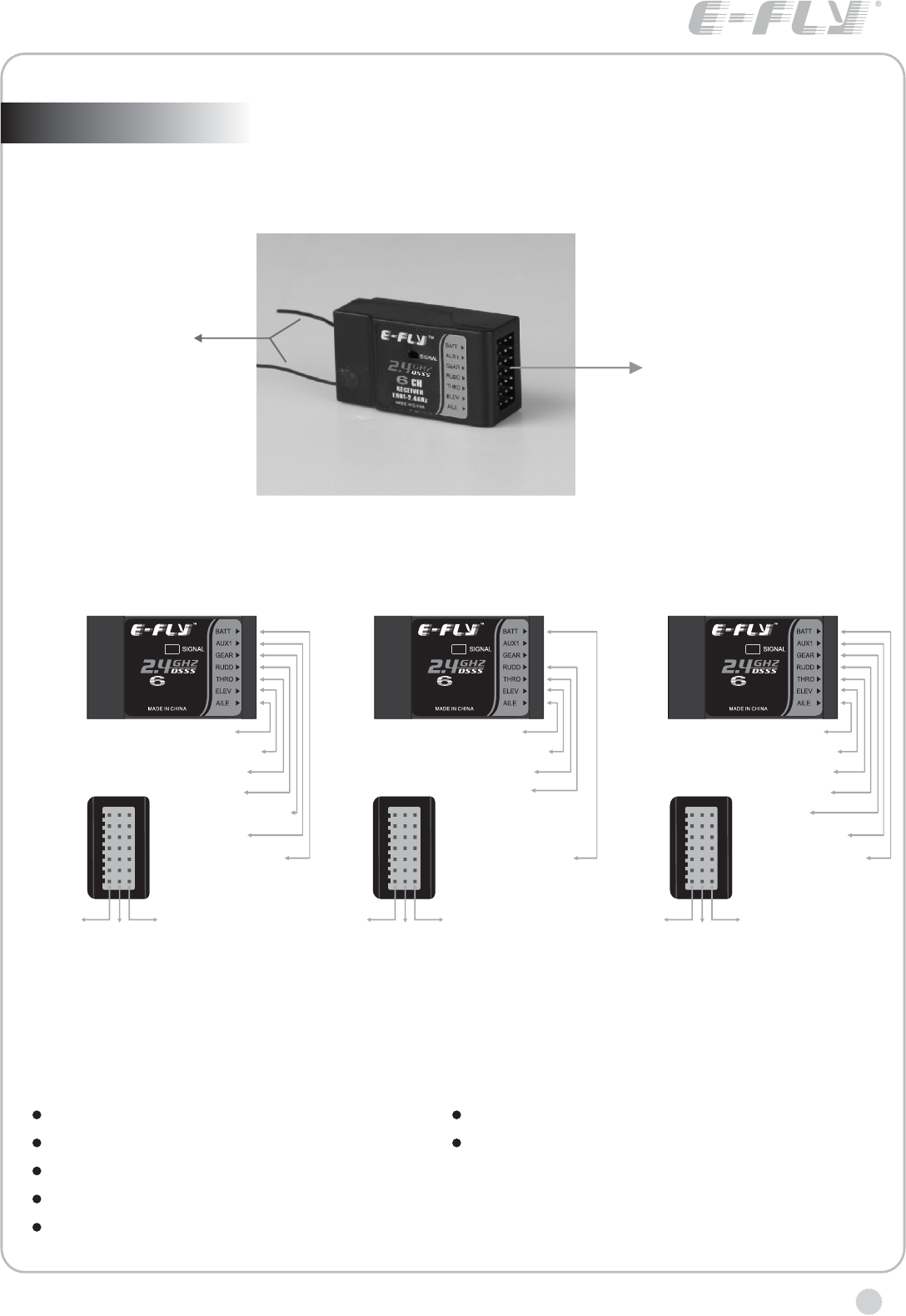
RECEIVER
With E-FLY ER62-2.4GHz receiver, the max range is 1000 feet (350m) in
the air, suitable for small park flyer type model plane.
Antenna
Output channels
SPECIFICATIONS AND PARAMETERS
Operating voltage:
Current drain:
Weight: 12g
Dimension:
4.8V~6V
≤40mA
44mm*23mm*15mm
Channel: 6CH
Range(Height): m
coaxal dual HELI)
≥350
≥50m (with
Adjacent channel rejection: ≥-85dBm
OPERATION FOR
AIRPLANES
OPERATION FOR
COAXAL DUAL ROTOR
OPERATION FOR
AIRPLANES
RECEIVER
ER62-2.4GHz
CH
6.Flapron
5.Landing gear
4.Rudder
3.Throttle
2. Elevator
1.Aileron
B. Power/Bind
+
(Red line)
-
(Black line)
Signal
(White line)
RECEIVER
ER62-2.4GHz
CH
4.Rudder
3.Throttle
2. Elevator
1.Aileron
B. Power/Bind
+
(Red line)
-
(Black line)
Signal
(White line)
RECEIVER
ER62-2.4GHz
CH
6. Gyro gain
5. Pitch
4. Rudder
3. Throttle
2. Elevator
1. Aileron
B. Power/Bind
+
(Red line)
-
(Black line)
Signal
(White line)
www.art-tech.com
10
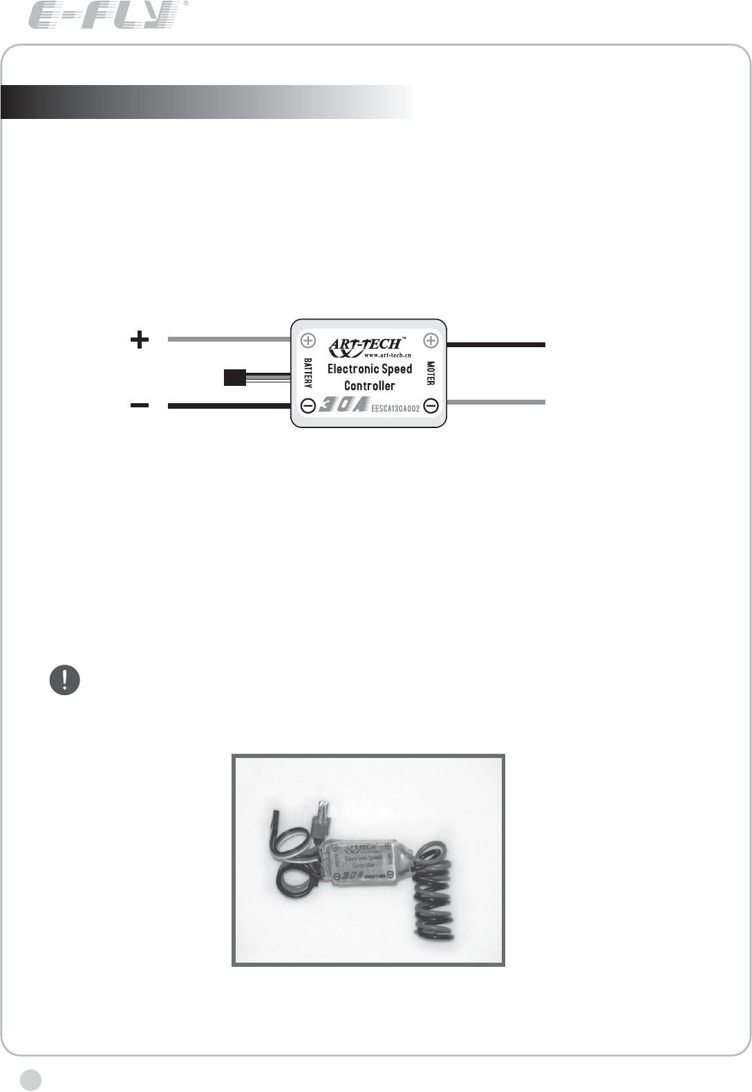
MANUAL FOR BRUSHED ESC
Specifications for ESC-30A
Working currency:30A/50A(max currency)
input voltage:DC,5V-14.4V.
starting mode:adaptable point(1.0ms-1.5ms)
control mode:200 class proportional
output voltage(BEC) :5V/1A(direct for servo )
Auto cut-off function
When the voltage of battery in model plane is under working voltage,
function of cutting the power to the motor and only supply to receiver in order to save
power. In that case, the model plane should be landed immediately for the sake of
safety.
ESC has the
Notice
It is better to choose proper motor and battery in oder not to over load.
And please pay attention to the conntion between ESC and the motor.
In working condition, the ESC will become hot,so please pay attention
to that.
To motor
To receiver
To battery
To battery
www.art-tech.com 11
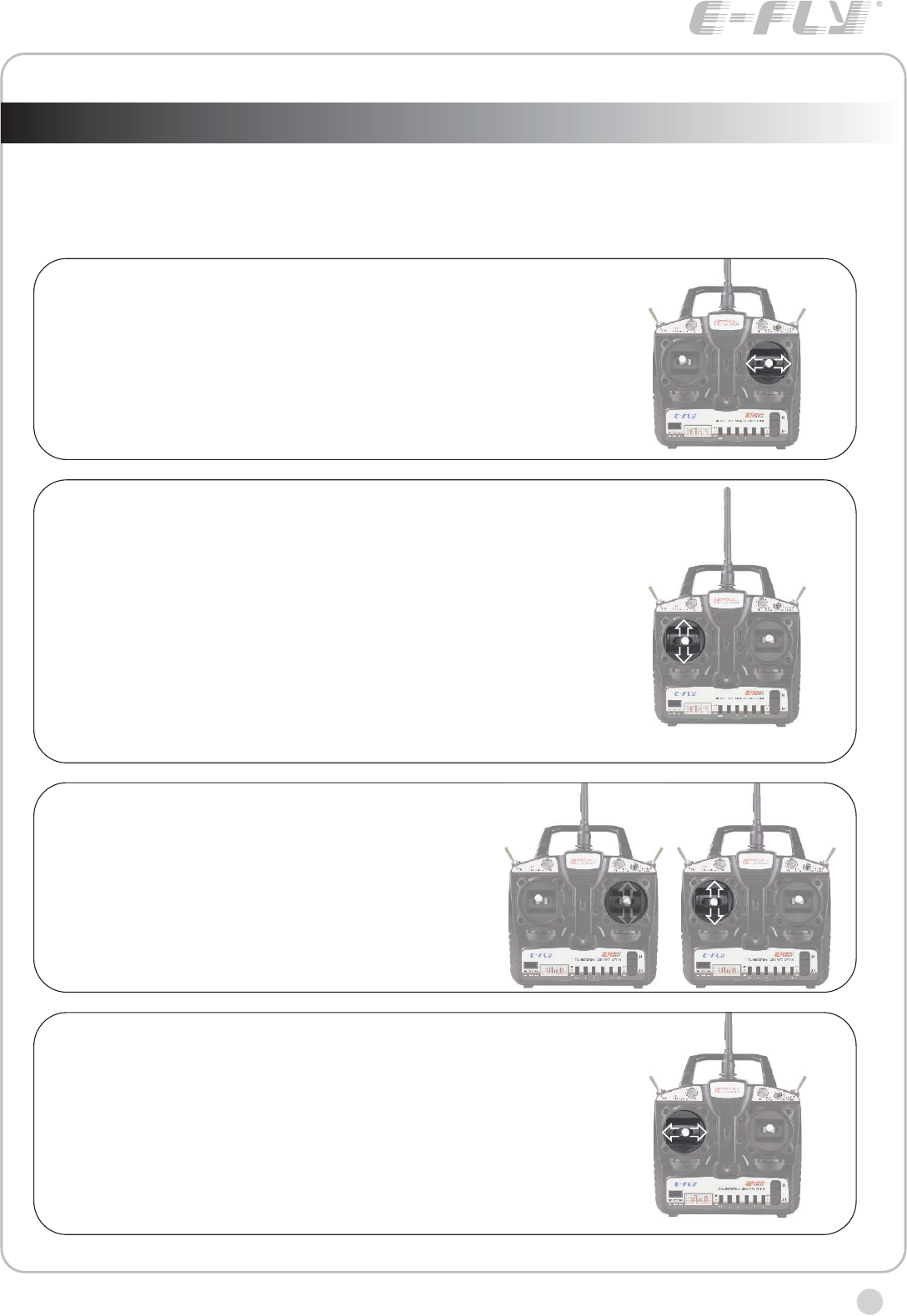
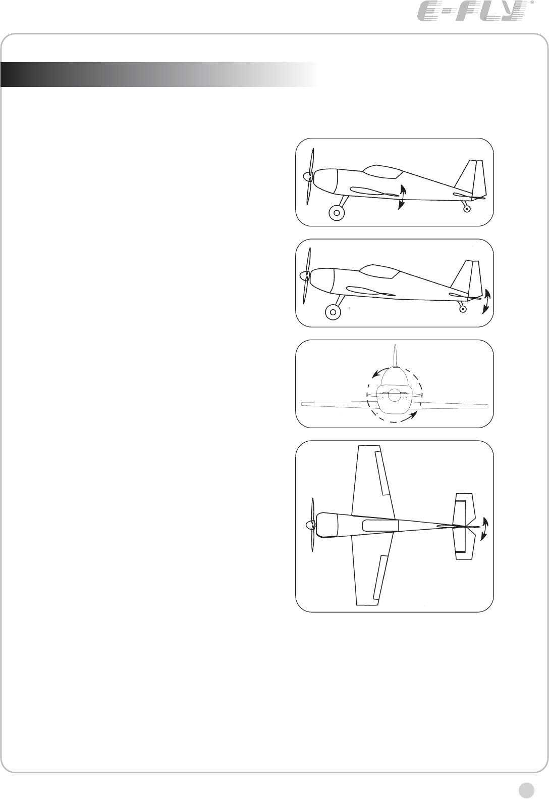
RUDDER OPERATION
When the rudder stick is moved to the right, the
rudder moves to the right and the nose points to the
right, relative to the direction of flight. When the
rudder stick is moved to the left, the rudder moves to
the left and the nose points to the left and the
direction of travel of the plane changes.
THROTTLE OPERATION
When the throttle stick is pulled back, the
engine throttle lever arm moves to the SLOW
(low speed) position. When the throttle stick
is pushed forward, the throttle lever arm
moves to the HIGH (high speed) position.
TRANSMITTER OPERATION AND MOVEMENT OF EACH SERVO (Mode 1)
Before making any adjustments, learn the operation of the transmitter and the
movement of each servo. (In the following descriptions, the transmitter is
assumed to be in the standby state.)
AILERON OPERATION
When the aileron stick is moved to the right, the right
aileron is raised and the left aileron is lowered,
relative to the direction of flight, and the plane turns
to the right. When the aileron stick is moved to the
left, the ailerons move in the opposite direction.
ELEVATOR OPERATION
When the elevator stick is pulled back, the tail elevator
is raised and the tail of the plane is forced down, the
airflow applied to the wings is changed, the lifting force
is increased, and the plane climbs (UP operation).
When the elevator stick is pushed forward, the
elevator is lowered, the tail of the plane is forced up,
the air flow applied to the wings is changed, the lifting
force is decreased, and the plane dives (DOWN
operation).
mode I mode II
www.art-tech.com
12
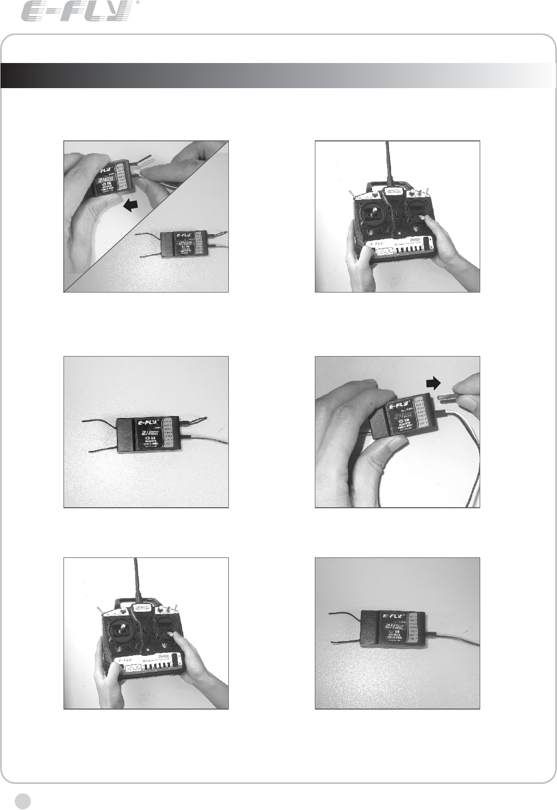
The process of frequency bind for 2.4GHz R/C system
Place the transmitter and the receiver close to each other within one (1) meter.
If oil aircraft, please connect the power of receiver to other channel at first, and then
plug it to BATT after frequency bind.
1. plug the short- circuit plug into the Receiver
in the position of BATT. Connect the ESC to
receiver for electricity supply, which results to
the indicator light glitters.
2. Press the frequency bind button, then
turn on the transmitter' s power.
6. The indicator light turns bright again,
which means that the radio system can
work normally now.
3. the indicator light of the receiver will light,
which indicates that the frequency bind is
successful.
4. Unplug the short-circuit, the indicator
light glitters.
5. Press frequency bind button again to get it
rebound. After the indicator light flashes for a
few seconds, it turns green, the transmitter
get into working mode.
www.art-tech.com 13
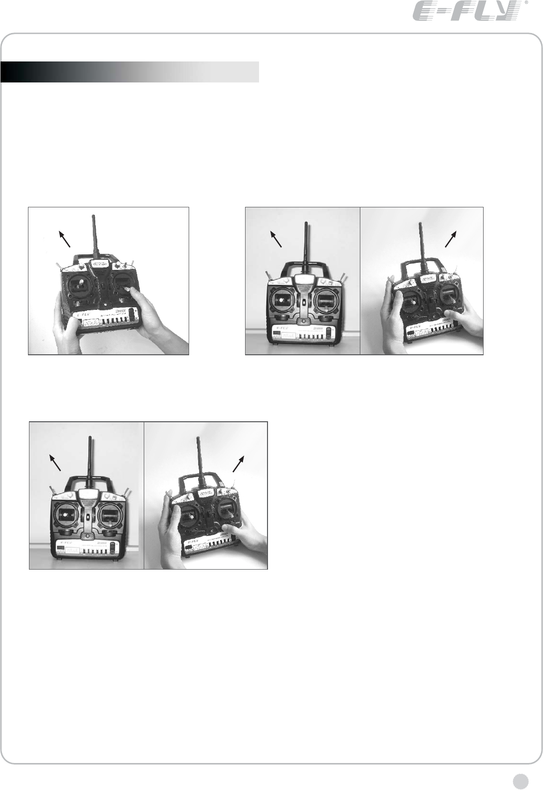
1 1
Before using trainer function, you should first bind the frequency of the master(teacher)
transmitter to the receiver, adjust the same aircraft to respectively.Before entering
into the next step, please make sure the reverse switches and mode settings are set
correctly.
Make sure that the master transmitter and the receiver have been bound (frequency bind)
The using of trainer function
the binding process of the master transmitter and the slave transmitter
3. Wait Until the indicator of the
master transmitter turns red and
the slave transmitter turns green,
which means the binding of the two
transmitter has been completed,
you can use the trainer function
now.
1. Press the frequency bind button
of the master transmitter, turn on
the power, the indicator flashes.
2. Press the frequency bind button of the slave
transmitter, put the slave near the master. turn
on the power of the salve, the indicator flashes.
Note: using the trainer function, the mater transmitter and the slave transmitter should be in
the same mode. VA,VB is controlled by the master transmitter. Before flying, the reverse
switches of the two transmitter must be correct,and then fine-tuning knob should be adjusted
to achieve the effect that when switching control, there are no changing in servo positions.
When holding the TRN switch of the master transmitter, the indicator of the salve transmitter
flashes , the slave transmitter can now control the plane; If holding the TRN switch of the
slave transmitter, the indicator of the master transmitter flashes , this is only used for the slave
to send prompt signal to the master.
using of trainer function
2
12
Red light on Green light on

www.art-tech.com
14
The operating direction, neutral position, and steering angle of each servo are
adjusted.
ADJUSTMENTS
5. Fly the plane and trim each servo.
4. After all the linkages have been connected, recheck the operating direction,
throw, etc.*Before flight, adjust the aircraft in accordance with the kit and engine
instruction manuals.
3. Check the engine throttle (speed adjustment) linkage. Change the servo horn
installation position and hole position so that the throttle is opened fully when
the throttle stick is set to HIGH (forward) and is closed fully when the throttle
stick and throttle trim are set for maximum slow (backward position and lower
position, respectively).
2. Check the aileron, elevator, and rudder neutral adjustment and left-right (up-
down) throw. Check that when trimmed to the center, the servo horn is
perpendicular to the servo and check the neutral position of the fuselage control
surfaces (aileron, elevator, rudder, etc.). If the neutral position has changed,
reset it by adjusting the length of the rod with the linkage rod adjuster.
When the throw is unsuitable (different from steering angle specified by the kit
instruction manual), adjust it by changing the servo horn and each control
surface horn rod.
ADJUSTMENT PROCEDURE
Before making any adjustments, set all the SERVO REVERSER switches on the
front of the transmitter to the lower (NOR) position. (Switch the switches with a
small screwdriver, etc.) Turn on the transmitter and receiver power switches and
make the following adjustments:
1. Check the direction of operation of each servo If a servo operates in the wrong
direction, switch its SERVO REVERSER switch. (The direction of operation can
be changed without changing the linkage.) * Note that the direction of the aileron
servo is easily mistaken.
The jack on the left side of the transmitter can be connected to the computer via a
simulation cable , the beginner can practise flying on the computer. This learning
process can make the green hand be familiar with the operation and reduce the
damage, please refer to the specific CD-ROM for more information.
The using of computer-controlled interface
www.art-tech.com 15
GLOSSARY
The following defines the symbols and terms used in this instruction manual.
AILERON (AIL.)
Control surface at the left and right
sides of the main wing of an
aircraft. It usually controls turning
of the aircraft.
ELEVATOR(ELE.)
Control surface that moves up and
down of the horizontal stabilizer of
an aircraft. It usually controls up
and down.
THROTTLE (THR.)
Part that controls the air mixture at
the engine intake. When opened
(throttle high side), a large air
mixture is sucked in and the engine
speed increases. W hen closed
(throttle low side), the engine
speed decreases.
RUDDER (RUD.)
Tail control surface that controls
the direction of the aircraft.
Manufacturer reserves the right to
make improvements without
notice. Forbid to transfer and copy
contents in this manual without
consent.
There will be no notice given of any changes or improvements made .
It is forbidden to copy any of the content of this manual without permission.
2008.10
FCC Statement
This equipment has been tested and found to comply with the limits for a Class B digital device,
pursuant to part 15 of the FCC rules. These limits are designed to provide reasonable protection
against harmful interference in a residential installation. This equipment generates, uses and can
radiate radio frequency energy and, if not installed and used in accordance with the instructions,
may cause harmful interference to radio communications. However, there is no guarantee that
interference will not occur in a particular installation. If this equipment does cause harmful
interference
to radio or television reception, which can be determined by turning the equipment off and on, the
user is encouraged to try to correct the interference by one or more of the following measures:
-Reorient or relocate the receiving antenna.
-Increase the separation between the equipment and receiver.
-Connect the equipment into an outlet on a circuit different from that to which the receiver is
connected.
-Consult the dealer or an experienced radio/TV technician for help.
To assure continued compliance, any changes or modifications not expressly approved by the party
responsible for compliance could void the user’s authority to operate this equipment. (Example- use
only shielded interface cables when connecting to computer or peripheral devices).
FCC Radiation Exposure Statement
This equipment complies with FCC radiation exposure limits set forth for an uncontrolled
environment and it also complies with Part 15 of FCC RF Rules. Operation is subject to the
following two conditions:
1) This device may not cause interference and
2) This device must accept any interference, including interference that may cause undesired
operation of the device.
Caution!
The manufacturer is not responsible for any radio or TV interference caused by unauthorized
modifications to this equipment. Such modifications could void the user authority to operate the
equipment.
Declaration of Conformity
Hereby, ShenZhen ART-TECH R/C Hobby Co., Ltd., declares that this device is in compliance
with the essential requirements and other relevant provisions of Directive 1999/5/EC.

SHENZHEN ART-TECH R/C HOBBY CO.,LTD