ShenZhen ART TECH R C Hobby ETC62D 2.4GHz Radio Control system User Manual
ShenZhen ART-TECH R/C Hobby Co., Ltd 2.4GHz Radio Control system
User Manual
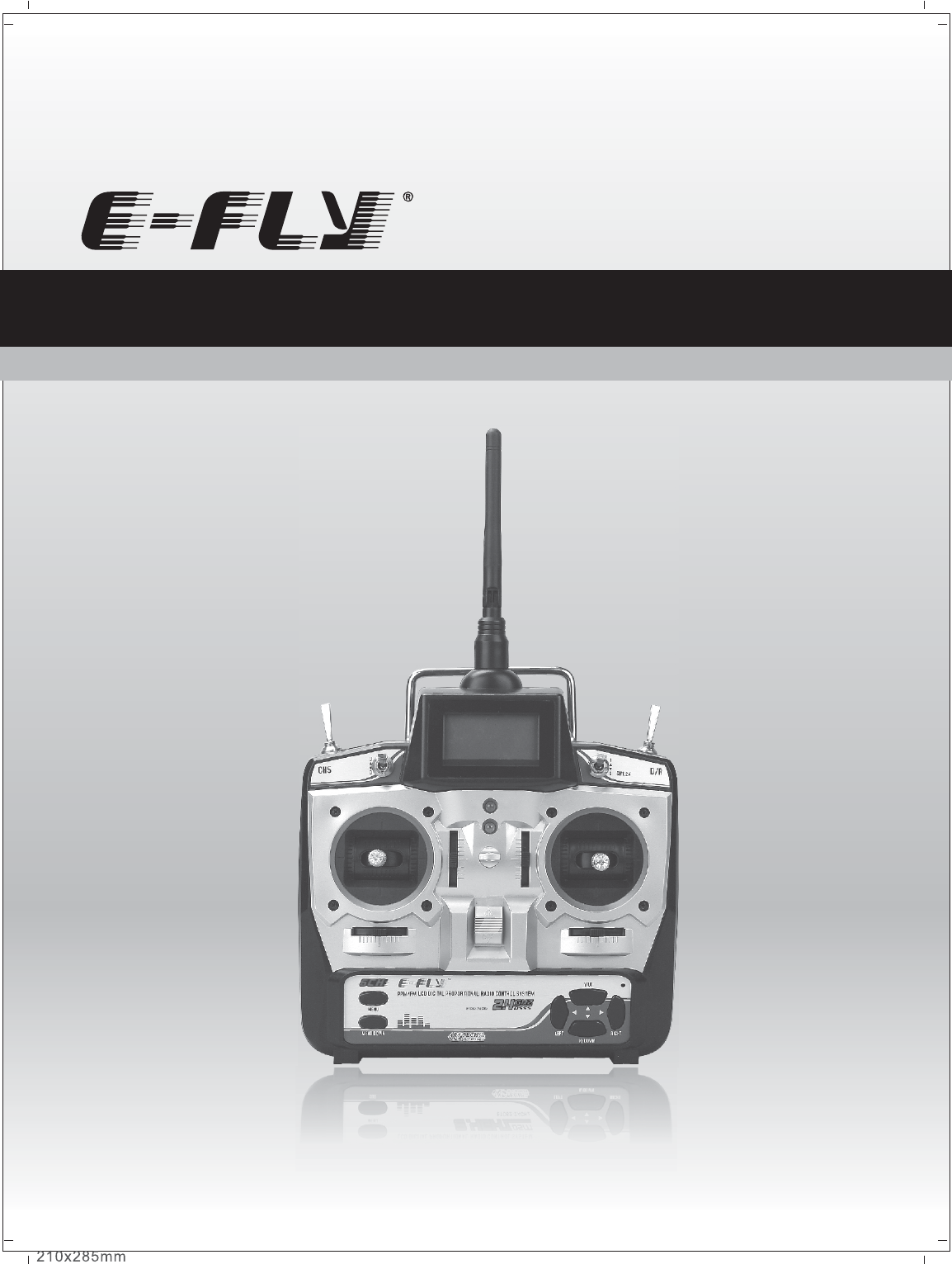
Operating Manual
LCD DIGITAL PROPORTIONAL RADIO CONTROL SYSTEM
ETC62D-2.4GHz

Catalog
Notification before Using 05
Notice for use 04
Contents 04
Specifications 04
Transmitter particular introductine 06
Menu introduction 07
Other function of the transmitter 11
Receiver 12
Electronic speed controler 10
Operation for transmitter and servo 13
Flow list 17
Function of Transmitter 0 3
Charge method of battery 16
www.art-tech.com
02
The process of frequency bind for 2.4GHz R/C system 15
Adjust order 14
Function of Transmitter
ETC62D-2.4GHz is a newly developed 6 channel proportional transmitter. The latest developed
product of ART-TECH RC Hobby Corporation. The 2.4GHz RC system uses digital frequency-hopping
technology; it has enormous advantage compared with traditional system: no crystal, no frequency
interference, short antenna length and low power consumption.
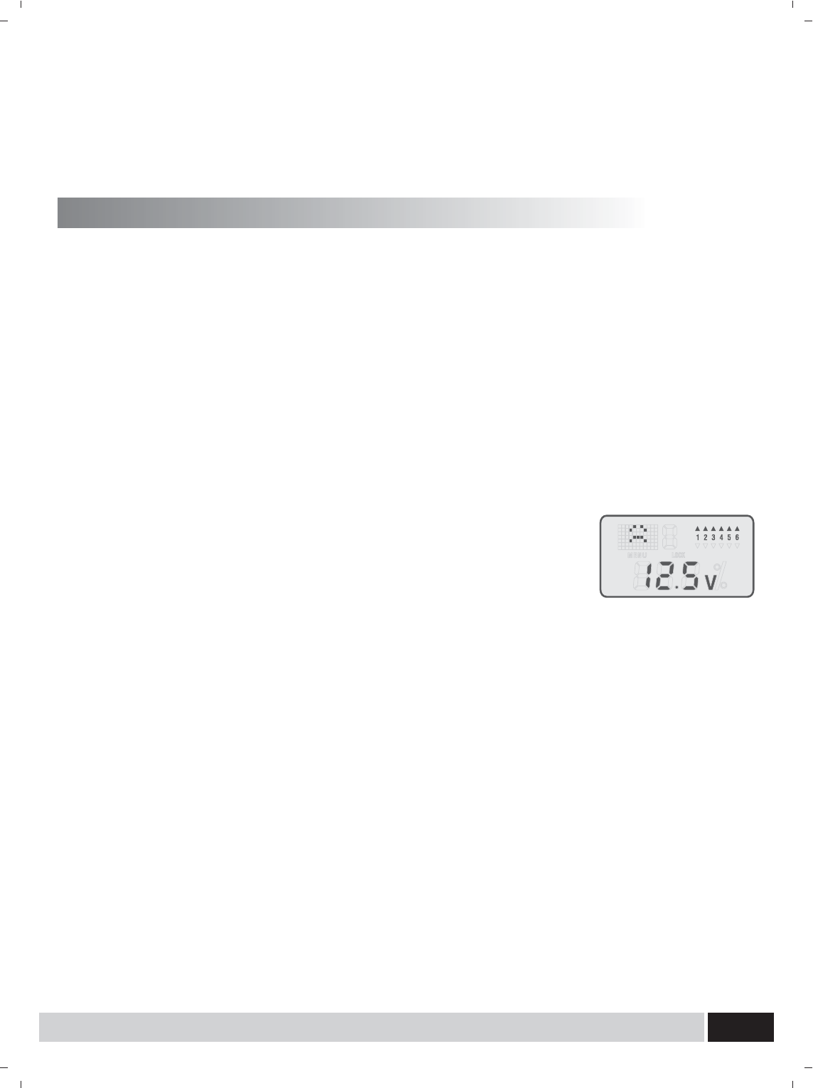
1. Flying time display: less than 1 minute seconds showed, more than 1 minute minutes showed.
2. Supply voltage display and low voltage alarm function: When the battery voltage is lower than 8.5V,
the red LED flashes, and alarm.
3. Channel output reverse set.
4. 5 kinds of aircraft modes to choose, 12 independent aircraft data storage and call.
5. Mode I and mode II exchange.
6. Throttle protection: in order to avoid danger of starting the motor of a
sudden, when throttle hold switch is turned on, throttle output value is the
minimum.
When boot, for various reasons (location of the assembly, curve setup),
throttle output value is not the minimum, the red LED flashes and alarm, as
shown in the figure. The throttle lose automatically locked out for a
minimum value, when the transmitter adjustment is appropriate (that is, the
throttle output is the smallest), the transmitter is unlocked.
7. Ch1 ch2 ch4 DR (Dual Rate) setting.
8. Ch1 ch2 ch4 EXP(exponential curve) setting.
9. All channel EPA (end of the process) setting.
10. Ch5 two-state setting (gyroscope sensitivity setting for helicopters, landing gear set up for fixed-
wing planes).
11. Ch3 ch6 general and 3D mode curve set for general helicopters and CCPM helicopters
12. 4 groups channel mixing control
13. All channel output dynamic display
14. All channel mid-point regulation
15. Restore the factory settings
16. Ch1 ~ Ch6 auxiliary fine-tuning settings
www.art-tech.com 03
Thanks for purchasing ETC62D-2.4GHz radio control set. For safe use, please read
this manual before using carefully. Any damage or loss to radio control set and model
due to inproper use will not be shouldered by Art-Tech.
www.art-tech.com
04
Servo: AS-100(9 g) 3pcs
Speed controller: ESC-30A
1pcs
Bettery packs: 9.6V/Ni-MH 1pcs
Charger:
1pcs
Specifications
Number of channels: 6
Charging jack: yes
3D switch: yes
Power supply: 12 V (1.5V * 8AA batteries)
We do not offer servo, speed controller, battery or changer with the radio control system .
Users can buy as spare parts.
Transmitter: ETC62D-2.4GHz
1pcs
Receiver: ER62-2.4GHz 1p c s
Simulator cable: 1pcs
Belt: 1pcs
Manual: 1pcs
CD: 1pcs
Contents:
Voltage Display: LCD
Color: Black
Antenna length: 15 cm
Using occasions: aircraft, helicopters
Certification: FCC, CE, RoHS
Notice for use
Please do not fly in the rain or strong wind. The
water can sink into the transmitter which can
cause out of control,leading to crash.
Pleas note before using, test the radio set first
and any change to the radio set or model can
cause crash.
Please do not fly near housing, road,airport or
power line
The transmitter can not work properly if the
frequency bind button is pressed down
neglectfully. In this case, The transmitter and
the receiver must be bind again. More details ,
Please refer to the process of frequency bind for
2.4 GHz R/C system.
Please do not turn on several RC devices and
bind them at the same time, bind only one set of
RC device at one time. The RC device should
not be stay in bind state for a long time.
Storage note
Show Logo Meanings
WARNING
CAUTION
Indications of Special signs
Attention
Notification before Using
Please pay more attention to signs in this manual and safety while using
▲Please do not place the radio control set in the below situation:
hot or cold(60℃above or -10℃below)
under the sunshine long time
moist condition
dusty place
vibration condition
▲long time without using, please pick up batteries from the bay and store in the dry condition.
▲It is forbidden to clean the radio control set with chemical solvent such as acetone
▲The over used dry batteries can not be dispatched anywhere. That should be stored in a non-metal
tool and dispatched by environment-protection department.
▲ It is strongly recommended to use chargeable battery for the transmitter with the hope of
environment-protection and cost-reducing.
While opening the transmitter,the joystick for throttle shoule be on idle;only opening the transmiiter
can connect the power to model.
In order to close the transmitter, the joystick for throttle should be o nidle . Disconnect t h e power of
model,and close the transmitter. The propeller mayc ause d amageif im proper operation.
Stop the motor while transmitter adjustment. Please pay attention to the motor during adjustment.It is
better to use transmitter ,receiver etc,together from ART-TECH.
Please do not do any change to transmitter, otherwise it can affect transmitter`s function.
I improper operation may cause injury or hurt
I improper operation may cause injury or hurt
www.art-tech.com 05
www.art-tech.com
06
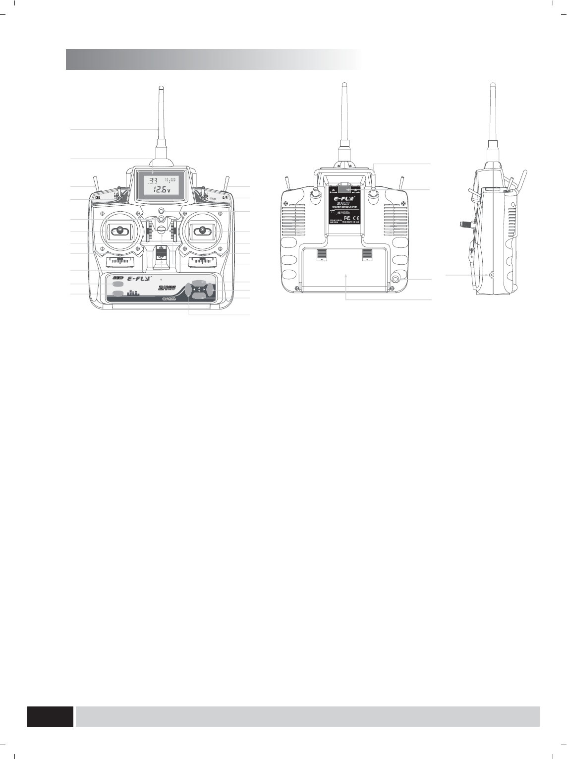
Transmitter particular introduce
A:Antenna
B:LCD(Liquid Crystal Display)
1)display battery voltage of transmitter
2)display whether the channels are reversed
3)display flying time
4)display menus
5) Display lock or unlock state
Display area
1)function display area
2)channels direction display area
3)data display area
4)option number display area
C:Throttle hold switch
D:Ch5 switch
This switch is for Ch5 that can be used for aerial
camera, collapsible landing gear and shift
between gyro mode and gyro gain, etc.
E:3D switch
F:D/R switch
G:Indicator LED for Power voltage
H:Red Indicator LED for low voltage alarm: When
battery voltage is under 8.5V, the LED will flash and
alarm; the LCD will cut off when voltage is under 7.6V。
Note: When red LED flashes or nothing shows on
LCD, please change the battery in order to avoid
flying out of control.
I:Joystick
1)If the transmitter is Mode 1,CH1 is for aileron
and CH3 for throttle.
2)If the transmitter is Model 2,CH1 is for aileron
and CH2 for Rudder
J:Joystick
1)If the transmitter is Model 1,CH2 is for elevator
and CH4 for rudder.
2)If the transmitter is Model 2,CH3 is for throttle and
CH4 for rudder.
K:Throttle trim lever (Mode 1)
Elevator trim lever (Mode 2)
1)If the transmitter is Mode 1,it is for Ch3
2)If the transmitter is Mode 2,it is for Ch1
L:Elevator trim lever (Mode 1)
Throttle trim lever (Mode 2)
1)If the transmitter is Mode 1,it is for Ch1
2)If the transmitter is Mode 2,it is for Ch3
M:Rudder trim lever
N:Aileron trim lever
O:Switch for Power
P:Flying Ring
Q:Menu Button
1) Enter into main menu
2) Enter into next main menu
3) Enter into time page menu (release after long
press)
R:Sub Button
1) Enter into sub menu
2) Enter into next sub menu
3) Enter into time page menu (release after long
press)
S:Y/UP
1) Selection validate
2) Data increase
3) Normal channel direction selects (release after
long press)
T:RIGHT Button, selection(right)
U:N /DOWN
1) Selection cancels
2) Data decrease
3) Reverse channel direction select (release after
long press)
V:LEFT Button, selection(left)
W:Steel Handle
X:Bind Button
Y:Plug for Simulator
Z:Battery bay for transmitter
A1:Rechargeable plug ( Note: Only 9.6V Ni-MH
battery pack can be recharged )
X
W
Z
YA1
LCD DIGITAL PROPORTIONAL RADIO CONTROL SYSTEM
MENU
LEFT RIGHT
Y/UP
N/DOWN
SUB
E
G
J
L
N
P
V
A
B
C
D
H
I
K
M
O
F
S
T
U
Q
R
ETC62-2.4GHz
www.art-tech.com 07
Menu introduction
After turn on the radio, the screen displays the time page. Press menu
several times to enter the required main menu, Press the sub button during
this period you can enter into the sub-menu of corresponding main menu.
In the menu operation, the success of the button operation will
accomplish with a prompt sound. If there is no prompt sound, maybe the
button is not in place or this button has no function in this menu. When the
special function button (y / up or n / down button) to confirm the
implementation of operation, there will be 3 prompt sounds; as for the
abolition of operation, there will be 3 demotion sounds. When menu setting
is complete, press the menu button or sub button for about 1 second you will
hear 2 prompt sounds, then release the button you will return to the time
page.
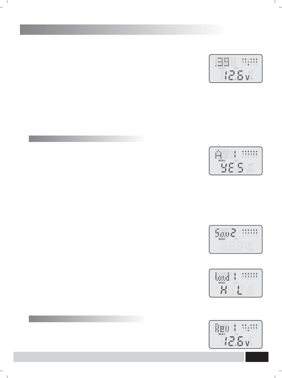
1. Press the menu button; enter into the data storage menu (Mode select
function).
2. Press the Left or right button, choose the right mode, press the y / up
button to confirm. (In the option number display areas the number of the
recently called file is displayed, as shown in Figure 1, the number of the
recently called file is the No.1 File. Yes means that the present chosen
mode is what is shown at the function display area, as shown in Figure,
the present chosen mode is A mode.) Of all the modes: A (aero plane
mode); V (V tail mode); C (CCPM helicopter mode); H(helicopter mode)
D(Delta plane mode)
1.2 Storage mode:
1. Press the sub button; enter into the mode menu (Save function).
2. Press the Left or right button, choose the right store location, press the y /
up button to confirm storage. You can store a total of 12 models.
1.3 Mode call:
1. Press the sub button; enter into the data call menu (Load function).
2. Press the Left or right button, choose a suitable stored location, press the
y / up button to confirm data call. (Note: Call will coverage the data value
being set now. non means no data has been stored in selected location.
As in Figure, H means in the storage location the model mode is
helicopter mode, L means Mode II and r means Mode I.)
1.1 Flying mode setting:
1. Mode selection
2. Servo Reversing settings
1. Press the menu button; enter into the Rev menu (Servo Reversing).
2. Press the Left or right button, choose a channel, press the y / up button to
change the Reversing setting.
www.art-tech.com
08
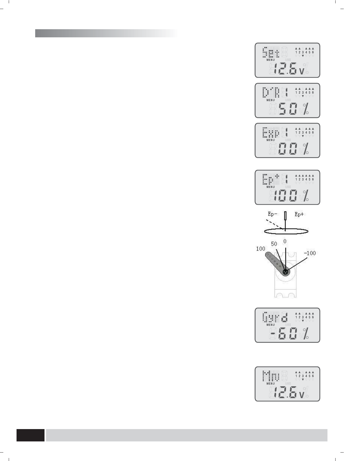
1. Press the menu button, enter into the Set menu. (There are 5 submenu
included: D'R, Exp, Epa, Gyr, Mrv)
3.1 D'R (Dual Rate) settings:
1. Press the sub button; enter into the D'R menu (Dual Rate Settings).
2. Press the Left or right button, choose a channel (aileron, elevator or
rudder), press the y / up or n / down button to increase or reduce the
value. The values set take effect when the D'R switch is switched on. The
Dual Rate exponential curve may be set anywhere between 0% and 125%
3.2.Exponential Settings:
1. Press the sub button; enter into the Exp menu (Exponential Settings).
2. Press the Left or right button, choose a channel (aileron, elevator or
rudder), press the y / up or n / down button to increase or reduce the value.
The exponential curve may be set anywhere between -100% and 100%)
3.3.EPA (End Point Adjustment):
1. Press the sub button; enter into the Ep menu (End Point Adjustment).
2. Press the Left or right button, choose a channel (minus signal means the
minus half part, while plus signal means the plus half part), press the y /
up or n / down button to increase or reduce the value. The values may be
set anywhere between -100% and 100%)
The Ep- is corresponding to one half trip of the stick, while the Ep+ is
corresponding to the other counterparts half. Reasonable settings of Ep
can achieve 3 point curve of any channel.
3.4 Gyroscope sensitivity / landing gear setting:
1. Press the sub button; enter into the Gyr menu (GYRO mixing).
2. Press the Left or right button, choose a channel (d means the CH5
switch is down, u means the CH5 switch is up), press the y / up or n / down
button to increase or reduce the value. The value may be set anywhere
between -100% and 100%)
3.5 Mixing Rate Settings
(A.V.D mode)
1. Press the sub button and enter the Mrv menu (Mixing Rate Settings).
2. Press the left or right button to choose the right option (A for aileron, E for
elevator, R for rudder). Press the y/up button or n/down button to
increase or decrease the setting value (The value -100%~100%
indicates the actual output mixing rate).
3. Popular options:
www.art-tech.com 09
Press the menu button, enter into the Cuv menu (there are 4 submenu
included: Thr, Pit, T3d, P3d). Switch on the 3D switch, the 3D curve can be
activated.
4.1 Normal Throttle settings:
1. Press the sub button; enter into the Thr menu (Normal throttle curve
function).
2. Press the Left or right button, choose the key point to be set (5 key
points are corresponding to the channel trip of 0% 25% 50% 75% 100%),
press the y / up or n / down button to increase or reduce the value. The
value may be set anywhere between 0% and 100%)
4.2 Normal pitch settings:
1. Press the sub button, enter into the Pit menu (Normal throttle curve function).
2. Press the Left or right button, choose the key point to be set (5 key
points are corresponding to the channel trip of 0% 25% 50% 75% 100%),
press the y / up or n / down button to increase or reduce the value. The
value may be set anywhere between 0% and 100%)
4.3 3D throttle settings:
1. Press the sub button; enter into the T3d menu (3D pitch curve function).
2. Press the Left or right button, choose the key point to be set (5 key
points are corresponding to the channel trip of 0% 25% 50% 75% 100%),
press the y / up or n / down button to increase or reduce the value. The
values set take effect when the 3D switch is switched on. The value may
be set anywhere between 0% and 100%)
4.4 3D pitch settings:
1. Press the sub button, enter into the P3d menu (3D pitch curve function).
2. Press the Left or right button, choose the key point to be set (5 key
points are corresponding to the channel trip of 0% 25% 50% 75%
4.Curve settings
(C mode)
1. Press the sub button to enter the Swash menu (Swash Rate Setting).
The following Figure (1) is 120° CCPM and Figure (2) is 90° CCPM.
Press y/up button or n/down button to choose to connect the aileron to
CH1 or CH6, elevator to CH2, Pitch to CH6 or CH1.
2. Press the left button or right button to choose the right option (A for
aileron, E for elevator, P for pitch). Press the y/up button or n/down
button to increase or decrease the setting value (The value -100% ~ 100%
indicates the actual output mixing rate).
(1) (2)
www.art-tech.com
10
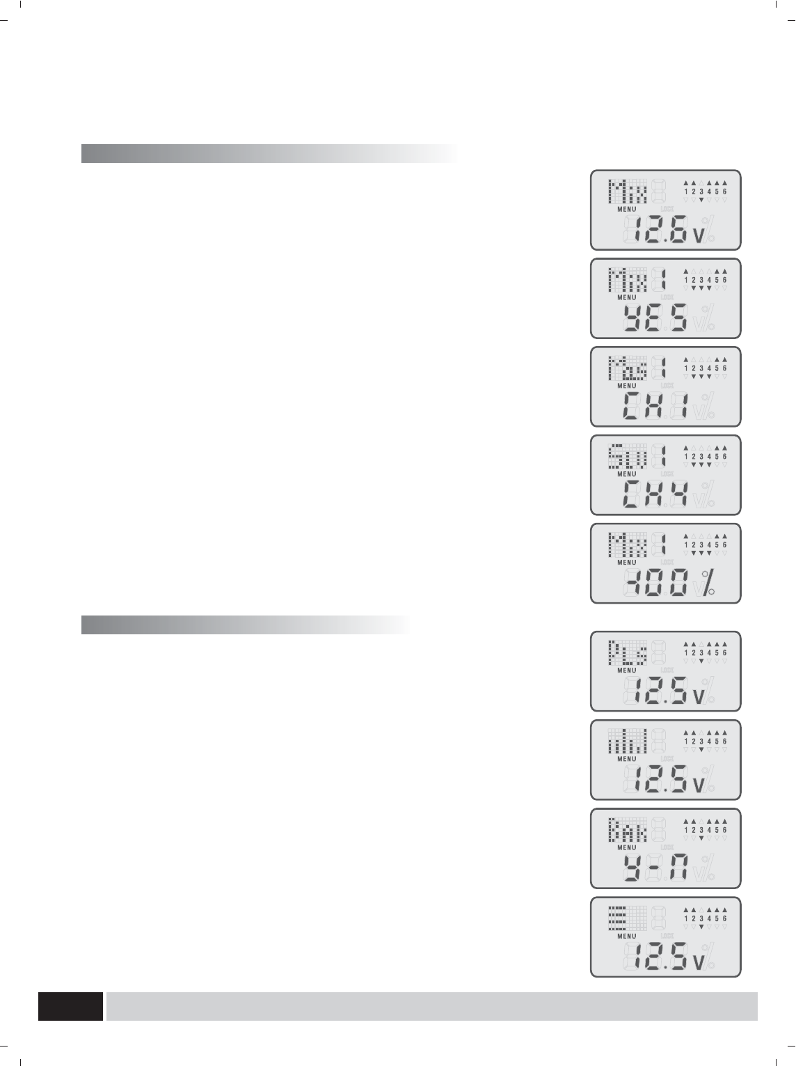
5.mixing settings (A, V, D mode)
6. Other function of the transmitter
Press the menu button, enter into the Mix menu (mixing).There are 2 sets of
mixing settings.
5.1 Mixing setting:
1. Press the sub button; enter into the Mix1 menu (mixing 1).
2. Press the Left or right button, choose the right option (whether to use
or not, the master channel, the slave channel, mixing proportion).
3. 1) Whether or not to use option: press y / up or n / down button to confirm
(YES) or cancel (NO).
2) Master channel option (Mas): press y / up or n / down button to select
the master channel.
3) Slave channel option (Slv): press y / up or n / down button to select the
slave channel.
4) Mixing proportion setting: y / up or n / down button to set the mixing
proportion. The slave channel is under control of the master channel at
the setting proportion. (The value may be set anywhere between 0% and
100%) Reasonable settings of MIX make flight of delta-wing or V-tail aircraft
which need the two-channel mixing control easy.
5.2 Mixing setting:
1. Press the sub button; enter into the Mix2 menu (mixing 2,3,4).
2. Specific settings are the same as Mix1.
Press the menu button; enter into the Pls menu (plus function).
6.1 Channel Display and Calibration:
1. Press the sub button, enter into the Chv menu (view of channels).
2. Press the Left or right button, choose a channel, the channel output
trip is displayed.
6.2.1 To restore the factory settings:
1. Press the sub button; enter into the Bak menu (back to original set).
2. Press the y / up or n / down button to confirm or cancel restore the
factory settings. Press the y / up button to confirm the resumption of the
factory settings.
6.2.2 Calibrate Settings:
Use at the first flight or the aircraft is changed) Press the y / up button, place
the sticks in the normal locations (Throttle channel minimum, other channels
middle), press the n / down button to confirm. (In this calibration process,
output values of all channels is the initial values)
1. Press the left or right button and enter the calibrate menu (calibrate Settings).
2. (
100%),press the y / up or n / down button to increase or reduce the value.
The values set take effect when the 3D switch is switched on. The value
may be set anywhere between 0% and 100%)
www.art-tech.com 11
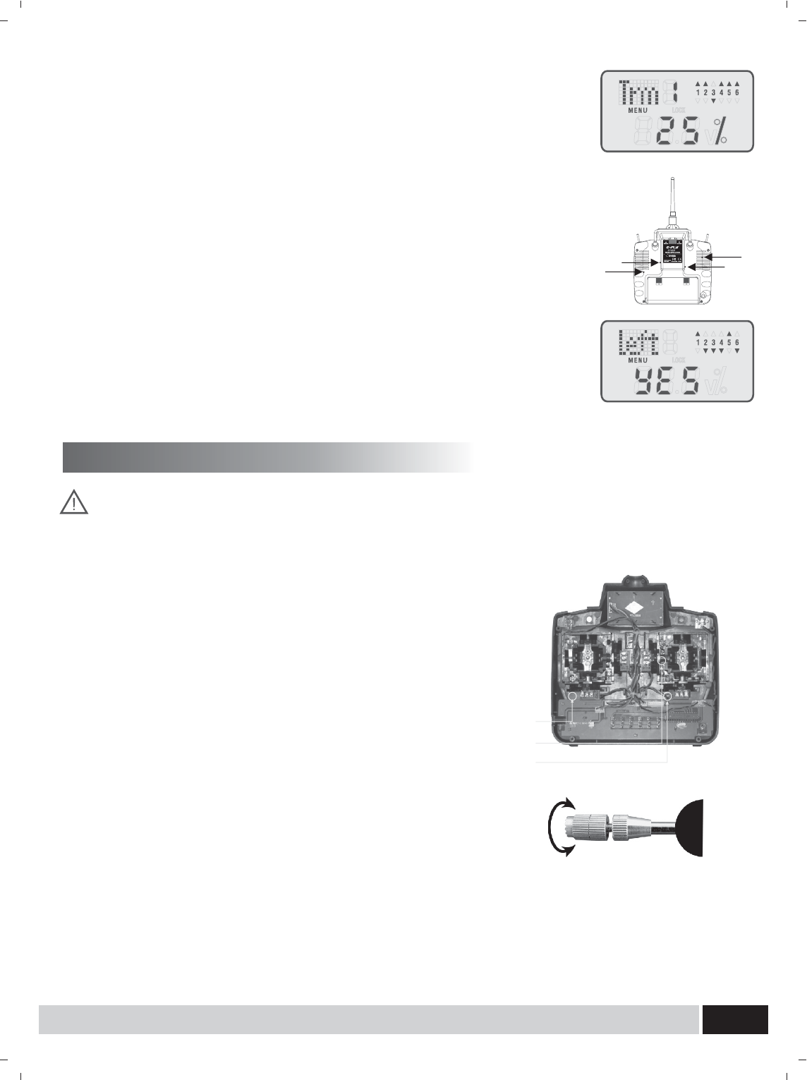
6.3 Auxiliary trim settings:
1. Press the sub button; enter into the Trm menu (Trim Settings).
2. Press the Left or right button, choose a channel.
6.4 Mode I and Mode II setting:
1. Press the sub button, enter into the Mode I and Mode II setting menu.
Before Mode Setting, please unplug the power supply of the plane.
Adjustment of joysticks The screws for mode setting are in the rear
cover. as shown in the figure: The screws A and B play the role of
suppressing springs; and the screws C and D play the role of adjusting
resist force. Therefore, for mode I, loosen the screws A and C, tighten
the screws B and D. For mode II, loosen the screws B and D, tighten
2. Press the Left or right button to choose the right mode and press the y /
up button to confirm. Left stands for Mode II, while right stands for Mode
I. After that you can process Channel calibration.
Alarm for low voltage of transmitter
Other function of the transmitter
When the voltage of transmitter battery is under working voltage,
the red LED will flash.It is better to stop flying,or that can cause
crash of model.
Operation for chargeable plug
The chargeable plus is on the side of transmitter,and it is specially designed
for charging the transmitter battery.Please note the batteries should be well
arranged in the bay and do not over charged
Adjustment for the joystick`s length
1.turn the head of joystick anticlockwise to prolong the length and deasil
for shorten the length Please note do not prolong too much.
2.tighten the lower part of the joystick anticlockwise Deasil to short
Anticlock to prdory
Adjustment on Joystick Spring
The joystick spring can be adjusted and it is possible to change that
for ailoren, elevator and rudder.
1.Turn the srew on the transmitter back anticlockwise, and open the back
2.turn the screw of the channel to adjust the spring, deasil for
stronger and anticlockwise for weaker.
3.close the back and turn the screw deasil screw adjustment
screw adjustment
screw adjustment
CAB
D
Operating voltage
Current drain:
Range(Height):
Adjacent channel rejection:
:4.8V~5.2V
≤40mA
Weight:12g
dimension:44mm*23mm*15mm
Channels: 6 Channels
≥350m
≥-85dBm± 16kHz
Receiver
Function
1.
2.
3.
4.
5.
6.
Undercarriage
Specifications
Rudder
Throttle
Elevator
Aileron
For operating helicopter
Operation for aeroplane
Pitch
B.Battery/Bind
1.
2.
3.
4.
5.
6.
Rudder
Throttle
Elevator
Aileron
Pitch
B.Battery/Bind
Gyro gain
Signal +-Signal +-
To make the receivers work normally, the input DC power should be stable and meet some requirements. The
input power is for receiver circuit and for servos.
The input voltage should be between 4.8V ~ 6V.
The working current is 0.25A of the receiver plus the current of servos.
Usually there are three ways for the receiver power supply:
1. Separate battery pack for the receiver.
2. Electronic speed controller with BEC (Battery Eliminate Circuit).
3. Dedicated receiver power supply distributor (UBEC).
If the flight model using this set of remote control device needs large manipulation force when flying, that is, in
case the servos may bear greater reaction and the work current of the servos is large, you need to pay more
attention to the receiver power supply stability in particular. Electricity supply equipment with good
performance is proposed to choose.
Power supply for the receiver
www.art-tech.com
12
RECEIVER
ER61-2.4GHz
CH
RECEIVER
ER61-2.4GHz
CH
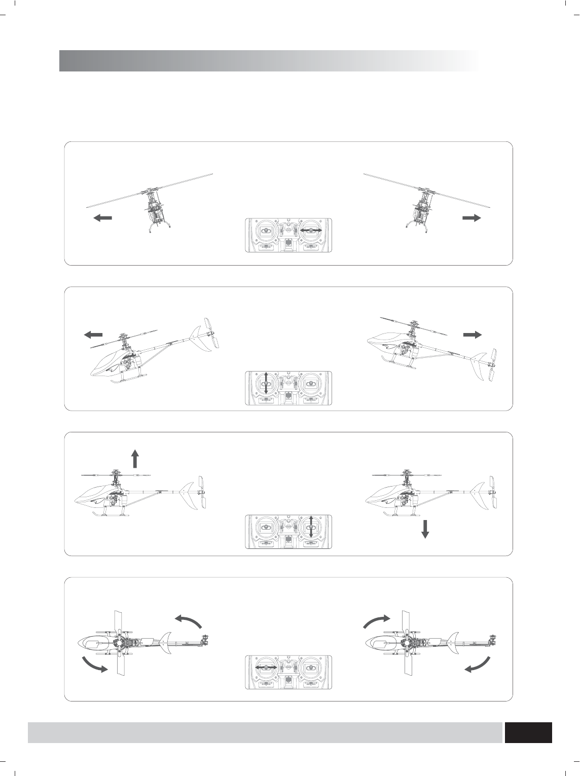
Operation for transmitter and servo
For operating helicopter
Rudder Operation
Joystick for Rudder left forward
the plane will turn anticlockwise
Joystick for Rudder right forward
the plane will turn deasil
Throttle Operation
Joystick is up forward,
the power becomes large
Joystick is down forward,
the power becomes small
Elevator Operation
Joystick for elevator up forward
tail is up,and plane will go
downforward
Joystick for elevator down forward
tail is down,and plane will go
upforward
Aileron Operation
Joystick for ailoren left forward
plane moves left
Joystick for ailoren right forward
plane moves right
Before adjusting, please be familiar with transmitter operation and servo(Below description in case of
all neutral)
(Mode 1)
www.art-tech.com 13

Operation for Rudder
Joystick for Rudder right forward,
rudder is right forward,
and the plane will turn
right and vice versa.
Operation for throttle
Joystick for throttle is down forward,
the power becomes small
Joystick for throttle is up forward,
the power becomes large
Elevator Operation
Climb upforward Operation
Joystick for elevator is down forward,
the elevator is up,and tail is down,
then the plane will climb up,
and vice versa
Aileron Operation
Joystick for ailoren righ forward
the right ailoren up and left ailoren
downand vice versa
Operation for transmitter and servo
Operation for aeroplane
Before adjusting, please be familiar with transmitter operation and servo(Below description in case of
all neutral)
(Mode 1)
www.art-tech.com
14
www.art-tech.com 15
4. Press frequency again to get it
rebound.The transmitter get into working mode.
bind button
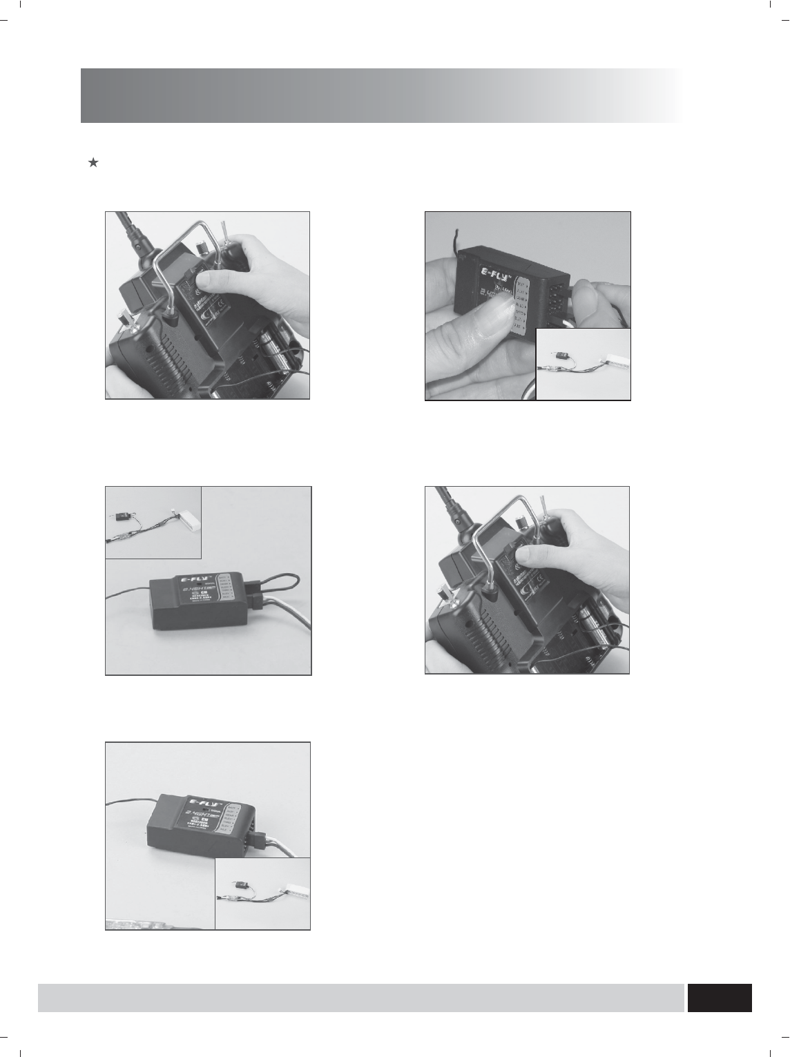
1. Press the frequency bind button, then
turn on the transmitter's power.
5. The indicator light turns bright again seconds
after pulling out the short-circuit plug, which
means that the radio system can work normally
now.
3. If the frequency is successful, the
indicator light will extinguish.
bind
2. Connect the ESC to receiver for electricity
supply, wihch results to the indicator light glitter.
And then plug the short-circuit plug into the
Receiver in the position of BATT.
If oil aircraft, please connect the power of receiver to other channel at first, and then plug it
to BATT after frequency bind.
The process of frequency bind for 2.4GHz R/C system
(Receiver with one antenna)
www.art-tech.com
16
If oil aircraft, please connect the power of receiver to other channel at first, and then plug it
to BATT after frequency bind.
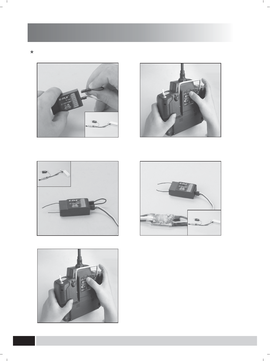
The process of frequency bind for 2.4GHz R/C system
(Receiver with two antenna)
4. Pulling out the short-circuit plug.the indicator
light turns flash. The rece iver get into working
mode.
2. Press the switch for frequency bind, then
turn on the transmitter's power.
5.
rebound.The transmitter get into working mode.
the indicator light will light.which means that the
radio system can work normally now.
Press frequency bind switch again to get it
3. If the frequency is successful, the
indicator light will light.
bind
1.
Receiver in the position of BATT.
the ESC to receiver for electricity supply,
wihch results to the indicator light glitter.
Plug the short-circuit plug into the
Connect
www.art-tech.com 17
Adjust order
Charge method of battery
Charge method:
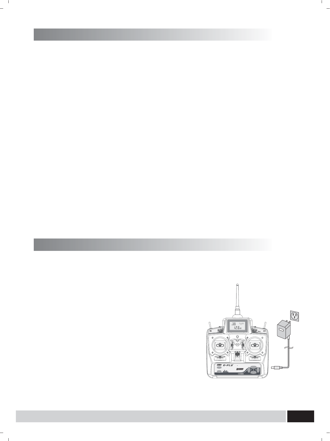
1.Turn off the transmitter, connect the transmitter with the charger in the kits
(Note: Please make sure the transmitter be off before charging, It will not charged unless it is off)
Open the battery bay, and range the 8 cells AAA battery into the battery bay, then close the bay.
1. enter into the Chv menu, press the Left or right button, check whether the channels are in the right
positions, at this time channel 1, 2 and 4 should be 0% ,the minimum value of channel 3 should be -100%,
and the maximum should be 100%. If curve setting values are changed, it should be the set
value. If the values are different Please adjust the channels mid points. (Strongly recommended for
the first use)
2. Check every servo's movement and make sure every movement of control arms and servo arms is
correct. If not, please enter into the Rev menu for reverse.
3. Check the centering position of aileron, elevator and rudder
Open the transmitter and connect the power to motor. Make sure every servo is in centering position
And check servo arm has a 90 angel with servo. Adjust the length of control rod, and check all control
Arm is in neutral position.
4. Adjustment for range
Check the movement range and the centering position of each servo. If the traveling range is not
accepted, it can be adjusted by the position of clevis on the servo arm.
5. Check the connection of ESC and Motor
Check the joystick for throttle movement is in accordance with motor. If not, it is can be adjusted by
reverse switch.
6. Check the tiny mix for every control horn.
ETC62-2.4GHz
LCD DIGITAL PROPORTIONAL RADIO CONTROL SYSTEM
MENU
LEFT RIGHT
Y/UP
N/DOWN
SUB
2. Check it the input voltage is same as the main voltage,
the plug the charger into the socket.
3. The charging time should be no more than 5 hours,
it should be recharged if it has been unused in long time.
Remark:
1. Only the 9.6V Ni-He rechargeable battery can be
charged, the dry cell should not be charged.
2. Order to prolong the life of battery, please do not
charge more than the required time.
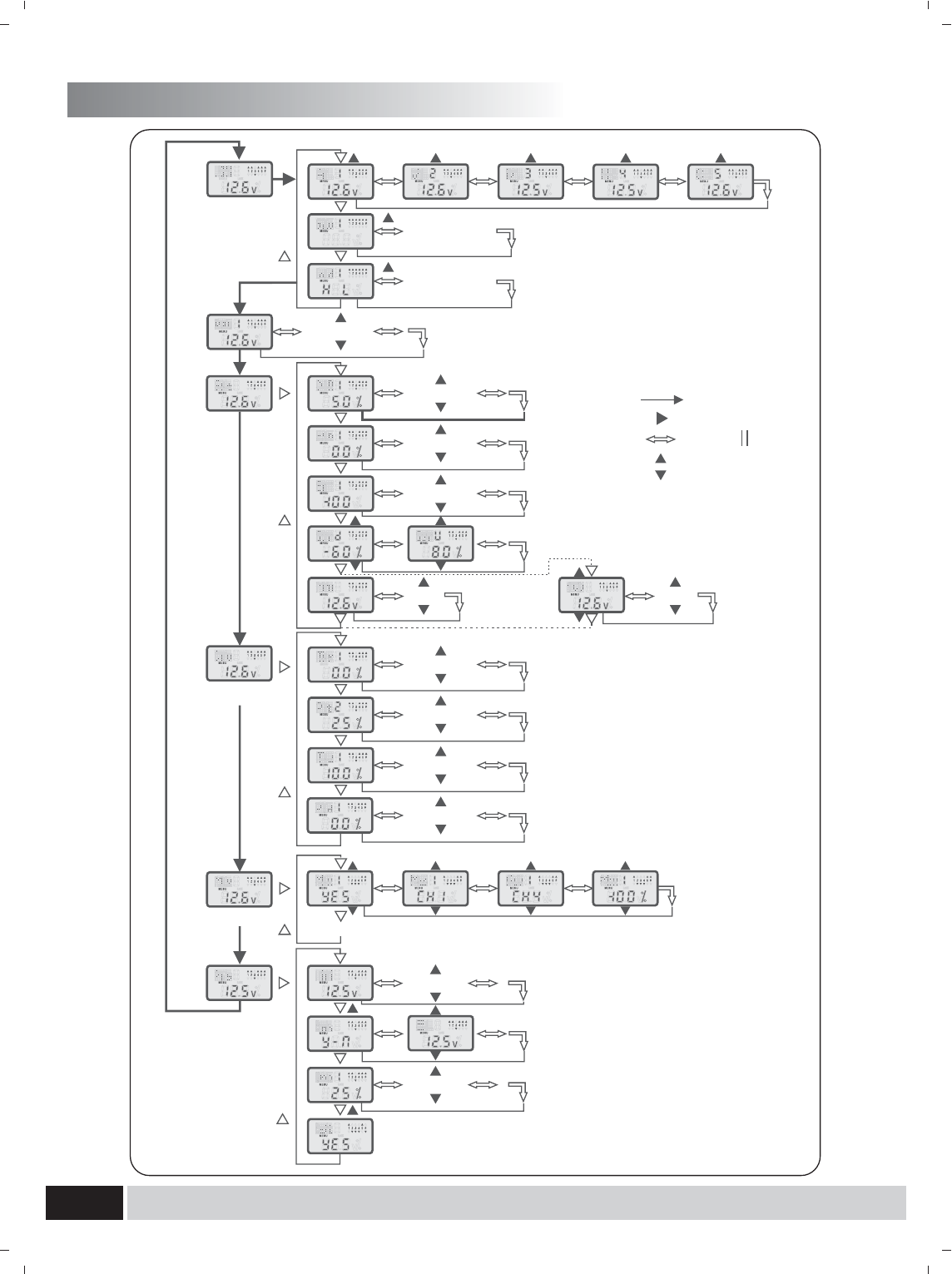
Flow list
www.art-tech.com
16
(1-9,A,b,C)
(CH1-6)
(CH1-6)
(CH1,2,4)
(CH1,2,4)
(PT1-5)
(PT1-5)
(PT1-5)
(PT1-5)
(H, C)
(A,V,D)
(CH1,2,4,6)
(CH1-6)
Key 图示
Menu
Sub
Left right
y/up
n/down
(1-9,A,b,C)
(Mix 2,3,4 Set as Mix 1)
(AEr),, (AEP),,
(C)
(A,V,D)
FCC Statement
This equipment has been tested and found to comply with the limits for a Class B digital device,
pursuant to part 15 of the FCC rules. These limits are designed to provide reasonable protection
against harmful interference in a residential installation. This equipment generates, uses and can
radiate radio frequency energy and, if not installed and used in accordance with the instructions,
may cause harmful interference to radio communications. However, there is no guarantee that
interference will not occur in a particular installation. If this equipment does cause harmful
interference
to radio or television reception, which can be determined by turning the equipment off and on, the
user is encouraged to try to correct the interference by one or more of the following measures:
-Reorient or relocate the receiving antenna.
-Increase the separation between the equipment and receiver.
-Connect the equipment into an outlet on a circuit different from that to which the receiver is
connected.
-Consult the dealer or an experienced radio/TV technician for help.
To assure continued compliance, any changes or modifications not expressly approved by the party
responsible for compliance could void the user’s authority to operate this equipment. (Example- use
only shielded interface cables when connecting to computer or peripheral devices).
FCC Radiation Exposure Statement
This equipment complies with FCC radiation exposure limits set forth for an uncontrolled
environment and it also complies with Part 15 of FCC RF Rules. Operation is subject to the
following two conditions:
1) This device may not cause interference and
2) This device must accept any interference, including interference that may cause undesired
operation of the device.
Caution!
The manufacturer is not responsible for any radio or TV interference caused by unauthorized
modifications to this equipment. Such modifications could void the user authority to operate the
equipment.
Declaration of Conformity
Hereby, ShenZhen ART-TECH R/C Hobby Co., Ltd., declares that this device is in compliance
with the essential requirements and other relevant provisions of Directive 1999/5/EC.