ShenZhen BiLian Electronic LW084-B IEEE 802.11b/g/n(1T1R) MINI PCI-E Module User Manual
ShenZhen BiLian Electronic Co.,Ltd. IEEE 802.11b/g/n(1T1R) MINI PCI-E Module
User Manual
Product Specification
Revision V1.0
Date 2016-07-16
Model Name BL-LW084-B
ProductName IEEE 802.11b/g/n (1T1R) MINI PCI-E Module
Bilian Approve Field
Engineer
QC
Sales
Customer Approve Field
Engineer
QC
Manufactory
Purchasing
Shenzhen Bilian Electronic Co.,Ltd
Address: No 268,Fuqian Rd.,JuTang Community ,Guanlan Town,Baoan District, Shenzhen, 518110,PRC
Homepage: www.b-link.net.cn

0
Table of Contents
Revision History .................................................................................................................................................. 1
1. Introduction ..................................................................................................................................................... 1
1.1 General Description ........................................................................................................................... 1
1.2 Features ............................................................................................................................................... 1
1.3 Applications ......................................................................................................................................... 2
2. Functional Block Diagram ............................................................................................................................... 2
3. ProductTechnicalSpecifications ...................................................................................................................... 2
3.1 General Specifications ....................................................................................................................... 2
3.2 DC Power Consumption .................................................................................................................... 3
3.3 RF Specifications ............................................................................................................................. 4
4. Pin Assignments .............................................................................................................................................. 5
5. Application Information ................................................................................................................................... 6
5.1 Supported Platform ............................................................................................................................ 6
6. Mechanical Specifications ............................................................................................................................... 6
7. Others............................................................................................................................................................... 7
7.1 Package Information .......................................................................................................................... 7
1
Revision History
Date Document
Revision
Product
Revision Description
2017/07/21 0.1 V0.1 Preliminary release
2017/08/19 1.0 V1.0 batch production
1. Introduction
1.1 General Description
BL-LW084-B product accord with FCC CE is a highly integrated Wi-Fi single chip which support 150Mbps
PHY rate. It fully complies with IEEE802.11n and IEEE802.11b/g standard, offering feature-rich wireless
connectivity at high standard, and delivering reliable, cost-effective throughput from an extended distance.
Optimized RF architecture and baseband algorithms provide superb performance and lower power
consumption. Intelligent MAC design deploys a high efficient DMA engine and hardware data processing
accelerators which offloads the host processor.
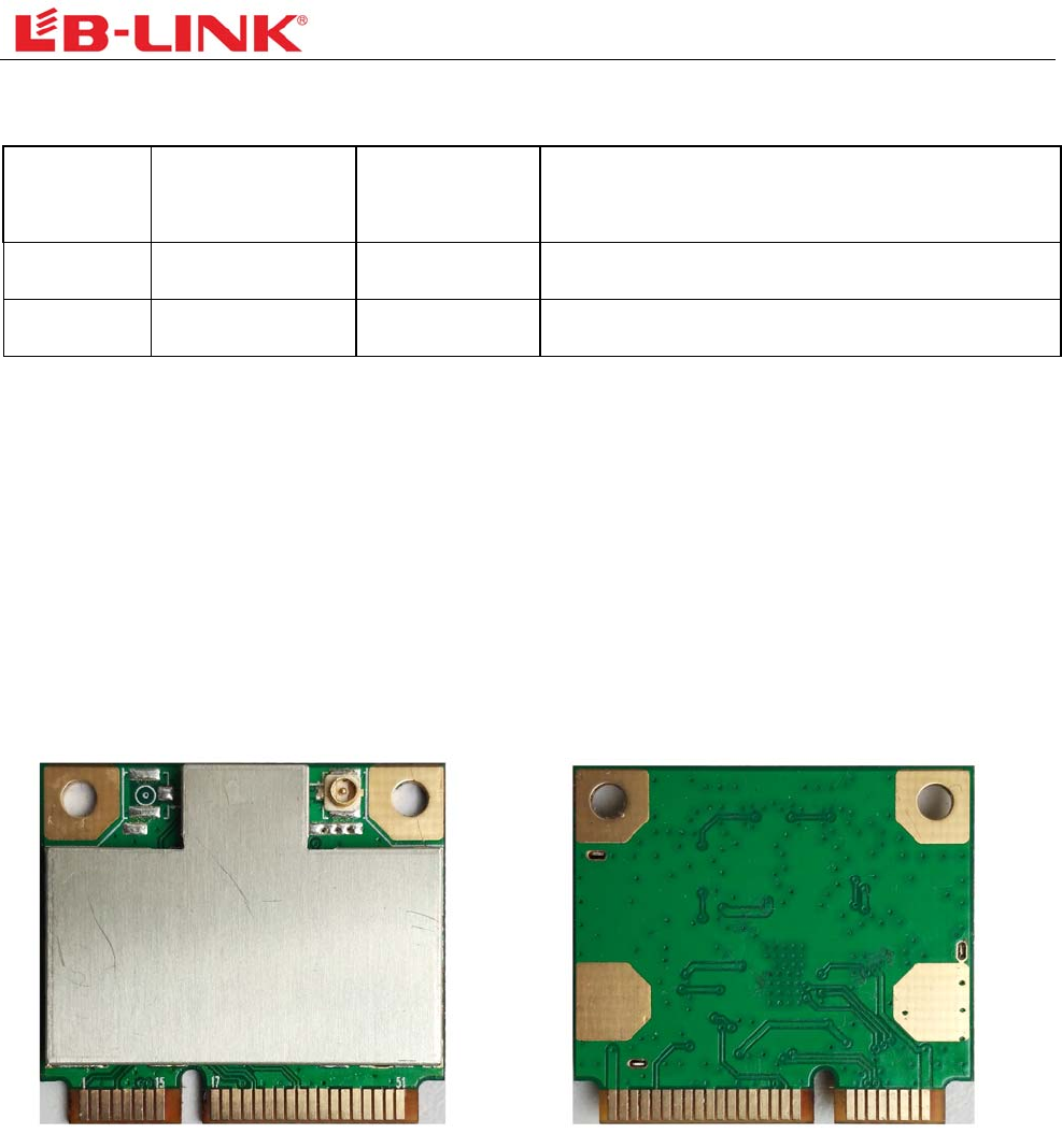
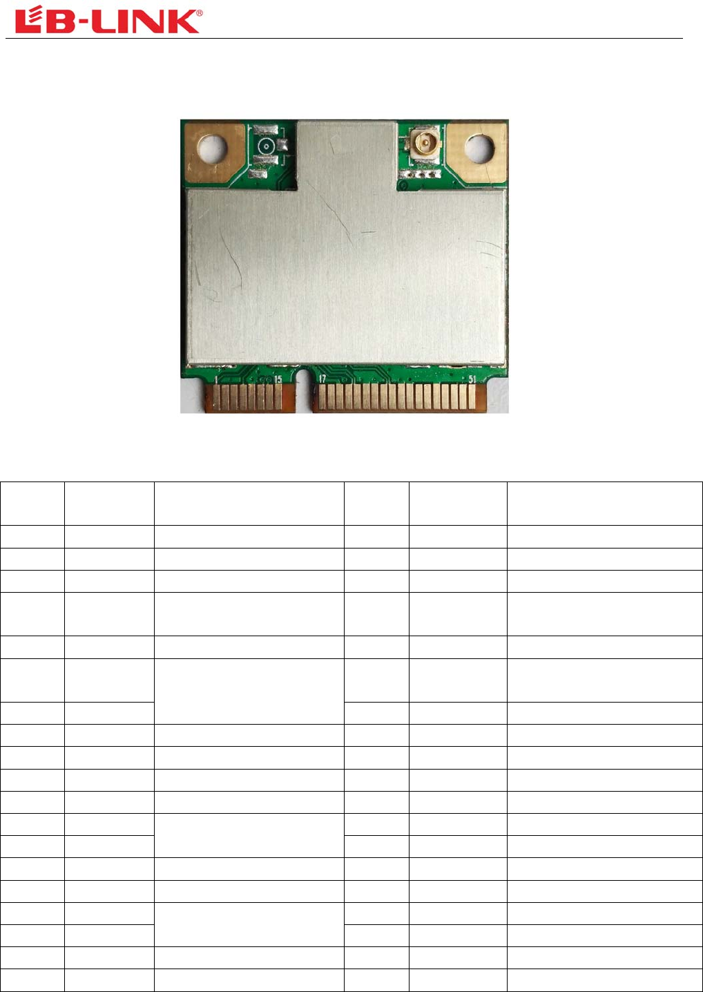
Figure1TopViewFigure2BottomView
1.2 Features
Operating Frequencies : 2.4~2.4835GHz
Host Interface is MINI PCI EXPRESS
IEEE Standards : IEEE 802.11b/g/n
Wireless data rate can reach up to 150Mbps
Connect to the external antenna through the IPEX connector
Power Supply:3.3V±0.2V
2
1.3 Applications
IP Camera
STB
Smart TV
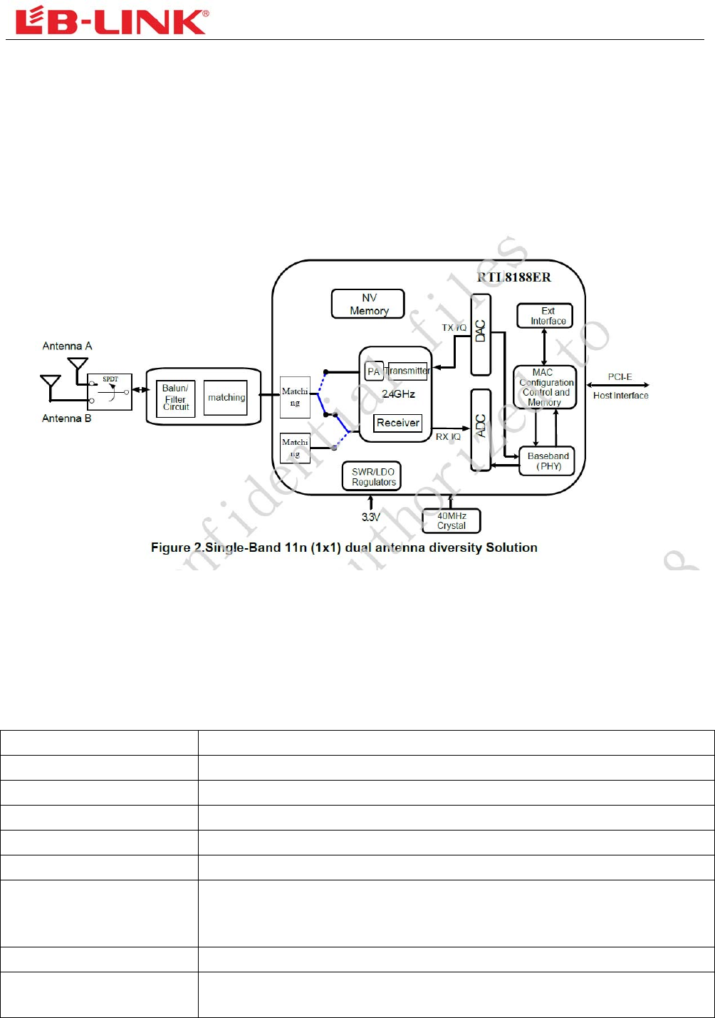
2. Functional Block Diagram
Figure3RTL8188EEblockdiagram
3. ProductTechnicalSpecifications
3.1 General Specifications
Item Description
Product Name BL-LW084-B
Main Chip RTL8188EE
Host Interface MINI PCI EXPRESS
IEEE Standards IEEE 802.11b, IEEE 802.11g,IEEE 802.11n
Operating Frequencies 2.4GHz~2.4835GHz
Modulation
802.11b: CCK, DQPSK, DBPSK
802.11g: 64-QAM,16-QAM, QPSK, BPSK
802.11n: 64-QAM,16-QAM, QPSK, BPSK
Working Mode Infrastructure, Ad-Hoc
Wireless Data Rate 802.11b: 1, 2 ,5.5,11 Mbps
802.11g: 6,9,12,18,24,36,48,54 Mbps
3
802.11n: MCS0~7,HT20 reach up to72.2Mbps, HT40 reach up to150Mbps
Rx Sensitivity -93dBm (Min)
TX Power 18dBm (Max)
Antenna Type Connect to the external antenna through the IPEX connector
Dimension(L*W*H) 30.0x 26.7x3.2mm (LxWxH),Tolerance: ±0.2mm
Power Supply 3.3V±0.2V
Power Consumption standby mode 40mA@3.3V (Max),
TX mode 180mA@3.3V (Max)
Clock Source 40MHz
Working Temperature -10°C to +50°C
Storage Temperature -40°C to +70°C
ESD CAUTION: Although this module is designed to be as robust as possible, Electrostatic Discharge (ESD)
can damage this module. It must be protected from ESD at all times and handled under the protection of ESD.
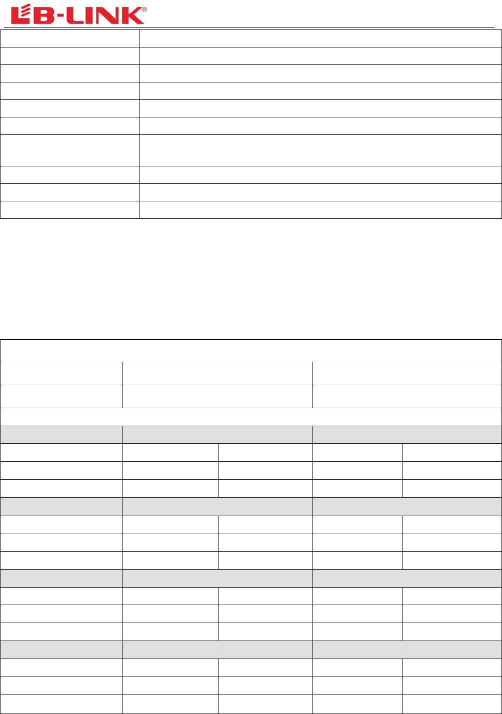
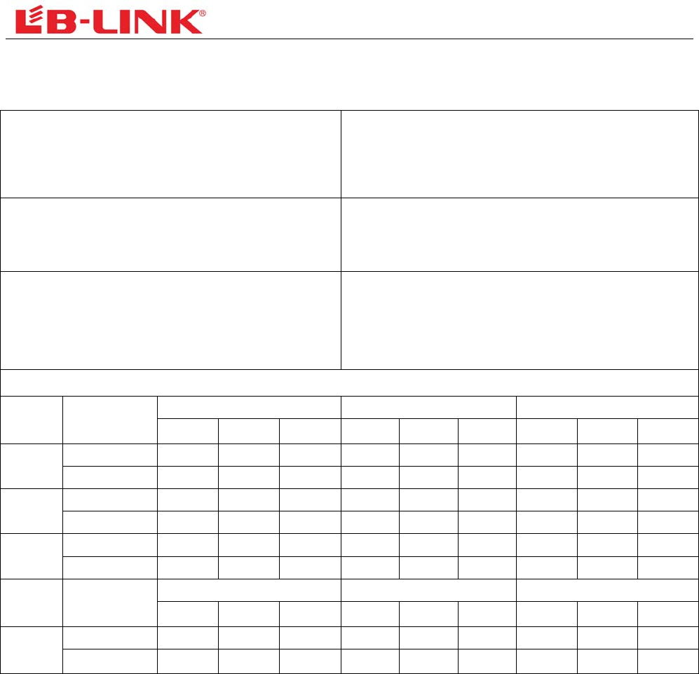
3.2 DC Power Consumption
Vcc=3.3V,Ta = 25 °C,unit: mA
Supply current Typ. Max
Standby (RF disabled) 35 40
802.11b 1Mbps 11Mbps
Supply current Typ. Max. Typ. Max.
TX mode 170 180 160 170
RX mode 30 35 35 40
802.11g 6Mbps 54Mbps
Supply current Typ. Max. Typ. Max.
TX mode 120 130 110 120
RX mode 30 35 35 40
802.11n HT20 MCS0 MCS7
Supply current Typ. Max. Typ. Max.
TX mode 100 110 90 100
RX mode 30 35 35 40
802.11n HT40 MCS0 MCS7
Supply current Typ. Max. Typ. Max.
TX mode 95 105 90 100
RX mode 30 35 35 40
4
3.3 RF Specifications
TX Power
802.11b: 17±1.5dBm
802.11g/11n-HT20: 14±1.5dBm
802.11n -HT40: 14±1.5dBm
TX Constellation Error(EVM)
802.11b: < -22dB@11Mbps
802.11g/11n-HT20: < -28dB@54/72.2Mbps
802.11n-HT40: < -28dB@135Mbps
Receiver Minimum Input Sensitivity@PER
802.11b: < -90dBm@PER<8%@1Mbps
802.11b: < -84dBm@PER<8%@11Mbps
802.11g: < -72dBm@PER<10%@54Mbps
802.11n: < -66dBm@PER<10%@135Mbps
RF Test Report
Mode Rate(Mbps) Power(dBm) EVM(dB) Sensitivity(dBm)
CH1 CH7 CH13 CH1 CH7 CH13 CH1 CH7 CH13
11b 1 17.27 17.45 17.64 -34.43 -34.02 -33.67 -93 -93 -93
11 17.55 17.57 17.55 -25.33 -25.84 -27.23 -86 -85 -85
11g 6 15.25 15.69 15.63 -32.62 -33.59 -31.35 -90 -90 -90
54 14.87 14.66 14.82 -32.49 -34.23 -33.61 -74 -74 -74
11n
HT20
MCS0 14.92 14.61 14.33 -32.38 -34.32 -34.66 -90 -89 -90
MCS7 14.32 14.27 14.19 -32.29 -33.96 -35.14 -70 -70 -70
Mode Rate(Mbps) Power(dBm) EVM(dB) Sensitivity(dBm)
CH3 CH7 CH11 CH3 CH7 CH11 CH3 CH7 CH11
11n
HT40
MCS0 14.86 14.51 14.63 -31.37 -32.08 -32.42 -88 -88 -88
MCS7 14.35 14.05 14.27 -31.67 -31.95 -34.00 -67 -67 -67
5
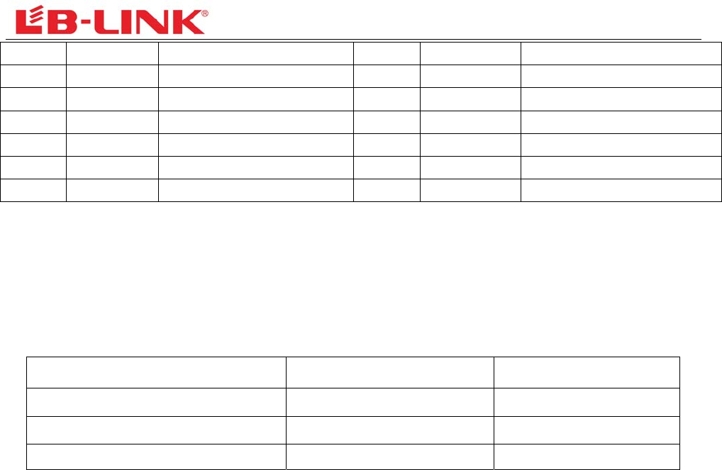
4. Pin Assignments
Figure4Pin Assignments(Topview)
PinNo PinName Description PinNo PinName Description
1 WAKE Wake / sleep control 2 VD33 DC 3.3V Power input
3 Reserved Reserved 4 GND Ground
5 Reserved Reserved 6 Reserved Reserved
7 CLKREQ# Reference clock request
signal
8 Reserved Reserved
9 GND Ground 10 Reserved Reserved
11 REFCLK- PCI Express Differential
reference clock signal
12 Reserved Reserved
13 REFCLK+ 100MHz ± 300ppm 14 Reserved Reserved
15 GND Ground 16 Reserved Reserved
17 Reserved Reserved 18 GND Ground
19 Reserved Reserved 20 W_DISABLE Radio signal control
21 GND Ground 22 PERST Reset signal (low level)
23 HSON PCI Express Differential
transmission signal
24 Reserved Reserved
25 HSOP 26 GND Ground
27 GND Ground 28 Reserved Reserved
29 GND Ground 30 Reserved Reserved
31 HSIN PCI Express Differential
transmission signal
32 Reserved Reserved
33 HSIP 34 GND Ground
35 GND Ground 36 Reserved Reserved
37 GND Ground 38 Reserved Reserved
6
39 Reserved Reserved 40 Reserved Reserved
41 Reserved Reserved 42 Reserved Reserved
43 GND Ground 44 LED_WLAN LED pin (active low)
45 Reserved Reserved 46 Reserved Reserved
47 Reserved Reserved 48 Reserved Reserved
49 Reserved Reserved 50 GND Ground
51 Reserved Reserved 52 VD33 DC 3.3V Power input
5. Application Information
5.1 Supported Platform
Operating System CPU Framework Driver
WIN2000/XP/VISTA/WIN7 X86 Platform Enable
LINUX2.4/2.6 ARM, MIPSII Enable
WINCE5.0/6.0 ARM ,MIPSII Enable
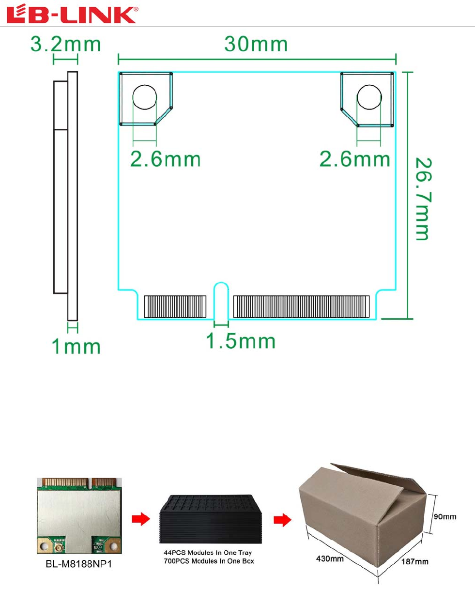
6. Mechanical Specifications
Module dimension: Typical ( L*W * H): 30.0mm*26.7mm*3.2mm Tolerance : +/-0.2mm
7
Figure5TopView
7. Others
7.1 Package Information
Figure6PackageInformation
8
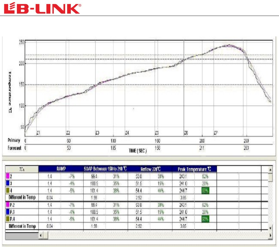
8. TypicalSolderReflowProfile
1. Pls handle the module under ESD protection.
2. Reflow soldering shall be done according to the solder reflow profile. Peak temperature
245℃.
3.Products require baking before mounting if humidity indicator cards reads >30% temp <30 degree C, humidity
< 70% RH, over 96 hours.
Baking condition: 125 degree C, 12 hours
Baking times: 1 time
4. Storage Condition: Moisture barrier bag must be stored under 30 degree C, humidity under 85% RH. The
calculated shelf life for the dry packed product shall be a 12 months from the bag seal date. Humidity
indicator cards must be blue, <30%.
9
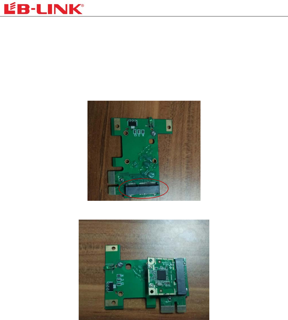
9. installation
1. product should not collocate with other radio
2. host label should content modular FCC ID:2AL6K-LW084-B
3. If you buy this module, you use should be satisfied for the antenna:
(a)the antenna type:connect to the external antenna through the IPEX connector
(b)the antenna gain:≤2dBi
4.installation
(a)find the client mainboard’s router interface:as shown on the following picture.
(b)the module insert the mainboard according to the requirements of customers,pay attention to the position
(c)finished

FCC Statement
This equipment has been tested and found to comply with the limits for a Class B digital device,
pursuant to Part 15 of the FCC Rules. These limits are designed to provide reasonable
protection against harmful interference in a residential installation. This equipment generates
uses and can radiate radio frequency energy and, if not installed and used in accordance with
the instructions, may cause harmful interference to radio communications. However, there is
no guarantee that interference will not occur in a particular installation. If this equipment does
cause harmful interference to radio or television reception, which can be determined by turning
the equipment off and on, the user is encouraged to try to correct the interference by one or
more of the following measures:
-- Reorient or relocate the receiving antenna.
-- Increase the separation between the equipment and receiver.
-- Connect the equipment into an outlet on a circuit different from that to which the receiver is
connected.
-- Consult the dealer or an experienced radio/TV technician for help.
This device complies with part 15 of the FCC Rules. Operation is subject to the following two
conditions:(1) This device may not cause harmful interference, and (2) this device must accept
any interference received, including interference that may cause undesired operation.
Changes or modifications not expressly approved by the party responsible for compliance
could void the user's authority to operate the equipment.
This equipment complies with FCC radiation exposure limits set forth for an uncontrolled
environment. This equipment should be installed and operated with minimum distance 20cm
between the radiator & your body.