ShenZhen SolidRF Communications SR13652001 3 band consumer cell phone booster for building only User Manual PowerPoint
ShenZhen SolidRF Communications Co., Ltd 3 band consumer cell phone booster for building only PowerPoint
User Manual
Connect the world
www.SolidRFCanada.com 1
SOHO Tri Bands
Cellular Signal Booster
R3U01 User Manual
Features
•Works on AT&T 2G/3G/4G, Verizon 3G, T-Mobile 2G/3G/4G, Sprint 3G/4G, US Cellular 3G/4G, Metro PCS
3G/4G, All other Canadian Carriers 2G/3G, Major carriers using 850 MHz and 1900 MHz
•Allows multiple mobile devices to be used simultaneously
•Greatly reduces dropped calls, extends signal range, and increases data rates
•High integration semiconductor circuits design, internal integration inside antenna easily install
•Reduces radiation and extends battery life up to 2 hours additional talk time in weak signal areas
•Oscillation (or interference) detection and automatic shutdown
•Overload protection circuit – protects cell towers from being overloaded
•Power control logic ensures that maximum gain is within cellular standards
•Amplifies signal both to and from the cell tower
•Maximum 1 watts(EIRP) output power
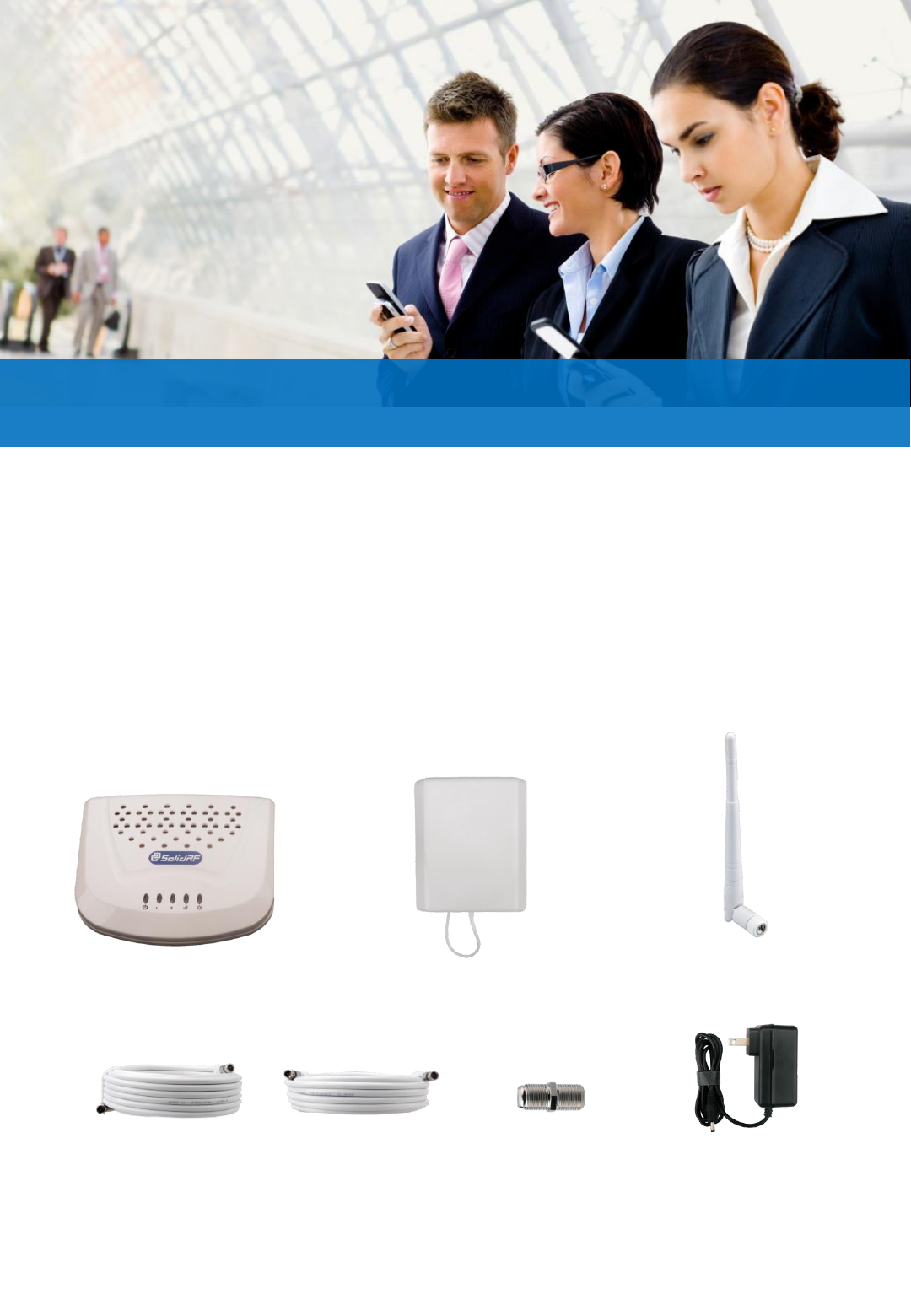
Package Contents
Booster Inside Unit Outside Antenna
&Booster Outside Unit
Power Adapter
Cable 30feet Cable 15feet Connector F-F to F-F
Technical Support: support@solidrf.ca
Inside Antenna
Installation 1
www.SolidRFCanada.com 2
1.How it works
Step 1: The powerful outside antenna captures a voice and
data signal, and transfer it to the booster;
Step 2: The booster receives the signal, amplifies it and
rebroadcasts it by inside antenna.
Step 3: Your mobile devices get a better signal, never
experience dropped calls or slow data speed.
2. Step by step installation
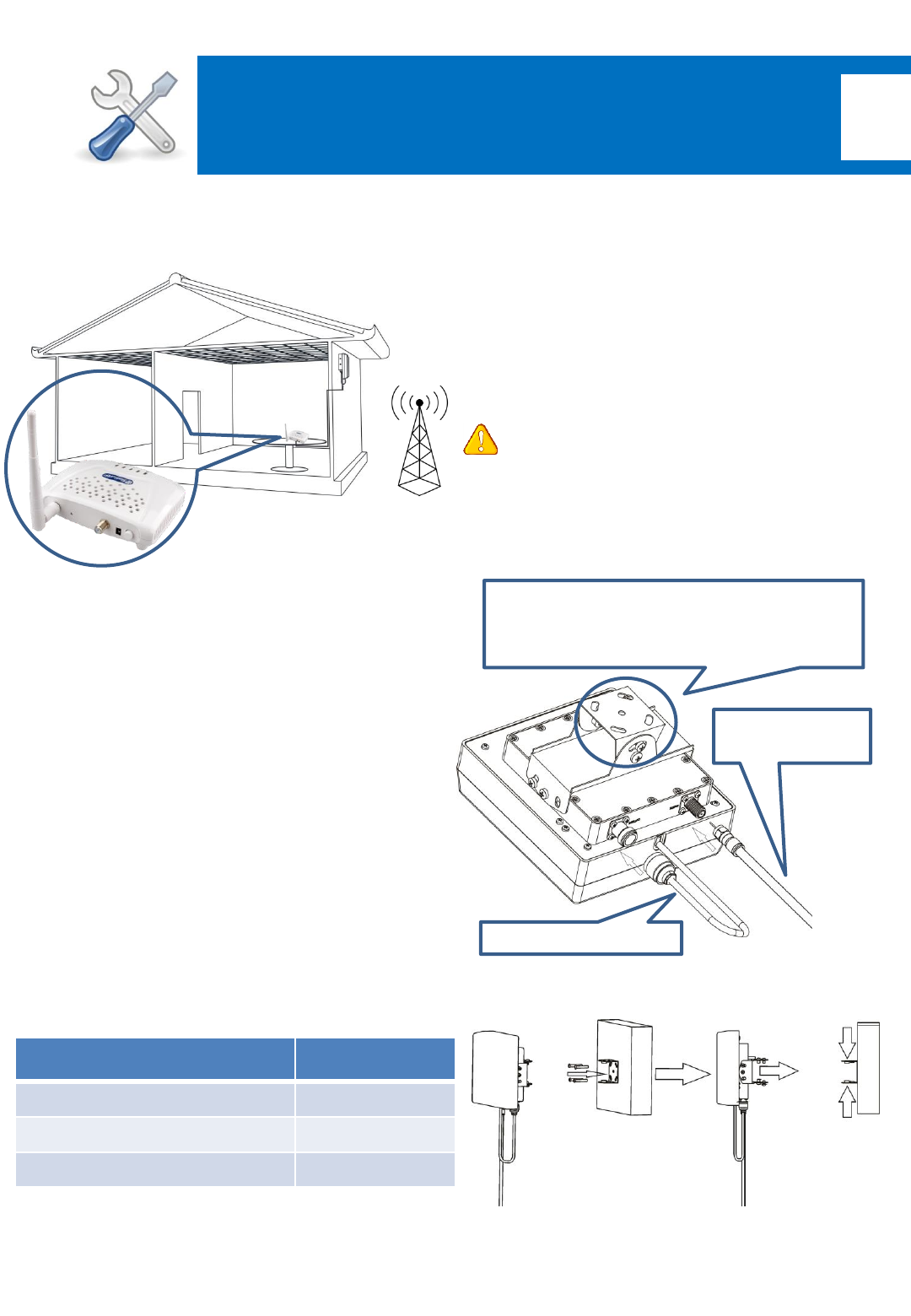
Step 1: mount the outside antenna& outside booster unit
Choose right position
•Find the strongest signal position in the possible install l
ocations by reading your cell phone signal bar;
•30cm away from any other metallic objects;
•100cm away from any windows;
1.2 Mount the antenna;
1.1 Connect the cables as required.
•Outside booster unit is designed integrated with outside
antenna to improve system performance;
•Make sure connectors are screwed well;
Coverage Area
Note: the ability of coverage depends on the output power
of booster. Any boost has a limit of the amplification factor,
so final output power is related to received signal power
level at the location of the outdoor antenna..
Power level
at the outdoor antenna location
Coverage Area
(sq. ft.)
Strong (5 bars on the cellphone) 3000
Medium (3~4 bars on the cellphone) 1200
Weak (1~2 bars on the cellphone) 300
Technical Support: support@solidrf.ca
Caution: Don’t face the outside antenna to the
direction of where the booster you plan arrange;
Supported Carriers
•AT&T 2G/3G (HSPA+), 4G on 850, 1900 and 700
MHz(Band 12)
•Verizon 3G
•T-Mobile 2G/3G, 4G on 850, 1900 and 700 MHz(Band 12)
•Sprint 3G/4G
•US Cellular 3G
•Metro PCS 3G/4G
•Major Canadian Carriers 2G/3G
•All other carriers using 850 MHz,1900 MHz and 700 MHz
Outside cable
to booster
Antenna to booster
Indicate the direction of best signal and
adjust the angle of the antenna
accordingly
www.SolidRFCanada.com 3
Installation 2
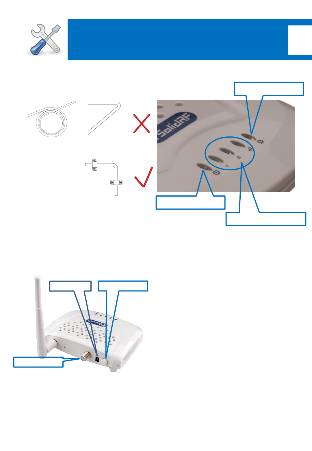
1.3 Set the outside antenna cable into the building
•Carefully arrange the cable along the building outside
and make sure don’t fold it or roll up;
•Fix the cable at each corner;
2.3 Connect the outside antenna’s connector to the “ANT2”
port of the booster;
2.4 Connect the inside antenna to the “ANT1” port;
Step 3: power on the booster
a. Plug the power adapter to the AC power;
b. Attach the cord of the adapter to the booster and switc
h on;
Step 2: arrange the inside unit
2.1 Choose right position
•20cm away from any other metallic objects;
2.2 50cm away from any windows;
•Be sure away from heat source;
•In ventilate dry place, temperature range should
0~+50degree;
Outside antenna
Adapter cord Power Switch
Technical Support: support@solidrf.ca
1. Power on LED(green)
3. Panel information
2. Signal level LED(green)
3. Alert LED(red or green)
1. Power on LED: whenever the booster is powered on,
this LED will be lighting on in green color;
a. If none of these LED is lighting: no signal received from
the base station tower. Here you can get no service;
b. One LED on: outside signal is weak and you can get 300
square feet up coverage;
c. Two LED on: outside signal is middle and you can get
1200 square feet up coverage;
d. Three LED on: outside signal is strong and you can get
3000 square feet up coverage;
2. Signal level LED: indicated how strong the signal have
been received from the outside antenna.
3. Alert LED: indicate booster condition;
a. Every time the booster is power on it will light on for a
second in red color and then switch off;
b. Stable red color on: the installation of the outside
antenna and the inside booster’s location is no
suitable(face to each other or too close) and need to
be relocated;
c. Stable green color on: the cable from the inside unite to
outside unite isn’t connected correctly;
d. Stable off: the booster is working well;
www.SolidRFCanada.com 4
Installation 3
Note3: Don’t cover the booster body with
anything, in case the power dissipation make the
booster too high temperature. The booster will shut
down when the temperature is too high itself.
Note2: Use only the power supply provided by
SolidRF, any other products non-approved by
SolidRF or self-made power cable may damage the
booster.
Note4: Troubleshooting
•Properly: when the “power on LED” and “signal level
LED” are lighted, the “Alert LED” is off (no phone
calling and pads communicating) or flashing
(someone on the phone call). The booster is in good
condition;
•Wrong condition: any time the “Alert LED” in stable
red color or green color, please check the installation
by following this manual again.
Technical specification
Frequency
(MHz)
Cellular (band 5) PCS (band 2) Band 12/ Band 17
Uplink 824-849 1850-1910 698-716
Downlink 869-894 1930-1990 728-746
Gain Uplink 60±2 65±2 60±2
Downlink 61±2 68±2 61±2
Output power 23±2dBm(Uplink)/0±2dBm(Downlink)
Noise figure <3dB
In-band Flatness <5dB
Weight 0.7Kg
EIRP 1W
Gain adjustment 20dB
Impedance 50 ohm
Operating
temperature
-20°~50°
Current ≦1.5A(12V DC)
Dimension(mm) 155*125*25
Technical Support: support@solidrf.ca
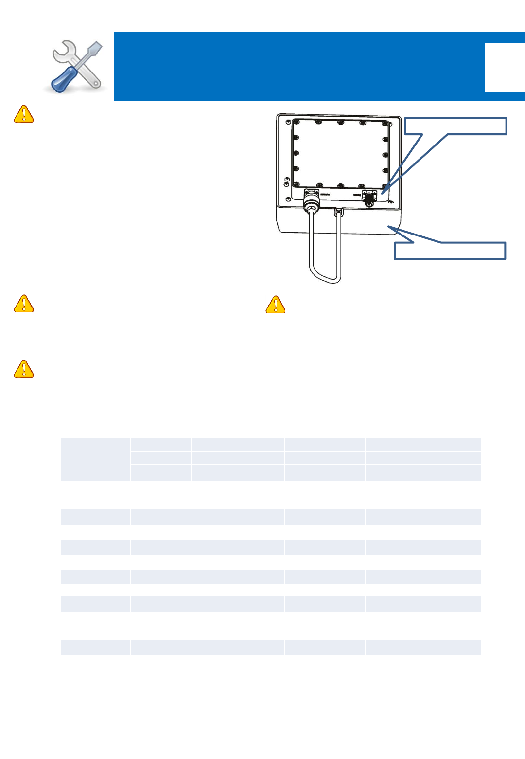
Note1: about the outside antenna and
outside booster unit
The outside antenna and outside booster
unit are integrated design, both them are
waterproofed design. No matter rain or
frog, they will work properly. But extreme
temperature maybe causes problem to the
booster unit, it will work perfectly from -
20℃ to +55 ℃ temperature range. Too high
or low temperature beyond that range will
cause self-protection, the booster will
lower down output power to avoid damage.
Outside booster unit
Outside antenna
www.SolidRFCanada.com 5
Warnings and Recommendations
Warning: This consumer booster is for Consumer use only.
Warning: Unauthorized antennas, cables, and/or coupling devices are prohibited by FCC
regulations. Please contact FCC for details: 1-888-CALL-FCC.
Warning: Outside antenna orientation must be back side of inside antenna is to prevent the indoor
antenna receiving the signal emitted by outside antenna. Otherwise it will cause self-oscillation of
booster.
Warning: RF safety, any antenna used with this device must be located at 20 cm (8 inches) away
from persons or by bystanders.
Warning: It will damage the mobile device and the booster if connect them with a cable directly.
Warning: Use the power supply provided by SolidRF only. Other power supplies may cause damage
of the booster.
Warning: Antenna installation is restricted to 10 meters or less height above ground, even if the
antenna is installed inside when used with a mobile device that operates in the 1710-1755 MHz
band. Violation of this requirement may subject the owner of the booster to potential FCC
enforcement actions.
Warning: Never point the front of a directional antenna toward the inside antenna. Verify that
both the outside antenna and the inside antenna are connected to the booster before powering up
the booster.
Description of network protection features:
This booster including safeguards to protect the cellular network from interference. Each Signal
Booster is individually tested and factory set to ensure FCC compliance.
1. The Signal Booster cannot be adjusted without factory reprogramming or disabling the hardware.
2. The Signal Booster will amplify, but ONLY incoming and outgoing signals in order to increase
coverage of authorized frequency bands.
3. If the Signal Booster is not in use for five minutes, it will reduce gain until a signal is detected.
4. If a detected signal is too high in a frequency band, or if the Signal Booster detects an oscillation,
the Signal Booster will automatically turn the power off on that band.
5. For a detected oscillation the Signal Booster will automatically resume normal operation after a
minimum of 1 minute. After 5 times consecutive such automatic restarts, if the detected
oscillation still remains, any problematic bands are permanently shut off until the Signal Booster
has been manually restarted by reconnecting power supply to the Signal Booster.
6. Noise power, gain, and linearity are maintained by the Signal Booster’s microprocessor.
This is a CONSUMER device
BEFURE USE ,you MUST REGISTER THIS DEVICE with your wireless provider and have
your provider’s consent .Most wireless provider consent to the use of signal boosters
.Some provider may not consent to the use of this device on their network .If you are
unsure, contact your provider.
You MUST operate this device with approved antenna and cables as specified by the
manufacturer .Antennas MUST be installed at least 20cm (8inches) from any person.
You MUST cease operating this device immediately if requested by the FCC or a licensed
wireless service provider.
WARNING.E911 location information may not be provided or may be inaccurate for calls
served by using this device.
This device may be operated ONLY in a fixed location for in-building use.

www.SolidRFCanada.com 6
This device complies with Part 15 of FCC Rules. Operation is subject to the following two
conditions: (1) this device may not cause harmful interference, and (2) this device must accept
any interference received, including interference that may cause undesired operation.
This equipment has been tested and found to comply with the limits for a Class B digital device,
pursuant to Part 15 of the FCC Rules. These limits are designed to provide reasonable protection
against harmful interference in a residential installation. This equipment generates and can
radiate radio frequency energy and, if not installed and used in accordance with the instructions,
may cause harmful interference to radio communications. However, there is no guarantee that
interference will not occur in a particular installation. If this equipment does cause harmful
interference to radio or television reception, which can be determined by turning the equipment
off and on, the user is encouraged to try to correct the interference by one or more of the
following measures:
-- Reorient or relocate the receiving antenna.
-- Increase the separation between the equipment and receiver.
-- Connect the equipment into an outlet on a circuit different from that to which the receiver is
connected.
-- Consult the dealer or an experienced radio/TV technician for help
Contact information for providers
A subscriber must have the consent of a wireless provider to operate a consumer signal booster.
Please register your booster with your wireless service provider, refer to contact information for
providers:
Sprint:
signalbooster@sprint.com
T-Mobile:
www.T-Mobile.com/BoosterRegistration
https://support.t-mobile.com/docs/DOC-9827
Verizon:
http://www.verizonwireless.com/wcms/consumer/register-signal-booster.html
AT&T:
https://securec45.securewebsession.com/attsignalbooster.com/
U.S. Cellular:
http://www.uscellular.com/uscellular/support/fcc-booster-registration.jsp
Metro PCS
https://www.metropcs.com/support/signal-booster