ShenZhen Zhongherong Electric Technology SZESKY003 Remote Control Toy Transmitter User Manual II
ShenZhen Zhongherong Electric Technology Co., Ltd. Remote Control Toy Transmitter II
Contents
- 1. User Manual I
- 2. User Manual II
User Manual II

When the throttle stick is pushed downward.
the speed of the motor and main rotor
increases, as a result, the helicopter descends.
When the throttle stick is pushed upward,
the speed of the motor and main rotor
increases, as a result, the helicopter lifts up.
When the aileron stick is moved to the
right, the swashplate also tilt to the right,
and the helicopter moves to the right.
When the aileron stick is moved to the left,
the swashplate also tilt to the left, and the
helicopter moves to the left.
2
Model 2 (left throttle)
2.4G
2.4G TRANSMITTER INSTRUCTION MANUAL
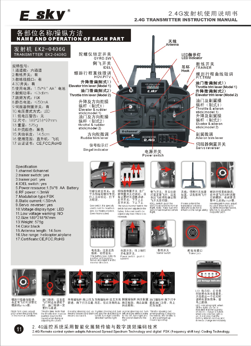
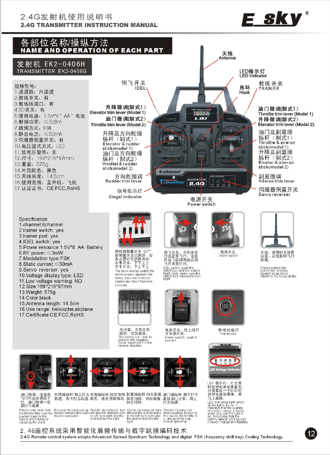
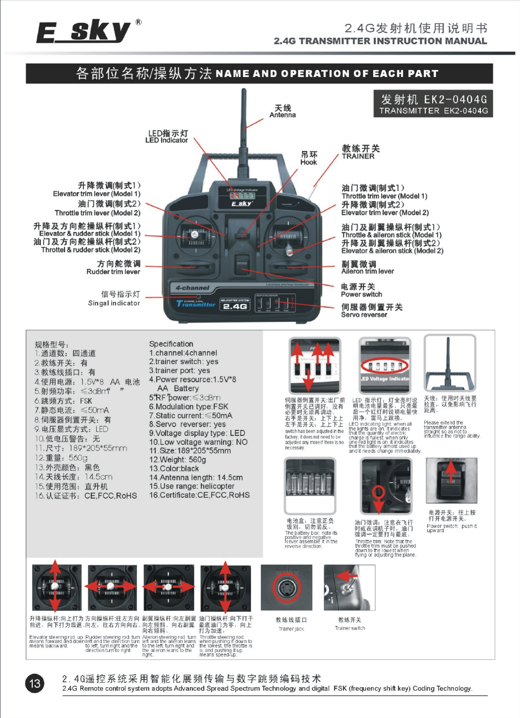
92.4G Remote control system adopts Advanced Spread Spectrum Technology and digital FSK (frequency shift key) Coding Technology.
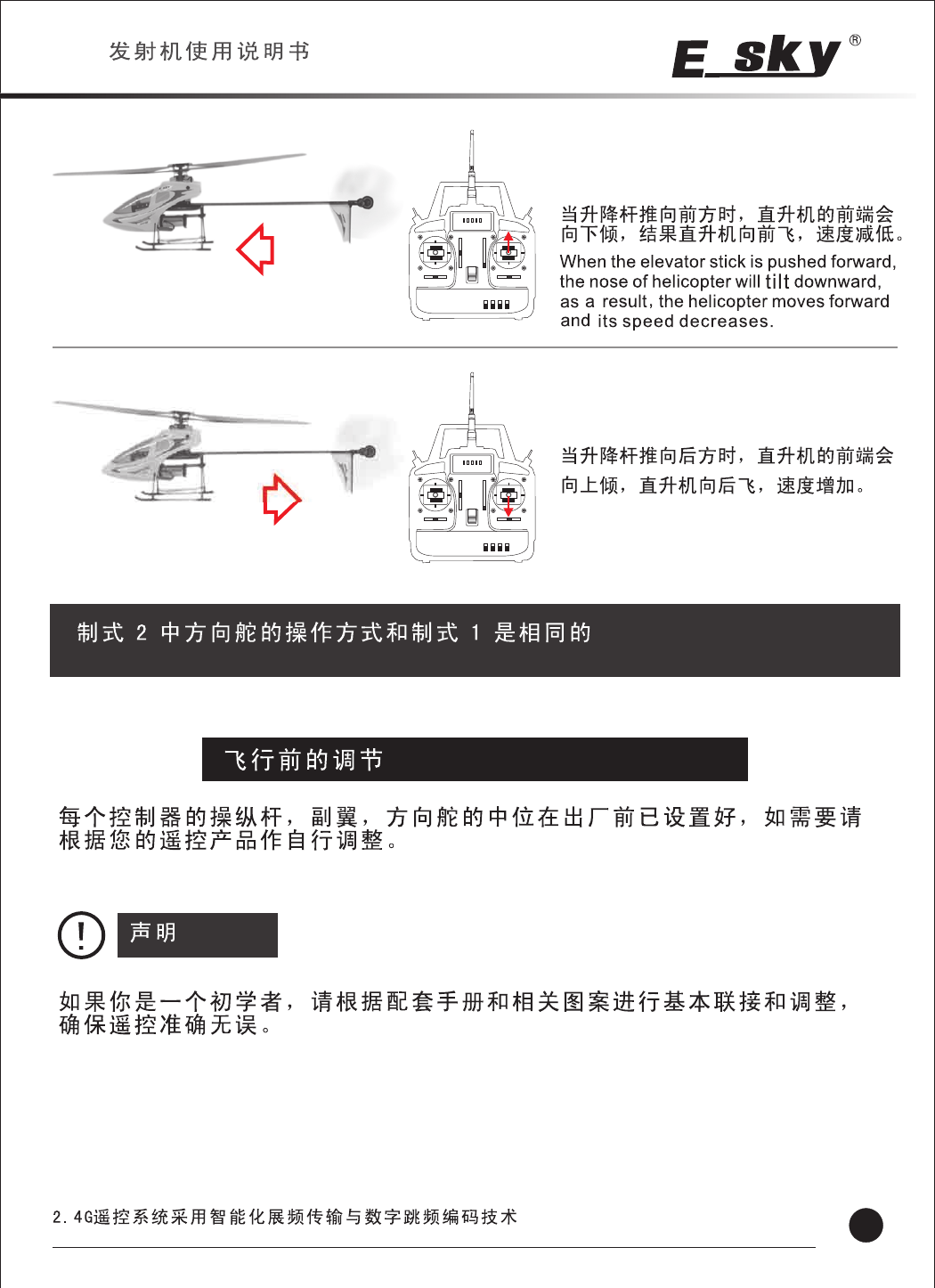
The rudder stick operation for Model 2 is the same as Model 1
When the elevator stick is pushed backward,
the nose of the helicopter will tilt upward,
then the helicopter moves backward and
its speed increases.
ADJUSTMENTS BEFORE FLYING
The meso-position of each operating stick, aileron and rudder had already set in the factory, you can adjust
it according to your needs. If need adjustment ,you can adjust according to your remote products.
If you are a novice ,please connect and adjust each part according to the corresponding manual and
pictures to ensure the proper operation.
Caution
2.4G
2.4G TRANSMITTER INSTRUCTION MANUAL
10
2.4G Remote control system adopts Advanced Spread Spectrum Technology and digital FSK (frequency shift key) Coding Technology.
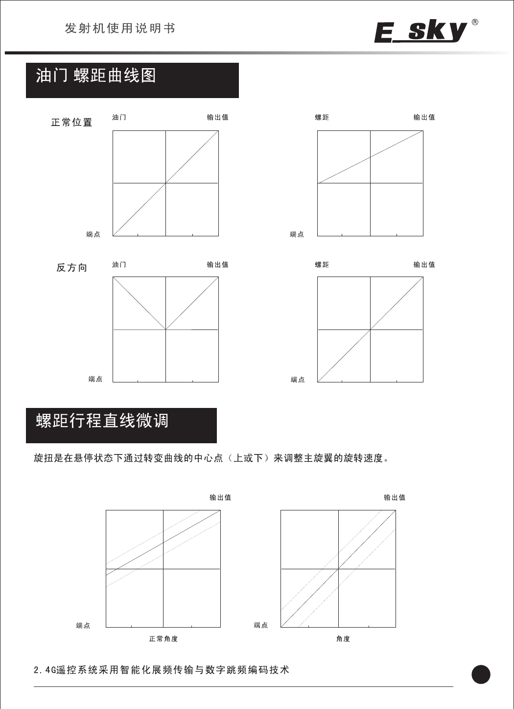
NOR
IDEL UP
THR
Endpoint
Output Value
123HL
0%
50%
100%
PIT Output Value
123HL
0%
50%
100%
123HL
THR Output Value
0%
50%
100%
123HL
PIT Output Value
0%
50%
100%
Throttle/pitch curve diagram
/
Hovering Pitch knob
1 2 3 HL 1 2 3 HL
0%
50%
100%
0%
50%
100%
Output Value Output Value
3D
The hovering pitch knob function is to shift the center point of curve either upward or downward to adjust
totor RPM at the hover position.
NOR Pitch 3D Pitch
Endpoint
Endpoint Endpoint
Endpoint Endpoint
2.4G
2.4G TRANSMITTER INSTRUCTION MANUAL
2.4G Remote control system adopts Advanced Spread Spectrum Technology and digital FSK (frequency shift key) Coding Technology. 14
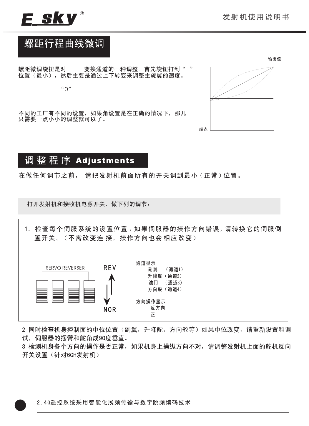
PITCH TRIM KNOB
PITCH 0
Point
Output Value
123HL
0%
50%
100%
The pitch trim knob is a trimmer for the pitch channel .This knob
should be set to at first ,then adjust the rotor RPM by shifting
it upward or downward.
As the setting of each manufacturer is different ,only small trim
adjustment will be required if the pitch curve had set properly.
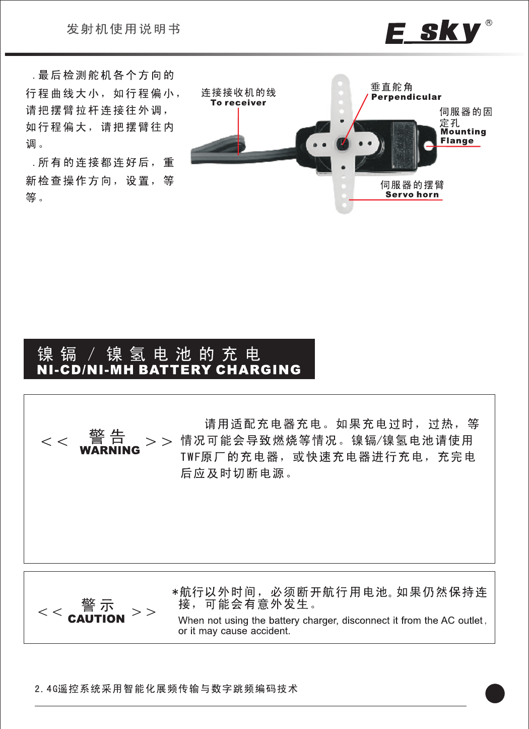
Before any adjustment, please set all the switches in the front of the transmitter to the lowest(normal)
position.
Turn on the power switch of the transmitter and the receiver , then make the following adjustments:
THRELEAIL RUD
AIL :
ELE:
THR:
RUD:
REV:
NOR:
Channel display
AIL : Aileron(channel 1)
ELE: Elevator(channel 2)
THR: Throttle(channel 3)
RUD: Rudder servo(channel 4)
Rudder operating display
REV: Reverse
NOR: Normal
Check the direction of each servo, If a servo operates in the wrong direction, switch its SERVO
REVERSR switch (the direction of operation can be changed without changing the linkage.)
2.Check the aileron, elevator and rudder neutral adjustment, if the neutral position changed,please reset
and readjust it ,make the servo horn to be perpendicar to the servo.
3.Check to see whether the operation of each direction is normal, if not ,please adjust the SERVE
REVERSERswitch (For 6CH transmitter ).
2.4G
2.4G TRANSMITTER INSTRUCTION MANUAL
15 2.4G Remote control system adopts Advanced Spread Spectrum Technology and digital FSK (frequency shift key) Coding Technology.
4
5
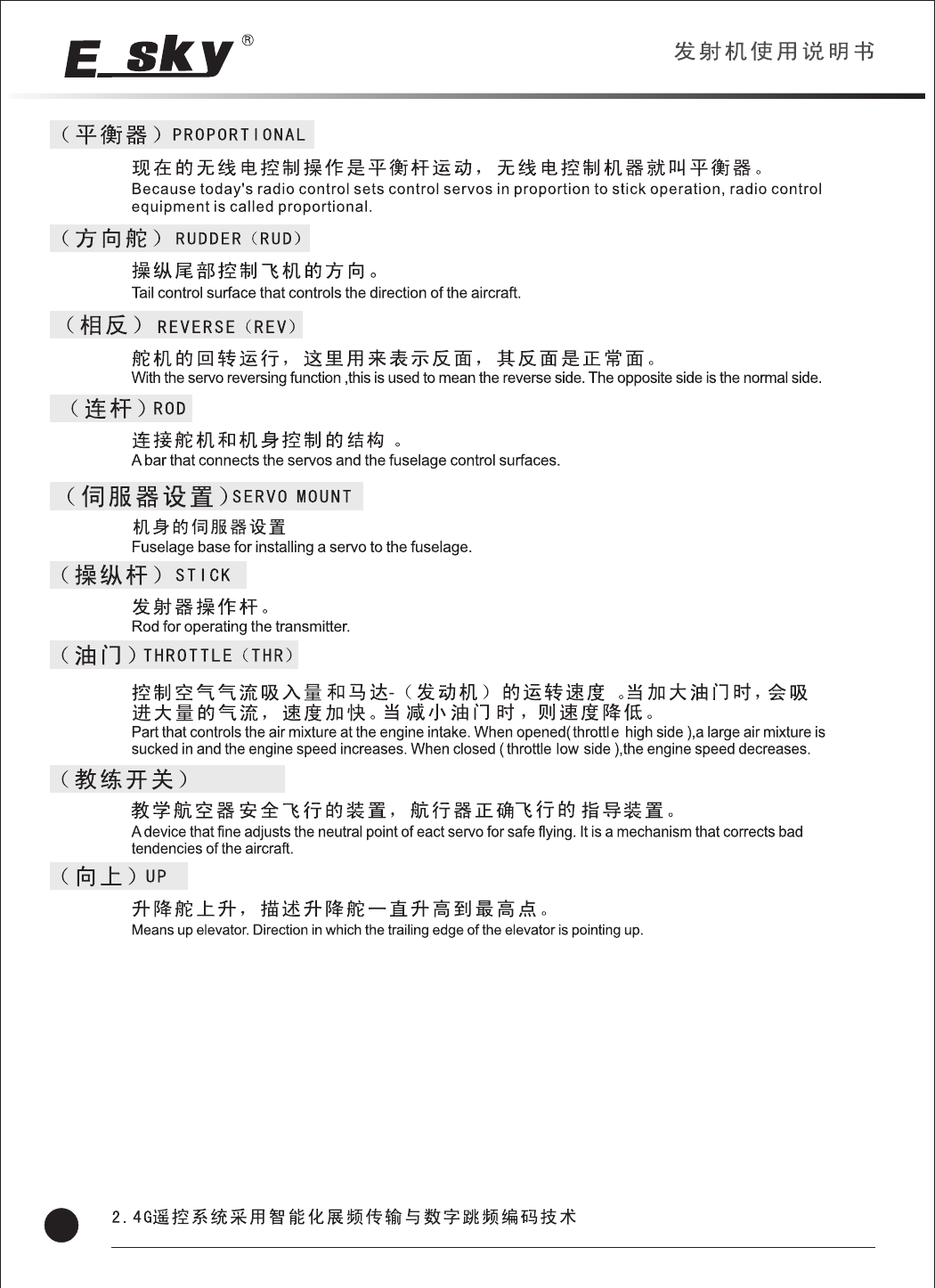
4. At last, check the range curve of each servo direction, turn the servo horn rod outward if the range is
too small and turn it inward while the range is too large.
5. After finishing all the connections, recheck the operating direction and setting etc.
Please charge with an adapter, overcharge or overheating may cause
burn or fire etc. or combustion. Please charge Ni-CD/Ni-MH battery
with original TWF changer or quick charger, and power off the charger
in time after finishing the charging .
2.4G
2.4G TRANSMITTER INSTRUCTION MANUAL
16
2.4G Remote control system adopts Advanced Spread Spectrum Technology and digital FSK (frequency shift key) Coding Technology.

Always be sure that the batteries are loaded in the
correct polarity order. If the batteries are loaded
incorrectly, the transmitter will be unworkable .
Please take the battery out during the suspended
period, please clean it with dry cloth if there is some
liquid leaking out from the battery.
When the green lamp of the battery voltage
indicator(LED) goes off or the Red LED
flashes, please exchange the batteries or
charge them immediately.
+-
LED)
2.4G
2.4G TRANSMITTER INSTRUCTION MANUAL
18
2.4G Remote control system adopts Advanced Spread Spectrum Technology and digital FSK (frequency shift key) Coding Technology.
TRAINER
2.4G
2.4G TRANSMITTER INSTRUCTION MANUAL
19 2.4G Remote control system adopts Advanced Spread Spectrum Technology and digital FSK (frequency shift key) Coding Technology.
The users manual or instruction manual for an intentional or unintentional radiator shall
caution the user that changes or modifications not expressly approved by the party
responsible for compliance could void the user's authority to operate the equipment. In
cases where the manual is provided only in a form other than paper, such as on a
computer disk or over the Internet, the information required by this section may be
included in the manual in that alternative form, provided the user can reasonably be
expected to have the capability to access information in that form.
NOTE: This equipment has been tested and found to comply with the limits for a Class B
digital device, pursuant to Part 15 of the FCC Rules. These limits are designed to provide
reasonable protection against harmful interference in a residential installation. This
equipment generates, uses and can radiate radio frequency energy and, if not installed
and used in accordance with the instructions, may cause harmful interference to radio
communications. However, there is no guarantee that interference will not occur in a
particular installation.
If this equipment does cause harmful interference to radio or television reception, which
can be determined by turning the equipment off and on, the user is encouraged to try to
correct the interference by one or more of the following measures:
-- Reorient or relocate the receiving antenna.
-- Increase the separation between the equipment and receiver.
-- Connect the equipment into an outlet on a circuit different from that to which the
receiver is connected.
-- Consult the dealer or an experienced radio/TV technician for help.