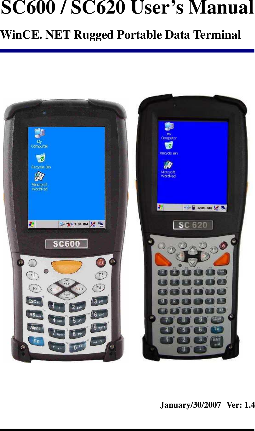
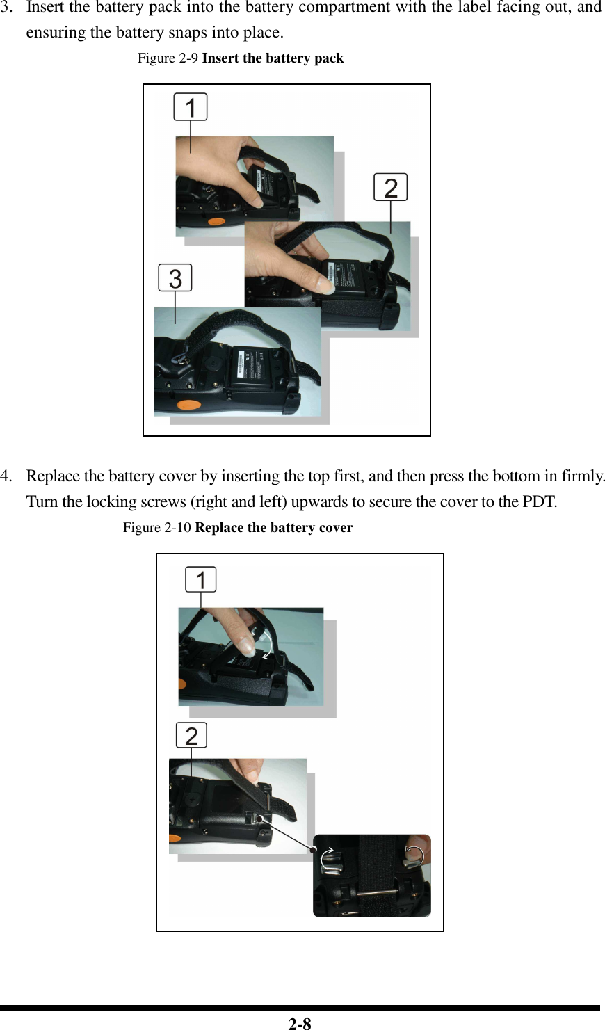
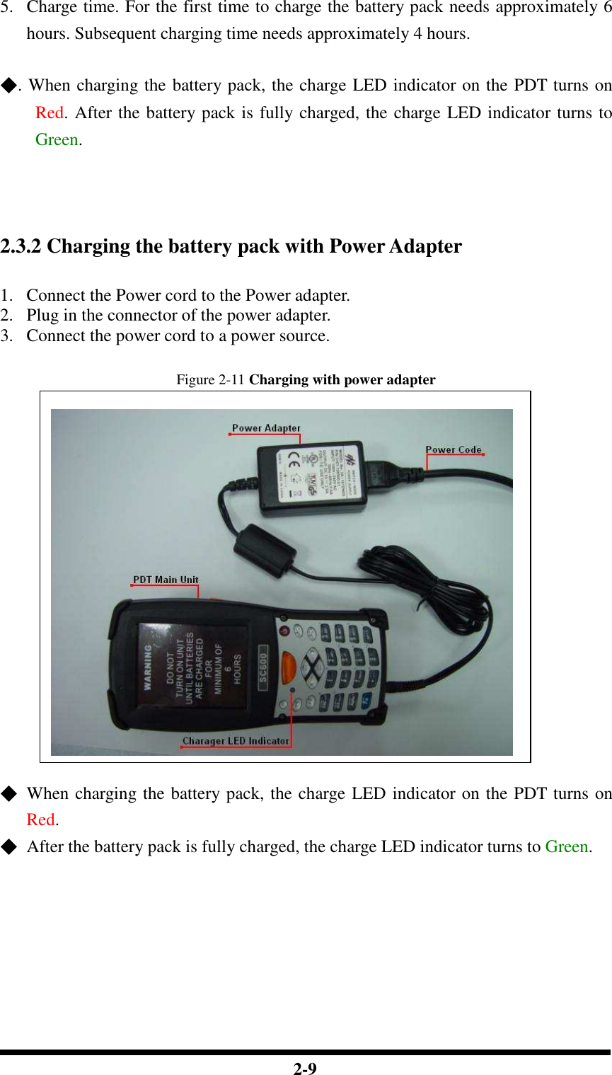
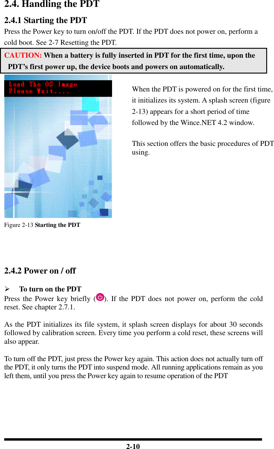
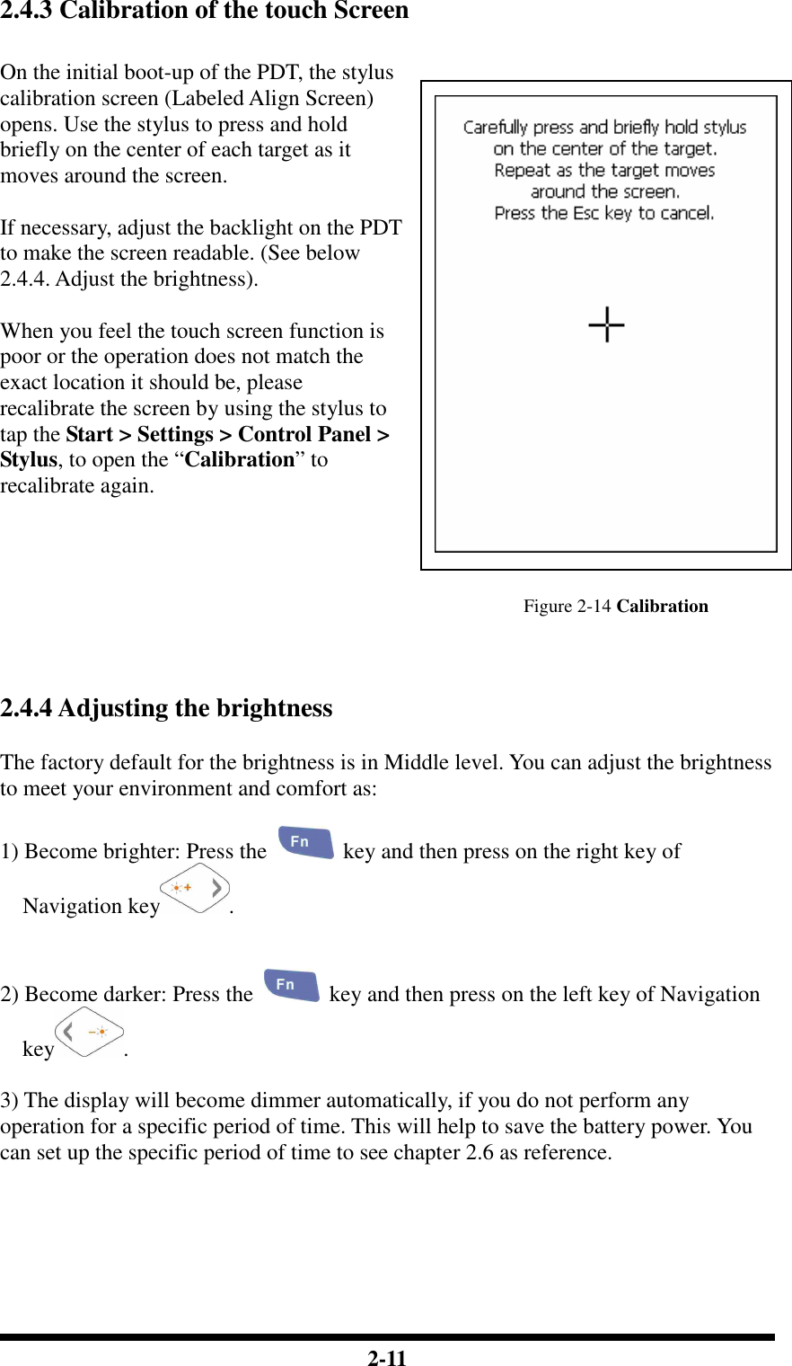
Shin Chuan Computer SC600PDT-BWG Portable Data Terminal User Manual rev4
Shin Chuan Computer Co., Ltd. Portable Data Terminal rev4
Contents
- 1. User manual 1 rev2
- 2. User manual 2 rev2
- 3. Revised manual 1 of 2
- 4. Revised manual 2 of 2
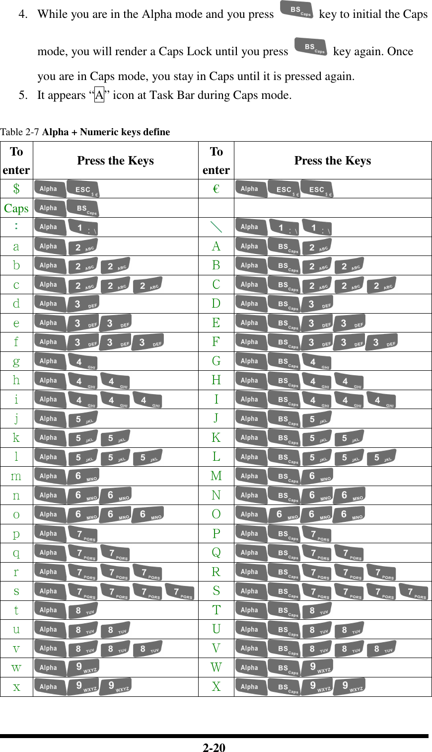
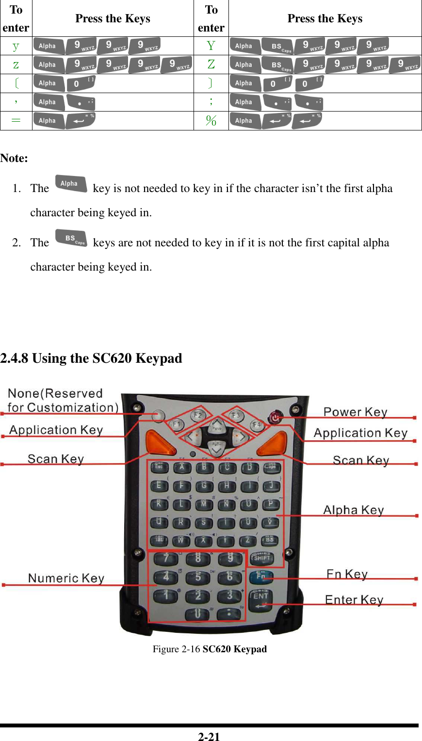
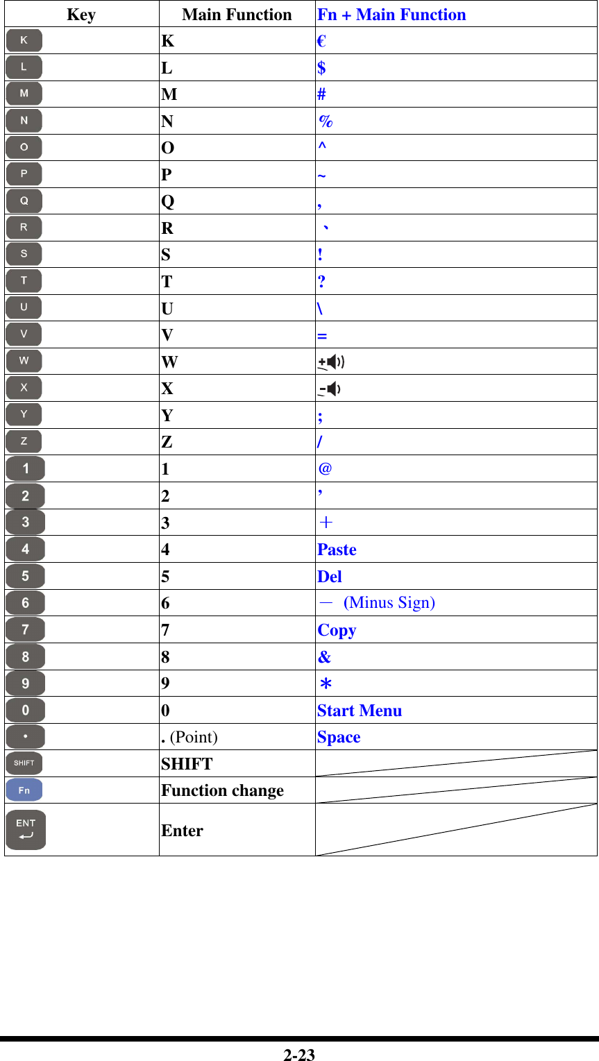
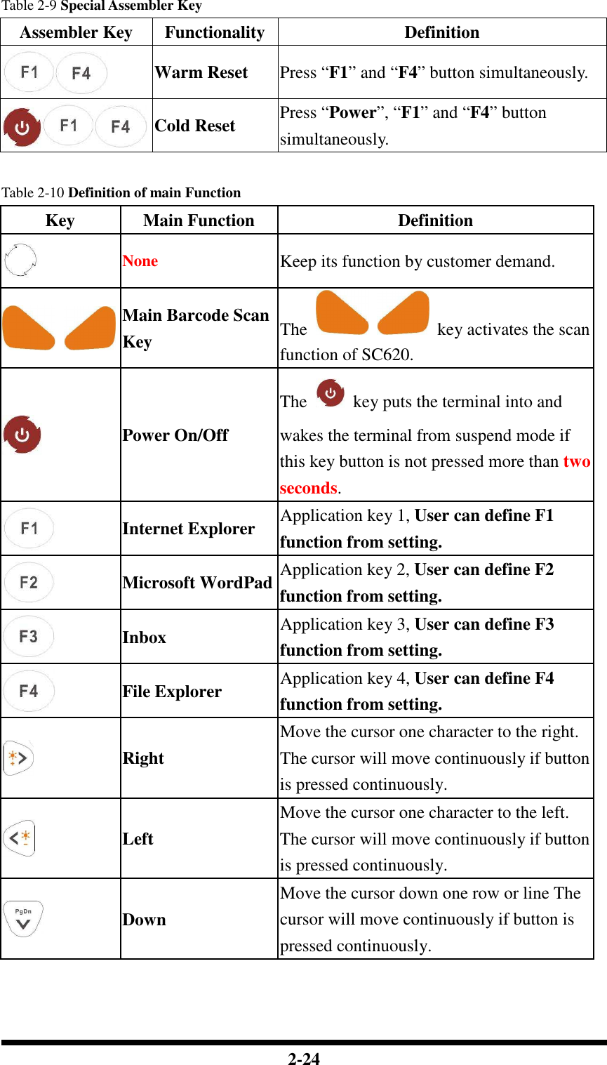
User manual 1 rev2
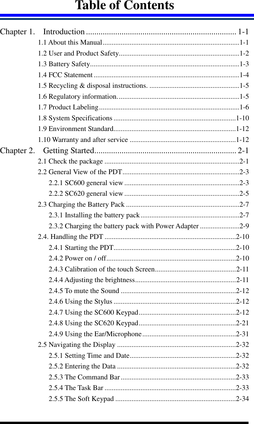


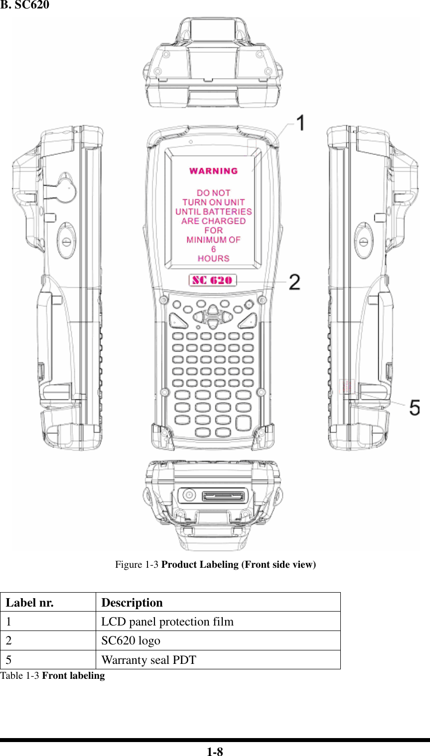
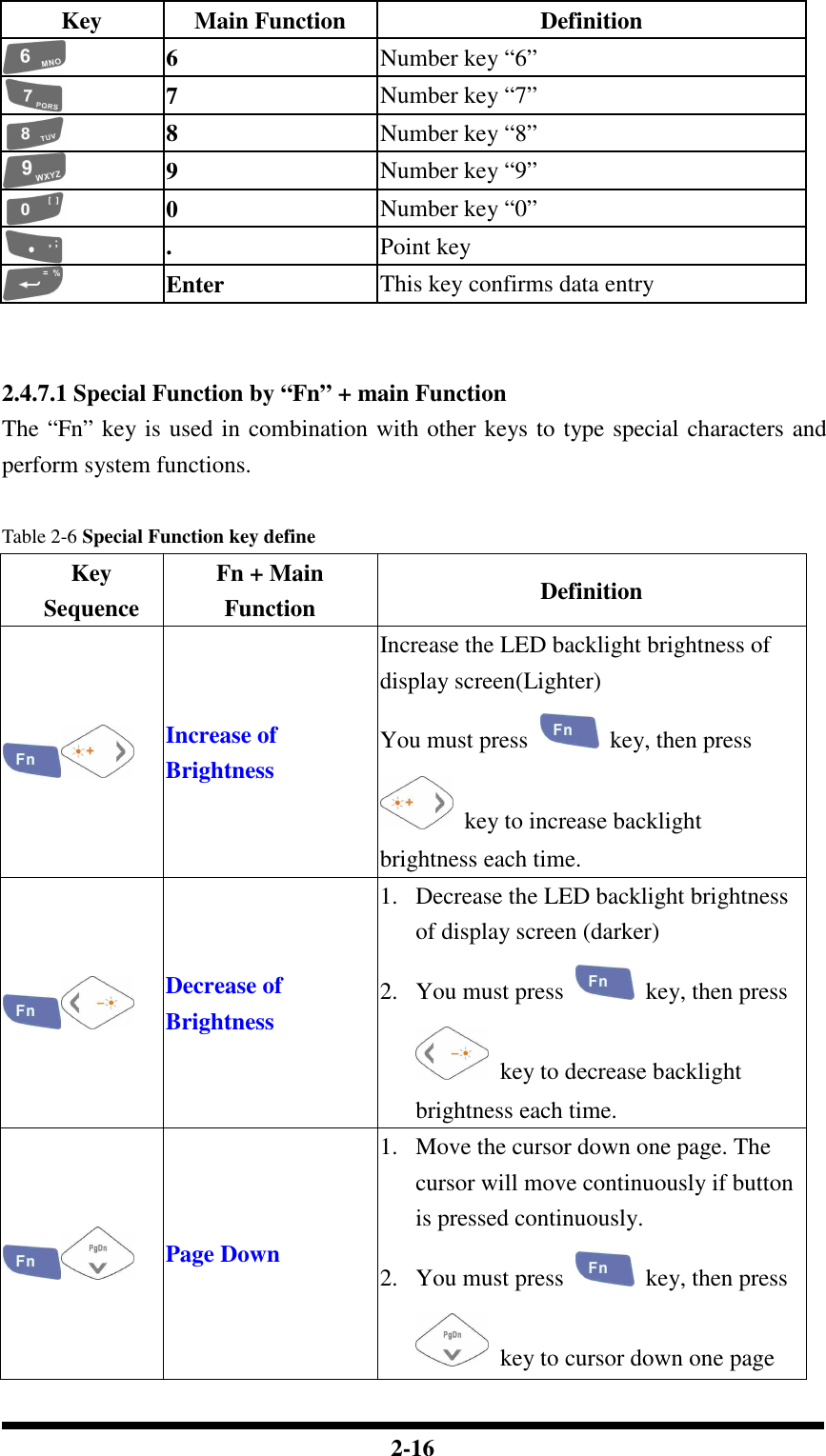
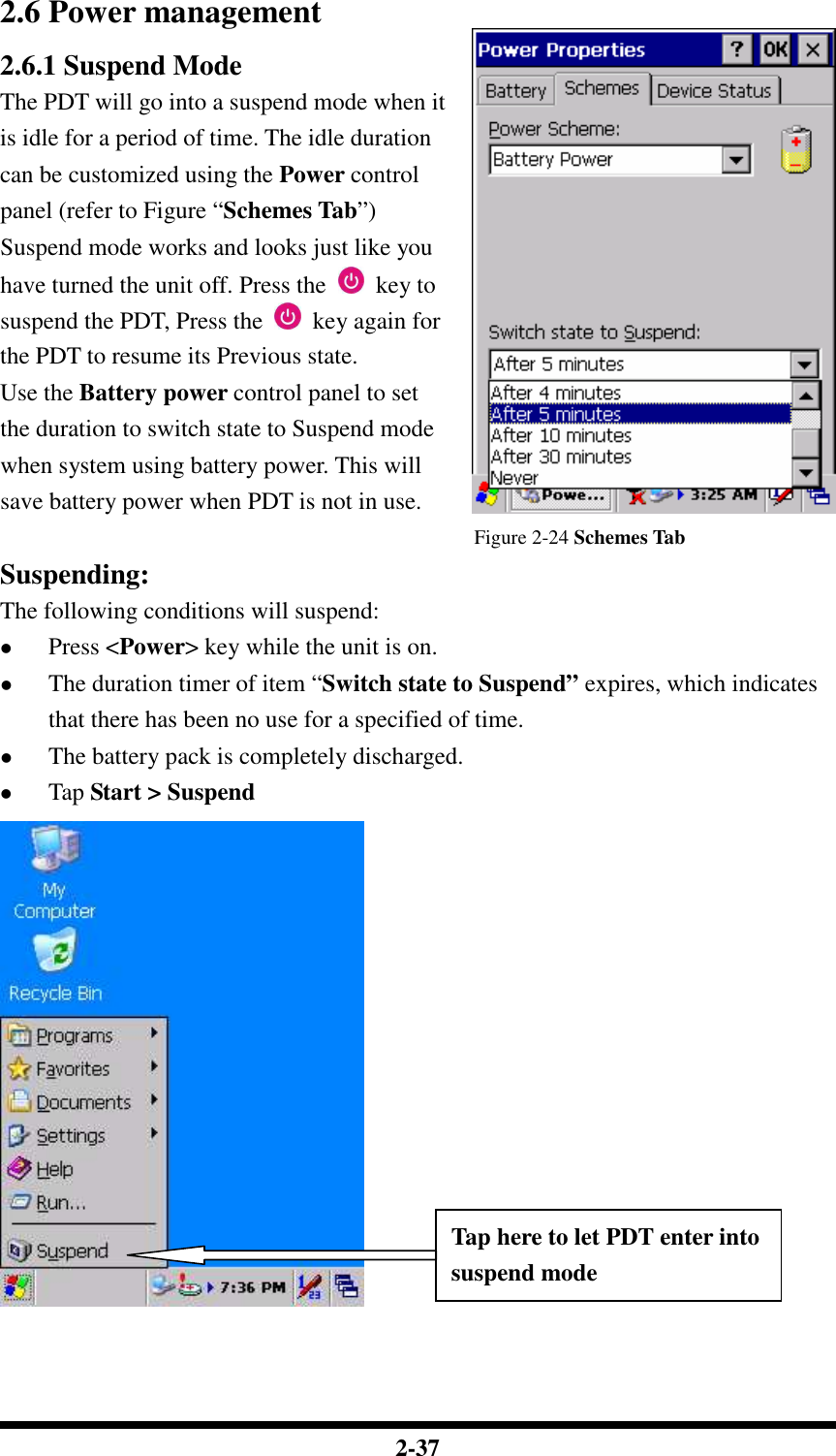
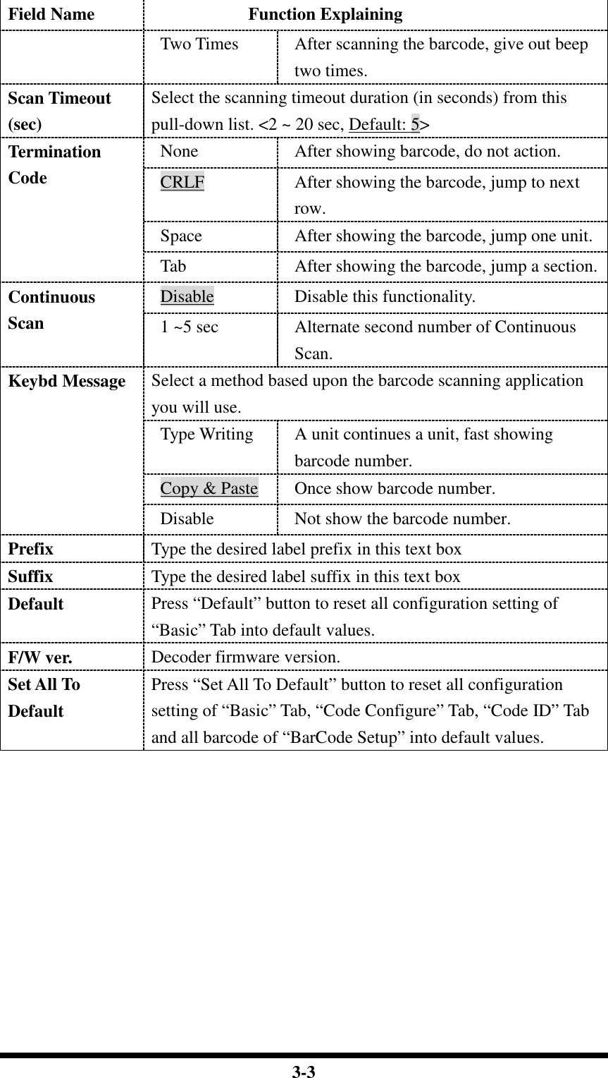
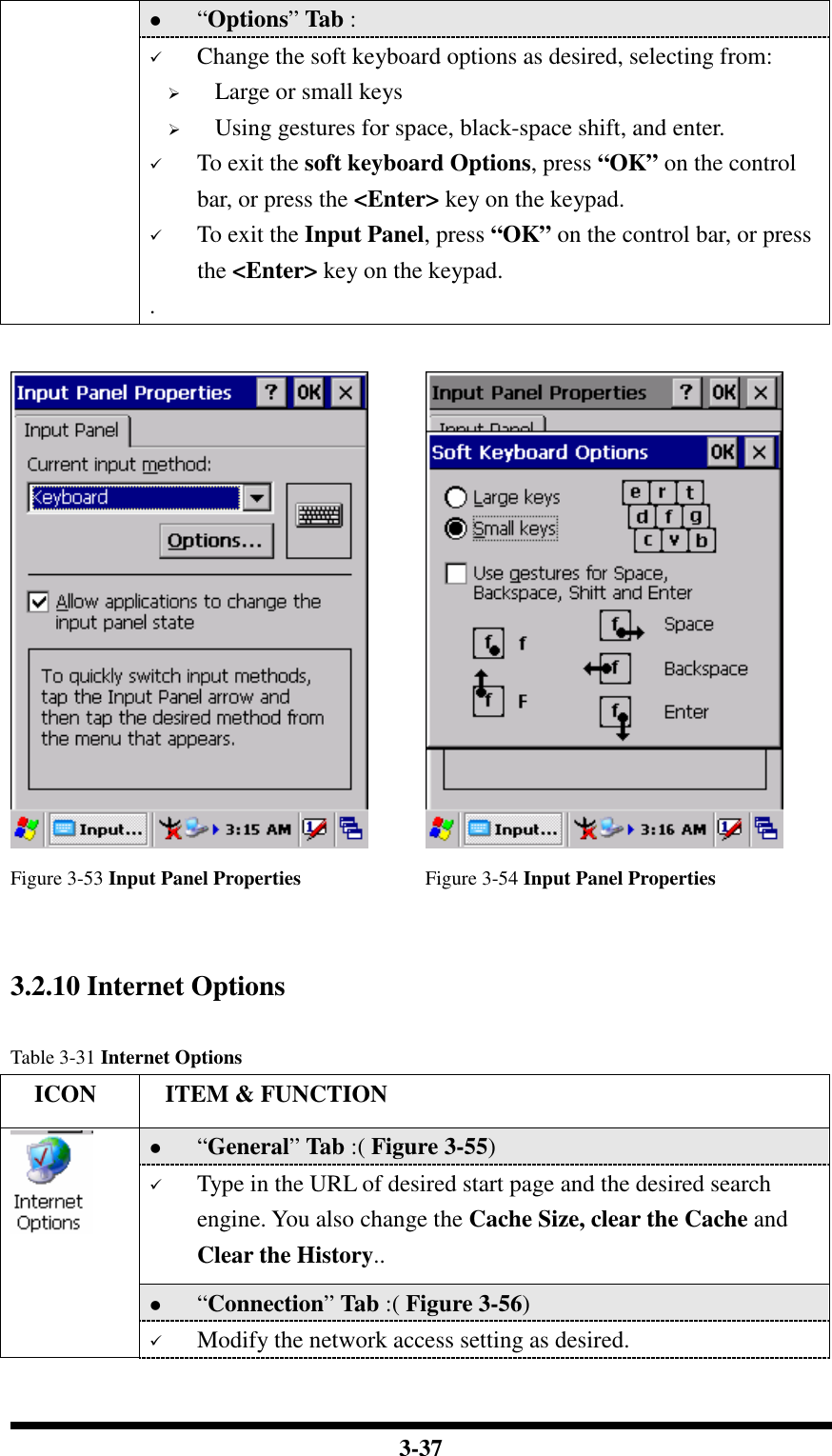
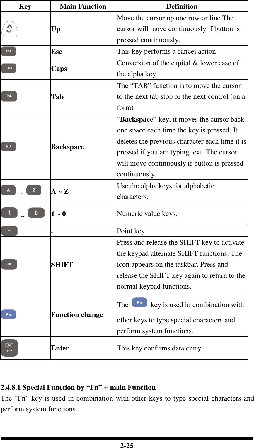
![2-22 Table 2-8 Keypad List Key Main Function Fn + Main Function None Main Barcode Scan Key Power On/Off Internet Explorer Microsoft WordPad Inbox File Explorer Right Increase of Brightness Left Decrease of Brightness Down Page Down Up Page Up Esc Caps Tab Backspace A F5 B F6 C F7 D F8 E ( F ) G [ H ] I { J }](https://usermanual.wiki/Shin-Chuan-Computer/SC600PDT-BWG.User-manual-1-rev2/User-Guide-762143-Page-40.png)
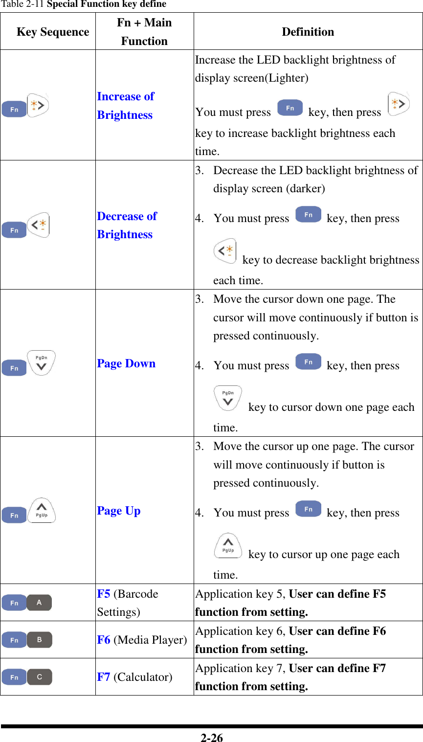
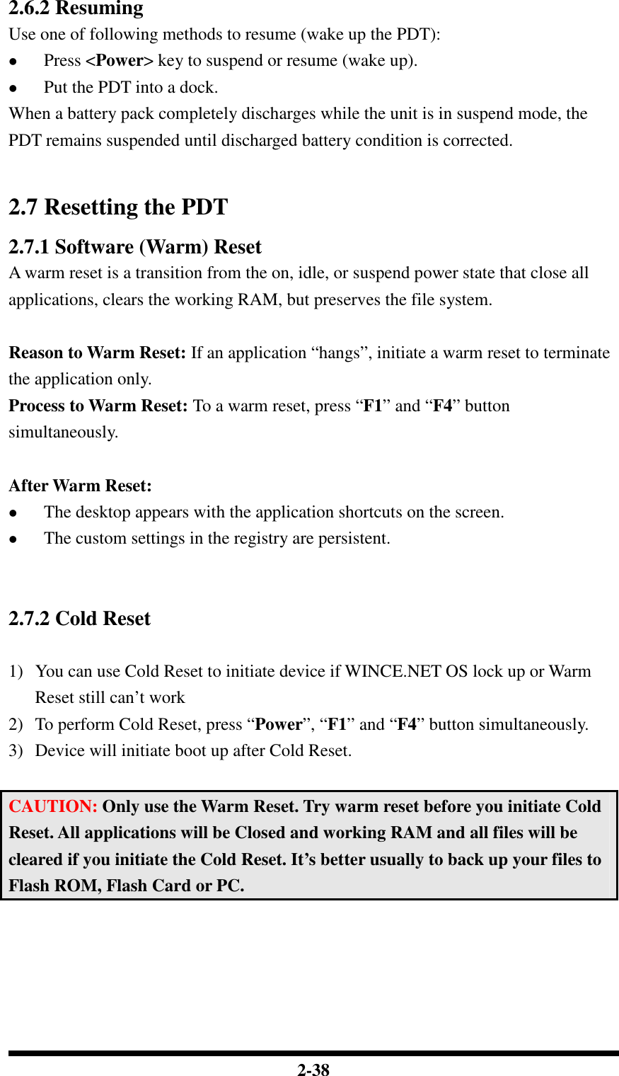
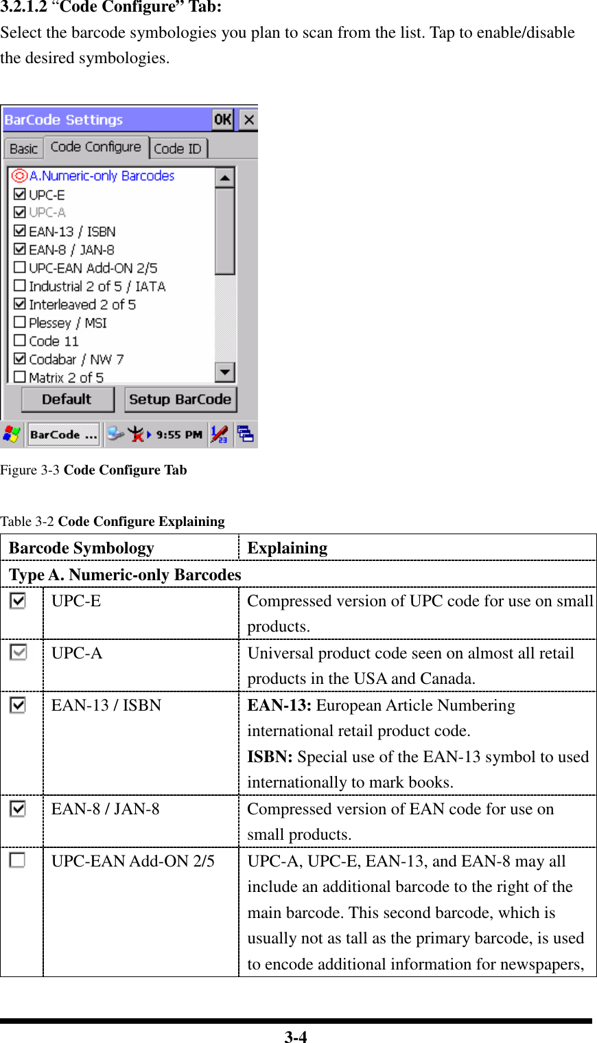
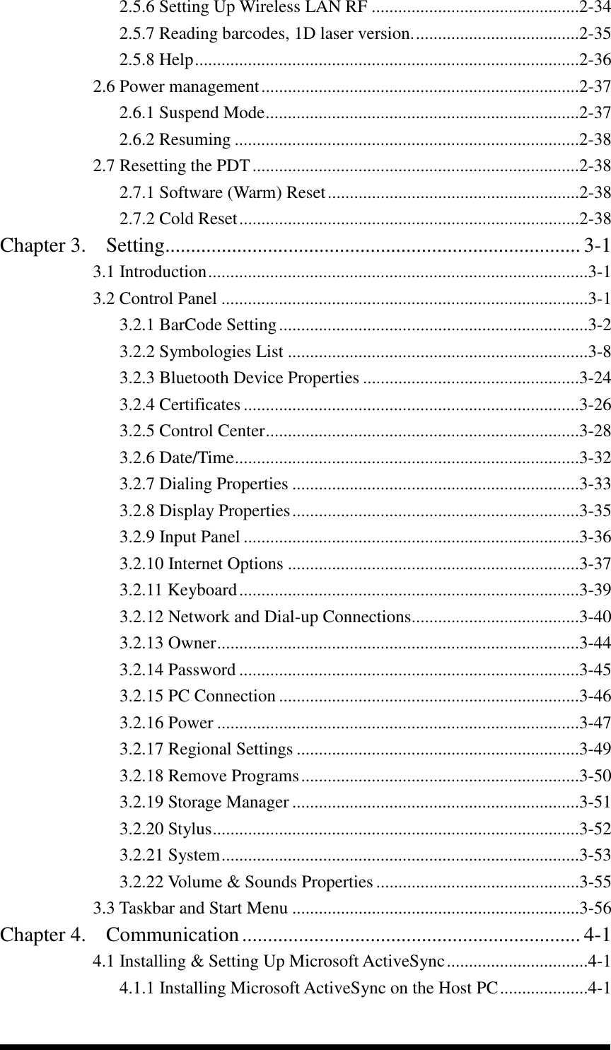
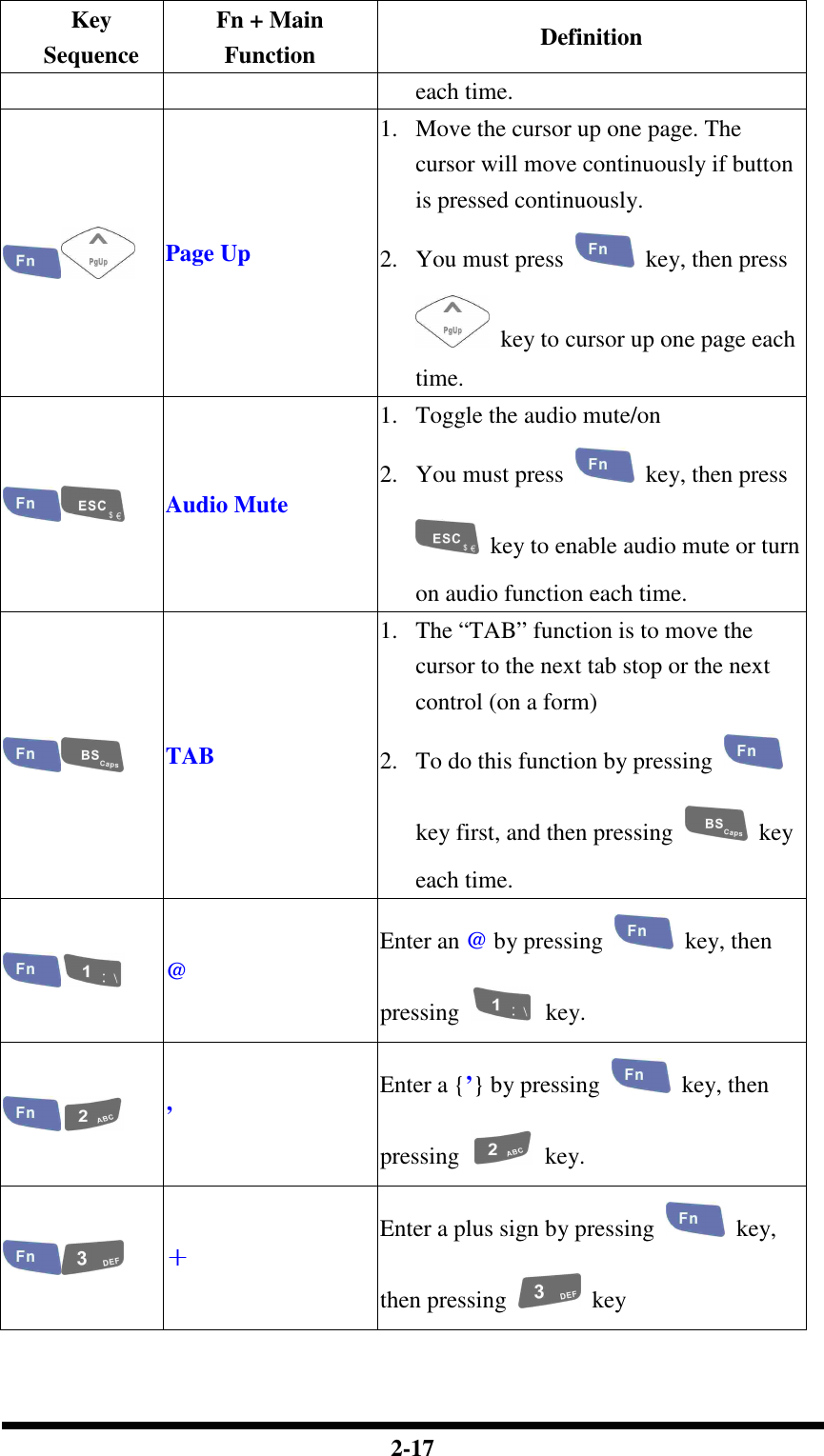
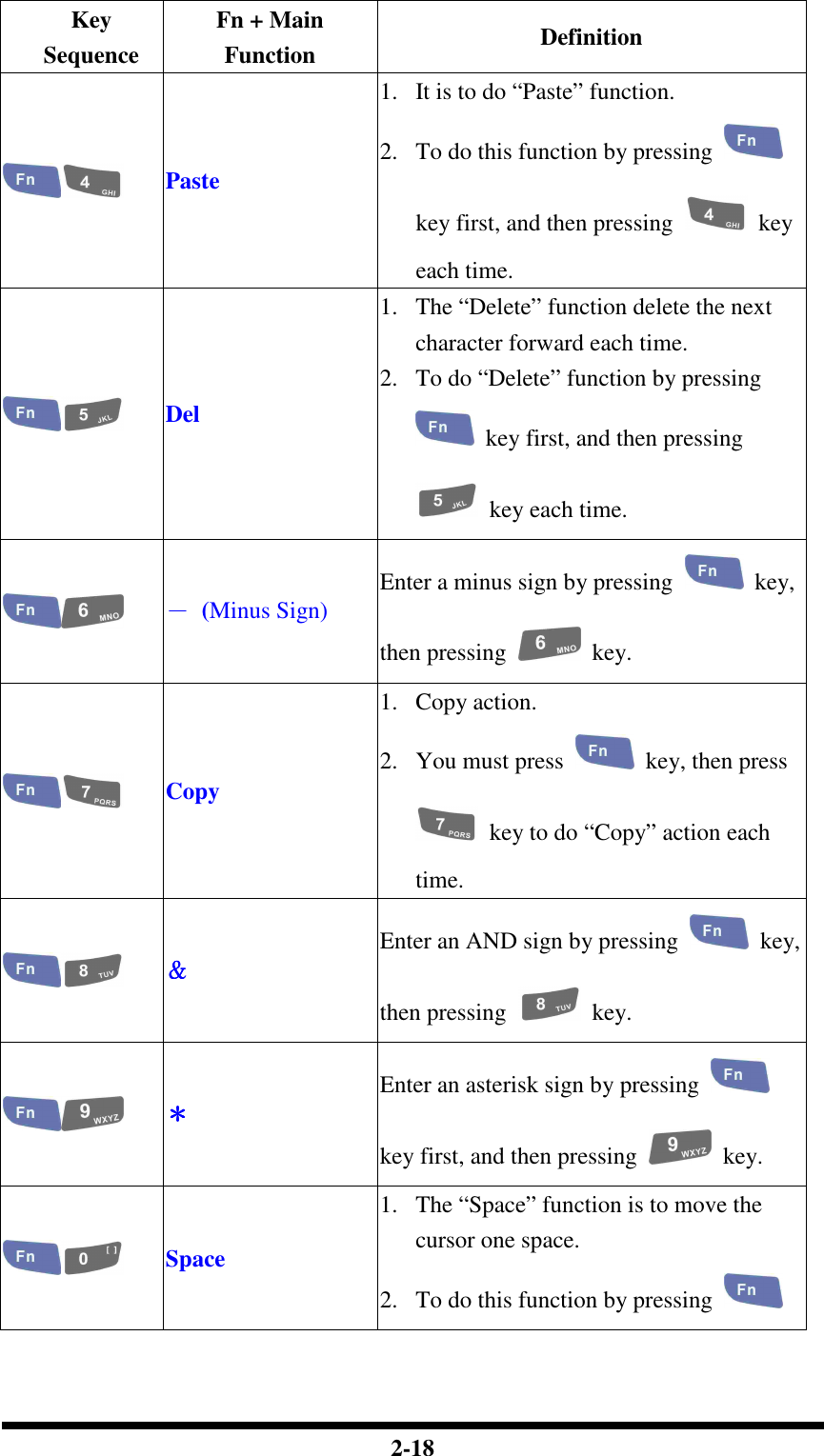
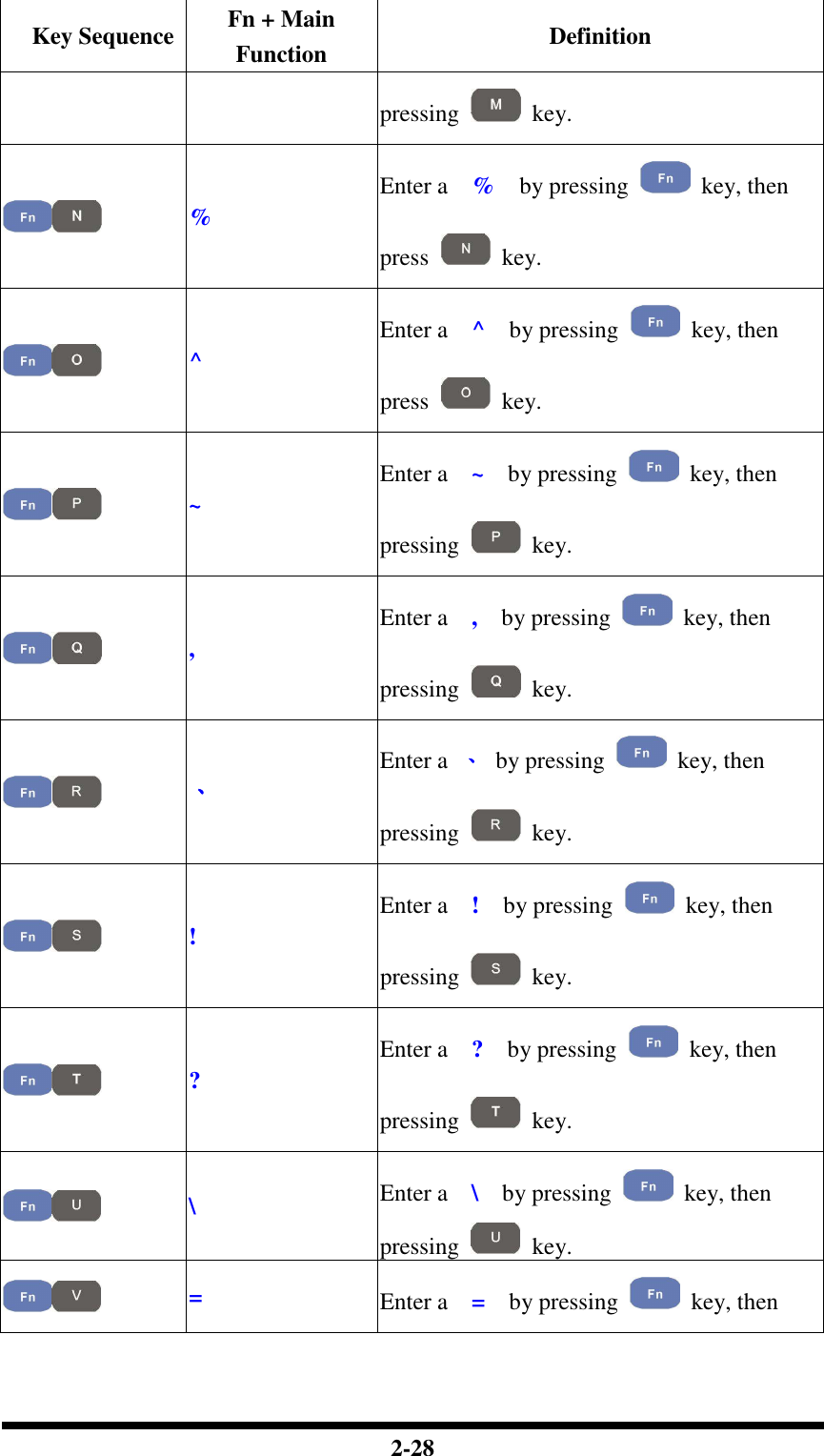
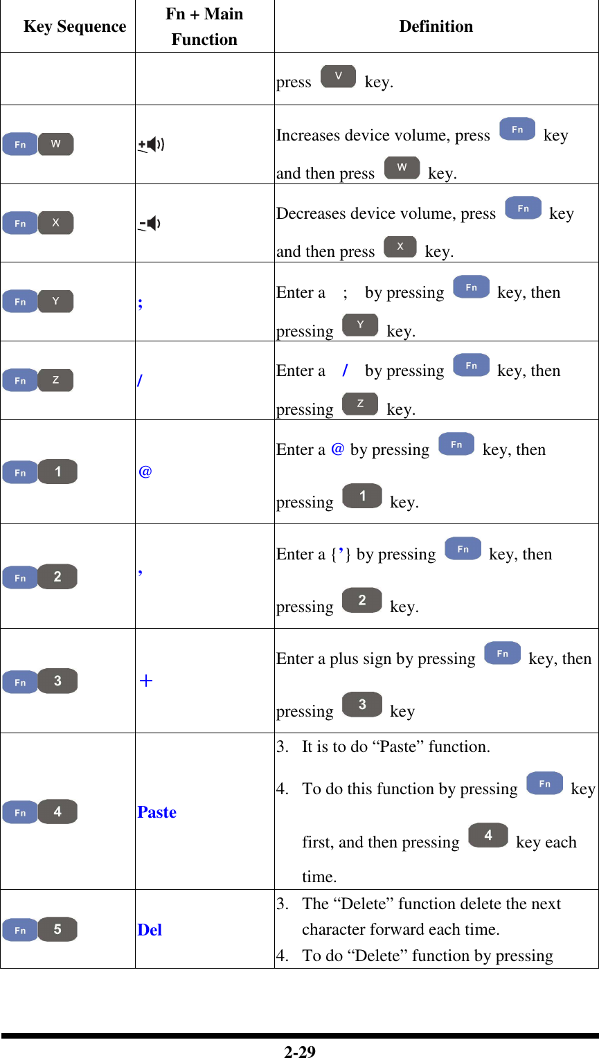
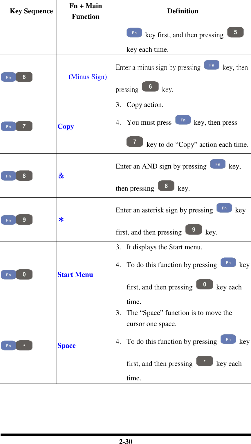
![2-27 Key Sequence Fn + Main Function Definition F8 (Information) Application key 8, User can define F8 function from setting. ( Enter a ( by pressing key, then pressing key. ) Enter a ) by pressing key, then pressing key. [ Enter a [ by pressing key, then pressing key. ] Enter a ] by pressing key, then pressing key. { Enter a { by pressing key, then pressing key. } Enter a } by pressing key, then pressing key. € Enter a € by pressing key, then pressing key. $ Enter a $ by pressing key, then pressing key. # Enter a # by pressing key, then](https://usermanual.wiki/Shin-Chuan-Computer/SC600PDT-BWG.User-manual-1-rev2/User-Guide-762143-Page-45.png)
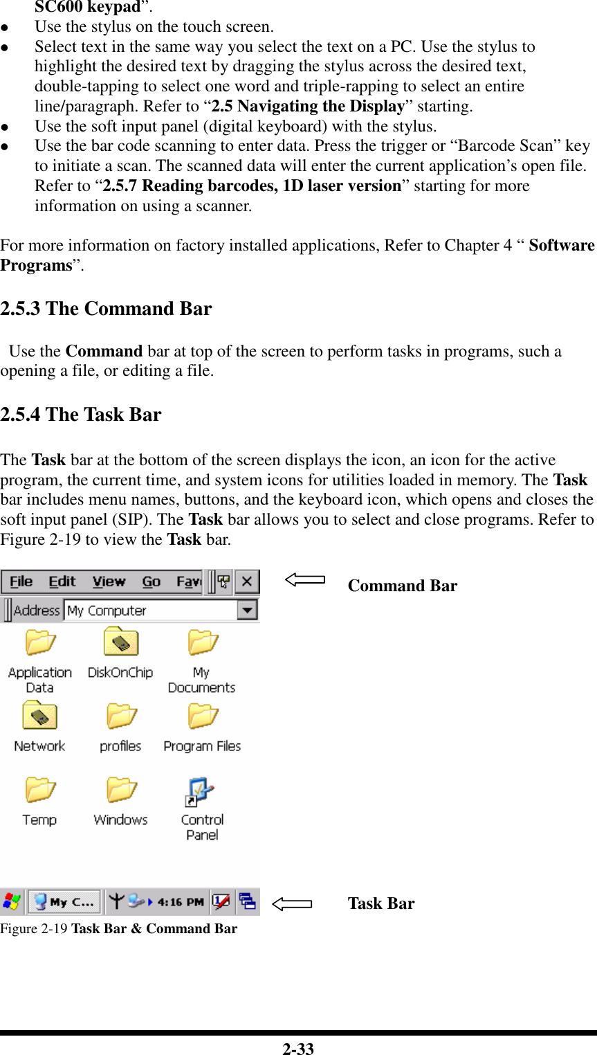
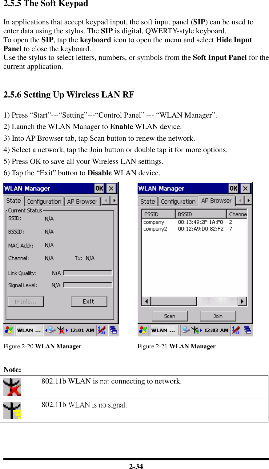
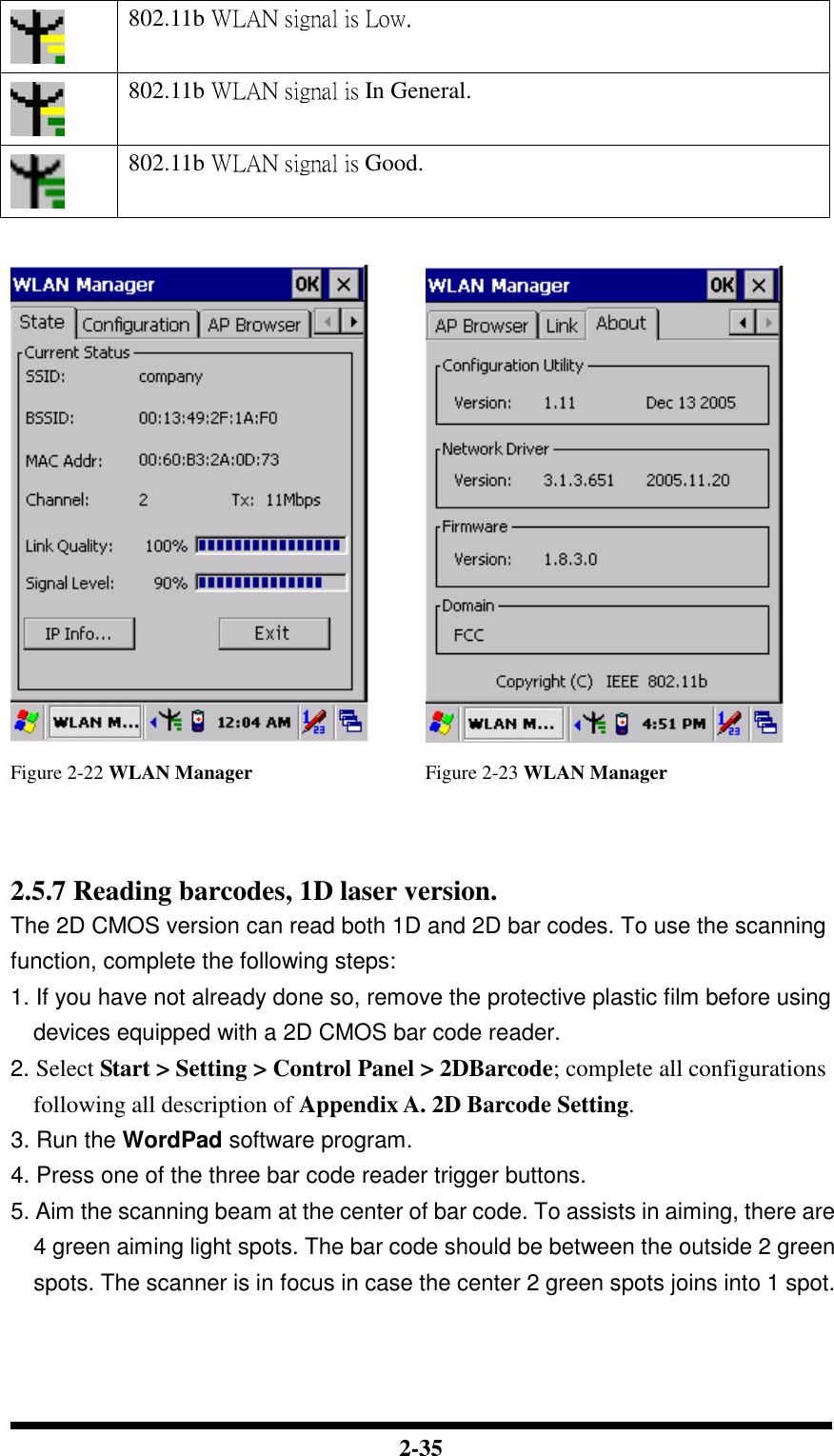
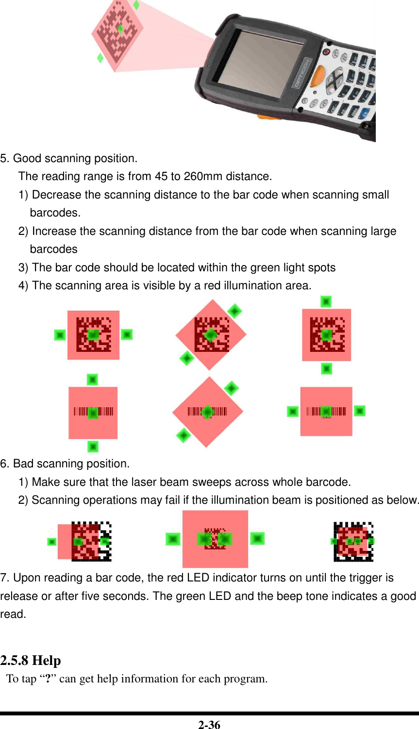
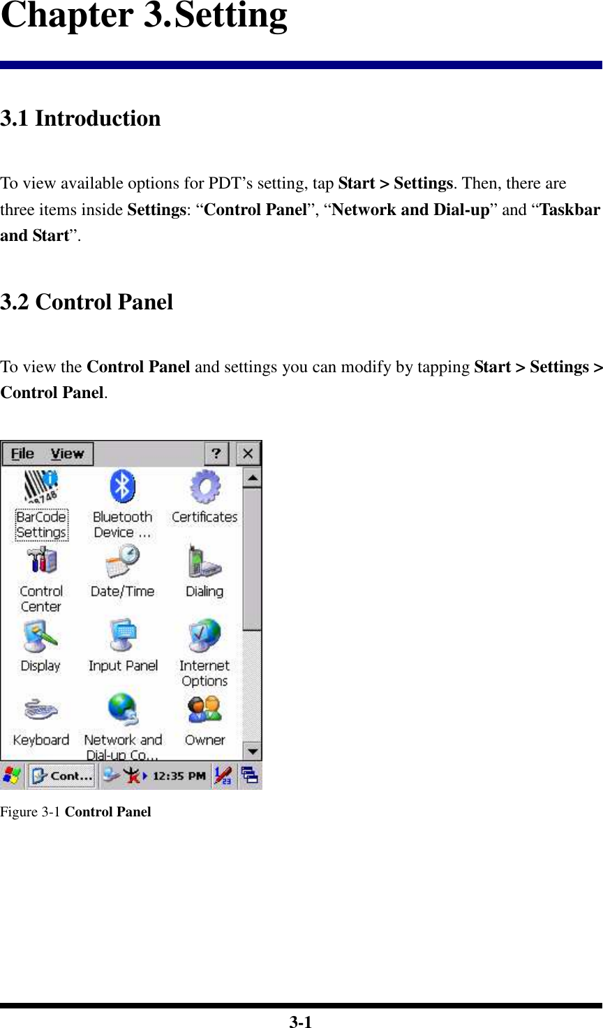
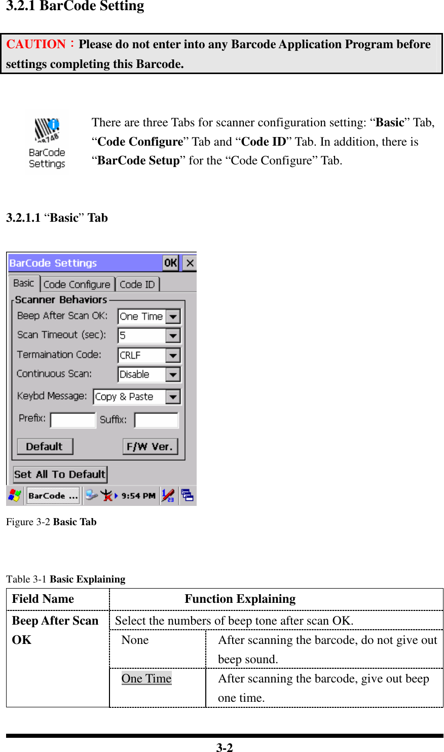
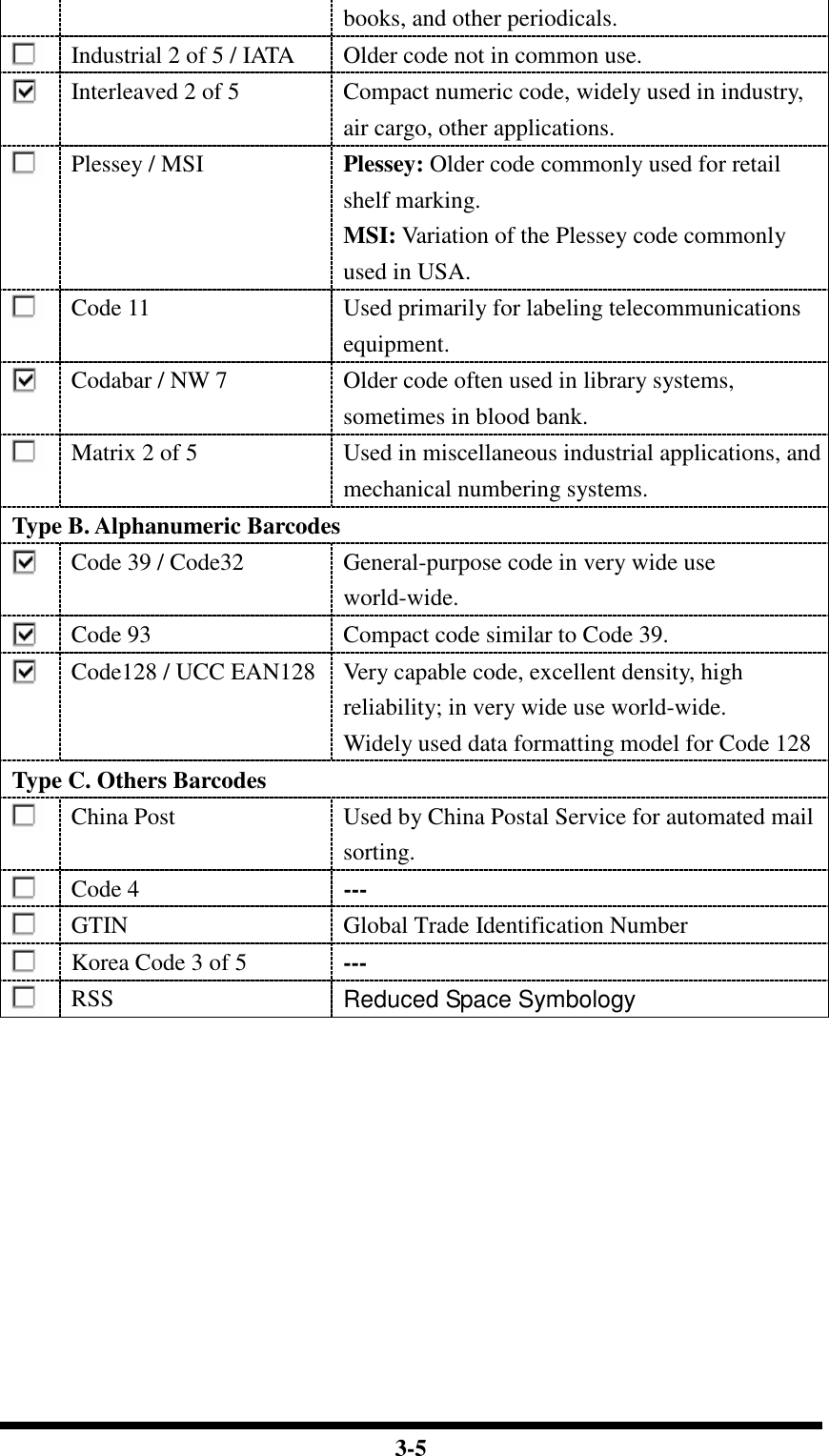
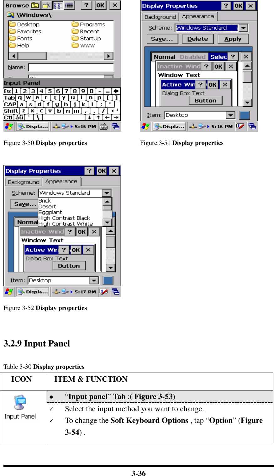
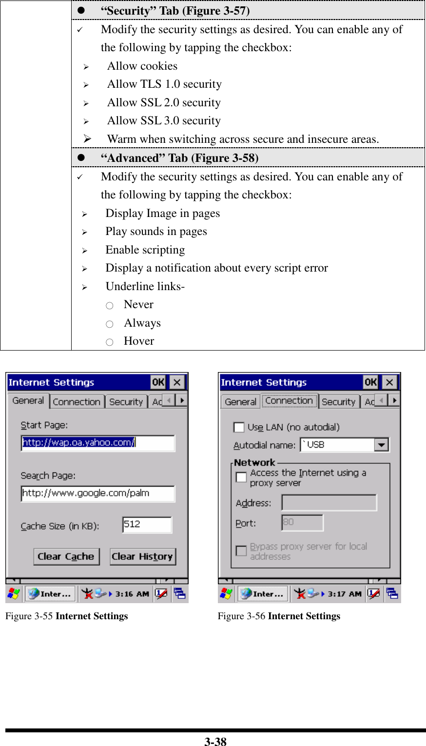
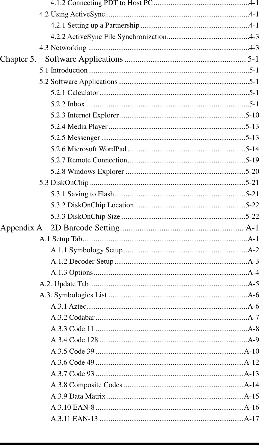
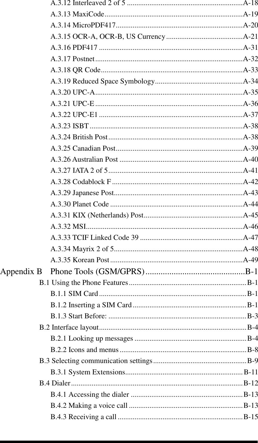
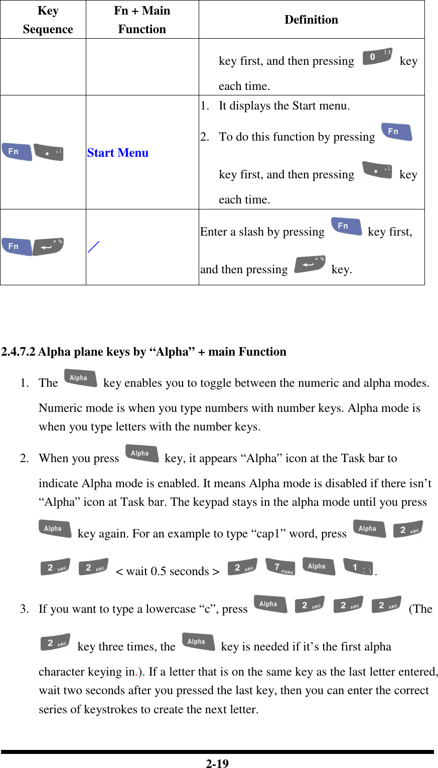
![2-32 2.5 Navigating the Display 2.5.1 Setting Time and Date In the Date/Time options, you can change the year, month, date, time, time zone, or select automatic adjust for Daylight Saving Time. To set or change the date and time: 1. Select Start > Settings > Control Panel > Date/Time 2. To change the year, select the year or open a numeric dial. Select the up arrow to increase the value; select the down arrow to decrease the value. Or you can type a new value in the field. 3. Select the month to open a pull-down list of months or press the arrow buttons to either side of the month to increase or decrease the month. Figure 2-18 Date/Time properties 4. To change the time, select the hour, minute, seconds, or AM/PM and select the up arrow to increase the value; select /tape the down arrow to decrease the value. Or you can type a new value in the field. 5. Select your correct time zone from the pull-down list. 6. To automatically adjust the clock for Daylight Saving Time, enable the checkbox at the bottom of the screen. 7. Select Apply to make save your changes [and make additional modifications] or select OK to exit the Date/Time settings. 2.5.2 Entering the Data To select and open programs, select Start > Programs from the task bar to open a list of available programs. Or if the program has a icon on the desktop, double-tap to open it. There are several ways to enter data on the PDT once in an application: Use the keypad to enter alpha-numeric characters, Refer to “2.4.7 Using the](https://usermanual.wiki/Shin-Chuan-Computer/SC600PDT-BWG.User-manual-1-rev2/User-Guide-762143-Page-50.png)