Shin Chuan Computer SC600PDT-BWG Portable Data Terminal User Manual rev4
Shin Chuan Computer Co., Ltd. Portable Data Terminal rev4
Contents
- 1. User manual 1 rev2
- 2. User manual 2 rev2
- 3. Revised manual 1 of 2
- 4. Revised manual 2 of 2
User manual 1 rev2
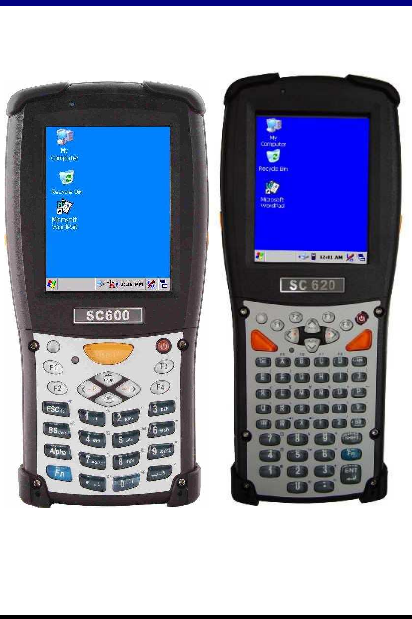
SC600 / SC620 User’s Manual
WinCE. NET Rugged Portable Data Terminal
January/30/2007 Ver: 1.4

Table of Contents
Chapter 1.
Introduction........................................................................ 1-1
1.1 About this Manual............................................................................1-1
1.2 User and Product Safety...................................................................1-2
1.3 Battery Safety...................................................................................1-3
1.4 FCC Statement.................................................................................1-4
1.5 Recycling & disposal instructions. ..................................................1-5
1.6 Regulatory information....................................................................1-5
1.7 Product Labeling..............................................................................1-6
1.8 System Specifications ....................................................................1-10
1.9 Environment Standard....................................................................1-12
1.10 Warranty and after service ...........................................................1-12
Chapter 2.
Getting Started.................................................................... 2-1
2.1 Check the package ...........................................................................2-1
2.2 General View of the PDT.................................................................2-3
2.2.1 SC600 general view ................................................................2-3
2.2.2 SC620 general view ................................................................2-5
2.3 Charging the Battery Pack ...............................................................2-7
2.3.1 Installing the battery pack.......................................................2-7
2.3.2 Charging the battery pack with Power Adapter ......................2-9
2.4. Handling the PDT .........................................................................2-10
2.4.1 Starting the PDT....................................................................2-10
2.4.2 Power on / off........................................................................2-10
2.4.3 Calibration of the touch Screen.............................................2-11
2.4.4 Adjusting the brightness........................................................2-11
2.4.5 To mute the Sound ................................................................2-12
2.4.6 Using the Stylus ....................................................................2-12
2.4.7 Using the SC600 Keypad......................................................2-12
2.4.8 Using the SC620 Keypad......................................................2-21
2.4.9 Using the Ear/Microphone....................................................2-31
2.5 Navigating the Display ..................................................................2-32
2.5.1 Setting Time and Date...........................................................2-32
2.5.2 Entering the Data ..................................................................2-32
2.5.3 The Command Bar................................................................2-33
2.5.4 The Task Bar .........................................................................2-33
2.5.5 The Soft Keypad ...................................................................2-34

2.5.6 Setting Up Wireless LAN RF ...............................................2-34
2.5.7 Reading barcodes, 1D laser version......................................2-35
2.5.8 Help.......................................................................................2-36
2.6 Power management........................................................................2-37
2.6.1 Suspend Mode.......................................................................2-37
2.6.2 Resuming ..............................................................................2-38
2.7 Resetting the PDT..........................................................................2-38
2.7.1 Software (Warm) Reset.........................................................2-38
2.7.2 Cold Reset.............................................................................2-38
Chapter 3.
Setting................................................................................. 3-1
3.1 Introduction......................................................................................3-1
3.2 Control Panel ...................................................................................3-1
3.2.1 BarCode Setting......................................................................3-2
3.2.2 Symbologies List ....................................................................3-8
3.2.3 Bluetooth Device Properties .................................................3-24
3.2.4 Certificates ............................................................................3-26
3.2.5 Control Center.......................................................................3-28
3.2.6 Date/Time..............................................................................3-32
3.2.7 Dialing Properties .................................................................3-33
3.2.8 Display Properties.................................................................3-35
3.2.9 Input Panel ............................................................................3-36
3.2.10 Internet Options ..................................................................3-37
3.2.11 Keyboard.............................................................................3-39
3.2.12 Network and Dial-up Connections......................................3-40
3.2.13 Owner..................................................................................3-44
3.2.14 Password .............................................................................3-45
3.2.15 PC Connection ....................................................................3-46
3.2.16 Power ..................................................................................3-47
3.2.17 Regional Settings ................................................................3-49
3.2.18 Remove Programs...............................................................3-50
3.2.19 Storage Manager .................................................................3-51
3.2.20 Stylus...................................................................................3-52
3.2.21 System.................................................................................3-53
3.2.22 Volume & Sounds Properties ..............................................3-55
3.3 Taskbar and Start Menu .................................................................3-56
Chapter 4.
Communication.................................................................. 4-1
4.1 Installing & Setting Up Microsoft ActiveSync................................4-1
4.1.1 Installing Microsoft ActiveSync on the Host PC....................4-1

4.1.2 Connecting PDT to Host PC ...................................................4-1
4.2 Using ActiveSync.............................................................................4-1
4.2.1 Setting up a Partnership ..........................................................4-1
4.2.2 ActiveSync File Synchronization............................................4-3
4.3 Networking ......................................................................................4-3
Chapter 5.
Software Applications ........................................................ 5-1
5.1 Introduction......................................................................................5-1
5.2 Software Applications......................................................................5-1
5.2.1 Calculator................................................................................5-1
5.2.2 Inbox .......................................................................................5-1
5.2.3 Internet Explorer ...................................................................5-10
5.2.4 Media Player .........................................................................5-13
5.2.5 Messenger .............................................................................5-13
5.2.6 Microsoft WordPad...............................................................5-14
5.2.7 Remote Connection...............................................................5-19
5.2.8 Windows Explorer ................................................................5-20
5.3 DiskOnChip ...................................................................................5-21
5.3.1 Saving to Flash......................................................................5-21
5.3.2 DiskOnChip Location ...........................................................5-22
5.3.3 DiskOnChip Size ..................................................................5-22
Appendix A
2D Barcode Setting......................................................... A-1
A.1 Setup Tab........................................................................................A-1
A.1.1 Symbology Setup ..................................................................A-2
A.1.2 Decoder Setup.......................................................................A-3
A.1.3 Options..................................................................................A-4
A.2. Update Tab ....................................................................................A-5
A.3. Symbologies List...........................................................................A-6
A.3.1 Aztec......................................................................................A-6
A.3.2 Codabar .................................................................................A-7
A.3.3 Code 11 .................................................................................A-8
A.3.4 Code 128 ...............................................................................A-9
A.3.5 Code 39 ...............................................................................A-10
A.3.6 Code 49 ...............................................................................A-12
A.3.7 Code 93 ...............................................................................A-13
A.3.8 Composite Codes ................................................................A-14
A.3.9 Data Matrix .........................................................................A-15
A.3.10 EAN-8 ...............................................................................A-16
A.3.11 EAN-13 .............................................................................A-17

A.3.12 Interleaved 2 of 5 ..............................................................A-18
A.3.13 MaxiCode..........................................................................A-19
A.3.14 MicroPDF417....................................................................A-20
A.3.15 OCR-A, OCR-B, US Currency.........................................A-21
A.3.16 PDF417 .............................................................................A-31
A.3.17 Postnet...............................................................................A-32
A.3.18 QR Code............................................................................A-33
A.3.19 Reduced Space Symbology...............................................A-34
A.3.20 UPC-A...............................................................................A-35
A.3.21 UPC-E ...............................................................................A-36
A.3.22 UPC-E1 .............................................................................A-37
A.3.23 ISBT..................................................................................A-38
A.3.24 British Post........................................................................A-38
A.3.25 Canadian Post....................................................................A-39
A.3.26 Australian Post ..................................................................A-40
A.3.27 IATA 2 of 5........................................................................A-41
A.3.28 Codablock F ......................................................................A-42
A.3.29 Japanese Post.....................................................................A-43
A.3.30 Planet Code .......................................................................A-44
A.3.31 KIX (Netherlands) Post.....................................................A-45
A.3.32 MSI....................................................................................A-46
A.3.33 TCIF Linked Code 39 .......................................................A-47
A.3.34 Mayrix 2 of 5.....................................................................A-48
A.3.35 Korean Post.......................................................................A-49
Appendix B
Phone Tools (GSM/GPRS)..............................................B-1
B.1 Using the Phone Features...............................................................B-1
B.1.1 SIM Card...............................................................................B-1
B.1.2 Inserting a SIM Card.............................................................B-1
B.1.3 Start Before: ..........................................................................B-3
B.2 Interface layout...............................................................................B-4
B.2.1 Looking up messages ............................................................B-4
B.2.2 Icons and menus....................................................................B-8
B.3 Selecting communication settings..................................................B-9
B.3.1 System Extensions...............................................................B-11
B.4 Dialer............................................................................................B-12
B.4.1 Accessing the dialer ............................................................B-13
B.4.2 Making a voice call .............................................................B-13
B.4.3 Receiving a call ...................................................................B-15

B.4.4 Logs.....................................................................................B-16
B.5 Internet connection.......................................................................B-16
B.5.1 Configuration ......................................................................B-16
B.6 SMS..............................................................................................B-17
B.6 Phonebook management ..............................................................B-22
B.7 Internet connections .....................................................................B-24

1-1
Chapter 1. Introduction
Congratulations on purchasing the SC620 Portable Data Terminal (PDT), a Microsoft
Windows®CE .Net rugged PDT. Its special combination of features makes it perfect for
using in a wide range of applications. These features as:
Intel® XScale
TM
PXA255 400MHz 32 bits RISC Processor
Windows® CE .NET 4.2 Operating System
64/128/256 MB SDRAM & 64/128 MB Flash ROM
Open Architecture: User Accessible SD/CF/PCMCIA Slot
240 x 320, 3.5” Color TFT Display with Touch Panel
1 Numeric Keyboards with LED backlight
802.11b Radio Support (Bluetooth Optional)
Optionally Built-in GSM/GPRS Module
Integrated 1D or 2D Barcode Scanner
1.1 About this Manual
The following chapters contained in this manual are:
Chapter 1: Introduction, General information about the PDT.
Chapter 2: Getting started, Describe the basic use of the PDT.
Chapter 3: Setting, Provide basic instructions for customizing
the PDT.
Chapter 4: Communication, Describe how to use all kinds of
communication of the PDT.
Chapter 5: Software Application, Describe the installed applications on the
PDT.
Appendix A. 2D Barcode Setting Provide instructions for customizing the 2D
Engine.
Appendix B Phone Tools
(GSM/GPRS)
Provide instructions for the Phone Tools
Utility

1-2
1.2 User and Product Safety
Do not stare into the laser or LED beam directly or shine it into eyes.
Never use strong pressure onto the screen or subject it to severe impact, as the
LCD panel could become cracked and possibility cause personal injury. If the
LCD panel is broken, never touch the liquid inside because the liquid irritates the
skin.
Although the PDT has passed the test of IP54 standard for water and dust
resistance, avoid prolonged exposure to rain or other concentrated moisture.
Such condition exceeds the IP54 standard, and could result in water or other
contaminants entering into the PDT.
Use only the original approved AC Adapter with the PDT. Use of an unapproved
AC Adapter could result in electrical problems, or even cause a fire or electrical
shock to the user.
Do not disassemble the PDT. Servicing should be done by supplier only. If the
PDT or accessories gets damaged due to wrong handling or unauthorized repair,
warranty is void. In case the warranty seals are broken, warranty is void too.
Make regularly back-ups of all important data.
Under no circumstance will supplier be liable for any direct, indirect,
consequential or incidental damages baring out of the use or inability to use the
hardware and software and/or any data loss, even if supplier has been informed
about the possibility of such damages.

1-3
1.3 Battery Safety
Lithium-ion battery packs might get hot, explode, ignite and/or cause serious injury if
exploded by abusive using. Please follow the safety warnings listed as below:
Do not throw the battery pack in fire. Do not expose the battery to high
temperatures.
Do not connect the positive battery pack with negative battery pack to each other
with any metal object (like wire).
Do not carry or store battery pack together with metal objects.
Do not pierce the battery pack with nails or drills, strike the battery pack with a
hammer, step on the battery pack or otherwise expose it to strong impacts,
shocks or excessive force.
Do not solder onto the battery pack.
Do not expose battery pack to liquid or allow the battery contacts to get wet.
Do not disassemble or modify the battery pack. The battery pack contains safety
and protection measures, which, if damaged, may cause the battery pack to
generate heat, explode or ignite.
Do not discharge the battery pack using any device except for the specified
device. When it is used in devices other than the specified devices, the battery
pack can be damaged or its life expectancy reduced. If the device causes any
abnormal current to flow, it may cause the battery pack to become hot, explode
or ignite and cause serious injury.
In the event the battery pack leaks and the fluid gets into one’s eye, do not rub
the eye. Rinse well with water and immediately seek medical care. If left
untreated, the battery fluid could cause damage to the eye.

1-4
1.4 FCC Statement
Federal Communication Commission Interference Statement
This equipment has been tested and found to comply with the limits for a Class B
digital device, pursuant to Part 15 of the FCC Rules. These limits are designed to
provide reasonable protection against harmful interference in a residential installation.
This equipment generates, uses and can radiate radio frequency energy and, if not
installed and used in accordance with the instructions, may cause harmful interference
to radio communications. However, there is no guarantee that interference will not
occur in a particular installation. If this equipment does cause harmful interference
to radio or television reception, which can be determined by turning the equipment off
and on, the user is encouraged to try to correct the interference by one of the
following measures:
- Reorient or relocate the receiving antenna.
- Increase the separation between the equipment and receiver.
- Connect the equipment into an outlet on a circuit different from that to which the
receiver is connected.
- Consult the dealer or an experienced radio/TV technician for help.
FCC Caution: Any changes or modifications not expressly approved by the party
responsible for compliance could void the user's authority to operate this equipment.
This device complies with Part 15 of the FCC Rules. Operation is subject to the
following two conditions: (1) This device may not cause harmful interference, and (2)
this device must accept any interference received, including interference that may
cause undesired operation.
IMPORTANT NOTE:
Radiation Exposure Statement:
This equipment complies with FCC radiation exposure limits set forth for an
uncontrolled environment. End users must follow the specific operating instructions
for satisfying RF exposure compliance. To maintain compliance with FCC RF
exposure compliance requirements, please follow operation instruction as documented
in this manual.
This transmitter must not be co-located or operating in conjunction with any other
antenna or transmitter.
This phone has been tested and meets the FCC RF exposure requirements when
used with those supplied accessories designed for this product. Third-party
belt-clips, holsters, and similar accessories, if used, should not contain
any metallic components and must keep at least same separation distance from
your body as the original supplied accessory. Body-worn accessories that do

1-5
not meet these requirements may not comply with RF exposure requirements and
should be avoided.
The availability of some specific channels and/or operational frequency bands are
country dependent and are firmware programmed at the factory to match the intended
destination. The firmware setting is not accessible by the end user.
Caution: The FCC ID of SC600 & SC620: TQ2-SC600PDT-BWG
LED AND LASER SAFETY INFORMATION
Class II LED/Laser Product
Do not stare at the LED/Laser or shine into eyes
Do not allow young children to use the product without adult supervision
Do not replace/repair the LED/Laser, these are not user replaceable
Do not shine the LED/Laser on a shiny reflective surface
1.5 Recycling & disposal instructions.
Do not throw this product in the home waste bin. For proper end-of-life
treatment consult the
Environmental care section of www.sccltd.com.tw
1.6 Regulatory information.
For CE, FCC, RoHS and other Document of Conformities, consult the
Regulatory section of www.sccltd.com.tw
1-6
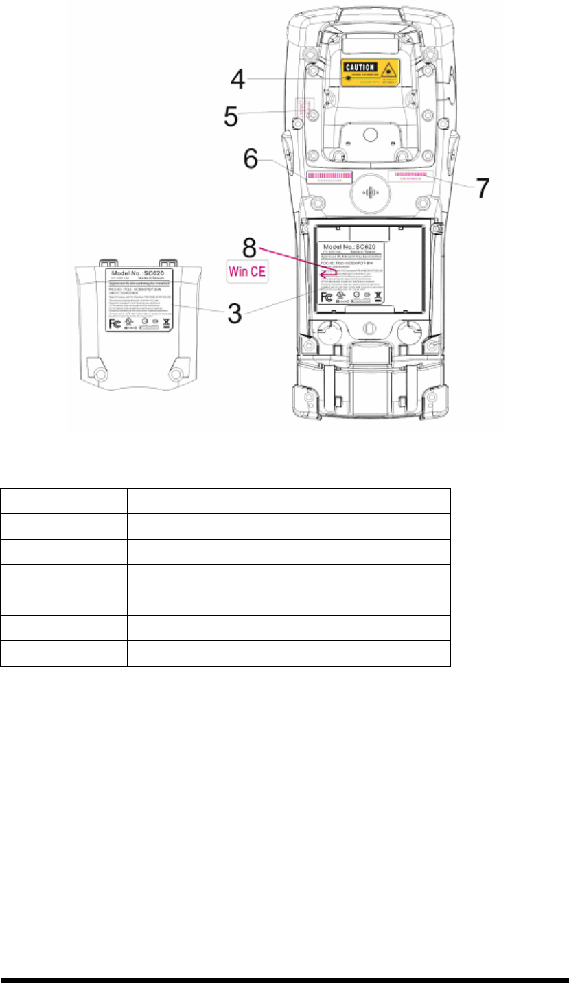
1.7 Product Labeling
The PDT has several labels as showed in Figure 1-1 to 1-4.
A. SC600
Figure 1-1 Product Labeling (Front side view)
Label nr. Description
1 LCD panel protection film
2 SC600 logo
5 Warranty seal PDT
Table 1-1 Front labeling
1-7
Figure 1-2 Product Labeling (Back side view)
Label nr. Description
3 System and regulatory label
4 LED/Laser radiation warning label
5 Warranty label bar code reader
6 Serial number
7 Configuration number
8 Windows CE .NET label
Table 1-2 Rear labeling
1-8
B. SC620
Figure 1-3 Product Labeling (Front side view)
Label nr. Description
1 LCD panel protection film
2 SC620 logo
5 Warranty seal PDT
Table 1-3 Front labeling
1-9
Figure 1-4 Product Labeling (Back side view)
Label nr. Description
3 System and regulatory label
4 LED/Laser radiation warning label
5 Warranty label bar code reader
6 Serial number
7 Configuration number
8 Windows CE .NET label
Table 1-4 Rear labeling

1-10
1.8 System Specifications
The SC600 / SC620 detailed specifications as follows. Unless otherwise noted, all the
specifications are subject to change without prior notification.
Table 1-5 System Specification
SC600 / SC620
Processor
- 400MHz Intel PXA255 32 bits RISC CPU
Memory
- 64 or 128MB Flash ROM
- 64,128 or 256MB SDRAM
Display
- 240 x 320 3.5” TFT 256K Color LCD with LED
backlight
Audio
- One mono speaker
- 2.5mm DIA Stereo Earphone Jack with Microphone
input
Radio Support
- Wireless LAN: 802.11b
- Bluetooth: Class II (optional)
- GSM/GPRS: (optional)
Communication Ports
- USB: Support USB v1.1 both host and client.
- Serial: RS232 via optional cable.
Scan Engine
- Default: Opticon Laser (1D) Engine
- Optional: HHP 2D Imager.
Expansion Slot
- One SD Card Slot
(SD memory only, no SDIO support)
- One Compact Flash type-II Slot
(Availability depends of PDT model)
LED
- One Triple-Color LED for Charger Indicator and
Alarm Notification
- One Dual-Color LED for Scanner Indicator
Power System
- Standard Li-Ion Battery Pack, 3.7V, 3000mAh
- Power Adapter: 100~240V AC, 50/60Hz Input ;
5VDC/2.6A, 3A Output

1-11
SC600 / SC620
SC600
- One Power Button
- Three Barcode Scanner Buttons
- Four Navigation Buttons
- Four Application Buttons
- Sixteen Alpha-Numeric Keypad
- One Pistol Trigger Button
- One Application Hot Key
Keypad / Buttons
SC620
- One Power Button
- Four Barcode Scanner Buttons
- Four Navigation Buttons
- Four Application Buttons
- Forty-four Alpha-Numeric Keypad
- One Pistol Trigger Button
- One Application Hot Key
SC600
- Dimensions:
L : 192.5mm
W: 91.3mm / 78mm
H: 60.6mm / 42.2mm
- Weight: 560g with Standard Battery Pack
500g without Battery Pack
Dimensions and
Weight
SC620
- Dimensions:
L : 220mm
W: 91.3mm / 78mm
H: 60.6mm / 42.2mm
- Weight: 660g with Standard Battery Pack
600g without Battery Pack
Color
- Black
Peripherals and
Accessories
- Optional: RS232 Serial Cable for Terminal / USB
Host Cable for Terminal / High-Capacity Li-Ion
Battery Pack (3.7V, 4000 mAh) / Single Dock / 4
Slot Battery Charger / Car Adapter / Holster / Protect
Film
Software
- Microsoft Windows CE.NET 4.2 Professional

1-12
1.9 Environment Standard
Table 1-6 Environment Standards
Operating Temperature
14
o
F ~ 122
o
F( -10
o
C ~ 50
o
C)
Storage Temperature
-4
o
F ~ 158
o
F (-20
o
C ~ 70
o
C)
Humidity
5% ~ 80% (non-condensing)
Drop
5ft (1.5m) Drop to Concrete
Water & Dust proof
IP54 Certificated & IP64 Compliant
Vibration
MIL STD 810F
1.10 Warranty and after service
Should this PDT be malfunctioned, please contact your original retailer providing
information about the product name, the serial number, and the details about the
problem.
2-1
Chapter 2. Getting Started
2.1 Check the package
Open the package and check all the parts are inside without shortage and damage:
A. SC600
Figure 2-1 Inside the package
1. SC600 Terminal
2. Stylus
3. USB Client Cable for Terminal
4. Earphone/ Microphone Set
5. Standard AC Adapter 5VDC/2.6A
6. AC Power Cord
7. Standard Battery Pack (3.7V, 3000 mAh)
8. Quick Guide (not shown in the picture)
2-2
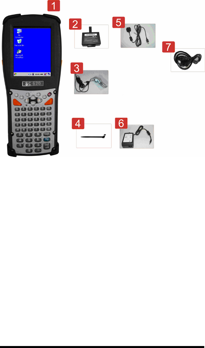
B. SC620
Figure 2-2 Inside the package
1. SC620 Terminal
2. Standard Battery Pack (3.7V, 3000 mAh)
3. Earphone/ Microphone Set
4. Stylus
5. USB Client Cable for Terminal
6. Standard AC Adapter 5VDC/2.6A
7. AC Power Cord
8. Quick Guide (not shown in the picture)
2-3
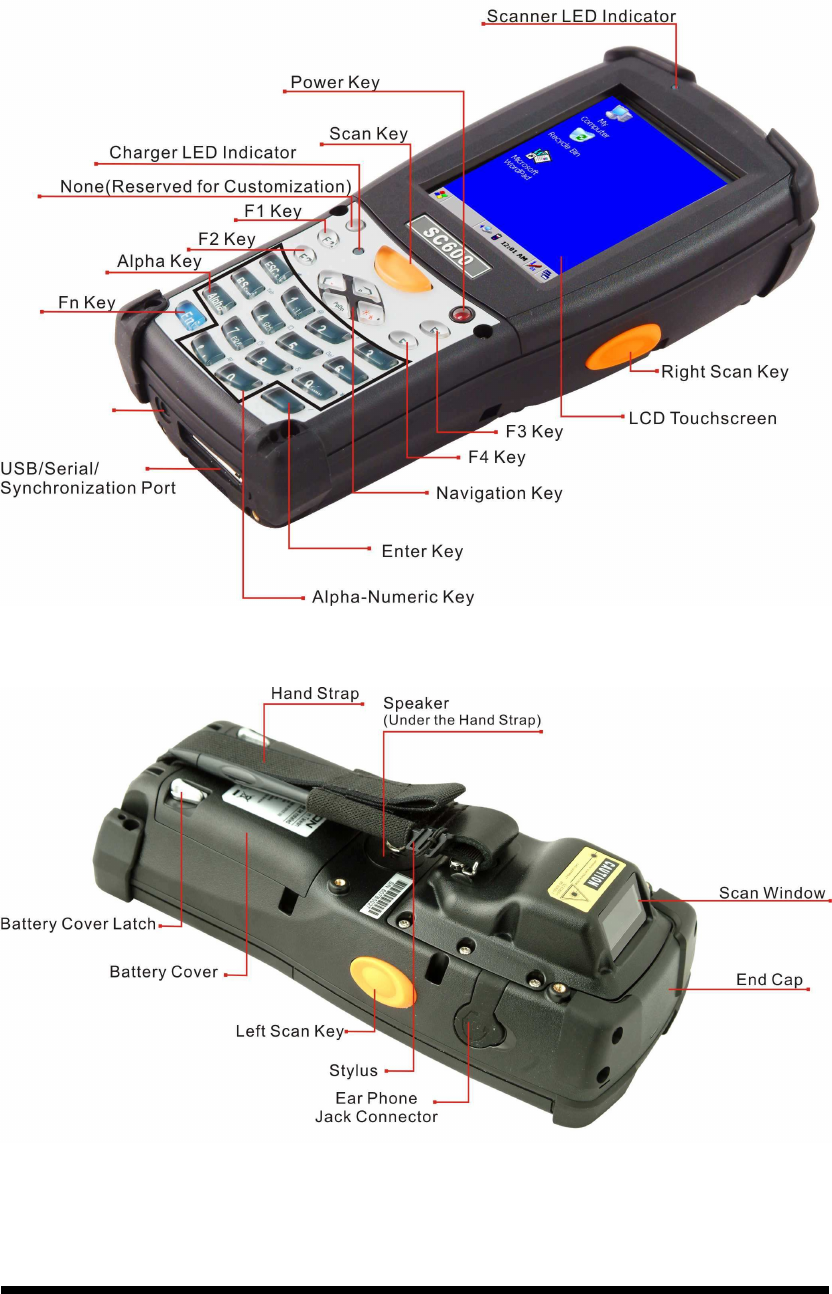
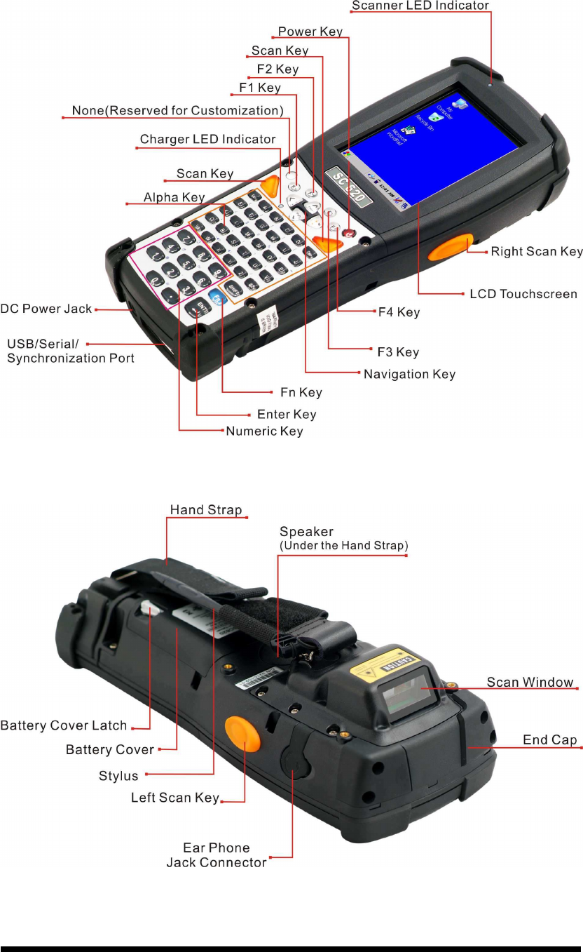
2.2 General View of the PDT
2.2.1 SC600 general view
Figure 2-3 SC600 front side view
Figure 2-4 SC600 back side view

2-4
Table 2-1 Description of SC600 General View
“Red” color Reading barcode 1 Scanner LED Indicator
“Green” color Successful reading
“Red” color Charging battery 2 Charge LED Indicator
“Green” color Battery charged full
3 LCM / Touch Panel Do specific action through touch panel by stylus
4 Left Scan key
Right Scan key
Scan key
Start scanning the barcode by pressing any one of
these three scan keys
5 Power key Puts the terminal into and wakes the terminal from
suspend mode.
6 F1 ~ F4 key The four application keys, hot keys of application
program defined by end user.
7 Navigation key Navigation keys for left, right, up and down
directions
8 Alpha-Numeric keys Numeric keys, Change to Alpha keys after pressing
Alpha key.
9 Alpha key Toggle Alpha-mode for Alpha-Numeric keys
10 Fn key This key is used in combination with other keys to
type special characters and perform system functions.
11 Enter key This key confirms data entry
12 Earphone Jack
Connector
A connector to plug a earphone
13 USB / Serial /
Synchronization port
A connector to support USB Host/Client and serial
functions
14 Scan window A window for scanning of barcode reader
15 Stylus Use the stylus for selecting items and entering
information.
16 Battery Cover Protect Battery pack, keep the switch of battery cover
to leave system from suspend mode
17 Battery cover Latch To keep Battery Cover locked
18 Hand Strap This strap can be sealed tighter or looser
19 Speaker 1.5W speaker for audio sound
20 DC Power Jack A connector to support AC power.
21 End Cap Protect CF slot and SD slot from dust and water
2-5
2.2.2 SC620 general view
Figure 2-5 SC6200 front side view
Figure 2-6 SC620 back side view

2-6
Table 2-2 Description of SC620 General View
“Red” color Reading barcode 1 Scanner LED Indicator
“Green” color Successful reading
“Red” color Charging battery 2 Charge LED Indicator
“Green” color Battery charged full
3 LCM / Touch Panel Do specific action through touch panel by stylus
4 Left Scan key
Right Scan key
Scan key
Start scanning the barcode by pressing any one of
these three scan keys
5 Power key Puts the terminal into and wakes the terminal from
suspend mode.
6 F1 ~ F4 key The four application keys, hot keys of application
program defined by end user.
7 Navigation key Navigation keys for left, right, up and down
directions
8 Alpha keys Numeric keys.
9 Numeric keys Alpha key.
10 Fn key This key is used in combination with other keys to
type special characters and perform system functions.
11 Enter key This key confirms data entry
12 Earphone Jack
Connector
A connector to plug a earphone
13 USB / Serial /
Synchronization port
A connector to support USB Host/Client and serial
functions
14 Scan window A window for scanning of barcode reader
15 Stylus Use the stylus for selecting items and entering
information.
16 Battery Cover Protect Battery pack, keep the switch of battery cover
to leave system from suspend mode
17 Battery cover Latch To keep Battery Cover locked
18 Hand Strap This strap can be sealed tighter or looser
19 Speaker 1.5W speaker for audio sound
20 DC Power Jack A connector to support AC power.
21 End Cap Protect CF slot and SD slot from dust and water
2-7
2.3 Charging the Battery Pack
Before using the PDT, perform the basic procedure of charging the battery pack
through the following steps.
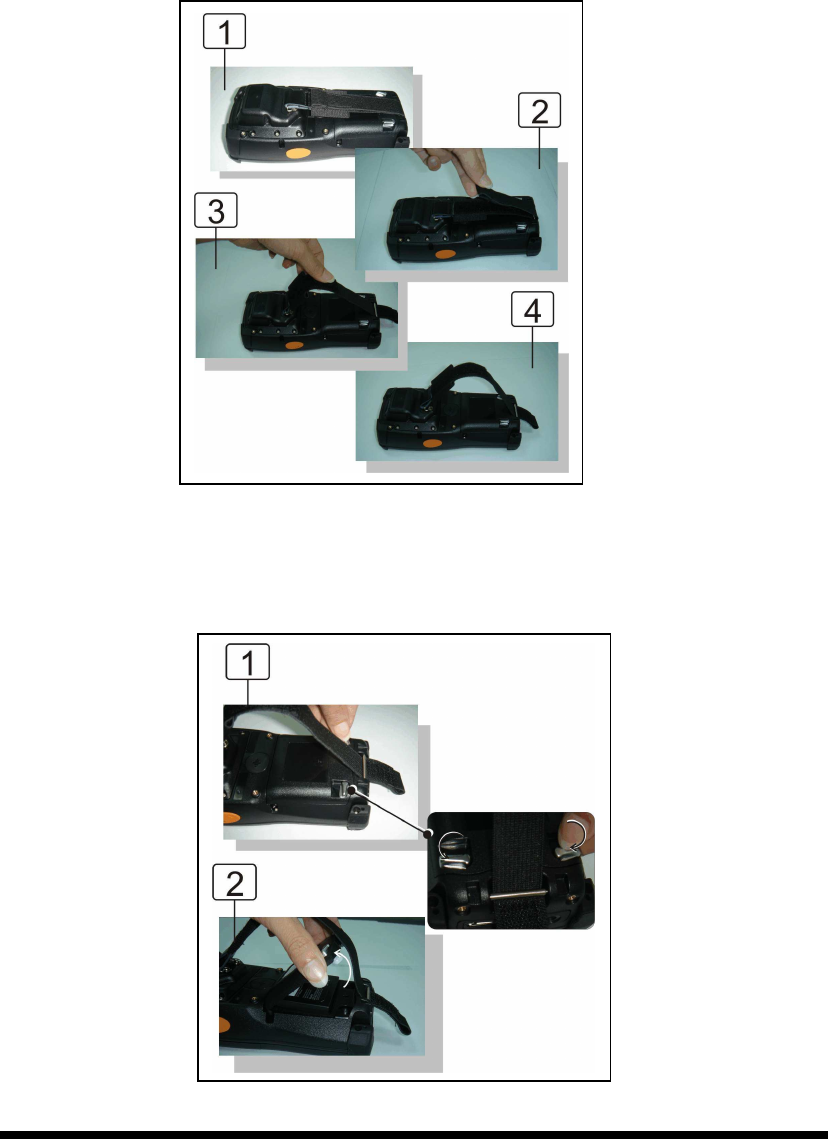
2.3.1 Installing the battery pack
1. On the PDT attached with a hand-strap, detach and loose the hand-strap.
Figure 2-7 Release the Hand strap from PDT
2. Turn the locking screws (right and left) downwards and lift the battery cover away
from the PDT.
Figure 2-8 Detach the battery cover from PDT
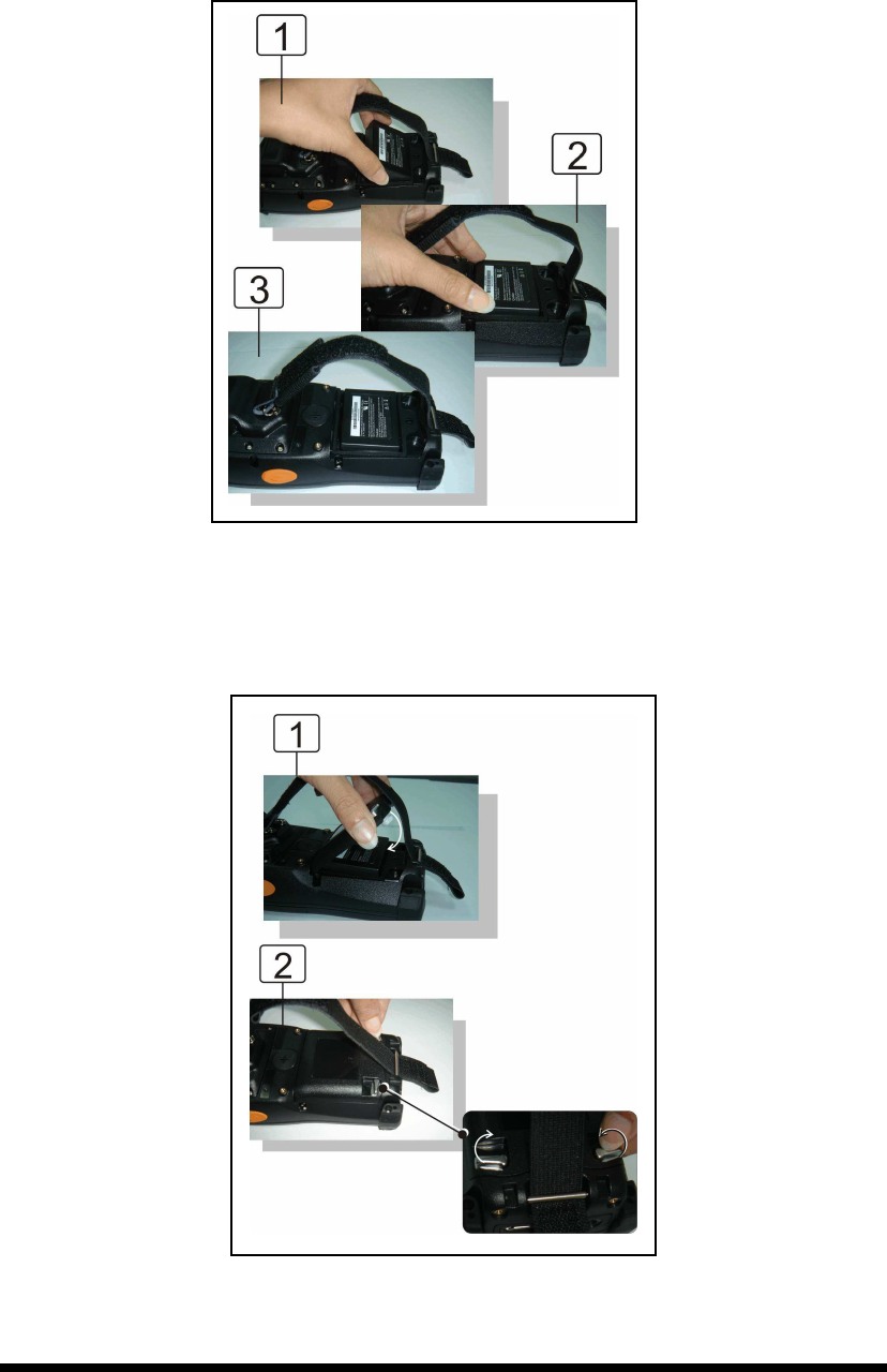
2-8
3. Insert the battery pack into the battery compartment with the label facing out, and
ensuring the battery snaps into place.
Figure 2-9 Insert the battery pack
4. Replace the battery cover by inserting the top first, and then press the bottom in firmly.
Turn the locking screws (right and left) upwards to secure the cover to the PDT.
Figure 2-10 Replace the battery cover
2-9
5. Charge time. For the first time to charge the battery pack needs approximately 6
hours. Subsequent charging time needs approximately 4 hours.
◆. When charging the battery pack, the charge LED indicator on the PDT turns on
Red. After the battery pack is fully charged, the charge LED indicator turns to
Green.
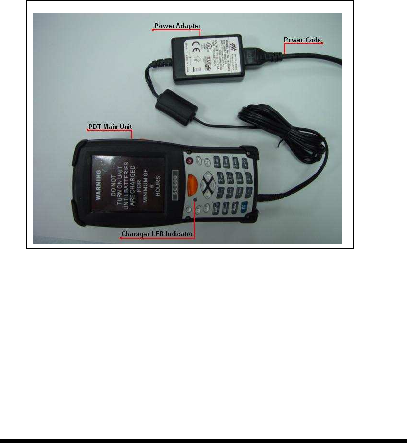
2.3.2 Charging the battery pack with Power Adapter
1. Connect the Power cord to the Power adapter.
2. Plug in the connector of the power adapter.
3. Connect the power cord to a power source.
Figure 2-11 Charging with power adapter
◆ When charging the battery pack, the charge LED indicator on the PDT turns on
Red.
◆ After the battery pack is fully charged, the charge LED indicator turns to Green.

2-10
2.4. Handling the PDT
2.4.1 Starting the PDT
Press the Power key to turn on/off the PDT. If the PDT does not power on, perform a
cold boot. See 2-7 Resetting the PDT.
CAUTION: When a battery is fully inserted in PDT for the first time, upon the
PDT’s first power up, the device boots and powers on automatically.
Figure 2-13 Starting the PDT
2.4.2 Power on / off
To turn on the PDT
Press the Power key briefly ( ). If the PDT does not power on, perform the cold
reset. See chapter 2.7.1.
As the PDT initializes its file system, it splash screen displays for about 30 seconds
followed by calibration screen. Every time you perform a cold reset, these screens will
also appear.
To turn off the PDT, just press the Power key again. This action does not actually turn off
the PDT, it only turns the PDT into suspend mode. All running applications remain as you
left them, until you press the Power key again to resume operation of the PDT
When the PDT is powered on for the first time,
it initializes its system. A splash screen (figure
2-13) appears for a short period of time
followed by the Wince.NET 4.2 window.
This section offers the basic procedures of PDT
using.
2-11
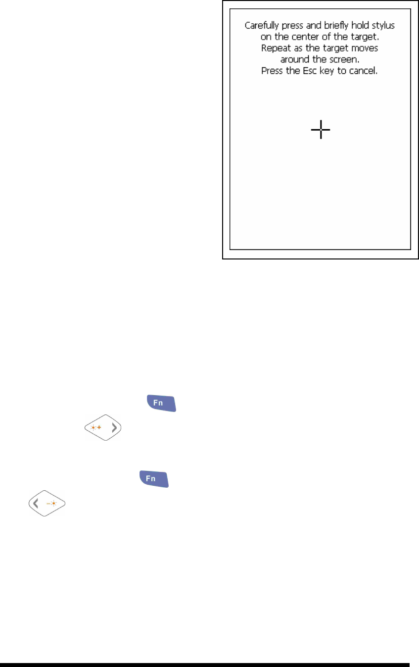
2.4.3 Calibration of the touch Screen
On the initial boot-up of the PDT, the stylus
calibration screen (Labeled Align Screen)
opens. Use the stylus to press and hold
briefly on the center of each target as it
moves around the screen.
If necessary, adjust the backlight on the PDT
to make the screen readable. (See below
2.4.4. Adjust the brightness).
When you feel the touch screen function is
poor or the operation does not match the
exact location it should be, please
recalibrate the screen by using the stylus to
tap the Start > Settings > Control Panel >
Stylus, to open the “Calibration” to
recalibrate again.
Figure 2-14 Calibration
2.4.4 Adjusting the brightness
The factory default for the brightness is in Middle level. You can adjust the brightness
to meet your environment and comfort as:
1) Become brighter: Press the
key and then press on the right key of
Navigation key .
2) Become darker: Press the
key and then press on the left key of Navigation
key .
3) The display will become dimmer automatically, if you do not perform any
operation for a specific period of time. This will help to save the battery power. You
can set up the specific period of time to see chapter 2.6 as reference.
2-12
2.4.5 To mute the Sound
To mute the sound, press the key first, and then press the key to turn
off and on of the sound.
2.4.6 Using the Stylus
The stylus is located next to hand-strap on the left rear of the PDT. The stylus function
is same as the mouse on a PC. Use the stylus to:
1) Navigate the display, select menu item and open optional applications.
2) Tap the characters on soft keyboard panel.
3) Hold the stylus on the screen and drag across the screen to select the list of multiple items.
CAUTION: Never use a pen, pencil, or other sharp object on the display to avoid any
unexpected damage of the touch screen.
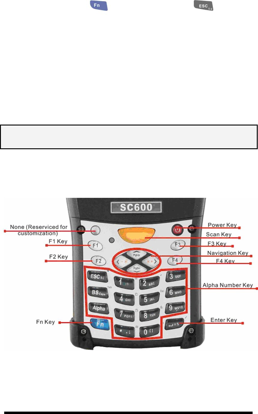
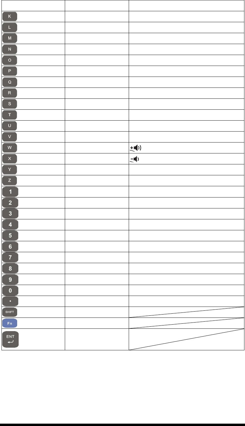
2.4.7 Using the SC600 Keypad
Figure 2-15 SC600 Keypad
2-13
Table 2-3 Keypad List
Key Main Function Fn + Main
Function
Alpha + Main
Function
None. (Reserved for
Customer)
Main Barcode Scan
Key
Power On/Off
Internet Explorer
Microsoft WordPad
Inbox
File Explorer
Right Backlight
Increase
Left Backlight
Decrease
Down Page Down
Up Page Up
ESC Audio Mute $
$$
$
€
Backspace TAB Caps
Change to letters
Function change
1 @
@@
@ :
::
:
\
\\
\
2 ’ A
AA
A
B
BB
B
C
CC
C
3 +
++
+ D
DD
D
E
EE
E
F
FF
F
4 Paste G
GG
G
H
HH
H
I
II
I
5 Del J
JJ
J
K
KK
K
L
LL
L
6 -
--
- (Minus Sign) M
MM
M
N
NN
N
O
OO
O
7 Copy P
PP
P
Q
QQ
Q
R
RR
R
S
SS
S
8 &
&&
& T
TT
T
U
UU
U
V
VV
V
9 *
**
* W
WW
W
X
XX
X
Y
YY
Y
Z
ZZ
Z
2-14
Key Main Function Fn + Main
Function
Alpha + Main
Function
0 Space 〔
〔〔
〔
〕
〕〕
〕
. (Point) Start Menu ,
,,
,
;
;;
;
Enter /
//
/ =
==
=
%
%%
%
Table 2-4 Special Assembler Key
Assembler Key
Functionality
Definition
Warm Reset Press “F1” and “F4” button simultaneously.
Cold Reset Press “Power”, “F1” and “F4” button
simultaneously.
Table 2-5 Definition of main Function
Key Main Function Definition
None.
Keep its function or by
customer demand
.
Main Barcode Scan
Key The key activates the scan
function of SC600.
Power On/Off
The key puts the terminal into and
wakes the terminal from suspend mode if
this key button is not pressed more than
two
seconds.
Internet Explorer Application key 1, User can define F1
function from setting.
Microsoft WordPad
Application key 2, User can define F2
function from setting.
Inbox Application key 3, User can define F3
function from setting.
File Explorer Application key 4, User can define F4
function from setting.
Right
Move the cursor one character to the right.
The cursor will move continuously if button
is pressed continuously.
Left Move the cursor one character to the left.
The cursor will move continuously if button
2-15
Key Main Function Definition
is pressed continuously.
Down
Move the cursor down one row or line The
cursor will move continuously if button is
pressed continuously.
Up
Move the cursor up one row or line The
cursor will move continuously if button is
pressed continuously.
ESC This key performs a cancel action
Backspace
“Backspace” key, it moves the cursor back
one space each time the key is pressed. It
deletes the previous character each time it
is
pressed if you are typing text. The cursor
will move continuously if button is pressed
continuously.
Change to letters
1. The key enables you to toggle
between the numeric and alpha modes.
Numeric mode is when you type numbers
with number keys. Alp
ha mode is when you
type letters with the number keys.
2. When you press key, it appears
“Alpha” icon at the Task bar to indicate
Alpha mode is enabled. The keypad stays in
the alpha mode until you press key
again.
Function change
The key is used
in combination with
other keys to type special characters and
perform system functions.
1 Number key “1”
2 Number key “2”
3 Number key “3”
4 Number key “4”
5 Number key “5”
2-16
Key Main Function Definition
6 Number key “6”
7 Number key “7”
8 Number key “8”
9 Number key “9”
0 Number key “0”
. Point key
Enter This key confirms data entry
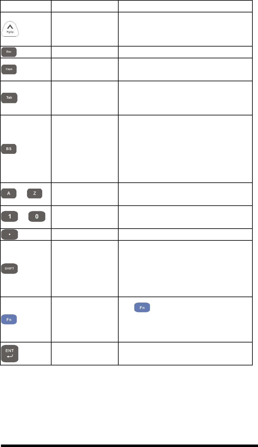
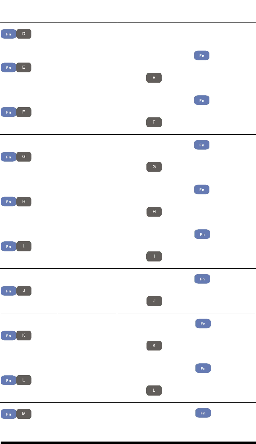
2.4.7.1 Special Function by “Fn” + main Function
The “Fn” key is used in combination with other keys to type special characters and
perform system functions.
Table 2-6 Special Function key define
Key
Sequence
Fn + Main
Function Definition
Increase of
Brightness
Increase the LED backlight brightness of
display screen(Lighter)
You must press key, then press
key to increase backlight
brightness each time.
Decrease of
Brightness
1. Decrease the LED backlight brightness
of display screen (darker)
2. You must press key, then press
key to decrease backlight
brightness each time.
Page Down
1. Move the cursor down one page. The
cursor will move continuously if button
is pressed continuously.
2. You must press key, then press
key to cursor down one page

2-17
Key
Sequence
Fn + Main
Function Definition
each time.
Page Up
1. Move the cursor up one page. The
cursor will move continuously if button
is pressed continuously.
2. You must press key, then press
key to cursor up one page each
time.
Audio Mute
1. Toggle the audio mute/on
2. You must press key, then press
key to enable audio mute or turn
on audio function each time.
TAB
1. The “TAB” function is to move the
cursor to the next tab stop or the next
control (on a form)
2. To do this function by pressing
key first, and then pressing key
each time.
@
Enter an @ by pressing key, then
pressing key.
’
Enter a {’} by pressing key, then
pressing key.
+
++
+ Enter a plus sign by pressing key,
then pressing key

2-18
Key
Sequence
Fn + Main
Function Definition
Paste
1. It is to do “Paste” function.
2. To do this function by pressing
key first, and then pressing key
each time.
Del
1. The “Delete” function delete the next
character forward each time.
2. To do “Delete” function by pressing
key first, and then pressing
key each time.
-
--
- (Minus Sign) Enter a minus sign by pressing key,
then pressing key.
Copy
1. Copy action.
2. You must press key, then press
key to do “Copy” action each
time.
&
&&
& Enter an AND sign by pressing
key,
then pressing key.
*
**
* Enter an asterisk sign by pressing
key first, and then pressing key.
Space
1. The “Space” function is to move the
cursor one space.
2. To do this function by pressing

2-19
Key
Sequence
Fn + Main
Function Definition
key first, and then pressing key
each time.
Start Menu
1. It displays the Start menu.
2. To do this function by pressing
key first, and then pressing key
each time.
/
//
/ Enter a slash by pressing key first,
and then pressing key.
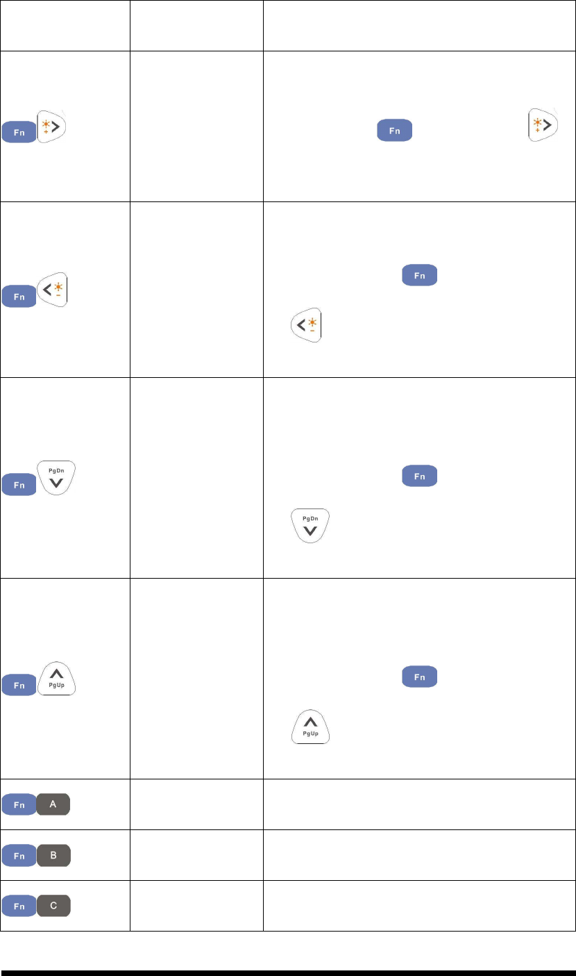
2.4.7.2 Alpha plane keys by “Alpha” + main Function
1. The key enables you to toggle between the numeric and alpha modes.
Numeric mode is when you type numbers with number keys. Alpha mode is
when you type letters with the number keys.
2. When you press key, it appears “Alpha” icon at the Task bar to
indicate Alpha mode is enabled. It means Alpha mode is disabled if there isn’t
“Alpha” icon at Task bar. The keypad stays in the alpha mode until you press
key again. For an example to type “cap1” word, press
< wait 0.5 seconds >
.
3. If you want to type a lowercase “c”, press
(The
key three times, the key is needed if it’s the first alpha
character keying in.). If a letter that is on the same key as the last letter entered,
wait two seconds after you pressed the last key, then you can enter the correct
series of keystrokes to create the next letter.

2-20
4. While you are in the Alpha mode and you press key to initial the Caps
mode, you will render a Caps Lock until you press key again. Once
you are in Caps mode, you stay in Caps until it is pressed again.
5. It appears “A” icon at Task Bar during Caps mode.
Table 2-7 Alpha + Numeric keys define
To
enter
Press the Keys To
enter
Press the Keys
$ €
Caps
:
::
: \
\\
\
a A
b B
c C
d D
e E
f F
g G
h H
i I
j J
k K
l L
m M
n N
o O
p P
q Q
r R
s
S
t T
u U
v V
w W
x X
2-21
To
enter
Press the Keys To
enter
Press the Keys
y Y
z
Z
〔 〕
, ;
= %
Note:
1. The key is not needed to key in if the character isn’t the first alpha
character being keyed in.
2. The keys are not needed to key in if it is not the first capital alpha
character being keyed in.
2.4.8 Using the SC620 Keypad
Figure 2-16 SC620 Keypad
2-22
Table 2-8 Keypad List
Key Main Function Fn + Main Function
None
Main Barcode Scan
Key
Power On/Off
Internet Explorer
Microsoft WordPad
Inbox
File Explorer
Right Increase of Brightness
Left Decrease of Brightness
Down Page Down
Up Page Up
Esc
Caps
Tab
Backspace
A F5
B F6
C F7
D F8
E (
F )
G [
H ]
I {
J }
2-23
Key Main Function Fn + Main Function
K €
L $
M #
N %
O ^
P ~
Q ,
R 、
、、
、
S !
T ?
U \
V =
W
X
Y ;
Z /
1 @
2 ’
3 +
++
+
4 Paste
5 Del
6 -
--
- (Minus Sign)
7 Copy
8 &
9 *
**
*
0 Start Menu
. (Point) Space
SHIFT
Function change
Enter
2-24
Table 2-9 Special Assembler Key
Assembler Key
Functionality
Definition
Warm Reset Press “F1” and “F4” button simultaneously.
Cold Reset Press “Power”, “F1” and “F4” button
simultaneously.
Table 2-10 Definition of main Function
Key Main Function Definition
None
Keep its function by customer demand.
Main Barcode Scan
Key The
key activates the scan
function of SC620.
Power On/Off
The key puts the terminal into and
wakes the terminal from suspend mode if
this key button is not pressed more than
two
seconds.
Internet Explorer Application key 1, User can define F1
function from setting.
Microsoft WordPad
Application key 2, User can define F2
function from setting.
Inbox Application key 3, User can define F3
function from setting.
File Explorer Application key 4, User can define F4
function from setting.
Right
Move the cursor one character to the right.
The
cursor will move continuously if button
is pressed continuously.
Left
Move the cursor one character to the left.
The cursor will move continuously if button
is pressed continuously.
Down
Move the cursor down one row or line The
cursor will move continuously if button is
pressed continuously.
2-25
Key Main Function Definition
Up
Move the cursor up one row or line The
cursor will move continuously if button is
pressed continuously.
Esc This key performs a cancel action
Caps Conversion of the capital & lower case of
the alpha key.
Tab
The “TAB” function is to move the cursor
to the next tab stop or the next control (on a
form)
Backspace
“Backspace” key, it moves the cursor back
one space each time the key is pressed. It
deletes the previous character each time it is
pressed if you are typing text. The cursor
will move continuously if button is pressed
continuously.
~
A ~ Z Use the alpha keys for alphabetic
characters.
~
1 ~ 0 Numeric value keys.
. Point key
SHIFT
Press and release the SHIFT key to activate
the keypad alternate SHIFT functions. The
icon appears on the taskbar. Press and
release the SHIFT key again to return to the
normal keypad functions.
Function change
The key is used in combination with
other keys to type special characters and
perform system functions.
Enter This key confirms data entry
2.4.8.1 Special Function by “Fn” + main Function
The “Fn” key is used in combination with other keys to type special characters and
perform system functions.
2-26
Table 2-11 Special Function key define
Key Sequence
Fn + Main
Function Definition
Increase of
Brightness
Increase the LED backlight brightness of
display screen(Lighter)
You must press key, then press
key to increase backlight brightness each
time.
Decrease of
Brightness
3. Decrease the LED backlight brightness of
display screen (darker)
4. You must press key, then press
k
ey to decrease backlight brightness
each time.
Page Down
3. Move the cursor down one page. The
cursor will move continuously if button is
pressed continuously.
4. You must press key, then press
key to cursor down one page each
time.
Page Up
3. Move the cursor up one page. The cursor
will move continuously if button is
pressed continuously.
4. You must press key, then press
key to cursor up one page each
time.
F5 (Barcode
Settings)
Application key 5, User can define F5
function from setting.
F6 (Media Player)
Application key 6, User can define F6
function from setting.
F7 (Calculator) Application key 7, User can define F7
function from setting.
2-27
Key Sequence
Fn + Main
Function Definition
F8 (Information) Application key 8, User can define F8
function from setting.
(
Enter a ( by pressing key, then
pressing key.
)
Enter a ) by pressing key, then
pressing key.
[
Enter a [ by pressing key, then
pressing key.
]
Enter a ] by pressing key, then
pressing key.
{
Enter a { by pressing key, then
pressing key.
}
Enter a } by pressing key, then
pressing key.
€
Enter a € by pressing key, then
pressing key.
$
Enter a $ by pressing key, then
pressing key.
# Enter a # by pressing key, then
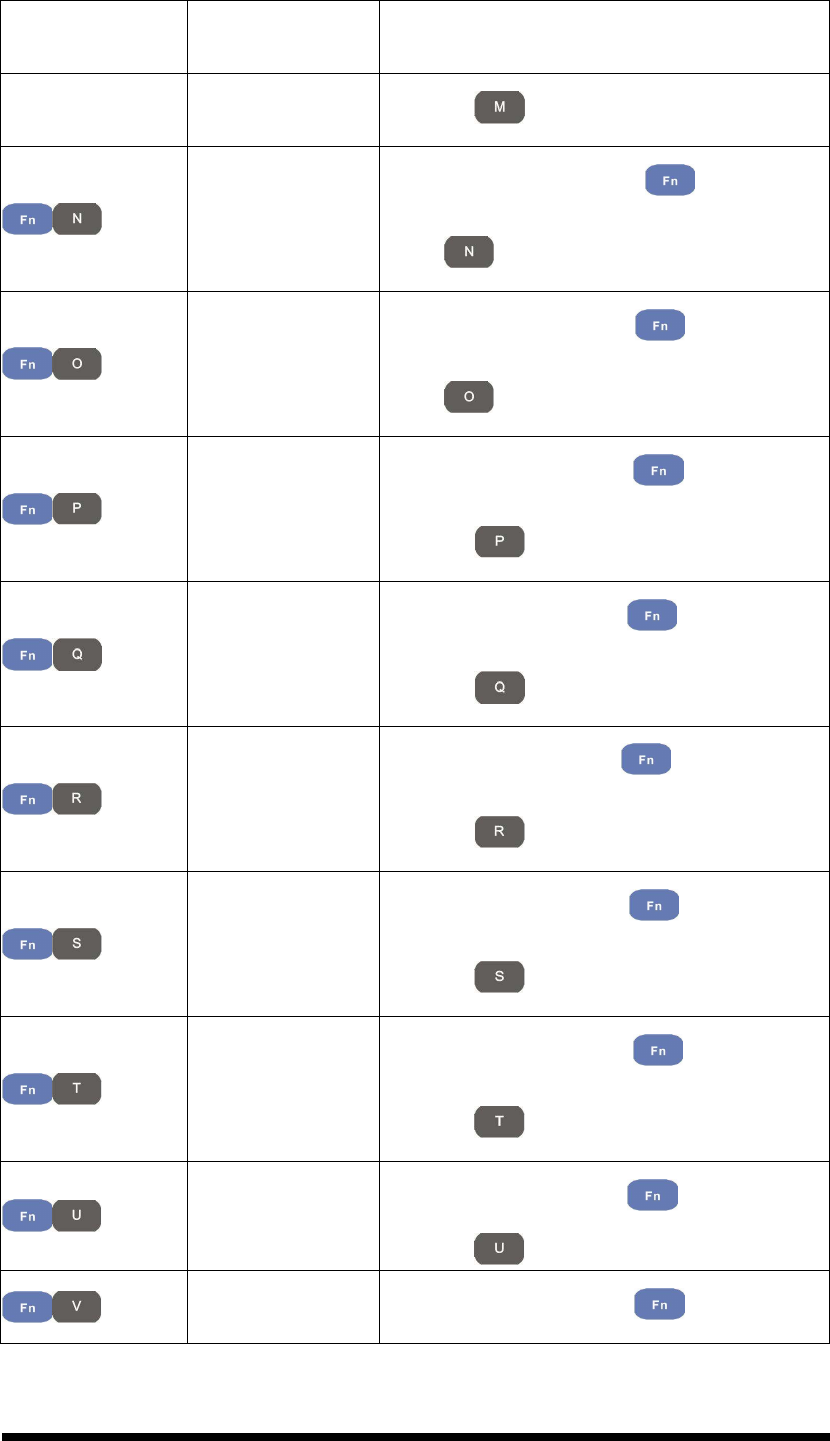
2-28
Key Sequence
Fn + Main
Function Definition
pressing key.
%
Enter a % by pressing key, then
press key.
^
Enter a ^ by pressing key, then
press key.
~
Enter a ~ by pressing key, then
pressing key.
,
Enter a , by pressing key, then
pressing key.
、
、、
、
Enter a 、
、、
、 by pressing key, then
pressing key.
!
Enter a ! by pressing key, then
pressing key.
?
Enter a ? by pressing key, then
pressing key.
\ Enter a \ by pressing key, then
pressing key.
= Enter a = by pressing key, then
2-29
Key Sequence
Fn + Main
Function Definition
press key.
Increases device volume, press key
and then press key.
Decreases device volume, press key
and then press key.
; Enter a ; by pressing key, then
pressing key.
/ Enter a / by pressing key, then
pressing key.
@
Enter a @ by pressing key, then
pressing key.
’
Enter a {’} by pressing key, then
pressing key.
+
++
+
Enter a plus sign by pressing key, then
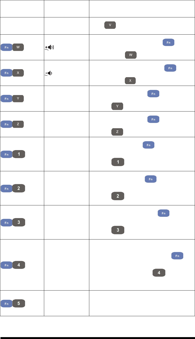
pressing key
Paste
3. It is to do “Paste” function.
4. To do this function by pressing
key
first, and then pressing key each
time.
Del
3. The “Delete” function delete the next
character forward each time.
4. To do “Delete” function by pressing
2-30
Key Sequence
Fn + Main
Function Definition
key first, and then pressing
key each time.
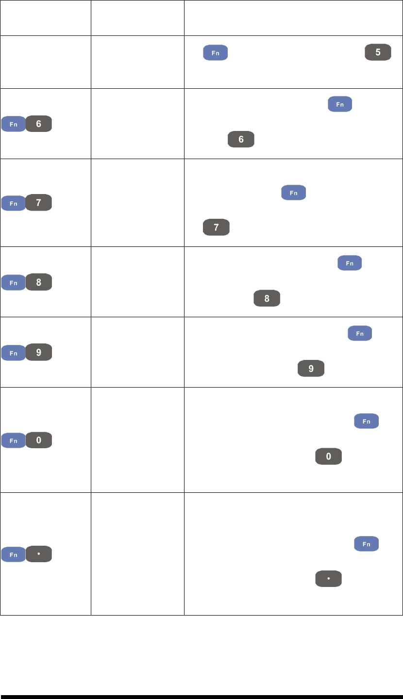
-
--
- (Minus Sign)
Enter a minus sign by pressing key, then
pressing key.
Copy
3. Copy action.
4. You must press key, then press
key to do “Copy” action each time.
&
&&
&
Enter an AND sign by pressing key,
then pressing key.
*
**
*
Enter an asterisk sign by pressing key
first, and then pressing key.
Start Menu
3. It displays the Start menu.
4. To do this function by pressing
key
first, and then pressing key each
time.
Space
3. The “Space” function is to move the
cursor one space.
4. To do this function by pressing
key
first, and then pressing key each
time.
2-31
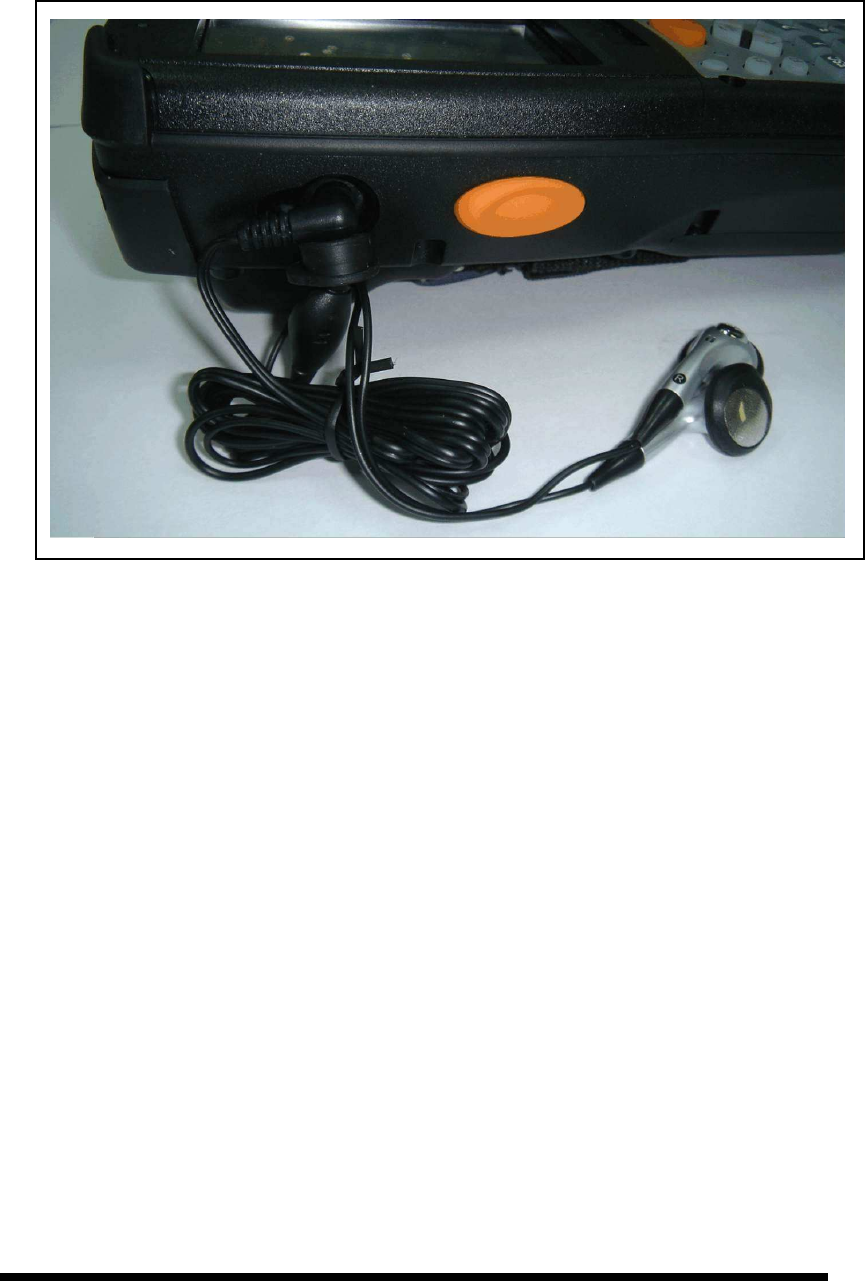
2.4.9 Using the Ear/Microphone
Connect Ear/Microphone to PDT earphone jack connector. The PDT is not built in
microphone; if you like to record the voice, you have to use Ear/Microphone.
Figure 2-17 Ear/Microphone
2-32
2.5 Navigating the Display
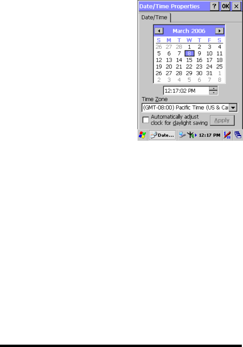
2.5.1 Setting Time and Date
In the Date/Time options, you can change the year, month, date, time, time zone, or
select automatic adjust for Daylight Saving Time. To set or change the date and time:
1. Select Start > Settings > Control Panel >
Date/Time
2. To change the year, select the year or open a
numeric dial. Select the up arrow to increase
the value; select the down arrow to decrease
the value. Or you can type a new value in
the field.
3. Select the month to open a pull-down list of
months or press the arrow buttons to either
side of the month to increase or decrease the
month.
Figure 2-18 Date/Time properties
4. To change the time, select the hour, minute, seconds, or AM/PM and select the up
arrow to increase the value; select /tape the down arrow to decrease the value. Or
you can type a new value in the field.
5. Select your correct time zone from the pull-down list.
6. To automatically adjust the clock for Daylight Saving Time, enable the checkbox
at the bottom of the screen.
7. Select Apply to make save your changes [and make additional modifications] or
select OK to exit the Date/Time settings.
2.5.2 Entering the Data
To select and open programs, select Start > Programs from the task bar to open a list
of available programs. Or if the program has a icon on the desktop, double-tap to open
it.
There are several ways to enter data on the PDT once in an application:
Use the keypad to enter alpha-numeric characters, Refer to “2.4.7 Using the
2-33
SC600 keypad”.
Use the stylus on the touch screen.
Select text in the same way you select the text on a PC. Use the stylus to
highlight the desired text by dragging the stylus across the desired text,
double-tapping to select one word and triple-rapping to select an entire
line/paragraph. Refer to “2.5 Navigating the Display” starting.
Use the soft input panel (digital keyboard) with the stylus.
Use the bar code scanning to enter data. Press the trigger or “Barcode Scan” key
to initiate a scan. The scanned data will enter the current application’s open file.
Refer to “2.5.7 Reading barcodes, 1D laser version” starting for more
information on using a scanner.
For more information on factory installed applications, Refer to Chapter 4 “ Software
Programs”.
2.5.3 The Command Bar
Use the Command bar at top of the screen to perform tasks in programs, such a
opening a file, or editing a file.
2.5.4 The Task Bar
The Task bar at the bottom of the screen displays the icon, an icon for the active
program, the current time, and system icons for utilities loaded in memory. The Task
bar includes menu names, buttons, and the keyboard icon, which opens and closes the
soft input panel (SIP). The Task bar allows you to select and close programs. Refer to
Figure 2-19 to view the Task bar.
Figure 2-19 Task Bar & Command Bar
Command Bar
Task Bar
2-34
2.5.5 The Soft Keypad
In applications that accept keypad input, the soft input panel (SIP) can be used to
enter data using the stylus. The SIP is digital, QWERTY-style keyboard.
To open the SIP, tap the keyboard icon to open the menu and select Hide Input
Panel to close the keyboard.
Use the stylus to select letters, numbers, or symbols from the Soft Input Panel for the
current application.
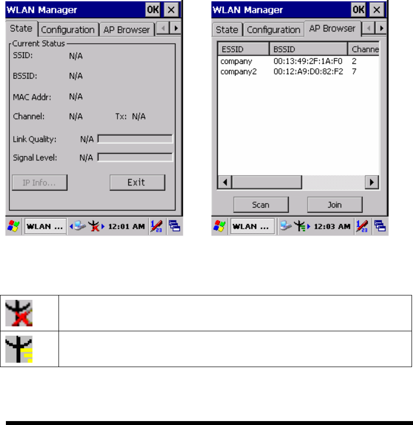
2.5.6 Setting Up Wireless LAN RF
1) Press “Start”---“Setting”---“Control Panel” --- “WLAN Manager”.
2) Launch the WLAN Manager to Enable WLAN device.
3) Into AP Browser tab, tap Scan button to renew the network.
4) Select a network, tap the Join button or double tap it for more options.
5) Press OK to save all your Wireless LAN settings.
6) Tap the “Exit” button to Disable WLAN device.
Figure 2-20 WLAN Manager Figure 2-21 WLAN Manager
Note:
802.11b WLAN is not connecting to network.
802.11b WLAN is no signal.
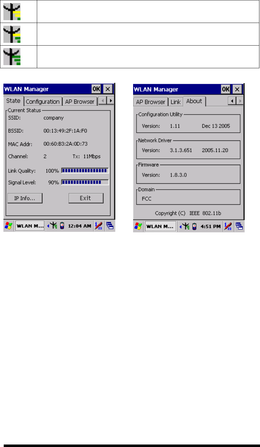
2-35
802.11b WLAN signal is Low.
802.11b WLAN signal is In General.
802.11b WLAN signal is Good.
Figure 2-22 WLAN Manager Figure 2-23 WLAN Manager
2.5.7 Reading barcodes, 1D laser version.
The 2D CMOS version can read both 1D and 2D bar codes. To use the scanning
function, complete the following steps:
1. If you have not already done so, remove the protective plastic film before using
devices equipped with a 2D CMOS bar code reader.
2.
Select Start > Setting > Control Panel > 2DBarcode; complete all configurations
following all description of Appendix A. 2D Barcode Setting.
3. Run the WordPad software program.
4. Press one of the three bar code reader trigger buttons.
5. Aim the scanning beam at the center of bar code. To assists in aiming, there are
4 green aiming light spots. The bar code should be between the outside 2 green
spots. The scanner is in focus in case the center 2 green spots joins into 1 spot.
2-36
5. Good scanning position.
The reading range is from 45 to 260mm distance.
1) Decrease the scanning distance to the bar code when scanning small
barcodes.
2) Increase the scanning distance from the bar code when scanning large
barcodes
3) The bar code should be located within the green light spots
4) The scanning area is visible by a red illumination area.
6. Bad scanning position.
1) Make sure that the laser beam sweeps across whole barcode.
2) Scanning operations may fail if the illumination beam is positioned as below.
7. Upon reading a bar code, the red LED indicator turns on until the trigger is
release or after five seconds. The green LED and the beep tone indicates a good
read.
2.5.8 Help
To tap “?” can get help information for each program.
2-37
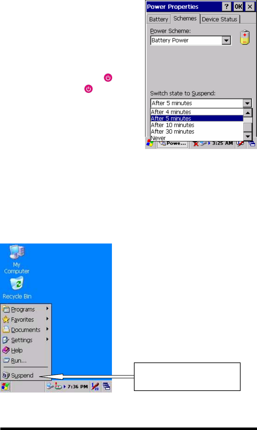
2.6 Power management
2.6.1 Suspend Mode
The PDT will go into a suspend mode when it
is idle for a period of time. The idle duration
can be customized using the Power control
panel (refer to Figure “Schemes Tab”)
Suspend mode works and looks just like you
have turned the unit off. Press the key to
suspend the PDT, Press the key again for
the PDT to resume its Previous state.
Use the Battery power control panel to set
the duration to switch state to Suspend mode
when system using battery power. This will
save battery power when PDT is not in use.
Figure 2-24 Schemes Tab
Suspending:
The following conditions will suspend:
Press <Power> key while the unit is on.
The duration timer of item “Switch state to Suspend” expires, which indicates
that there has been no use for a specified of time.
The battery pack is completely discharged.
Tap Start > Suspend
Tap here to let PDT enter into
suspend mode

2-38
2.6.2 Resuming
Use one of following methods to resume (wake up the PDT):
Press <Power> key to suspend or resume (wake up).
Put the PDT into a dock.
When a battery pack completely discharges while the unit is in suspend mode, the
PDT remains suspended until discharged battery condition is corrected.
2.7 Resetting the PDT
2.7.1 Software (Warm) Reset
A warm reset is a transition from the on, idle, or suspend power state that close all
applications, clears the working RAM, but preserves the file system.
Reason to Warm Reset: If an application “hangs”, initiate a warm reset to terminate
the application only.
Process to Warm Reset: To a warm reset, press “F1” and “F4” button
simultaneously.
After Warm Reset:
The desktop appears with the application shortcuts on the screen.
The custom settings in the registry are persistent.
2.7.2 Cold Reset
1) You can use Cold Reset to initiate device if WINCE.NET OS lock up or Warm
Reset still can’t work
2) To perform Cold Reset, press “Power”, “F1” and “F4” button simultaneously.
3) Device will initiate boot up after Cold Reset.
CAUTION: Only use the Warm Reset. Try warm reset before you initiate Cold
Reset. All applications will be Closed and working RAM and all files will be
cleared if you initiate the Cold Reset. It’s better usually to back up your files to
Flash ROM, Flash Card or PC.
3-1
Chapter 3. Setting
3.1 Introduction
To view available options for PDT’s setting, tap Start > Settings. Then, there are
three items inside Settings: “Control Panel”, “Network and Dial-up” and “Taskbar
and Start”.
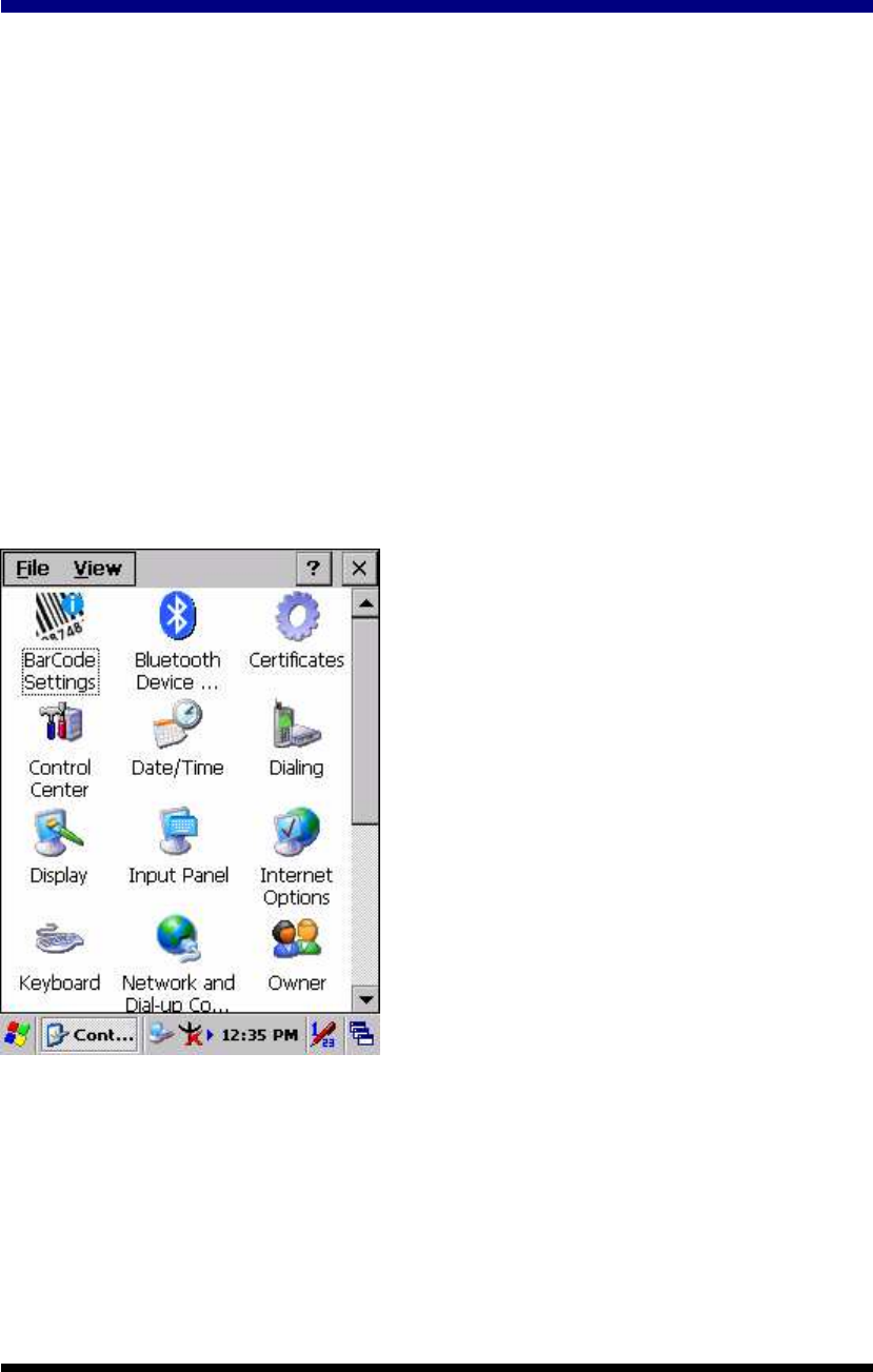
3.2 Control Panel
To view the Control Panel and settings you can modify by tapping Start > Settings >
Control Panel.
Figure 3-1 Control Panel
3-2
3.2.1 BarCode Setting
CAUTION:
::
:Please do not enter into any Barcode Application Program before
settings completing this Barcode.
There are three Tabs for scanner configuration setting: “Basic” Tab,
“Code Configure” Tab and “Code ID” Tab. In addition, there is
“BarCode Setup” for the “Code Configure” Tab.
3.2.1.1 “Basic” Tab
Figure 3-2 Basic Tab
Table 3-1 Basic Explaining
Field Name Function Explaining
Select the numbers of beep tone after scan OK.
None After scanning the barcode, do not give out
beep sound.
Beep After Scan
OK
One Time After scanning the barcode, give out beep
one time.

3-3
Field Name Function Explaining
Two Times After scanning the barcode, give out beep
two times.
Scan Timeout
(sec)
Select the scanning timeout duration (in seconds) from this
pull-down list. <2 ~ 20 sec, Default: 5>
None After showing barcode, do not action.
CRLF After showing the barcode, jump to next
row.
Space After showing the barcode, jump one unit.
Termination
Code
Tab After showing the barcode, jump a section.
Disable Disable this functionality.
Continuous
Scan 1 ~5 sec Alternate second number of Continuous
Scan.
Select a method based upon the barcode scanning application
you will use.
Type Writing A unit continues a unit, fast showing
barcode number.
Copy & Paste Once show barcode number.
Keybd Message
Disable Not show the barcode number.
Prefix Type the desired label prefix in this text box
Suffix Type the desired label suffix in this text box
Default Press “Default” button to reset all configuration setting of
“Basic” Tab into default values.
F/W ver. Decoder firmware version.
Set All To
Default
Press “Set All To Default” button to reset all configuration
setting of “Basic” Tab, “Code Configure” Tab, “Code ID” Tab
and all barcode of “BarCode Setup” into default values.
3-4
3.2.1.2 “Code Configure” Tab:
Select the barcode symbologies you plan to scan from the list. Tap to enable/disable
the desired symbologies.
Figure 3-3 Code Configure Tab
Table 3-2 Code Configure Explaining
Barcode Symbology Explaining
Type A. Numeric-only Barcodes
UPC-E
Compressed version of UPC code for use on small
products.
UPC-A Universal product code seen on almost all retail
products in the USA and Canada.
EAN-13 / ISBN EAN-13: European Article Numbering
international retail product code.
ISBN: Special use of the EAN-13 symbol to used
internationally to mark books.
EAN-8 / JAN-8 Compressed version of EAN code for use on
small products.
UPC-EAN Add-ON 2/5 UPC-A, UPC-E, EAN-13, and EAN-8 may all
include an additional barcode to the right of the
main barcode. This second barcode, which is
usually not as tall as the primary barcode, is used
to encode additional information for newspapers,
3-5
books, and other periodicals.
Industrial 2 of 5 / IATA Older code not in common use.
Interleaved 2 of 5 Compact numeric code, widely used in industry,
air cargo, other applications.
Plessey / MSI Plessey: Older code commonly used for retail
shelf marking.
MSI: Variation of the Plessey code commonly
used in USA.
Code 11 Used primarily for labeling telecommunications
equipment.
Codabar / NW 7 Older code often used in library systems,
sometimes in blood bank.
Matrix 2 of 5 Used in miscellaneous industrial applications, and
mechanical numbering systems.
Type B. Alphanumeric Barcodes
Code 39 / Code32 General-purpose code in very wide use
world-wide.
Code 93 Compact code similar to Code 39.
Code128 / UCC EAN128
Very capable code, excellent density, high
reliability; in very wide use world-wide.
Widely used data formatting model for Code 128
Type C. Others Barcodes
China Post Used by China Postal Service for automated mail
sorting.
Code 4 ---
GTIN Global Trade Identification Number
Korea Code 3 of 5 ---
RSS Reduced Space Symbology
3-6
3.2.1.3 “Code ID” Tab:
Figure 3-4 Code ID Tab
Table 3-3 Code ID Explaining
Code ID is added into prefix of the barcode and let user identify which kind of
barcode being scanned.
Enable Code ID Enable this functionality.
Set 1 ~ Set 5 Select one default value by Set 1 ~ Set 5.
(See the “Table 3-4 Code ID Set1-Set5 Table”)
User Define Establish number by oneself.
Barcode List Set 1 ~ Set 5: defaults setting.
User Define: select barcode to define.
Default Press “Default” button to reset all configuration
setting of “Code ID” Tab into default values.
Table 3-4 Code ID Set1-Set5 Table
Set 1 Set 2 Set 3 Set 4 Set 5
UPC-E S E C E E
UPC-A M A A A E
EAN-13 / ISBN M A A F E
EAN-8 / JAN-8 P B B F E
Industrial 2 of 5 / IATA C H H H S
Interleaved 2 of 5 D I Z I S
3-7
Set 1 Set 2 Set 3 Set 4 Set 5
Plessey / MSI V V D P M
Code 11 J J J J J
Codabar / NW 7 F N X N F
Matrix 2 of 5 E G G G S
Code 39 / Code 32 A C Y M A
Code 93 I L L L G
Code 128 H K K K C
Code 4 U U U U U
Korea Code 3 of 5 R R R R R
RSS R R R R R
UCC128 / EAN128 W W W W W
3.2.1.4 BarCode Setup
A. First select barcode type then select barcode to setting.
B. Press “Default” button to reset all configuration setting of this barcode into default
values.
C. Press “Apply” button to be decided setting of this barcode.
Please see 3.2.2 Symbologies List for more detail information of each Barcode.
Figure 3-5 BarCode Setup
3-8
3.2.2 Symbologies List
A Type -- Numeric-only Barcodes
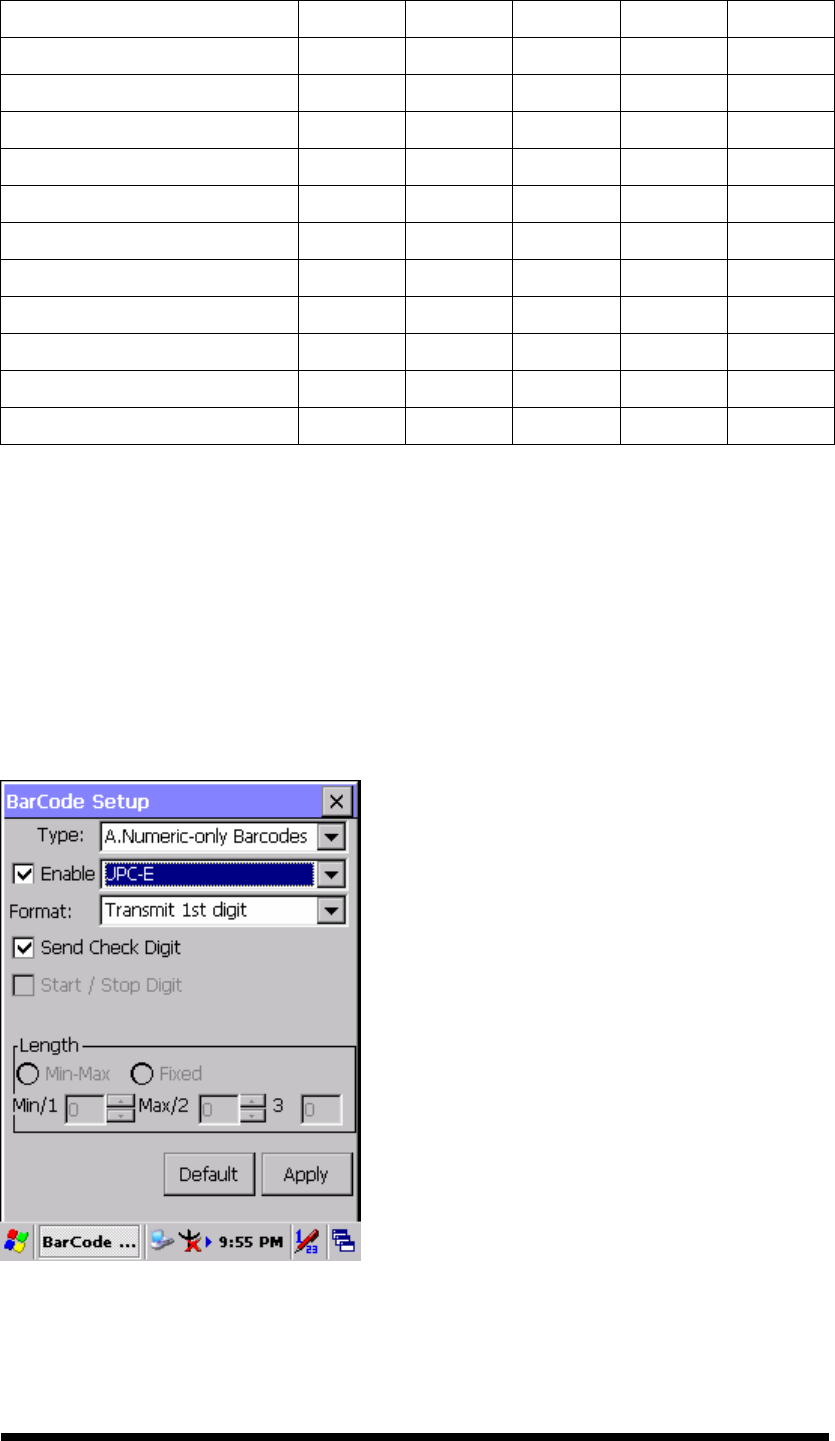
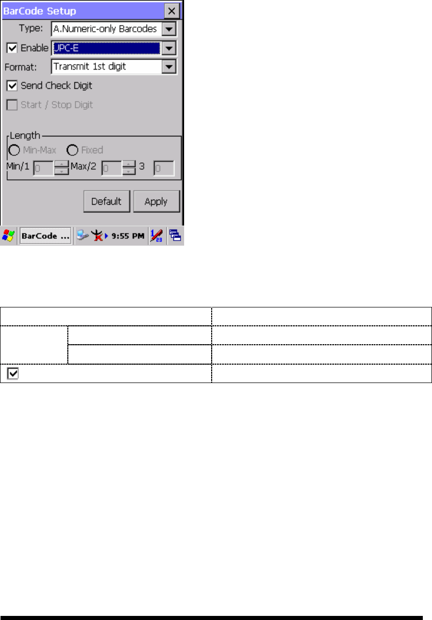
3.2.2.1 UPC-E
Figure 3-6 UPC-E
Table 3-5 UPC-E Explaining
Item Explaining
Ignore 1st digit Do not transmit 1st digit by barcode.
Format Transmit 1st digit Transmit 1st digit by barcode.
Send Check Digit Whether send check digit by barcode.
3-9
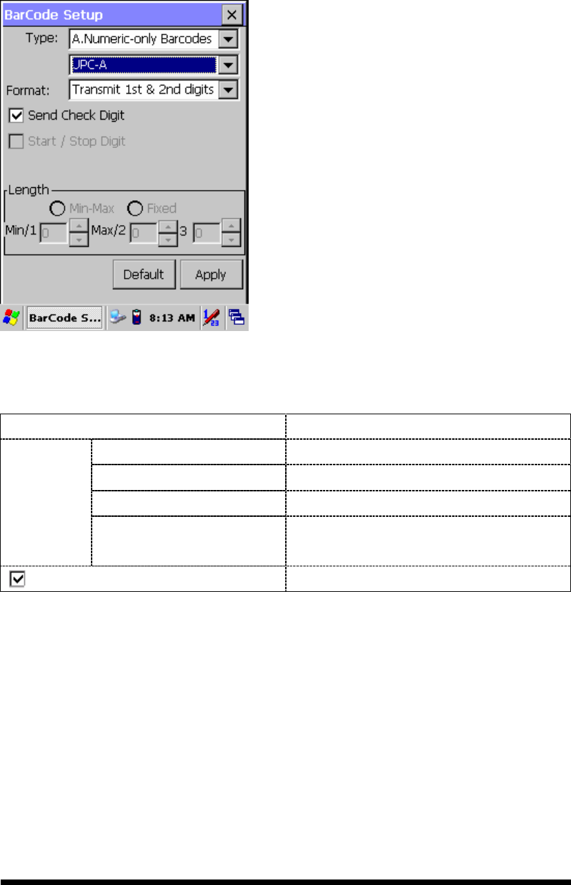
3.2.2.2 UPC-A
UPC-A movements together with EAN-13, so only Enable EAN-13 then UPC-A will
be Enable, too.
Figure 3-7 UPC-A
Table 3-6 UPC-A Explaining
Item Explaining
Ignore 1st & 2nd digits Do not transmit 1st digit by barcode.
Transmit 1st digit Transmit 1st digit by barcode.
Transmit 2nd digit Transmit 2nd digit by barcode.
Format
Transmit 1st & 2nd
digits Transmit 1st & 2nd digits by barcode.
Send Check Digit Whether send check digit by barcode.
3-10
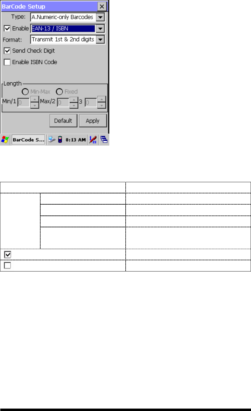
3.2.2.3 EAN-13 / ISBN
Figure 3-8 EAN-13 / ISBN
Table 3-7 EAN-13 / ISBN Explaining
Item Explaining
Ignore 1st & 2nd digits Do not transmit 1st digit by barcode.
Transmit 1st digit Transmit 1st digit by barcode.
Transmit 2nd digit Transmit 2nd digit by barcode.
Format
Transmit 1st & 2nd
digits Transmit 1st & 2nd digits by barcode.
Send Check Digit Whether send check digit by barcode.
Enable ISBN Code Whether use this ISBN Code.
3-11
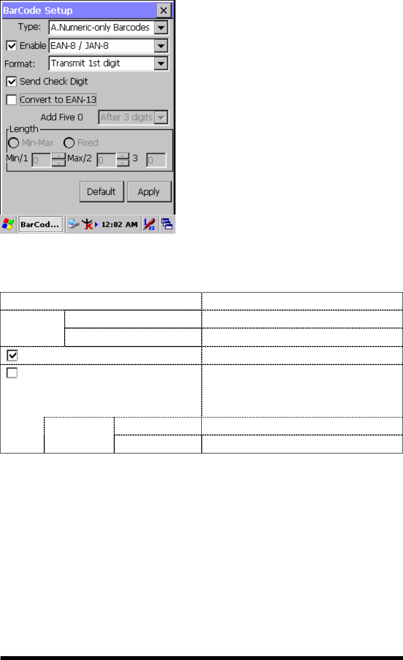
3.2.2.4 EAN-8/JAN-8
Figure 3-9 EAN-8/JAN-8
Table 3-8 EAN-8/JAN-8 Explaining
Item Explaining
Ignore 1st digit Do not transmit 1st digit by barcode.
Format Transmit 1st digit Transmit 1st digit by barcode.
Send Check Digit Whether send check digit by barcode.
Convert to EAN-13 When this option is selected the scanner
will convert EAN-8 to EAN-13 by
transmitting five zeroes …
Ahead of code Add five zeroes at prefix of the barcode.
Add five 0
After 3 digits Add five zeroes after 3rd digits.
3-12
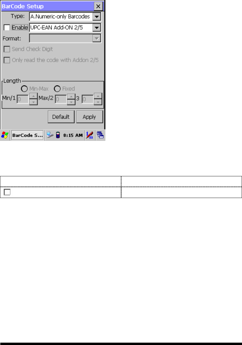
3.2.2.5 UPC-EAN Add on 2/5
A. UPC-E, UPC-A, EAN-13 / ISBN and EAN-8 / JAN-8 may all include an
additional barcode to the right of the main barcode.
B. This barcode will show primary & additional code together.
C. So the UPC-EAN Add-ON 2/5 code is unable to use alone, must operate in
UPC-E or UPC-A or EAN-13 / ISBN or EAN-8 / JAN-8.
Figure 3-10 UPC-EAN Add on 2/5
Table 3-9 UPC-EAN Add-On 2/5 Explaining
Item Explaining
Only read the code with Addon 2/5
Only reads the codes that have addenda.
3-13
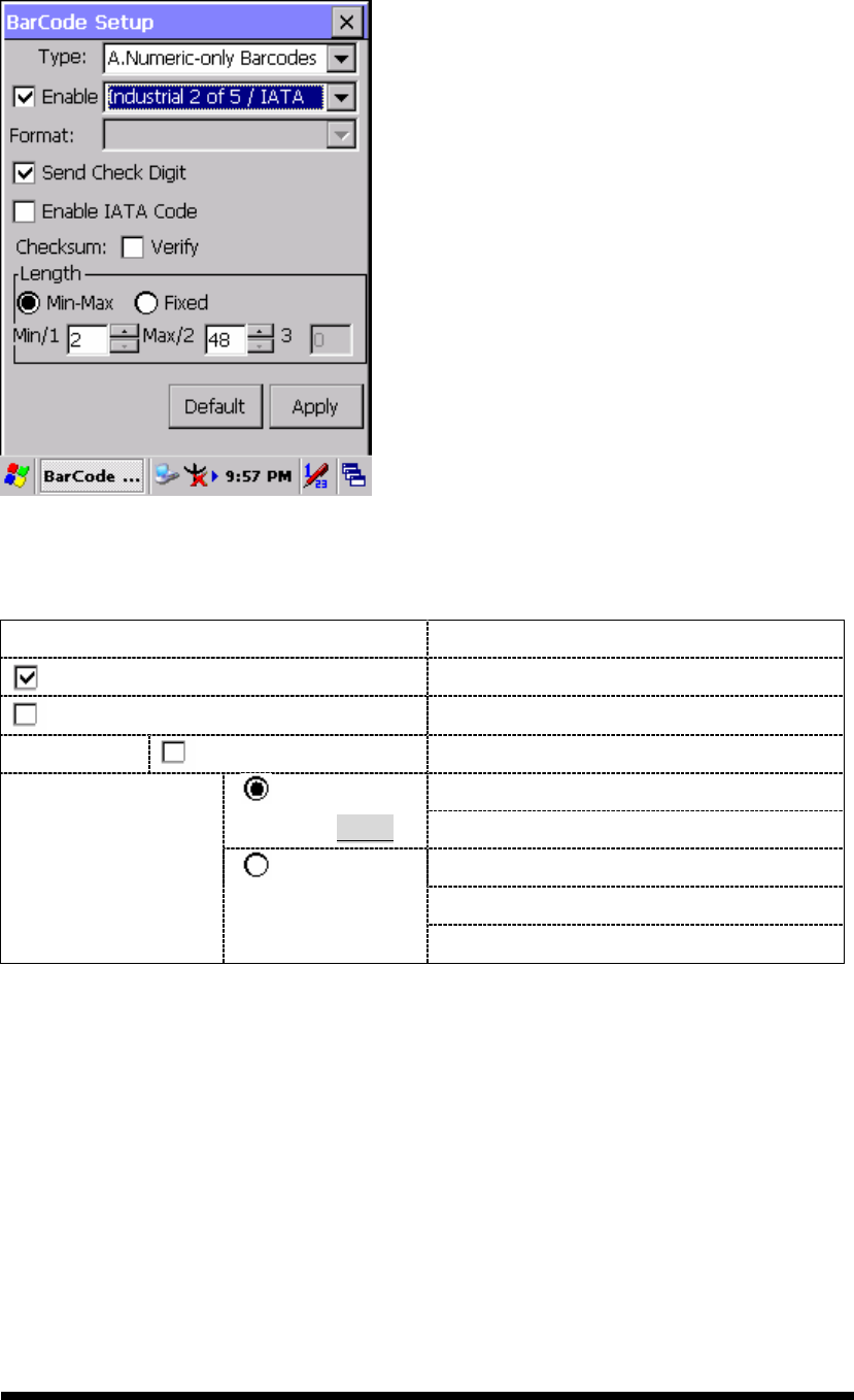
3.2.2.6 Industrial 2 of 5 / IATA
Figure 3-11 Industrial 2 of 5 / IATA
Table 3-10 Industrial 2 of 5 / IATA Explaining
Item Explaining
Send Check Digit Whether send check digit by barcode.
Enable IATA Code Whether use this IATA Code.
Checksum Verify Whether verify checksum by barcode.
Min Length can be set from 2 to 48
Min-Max
(Default: 2 / 48) Max Length can be set from 2 to 48
Length 1 can be set from 2 to 48
Length 2 can be set from 2 to 48
Length
Fixed
Length 3 can be set from 2 to 48
3-14
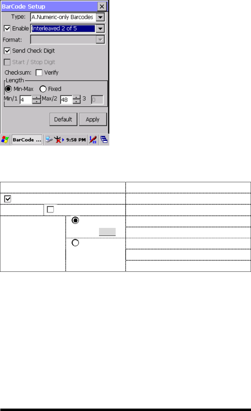
3.2.2.7 Interleaved 2 of 5
Figure 3-12 Interleaved 2 of 5
Table 3-11 Interleaved 2 of 5 Explaining
Item Explaining
Send Check Digit Whether send check digit by barcode.
Checksum Verify Whether verify checksum by barcode.
Min Length can be set from 4 to 48
Min / Max
(Default: 4 / 48) Max Length can be set from 4 to 48
Length 1 can be set from 4 to 48
Length 2 can be set from 4 to 48
Length
Fixed
Length 3 can be set from 4 to 48
3-15
3.2.2.8 Plessey / MSI
Figure 3-13 Plessey / MSI
Table 3-12 Plessey / MSI Explaining
Item Explaining
Mode 10
Mode 10-10
Format
Mode 11-10
Checksum mode for this barcode.
Send Check Digit Whether send check digit by barcode.
1 Digit Check 1 digit & send by checksum.
2 Digits Check 2 digits & send by checksum.
3-16
3.2.2.9 Code11
Figure 3-14 Code 11
Table 3-13 Code 11 Explaining
Item Explaining
Send Check Digit Whether send check digit by barcode.
1 Digit Check 1 digit & send by checksum.
2 Digits Check 2 digits & send by checksum.
3-17
3.2.2.10 Codabar / NW7
Figure 3-15 Codabar / NW7
Table 3-14 Codabar / NW7 Explaining
Item Explaining
Start / Stop Digit Whether transmit Start & Stop Digit.
ABCD
abcd
TN*E
tn*e
Start / Stop transmit type
Checksum Verify Whether verify checksum by barcode.
3-18
3.2.2.11 Matrix 2 of 5
Figure 3-16 Matrix 2 of 5
Table 3-15 Matrix 2 of 5 Explaining
Item Explaining
Send Check Digit Whether send check digit by barcode.
Checksum Verify Whether verify checksum by barcode.
Min Length can be set from 4 to 48
Min-Max
(Default: 4 / 48) Max Length can be set from 4 to 48
Length 1 can be set from 4 to 48
Length 2 can be set from 4 to 48
Length
Fixed
Length 3 can be set from 4 to 48
3-19
B Type -- Alphanumeric Barcodes
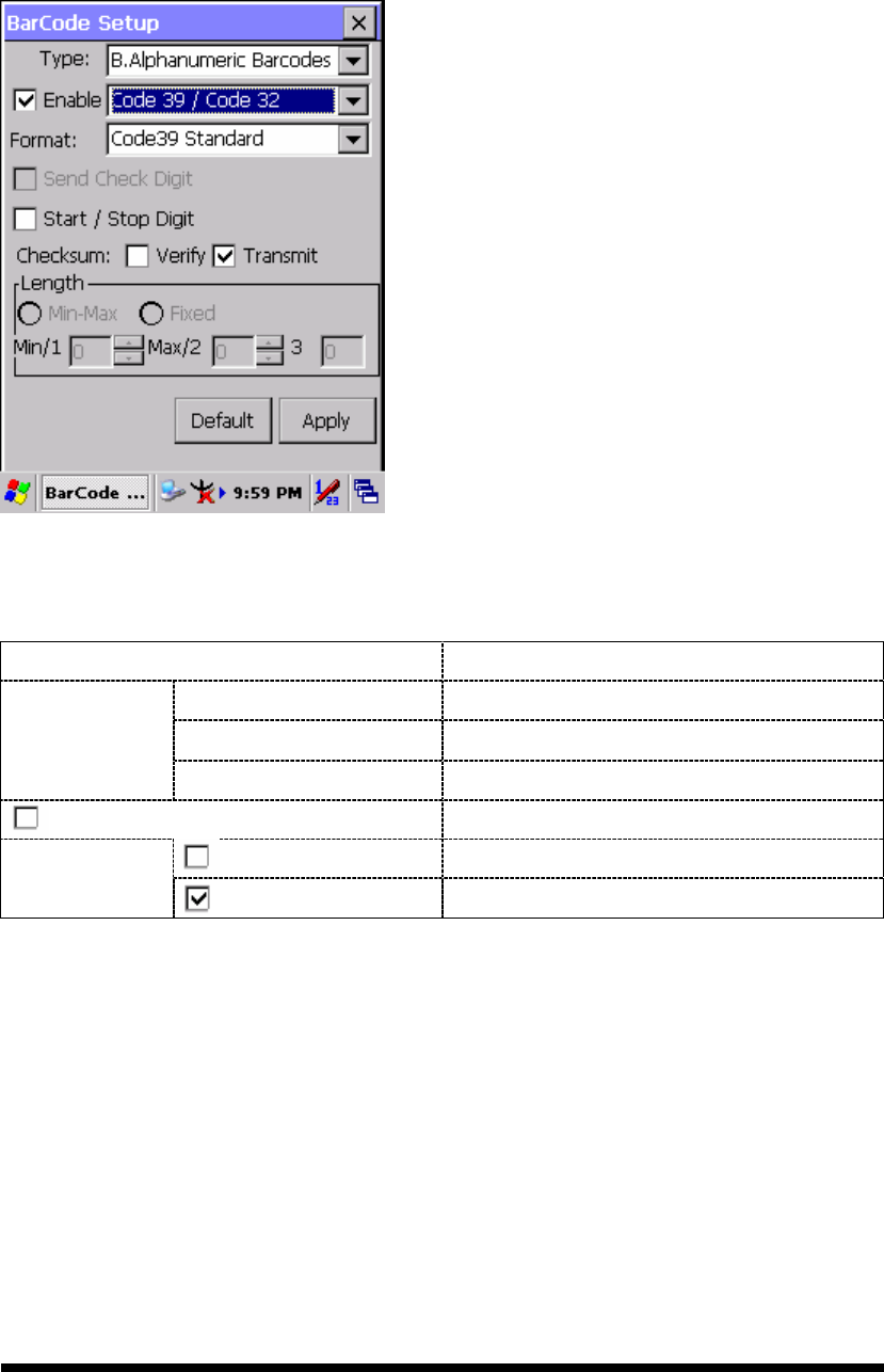
3.2.2.12 Code39 / Code32
Figure 3-17 Code39 / Code32
Table 3-16 Code39 / Code32 Explaining
Item Explaining
Code39 Standard Enable Code 39 Standard characters
Code39 Full ASCII Enable Code 39 Full ASCII character
Format
Code32 Enable Code 32
Start / Stop Digit Whether transmit Start & Stop Digit.
Verify Whether verify checksum by barcode.
Checksum Transmit Whether transmit checksum by barcode.
3-20
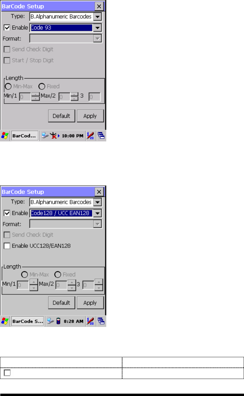
3.2.2.13 Code93
The barcode do not have setting.
Figure 3-18 Code93
3.2.2.14 Code128 / UCC EAN128
Figure 3-19 Code 128 / UCC EAN128
Table 3-17 Code128 / UCC EAN128 Explaining
Item Explaining
Enable UCC128/EAN128 Enable UCC128/EAN128.
3-21
C Type -- Others Barcodes
3.2.2.15 China Post
Figure 3-20 China Post
Table 3-18 China Post Explaining
Item Explaining
Checksum Verify Whether verify checksum by barcode.
Send Check Digit Whether send check digit by barcode.
Min Length can be set from 4 to 48
Min-Max
(Default: 4 / 48) Max Length can be set from 4 to 48
Length 1 can be set from 4 to 48
Length 2 can be set from 4 to 48
Length
Fixed
Length 3 can be set from 4 to 48
3-22
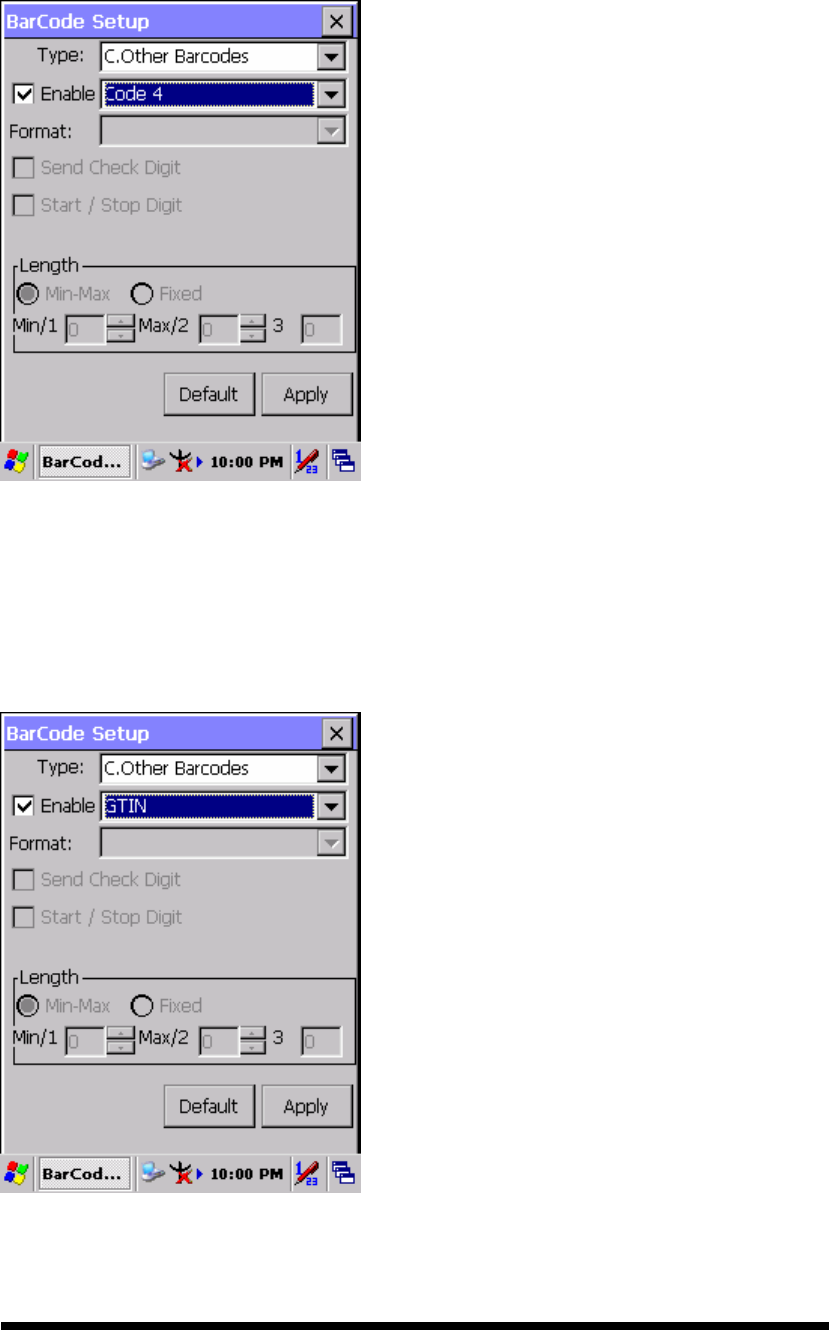
3.2.2.16 Code4
The barcode do not have setting.
Figure 3-21 Code4
3.2.2.17 GTIN
The barcode do not have setting.
Figure 3-22 GTIN
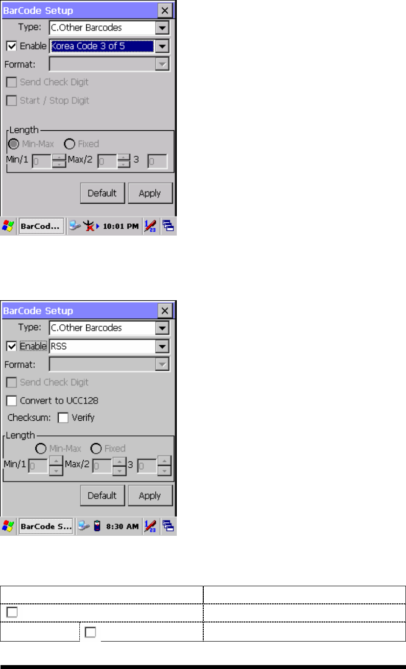
3-23
3.2.2.18 Korea Code 3 of 5
The barcode do not have setting.
Figure 3-23 Korea Code 3 of 5
3.2.2.19 RSS
Figure 3-24 RSS
Table 3-19 RSS Explaining
Item Explaining
Convert to UCC128
The scanner will convert RSS to UCC128.
Checksum Verify Whether verify checksum by barcode.
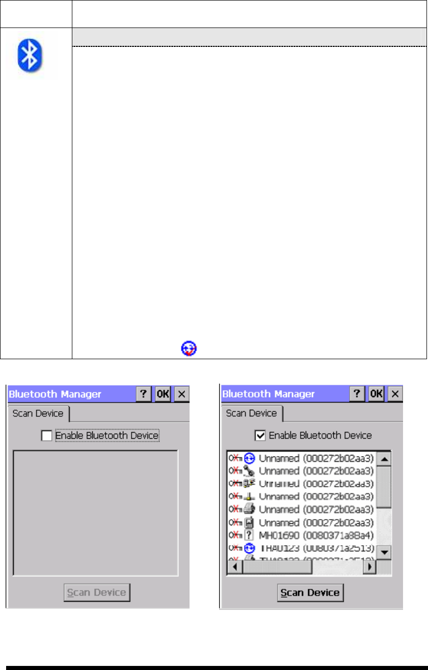
3-24
3.2.3 Bluetooth Device Properties
Table 3-20 Bluetooth Device Properties
ICON
ITEM & FUNCTION
“Scan Device” Tab ( Figure 3-25) :
Tap the Scan Device button to initiate a scan for Bluetooth
hardware. The Bluetooth manager lists the Bluetooth devices
that it finds, see Figure 3-26. If Bluetooth hardware is not found
the Bluetooth Hardware Error window appears, see Figure
3-27. Table 3-21 described the Bluetooth Icons.
Double tap the device to connect to on the device list. The
Bluetooth Manager Authentication window appears. Tap No to
connect to the device without authentication, or tap Yes to
authenticate the device before connecting. (Figure 3-28)
If the Yes button was selected in the Bluetooth Manager
Authentication window, the enter PIN windows appears. Enter a
PIN (between 1 and 16 characters) in the Enter PIN: text box,
and tap OK. The mobile computer sends the PIN request to the
device for bonding. (Figure 3-29)
When prompted, the same PIN must be entered on the other
device. When the PIN is entered correctly on the other device,
the bonded icon appears on the device list. (Figure 3-30)
Figure 3-25 Bluetooth Manager Windows Figure 3-26 Bluetooth Manager Windows
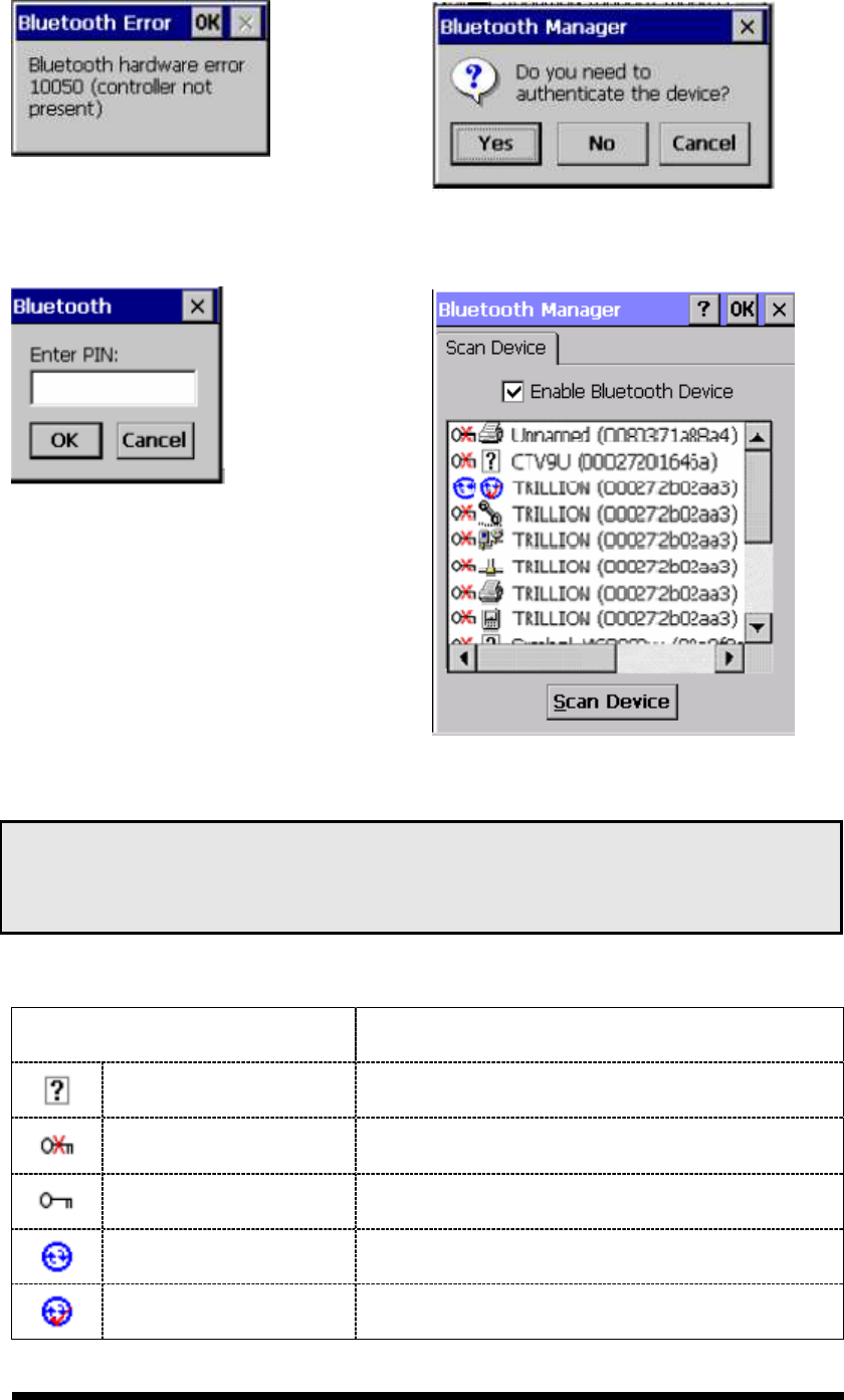
3-25
Figure 3-27 Bluetooth Error Windows Figure 3-28 Bluetooth Manager Windows
Figure 3-29 Bluetooth Enter PIN Windows Figure 3-30 Bluetooth Manager Windows
Note:
If the device to which the mobile computer is bonding does not appear in the list,
ensure it is turned on, in discoverable mode, and within range (30 feet / 10 meters) of the
mobile computer.
Table 3-21 Bluetooth Icon
Icon Description
Unknown device icon Device is not defined
Locked icon Device is locked and cannot be bonded to.
Not locked icon Device is not locked and can be bonded to.
Bluetooth device icon Bluetooth device
Bonded device icon Bonded Bluetooth device
3-26
Icon Description
Mobile device icon Device is a mobile device
Phone icon Device is a phone.
Printer icon Device is a printer
Network icon Device is a network.
Linked icon Device is linked.
3.2.4 Certificates
Certificates are used by some applications for establishing trust and for secure
communications.
Certificates are signed and issued by certificate authorities and are valid for a
prescribed period of time. Windows CE manages multiple certificate stores.
Table 3-22 Certificates
ICON
ITEM & FUNCTION
“Store” Tab ( Figure 3-31) :
In the Stores tab, select the certificate store you wish to view or
modify from the drop-down list (Figure 3-32).
The “Trusted Authorities “store lists the top-level certificates
for authorities you trust.( Figure 3-33 , Figure 3-34)
The “My Certificates “store contains your personal certificates,
which you use to identify yourself.
Intermediate certificate authorities that help establish a chain of
trust are stored in the “Other Authorities” store.
“Store” Tab :
To add a certificate or associated private key to the selected
store, select “Import” (Figure 3-35).
To view more details of the selected certificate, such as the
expanded name or expiration date, choose “View”.
To delete the selected certificate from the store, choose
“Remove”.
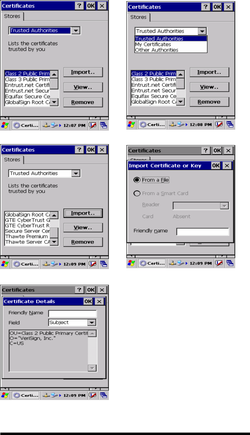
3-27
Figure 3-31 Certificates Figure 3-32 Certificates
Figure 3-33 Certificates
Figure 3-34 Certificates
Figure 3-35 Certificates
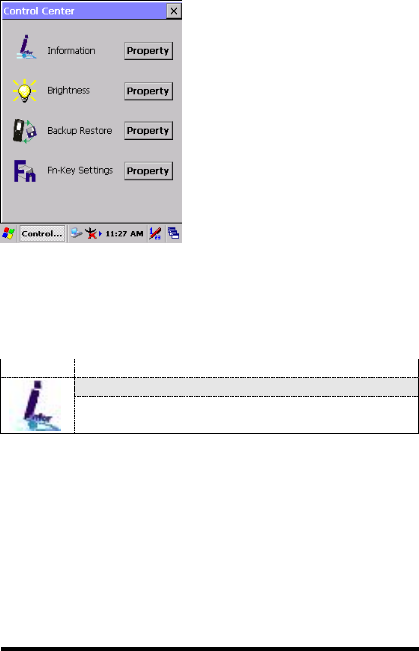
3-28
3.2.5 Control Center
The Control Center includes four AP, listed the following ......
Figure 3-36 Control Center
3.2.5.1 Information
Table 3-23 Information
ICON ITEM & FUNCTION
“Information” Tab :
Provide Software version, MAC address, Bluetooth ID, Serial
No. and Configuration No.
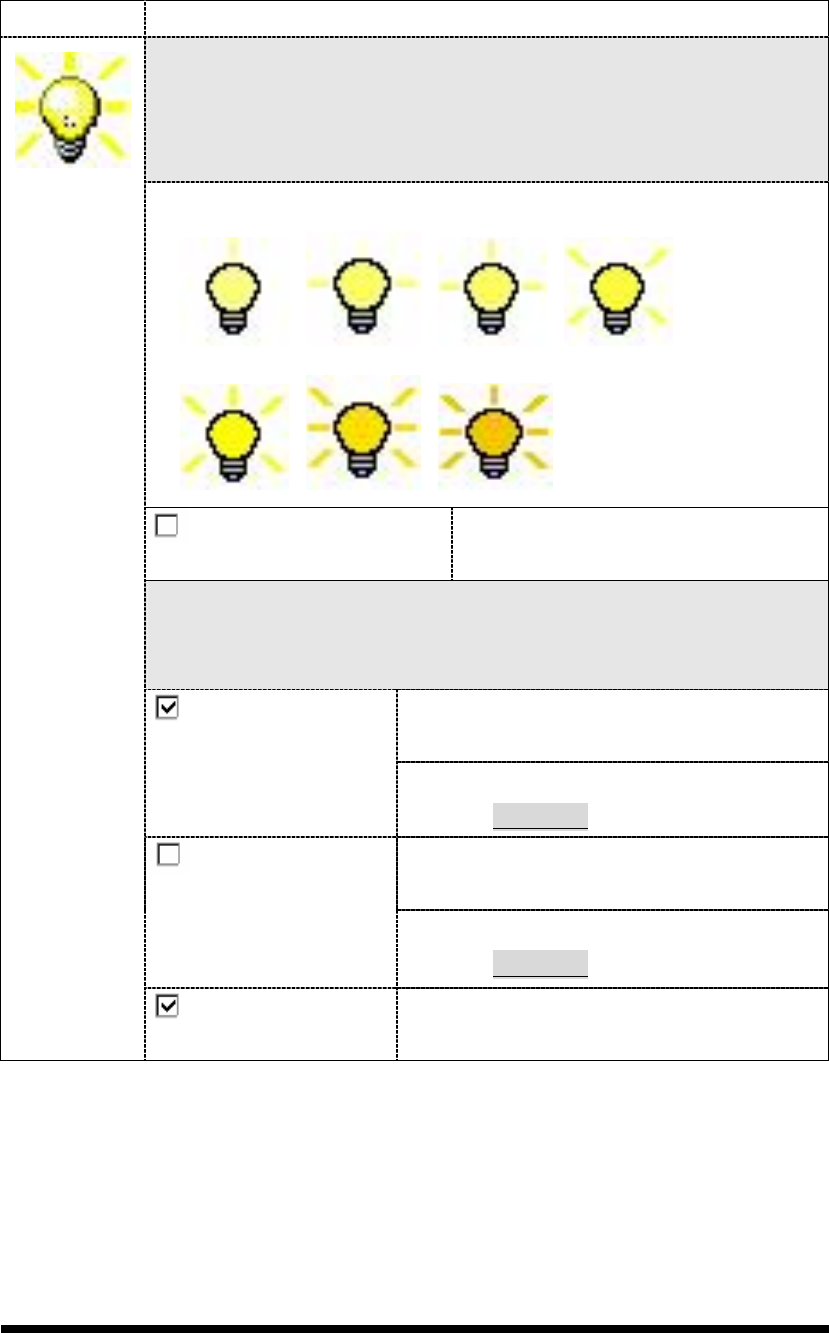
3-29
3.2.5.2 Brightness
Table 3-24 Brightness
ICON ITEM & FUNCTION
LCD Brightness
Tune the LCD brightness by tapping right-arrow & left-arrow. Can
also tune the LCD brightness by pressing right-direction key or
left-direction key of keypad.
Amounts 7 steps: Every step have corresponding picture of self.
1. 2. 3. 4.
5. 6. 7.
Enable Keypad
Brightness
Open keypad brightness or not.
Backlight Timeout
Save battery life by automatically turning off the backlight when not
used.
The table must disable when its item is not
marked.
Battery
Power, turn
off backlight after
The table has 15 seconds, 30 seconds, 1
minute, 2 minutes and 5 minutes.
The table must disable when its item is not
marked.
AC Power, turn off
backlight after
The table has 15 seconds, 30 seconds, 1
minute, 2 minutes and 5 minutes.
Dim backlight after
20 seconds of idleness.
Save battery life functionally of idleness
mode, open it or not.
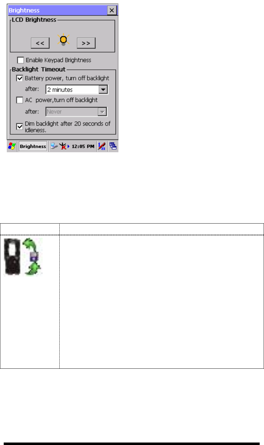
3-30
Figure 3-37 Brightness
3.2.5.3 Backup Restore
Table 3-25 Backup Restore
ICON ITEM & FUNCTION
1. You can backup/restore system to/from flash disk or inserted
memory card. (A. Disk on Chip, B. CF Card, C. SD Card)
( Figure 3-38)
2.
When you launch this AP, it must check backup file in DOC
first. And if you select other storage, it will check again.
3. Then if it has the file, appeared its date behind “Last backup
date:”; if not, disable “Restore Now” Button.
4. When you press the Backup/Restore Button will be a warning
dialog pop up. ( Figure 3-39)
5. When system backup/restoring finished will be a message
dialog will pop up. (A. Backup: Figure 3-40, B. Restore: Figure
3-41)
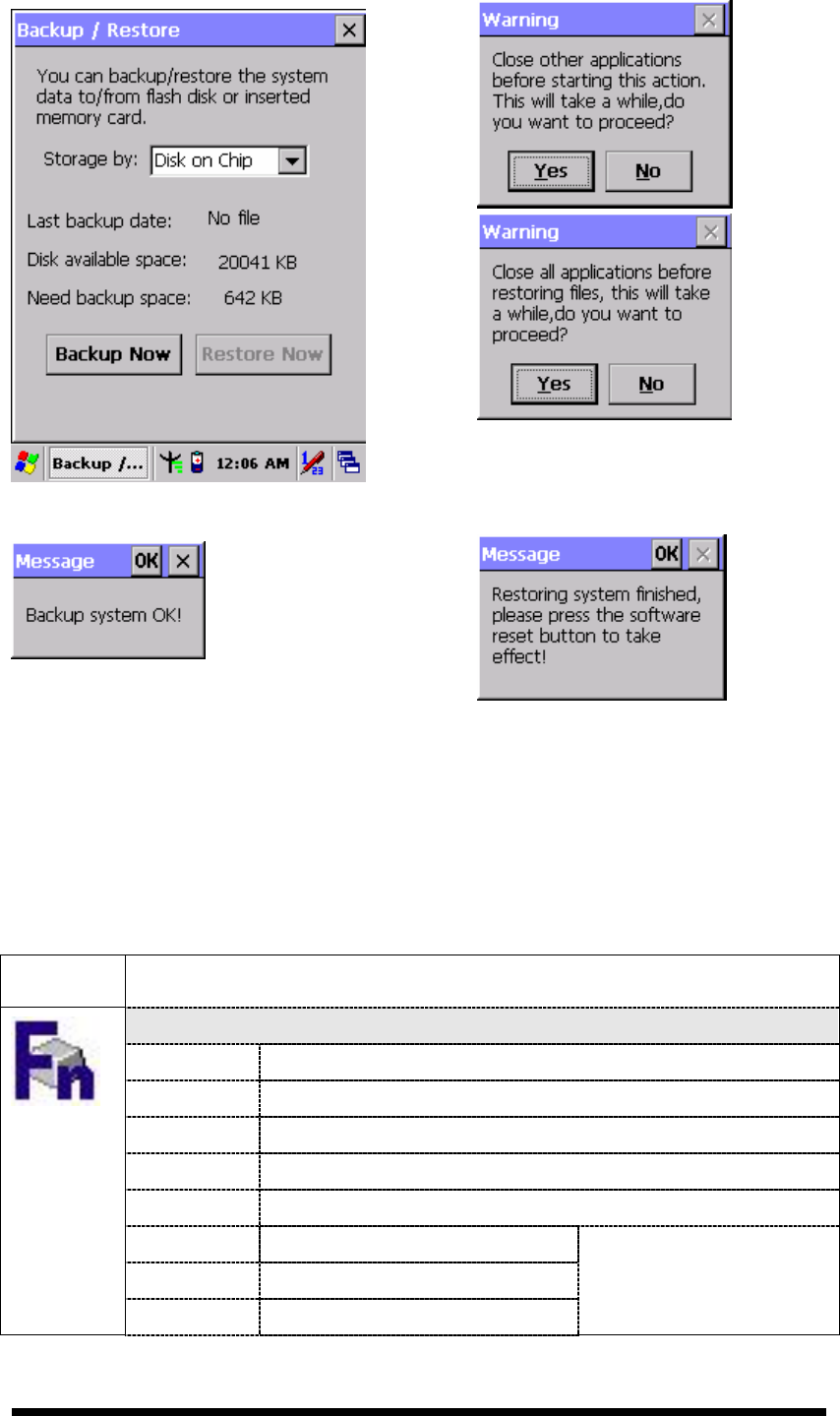
3-31
Figure 3-38 Backup Restore
Figure 3-39 Backup & Restore Start
Figure 3-40 Backup OK
Figure 3-41 Restore OK
3.2.5.4 Fn-key Settings
Table 3-26 Fn-Key
ICON
ITEM & FUNCTION
Fn-Key Setting (Figure 3-42)
Fn Key The Application Program of default setting
F1 Internet Explorer
F2 Microsoft WordPad
F3 Inbox
F4 My Computer
F5 Barcode Settings
F6 Media Player
F7 Calculator
Only for SC620
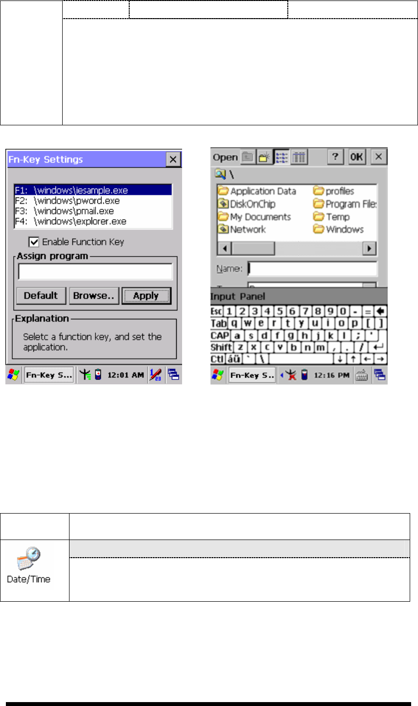
3-32
F8 Information
To assign your favorite application program to Hot Keys.
Choose one of Hot Keys from pull-down list.(Figure 3-43)
To tap “Browse…” inside “Assign program” applet.
Select one application program you want from program list, then,
choose “OK”. (Figure 3-43)
To tap “Default” to return back to default setting. (Figure 3-42)
Figure 3-42 Fn-Key Settings Figure 3-43 Fn-Key Settings
3.2.6 Date/Time
Table 3-27 Date/Time
ICON
ITEM & FUNCTION
“Date/Time” Tab :( Figure 2-14)
Please see the detail information of 2.5.1 Setting Time and
Date on P.2-21

3-33
3.2.7 Dialing Properties
Table 3-28 Dialing properties
ICON
ITEM & FUNCTION
“Dialing Properties” Tab :( Figure 3-44)
In the When dialing from list, select the “Location” where you
want to change settings.(Figure 3-45)
To create a new location, select “New”. Enter the name of the
location, and then select “OK”.(Figure 3-46)
Enter or edit the area code and local country code as needed.
In Dial using, select “Tone dialing” or “Pulse dialing”. Most
phone lines are tone.
To automatically disable call waiting, select “□
□□
□ Disable call
waiting by dialing”, select the appropriate number sequence in
the list, or enter a new sequence.
Editing dialing patterns (Figure 3-47)
Using the codes listed in the topic; revise the dialing patterns as
needed.
Notes:
If you need to use character other than the ones listed here,
use manual dialing.
Hyphens and spaces in dialing strings are ignored.
Some modems may not respond to the following characters,
even though your device lets you add them to the dial
string.
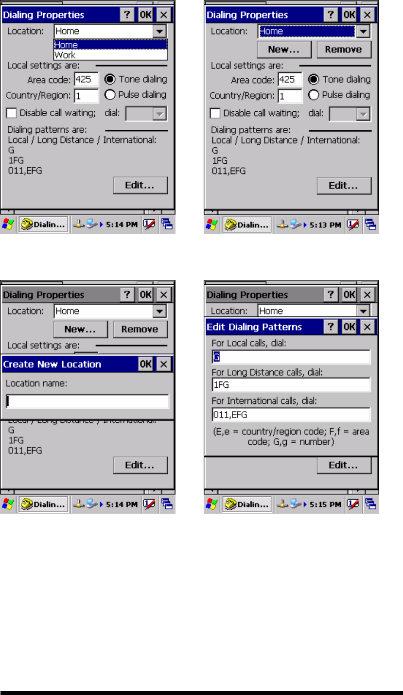
3-34
Figure 3-44 Dialing Properties Figure 3-45 Dialing Properties
Figure 3-46 Dialing Properties Figure 3-47 Dialing Properties

3-35
3.2.8 Display Properties
Table 3-29 Display properties
ICON
ITEM & FUNCTION
“Background” Tab :( Figure 3-48)
From the “Image” list, select an image you want as the
background of the desktop.(Figure 3-49)
To locate an image in another folder, select “Browse”.(Figure
3-50)
To have the image cover the entire background, select “ □
□□
□Tile
image on background”
“Appearance” Tab(Figure 3-51)
Change the color scheme :( Figure 3-52)
From the” Scheme” list, select a scheme.
View your choice in the preview box. If you like the scheme,
select “Apply”.
Create a custom color scheme:
From the “Item” list, select a display item.
From the “Basic colors” list, select a color, and select “OK”.
View your color selection(s) in the Preview box.
To save the scheme, select “Save”.
In the “Save this color scheme as” box, enter a name for the
scheme, and select “OK”.
Select “Apply”.
Figure 3-48 Display properties Figure 3-49 Display properties
3-36
Figure 3-50 Display properties Figure 3-51 Display properties
Figure 3-52 Display properties
3.2.9 Input Panel
Table 3-30 Display properties
ICON
ITEM & FUNCTION
“Input panel” Tab :( Figure 3-53)
Select the input method you want to change.
To change the Soft Keyboard Options , tap “Option” (Figure
3-54) .
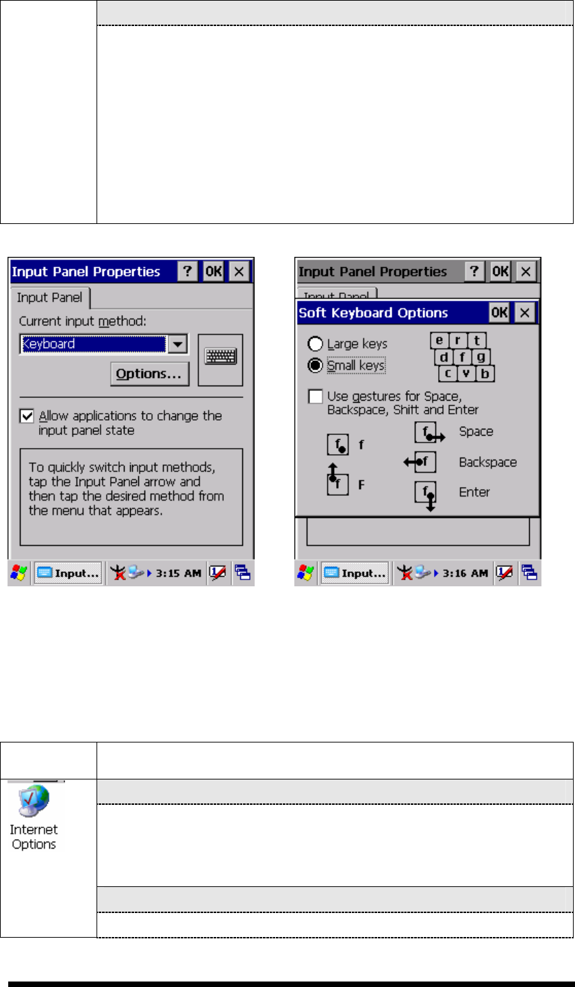
3-37
“Options” Tab :
Change the soft keyboard options as desired, selecting from:
Large or small keys
Using gestures for space, black-space shift, and enter.
To exit the soft keyboard Options, press “OK” on the control
bar, or press the <Enter> key on the keypad.
To exit the Input Panel, press “OK” on the control bar, or press
the <Enter> key on the keypad.
.
Figure 3-53 Input Panel Properties Figure 3-54 Input Panel Properties
3.2.10 Internet Options
Table 3-31 Internet Options
ICON
ITEM & FUNCTION
“General” Tab :( Figure 3-55)
Type in the URL of desired start page and the desired search
engine. You also change the Cache Size, clear the Cache and
Clear the History..
“Connection” Tab :( Figure 3-56)
Modify the network access setting as desired.
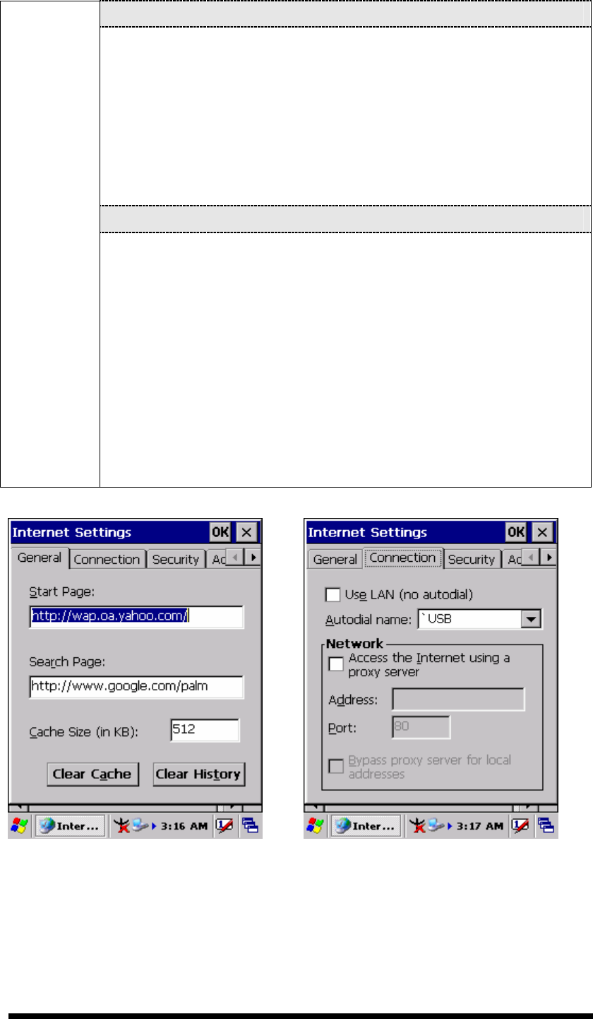
3-38
“Security” Tab (Figure 3-57)
Modify the security settings as desired. You can enable any of
the following by tapping the checkbox:
Allow cookies
Allow TLS 1.0 security
Allow SSL 2.0 security
Allow SSL 3.0 security
Warm when switching across secure and insecure areas.
“Advanced” Tab (Figure 3-58)
Modify the security settings as desired. You can enable any of
the following by tapping the checkbox:
Display Image in pages
Play sounds in pages
Enable scripting
Display a notification about every script error
Underline links-
○
Never
○
Always
○
Hover
Figure 3-55 Internet Settings Figure 3-56 Internet Settings