Shindaiwa Dgw310Dmc Users Manual MC Owner's
DGW310DMC to the manual 171e850c-4366-4b5d-b104-a7476eee1548
2015-01-05
: Shindaiwa Shindaiwa-Dgw310Dmc-Users-Manual-204088 shindaiwa-dgw310dmc-users-manual-204088 shindaiwa pdf
Open the PDF directly: View PDF ![]() .
.
Page Count: 42
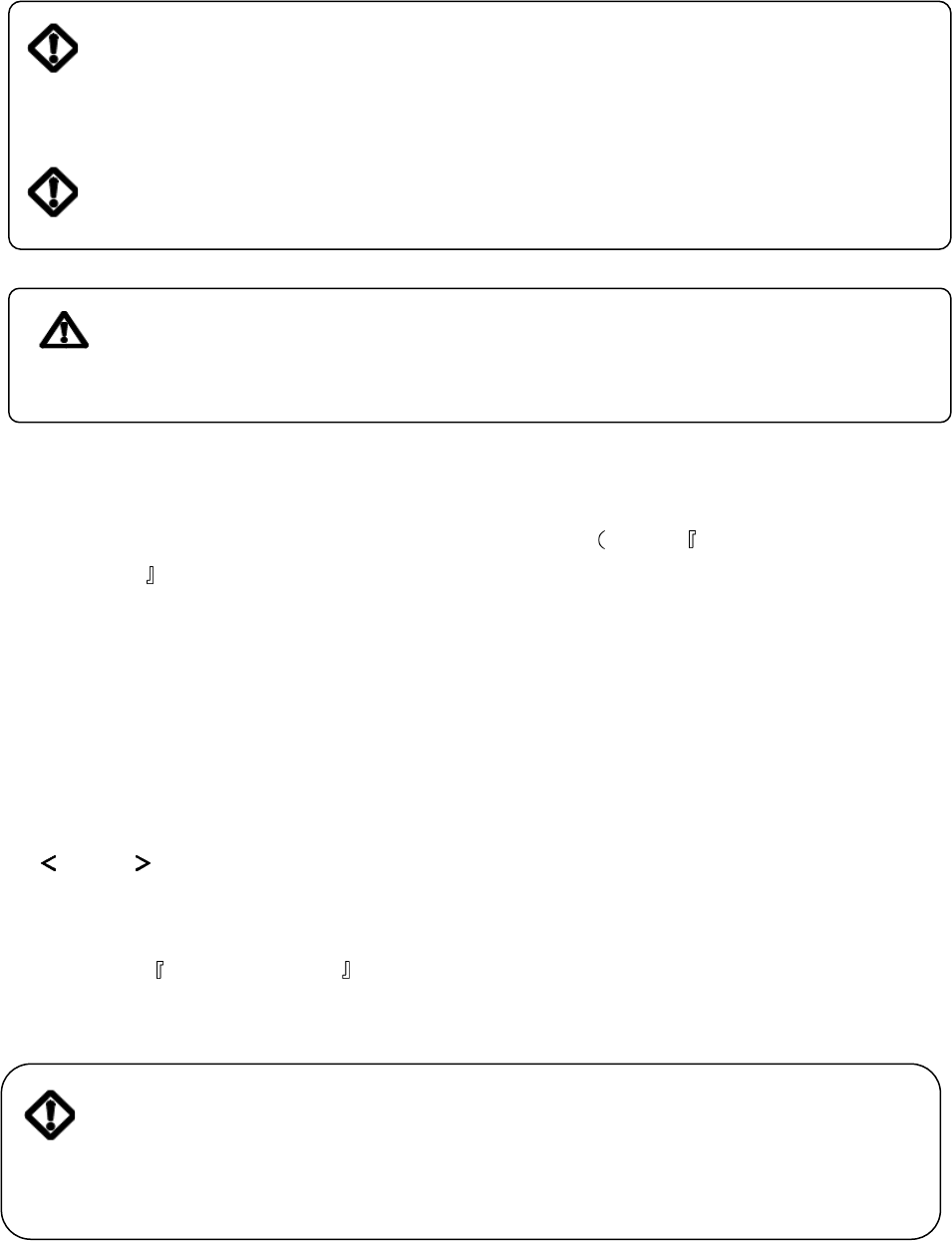
Caution
Do not operate the generator/
welder, or any other appliance,
before you have read and
understand the instructions for use
and keep near for readily use
OWNER’S MANUAL
GENERATOR / WELDER
DGW310DMC
DGW310MC
Sound Proof
Vertical, Water-Cooled
4-Cycle Diesel Engine
Table of Contents
1. Safety Guidelines ···················································2
2. Specifications ·························································6
3. Use ···········································································7
4. Parts ········································································7
5. Incorporated ···························································10
5-1 Eco Welding 10
5-2 Display 10
5-3 Frequency Change 10
5-4 Monitor Lamp 10
5-5 Remote Control (Option) 12
5-6 Earth Leakage Relay/Grounding 13
5-7 Slow-Down Feature 15
6. Initialization & Pre-check ·······································16
6-1 Checking Engine Oil 16
6-2 Checking Coolant/Water 17
6-3 Checking Fuel 18
6-4 Leakage Check for the above 18
6-5 Checking Battery 19
7. Operation ································································20
7-1 Start 20
7-2 Stop 22
8. Welding Operation ··················································22
8-1 Selection – Welding Cable 22
8-2 Polarity 23
8-3 Connection – Welding Cable 23
8-4 Welding 24
9 Generator Operation ·············································26
9.1 Output Range 26
9-2 Output Limitation 27
9-3 Operation 28
10 Simultaneous Use – Weld & Generate ··············30
11 Checking & Maintenance ····································31
12 Long-term Storage ··············································36
13 Trouble Shooting ················································37
14. Warranty Sheet (Type B) ········································39
CERTIFIED
1
Introduction
Thank you for purchasing Shindaiwa Sound Proof Diesel Engine Generator.
●This user manual was prepared to ensure the safe operation of this equipment. Therefore,
the m anufacturer of this equipm ent strongly recom mends that the user follow the
instructions herein, to avoid unnecessary accidents and repairs.
● Please operate this equipm ent after thoroughly reviewing and understanding the contents of
this manual.
● Please attach this manual, if the equipm ent will be sub-leased.
● Please store this manual near the equipment for easy reference.
● Following conversion will be used throughout the manual to indicate the degree of cautions.
Even som e of the items noted in Caution may lead to serious injuries.
Please read every item and follow all the safety guidelines.
Danger: Can cause serious injuries or death
Caution: Can cause minor injuries or damage to the equipment or other
properties.
Caution : Other types of caution

2
Danger: Suffocation from exhaust fume
● Exhaust fume from the engine contains many elements harmful to human.
Do not operate this equipment in poorly ventilated areas, such as inside a
room or in a tunnel.
Danger: Electric Shock
● Do not touch the output terminals during operation
● Do not insert metal objects (such as pin or wire) into receptacle
● Do not touch wires or electric parts inside the equipment during operation.
● Before connecting or disconnecting a load cable from output terminals, always turn the circuit
breaker to OFF position.
● Before connecting or disconnecting a load cable from output terminals, always turn the circuit
breaker to OFF position.
● Before connection or disconnection a welding cable from DC output terminal, stop the engine
and remove the engine key.
● Before performing any equipment check or maintenance, stop the engine and remove the
engine key. A maintenance person should always keep the key.
Danger: Burns
● Do not open the radiator cap while operating this equipment or immediately after stopping the
equipment, to avoid sustaining burns from hot vapor.
Danger: Injuries
● Close all doors and place locks during operating this equipment, to avoid injuries by
unintentional touching a cooling fan and fan belt.
Caution: Suffocation from exhaust fume
● Do not point the exhaust fume toward pedestrians or building.
Caution: Suffocation from exhaust fume
● Be sure to wear a fume proof mask in operation, because welding fume contains poisonous gas
and dust. Pay attention to the airflow direction and ventilation also in order to prevent from
inhaling the fume.
1. Safety Guidelines
1. Safety Guidelines1. Safety Guidelines
1. Safety Guidelines

3
Caution: Injuries to eye and skin
● Be sure to wear spark protection glass (es), long-sleeve shirts, gloves, etc. in order to protect
eyes and skin from harmful spark in welding.
● Battery fluid contains diluted sulfuric acid. Avoid contact with eyes skin or on clothing.
If the acid comes in contact, especially with eyes, flush water with a lot of water and contact a
physician immediately.
Caution: Electric Shock
● Do not flush water onto the equipment nor operate it in the rain.
Caution: Explosion
● Do not use the equipment or charge the battery, in the case the battery fluid level is lower than
the LOWER level.
● Battery may emit some combustible gas, so keep it away from fire and sparks.
Caution: Fire
●The equipment run on Diesel Oil. When refueling, always stop the engine and keep away from
fire. Moreover, always wait until the engine cools down before refueling.
● Always wire any drip of Diesel fuel or lubrication oil. Do not use this equipment when any leak is
found. Repair it before use.
●Temperatur e arou nd muffler and exhaus t can get extrem e l y hi g h. Ke ep an y
infl ammabl e item s (such as f uel, gas, paint, etc . ) away from th e equipment.
● Always operate this equipment on flat surface, at least 1 meter away from any objects (wall, box,
etc.)
● Always operate this equipment on flat surface and at least
1 meter away from any objects (wall, box, etc.)
● Do not connect AC output to any indoor wiring.
● A lways wait until t he equipm ent cools down , bef ore plac i ng an y cover ing
mater ial f or s torage.
4
Caution: Burns
● Do not touch the engine and muffler during operation and immediately after stopping the equipment,
for the temperature can reach extremely high.
● When checking engine oil or changing oil, always stop the engine, and wait until the engine cools
down. If you open either the oil gauge or the oil plug during operation, hot oil may cause some
injuries.
● Be sure to wear leather gloves, apron, shoe covers, eye protection glass (es) (mask), safety shoes,
and safety cap and long sleeve shirts, because welding splashes spatters.
Caution: Injuries
● When lifting the equipment, always use a lift hook. Do not lift the handle, for it may cause the
equipment to drop due to handle breaking off.
● When carrying the equipment by truck, fix it strongly to keep the equipment from sliding as roping
two points of handle.
● Always place the equipment on a flat and stable surface, to keep it from sliding. Be sure to lock the
wheels for with wheel type.
● When starting the engine, turn off the connected equipment
● And set the circuit breaker to OFF position.
● Do not move the equipment during operation.
● When performing equipment check and maintenance, always stop the engine.
● Do not operate the equipment if the equipment are modified or parts are removed
5
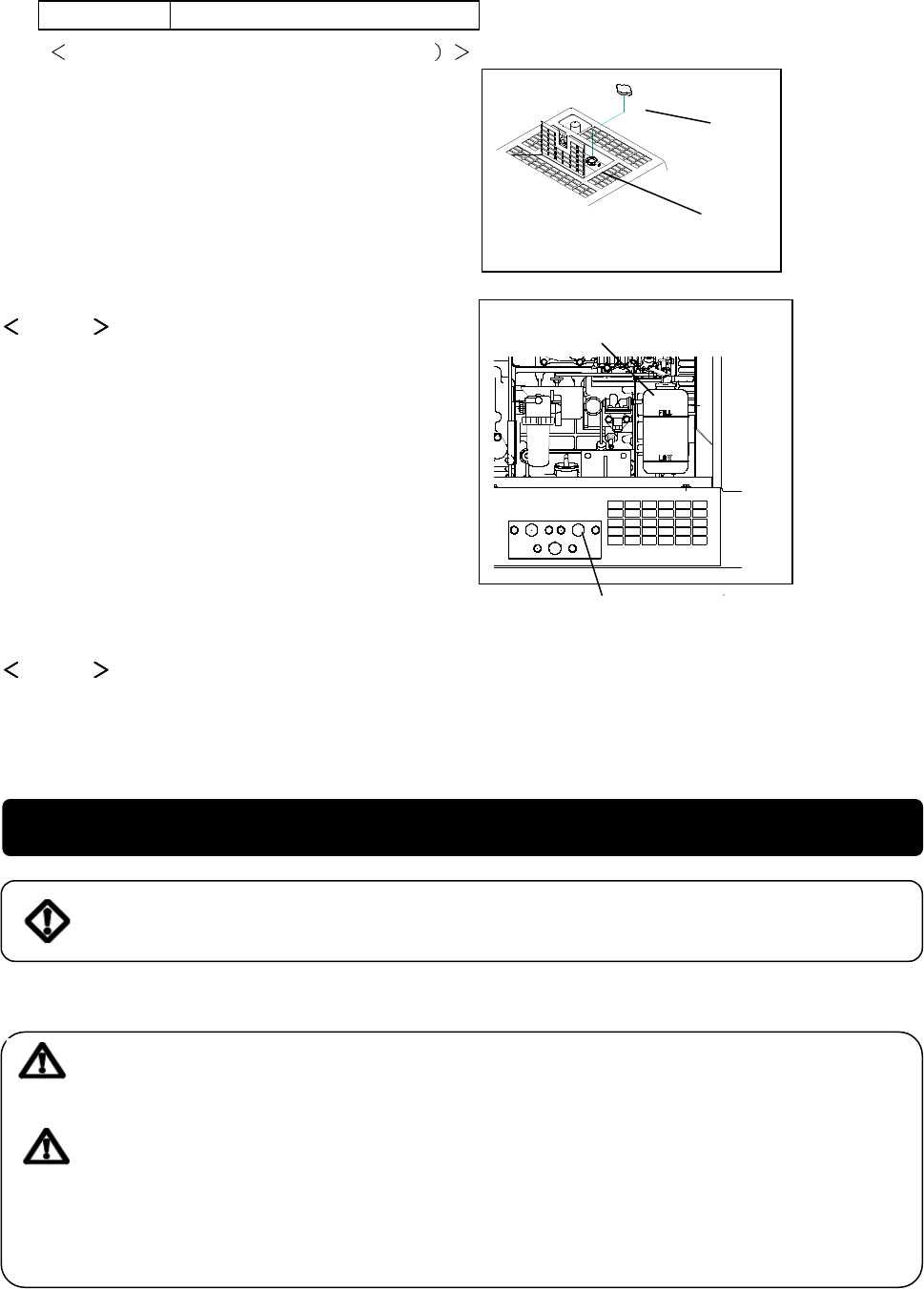
■Location of warning labels
When any warning label becomes unreadable or damaged, place a new label on the appropriate location.
When ordering a new label, use the following part number.
1. Suffocation from exhaust fume (No.19402-00106)
2. Suffocation from welding fume (No.19402-00107)
3. Electric Shock (No.19402-00102)
4. Electric Shock (No.19402-00103)
5. Injuries (No.19402-00109)
6. Burns (No.19402-00108)
7. Burns (No.19402-00112)
DGW310DMC
DGW310MC
1
1
2
6
4
3
7
5
5
2
3
5
4
6
5
5
7
6
Model DGW310DMC DGW310MC
Generating Method Rotating Field
Rated Current (A) 260 280
Rated Load Voltage (V) 30.4 31.2
Rated Duty Cycle (%) 100
Rated Speed min
-1
) 3000 3600
No Load Voltage (V) MAX 85
Adjustable Range (A) 30 160 30 160
Welding Rod (φ)
Eco
2.0 4.0
Eco
2.0 4.0
Adjustable Range (A) 70 280/85 310 35 280/45 310
Welding Rod (φ) Single
2.6 6.0
Normal
2.0 6.0
Adjustable Range (A) 35 150/45 160
Welding generator
Output
change
Welding Rod (φ) Dual
2.0 4.0
Rated Frequency (Hz) 50/60
Rated Speed min
-1
) 3000 3600
Phase 1-Phase 3-Phase
Rated Voltage (V) 100/110 200/220 200/220
Power Factor 1.0 0.8
Rated Output (kVA)
6
Receptacle1.5kVA×2 and
output terminal
8
(Output Total) 9.9
AC Generator
Rate Continuous
Model Kubota D722
Method Vertical In-lined Water Cooled 3 Cylinders Diesel Engine
Displacement (L) 0.719
Rated Output (kW{PS}/ min
-1
) 11.7{15.9}/3000 14.0{19.0}/3600
Fuel Diesel Fuel No.JIS2
Lubricant API Class CD or better
Lubricant Volume (L) 3.8(effective1.4)
Coolant Volume (L) 3.0(including sub tank 0.6)
Engine
Starting Method Starter Motor
Battery 46B24L
Fuel Tank Capacity (L) 37
Length (mm) 1410 (1280 Canopy Length)
Width (mm) 566
Dimension
Height (mm) 760 (870 with wheel)
Dry Weight (kg) 338 (348 w/wheel) 333 (343 w/wheel)
Full Weight (kg) 382 (392 w/wheel) 377 (387 w/wheel)
2. Specifications
7
● Arc Welding
● Electric Tools and Home Appliances
● Power Supply to lights
DGW310DMC
3. Use
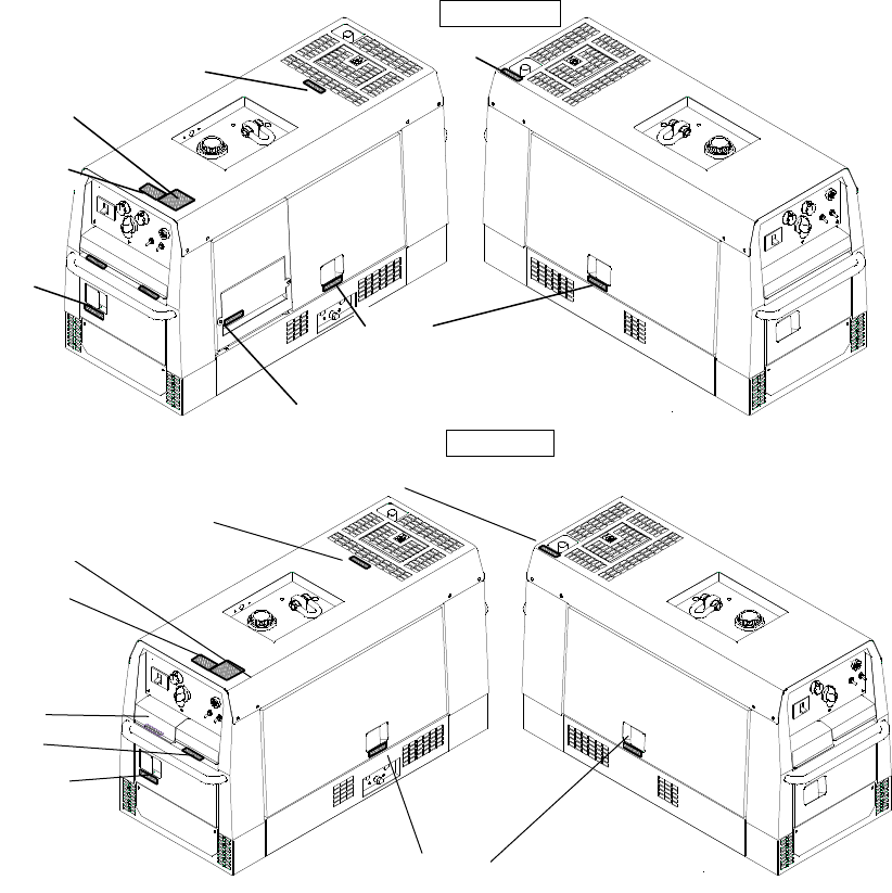
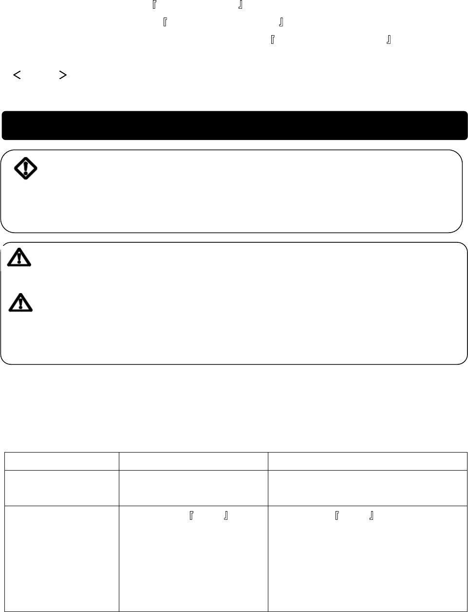
4. Parts
Caution Damage to the property and secondary damage
●Do not use other than the above purposes
●Never use it without consulting with medical equipment
manufacturer,
doctor, hospital and
obtaining confirmation in Hospital.
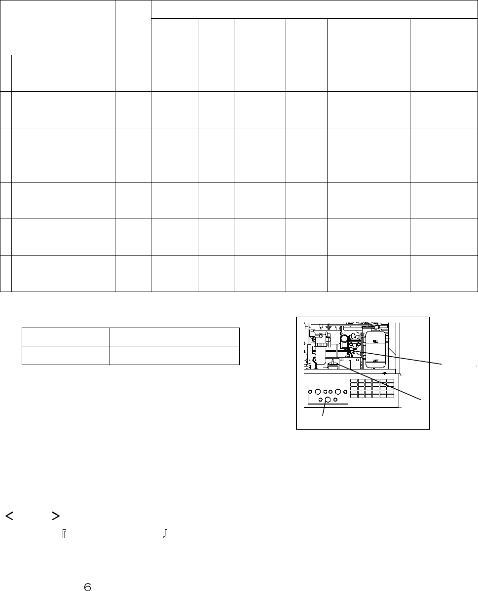
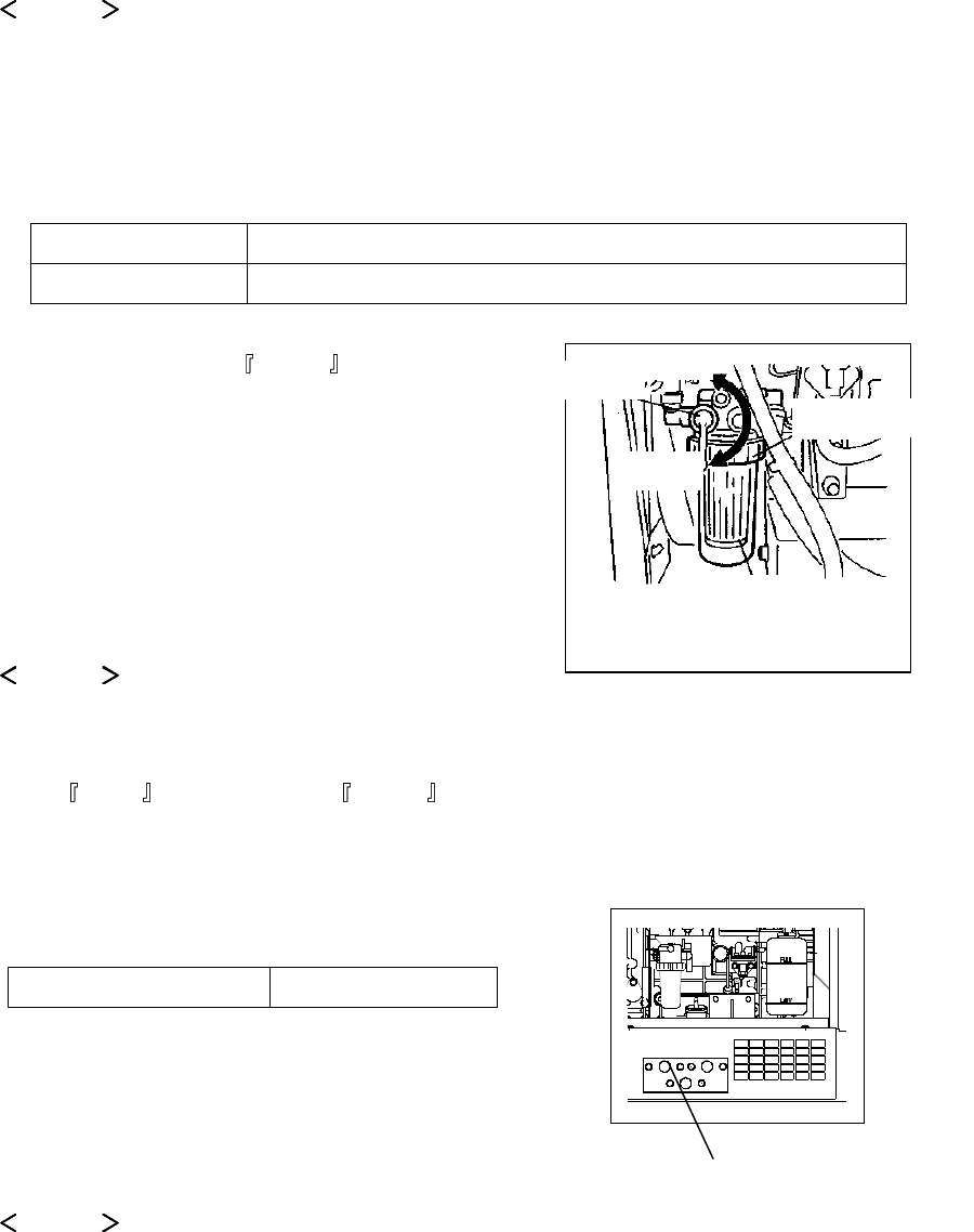
Breaker
Starter Switch
Output Change SW
Slow Down SW
Display Change SW
Display
Frequency Change SW
Welding Terminal B
Battery
Fuse
(Upper10A Lower 50A)
Welding Terminal A
Grounding Terminal
Front Door
Under Plate
8
DGW310MC
DGW310DMC
Breaker
Starter Switch
Output Change SW
Slow Down SW
D
isplay Change SW
Displ
a
y
Frequency Change SW
Welding Terminal
Battery
Fuse(Upper10A Lower 50A)
3P Output Terminal
Groun
ding Terminal
Front Door
Under Plate
ELCB grounding terminal
AC 3-P 200V out
AC 1-P 100V output
Fuel lever /Strainer
Fuel drain plug Oil drain plug
Air Cleaner
Sub tank
Oil gauge
Oil inlet
Water drain plug
9
DGW310MC
DGW310MC DGW310DMC
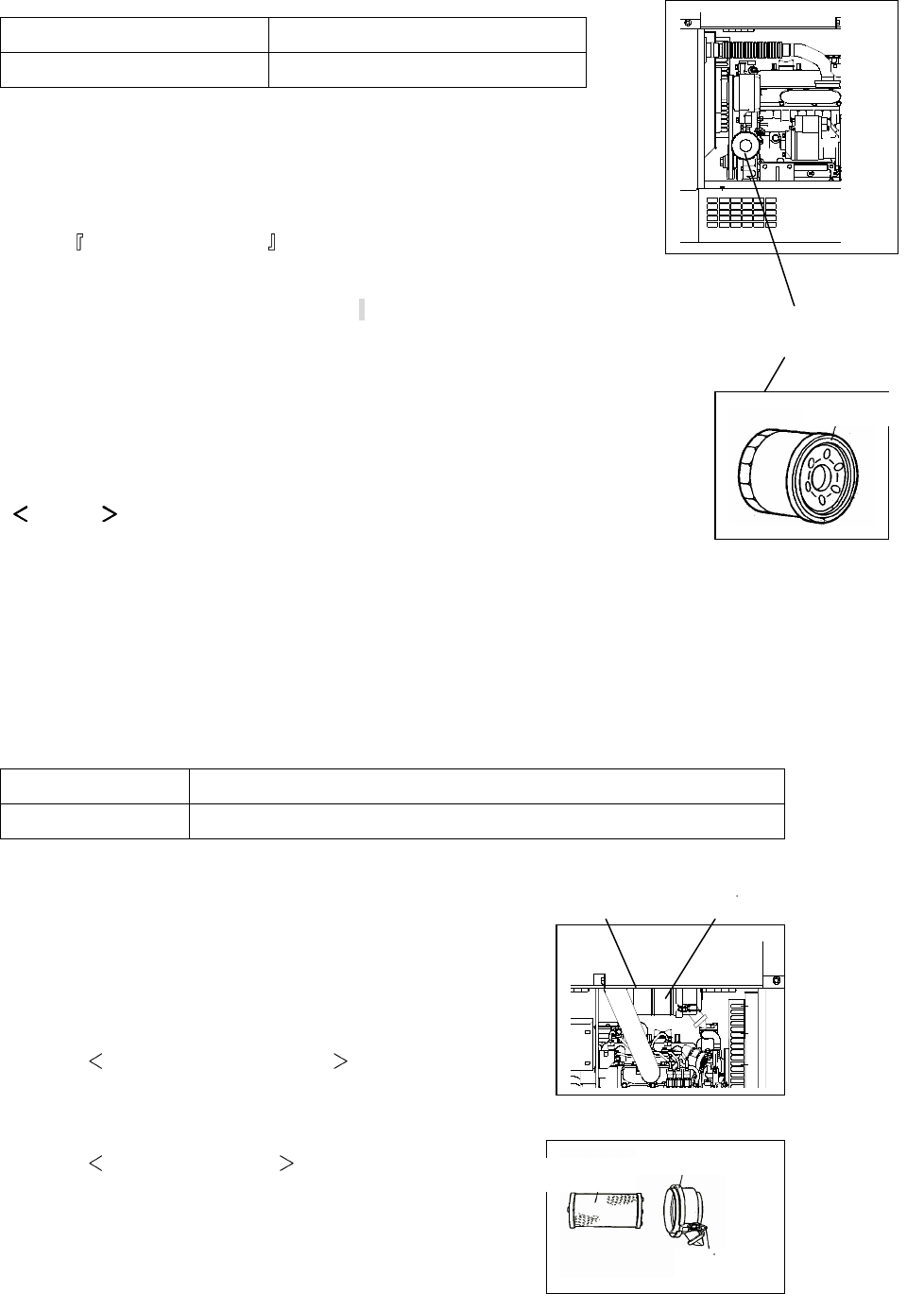
Air Cleaner
Sub tank
Oil gauge
Oil inlet
Water drain plug
Fuel lever /Strainer
Fuel drain plug Oil drain plug
Oil filter
Fuel inlet
Exhaust gas outlet
Lift hook
Handle
Handle
10
5-1. Eco Welding
The equipment is incorporated in Eco Welding Feature that is aiming at performing
The low noise, the lower fuel consumption and the low gas emission than those of conventional models.
When you turn the selector switch to Eco, you will be able to weld with Max 4.0mmφ rod at the slow
down speed.
Caution
●When welding is performed, do not turn the output selector switch which causes the burnout of the
switch
●Eco is designed for welding only. The breaker activates to TRIP, in case it is used for AC Output
5-2. Display
The equipment is incorporated in Digital Display. It displays Voltage , Hour , Speed successively,
by changing the display selector switch.
Caution
●During operation, voltage meter always displays the voltage in 200/220V, 3-Phase both at the
breaker position ON and OFF .
5-3. Frequency Selection
Selector either 50 or 60Hz by the selector switch on the front panel, in accordance with the load
frequency.
5-4. Monitor Lamp
The equipment incorporates monitor lamps as Water Temperature , Battery Charging and Oil
Pressure .
Under normal condition, when the starter switch is turned from STOP to REN , the lamps of, BATTERY
CHARGING and OIL Pressure turned To ON and all the lamps turn to OFF after the Engine starts.
When abnormality happens in running, monitor lamps flicker
And the engine stops automatically.
In the case the automatic shutdown is engaged, turn the starter switch to STOP once, and then restart
the engine. When the automatic shutdown is engaged again, check which lamp turns ON or OFF and
point out where the abnormality is.
5. Incorporated
Water Temp
Charge
Oil Pres
Preheat
11
Danger: Injuries
●
Close all the doors and place lock during operation, to avoid injuries by unintentional touch of cooling
fan or fan belt.
Danger: Burns
●Do not open the radiator cap while operating this equipment or immediately after
Caution: Burns
●Do not touch the engine and muffler during operation and immediately after stopping it, for
Danger: Injuries
●Close all the doors and place lock during operation, to avoid injuries by unintentional touch
of cooling fan or fan belt.
(1) Water Temperature Monitor Lamp
When the water temperature rises abnormally, the water temperature lamp flashes and the automatic
shutdown will be engaged.
When this happens, check water tank and replenish if needed. Refer to 6-2. Check the water
temperature
If the water level is normal, there may be possibility of overload. Always use the equipment within the
rated duty cycle and output power.
(2) Battery Charge Monitor Lamp
When the battery charge becomes unable during operation, the monitor lamp flashes and the automatic
shutdown is engaged.
Please consult with our authorized distributor or service section.
Caution
●The monitor cannot detect battery degradation or insufficient battery liquid.
Be sure to check battery liquid level periodically.
(Refer to 6-5. Battery Check )
(3) Oil Pressure Monitor Lamp
12
Caution: Burns
●Do not touch the engine and muffler during operation and immediately after stopping it, for the
temperature can reach extremely high
●When checking engine oil or changing oil, always stop the engine, and wait until the engine
cools down. If you open either the oil gauge or the oil plug during operation, hot oil may cause
some injuries.
When the oil pressure drops during operation, the monitor lamp flashes and the automatic shutdown is
engaged. When this occurs, check the engine oil level and replenish the maximum level if needed.
Caution
●The monitor cannot detect the degradation of engine oil. Please check engine oil periodically and replenish if
needed.
(Refer to 11. Checking and Maintenance )
●Check fuse next, when the abnormality other than Water Temp , Charge or Oil Pressure is detected.
If a fuse is burnet, consult with our authorized distributor or our service section, because there may be an
abnormality of electric/electronic parts or wiring and repairing may be required.
(Refer to 4. Parts )
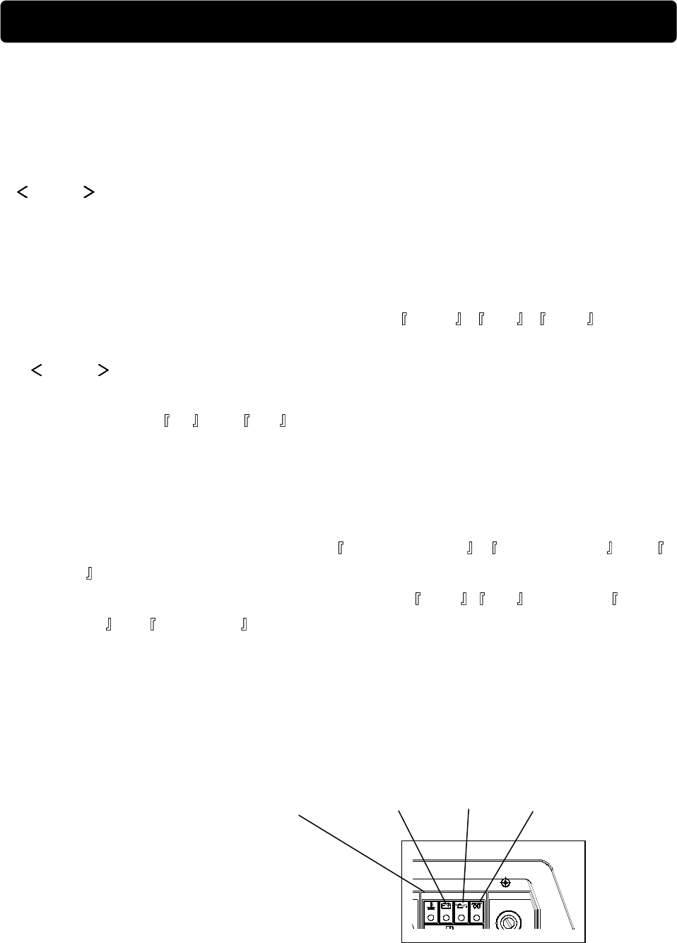
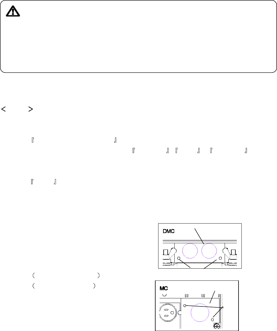
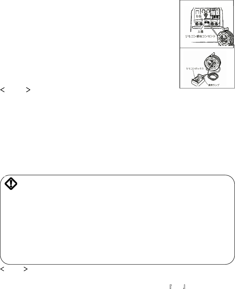
5-5. Remote Control Box (Option)
You can make remote control by connecting our remote control box
■How to connect remote control box
1. Remove the remote control
Receptacle cover.
DMC: M5 Screw x 2 pcs
MC: M4 Screw x 2 pcs
cover
screw
cover
screw
13
2 Insert the extension cord plug into
The receptacle.
In case of DGW310DMC, insert either A or B to be remote controlled.
3 Insert the plug into the receptacle of extension cord reel.
You can use 3 reels in series (30mx3)
Caution
●Never connect a remote control box plug to a receptacle of extension reel connected to AC100/110 Output
receptacle in the equipment. The abnormality lamp in the box turns ON to show abnormality when it is
connected by mistake.
●Never connect any device to a receptacle in the extension reel other than a remote controller.
●In case of using the cord reel incorporating ELCB set the ELCB ON and use.
5-6. ELCB and Grounding
Danger: Electric Shock
●Ground every grounding terminal to the earth as set in the manual. If even one of all is unconnected by
mistake or accident, it will make much more dangerous for human than the NO RELAY case, because
leaking current inevitably goes through the body.
●Even though all the terminals of the loads have been grounded to the earth, the bonnet grounding
thermal should be grounded to the earth.
●Grounding should be made after the engine stopped.
●Whenever the ELCB relay has activated, you should repair the leaking part always first of all.
Caution
●The ELCB activates only for AC output.
●ELCB activates when AC output is used with the output selector switch at ECO position for protection
load damage.
The circuit breaker is incorporated with ELCB to protect electric shock
The breaker trips when current leakage is detected due to insufficient insulation of loads
The specifications of ELCB are as follows.
●Rated Sensitive Current less than 30mA (Grounding Resistance less than 500Ω)
●Activation Time less than 0.1 second
14
(1) Grounding
A qualified electrician should perform the grounding work for the following 3 points. (Ground Resistance
less than 500Ω)
●The ELCB grounding terminal
●The bonnet grounding terminal
●The load bonnet terminal
Caution
●In the event you cannot ground, consult with our
authorized distributor or our service section.
(2) Operation Check
1. Turn a tarter switch from STOP to RUN .
2. Set the breaker lever to ON .
3. Push a test button in the breaker.
(The device is normal when ELCB Lamp (Red) turns ON and the lever positions at the middle of
ON and OFF ).
4. Push the reset button.
(The ELCB lamp (red) turns OFF)
5. Push down the breaker lever OFF .
6. Proceed with engine start procedure once returning a starter switch to STOP .
In the event you cannot complete all steps as above, the device is out of order. Consult with our
authorized distributor or our service section.
Reset Button Test Button
ELCB Lamp
ELCB Grounding terminal
Earth lod
Bonnet Grounding terminal
15
(3) The ELCB has activated
Caution: Electric Shock/Injuries
●Be sure to disconnect all the loads to the equipment when turning the breaker ON
again after ELCB has activated.
ELCB lamp (Red) turns ON and the breaker lever positions at the middle of and OFF .
In that case, reset the ELCB per the following procedure after having finished the leaked points.
1. Push the reset button.
2. Push the breaker lever down to OFF .
The above procedure brings restoration of the breaker lever to ON .
Caution
● In the case ELCB monitor lamps keep OFF on using, it means that
AC Output over supply or AC output Supply under output selector switch positions at ECO. Refer to 9-3.
Operation to recover.
5-7. Slow-down Feature
The Slow-down feature is to set the engine speed low automatically (in about 8seconds) for the purpose of
reducing noise and fuel consumption, whenever no welding operation or electric supply is performed.
In the case of using the Slow-Down feature, turn the slow-down switch to ON. By the condition, the engine
automatically moves to high speed, whenever welding operation or electric supply starts.
△ Caution: Damage to properties
●When using the load with magnet switch, turn the slow-down switch OFF .
Caution
● When the load less than 0.5A are connected to use, the slow-down feature does not function
sometimes. So, turn the switch OFF .
● When welding and AC supply are used alternately or intermittently, turn the switch OFF .
● When the output selector switch is at ECO ,the engine does not turn to high speed.
16
△ Caution: Fire/Burns/Injuries
● When checking engine, always stop the engine and keep away from hire.
Wait until the engine cools down before performing any check.
6-1. Engine Oil
When checking engine oil, be sure to
Keep the equipment leveled and insert
The oil gauge all the way in.
Before starting the equipment, make
Sure to fill the engine oil to the UPPER
Line through the oil inlet.
Caution
●If the equipment is not levels, you cannot obtain accurate oil level. Do not overfill (over UPPER line) the
engine oil. The excessive oil may damage the engine (inside cylinder).
■Selection of proper engine oil
Select the proper viscosity engine oil in compliance with ambient temperature. (Refer to the chart below)
Caution
●Use the API class CD or higher.
Viscosity and temperature
Temperature Over+20 +10 +20 -10 +40
Viscosity SAE30 SAE20 SAE10W/30
6. Initialization and Pre-check
Oil Drain Plug
Oil Plug
Oil Inlet
Oil Gage
17
6-2. Coolant and Water
Danger: Injuries
● Close all doors and locks during operating equipment to avoid injuries by accidental touch cooling fan or
fan belt.
Danger: Burns
● Do not open the radiator cap while operating the equipment or immediately after stopping the equipment to
avoid sustaining burn from hot vapor.
Caution: Burns
● Do not touch the engine or muffler during operation or immediately after stopping the equipment for
the temperature can reach extremely high.
Check to see if the coolant/water level is between FULL and LOW in the sub tank.
If it is below LOW level, fill he tank and the radiator accordingly.
(1) Filling the sub tank
1. Remove the sub tank cap.
2. Fill up the sub tank to FULL level.
3. Install the cap again.
(2) Filling the radiator
1. Open the top plate.
2. Remove the radiator cap.
3. Fill the radiator up to the top/
4. Install the cap again and tighten.
5. Close the top plate.
Caution
● Use Long Life Coolant to prevent from freeze and rust.
(30% mixture LLC is filled when shipped out from factory)
Cap
Sub Tank
Top Door
Radiator
Cap
Water Inlet
Sub tank
18
● Mixture ratio of the coolant should be 30%-45% depending on the ambient temperature.
● Replace LLC at every year or 2000 hours.
Recommended LLC concentration (for reference only)
Lowest Temp. -15 -20 -30
Mixture Ratio 30% 35% 45%
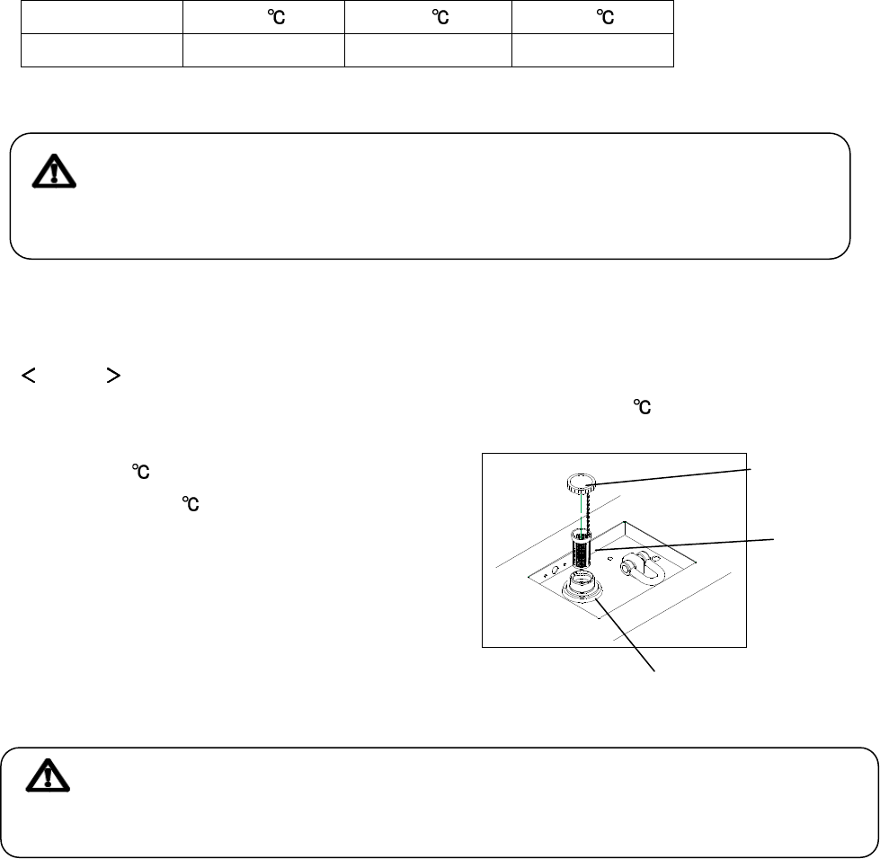
6-3 Fuel
Caution: Fire
●Always wipe any drip of fuel. Do not use the equipment when any leak is found.
Repair the equipment before use.
Check the fuel level and add the fuel if it is necessary.
Caution
●Use Diesel Fuel JIS No.2 in the event ambient temperature down to -5
●In colder area, use JIS No.3 (down
To -15
.)
or JIS No. Special 3
(down to -25 )
●Always use fuel strainer in the
fuel inlet.
●Fill the fuel tank slightly less
than the FULL tank.
6-4.Fuel, Engine Oil and Water Leakage
Caution: Fire
●Do not use the equipment when any leak is found. Repair the equipment before use.
Be sure to check any leakage for fuel, oil and coolant/water at the hose connections by opening the side
doors. Whenever checking leakage, turn the fuel lever OPEN and be sure to close the fuel lever after
checking.
Tank Cap
Strainer
Fuel Inlet
19
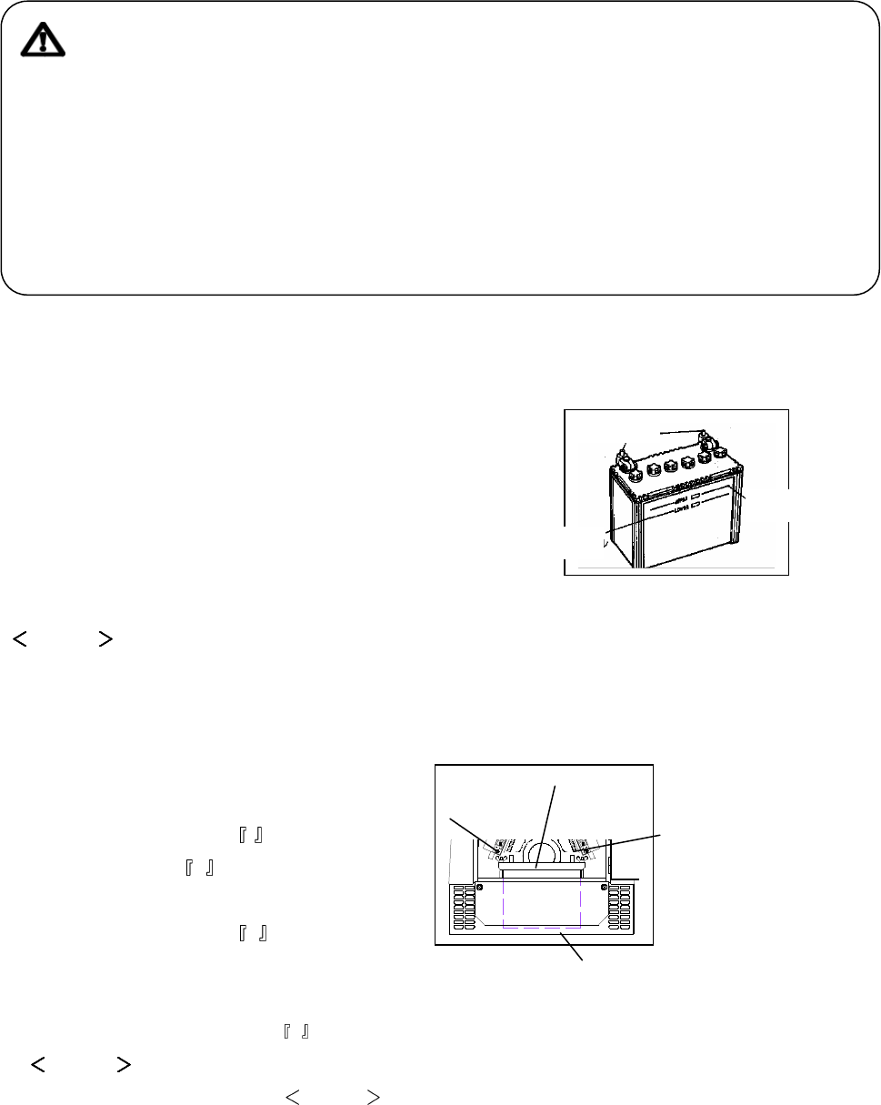
6-5 Battery
Caution: Injuries to eye and skin
● Battery Fluid contains diluted sulfuric acid. Avoid contact
with eyes, skin or clothing.
● If the acid comes to contact, especially with eyes, flush with a lot of water and contact to a doctor
immediately.
Caution: Explosion
● Do not use the equipment or charge the battery in the case battery
Fluid level is lower than the LOWER level.
● Battery emits some combustible gas, so keep it away from fire and spark.
1. Check the fluid level. If the level is near or
lower than the LOWER level, add distilled
water until the fluid level reaches UPPER.
2 Make sure that the battery cables are firmly
secured to the posts.
Tighten the clamps if it is necessary.
Caution
● Check the hydrometer of the battery fluid. If it falls below 1.23, the battery requires recharging. Consult
with our authorized distributor or our service department.
■Replacing battery
1. Remove the under plate.
(M6 bolt x 2)
2. Remove the cable on - side.
(Always on + side first)
3. Remove the battery fixing plate.
4. Remove the cable on + side.
5. Remove the battery.
Reinstall a new battery in the reverse order.
(Install always the cable to the + positive post first in a new battery.
Caution
● Use the following battery. 46B24L
● When replacing a battery, remove the under plate firstly. Otherwise the battery slanted and the fluid
may leak and contact to eye or skin.
Ins Cap
+ terminal
Terminal
Fix Plate
Under Plate
Lower level
Upper level
Terminal
20
Danger: Suffocation from exhaust fume
●Exhaust fume from engine contains many elements harmful to human. Do not operate this
equipment in poorly ventilated area such as inside room or in tunnel
Caution: Suffocation from exhaust fume
●
Do not point the exhaust fume toward pedestrians or building.
Caution: Fire
●Temperature around muffler and exhaust can get extremely high. Keep any inflammable items
(such as fuel, gas, paint, etc.) away from the equipment.
●Always operate this equipment on flat surface and at least 1 meter away from any objects (wall,
box, etc.)
Caution: Injuries
●Always place the equipment on flat and stable surface to keep the equipment from sliding and lock
wheels if they have.
●Before starting, turn the load switch OFF and set the
Equipment breaker OFF .
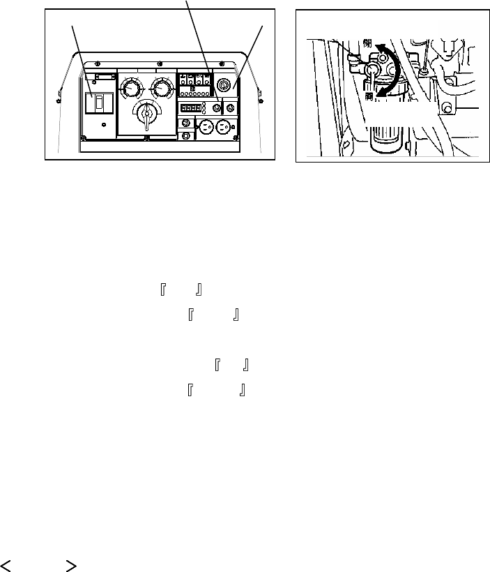
7-1. Starting
1. Turn the breakers to OFF .
2. Turn the fuel lever to OPEN .
3. Turn the Slow-Down Switch to ON .
4. When the temperature is below 5℃ turn and keep the starter Switch at PREHEAT until the preheat
lamp turns OFF (about 5 seconds).
5. Turn the starter switch to START . And then the engine starts by the starter motor.
CAUTION
● Do not drive the starter motor for more than 15 seconds successively.
● If you need to restart, wait for 30 seconds or more before retry.
6. Once the engine has started, release hand offs the starter switch.
Caution
● Once the engine has started, never turn the switch to START .
7. Operation
7. Operation7. Operation
7. Operation
21
7. Keep the engine idle for about 5 minutes.
■Restarting after stopping due to fuel shortage
This equipment is incorporated in automatic vacuuming air feature. Therefore, even though the engine
stops due to fuel run out, you can restart the engine easily by the following steps.
1. Turn the breakers to OFF
2. Turn the starter switch to STOP .
3. Fill the fuel.
4. Turn the slow-down switch to ON .
5. Turn the starter switch to START and drive the starter motor for about 10 seconds.
6. Release the starter switch, promptly as the engine started.
7. Wait for about 1 minute to vacuum the air out. The engine peed becomes stable when the air is
extracted.
Caution
● Never turn the engine NORMAL speed or connected the loads until the air is extracted completely (until
the engine becomes stable).
Breaker
Slow-down switch
Starter
Fuel lever Close
Open
22
7-2 Stopping
1. Turn the breaker to OFF .
2 .Turn the slow-down switch to ON .
3. Keep the engine (cool down) for about 5 minutes.
4. Turn the starter switch to STOP .
5. After the engine stops, turn the fuel lever to CLOSE .
Caution
● When the engine will not stop in spite of turning the starter switch to STOP, turn the fuel lever to CLOSE,
then the engine will stop in a few minutes. In this case, be sure to consult with our authorized distributor
or our service section and ask to repair.
8-1. Selection – Welding Cable
Select the cable in proper gauge, based on the allowable amperage and the length, per the table shown
below.
The welding capacity is to reduce if the small gauge or long cable is used.
Caution
● Welding cables should be used unstrained. When the welding cable are used in swirl, the welding
capacity is to reduce
Size of Cable Unit mm
2
Return
Length
20m 30m 40m 60m 80m 100m
Current
300A 30 38 50 80 100 125
250A 22 30 38 60 80 100
200A 22 30 30 50 60 80
150A 22 22 22 38 50 60
100A 22 22 22 30 30 38
8. Welding Operation
23
8-2. Polarity
There are 2 welding output terminals + and
-
.
Select the polarity according to the operation, referring to the table below.
Caution
●Welding Rods
Application Connection
- to Holder (Rod)
Normal General Welding such as
construction + to Earth (Material)
Thin Plate, Build-UP Welding
- to Earth (Material)
Reverse Stainless Steel + to Holder (Rod)
8-3. Connection – Welding Cable
Danger: Electric Shock
● Before connecting or disconnecting welding cable to terminal, stop the engine and
Remove the engine key. A person performing should always keep the key.
1. Stop the engine
2. Connect a cable to a crimping terminal, a rod holder and
a material holder.
3. As to DGW310DMC, connect the cable
referring the chart below.
ECO (Single) Single Dual
Rod
Φ2.0 φ4.0
Rod
Φ2.6 φ6.0
Rod
Φ2.0 φ4.0
Welding Output
Terminal A
Welding Output
Terminal A
Welding Output Terminal
A
&
Welding Output Terminal
B
Caution
●Be sure to crimp a crimping terminal to a cable and connect the cable to welding cable to welding
output terminal. Otherwise the terminal may burn out by the heat due to insufficient connections.
● Use a cable with a crimping terminal. To weld binding bare wires to an output terminal, the terminal
may burn out by the heat caused by insufficient connections and also bare wires may touch the
bonnet to bring short-circuit.
Rod Holder Cable
Crimping terminal
Holder
24
8-4. Welding
Caution: Suffocation from welding fume
● Be sure to wear a welding mask in operation, because welding fume contains poisonous
gas and dust. Pay full attention to the airflow and direction and sufficient ventilation also in
order to prevent from inhaling fume.
Caution: Injuries to eyes and skin
● Be sure to wear spark protection glass (refer to the table below), long-
sleeve shirts, gloves, etc. in order to protect eyes and skin from harmful
spark in welding.
Standard for Spark Protection Glass (Japan Industrial Standard)
No. 7 8 8 10 11 12 13
Current (A) 30 75 76 200 201 400
Caution: Fire
● Keep any inflammables and easily burning item away from the place in welding, because
welding splashes spatter.
Caution: Burn
●
Be sure to wear leather gloves, apron, shoe covers, eye protection glass, safety shoes, safety cap and
long-sleeve shirts, because welding splashes spatter.
Caution
●Never turn the output selector switch during welding, because
it must cause the burnout of the switch.
(1) DGW310DMC
The equipment can be operated 2 persons simultaneously.
Each person can adjust the welding current individually.
The current adjustable range by the dial changes at the output
selector switch position.
1 Turn the selector switch properly according to operation.
2 Adjust the voltage by the current adjustable dial. Refer to
the following chart next.
Current
Dial A
Current
Dial B
Selector
Switch
Termina
l
A
Termina
l
B
25
Welding Current
at the dial position (A)
Position
Freq
MIN
1 2 3 4 5 MAX
ECO
30 45 70 95 120
145
160
50Hz
70 90 135
175
215
260
280
1 Person Single 60Hz
85 110 155
200
245
290
310
50Hz
35 45 70 95 115
140
150
2 Persons Dual 60Hz
45 55 80 105
125
150
160
The values are for reference only. The length or the ambient temperature each affects the value.
When the remote control box is used, the value may change to some degree.
(2) DGW310MC
The current adjustable range by the dial changes at the output selector switch position.
1 Turn the selector switch properly according to operation.
2 Adjust the voltage by the current adjustable dial. Refer to
the following chart next.
Welding Current at the dial position (A)
Position Freq MIN
1 2 3 4 5 MAX
ECO 30 45
70 95 120
145
160
50Hz 35 60
110
160
205
255
280
Regular 60Hz 45 70
125
180
230
285
310
The values are for reference only. The length or the ambient temperature each affects the value.
When the remote control box is used, the value may change to some degree.
Current
Dial
Selector
Switch
Output
Terminal
26
9-1. Output Range
(1) 3-P 200/220V (3-P 4-Wires)
Maximum output from the terminals at 200/220
9.9kVA
(2)1-P 200/220V
1-P 200/220V is supplied by 1 pair out of 3 terminals.
Max. output by 1 pair is 6kVA and the maximum
output for 3 pairs total is 8kVA, which please note.
You should connect the load for 3 pairs evenly as
possible to terminals.
(3) 1-P 100/110V
1-P 100/110V is supplied by 2 receptacles and1-P
terminal set. Max 1.5kVA is supplied through 1
receptacle and max 3kVA is supplied from 1-P
terminal set.
Max output by 2 receptacles and
1 terminal set is 6kVA.
9. Genrating Operation
U
V
VV
V
W
O
UP to 9.9 kVA
U
UU
U
V W
O
Up to 6kVA Up to 6kVA
Up to 6kVA
Total 8kvA max
Total 6kVA
Receptac
le
Terminal
up
upup
up
to
toto
to
1.5kVA
1.5kVA1.5kVA
1.5kVA
Up
UpUp
Up
to
toto
to
1.5kVA
1.5kVA1.5kVA
1.5kVA
up
upup
up
to
toto
to
3kVA
3kVA3kVA
3kVA

27
9-2. Output Limitation
Please refer to the table below, because electric tools and home appliances cannot be judged only by the
rated.
The rated output or the power consumption due to the efficiency and character of components.
Applicable Load (For reference only)
Capacity(kW)
1-P 100/110V
1-P 200/220V
3-P 200/
220V
Loads
Receptacle
1pce
Terminal
1 set
Terminal
receptacle
total
Terminal
1 set
Total 3 terminal
set Terminal
Electric Bulb, Heater, etc.
1.5 3.0 6.0 6.0 8.0 ―
Electric Tools, etc. (Series
motor)
0.7 1.5 3.0 3.0 4.0 ―
Mercury Lamp (high power
factor type)
0.6 1.2 2.4 2.4 3.2 ―
Submersible Pump,
Compressor, etc. (induction
motor)
0.6 1.2 2.4 2.4 3.2 4.0
Series Motor Motor with brush
Induction Motor Brushless Motor
The value described is OUTPUT for induction motor load and
POWER CONSUMPTION for the other equipment.
Caution
● Be sure to use the frequency designated in the equipment incorporated in mercury
bulb or induction motor.
● The load incorporated in motor may require bigger power than the rated power
consumption.
So, consult with our authorized distributor or our engineering section to clarify.
● When connection to use 2 or more sets, start the load one by one, not to start them simultaneously.
● When starting a mercury bulb ON again, wait for about 15 minutes until it cools down.
28
9-3. Operation
Danger: Electric Shock
●Before connection or disconnecting a load cable from the receptacle, always turn the circuit breakers
(3-P and 1-P) to OFF. And stop engine and remove the engine key. A person to perform it should
always keep the key.
●Ground every grounding terminal to the earth as set in the manual.
If even one of all is unconnected, by mistake or accident, it must be much more dangerous for human
body than NO CONNECTION, because a leaking current inevitably goes through the body.
●Even though all the current leakage relays in the loads have been grounded to the earth, the
grounding terminal and the bonnet (canopy) should be grounded to the earth.
●Grounding should be made after the engine is stopped.
●Whenever the current leakage breaker activates, you should repair the leaking point first of all.
Caution: Injuries
●Be sure to connect to the output terminals or insert a plug to a receptacle, after confirming that all the
switches in the loads are positioned at OFF.
●Be sure to select the correct frequency, designated in the loads.
Caution: Damage to the property – Aftermath
●Whenever connecting to use medical equipment or appliances, be sure to consult
with the medical equipment company, doctor or hospital personnel.
●Be sure to select the correct frequency, designated in the loads.
Otherwise the loads may be damaged.
29
Caution
●The AC volt meter reads 3-P 200/200V apart from the circuit breakers position at ON or OFF
when the engine driving.
After the engine starts Refer to 7-1.Starting , operate as per the following procedures.
1 Turn the power switch off on the load.
2 Check and confirm the breakers position at OFF .
3 Select the correct frequency, designated in the loads.
4 Connect the loads to receptacle or terminals.
5 Close the terminal cover and fix it with the bolts.
6 Turn the breakers to ON .
■ Return -The circuit breaker has activated due to overload
Caution: Injuries
●Be sure to turn the power switch to OFF on the load when returning the circuit breaker to ON again,
when the circuit breaker has activated.
When the electric supply exceeds the rated output, the breaker activates to trip in order to shut down the
circuit. Check the breakers when the load stops operation.
ELCB lamp is to turn OFF in the case of overload shutdown. When the lamp keeps ON, refer to 5-6.
ELCB and Grounding .
When any breaker has activated, return the circuit breaker per the followings procedure.
1 Turn OFF all the power switches on the loads.
2 Once push down the breaker lever to OFF , push up the lever to ON .
Caution
●Take care for overload, referring to 9-2 Output Limitation
●The breaker activates when having used AC output in the selector switch at ECO position. In the
case stop using AC supply and return the breaker as above.
MC
DMC
Breaker
3
-
P/1
-
P 200/220V
Output Terminals
Rece
pta
c
l
e
1-P 100/110V
Output Terminals
Terminal
Cover
Breaker
Receptacle
1-P/3-P
200/220V
Output
Terminals
1-P 100/110V
Output Terminals
Output
Terminal
Cover
30
The circuit breakers react on the AC power supply circuit only. In the simultaneous use of welding and
generating, there may be happen overload to the engine. Refer to the following table and limit AC power use.
Limitation of AC Power Supply in the simultaneous use of welding and generating (60Hz)
DGW310DMC
Welding Output AC Power Output
Rod/Current Select 3-P Output (PF 0.8) 1-P Output
φ2.0mm/60A Dual 9.3kVA 7.4kVA
φ2.6mm/120A Dual 7.2kVA 5.7kVA
φ3.2mm/140A Dual 6.4kVA 5.1kVA
φ4.0mm/170A Dual 5.2kVA 4.1kVA
φ5.0mm/240A Single 2.0kVA 1.6kVA
φ6.0mm/300A Single 0kVA 0kVA
The 1-P figure shown is the total output of 1-P 100/110V and 200/220V.
DGW310MC
Welding Output AC Power Output
Rod/Current Select 3-P Output 1-P Output
φ2.0mm/60A Regular
9.3kVA 7.4kVA
φ2.6mm/120A Regular
7.2kVA 5.7kVA
φ3.2mm/140A Regular
6.4kVA 5.1kVA
φ4.0mm/170A Regular
5.2kVA 4.1kVA
φ5.0mm/240A Regular
2.0kVA 1.6kVA
φ6.0mm/300A Regular
0kVA 0kVA
The 1-P figure shown is the total output of 1-P 100/110V and 200/220V.
Caution
●Simultaneous use of Welding and AC Power is NOT available.
●Avoid simultaneous use in the case high welding quality is required.
10. Simultaneous use of Generating and Welding
31
Danger: Electric Shock/Injuries
●Before checking, stop the engine and remove the engine key which to be kept by the person to do.
●Do not open the doors during operation or just after, because the cooling fan or driving belts can enwind the
body.
Danger: Burns
●Never open a radiator cap during operation or just after operation, because of avoid
burns from hot vapor.
Caution: Fire/Burns
● Keep the equipment far away from fire.
● Do not touch the engine and muffler during operation or immediately after stopping the equipment, for the
temperature reaches extremely high.
Caution: Injuries to eyes and skin
● Battery fluid contains diluted sulfuric acid. Avoid contact with eyes, skin or on clothing.
● If the fluid comes in contact, especially with eyes, flush with a lot of Water and contact to a physician
immediately.
Caution: Explosion
● Do not use the equipment or charge the battery, in the case the
battery fluid level is lower than LOWER
level.
● Battery may emit some combustible gas, so keep it away from fire and sparks.
Caution
● Besides pre-check before operation, qualified person only should do check and maintenance.
● Our authorized distributor or our service section only should do the job marked ● in the table.
● Use the genuine parts only for replacement.
● Use the tray to receive when draining the waste fluids.
●
Be sure to comply with the regulations when discarding hazardous substances such as oil, fuel, coolant (LLC), filter,
battery, etc.
● To protect the environment, never discard the waste fluid to the grounds, the rivers, lakes, the oceans,
etc.
To optimize the use of the equipment, be sure to perform the check and maintenance based on the following
table. Use the hour meter on it as rough standard for operation time
11. Check and Maintenance

32
Check Time
Startup Every Every Every Every Every
Check Items
At 50 hrs
100 hrs 200 hrs 400 hrs 1000 hrs 2000 hrs
1
Check and supply fuel
○
Check and supply engine
2
oil
○
1st 2nd or after
3
Change engine oil
○ ○
1st 2nd or after
4
Change oil filter
○ ○
5
Check/Add water/coolant
○
○
6
Change Water/Coolant
Or 2 yrs
1st 2nd or after
7
Clean Fuel Strainer
○ ○
8
Change Fuel Filter Element
○
Drain Water/Clean Fuel
9
Tank
○
Check Leakage Fuel, Oil,
10
Water
○
11
Check Battery Fluid/Add Fluid
○
1st 2nd or after
12
Clean Air Element
○ ○
13
Change Air Filter Element
○
1st 2nd or after
14
Adjust V Belt Tension
● ●
●
15
Change V Belt
Or 2 yrs
33
Check Time
Every Every Every Every Every
Check Items Startup
At 50 hrs
100 hrs
200 hrs 400 hrs 1000 hrs 2000 hrs
Clean Radiator Fin
16
(Outer)
●
17
Clean Radiator (Inner)
●
Change Fuel Hose, Coolant
Hose, Oil Hose,
●
18
Anti
-Vibration Rubber
Or 2 yrs
Adjust/Plane Engine
● ●
19
Valve Clearance
Adjust Plane
20
Check/Adjust Injection Nozzle
●
Check/Adjust Injection
21
Nozzle
●
(1)Change Engine Oil
1
st
At 50 hrs
2
nd
or after Every 100 hrs
1 Remove the oil plug.
2 Remove the oil drain plug and
drain the oil completely.
3 Reinstall the oil drain plug tightly.
4 Checking the oil level by the oil level
gauge, replenish oil up to the UPPER level though the oil inlet.
(About 38 Liter)
5 Reinstall the oil plug tightly.
Caution
●Refer to 6-1. Check Engine Oil to decide Engine Oil.
●Change the packing to the new one in the oil drain plug whenever changing engine oil.
●Packing No.: C090―58961 (Kubota)
●After reinstalling the oil drain plug tightly, keep the engine drive for a while to check no engine oil leakage
and then stop the engine.
Oil Drain Plug
Oil Inlet Oil Gauge
Oil Gauge
34
2) Change Oil Filter
1st At 50 hrs
2
nd
or after Every 200 hrs
1 Drain the oil as described in
(1)Change Engine Oil .
2 Remove the oil filter using an oil filter wrench.
3 Smear a little engine oil on the rubber gasket of a new filter.
4 Screw the new filter into place and tighten it by
Hand until the gasket contact seat. Then give it
additional 1.1/4 turns using an oil filter wrench.
5 Supply engine oil.
Caution
●If an oil filter wrench is not available to get, contact our authorized
distributor or our service section to change.
●Oil Filter Part No.:15853-32433 (Kubota)
●After supplying engine oil, keep the engine drive for
a while to check no engine oil leakage and then stop the engine
(3) Clean/Change Air Element
Clean 1
st
at 50 hrs 2
nd
or after 100 hrs
Change Every 400 hrs
1 Loosen the wing bolts in the cleaner and
remove the air element.
2 Clean or replace the air element.
Dried contaminants adhere
Blow up compressed air from inside
the element.
Carbon or oil adhere
Replace to a new one.
3 Reinstall it in reverse order.
Air Cleaner
Clip
Gasket
Oil filter
Air element
Clip
Air Cleaner
cap
35
Caution
●Clean more frequently when it is used in dusty environment.
●Air Element Part No.: 1G347-11181 (Kubota)
(4) Clean/Change Fuel Strainer
Clean 1
st
at 50 hrs 2
nd
or after 200 hrs
Change Every 400 hrs
1 Turn the fuel lever to CLOSE .
2
Unscrew the retainer ring counterclockwise
And remove the cup and filter element.
3
Discard any dust or water inside the cup
and clean the filter by blowing compressed
air. (or replace element)
4 Reassemble it back.
Caution
●Be sure to check for any contaminants on the packing whenever reinstalling the cup.
●Be sure to confirm no fuel leakage by opening the fuel lever
to OPEN . Turn the lever to CLOSE finally after confirmation.
●Fuel Element Part No.: 16271-43561 (Kubota)
(5) Drain water in fuel tank
Drain At every 200 hrs
1 Unscrew the fuel drain plug.
2 Reinstall the drain plug after draining
water completely.
Caution
●
Change the packing whenever draining water
.
● Packing Part No.: 6C090―58961 (Kubota)
● Confirm no fuel leakage after reinstalling the fuel drain plug.
Fuel Drain P
lug
Retainer ring
Cup
Fuel lever
Close
Open
36
(6) Change Coolant/Water
Change At 2000 hrs or 2 yrs
Total capacity: 3L (including Sub Tank: 0.6L
1 Open the top door.
2 Remove the radiator cap.
3 Remove the water drain plug.
4 After draining all the water, reinstall
the water drain plug.
Caution
●Change the packing whenever changing
coolant/water.
●Packing Part No.: 6C090―58961 (Kubota)
5 Replace all the water in the sub tank.
6 Fill water to Max Level (to the water inlet)
7 Reinstall the radiator cap.
8 Close the top door.
Caution
●After supplying water, keep the engine drive for
a while to check no water leakage and then stop the engine
Danger: Electric Shock
●.
When performing check and maintenance, always stop the engine
Caution: Injuries
●When performing check and maintenance always stop the engine
△Caution: Fire/Burns
● Keep the equipment far away from fire.
● Do not touch the engine and muffler during operation or immediately after stopping the equipment for the
temperature reaches extremely high.
12. Long-Term Storage
Top Door
Radiator
Cap
Water Inlet
Sub Tank
Coolant Drain Plug
37
If the equipment will not be used for more than 2 months, perform the following maintenance and storage
procedure.
1 Remove the battery. (Refer to 6-5. Check Battery
2 Change the engine oil. (Refer to 11. Check & Maintenance
3 Drain the fuel from the fuel tank and the strainer. Refer to 11. Check & Maintenance
4 Clean all the parts, cover the equipment and keep in the clean and dry place.
Caution
● Recharge the removed battery once a month.
Danger: Electric Shock
●Do not operate the equipment if the equipment or you are wet.
●Before performing any equipment check or maintenance, stop the engine.
△ Caution: Injuries
●Before performing any equipment check or maintenance, stop the engine.
△Caution: Fire/Burns
●Keep the equipment far away form fire.
●Do not touch the engine and muffler during operation or immediately after
stopping the equipment for the temperature reaches extremely high.
Follow the guideline below when performing any troubleshooting. If you can
not resolve the problem by the troubleshooting guide, contact our authorized
distributor or our service section to request the repair.
Symptoms Presumable Causes Actions
1. Battery Weak 1. Recharge the Battery
Starter motor will not start 2. Battery Dead 2. Replace the battery
1. Fuel Lever at CLOSE 1. Fuel Lever to CLOSE
2. Insufficient Fuel 2. Replenish fuel
3. Water or contaminants 3. Drain water or Clean
in the fuel Fuel Tank & Strainer
The engine will not start
4. Fuse burnt 4. Repair
13. Troubleshooting

38
Symptoms Presumable Causes Actions
1. Insufficient Oil 1. Replenish Oil
2.
High Water Temperature,
2. Keep the rated
Insufficient Coolant/Water Replenish coolant/water
The engine starts but
stalls immediately
3. Unable to charge 3. Repair
Black or white smoke exhaust
from the muffler successively
1. Overload 1. Keep the rated output
1. Stop Solenoid Disorder
1. Turn the lever to CLOSE
The engine wont stop
to stop and repair
1. Output Selector Switch 1. Change to SINGLE
at ECO
or DUAL or REGULAR
2. Freq. Switch at 50Hz 2 Change to 60Hz
3. Current Dial Position
3. Turn it clockwise more
4. Poor Contact on Cables
4 Connect sufficiently
5. Improper Diameter or Length of Cable
5. Change the cable as per SELECTION – WELD
CABLES
6. Poor Contact to material
6. Connect securely
Welding Arc is weak
7. Simultaneous use 7. Stop using AC Output
1. Output Selector Switch
1 Change to ECO
at SINGLE or
REGULAR
or DUAL
Welding Arc is too
strong 2. Current Dial Position 2. Turn it counterclockwise more
1. Breaker at ON 1 Change to ON
NO AC Output 2.Selector Switch at ECO
2. Change to SINGLE , DUAL o
REGULAR
1. Wrong Frequency
1. Change to the load frequency
2. The rated current of load exceeds the rated
output of the equipment
2. Refer to OUTPUT LIMITATION
Weak AC Output
3. Simultaneous use Stop welding
1. Welding Cable short-circuit
1. Repair the short-circuit
Slow-down does not
activate
2 The power consumption
Of the load is 0.5A or below
2. Chang the slow-down
switch to OFF
1. Connected to AC100/110V receptacle by mistake
1. Connect to the remote control
receptacle
2. Connected AC100V load to remote control
receptacle
2. Disconnect the AC100V plug
Remote Control does
not work
3. The switch (breaker) on the cord reel at OFF
3 Change the switch to ON

39
Warranty Sheet
Type-B

2006.10
MEMO
Shindaiwa Corporation
Hiroshima Japan
