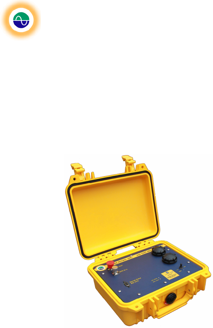
Shine Micro ST162 AIS receiver and transponder Portable Test Set User Manual DCM T162 UMX Rev1 0
Shine Micro, Inc. AIS receiver and transponder Portable Test Set DCM T162 UMX Rev1 0
Users Manual
Shine Micro, Inc
. AIS Test Set
ST162
© Copyright Shine Micro, Inc., 2011. All rights reserved.
DCM-T162-UMX Revision: 1.0 Page - 1 -of 43
Shine Micro, INC.
ST162 SERIES
AIS TEST SETS
USER MANUAL Rev 1.0
Shine Micro, Inc.
9405 Oak Bay Road
Port Ludlow, WA 98365
360-437-2503
www.shinemicro.com
Shine Micro, Inc
. AIS Test Set
ST162
© Copyright Shine Micro, Inc., 2011. All rights reserved.
DCM-T162-UMX Revision: 1.0 Page - 2 -of 43
Precautions
ELECTRICAL SHOCK HAZARD
Do not open the equipment.
Only qualified personnel should work inside the
equipment.
Immediately turn off the power if the equipment
is emitting smoke or fire.
Continued use of the equipment can cause fire or
electrical shock. Contact a Shine Micro agent for
service.
Do not disassemble or modify the equipment.
Fire, electrical shock or serious injury can result.
AVOID storing equipment in areas with
temperatures below –30°C (-22°F) or above
+70°C (158°F).
DO NOT place the test set where hot or cold air
blows directly on it.
Always remove any dirt or moisture before
closing the cover.
Avoid opening the battery compartments in the
rain. Allowing moisture into the battery
compartments can cause permanent damage to
the unit.

Shine Micro, Inc
. AIS Test Set
ST162
© Copyright Shine Micro, Inc., 2011. All rights reserved.
DCM-T162-UMX Revision: 1.0 Page - 3 -of 43
Table of Contents
Precautions ........................................................................................................................- 2 -
Table of Contents...............................................................................................................- 3 -
List of Figures.....................................................................................................................- 5 -
List of Tables......................................................................................................................- 6 -
1
Introduction..................................................................................................................- 7 -
1.1 Limited Warranty ...................................................................................................- 7 -
1.2 Return Goods Authorization Policy .......................................................................- 7 -
1.3 FCC Warning..........................................................................................................- 8 -
1.4 Industry Canada Warning.......................................................................................- 8 -
2
Product Description & Design Features ....................................................................- 10 -
3
Technical Specifications............................................................................................- 11 -
4.1 Unpacking and Inspecting Equipment.................................................................- 13 -
4.2
Required Equipment:.......................................................................................- 13 -
4.3
Optional Equipment: ........................................................................................- 13 -
5
Operational Overview................................................................................................- 14 -
5.1
VHF Antenna and Cable Considerations.........................................................- 14 -
5.2
GPS Antenna and Cable Considerations ........................................................- 14 -
5.3
Data Connections ............................................................................................- 14 -
5.4
Power-Up Test.................................................................................................- 14 -
5.5
Factory Default Messages...............................................................................- 15 -
6
Front Panel Indicators ...............................................................................................- 16 -
Appendix A - RS-232 Port................................................................................................- 18 -
Appendix B – Bluetooth Serial Port (Optional).................................................................- 19 -
Overview:...................................................................................................................- 19 -
Configuring Bluetooth Communication:.....................................................................- 19 -
Appendix C – ST162 Configuration Manager ..................................................................- 22 -
Test Set Customization .............................................................................................- 22 -
Use of ST162 Configuration Manager.......................................................................- 22 -
Tab: Load Configuration File...............................................................................- 23 -
Tab: GPS ............................................................................................................- 25 -
Tab: Test Set Static Data....................................................................................- 27 -
Set Name, Call Sign and Dimensions: .......................................................- 28 -
Set Ship Cargo, Destination and Arrival Time:...........................................- 28 -
Tab: Custom........................................................................................................- 29 -
Simulated Ships: ........................................................................................- 30 -

Shine Micro, Inc
. AIS Test Set
ST162
© Copyright Shine Micro, Inc., 2011. All rights reserved.
DCM-T162-UMX Revision: 1.0 Page - 4 -of 43
Safety Related Message (SRM):................................................................- 31 -
SART Message:..........................................................................................- 32 -
Tab: Reset...........................................................................................................- 34 -
Tab: Attenuation ..................................................................................................- 36 -
Tab: Serial Setting...............................................................................................- 37 -
Tab: Configuration File Editor .............................................................................- 38 -
Message List Editor: ...................................................................................- 39 -
Message Viewer and Editor:.......................................................................- 41 -
Appendix D - Troubleshooting..........................................................................................- 43 -
Unable to connect via Bluetooth:...............................................................................- 43 -
GPS LOCK LED Flashes:..........................................................................................- 43 -
New Batteries Installed but Test Set Won’t Power Up: .............................................- 43 -

Shine Micro, Inc
. AIS Test Set
ST162
© Copyright Shine Micro, Inc., 2011. All rights reserved.
DCM-T162-UMX Revision: 1.0 Page - 5 -of 43
List of Figures
Figure 1 - Front Panel ST162 ........................................................................................................- 16 -
Figure 2 - Control Panel..................................................................................................................- 19 -
Figure 3 - Add Bluetooth Device.....................................................................................................- 19 -
Figure 4 – Bluetooth Device Discovery...........................................................................................- 20 -
Figure 5 – Passkey Installation .......................................................................................................- 20 -
Figure 6 - Bluetooth Com Port Installation......................................................................................- 21 -
Figure 7 - Device Properties ...........................................................................................................- 21 -
Figure 8 - Bluetooth Com Port ........................................................................................................- 21 -
Figure 9 – ST162Configuration Manager Main Features ...............................................................- 23 -
Figure 10 – Load Configuration File Tab ........................................................................................- 24 -
Figure 11 - Open a Configuration File Dialog Box ..........................................................................- 24 -
Figure 12 – GPS Tab ......................................................................................................................- 25 -
Figure 13 – Error displayed without GPS lock ................................................................................- 26 -
Figure 14- Test Set Static Data Tab ...............................................................................................- 27 -
Figure 15 – Static Data Entry Screen .............................................................................................- 28 -
Figure 16 – Voyage Static Data Entry Screen ................................................................................- 28 -
Figure 17 – Custom Message Data Entry Tab................................................................................- 29 -
Figure 18 – Simulated Ships Data Entry.........................................................................................- 30 -
Figure 19 – Binary Message Data Entry Screen ............................................................................- 31 -
Figure 20 – Broadcast Safety Related Message Entry Screen ......................................................- 31 -
Figure 21 – AtoN Data Entry Screen ..............................................................................................- 32 -
Figure 22 – SART Message Entry Screen......................................................................................- 32 -
Figure 23 – Custom Message Load Button Enabled ......................................................................- 33 -
Figure 24 – Reset Tab ....................................................................................................................- 34 -
Figure 25 – Output Attenuation Tab................................................................................................- 36 -
Figure 26 - Serial Setting Tab........................................................................................................- 36 -
Figure 27 - Configuration File Editor ...............................................................................................- 38 -
Figure 28 - Message List View.......................................................................................................- 38 -
Figure 29 - The Message Viewer and Editor - Message 1 Example ..............................................- 42 -
Figure 30 - The Message Viewer and Editor - Message 5 Example ..............................................- 42 -

Shine Micro, Inc
. AIS Test Set
ST162
© Copyright Shine Micro, Inc., 2011. All rights reserved.
DCM-T162-UMX Revision: 1.0 Page - 6 -of 43
List of Tables
Table 1 - Default Targets.................................................................................................................- 15 -
Table 2 – DB9 Pin Connections ......................................................................................................- 18 -
Table 3 - Ship Type And Cargo.......................................................................................................- 30 -
Table 4 – Ship Type ........................................................................................................................- 30 -
Table 5 - ST162 Static Data Default ...............................................................................................- 35 -

Shine Micro, Inc
. AIS Test Set
ST162
© Copyright Shine Micro, Inc., 2011. All rights reserved.
DCM-T162-UMX Revision: 1.0 Page - 7 -of 43
1
Introduction
1.1 Limited Warranty
Shine Micro warrants its products to be free from defects for one full year from the date of purchase.
Shine Micro will, at its sole discretion, repair or replace any components that fail in normal use.
Labor and material costs for such repairs or replacement will be free of charge during the term of the
warranty. This warranty does not cover failures due to abuse, misuse, accidents, or unauthorized
alterations or repairs.
1.2 Return Goods Authorization Policy
To obtain warranty service, call Shine Micro, Inc. at 360-437-2503 for a Returned Goods
Authorization (RGA) number. The following RGA policy applies when returning units for repair or
replacement:
1. Prior to requesting an RGA, please contact our technical support department at 360-437-2503.
Our technicians may be able to remedy the situation without requiring the unit to be returned. If
they are unable to resolve the issue, they will connect you to Customer Service to obtain an
RGA number.
2. The following is mandatory to be included in return shipments of RGA product(s):
a. RGA number
b. Proof of purchase (a clear copy of the original invoice)
Please do not include accessories (i.e. cables, manuals, etc.) in your RGA shipment.
Failure to provide the above requirements and/or not specify problem(s) of the returned
product(s) will result in delays to the repair/replacement of the product(s) being returned.
Items returned without an RGA will be held in the receiving department until an RGA is
completed.
3. All RGA shipments to Shine Micro must have the RGA # clearly marked on the label/box.
a. Collect shipments will not be accepted.
b. Shine Micro is not responsible for any loss/damage in transit.
4. If the preceding points 1., 2., and 3. are not fulfilled, the Service Department will not be able to
process the RGA in a timely manner.
Notes:
1) A No Failure Found fee (NFF) will be assessed if a product is returned for repair and is found to
be working properly. The $75.00 NFF fee is subject to change without notice; please contact Shine
Micro for the current NFF fee.
2) All returned units found to be outside of warranty, whether due to an expiration of time period or
the warranty has been voided due to abuse, misuse, or otherwise unauthorized alteration, are
subject to a Diagnostic fee. The $155.00 Diagnostic fee is subject to change without notice; please
contact Shine Micro for the current Diagnostic fee.

Shine Micro, Inc
. AIS Test Set
ST162
© Copyright Shine Micro, Inc., 2011. All rights reserved.
DCM-T162-UMX Revision: 1.0 Page - 8 -of 43
5. Shine Micro, Inc. will return the repaired/replaced unit to the customer using ground service
unless a different shipment method is specified.
6. Shipping charges will be paid to Shine Micro by the customer unless a shipping account number
has been provided.
a. Payment of shipping charges is to be made by credit card unless a net 30 account has
been established.
b. Credit card payment processing information will be collected from the customer at the
time the RGA is issued.
7. All RGA product(s) will be repaired or replaced at the discretion of Shine Micro, Inc. within the
terms and limits of the warranty.
8. Improper shipment packaging, physical damage or alteration of product will void all warranties.
9. Under no circumstances will Shine Micro Inc. ship a replacement unit before the RGA unit is
returned to Shine Micro, Inc.
10. Always refer to your RGA number when making inquiries.
Shipping Address Billing Address
Shine Micro, Inc. Shine Micro, Inc.
9405 Oak Bay Road suite A PO Box 340
Port Ludlow, WA 98365 Port Gamble, WA 98364
Phone 1-360-437-2503
Fax 1-360-437-2483
Email info@shinemicro.com
Web www.shinemicro.com
Frequently Used Shipping Carriers
FedEx 1-800-GO-FEDEX www.fedex.com
UPS 1-800-PICK-UPS www.ups.com
USPS 1-800-ASK-USPS www.usps.com
DHL 1-800-CALL-DHL www.dhl.com

Shine Micro, Inc
. AIS Test Set
ST162
© Copyright Shine Micro, Inc., 2011. All rights reserved.
DCM-T162-UMX Revision: 1.0 Page - 9 -of 43
1.3 FCC Warning
WARNING: Changes or modifications to this unit not expressly approved by the party responsible for
compliance could void the user's authority to operate the equipment.
Note: This equipment has been tested and found to comply with the limits for a Class B digital
device, pursuant to Part 15 of the FCC Rules. These limits are designed to provide reasonable
protection against harmful interference in a residential installation. This equipment generates uses
and can radiate radio frequency energy and, if not installed and used in accordance with the
instructions, may cause harmful interference to radio communications. However, there is no
guarantee that interference will not occur in a particular installation. If this equipment does cause
harmful interference to radio or television reception, which can be determined by turning the
equipment off and on, the user is encouraged to try to correct the interference by one or more of the
following measures:
• Reorient or relocate the receiving antenna.
• Increase the separation between the equipment and receiver.
• Connect the equipment into an outlet on a circuit different from that to which the receiver is
connected.
• Consult the dealer or an experienced radio/TV technician for help.
1.4 Industry Canada Warning
This device complies with Industry Canada license-exempt RSS standard RSS-210. Operation is
subject to the following two conditions:
(1) this device may not cause interference, and (2) this device must accept any interference,
including interference that may cause undesired operation of the device.
Le présent appareil est conforme aux CNR d'Industrie Canada applicables aux appareils radio
exempts de licence. L'exploitation est autorisée aux deux conditions suivantes : (1) l'appareil ne doit
pas produire de brouillage, et (2) l'utilisateur de l'appareil doit accepter tout brouillage radioélectrique
subi, même si le brouillage est susceptible d'en compromettre le fonctionnement.
Shine Micro, Inc
. AIS Test Set
ST162
© Copyright Shine Micro, Inc., 2011. All rights reserved.
DCM-T162-UMX Revision: 1.0 Page - 10 -of 43
2
Product Description & Design Features
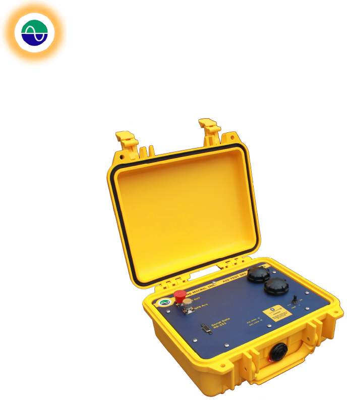
ST162 series AIS Test Sets can be used to test AIS installations, whether it’s AIS receivers in
aircraft, AIS base stations, or AIS transponders. The ST162 series is capable of performing pre-
mission checks, identifying malfunctioning systems, making on-channel noise measurements,
performing field and bench tests, and installation quality comparisons.
The ST162 series AIS Test Sets are portable – powered exclusively through two C-Cell batteries,
and feature a durable IP67 construction that protects the internal components against water, dust,
and UV radiation even when the lid is open. Other features include an internal AIS antenna and
GPS receiver.
Additional configuration options are available using the ST162 Configuration Manager. These
options include:
•
Program up to 100 custom messages
•
Easily customize any combination of up to 10 ships, 1 AIS Aid to Navigation (AtoN), 1
Safety Related Message (SRM), 1 binary message, and 1 SART
•
Program the Test Set’s static data and choose to use the current GPS position or its
internally set location
•
Vary the unit’s output power from −90 to −120 dBm at the EUT Port.

Shine Micro, Inc
. AIS Test Set
ST162
© Copyright Shine Micro, Inc., 2011. All rights reserved.
DCM-T162-UMX Revision: 1.0 Page - 11 -of 43
3
Technical Specifications
3.1 System Specifications
Designation: Portable AIS Test Set for AIS Receivers
Data interface: RS-232 at 115200 Baud (default)
or Bluetooth Serial Port Profile at 115200 Baud (optional)
Power Requirements: C Cell Batteries (X2)
Battery Life: 10 hours average
Temperature Range: −30 to +70°C (Storage), −15 to +55°C (Operation)
Compass Safe Distance: 1 Meter
3.2 Navigation Specification
12 Channel IEC 61108-1 Compliant GNSS Receiver
GPS ANT Port Impedance: 50 Ω
3.3 Dimensions and Weight
Length: 10.62 in.
Width: 9.68 in.
Height: 4.87 in.
Weight: < 7.5 lbs.
3.4 Mechanical
Housing Material: Polypropylene Copolymer
Material Finish: Yellow
Water Resistant: IP67
3.5 AIS Receiver Specifications
Number of Channels: 2
AIS1: 161.975 MHz
AIS2: 162.025 MHz
Channel BW: 25 KHz
AIS RX ANT Port Sensitivity: -107 dBm
Input Impedance: 50 Ω
EUT Port Input Power Level: 25 W (maximum)

Shine Micro, Inc
. AIS Test Set
ST162
© Copyright Shine Micro, Inc., 2011. All rights reserved.
DCM-T162-UMX Revision: 1.0 Page - 12 -of 43
3.6 AIS Signal Generator Specifications
Modulation Type: GMSK
AIS Data Rate: 9600 bits/s
Number of Channels: 1
Frequency: 161.975 MHz
Occupied BW: 25 KHz
Emission Type (ITU Class): 16KOFD
Signal Generator Output: Less than 150 µV/m @ 3 m
EUT Port Output: −120 to −90 dBm (programmable)
EUT Port Impedance: 50 Ω
Transmit Interval: 0 to 255 seconds (programmable)
Maximum Duty Cycle: 50%
Frequency Accuracy: +/− 2.5 ppm
3.7 Message Formats
Default messages:
Message 1: Scheduled Position Report for Class A mobile equipment
Message 5: Scheduled static and voyage related data
Other messages: Capable of simulating AIS messages 1, 2, 3, 5, 6, 8, 12, 14, 18, 19, 21,
24A and 24B
3.8 Connectors
RS-232: IP67 DB9 female
AIS EUT: Type N Jack
GPS Antenna: TNC Jack
3.9 LED Indicators
Power
Bluetooth Status
AIS Send
GPS Locked
Low Battery
AIS RX
3.10 Switches
OFF/ON Apply power to the unit
RX/RX+SEND/SEND: Switch between Receive only, receive and send AIS messages and
send only

Shine Micro, Inc
. AIS Test Set
ST162
© Copyright Shine Micro, Inc., 2011. All rights reserved.
DCM-T162-UMX Revision: 1.0 Page - 13 -of 43
4
Mechanical Installation
4.1 Unpacking and Inspecting Equipment
1. Inspect shipping box for visible damage such as crushing, puncture, or moisture. If
damage has occurred during shipping report it immediately to the shipping carrier and to
Shine Micro, Inc. including the tracking or other identifying number(s) of the shipment.
Contact information for Shine Micro, Inc. and the shipping carriers used by Shine Micro,
Inc. is included in the “Product Support Information” section of this manual.
2. Open the shipping box. If using a blade, take care to cut only as deeply as necessary to
open the box as items may have settled near to interior box surfaces during shipment.
3. Carefully remove all items from the shipping box. Thoroughly check all packing materials
for items that may have settled during shipment. Please recycle the shipping box and
packing materials.
4. Compare unpacked items to the packing list to ensure receipt of all ordered equipment.
Standard items include the ST162 and a CD (compact disk) containing this manual and
additional software.
5. Inspect equipment for visible signs of damage including
a. Scratches, dents, dirt, corrosion, moisture, or damaged fasteners on enclosure.
b. Any marring of enclosure, serial nameplate, or other inscriptions on the unit.
c. Any dirty, bent, or broken connector pins
If damage has occurred during shipping report it immediately to the shipping carrier and to Shine Micro,
Inc. including the tracking or other identifying number(s) of the shipment. Contact information for Shine
Micro, Inc. and the shipping carriers used by Shine Micro, Inc. is included in the “Product Support
Information” section of this manual. See Section 1.
4.2 Required Equipment:
• C Cell Batteries (X2)
4.3 Optional Equipment:
• Type N to X coaxial cable for EUT port (X denotes equipment under test connector)
• GPS Antenna
• AIS RX Antenna
• PC with RS-232 (or Optional Bluetooth)
• Standard RS-232 Cable with DB9 connectors
• USB to RS-232 Converter Cable

Shine Micro, Inc
. AIS Test Set
ST162
© Copyright Shine Micro, Inc., 2011. All rights reserved.
DCM-T162-UMX Revision: 1.0 Page - 14 -of 43
5 Operational Overview
5.1 VHF Antenna and Cable Considerations
The ST162 AIS Test Set has a VHF antenna built inside and is designed to test an AIS installation
without the need for an external antenna. In addition direct connection to an AIS system without an
antenna can also be performed by connecting directly to the AIS EUT port using coaxial cable with a
Male Type N connector. The direct connect output power can be varied from −90 to −120 dBm for AIS
receiver sensitivity testing. The attenuation can be set using the provided application, ST162
Configuration Manager. See Appendix C.
5.2 GPS Antenna and Cable Considerations
The ST162 AIS Test Set has an onboard GPS receiver for timing and position reporting. If an active
GPS antenna is used, it must be designed to operate with +3.3 VDC supplied on the coaxial feed line.
Connecting to a GPS antenna is optional. However, with a GPS signal, the unit will generate a position
report simulating a ship at the location of the Test Set. In addition, with a GPS signal, the unit can be
configured to store the current GPS location as the default message 1 location to be used when GPS is
unavailable.
5.3 Data Connections
The standard ST162 AIS Test Set may only be configured through the RS-232 port.
If the ST162 has the optional Bluetooth module installed it may be configured to take commands
from either the RS-232 port or the Bluetooth serial port. Data is always output on the RS-232 and
the default shipping configuration of the unit is with RS-232 set to the command port. Bluetooth
may be enabled using the provided application, ST162 Configuration Manager. The command to
change the communication port will not take effect until a restart or until the power is cycled on the
unit. The Bluetooth radio is only discoverable when the Bluetooth port is set to be the command
port.
The RS-232 port may be connected to the host computer using a standard DB9 RS-232 data
cable.
5.4 Power-Up Test
Power-Up Operation
Conditions: Place a C-Cell battery in each of the battery compartments with the + side toward the lid.
Optionally, connect a GPS antenna with a TNC male connector to the “GPS ANT” bulkhead connector.
Upon power up the “PWR” LED will illuminate, indicating that power has been supplied to the unit. Within
5 seconds the unit will boot and begin sending the configured messages. The “AIS SEND” LED will blink
with each AIS message sent. If a GPS antenna is connected, and with a good GPS signal, the “GPS
LOCK” LED will illuminate when GPS lock is acquired, typically within 45 seconds. The “GPS LOCK”
indicator illuminates at two intensities. The dimmer intensity indicates a weak GPS lock and the brighter
intensity indicates a strong lock.
Low Battery Indicator
To indicate a low battery condition the GPS LOCK LED will flash when the low battery condition is
reached. When the GPS LOCK LED begins flashing replace the batteries to ensure reliable operation.
Reset Procedure
Reset of the ST162 AIS Test Set may be accomplished in two ways:
Shine Micro, Inc
. AIS Test Set
ST162
© Copyright Shine Micro, Inc., 2011. All rights reserved.
DCM-T162-UMX Revision: 1.0 Page - 15 -of 43
1. Turn the power off and reapply power.
2. Connect to the command serial port (default RS-232). Using the ST162 Configuration Manager
open the com port. Verify that the unit’s serial number is displayed in the unit information
section. Open the “Reset” tab and click the “Restart” button. This will reset the unit without
returning it to factory default configuration. In order to completely reset a Test Set back to
factory default choose the “Reset to Factory Default” button. This will remove any static data
configured in the unit. To reset the messages back to the factory default configuration click the
“Restore Default Ships (1-5)” button.
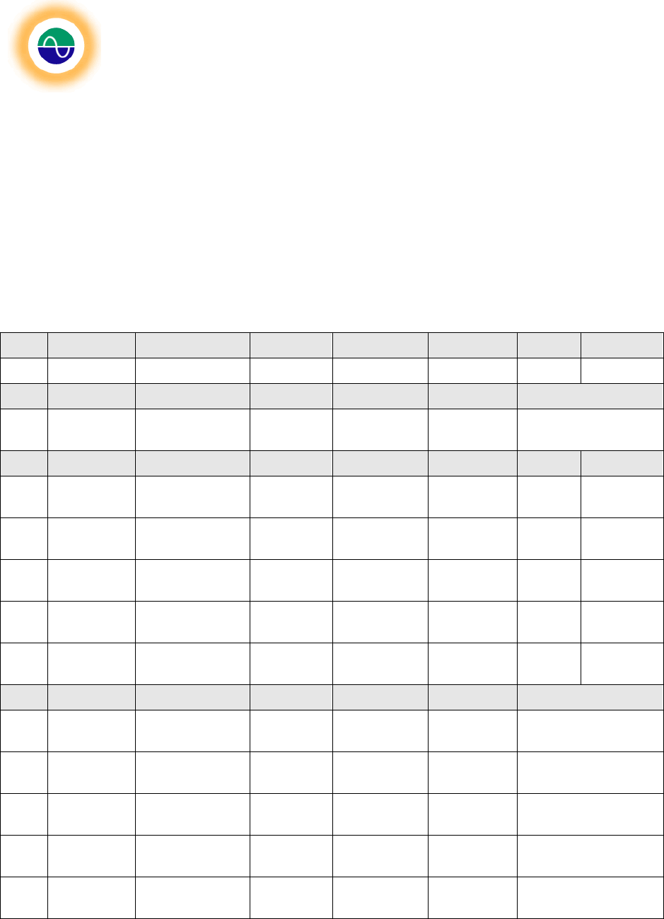
5.5 Factory Default Messages
The ST162 AIS Test Set is shipped preloaded with 10 messages and will simulate 5 ships. In addition,
the ST162 Test Set will generate a Message 1 and 5. The Shine Micro factory default messages are
displayed on the label on the inside cover of the Test Set and below:
Table 1 - Default Messages
MSG
MMSI ROT SOG Longitude Latitude COG Heading
1 338060087 -128 current current current current 511
MSG
MMSI Ship Name Call sign IMO # Type Destination
5 338060087 SHINE ST162
TEST SET @@@@
@@@ 0 0 TEST0 DEST
MSG
MMSI ROT SOG Longitude Latitude COG Heading
1 338060088 -128 102.3 050° 20.70’
E 26°
07.74’N 360.0 511
1 338060089 -128 102.3 138° 07.08’
E 35° 26.40’
N 360.0 511
1 338060091 -128 102.3 081° 31.48’
W 30° 07.69’
N 360.0 511
1 338060092 -128 102.3 122° 22.69’
W 48° 07.07’
N 360.0 511
1 338060093 -128 102.3 158° 01.75’
W 21° 11.15’
N 360.0 511
MSG
MMSI Ship Name Call sign IMO # Type Destination
5 338060088 SHINE ST162
TEST1 @@@@
@@@ 0 0 TEST1 MANAMA
5 338060089 SHINE ST162
TEST2 @@@@
@@@ 0 0 TEST2 ATSUGI
5 338060091 SHINE ST162
TEST3 @@@@
@@@ 0 0 TEST3 CECIL
5 338060092 SHINE ST162
TEST4 @@@@
@@@ 0 0 TEST4
COUPEVILLE
5 338060093 SHINE ST162
TEST5 @@@@
@@@ 0 0 TEST5 BARBERS
Shine Micro, Inc
. AIS Test Set
ST162
© Copyright Shine Micro, Inc., 2011. All rights reserved.
DCM-T162-UMX Revision: 1.0 Page - 16 -of 43
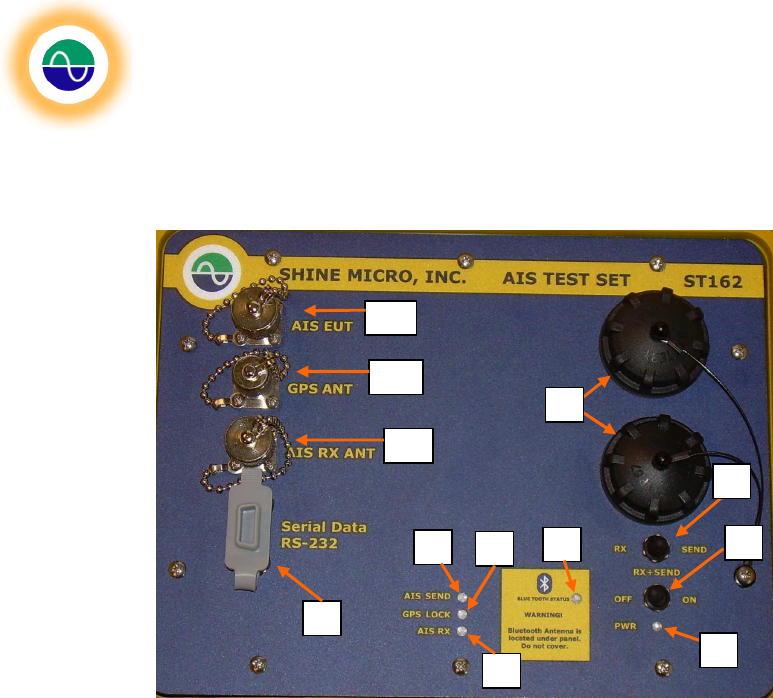
6 Front Panel Indicators
Figure 1 - Front Panel ST162
1. C Cell battery compartments. For the best results install only high quality Alkaline or NiMH
batteries. Take care to properly line up the threads on the cap and body of the compartments
before installing the cap.
2. RX/SEND switch: This is a three position switch where you may select “RX” (only receive
packets), “RX+SEND” (receive and send packets), or “SEND” (only send packets).
3. Power switch.
4. Power indicator. Illuminates when power is applied to the unit.
5. Bluetooth Status indicator: Illuminates when the Bluetooth is connected to a host. The
Bluetooth is not enabled by default and can not be connected remotely until the unit is
configured for Bluetooth control using the ST162 Configuration Manager. Note: The yellow
blocked area should be kept free from obstructions for optimal Bluetooth performance.
6. AIS SEND indicator: Illuminates with each AIS packet output.
7. GPS LOCK indicator: Illuminates at ½ intensity with a weak GPS lock and at full intensity with a
strong GPS lock. The GPS LOCK indicator is also used as a low battery indicator. When the
batteries are getting low the GPS LOCK led will flash.
8. AIS RX indicator: Illuminates upon receipt of an AIS packet.
9. Serial Data RS-232 port: This is the default communication port for the ST162. NOTE: When
the unit is configured for Bluetooth control the RS-232 port will still have data outputting.
However the unit will not respond to commands over the port.
10. GPS ANT connector: Connect a GPS antenna with a male TNC connector. A GPS Puck
antenna is included in the Quick Start Pack.
1
2
4
6
7
8
9
11
10
12
3
5

Shine Micro, Inc
. AIS Test Set
ST162
© Copyright Shine Micro, Inc., 2011. All rights reserved.
DCM-T162-UMX Revision: 1.0 Page - 17 -of 43
11. AIS EUT connector: Connect the AIS Equipment Under Test using a male Type N connector for
direct connection to AIS receivers and transponders. This is ideal for field or lab testing of
components or systems without an installed antenna.
12. AIS RX ANT connector: Connect an external receive antenna with a male Type N connector.
Caution!
This is a low-level input designed to receive “off-the-air” signals. Under no
circumstances connect a transmitter/transponder to this connector.
Shine Micro, Inc
. AIS Test Set
ST162
© Copyright Shine Micro, Inc., 2011. All rights reserved.
DCM-T162-UMX Revision: 1.0 Page - 18 -of 43
Appendix A - RS-232 Port
The Test Set’s default communication port is set as RS-232; baud rate 115200, data bits 8, parity none,
stop bits 1 and flow control none. The connector on the test set is a DB-9 female connector. A standard
RS-232 DB9 serial cable can be used to communicate with the Test Set. The minimum required
connections are listed in Table 2.
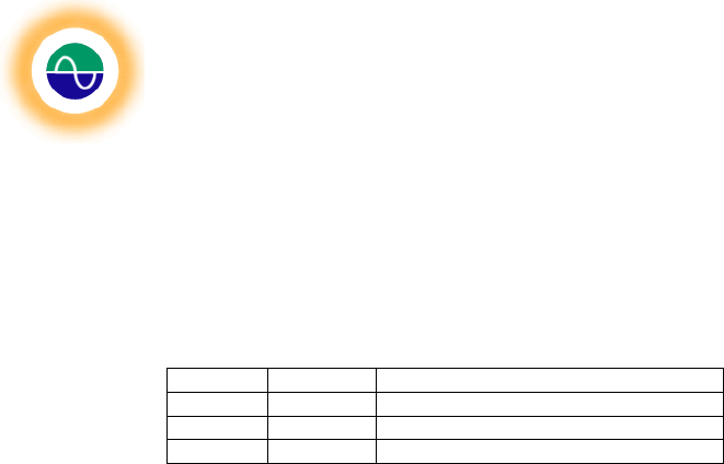
Table 2 – DB9 Pin Connections
*As related to the Test Set
DB-9 pin Function* Data direction
2 TXD Transmit data (test set → computer)
3 RXD Receive data (computer → test set)
5 GND Signal ground
Shine Micro, Inc
. AIS Test Set
ST162
© Copyright Shine Micro, Inc., 2011. All rights reserved.
DCM-T162-UMX Revision: 1.0 Page - 19 -of 43
Appendix B – Bluetooth Serial Port (Optional)
Overview:
This appendix will illustrate how to configure a Bluetooth enabled lap top to communicate with the
AIS Test Set.
Configuring Bluetooth Communication:
The ST162 can be configured to communicate over it’s RS-232 serial port or it’s Bluetooth serial port.
The default configuration is with RS-232 set as the default communication port, however using the
ST162 Configuration Manager the communication port can be switched to Bluetooth (Serial Setting Tab
in Appendix C). Once the Test Set is set to Bluetooth, the Test Set can be discovered and connected
through Window’s device manager.
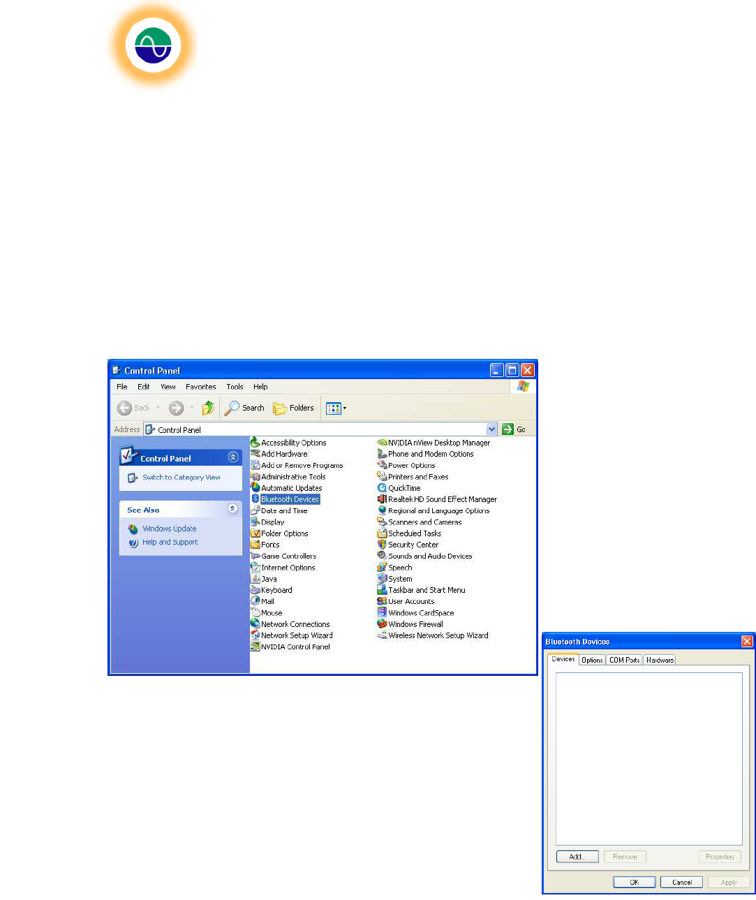
Open Control Panel. This can
be done on Windows XP by
clicking start and selecting the
Control Panel.
1. Open the Bluetooth Devices and click on the Add button.
Figure
2
-
Control Panel
Figure
3
-
Add Bluetooth Device
Shine Micro, Inc
. AIS Test Set
ST162
© Copyright Shine Micro, Inc., 2011. All rights reserved.
DCM-T162-UMX Revision: 1.0 Page - 20 -of 43
This will bring up the Add a Bluetooth Device
Wizard. Click on the checkbox indicating that “My
device is set up and ready to be found.” This will
enable the Next button.
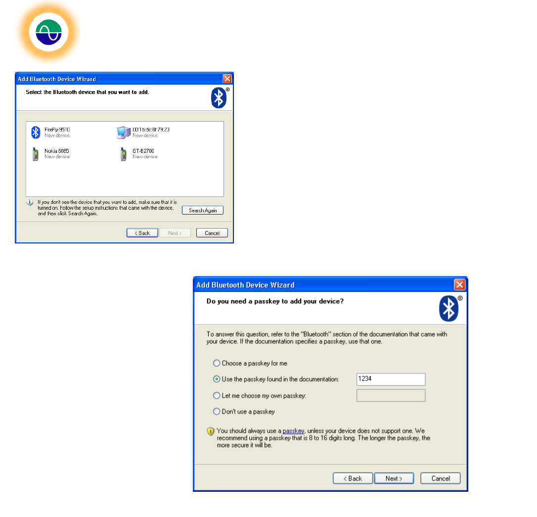
2. The wizard will search for available
Bluetooth devices. The ST162’s Bluetooth
radio is named “FireFly-XXXX” where XXXX
is a 4 digit code unique to each radio. For
this example the radio is named “FireFly-
951D”. Select the device and click next.
3. Select “Use the passkey
found in the documentation”.
Enter “1234” and click next.
Figure
4
–
Bluetooth Device Discovery
Figure
5
–
Passkey Inst
allation
Shine Micro, Inc
. AIS Test Set
ST162
© Copyright Shine Micro, Inc., 2011. All rights reserved.
DCM-T162-UMX Revision: 1.0 Page - 21 -of 43
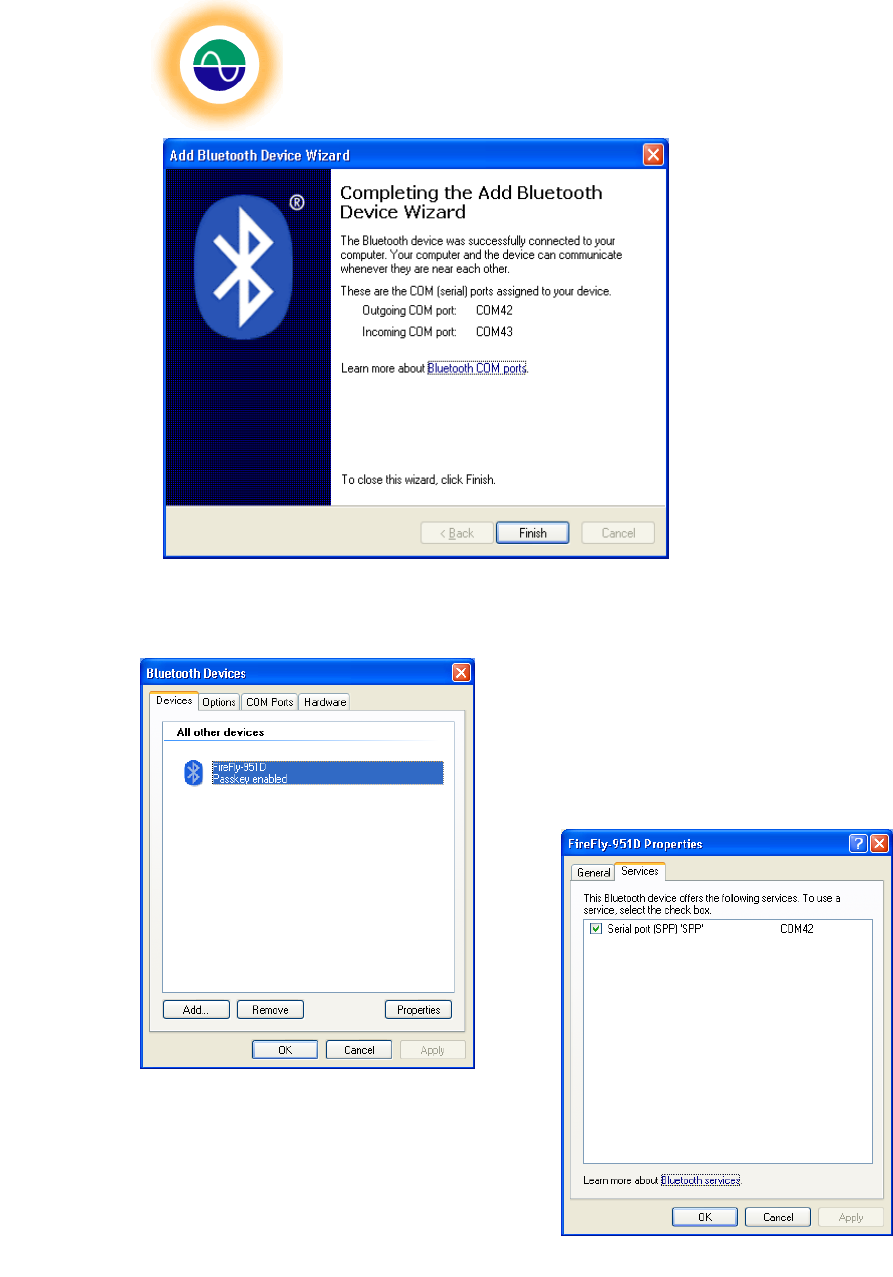
4. Next Windows will install the device.
The ST162 will identify itself as a
serial device. The operating system
will assign an available com port to
the device. The outgoing COM port
is the port that will send and receive
data. Don’t use the Incoming port –
this one is used for incoming data to
the Bluetooth radio.
5. Once the device is installed on the
host computer the com port will
automatically be used without
installing it again. To find the com
port of a previously installed device
open the Bluetooth Devices from
the control panel or from the desktop dock.
Bluetooth devices installed will be listed.
6. Highlight the Test Set Bluetooth device and click
Properties. Open the Services tab. This will list the
services that the device supports. The Test Set only
supports the Serial Port (SPP). This screen lists the com
port registered to the device.
Figure
6
-
Bluetooth Com Port Installation
Figure
7
-
Device Properties
Figure
8
-
Bluetooth Com Port

Shine Micro, Inc
. AIS Test Set
ST162
© Copyright Shine Micro, Inc., 2011. All rights reserved.
DCM-T162-UMX Revision: 1.0 Page - 22 -of 43
Appendix C – ST162 Configuration Manager
Test Set Customization
There are many customizable features available on the ST162. The test set by default sends both
message 1 and 5 once every five seconds on AIS1. This simulates one ship to test the AIS receiver
installation. The static characteristics of this simulated ship may be customized through the Test Set
Static Data Tab. In addition, the GPS behavior of the unit may be customized, via the GPS Tab, to store
the current GPS position as the unit’s default position. A default position may be set to send instead of
the current GPS position. No GPS lock is required to send the default position. This enables the GPS
antenna to be optional during operation or to ensure a known sent position for the default ship sent.
Additional messages may be configured through the Custom Tab of the Graphical User Interface (GUI),
ST162 Configuration Manager Utility, provided with the unit. The GUI will automatically open an .ini file
to set an array of 5 ships or the user may configure up to 10 ships, 1 binary message, 1 AtoN, 1 safely
related message, or 1 SART to be stored as an .ini file or just loaded to the test set. The option exists to
choose any configuration file to load. In addition the messages currently being sent by a test set may be
read and displayed using the Load Configuration File tab. Once the messages are read additional
messages may be added or the messages may be modified and saved as a configuration file. The Load
Configuration File tab allows the option to read and display an existing configuration file for editing.
The GUI also provides an interface to Reset the unit, through the Reset Tab, change the sent message
power by 31 dB through the Attenuation Tab and/or switch between Blue tooth and RS-232 as the
primary communication port, via the Serial Setting Tab.
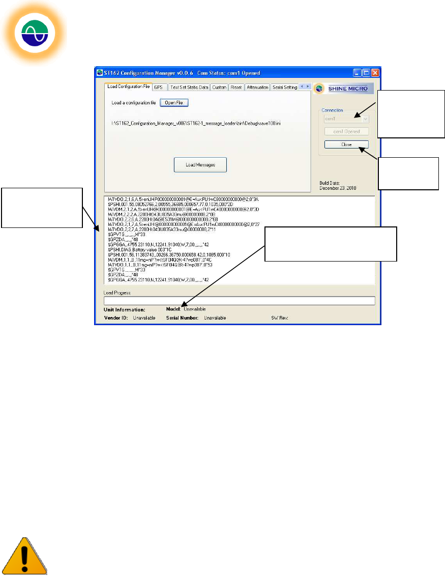
Use of ST162 Configuration Manager
To use the customized features double click on the “ST162 Configuration Manager” executable included
on the CD. This will launch the ST162 Configuration Manager interface program. The computer’s
available com ports will be displayed in the Connection drop down box. The Test Set’s default shipping
configuration is RS-232.
Choose the correct com port from the drop down menu and click the “Open” button available in the
Connection group box. The Test Set will be queried for its version and static information. This
information will be displayed in the Unit Information section see Figure . The Test Set outputs a VDO
message (AIS transmitted message) with each message sent. The VDO message contains the
encapsulated message data in NEMA 0183 v4.0 format representing the sent message. The Test Set
will also output GPS sentences $GPGGA, $GPVTG, and $GPZDA. These sentences are displayed in
the console window of the ST162 Configuration Manager. To close the connection, click the “Close”
button.
Shine Micro, Inc
. AIS Test Set
ST162
© Copyright Shine Micro, Inc., 2011. All rights reserved.
DCM-T162-UMX Revision: 1.0 Page - 23 -of 43
Figure 9 – ST162Configuration Manager Main Features
Tab: Load Configuration File
This tab allows the user to select an existing configuration file. Upon initialization of the program the
provided set of default location (contained within the ST162.ini file provided with the program) are loaded
into the PC program’s memory. Once the messages contained within a configuration file are loaded into
the Test Set, the Test Set will permanently retain and send the last loaded data until the data is reloaded
or until the “Remove Messages” button, available on the Reset Tab, is clicked.
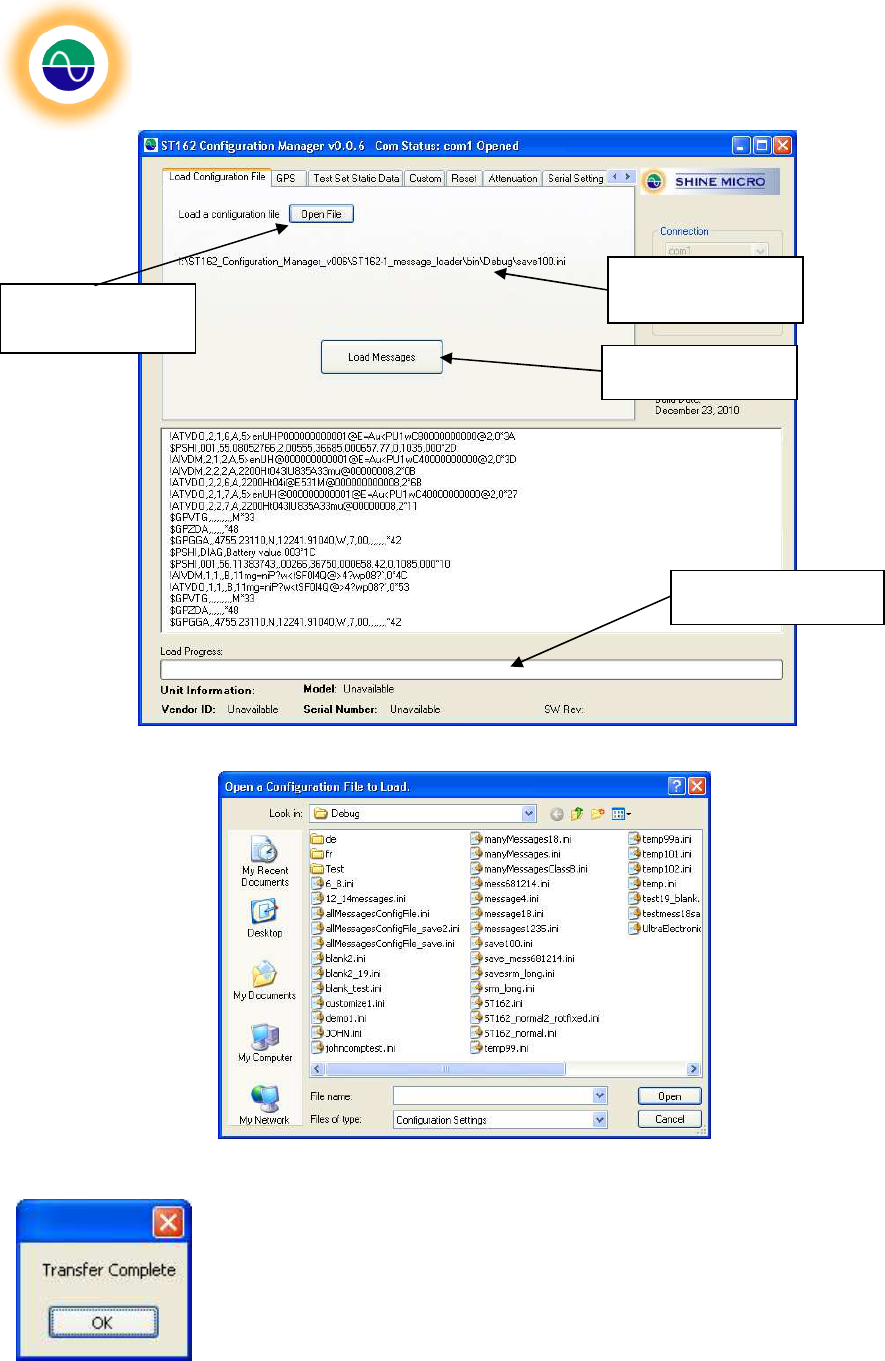
To load a configuration file other than the default, ST162.ini file click the “Open File” button and browse
to desired configuration file. See Figure . Shine Micro provides the default configuration file or the
ST162 Configuration Manager may be used to create new, customized files.
Caution! Only one set of messages contained within a configuration file may be stored to
the Test Set. Loading these messages will overwrite any other customized messages that
may have been set on the unit.
Click “Load Messages” button to load the selected configuration file. The Load Progress Bar will display
the status of the load operation. See Figure .
Unit Information Section
Open
selected
Com port
Console
Window
Close
Com port
Shine Micro, Inc
. AIS Test Set
ST162
© Copyright Shine Micro, Inc., 2011. All rights reserved.
DCM-T162-UMX Revision: 1.0 Page - 24 -of 43
Figure 10 – Load Configuration File Tab
Figure 11 - Open a Configuration File Dialog Box
Once the messages have loaded a dialog box will indicate the message were
successfully transferred to the Test Set. Click “OK” to continue.
Load Messages
Currently Loaded
Configuration File
Open a
Configuration File
Load Progress Bar
Shine Micro, Inc
. AIS Test Set
ST162
© Copyright Shine Micro, Inc., 2011. All rights reserved.
DCM-T162-UMX Revision: 1.0 Page - 25 -of 43
Tab: GPS
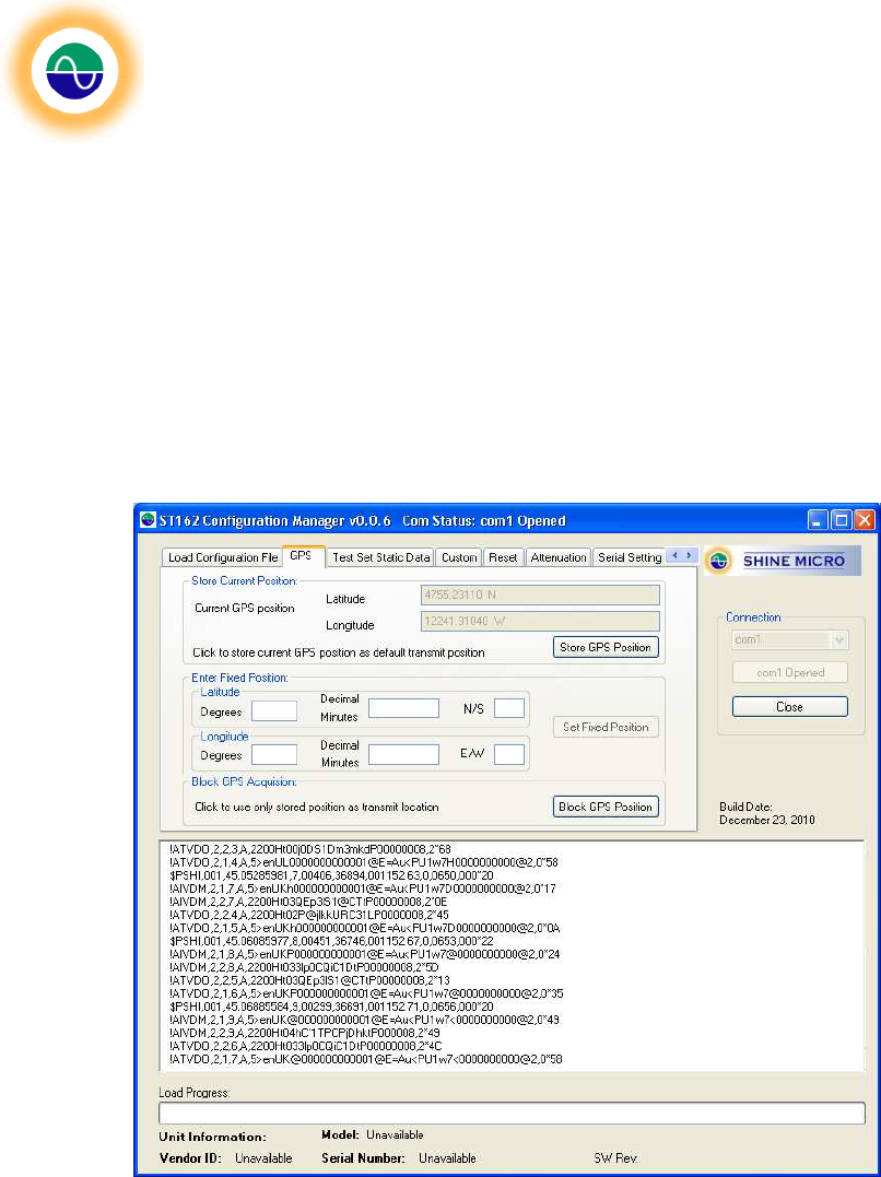
There are several different GPS options. The default configuration of the Test Set is when the unit
doesn’t have a GPS lock the unit will send the unavailable position, 91
0
N 181
0.
E.
Once a GPS position
has been stored to the Test Set this position will be used when GPS is unavailable. There are two
options to store a position:
1 If the test set is connected to a GPS signal and the locked indicator is illuminated, the current GPS
position may be stored as the Test Set’s default ship’s message 1 position.
2 The user may also choose to manually enter a fixed position to be stored as the Test Set’s default
ship’s position. The field requires that the position be entered in degrees and decimal minutes. Once
a valid position is entered the “Set Fixed Position” button will be enabled.
Figure 12 – GPS Tab
Shine Micro, Inc
. AIS Test Set
ST162
© Copyright Shine Micro, Inc., 2011. All rights reserved.
DCM-T162-UMX Revision: 1.0 Page - 26 -of 43
1. Store current position
When the unit has a GPS Lock (this is indicated with the “GPS LOCK” LED illuminated on the front
panel) the unit’s current location may be stored as the default position. To do this click the “Store
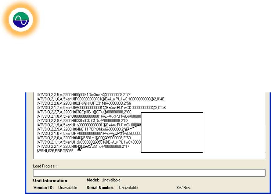
GPS Position” button. If the unit does not have GPS lock then an error will be displayed in the
console output window. See Figure .
Figure 13 – Error displayed without GPS lock
2. Enter fixed position
This tab allows the user to enter a latitude and longitude. The expected format of the latitude and
longitude is in degrees and decimal minutes.
3. Block GPS Acquisition
This allows the user to set the unit not to use the current GPS position for the default ship’s sent
position. This setting is held in volatile RAM so cycling power will clear the unit and it will return to
sending the unit’s current position if GPS is available or the default position if GPS is unavailable.
Error displayed
when Store
Position is clicked
and unit doesn’t
have GPS lock.
Shine Micro, Inc
. AIS Test Set
ST162
© Copyright Shine Micro, Inc., 2011. All rights reserved.
DCM-T162-UMX Revision: 1.0 Page - 27 -of 43
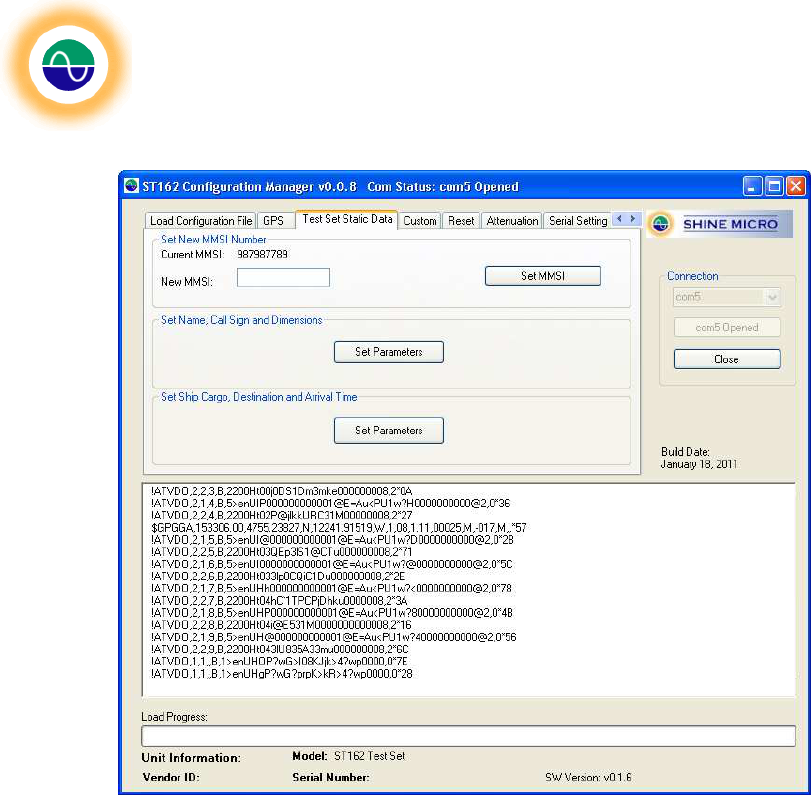
Tab: Test Set Static Data
Figure 14- Test Set Static Data Tab
There are three sets of static data which may be set on the Test set:
1. The MMSI number: The MMSI number is the assigned Maritime Mobile Service Identity which is
a unit number used to identify vessels. This number may be used by the chart plotting software
to identify the ship. The ST162’s default MMSI number is 338060087.
2. The Ship’s Static Data: The ship’s static data includes the name, call sign, and ship dimensions.
This data may be used by the chart plotting software to uniquely identify the ship. The ST162’s
default static data is: Call Sign – blank; Name – SHINE ST162 TEST SET; dimensions – 0.
3. The Ship’s Voyage Static Data: The ship’s voyage static data includes the type of ship and
cargo, destination, the arrival date and time and the navigational status of the ship. This data
may be used by the chart plotting software to uniquely identify the ship. The ST162’s default
voyage static data is: Type of Ship and Cargo – 0; destination – TEST0 DEST.
Shine Micro, Inc
. AIS Test Set
ST162
© Copyright Shine Micro, Inc., 2011. All rights reserved.
DCM-T162-UMX Revision: 1.0 Page - 28 -of 43
Set New MMSI Number:
To change the MMSI number, enter the desired MMSI number in the “New MMSI” field provided. The
MMSI number is required to be 9 numerical digits. Click “Set MMSI” to set the new MMSI number.
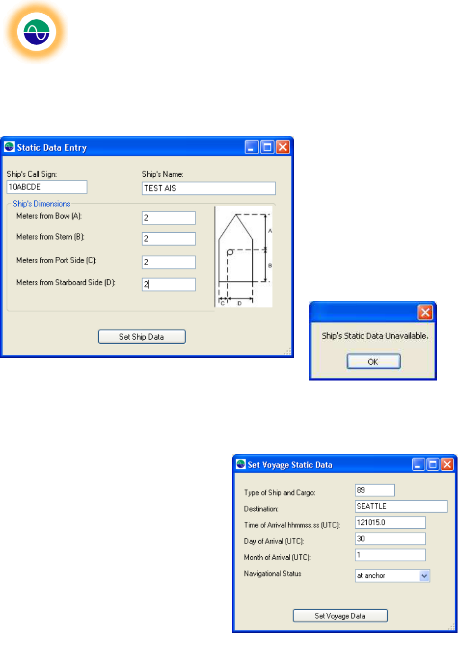
Set Name, Call Sign and Dimensions:
To set the ship’s static data click
the “Set Parameters” button in the
Set Name, Call Sign and
Dimensions group box. This will
bring up the Ship’s “Static Data
Entry” window. (Note if the
connected communication port is
not the command port and
communication fails a dialog box
will report that the ship’s static data
is unavailable). The current static
data is populated in the fields if
available. Change the data and
click “Set Ship Data”
Set Ship Cargo, Destination and Arrival Time:
To set the ship’s voyage static data click the “Set
Parameters” button in the Set Ship Cargo,
Destination and Arrival Time group box. This will
bring up the “Set Voyage Static Data” window.
The current data is populated in the fields. If the
data is unavailable (the unit doesn’t respond) then
an information box reporting that the Ship’s
voyage static data is unavailable and the fields will
be unpopulated.
Figure
15
–
Static Data Entry Screen
F
igure
16
–
Voyage Static Data Entry Screen
Shine Micro, Inc
. AIS Test Set
ST162
© Copyright Shine Micro, Inc., 2011. All rights reserved.
DCM-T162-UMX Revision: 1.0 Page - 29 -of 43
Tab: Custom
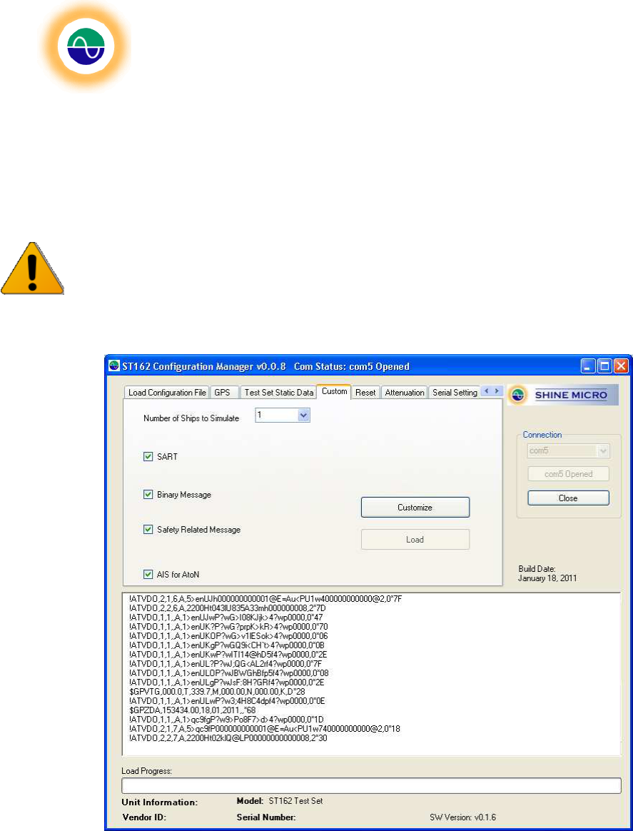
The ST162 Configuration Manager has the ability to simulate 10 ships, 1 SART, 1 binary message, 1
Safety Related Message (SRM) and 1 AIS Aid to Navigation (AtoN).
Caution! Only one set of customized messages may be stored to the Test Set. Loading these
messages will overwrite any other customized messages that may have been set on the unit.
Choose from the drop down menu the number of desired ships and/or choose the desired messages by
checking the check boxes.
Figure 17 – Custom Message Data Entry Tab
Click on the “Customize” button. This will bring up a form in which to enter the message information.
Shine Micro, Inc
. AIS Test Set
ST162
© Copyright Shine Micro, Inc., 2011. All rights reserved.
DCM-T162-UMX Revision: 1.0 Page - 30 -of 43
Simulated Ships:
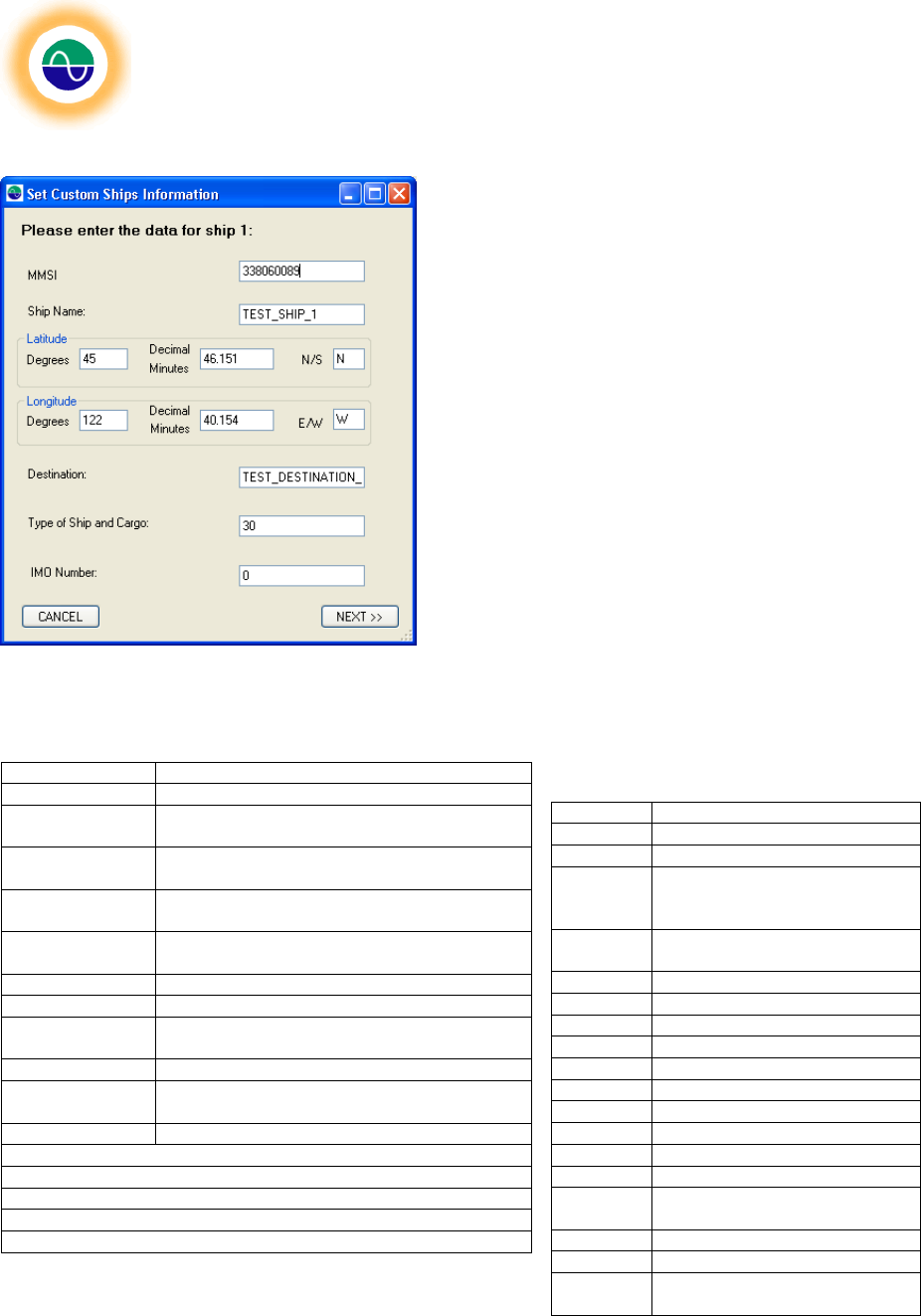
Enter the desired MMSI, ship name, location,
destination, type of ship and cargo and the IMO
number for the desired test vessel. The type of ship
and cargo ITU-R M.1371-1 definitions are included as
Table 3 and Table 4. The ship and cargo identifier is
constructed by selecting the appropriate first and
seconds digits from the tables. An example of a correct
Type of Ship and Cargo for a Fishing Vessel would be
30. This will generate a ship position report and static
and voyage related report for the simulated ship.
Table 3 - Ship Type And Cargo
Table 4 – Ship Type
Fig
ure
18
–
Simulated Ships Data Entry
First Digit Second Digit
2 - WIG 0 - All ships of this type
3 − See Table 3 1 – Carrying DG, HS, or MP, IMO hazard or
pollutant category A
4 - HSC 2 – Carrying DG, HS, or MP, IMO hazard or
pollutant category B
5 − See Table 3 3 – Carrying DG, HS, or MP, IMO hazard or
pollutant category C
6 − Passenger
ships 4 – Carrying DG, HS, or MP, IMO hazard or
pollutant category D
7 − Cargo ships 5 − Reserved for future use
8 − Tanker(s) 6 − Reserved for future use
9 − Other types
of ship 7 − Reserved for future use
8 − Reserved for future use
9 − No additional
information
HSC: High Speed Craft
WIG: Wing-In-Ground
DG: dangerous goods
HS: harmful substances
MP: marine pollutants
Identifier Special type of craft
30 Fishing
31 Towing
32 Towing and length of the tow
exceeds 200 m or breadth
exceeds 25 m
33 Engaged in dredging or
underwater operations
34 Engaged in diving operations
35 Engaged in military operations
36 Sailing
37 Pleasure craft
38 Reserved for future use
39 Reserved for future use
50 Pilot Vessel
51 Search and rescue vessels
52 Tugs
53 Port Tenders
54 Vessels with anti-pollution
facilities
55 Law enforcement vessels
58 Medical transports
59 Ships according to RR
Resolution No. 18
Shine Micro, Inc
. AIS Test Set
ST162
© Copyright Shine Micro, Inc., 2011. All rights reserved.
DCM-T162-UMX Revision: 1.0 Page - 31 -of 43
Binary Message:
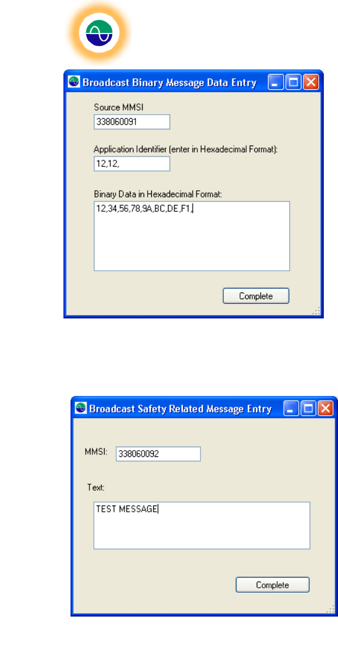
If the Binary Message box is checked the
“Broadcast Binary Message Data Entry” form
will be displayed. Enter the MMSI number,
application ID (in hexadecimal) and the
binary message (in hexadecimal). The
binary message is limited to 40 bytes of data
and the Application Identifier is limited to 2
bytes of data. The data sent will be the
same as the hexadecimal representation.
This is sent as a message 14, Binary
broadcast message.
Safety Related Message (SRM):
If the Safety Related message box is
checked the “Broadcast Safety Related
Message Entry” form will be displayed.
Enter the MMSI number and the message
data, limited to 53 characters. This data
will be sent as a message 14 Safety
Related Broadcast Message.
Figure
19
–
Binary Message Data Entry Screen
Figure
20
–
Broadcast
Safety Related Message Entry
Screen
Shine Micro, Inc
. AIS Test Set
ST162
© Copyright Shine Micro, Inc., 2011. All rights reserved.
DCM-T162-UMX Revision: 1.0 Page - 32 -of 43
AtoN:
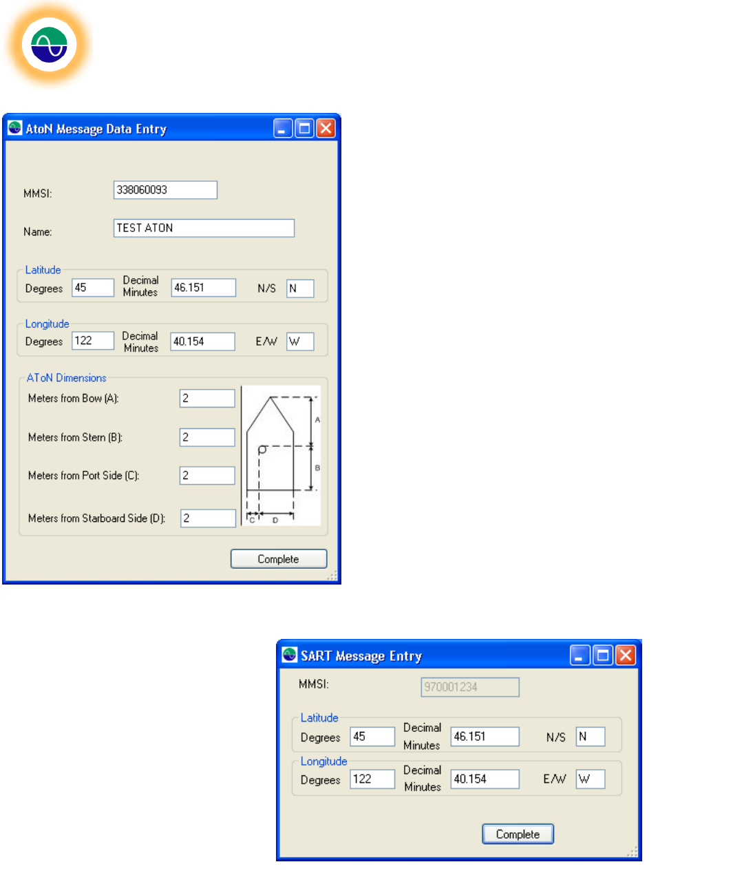
If the AtoN box is checked the “AtoN Message
Data Entry” form will be displayed. Enter the
simulation data for the AtoN. A message 21
will be generated to simulate an AtoN.
SART Message:
If the SART box is checked the “SART
Message Entry” form will be displayed.
The MMSI number is not selectable. Enter
the desired test location. A SART test
message sequence will be generated:
Message 14 “SART TEST”, followed by
three position reports, closed by a
message 14 “SART TEST” on AIS 1. All
message fields are populated in
accordance with IEC 61097-14.
Figure
21
–
AtoN Data Entry Screen
Figure
22
–
SART Message Entry Screen
Shine Micro, Inc
. AIS Test Set
ST162
© Copyright Shine Micro, Inc., 2011. All rights reserved.
DCM-T162-UMX Revision: 1.0 Page - 33 -of 43
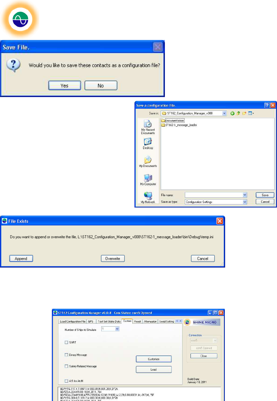
Once all selected messages have been
entered a dialog box will be displayed
prompting if you would like to save the
messages created as a configuration
file. Choose yes to save the message
list configuration file to be loaded later to
this test set or another test set.
Choosing yes will bring up a Windows Save File
dialog box. Browse to the directory where the
configuration file is to be saved. Type in a file
name and click save.
If the file exists
then a dialog box
will be displayed
giving you the
option to Append
the messages to
the existing file,
overwrite the file
or cancel the save operation. The Append option may be used add to an existing message list.
The “Load” button will be enable. Click on this button to load the customized messages created to the
Test Set.
Figure 23 – Custom Message Load Button Enabled
Shine Micro, Inc
. AIS Test Set
ST162
© Copyright Shine Micro, Inc., 2011. All rights reserved.
DCM-T162-UMX Revision: 1.0 Page - 34 -of 43
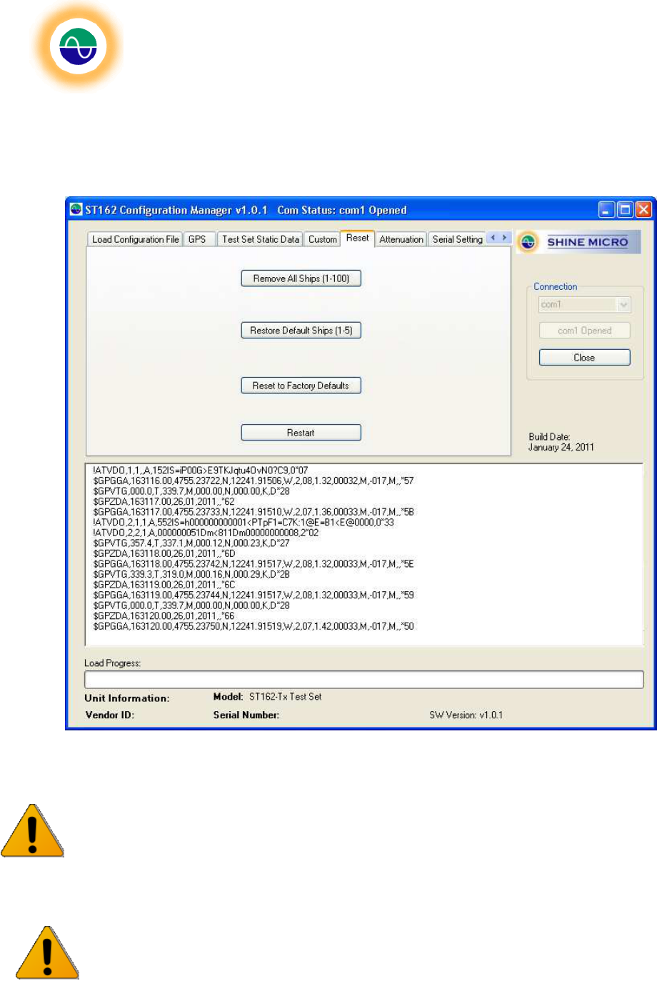
Tab: Reset
The reset tab has four options: Remove All Ships (1-100), Restore Default Ships (1-5), Reset to Factory
Defaults, and Restart.
Figure 24 – Reset Tab
Caution! Removing the messages will remove any custom data messages sent to the unit. This
will not affect the ST162 message 1 and 5, however any customized messages including the
Shine Micro defaults will be removed and the test set will only send its message 1 and 5 with the
current static data.
Caution! Resetting the unit to factory defaults will only reset the static data of the unit to
factory defaults. To restore the custom message memory to factory default values choose the
Restore Default Ships (1-5). Resetting to factory defaults will set the Test Set to RS-232
control.
Shine Micro, Inc
. AIS Test Set
ST162
© Copyright Shine Micro, Inc., 2011. All rights reserved.
DCM-T162-UMX Revision: 1.0 Page - 35 -of 43
Remove All Ships (1-100): This function will remove all messages 1 to 100 from the ST162 memory.
The ST162 will still send its message 1 and 5 with the test set static data as configured every 5 seconds.
Restore Default Ships (1-5): This function will overwrite all messages 1 to 100 with the 10 factory
default messages simulating 5 AIS ships. Any custom messages the test set is currently sending will be
overwritten. The ST162’s default message 1 and 5 will be unaffected by this function.
Reset to Factory Defaults: This function will reset the static data on the test set to factory defined
defaults as outlined in REF. The command communication port will go to RS-232. This function will not
change the custom messages 1-100.
Restart: This function provides a soft restart. Choose this option to restart the unit.
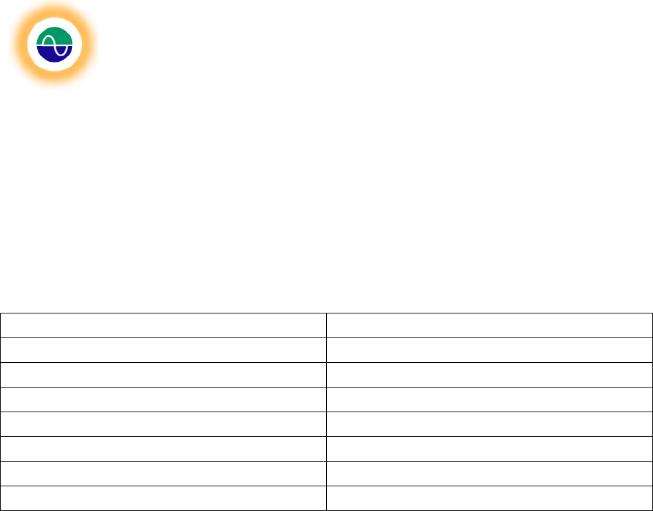
Table 5 - ST162 Static Data Default
Field Factory Default Value
MMSI 338060087
Latitude 91° N
Longitude 181° S
Ship Name SHINE ST162 TEST SET
Call Sign Blank
Type of Ship and Cargo 0
Destination TEST DEST0
Shine Micro, Inc
. AIS Test Set
ST162
© Copyright Shine Micro, Inc., 2011. All rights reserved.
DCM-T162-UMX Revision: 1.0 Page - 36 -of 43
Tab: Attenuation
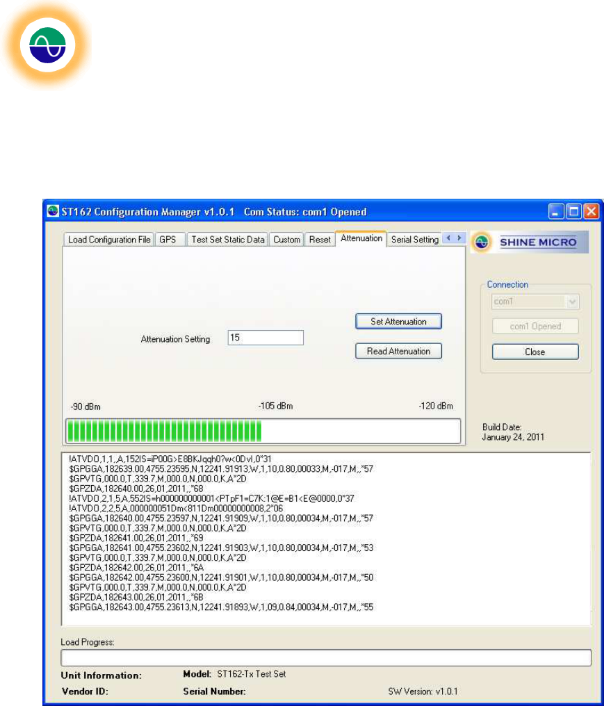
The “Attenuation” tab allows the user to set the output attenuation of the sent packets. The output
attenuation may be set from 0 to 31 dB. An attenuation setting of 0 will give the strongest signal
strength. The bar graph indicates the signal level at the EUT port. The Signal at the EUT Port is −90
dBm at 0 Attenuation to −120 dBm at 31.
Figure 25 – Output Attenuation Tab
Shine Micro, Inc
. AIS Test Set
ST162
© Copyright Shine Micro, Inc., 2011. All rights reserved.
DCM-T162-UMX Revision: 1.0 Page - 37 -of 43
Tab: Serial Setting
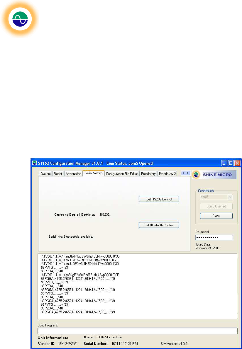
The serial setting tab allows the user to set the serial control of the unit. RS-232 data will always be
output but the Test Set will only accept commands from either the RS-232 or the Bluetooth port. The
factory default setting is RS-232 control. If the ST162 has a Bluetooth module installed, then the unit
may be switched to Bluetooth control. The ST162 will automatically sense if a Bluetooth model is
installed on the unit. If it isn’t installed, then the ST162 Configuration Manager will disable the ability to
switch to Bluetooth control and display a message. See Error! Reference source not found..
For a Test Set with an installed Bluetooth, the Serial Setting tab will have the “Set Bluetooth Control
Button” enabled and the Serial Info message will display that Bluetooth is available on this device, see
Figure . To change from RS-232 to Bluetooth control click the “Set Bluetooth Control” button. This will
change the current serial setting to Bluetooth, however the change will not take effect until the unit’s
power is cycled or the unit is restarted (by clicking the “Restart” button available on the Reset Tab).
When the unit restarts it will be in Bluetooth control. RS-232 data will still be output, however the unit will
not receive commands through the connection.
Figure 26 - Serial Setting Tab
Shine Micro, Inc
. AIS Test Set
ST162
© Copyright Shine Micro, Inc., 2011. All rights reserved.
DCM-T162-UMX Revision: 1.0 Page - 38 -of 43
Tab: Configuration File Editor
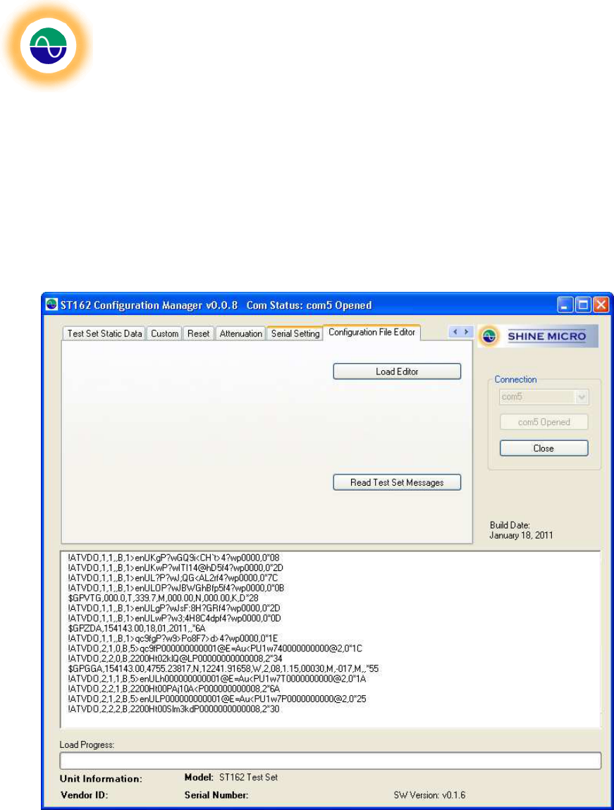
The Configuration File Editor provides an interface to view and edit a configuration file. There are two
ways to edit a configuration file:
1. Click the “Load Editor” button to browse for an existing configuration file and open it to view the
messages contained within the file.
2. The message memory from the ST162 may be read and displayed for editing by clicking on the
“Read Test Set Messages” button. Once edits are complete the message list may be saved as a
configuration file to load to the test set.
Figure 27 - Configuration File Editor
Shine Micro, Inc
. AIS Test Set
ST162
© Copyright Shine Micro, Inc., 2011. All rights reserved.
DCM-T162-UMX Revision: 1.0 Page - 39 -of 43
Message List Editor:
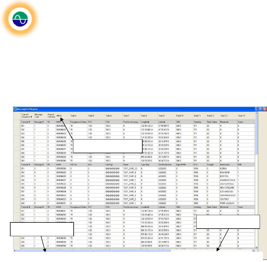
The Message List Editor provides a view of the messages being sent. The messages may be sorted,
reordered, or modified. In addition additional messages may be added. The currently support message
set includes: Messages 1, 2, 3, 5, 6, 8, 12, 14, 18, 19, 21, and 24.
Sort:
The messages may be alphabetically sorted within the editor by clicking on the column header, which
corresponds to the field to sort. See Figure . The editor loads the messages in the order that they will be
sent. To see a view of the messages in ascending MMSI order, click on the column heading “MMSI”. To
sort descending click again. Once the messages are sorted in the desired order, click on the “Insert
Message Headers” button to insert message header rows with the message type’s unique descriptions.
The sort function works for all field columns.
Add a Message:
To add a message select the row proceeding the location in the message list that the new message is to
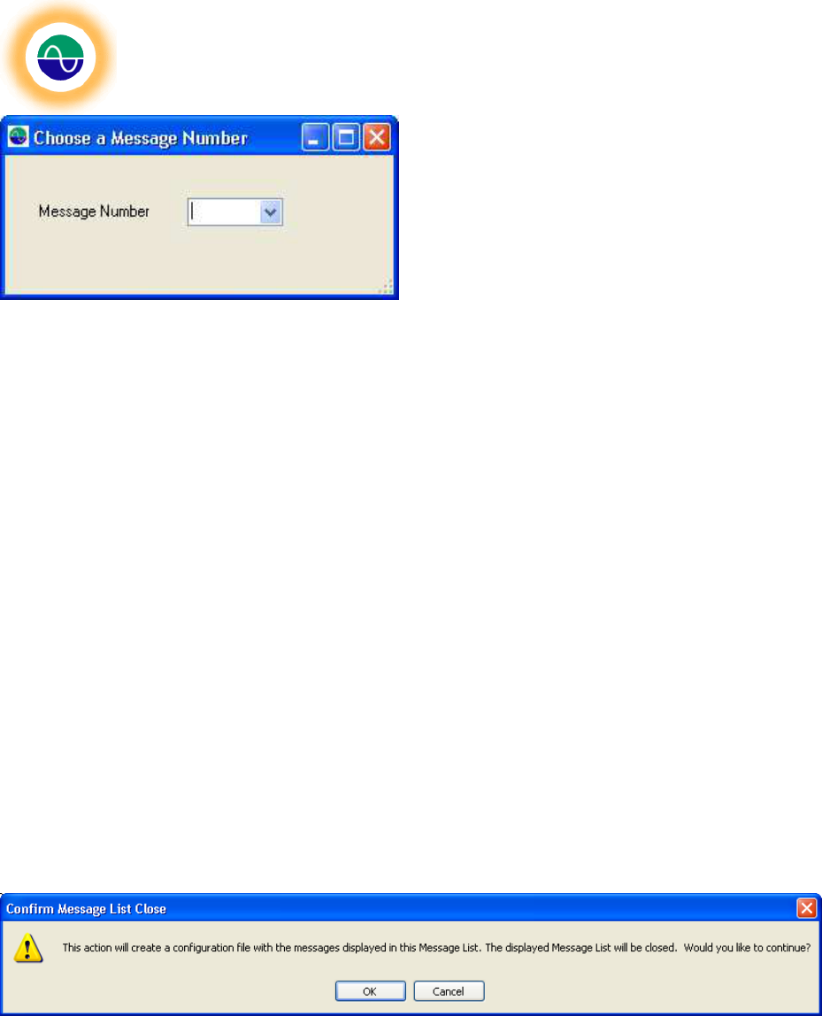
be inserted and right click. This will bring up a selection menu to: “Add a New Message”; “Add A Blank
Message”; or “Delete Selected Message”. Click on the Add a New Message option. Choose a message
number from the drop down menu.
Message Headers
Save Message List
Click to sort by MMSI
Figure 28
-
Message List View
Shine Micro, Inc
. AIS Test Set
ST162
© Copyright Shine Micro, Inc., 2011. All rights reserved.
DCM-T162-UMX Revision: 1.0 Page - 40 -of 43
This will insert a message with all settings set to “unavailable” values at message list position 0. The
messages may be modified by double clicking on the message in the Message List Display. Double
clicking on any message will open the message for editing in the Message Viewer and Editor.
Delete Selected Message:
To delete a message select the message to be removed and right click. Choose from the selection
menu “Delete Selected Message”.
Add a Blank Message:
The option to add a blank message allows the user to customize the message frequency. There is a one
slot (26.67 msec) delay between each message sent. To increase the delay between two consecutive
messages add a blank message. An added message will always by default be inserted in transmit
position 0. To change the position, double click on the message to open the Message Viewer and Editor.
Insert Message Headers:
The insert Message Headers button is located at the bottom of the Message List Viewer. See Figure .
This option will preserve the current message sort and insert descriptive message headers for each
message type. A new header is inserted describing the message fields when the message type
changes. Use this option after sorting a message list by the desired field.
Save Message List as a Configuration File:
The option to save the current Message List as a configuration file allows the user to save current list as
new configuration file to load to the test set. The Message List may be stored as a new configuration file,
replace an existing configuration file, or it may be appended to an existing configuration file. The
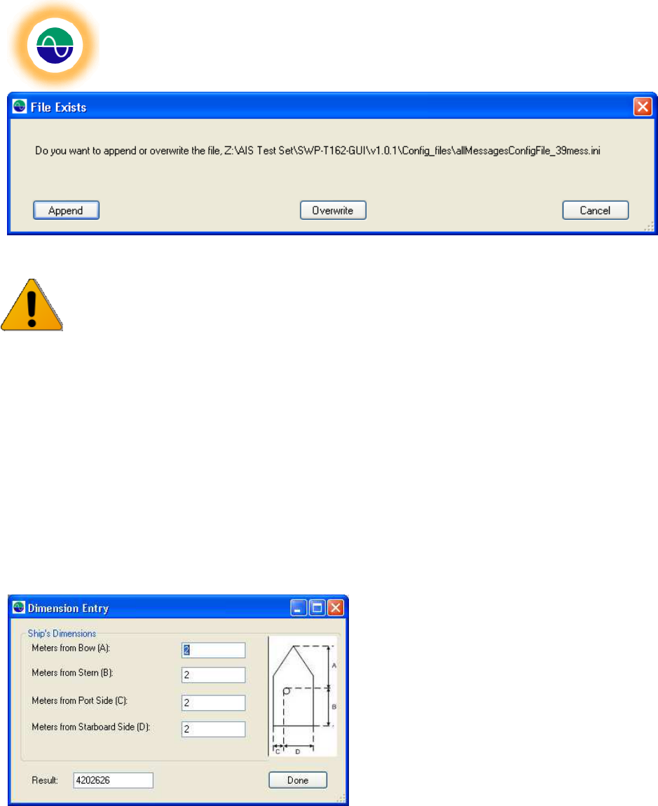
Message List is sorted by the transmit number prior to writing the file. After clicking the “Save Message
List as a Configuration File” the message list will be sorted by the transmit number. The Message List is
displayed as it will be saved. Any duplicate entries in the transmit order column will be sequentially
renumber. The sorted list is displayed within the Message List Viewer and a dialog box is displayed.
Continuing with the save will close the Message List Viewer. Click “OK” to continue.
Next, a file save dialog box is displayed. Type the name to save the configuration file under in the File
Name textbox. Click Save. If the file already exists the option is given to append to the existing file,
overwrite the existing file or cancel to choose another file name.
Shine Micro, Inc
. AIS Test Set
ST162
© Copyright Shine Micro, Inc., 2011. All rights reserved.
DCM-T162-UMX Revision: 1.0 Page - 41 -of 43
Once the Message List is saved as a configuration file the Message Viewer will be closed.
Caution: Canceling the save operation from the file save dialog box will close the current
Message Viewer.
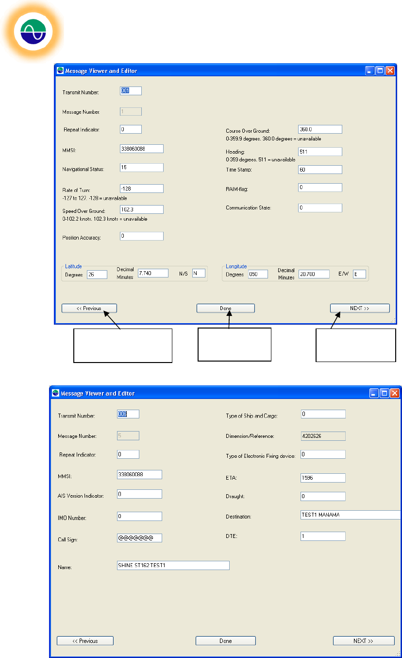
Message Viewer and Editor:
The Message Viewer and Editor provides an interface to view more detailed message information for
each type of supported message. It also provides the editor to customize each AIS message. To access
the Message Viewer and Editor double click on any message from the Message List Viewer. The
Message Viewer will display the information for the selected message. See Figure for an example of a
message 1 Message Viewer and Editor example and Figure for a message 5.
To edit the message simply enter the desired information in the boxes provided. All latitude and
longitudes are displayed in degrees and decimal minutes. The message number cannot be changed.
Once the message contains the desired information click “Next” to go the next message in the Message
List Viewer; click “Previous” to go the message before the current message in the Message List Viewer
or “Done” to close the Message Viewer and Editor and return to the Message List Viewer.
Messages 5, 21, and 24 part B all have a
dimension field. The dimension is assigned as
a A, B, C and D dimension. The dimension
field is formed through a bitwise combination of
the sizes. An interface is provided to create the
dimension field, simply double click on the
dimension textbox to launch the interface. See
Figure .
Shine Micro, Inc
. AIS Test Set
ST162
© Copyright Shine Micro, Inc., 2011. All rights reserved.
DCM-T162-UMX Revision: 1.0 Page - 42 -of 43
Figure 29 - The Message Viewer and Editor - Message 1 Example
Figure 30 - The Message Viewer and Editor - Message 5 Example
Back to the last
message in the list Return to
Message List Next message
in the list

Shine Micro, Inc
. AIS Test Set
ST162
© Copyright Shine Micro, Inc., 2011. All rights reserved.
DCM-T162-UMX Revision: 1.0 Page - 43 -of 43
Appendix D - Troubleshooting
Unable to connect via Bluetooth:
If you are unable to connect to the Test Set via Bluetooth, try removing the Bluetooth device from the
PC’s “Bluetooth Devices” and then add it again as described in “Configuring Bluetooth Communication”
above . If you are using a Bluetooth dongle via USB, you may need to remove the dongle and then plug
it back in.
GPS LOCK LED Flashes:
The GPS LOCK LED strobes when the batteries are low. Replace the batteries.
New Batteries Installed but Test Set Won’t Power Up:
Both batteries should be installed with the positive terminals facing up. Ensure the battery caps are
securely tightened.