Shure orporated FP3M Wireless Microphone Transmitter User Manual Exhibit D Users Manual per 2 1033 c3
Shure Incorporated Wireless Microphone Transmitter Exhibit D Users Manual per 2 1033 c3
Exhibit D Users Manual per 2 1033 c3

1
FP Wireless System
Features
• AudioReferenceCompandingforcrystal-clearaudio
• AutomaticFrequencySelectionlocatesanopenfrequencyatthetouchofabutton
• AutomaticTransmitterSetupinstantlysyncsthetransmittertothereceiverfrequency
• Upto12compatiblesystemssimultaneously
• Allcomponentspoweredby2AAbatteries–nopowercordrequired
• Transmittergainattenuationcontrolmanagesinputlevel
FP1 Bodypack Transmitter
Lightweight,durablehous-
ing;forusewithTA4F-
connectionmicrophones
includinglavaliersand
headsets
FP2 Handheld Transmitter
Lightweight,durable
housing;availablewith
eitherthelegendary
ShureSM58®cardioid
dynamicwirelesscap-
suleorwiththeVP68
condenseromnidirec-
tionalcapsule;compat-
iblewithallShurewire-
lesscapsules
FP3 Plug-On Transmitter
Durablemetalhousing,
ergonomicallydesigned
forcomfortablegrip;
XLRconnectivityallows
forusewithanywireddynamicXLR
microphone
FP5 Portable Receiver
Lightweight,durable
housing,suitablefor
mountingoncameraor
person,diversityanten-
nas,outputviaTA3F
cabletoeitherXLRor
1/8”connectors.
Featuringacomprehensiveselectionofsystemconfigurationswithkeywirelessaudiotechnologiesandcomponents,FPWirelessprovidestheabilitytocap-
turecrystal-clearaudiowithconfidence.Withsimpleandflexiblecomponents,includingaportablereceiverandXLRplug-ontransmitter,ithasneverbeen
easierforaudiotobecapturedinthedemandinganddynamicvideographyandelectronicfieldproduction(EFP)environments.
Furnished Accessories
Micrphone Clip (FP2) Plug-on Transmitter Belt Clip and
Protective Skin (FP3)
Camera Shoe Mount (FP5) TA3F-to-XLRm Audio Cable
TA3F-to-3.5mm Dual-mono Audio
Cable

FP1-FP5 FP3FP2
FP1
2
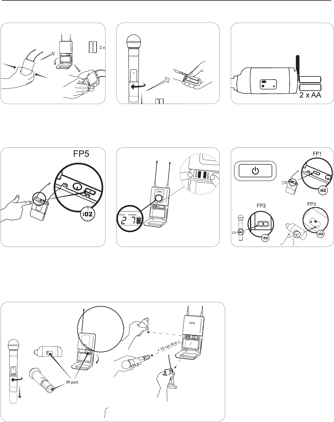
Quickstart
Install Batteries
Power up the FP5 Receiver Group scan for open frequencies Power up the transmitter
Sync transmitter and receiver

FP5
3
1
2
3
PGX1
4
5
PGXD
1
2
1 2
5
3
6
FP1 FP2
FP3
3
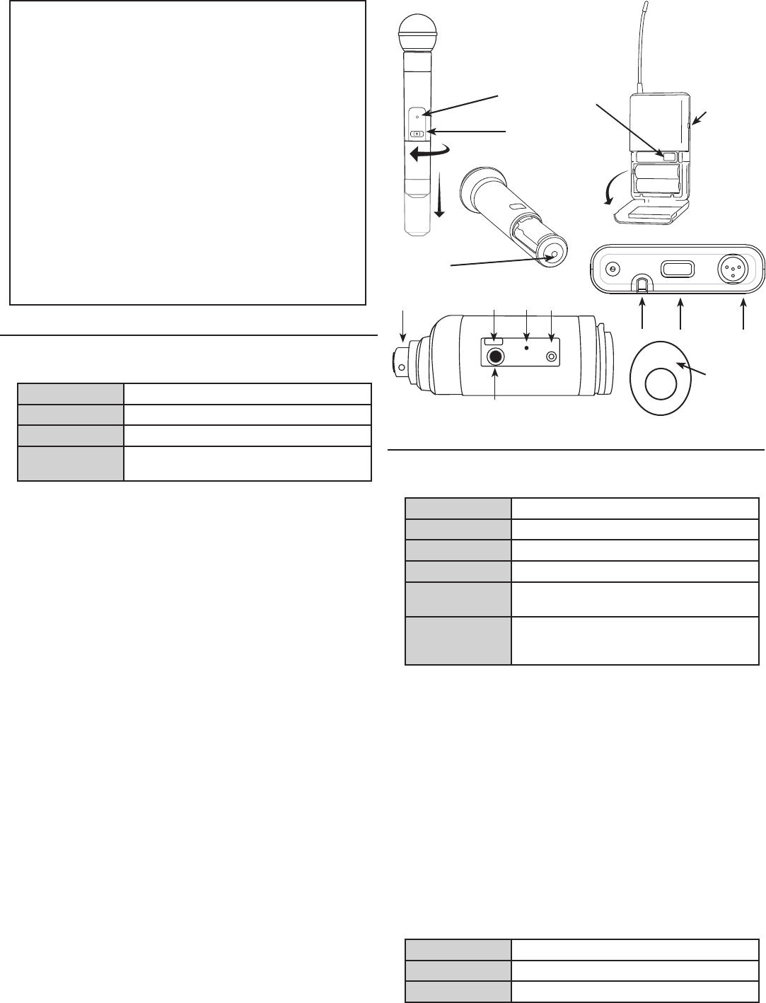
FP5 Receiver
①PowerLED
Green Poweron
Yellow Lowbatteryalert
Red Criticallowbattery,replaceimmediately
Flashingredon
powerup
Batterydead
②RFLED
Illuminateswhensuccessfullysyncedtoatransmitter(ormanually
tunedtoatransmitter'sfrequency)
③PowerButton
Pressandholdtopoweronoroff.
④Infrared(IR)port
Sendsinfraredbeamtosynchronizefrequencies.
⑤TA3MJack
UsewithTA3Fcableforaudioout.
⑥AudioOutputGain
Adjustaudiooutputleveltodevicessuchascamerasorrecorders.
⑦LCDScreen
DisplayscurrentsettingsforGROUPandCHANNELandbatterylife.
⑧ScanButton
Group scan: Pushandhold(3sec.)tofindanopengroupandchannel.
Channel scan: Pushandreleasetofindanopenchannelinthecurrent
group.
⑨Syncbutton
Alignreceiverandtransmitterandpresssync.BlueIRLEDindicates
successfulsync.
Note: Presssyncandscanbuttonstomanuallyentergroupandchan-
nelnumbers
⑩Antennas
Twoantennasfordiversityreception.
Transmitter Controls and Connectors
①IndicatorLED
Green Ready
Flashinggreen Controlslocked
Flashingred IRtransmissioninprogress
Solidred Batterypowerlow
Flashingredon
startup
Batteriesdead(transmittercannotbeturned
onuntilbatteriesarechanged)
Rapicflashing
redafter
synchronization
Transmitterandreceiveincompatible;contact
yourShurereseller
②PowerButton
Pressandholdtopoweronoroff.
③Infrared(IR)Port
Receivesinfraredbeamtosynchronizefrequencies.Whenusing
multiplesystems,onlyonetransmitterIRportshouldbeexposedata
time.
④4-PinMicrophoneInputJack
UsewithwithaTA4Fconnectorforalavalierorheadsetmicrophone.
⑤AudioInputGain
Adjustsaudiolevel.
⑥XLRConnection(FP3only)
PlugintoanXLRmicrophoneortheoutputofanaudiodevice.
⑦AudioInputLevelIndicator(FP3only)
Red Signalclip
Yellow Nominalpeak
Green Audiopresent
7

PGXD
BIAS
AUDIO
0dB -10dB
AUDIO
0dB -10dB
FP2
FP1
FP3
0
-10dB
mic
0
-10dB
mic
4
Adjusting Gain
FP1 and FP3
Performasoundcheck.Usethe
audiogaincontrollocatedonthe
side(FP1)orfront(FP3)ofthe
unittoadjustthegainup(+)or
down(−)untildesiredlevelis
reached.
FP3 only: Adjustsotheaudio
inputlevelindicatorflickersyellow
atpeaksoundlevels.
FP2
Thehandheldtransmitternormally
doesnotrequireadjustmentand
should be left at 0dBformostappli-
cations.Onlyusethe–10dBsettingfor
loudsingingorotherhighSPLapplica-
tionsifthereisnoticabledistortion.
Accessthegainadjustmentswitch
byunscrewingtheheadofthe
microphone.Usethetipofapen
orasmallscrewdrivertomovethe
switch: 0dB: Fornormaluse.
–10dB: UseonlyifaudiodistortsduetohighSPLlevels.
Single System Setup
1.Perform a group scan:
Pressandholdthescanbuttonfor3seconds.Afterthescancom-
pletes,thenewgroupandchannelisautomaticallyactivatedand
saved.
2.Synchronize the transmitter:
Alignthetransmitterandreceiverinfrared(IR)portsandpressthe
syncbutton.
Afterasuccessfulsync,thetransmitterLEDmomentarilyflashesand
theblueRFLEDilluminates.
Multiple System Setup
Usethefollowingstepstoensurethebestperformancewhenusingmul-
tiplewirelesssystemsatthesamelocation.
1.Turnallreceiversonandalltransmittersoff.
Note: Turnonanyotherdigitalequipmentthatcouldcauseinterfer-
enceduringtheperformancesoitwillbedetectedduringthefrequen-
cyscansinthefollowingsteps.
2.Performagroupscanusingthefirstreceiverbypressingandholding
thescanbuttonfor3seconds.
3.Turnonthefirsttransmitterandsyncittothereceiver.
For each additional system:
1.Manuallysetthegroupnumbertomatchthefirstreceiver(seeManual
GroupandChannelSelection).
2.Performachannelscanbypressingthescanbutton.
3.Syncthetransmittertothereceiver.
Important: Aftersyncingeachtransmitter,leaveitonsothatscansfrom
theotherreceiversdonotselectthatchannel.Besureonlyonetransmit-
terIRportisexposedwhensynchronizingeachsystem.
Manual Group and Channel Selection
(receiver only)
Important: Mostsingle-systemapplicationsdonotrequiremanualgroup
orchannelsettings--useanautomaticfrequencyscaninstead.However,
itmaybeusefulforsomeapplications,suchastotunetoandrecordau-
diodirectlyfromamicrophoneinacompatiblewirelessinstallation.
To set the group:
1.Pressthescanandsyncbuttonssimultaneously.TheGROUPdisplay
flashes.
2.Pressthesyncbuttontochangethegroupnumber.
3.Pressscantoaccepttheselectedgroup.
4.Pressscanagaintosaveandexit.
5.Ifdesired,performachannelscantoselectanopenchannelinthat
group.
To set the channel:
1.Pressthescanandsyncbuttonssimultaneously.TheGROUPdisplay
flashes.
2.Pressscantomovetothechannelsetting.TheCHANNELnumber
flashes.
3.Pressthesyncbuttontoadvancetothedesiredchannelnumber.
4.Pressscantosaveandexit.
Note: Remembertosyncthetransmittertothereceiver.
Automatic Frequency Scan
IfyouexperienceRFinterference,switchtoanewchannelusingthe
channelorgroupscan.
Channel scan: Pressthescanbuttononthereceiver.Switchestonew
channelinthesamegroup.
Group scan: Pressandholdthescanbuttonfor3seconds.Findsanew
groupandselectsanopenchannelinthatgroup.(Donotuseinmultiple
systemsetupsunlessallsystemsaremovedtothesamegroup.)
Locking and Unlocking the Transmitter
Lockingthetransmitterpreventsaccidentalchangesduring
performances.
To lock the controls: Withthetransmitteroff,holdthepowerbutton
downuntilthegreenLEDflashes(~5seconds)
To unlock the controls: Withthetransmitteron,holdthepowerbutton
downuntilthegreenLEDflashes(~5seconds)

5
Troubleshooting
Issue Indicator Status Solution
Nosoundorfaintsound Transmitterpowerlighton,receiver
blueRFLEDoff
Syncthetransmittertothereceiver
Moveclosertoandmaintainline-of-sightwiththetransmitter.Move
awayfrommetalsurfacesanddigitalequipment.
Transmitterpowerlighton,receiver
blueRFLEDon
Verifyallsoundsystemconnections
Adjustgainsettingsonthetransmitterandreceiver.Makesurethe
handheldtransmittergainisatthe0dBsetting.
ReceiverpowerLEDoff,red,or
blinkingred
Insertfreshbatteriesorpoweronthereceiver
TransmitterpowerLEDredor
flashingred
Replacetransmitterbatteries
Ifindicatorcontinuesflashingredafterbatteriesarereplaced,the
transmitterandreceivermaybelongtoincompatiblefrequency
bands.ContactyourShureresellerforassistance.
TransmitterpowerLEDoff Turnontransmitter
Makesurethe+/-indicatorsonbatteriesmatchthetransmitter
terminals
Insertfreshbatteries
Distortionorunwantednoise
bursts
N/A RemovenearbysourcesofRFinterference(CDplayers,computers,
digitaleffects,in-earmonitorsystems,etc.)
Changereceiverandtransmittertoadifferentfrequency
Reducetransmittergain
Replacetransmitterbatteries
Ifusingmultiplesystems,changethefrequencyofoneoftheactive
systems
Distortionincreasesgradually TransmitterorreceiverpowerLED
red
Replacebatteries
Cannotturntransmitteror
receiveron
PowerLEDflashingred Replacebatteries
Tips for Improving System Performance
• Maintainaline-of-sightbetweentransmitterandreceiver
• AvoidproximitytometalsurfacesanddigitalequipmentthatcouldcauseRFinterference,suchascomputers,LCDscreens,andotheraudio
electronics.
Furnished Accessories
Micrphoneclip(FP2) WA371
Plug-onTransmitterbeltclipandprotectiveskin(FP3) AFP301
CameraShoeMount(FP5) AFP511
TA3F-to-XLRmaudiocable WA451
TA3F-to-3.5mmdual-monoaudiocable WA461

6
BAND Range Transmitteroutput*
G4 470-494MHz 30mW
G4E 470-494MHz 10mW
G5 494-518MHz 30mW
G5E 494-518MHz 10mW
H5 518-542MHz 30mW
H5E 518-542MHz 10mW
J3 572-596MHz 30mW
K3E 606-630MHz 10mW
L4 638-662MHz 30mW
L4CN 638-662MHz 30mW
L4E 638-662MHz 30mW
P4 702-726MHz 30mW
P4CN 702-726MHz 30mW
Q24 736-754MHz 30mW
R13 794-806MHz 20mW
R19 794-806MHz 10mW
R5 800-820MHz 20mW
JB 806-810MHz 10mW
S6 838-865MHz 10mW
X4 925-932MHz 10mW
*Conductiveinto50ohms
SPECIFICATIONS
Frequency Range and Transmitter Output Level
NOTE:ThisRadioapparatusmaybecapableofoperatingonsome
frequenciesnotauthorizedinyourregion.Pleasecontactyournational
authoritytoobtaininformationonauthorizedfrequenciesforwireless
microphoneproductsinyourregion.
Working Range
Line of Sight
100m(300ft)
Note:ActualrangedependsonRFsignalabsorp-
tion,reflectionandinterference.
Tonekey 32.768kHz
Audio Frequency Response 45–15000Hz
Note:Dependentonmicrophonetype
Total Harmonic Distortion
Ref. ±38 kHz deviation with 1 kHz
tone
<0.5%,typical
Dynamic Range >100dB,A-weighted
Operating Temperature Range -18°C(0°F)to+50°C(122°F)
Note:Batterycharacteristicsmaylimitthisrange.
FP1
Gain Adjustment Range −10–+20dBV
Input Impedance 1MΩ
RF Output Power 10–30mW
variesbyregion
Pin Assignments
TA4M
1: ground(cableshield)
2: +5VBias
3: audio
4: Tiedthroughactiveloadtoground(Oninstru-
mentadaptercable,pin4floats)
Dimensions 108mmx64mmx19mm(HxWxD)
Weight 81g(3oz.),withoutbatteries
Housing Moldedpolycarbonatecase
Power Requirements LR6AAbatteries,1.5V
Battery Life upto12hours(alkaline)
FP2
Maximum Input Level at –10 dB gain setting: +2dBV
at 0 dB gain setting: –8dBV
Gain Adjustment Range 10dB
RF Output Power 10–30mW
variesbyregion
Dimensions 254mmX51mmdia.(10X2in.)
Weight 290g(10.2oz.)(withoutbatteries)
Housing MoldedPC/ABShandleandbatterycup
Power Requirements LR6AAbatteries,1.5V
Battery Life upto12hours(alkaline)
FP3
Gain Adjustment Range −10–+20dBV
Input Impedance 1MΩ
RF Output Power 10–30mW
variesbyregion
Dimensions 99mmx66mmx23mm(HxWxD)
Weight 207g(7.3oz.),withoutbatteries
Housing Moldedpolycarbonatecase
Power Requirements LR6AAbatteries,1.5V
Battery Life upto12hours(alkaline)
FP5
Dimensions 108mmX64mmX19mm(HxWxD)
Weight 81g(3oz.
Housing Moldedpolycarbonatecase
Sensitivity -108dBm for12dBSINAD,typical
Power Requirements LR6AAbatteries,1.5V
Battery Life upto12hours(alkaline)
Audio Output (UR5)
Type TA3F
Configuration Impedancebalanced
Pin Assignments 1=ground,2=hot,3=cold
Maximum Audio Output Level
Ref. ±38 kHz deviation with 1 kHz
tone
–13dBV(into600Ωload)
Impedance 200Ω

7
Certifications
FP1, FP2, FP3, FP5
ThisClassBdigitalapparatuscomplieswithCanadianICES-003.Cet
appareilnumériquedelaclasseBestconformeàlanormeNMB-003du
Canada.
Meetsrequirementsofthefollowingstandards:EN300422Parts1and2,
EN301489Parts1and9,EN60065.
MeetsessentialrequirementsofthefollowingEuropeanDirectives:
• R&TTEDirective99/5/EC
• WEEEDirective2002/96/EC,asamendedby2008/34/EC
• RoHSDirective2002/95/EC,asamendedby2008/35/EC
Note:Pleasefollowyourregionalrecyclingschemeforelectronicwaste
FP5
ApprovedundertheDeclarationofConformity(DoC)provisionofFCCPart
15.
CertifiedbyICinCanadaunderRSS-123andRSS-102.
IC: 616A-FP5L,616A-FP5M,616A-FP5A,616A-FP5B,616A-FP5C
FP1, FP2, FP3
TypeAcceptedunderFCCParts74.
FCC: DD4FP3L,DD4FP3M,DD4FP3A,DD4FP3B,DD4FP3C,
DD4SLX1G4,DD4SLX1G5,DD4SLX1,DD4SLX2G4,DD4SLX2G5,
DD4SLX2.
CertifiedbyICinCanadaunderRSS-123andRSS-102.
IC: 616A-FP3L,616A-FP3M,616A-FP3A,616A-FP3B,616A-FP3C,
616A-SLX1G4,616A-SLX1G5,616A-SLX1,616A-SLX2G4,
616A-SLX2G5,616A-SLX2.
ThisdevicecomplieswithIndustryCanadalicence-exemptRSS
standard(s).Operationofthisdeviceissubjecttothefollowingtwocondi-
tions:(1)thisdevicemaynotcauseinterference,and(2)thisdevicemust
acceptanyinterference,includinginterferencethatmaycauseundesired
operationofthedevice.
LeprésentappareilestconformeauxCNRd'IndustrieCanadaapplicables
auxappareilsradioexemptsdelicence.L'exploitationestautoriséeaux
deuxconditionssuivantes:(1)l'appareilnedoitpasproduiredebrouil-
lage,et(2)l'utilisateurdel'appareildoitacceptertoutbrouillageradioélec-
triquesubi,mêmesilebrouillageestsusceptibled'encompromettrele
fonctionnement.
TheCEDeclarationofConformitycanbeobtainedfromShure
IncorporatedoranyofitsEuropeanrepresentatives.Forcontactinforma-
tionpleasevisitwww.shure.com
TheCEDeclarationofConformitycanbeobtainedfrom:www.shure.com/
europe/compliance
AuthorizedEuropeanrepresentative:
ShureEuropeGmbH
HeadquartersEurope,MiddleEast&Africa
Department:EMEAApproval
Jakob-Dieffenbacher-Str.12
75031Eppingen,Germany
Phone:49-7262-92490
Fax:49-7262-9249114
Email:info@shure.de
LICENSINGINFORMATION
Licensing:Aministeriallicensetooperatethisequipmentmayberequired
incertainareas.Consultyournationalauthorityforpossiblerequirements.
ChangesormodificationsnotexpresslyapprovedbyShureIncorporated
couldvoidyourauthoritytooperatetheequipment.LicensingofShure
wirelessmicrophoneequipmentistheuser’sresponsibility,andlicens-
abilitydependsontheuser’sclassificationandapplication,andonthe
selectedfrequency.Shurestronglyurgestheusertocontacttheappropri-
atetelecommunicationsauthorityconcerningproperlicensing,andbefore
choosingandorderingfrequencies.
Note:EMCconformancetestingisbasedontheuseofsuppliedandrec-
ommendedcabletypes.TheuseofothercabletypesmaydegradeEMC
performance.
Changes or modifications not expressly approved by the manufac-
turer could void the user’s authority to operate the equipment.
Information to the user
Thisequipmenthasbeentestedandfoundtocomplywiththelimitsfora
ClassBdigitaldevice,pursuanttoPart15oftheFCCRules.Theselimits
aredesignedtoprovidereasonableprotectionagainstharmfulinterference
inaresidentialinstallation.Thisequipmentgeneratesusesandcanradiate
radiofrequencyenergyand,ifnotinstalledandusedinaccordancewith
theinstructions,maycauseharmfulinterferencetoradiocommunications.
However,thereisnoguaranteethatinterferencewillnotoccurinaparticu-
larinstallation.Ifthisequipmentdoescauseharmfulinterferencetoradio
ortelevisionreception,whichcanbedeterminedbyturningtheequipment
offandon,theuserisencouragedtotrytocorrecttheinterferencebyone
ormoreofthefollowingmeasures:
• Reorientorrelocatethereceivingantenna.
• Increasetheseparationbetweentheequipmentandthereceiver.
• Connecttheequipmenttoanoutletonacircuitdifferentfromthatto
whichthereceiverisconnected.
• Consultthedealeroranexperiencedradio/TVtechnicianforhelp.
WARNING: Dangerofexplosionifbatteryincorrectly
replaced.OperateonlywithShurecompatiblebatteries.
WARNING: Batterypacksshallnotbeexposedto
excessiveheatsuchassunshine,fire,orthelike.
8