Shuttle PN18 XPC 802.11 b/g Wireless Kit User Manual
Shuttle Inc. XPC 802.11 b/g Wireless Kit Users Manual
Shuttle >
Users Manual

User’s Guide
for
XPC 802.11b/g Wireless Kit

Shuttle®
User’s Guide for XPC 802.11b/g Wireless Kit
Manual Version 1.0
FCC Regulation Information
The equipment has been tested and f ound to comply w ith the limits for a Class B Digital
Dev ice, pursuant to part 15 of t he FCC rules. Thes e limits are designed to prov ide
reasonable protection against harmful interf erence in a residential installation. This equip-
ment generates, uses and can radiate radio frequency energy and, if not installed and
used in accordanc e w ith the ins tructions, may caus e har mful interf erence to radio
communication. How ever, there is no guaran tee that interference w ill not occur in a
par ticular installation. If this equipment does cause harmful interf erenc e to radio or
television reception, w hich can be determined by turning the equipment of f and on, the
user is encouraged to try to correct the interference by one or more of the follow ing
measures:
Reorient or relocate the receiving antenna.
Increase the separation betw een the equipment and receiver.
Connect the equipment into an outlet on a circuit different from that to w hich the
receiver is connected.
Consult the dealer or an experienced radio/TV technician for help.
The equipment is for home or of fice use.
Copyright
Copyright©2005 by Shuttle®Inc.All Rights Reserved. This publication, including all photos,
illustrations, and sof tw are, is protected under international copyright law s. Reproducing
any of the material contained herein is prohibited w ithout the consent of the publisher.
Disclaimer
Shuttle®Inc.shall not beliable f or any incidental or consequential damages resulting from
the use of this product. This company makes no representations or w arranties regard-
ing the contents of this manual. This company reserves the right to revise the manual or
make changes in the spec ifications of the pr oduct described herein at any time and
w ithout notice and w ithout obligation to notify any person of such revision or changes.
General Notice: All the other trademarks and registered trademarks are the property
of their respective ow ners.

1. Introduction ............................................................................ 1
1.1 Features ........................................................................... 1
1.2 Package Contents ............................................................ 2
1.3 System Requirements ...................................................... 2
2. Insta llation Of The X PC 802.11b/g Wireless Kit ....................... 3
2.1 Hardw are Setup ............................................................... 3
For P series ...................................................................... 4
For i series ........................................................................ 5
For G,G2,G4,G5 series ....................................................... 6
For K series ...................................................................... 8
2.2 Software Insta llation ....................................................... 11
2.3 Network Connection .........................................................14
2.4 IP Address .......................................................................18
2.5 Configuration Utility ........................................................19
2.6 Station .............................................................................21
More Setting ....................................................................23
Advanced Setting .............................................................27
2.7 Access Point ....................................................................29
More Setting ....................................................................31
3. Appendix ...............................................................................34
3.1 SoftAP Configuration ......................................................34
3.2 Specifications.................................................................39
Table of Contents
9M0-PN1801-0000

1
1. Introduction
The XPC 802.11b/g Wireless Kit aims to let your XPC quickly and
seamlessly communicate with a 802.11b/g (at up to 54 Mbps)
networks. Wireless networking uses radio frequencies to transmit
and rec eive data between your XPC’s and other network devices.
With this Wireless Kit, surfing on the Internet couldn’t be any easier.
Simply install the USB connector to the reserve header on
mainboard, launch the attached friendly-interfaced program- Shuttle
Wireless tool to configure the Module, and you will be ready to
ex peri enc e a LAN (loc al area network) that c an be ac cess ed
anywhere. You can operate the network in either an independent
mode or an infrastructure mode. The former, which is also known
as peer-to-peer or ad-hoc network, lets you directly make connec-
tion with other wireless-equipped computers, and the later, the so-
called infrastructure network, allows you to communicate with wired
LAN via an access point. To obtain the complete benefits your XPC
802.11b/g Wireless Kit provides, please read this manual carefully
before using it.
1.1 Features
With XPC 802.11b/g Wireless Kit, you can
exchange data over the air, which minimizes the need for wired
connections.
possess the portabilit y and mobili ty of wireless networki ng
connectivity wherever you are.
operate Ad-Hoc or Infrastructure modes.
utilize up to 256-bit WEP,WPA encryption.
enjoy high-speed data transfer rate up to 54 Mbps.
employ automatic data rate switc hing which offers max imum
reliability, throughput and connectivity.
monitor and configure the network vi a t he supplied friendly-
interfaced application ~ Shuttle Wireless Tool.
Operate a Software Access Point to share your internet
connection with friend family.

2
1.2 Package Contents
Before starting installation, please make sure the package you pur-
chased includes the following items:
One XPC 802.11b/g Wireless Kit
One Antenna
One Antenna cable
Two USB cable (1*5 pin & 2*5 pin)
One Ch assi s
4xScrews
One Driver CD with Shuttle SoftAP
One User Manual
If any of the items list ed above are missing or damaged, please
contact your distributor.
1.3 System Requirements
To properly operate your XPC 802.11b/g Wireles s Kit, your com-
puter must meet the following minimum requirements:
Pentium III MHz processor or higher
128 MB RAM or above
A CD-ROM drive
Microsoft Windows 98 SE/ Me/ 2000 or Windows XP
3
2. Installation Of The XPC 802.11b/g Wireless Kit
Installing the XPC 802.11b/g Wireless Kit is quick and easy. Sim-
ply follow the steps below to install the hardware, followed by a few
clic ks of the mouse and you will be up and running on your own
wireless network.
2.1 Hardware Setup
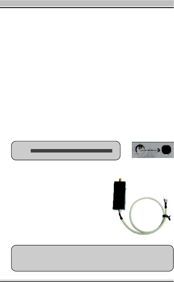
STEP 1
Unfasten the screws on the back panel and remove the case.
STEP 2
Use a 6mm screwdriver to puncture the perforated hole on the back
panel from the outs ide in. Once the screwdriver can pass through
the hole, carefully snap the metal tag off.
Note : If the cover still does not detach, carefully
of the chassis.
Note : The installation process of XPC 802.11b/g Wireless Kit will
be different for each XPC model and dependent on each XPC
design. Please refer to the following installation instructions for
your XPC model.
STEP 3
Take out the XPC 802.11b/g
Wireless Kit.
4
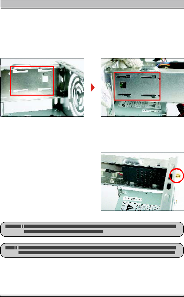
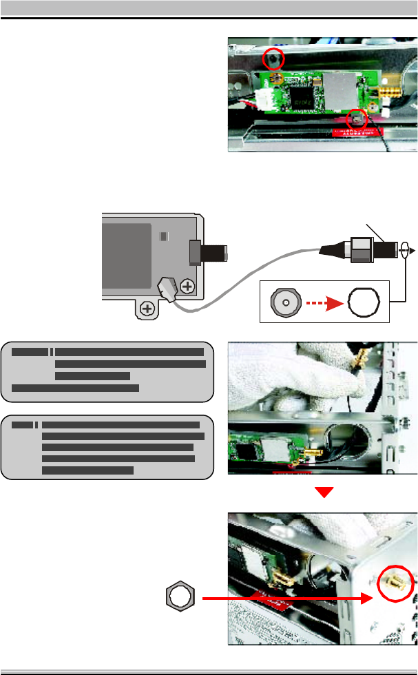
For P series
STEP 4-1
Install the XPC 802.11b/g Wireless Kit to the four attachment points
as shown below.
STEP 4-2
Install the antenna cable connector through the side reserve hole into the
back chassis.
Refer to Step5 (Page10).
5
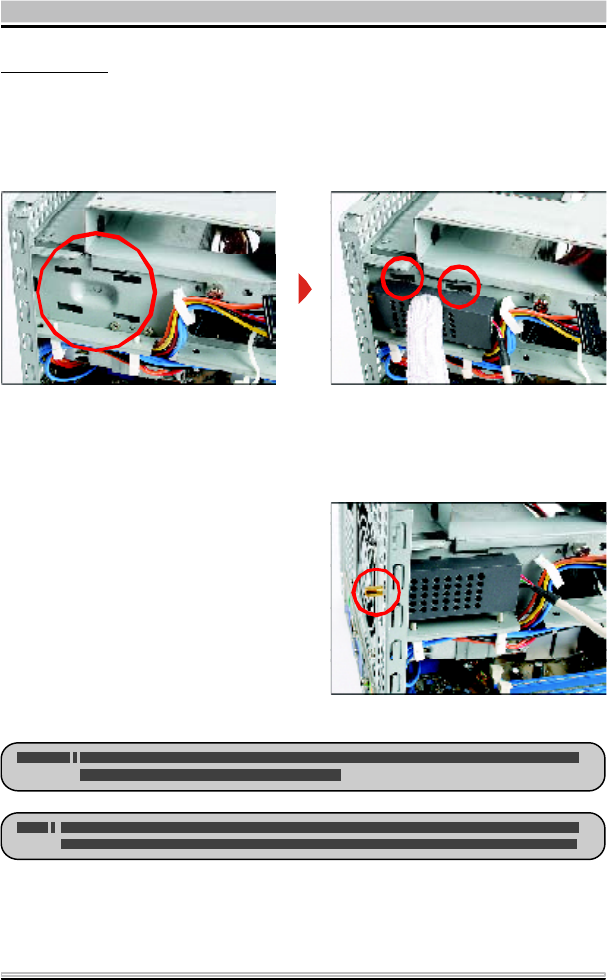
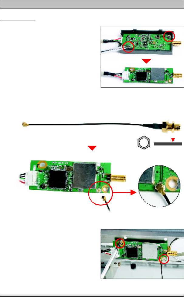
For i series
STEP 4-1
Install the XPC 802.11b/g Wireless Kit to the four attachment points
as shown below.
STEP 4-2
Install the antenna cable connector through the side reserve hole into the
back chassis.
Refer to Step5 (Page10).

6
For G,G2,G4,G5 series
STEP 4-1
Unscrew the two XPC
802.11b/g Wireless Kit’s
screws and remove the
module cover.
STEP 4-2
Take out the Antenna cable connector and remove the loc k, then
install it to the XPC 802.11b/g Wireless Kit.
STEP 4-3
Take out the chassis and fasten the XPC 802.11b/g Wireless Kit to
the chassis with the two screws.
7
STEP 4-4
Screw the XPC 802.11b/g
Wireless Kit to the two
holes on the upside of the
chassis arm, near the
rear of the XPC.
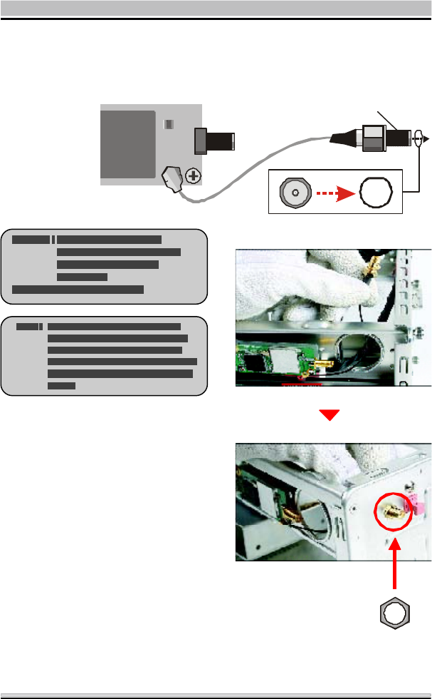
STEP 4-6
Use a lock to secure the
antenna from the outside.
Refer to Step5 (Page10).
STEP 4-5
Install the antenna cable connector through the side reserve hole into the
back chassis.
Antenna cable connector
8
For K series
STEP 4-1
Unscrew the two XPC
802.11b/g Wireless Kit’s
screws and remove the
module cover.
STEP 4-2
Take out the Antenna cable connector and remove the loc k, then
install it to the XPC 802.11b/g Wireless Kit.
STEP 4-3
Screw the XPC 802.11b/g
Wireless Kit to the two
holes on the upside of the
chassis arm, near the rear
of the XPC.
9
STEP 4-5
Use a lock to secure the
antenna from the outside.
Refer to Step5 (Page10).
STEP 4-4
Install the antenna cable connector through the side reserve hole into the
back chassis.
Antenna cable connector
10
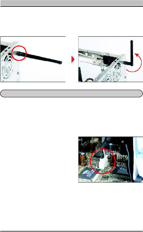
STEP 5
Screw the antenna onto the exposed thread. Set the antenna to
vertical for good reception.
Note : Make sure all the connectors are aligned in the correct direction.
STEP 6
Connect the signal cable from the XPC 802.11b/g Wireles s Kit to
the 5-pin USB header located on the motherboard. Double check
all connections before continuing.
STEP 7
Attach the case and fasten the thumbscrews to complete the
hardware installation.
11
2.2 Software Installation
Step 1: Install the Driver & Utility
For Windows 98, 2000, ME and XP users
1. Exit all Windows programs. Insert the included CD-ROM into
your computer. The CD-ROM will run automatically.
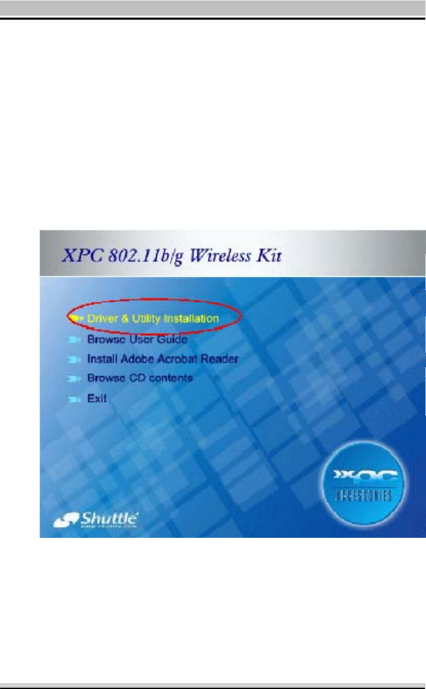
2. When the Main Menu screen appears, click “Driver & Utility
Installation” to continue.
12
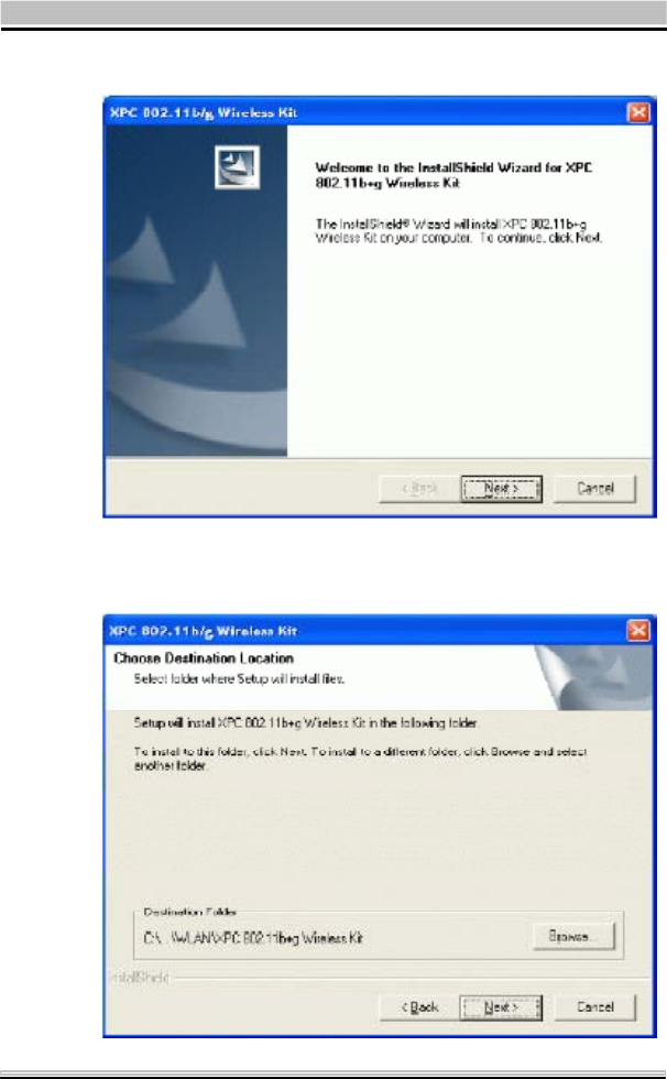
3. When the Welcome screen appears, click Next to continue.
4. The installation program will start running automatically.
Follow the on-screen instruction to proceed.
13
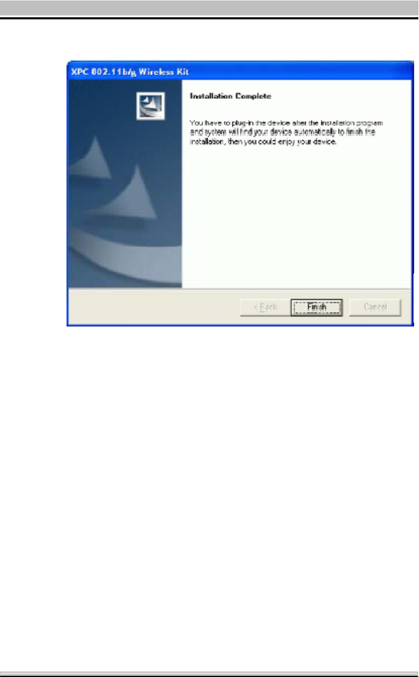
5. Click Finish to complete the software installation.
14
2.3 Network Connection
Once the device driver is well installed, a network setting de-
scribed in the following should be also established.
In Windows 98SE/ME
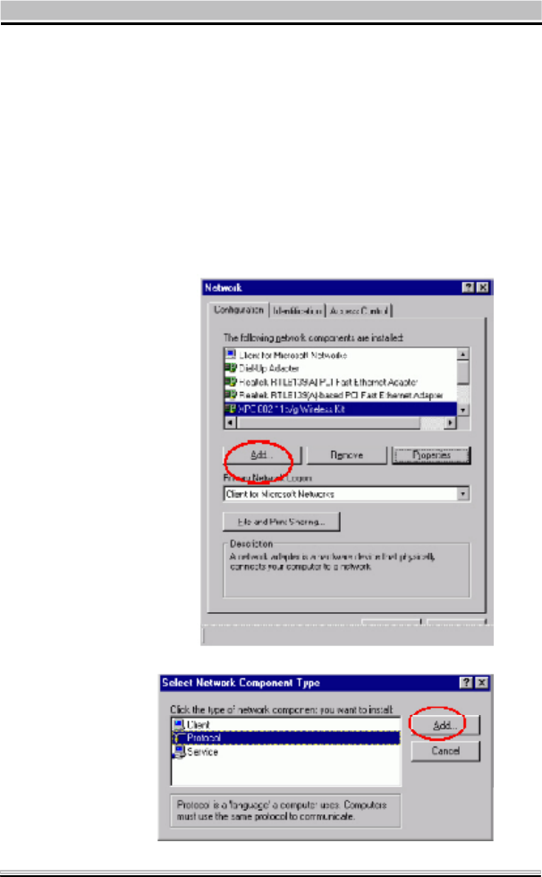
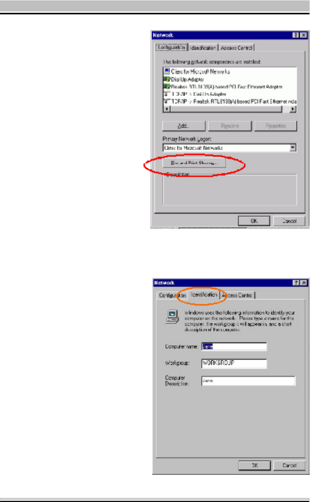
1. Go to Start ÆSettings ÆControl Panel ÆNetwork.
2. Make sure that all the required components are installed.
If any components are missing, click on the Add button to
add them in.
15
4. Click the Identification tab. Make up a name that is unique
from the other computers' names on the network.
Typethenameof
your workgroup,
which should be
thesameusedby
all of the other PCs
on the network.
3. For making your
computer visible
on the network,
enable the File
and Print Sharing.
16
6. When finished, restart your computer to activate the new
device. In Windows 2000/XP.
1. In Windows 2000
Go to Start ÆSettings ÆControl Panel ÆNetwork and
Dial-up Connections ÆLocal Area Connection Æ
Properties.
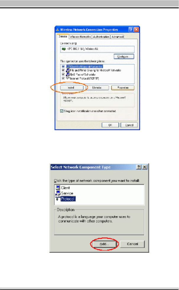
1. In Windows XP
Go to Start a Control Panel ÆNetwork and Internet
Connections ÆNetwork Connection ÆWireless Network
Connection Enabled USB W ireless Network Adapter.
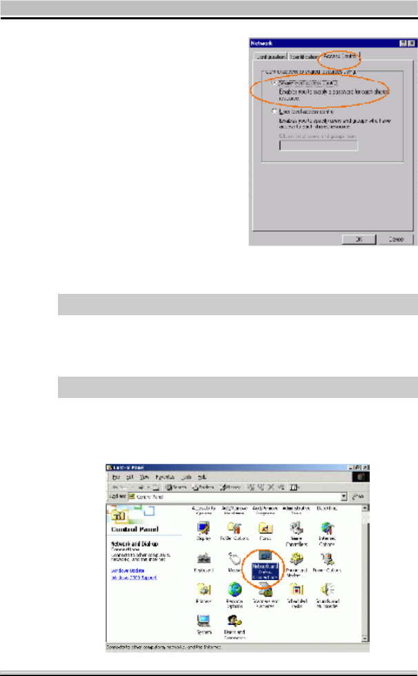
5. Click the Access Control
tab. Make sure that “Share-
level access control” is
selected. If connecting to a
Netware server, share level
canbesetto“User-level
access control.”
17
2. Make sure that all the required components are installed.
3. If any components are missing, click on the Install... button
to select the Client/Service/Protocol required. After se-
lecting the component you need, click Add... to add it in.
4. For making your computer visible on the network, make sure
you have installed File and Printer Sharing for Microsoft
Networks.
18
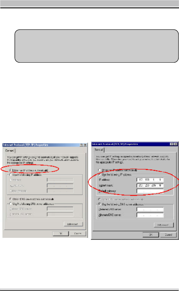
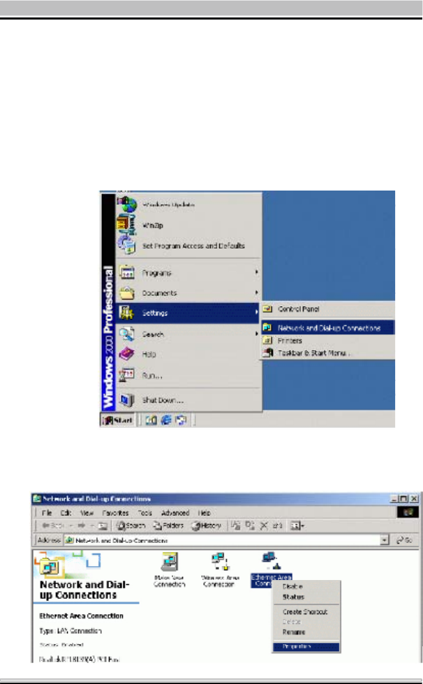
2.4 IP Address
Note: When ass igning IP Addresses to the computers on the network,
remember to have the IP address for each computer set on the same
subnet mask. If yo ur Broadb and Router us e DHCP tec hnology,
however, it won¡¦t be necessary for you to assign Static IP Address
for your computer.
1. To configure a dynamic IP address (i.e. if your broadband Router
has the DHCP technology), check the Obtain an IP Address
Automatically option.
2. To configure a fixed IP address (if you broadband Router is not
DHCP supported, or when you need to assign a static IP
address), check the Use the following IP address option. Then,
enter an IP address into the empty field, for example, enter 192.
168.1.1 in the IP address field, and 255.255.255.0 for the Subnet
Mask.
19
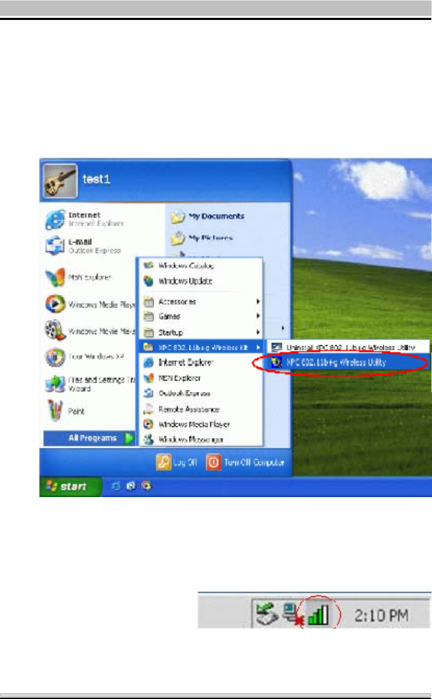
After the Wireles s adapter has been successfully installed, users
can use the included Configuration Utility to set their preference.
Go to Start Æ(All) Program ÆXPC 802.11b+g Wireless Kit
ÆXPC 802.11b+g USB Wireless Utility
For Windows 2000/XP, the Configuration Utility icon will also ap-
pear in the taskbar. You can open the Configuration Utility by click-
ing the icon.
2.5 Configuration Utility
20
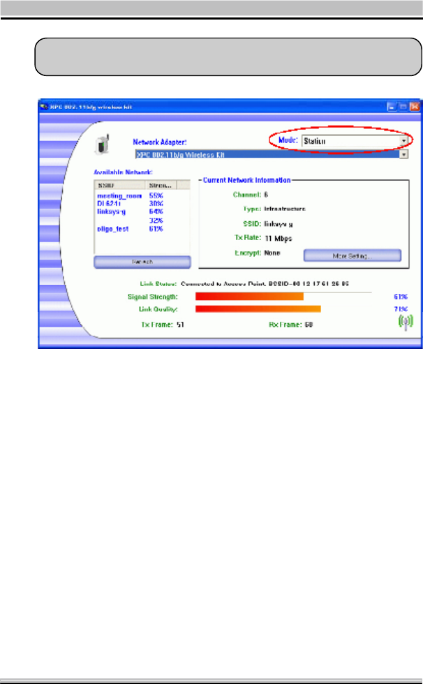
Note: The re will b e two modes - St atio n and Acce ss Point for you to
switch, you can select the mode you need from the pull-down menu.
21
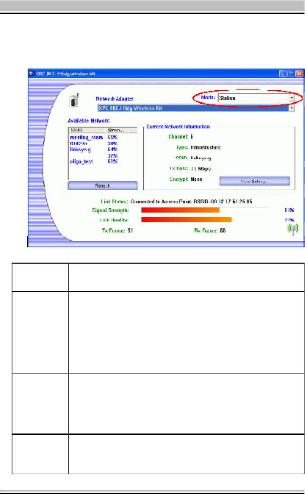
2.6 Station
Select Station mode, and you will see the following figure.
Channel Shows the selected channel that is currently in use. (There
are 14 channels available, depending on the country.)
Type
The infrastructure is intended for the connection between
wireless network cards and an Access Point. With the
wireless adapter, you can connect wireless LAN to a wired
global network via an Access Point. The Ad-hoc lets you set
a small wireless workgroup easily and quickly. Equipped
with the wireless adapter, you can share files and printers
between each PC and laptop.
SSID
The SSID is the unique name shared among all points in
your wireless network. The name must be identical for all
devices and points attempting to connect to the same
network. It shows the current SSID setting of the Wireless
USB Adapter.
Tx Rate Click the down arrow T to select the Tx Rate from Auto, 1,
2, 5.5, 11, 6, 9, 12, 18, 24, 36, 48, 54 Mbps, you can select
up to 54 Mbps.
22
Encrypt WEP is a data privacy mechanism based on a 64-bit
/128-bit /256-bit shared key algorithm.
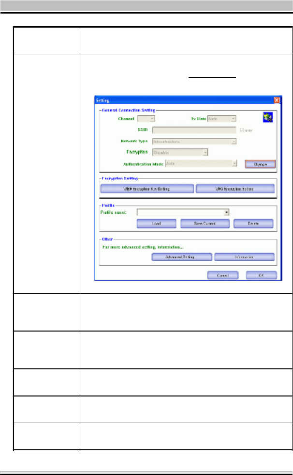
More Setting...
Click the More Setting button to configure, see the
following figure (Refer to the More Setting part on the
next page for more information about this figure):
Link Status Displays the information about the status of the
communication between the Wireless USB Adapter and
the Access Point.
Signal Strength Displays the signal strength of the connection between
the Wireless USB Adapter and the Access Point it
connects.
Link Quality Displays the link quality of the connection between the
Wireless USB Adapter and the Access Point it connects.
Tx Frame The quantities for the wireless network card transmit.
(Frame: The unit of packet)
Rx Frame The quantities for the wireless network card receive.
(Frame: The unit of packet)

23
Channel The Channel will change automatically according to
APs setting.
Tx Rate Click the down T arrow to select the Tx Rate from
Auto, 1, 2, 5.5, 11, 6, 9, 12, 18, 24, 36, 48, 54 Mbps,
you can select up to 54 Mbps.
SSID
The SSID is the unique name shared among all points
in your wireless network. The name must be identical
for all devices and points attempting to connect to the
same network.
Any
You may select to have SSID by choosing any, the SSID
will be obtained automatically from whichever Access
Point with the optimal signal for this device. If any is
left unchecked, it means you will have to enter the SSID
manually.
Network Type
The infrastructure is intended for the connection
between wireless network cards and an Access Point.
With the wireless adapter, you can connect wireless
LAN to a wired global network via an Access Point.
The Ad-hoc lets you set a small wireless workgroup
easily and quickly. Equipped with the wireless adapter,
you can share files and printers between each PC and
laptop.
Encryption
You can only set your Security preference when
Change is selected and then all fields are active for
change. To save settings, press Apply when you are
done with the settings. Select from the pull-down menu,
there are four options including Disable, WEP, TKIP
and AES.
Authentication
Mode
You can select the Authentication Mode from the pull-
down men, including Auto, Open System, Shared Key,
WPA and WPA PSK.
More Setting
24
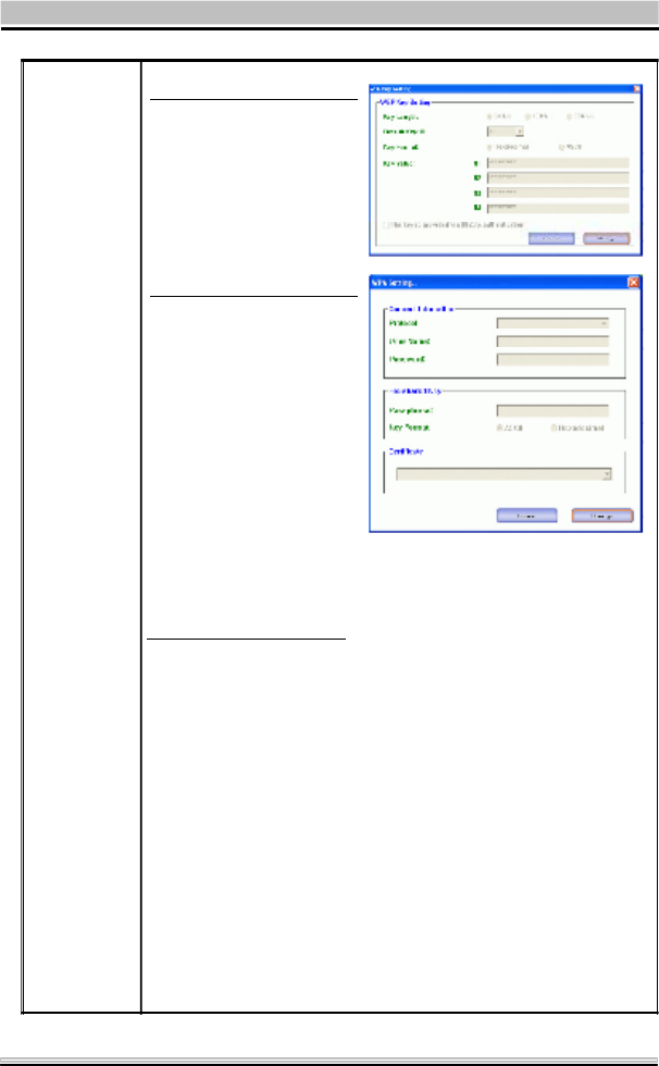
Encryption
Setting
You can only set your Security preference when "Change" is
selected and then all fields are active for change. To save
settings, press "Apply" when you are done with the settings.
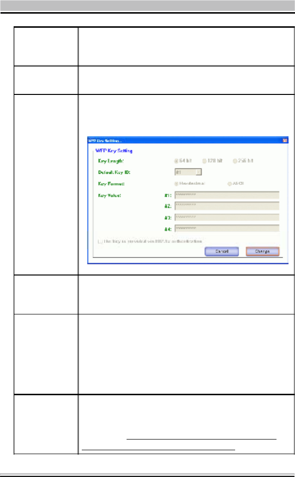
WEP Encryption Setting.
Key length : 64 (bit), 128 (bit) or 256 (bit).
Default Key ID : You can set your default key ID at #1~#4.
Key Format : Select Hexadecimal if you are using
hexadecimal numbers (0-9, or A-F).
Select ASCII if you are using ASCII characters (case-sensitive).
10 hexadecimal digits or 5 ASCII characters are needed if
64-bit WEP is used; 26 hexadecimal digits or 13 ASCII
characters are needed if 128-bitWEP is used; 58
hexadecimal digits or 29 ASCII characters are needed if 256-
bitWEP is used.
Key Value (#1~#4) : This setting is the configuration key
used in access-ing the wireless network via WEP encryption.
You can speci-fy up to 4 different keys to encrypt or decrypt
wireless data.
WEP Encryption Setting
WPA Encryption Setting

25
The Key is provided via 802.1x authenticationG :
Please query your network manager about the currently used
security protocol, if 802.1x authentication is currently used,
then you can check this item to enable 802.1x security
protocol. The key value will be configured automatically,
just click "Apply" to take effect.
WPA Encryption Setting
Protocol :
This panel enables you to select an authentication protocol.
User Name :
Type in the user name assigned to the certificate.
Password : This panel is available when EAP-TLS is not
selected (either MSCHAP V2 over PEAP is selected with WEP
or LEAP is selected for CCX). This panel enables you to enter
a login name and password or request that the driver prompt
for them when you connect to a network.
Passphrase : Enter the key that you are sharing with the
network for the WLAN connection.
Key Format : Select Hex if you are using hexadecimal
numbers (0-9, or A-F).
Select ASCII if you are using ASCII characters.
Certificate : Please query your network manager about the
certificate, select the same certificate as the certification
server.
Load You may select already saved file from the "Profile name"
list, and then press "Load ". The setting status will then be
restored.
Save
Current You may save current setting to profile and add one new
item in "Profile name".
Delete Delete the files in the "Profile name".
26
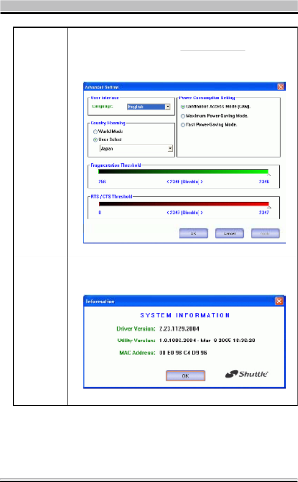
Advanced
Setting
Click the Advanced Setting button to configure the
following figure ( Refer to the Advanced Setting part
on the next page to see more information about the
Advanced Setting ) :
Information
Click the Information button to show the Driver Version,
Utility Version and MAC Address of the system.
27
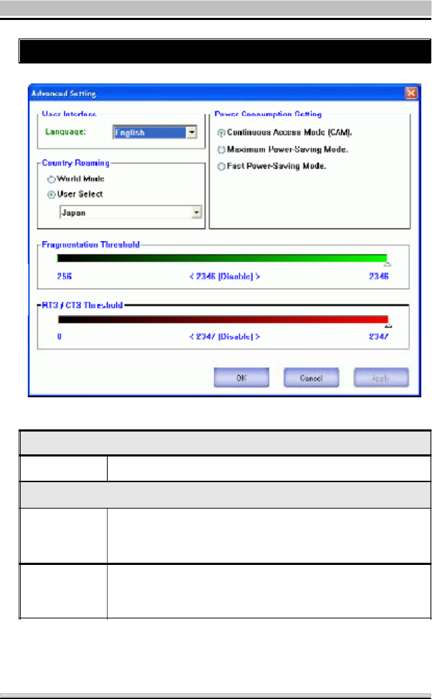
Advanced Setting
User Interface
Language Select your preferred Language.
Power Consumption Setting
Continuous
Access Mode
(CAM)
When this mode is selected, the power supply will be
normally provided even when there is no throughput.
Maximum
Power-Saving
Mode
When this mode is selected, this device will stay in power
saving mode even when there is high volume of
throughput.

28
Fast Power-
Saving Mode
When this mode is selected, the power mode will switch
between CAM and Maximum Power-Saving Mode
depending on the volume of throughput.
The device driver checks the total bytes (only data frame)
every 4 seconds to decide the power mode. If the total
bytes sent exceed 10k bytes, the device driver will
choose "CAM". If the total bytes are less than 10k bytes,
however, the device driver will choose "Maximum
Power-Saving Mode".
Country Roaming
World Mode This function is only enabled and effective with 802.11d
standard.
User Select Enable this function to select the country you are now
locating.
Fragmentation
Threshold
The mechanism of Fragmentation Threshold is used to
improve the efficiency when high traffic flows along in
the wireless network. If your 802. Wireless LAN Adapter
often transmit large files in wireless network, you can
enter new Fragment Threshold value to split the packet.
The value can be set from 256 to 2346. The default
value is 2346.
RTS/CTS
Threshold
RTS/CTS Threshold is a mechanism implemented to
prevent the "Hidden Node" problem. If the "Hidden
Node" problem is an issue, users have to specify the
packet size. The RTS/CTS mechanism will be activated
if the data size exceeds the value you set. The default
value is 2347. This value should remain at its default
setting of 2347. Should you encounter inconsistent
data flow, only minor modifications of this value are
recommended.
29
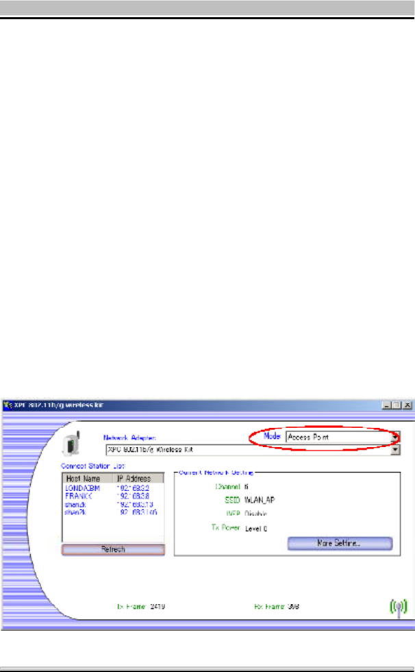
2.7 Access Point
In access point mode, the XPC 802.11b/g Wireless Kit will func-
tion as an access point. This al lows you to set up your wireless
networks without using a dedicat ed AP device. Up to 16 wireless
stations can associate to the XPC 802.11b/g Wireless Kit.
To use the XPC 802.11b/g Wireless Kit to bridge your wired and
wireless network, the following requirements must be met :
1. The XPC 802.11b/g Wireless Kit must be installed on a com-
puter connected to the wired network.
2. Eit her configu re net work sharing (refer to the append ix for an
example) or bridge the two interfaces (wireless and wired) on the
computer.
3. Set the wireless station’s IP address to be in the same subnet
as the computer in which the XPC 802.11b/g Wireless Kit is
installed. Refer to Configuring the Wireless Station Comp-
uter.
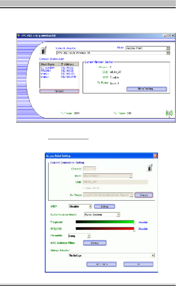
Select the Acce ss P oi n t mode, and you will see the following figure.
30
Network
Adapter
You can select the network adapter from the pull-down
menu, it shows the device itself ( the XPC 802.11b/g
Wireless Kit ) and also shows the devices supported by
the XPC 802.11b/g Wireless Kit.
Connection
Station List Show the currently connected devices and IP addresses.
Channel Shows the selected channel that is currently in use. ( There
are 14 channels available, depending on the country.)
SSID
The SSID is the unique name shared among all points in your
wireless network. The name must be identical for all devices
and points attempting to connect to the same network. It
shows the current SSID setting of the Wireless USB Adapter.
WEP The WEP function here has been disabled. If you want to
change to Enabled, click More Setting... to configure
Tx Power The Tx power here is configured as Level 0, to change the Tx
power, click More Setting... to configure.
More
Setting...
Click the More Setting... button and the following figure will
appear for you to configure ( Refer to the More Setting... part
on the next page for more information about this figure. )
31
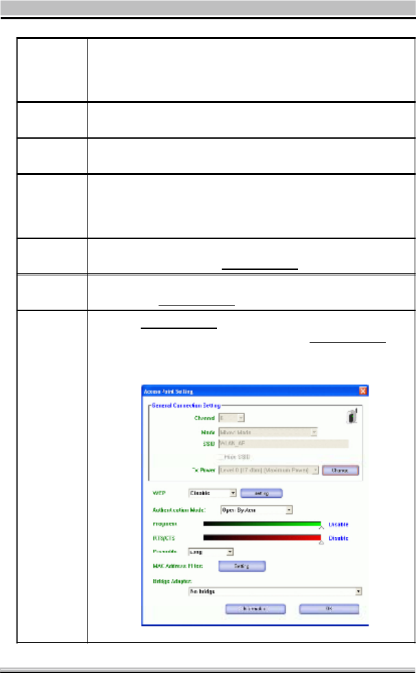
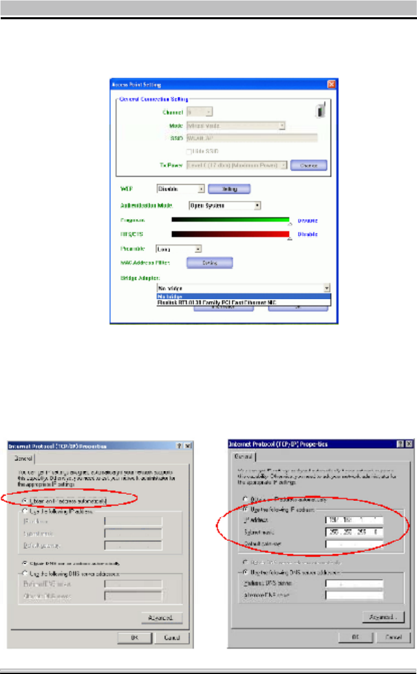
More Setting
Tx Frame The quantities for the wireless network card transmit.
( Frame : The unit of packet )
Rx Frame The quantities for the wireless network card receive.
( Frame : The unit of packet )
Channel Shows the selected channel that is currently in use.
(There are 14 channels available, depending on the
country.)
Mode Select Mixed Mode or 802.11b only,802.11b/g only
standard Mode (If you choose this option the device
will automatically convert the suitable standard ).
SSID
The SSID is the unique name shared among all points
in your wireless network. The name must be identical
for all devices and points attempting to connect to the
same network. It shows the current SSID setting of the
Wireless USB Adapter.
32
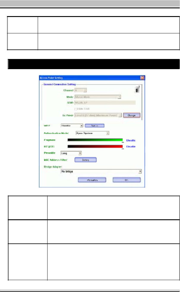
Tx Power Select the Tx power from the pull-down menu, there
are four levels in cluding Level 1, Level 2, Level 3
(Minimum).
Change or
Apply Click "Change" to set the General Connection Setting.
After Completing the setting Click "Apply".
WEP
You can select to Enable or Disable the WEP function by
selecting from the pull-down men. Click Setting and the
following figure will appear.
Authentication
Mode
Select the Authentication mode from the pull-down
menu, there are two modes for you to choose,
Open System and Shared Key.
Fragment
The mechanism of Fragmentation Threshold is used to
improve the efficiency when high traffic flows along in
the wireless network. If your 802. Wireless LAN Adapter
often transmit large files in wireless network, you can
enter new Fragment Threshold value to split the packet.
The value can be set from 256 to 2346. The default
value is 2346.
RTS/CTS
RTS/CTS Threshold is a mechanism implemented to
prevent the "Hidden Node" problem. If the "Hidden
Node" problem is an issue, users have to specify the
packet size. The RTS/CTS mechanism will be activated
if the data size exceeds the value you set.
33
The default value is 2347. This value should remain at
its default setting of 2347. Should you encounter
inconsistent data flow, only minor modifications of this
value are recommended.
Preamble
A preamble is a signal used in wireless environment
to synchronize the transmitting timing including
Synchronization and Start frame delimiter. Select from
the pull-down menu to change the Preamble type into
Long or Short.
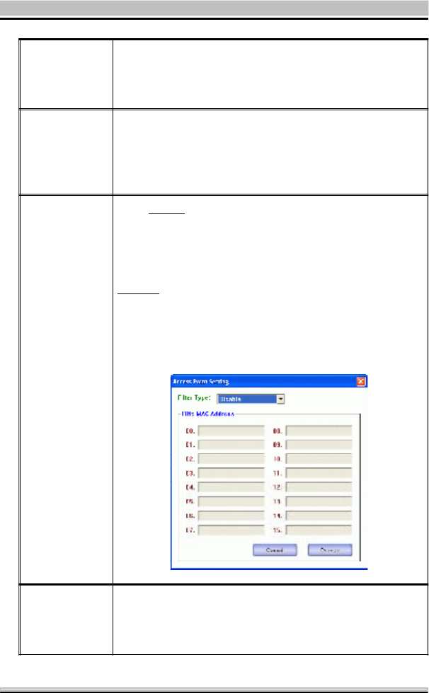
MAC Address
Filter Click Setting and you will see the following figure. You
can select the Filter Type from the pull-down menu.
Disable : Select to disable the filter function.
Accept : You can type in 15 MAC addresses by clicking
Change. If you select Accept, then the MAC address(es)
you type in will be connected to the AP.
Reject : You can type in 15 MAC addresses by clicking
Change. If you select Reject, then the MAC address(es)
you type in will not be connected to the AP
Bridge
Adapter
The stations will not be allowed to connect to the
internet if you select No bridge. The stations will be
allowed to connect to the internet if you select the
device listed in the pull-down menu.

34
3. Appendix
3.1 SoftAP Configuration
Setup Requirement :
To bridge your wired and wireless network using XPC 802.11b+g
Wireless Kit, the following must be met :
1. Install the XPC 802.11b+g Wireless Kit on the LAN-connected
computer.
2. The Soft Access Point should be connected to a network switch,
hub or a Broadband Router. Use a standard Category 5 UTP
Ethernet cable with an RJ-45 connector to connect the Soft Ac-
cess Point to one of router, hub, or switch.
3. The computer that you are installing the wireless card into has
an Ethernet connection, and is connected to a LAN with a DHCP
server. SoftAP Configuration :
35
1. Selec t the Access Point m ode, and y ou will see the following
screen.
2. Click the More Setting. .. button and the following figure will
appear for you to configure.
36
3. Select the wired Network A dapter that has already installed in
the XPC from the pull-down menu.
4. If the network connect ed t o the wired LA N card has a DHCP
server, you just need to configure the wireless station as aDHCP
client (select Obtain an IP addressautomatically). If the net
work does not have a DHCP server, you must assign a fixed IP
to the wired XPC (select Use the following IP address).
37
This example uses the network s haring feature in Windows 2000/
XP to bridge the wired and wireless network when you set the XPC
802.11b+g Wireless Kit in access point (AP) mode
Setups may vary depending on your Windows version. Yo u m a y
need to install additional software in Windows 98/ME.
Step1 Go to Start ÆSetti ngs ÆNetwork a nd Dia l-up Con-
nections (in Windows XP, go to Start ÆControl Panel
and double-click Network Connections).
Step2 Right-click on the icon for your Wired Ethernet Adapter
and click Properties.
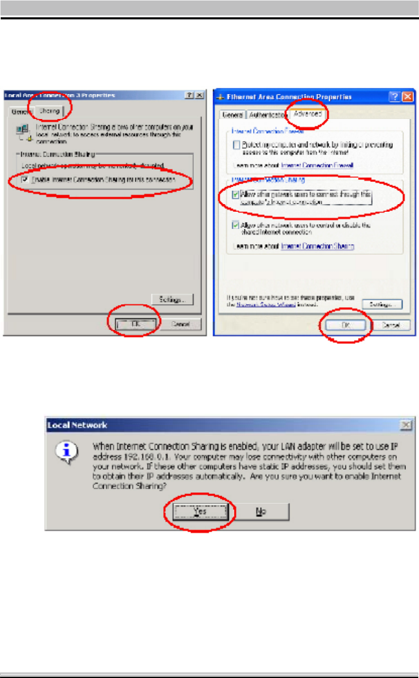
38
Step3 Click the Sharing tab and select Enable Internet Con-
nection Sharing for this connection. Click OK.
Step4 When the following screen appears, click Ye s.
Configuring the Wireless Station Computer
Please refer to the Network Connection in the previous section to
set up the wireless station computer(s) IP address.

39
3.2 Specifications
Product Name XPC 802.11b/g Wireless Kit
Model Name PN18
Host Interface Standard USB2.0 Interface
Dimensions 74(W)x23(L)x7.4(H)mm
Weight 5g
Frequency Band 2.4~2.4835GHz(subject to local regulations)
Operating
Voltage 5V
Current
Consumption Tx: 350mA/ Rx:250mA / Standby: 10mA
Spreading OFDM(Orthogonal Frequency Division Multiplexing)
Data Rate 1Mbps, 2Mbps, 5.5Mbps, 6Mbps, 9Mbps, 11Mbps, 12Mbps,
18Mbps, 24Mbps,36Mbps, 48Mbps, 54Mbps,
Transmit Power 11g: 13.5dBm / 11b: 16.5dBm
Receive
Sensitivity 11Mbps @-82dBm Typical / 54Mbps @-70dBm Typical
Modulation 11 Ck(802.11b), BPSK, QPSK, 16-QAM, 64QAM(802.11b/g)
Security 64/128/256 bit WEP Encrytion, WPA Encryption
Antenna HIROSE U.FL-R-SMT(10)
Supplied Driver Windows 98SE/ME/2000/XP
Standards IEEE 802.11b/g
Media Access
protocol CSMA/CA with ACK
Temperature
Range 0~60oC(Operating), -20~70oC(storage)
Humidity Max. 95% Non-condensing
Operating Range Open Space: Up to 400m
Management
Utility Link Configuration for network join and diagnostics
EMC certification FCC,CE, Japan RF
Warranty 1 year
22
20.5
Federal Communication Commission Interference Statement
This equipment has been tested and found to comply with the limits for a
Class B digital device, pursuant to Part 15 of the FCC Rules. These limits
are designed to provide reasonable protection against harmful interference in
a residential installation. This equipment generates, uses and can radiate
radio frequency energy and, if not installed and used in accordance with the
instructions, may cause harmful interference to radio communications.
However, there is no guarantee that interference will not occur in a particular
installation. If this equipment does cause harmful interference to radio or
television reception, which can be determined by turning the equipment off
and on, the user is encouraged to try to correct the interference by one of the
following measures:
- Reorient or relocate the receiving antenna.
- Increase the separation between the equipment and receiver.
- Connect the equipment into an outlet on a circuit different from that
to which the receiver is connected.
- Consult the dealer or an experienced radio/TV technician for help.
This device complies with Part 15 of the FCC Rules. Operation is subject to
the following two conditions: (1) This device may not cause harmful
interference, and (2) this device must accept any interference received,
including interference that may cause undesired operation.
FCC Caution: Any changes or modifications not expressly approved by the
party responsible for compliance could void the user's authority to operate this
equipment.
IMPORTANT NOTE:
FCC Radiation Exposure Statement:
This equipment complies with FCC radiation exposure limits set forth for an
uncontrolled environment. This equipment should be installed and operated
with minimum distance 20cm between the radiator & your body.
This transmitter must not be co-located or operating in conjunction with any
other antenna or transmitter.
SHUTTLE INC. declared that PN18 is limited in CH1~11 from 2412 to 2462
MHz by specified firmware controlled in USA.