Shyam Telecom HB-20-S8 Home Booster HB-20-S8 User Manual
Shyam Telecom Inc. Home Booster HB-20-S8 Users Manual
Users Manual
File Doc. No. Date Version Page
HB-20 5700 9004 054 Nov,06 2.0 1
Next Generation
Signal Enhancement
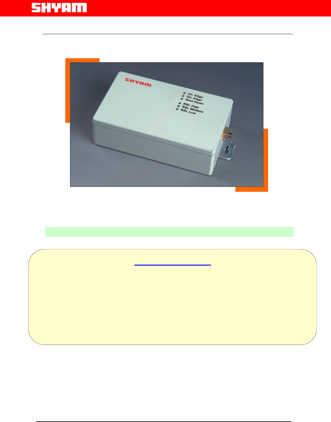
HB-20 Series Booster
Model No- : HB-20-S8
O
OP
PE
ER
RA
AT
TI
IO
ON
N
A
AN
ND
D
I
IN
NS
ST
TA
AL
LL
LA
AT
TI
IO
ON
N
M
MA
AN
NU
UA
AL
L
SHYAM Telecom Inc.
6,Kilmer Road, Suite D, Edison ,New Jersey 08817 ,USA
Office :- +1 732 9851324 Fax :- +1 732 907 1023
Email:repeater@shyamtelecom.com
H
HB
B-
-2
20
0
Home Booster fo
r
SMR 800
(
iDEN
)
5700 9004 054 REV. 2.0 Nov 2006
Proprietary Information
The information contained herein is proprietary to Shyam Telecom Limited.
Unauthorized access, copy and replication is prohibited. Use or disclosure of this
document or the information contained herein, for any purpose other than that for
which it was furnished is not permitted. This document must not be copied in
whole or part by any means or it shall not be disclosed or divulged to any third
Party without the prior written consent of Shyam Telecom Limited.

File Doc. No. Date Version Page
HB-20 5700 9004 054 Nov,06 2.0 2
Next Generation
Signal Enhancement
Congratulation! You have acquired a world-class repeater. This system has
been designed to operate on the latest digital mobile communication technology
so as to guarantee you enhanced voice clarity each time, every time. It is, as you
will soon find yourself, the ultimate in reliability and quality. This has an elegant
design as SHYAM has always striven to give customer what he wants, at a price
no one can match, and keep him happy after the sale. A result, ensured by an
annual R&D budget of US$ 5 million and the best R&D center in its category
award, by department of Scientific & Industrial Research (DSIR), Government of
India.
Shyam today is US$ 50 million group, number one for Outdoor & In-Building
solution in India, one of the world’s most growing mobile markets.
True to the family to which this system belongs, is uniquely designed to render
crystal clear sound and error free data for a long, very long time. We would
request to go through this easy to understand HB-20 manual to know your
system better.
Regards
Yours Sincerely
(General Manager)

File Doc. No. Date Version Page
HB-20 5700 9004 054 Nov,06 2.0 3
Next Generation
Signal Enhancement
WARRANTY:
System HB-20 is guaranteed against manufacturing defects of parts and
components inside the system for a period as per warranty clause of purchase
order. Should a defect arise in this system during the period of warranty, Shyam
Telecom Ltd., as the seller undertakes to get the system repaired free of charge,
through its authorized service center. To carry out repair the cost of
transportation have to be borne by the customer.
This warranty is not valid in one or more than one of the following event(s) /
circumstances:
a. Defect caused by negligence, improper use or accident to any part of the
system.
b. If serial number of system is tempered with.
c. If repair / service / modification was done by an unauthorized person.
d. Defects arising out of circumstances beyond control like lightning,
abnormal voltage, act of God etc.
e. If warranty paper is not completed and signed on delivery of the system
by the SHYAM authorized person.
f. The warranty is not applicable to second or subsequent buyer.
g. Please note that the warrant does not extend to any accessory (including
antenna) if any, supplied with the system.
h. The warranty is subject to the jurisdiction of the civil court of Delhi, India,
only.
Our obligation under this Warranty is limited to prompt repair or replacement of
the product, without charge, when the product is returned to the factory.
File Doc. No. Date Version Page
HB-20 5700 9004 054 Nov,06 2.0 4
Next Generation
Signal Enhancement
The description and characteristics given in this document are of informative significance only and
noncommittal. In fact, to keep up the high quality of our system, we reserve the right to make
change or improvement in this manual without prior notice.
Shyam Telecom evaluates if the product can be repaired or if it is necessary to
replace the unit.
In case the product is out of warranty, the customer will be informed about the
cost for repairing or replacing the unit. The service will be provided only after
receiving the customer’s authorization .Before returning the goods, the customer
should give prior notice to Shyam Telecom through normal return authorization
procedure.
Shyam Telecom aims to offer an excellent service. To do that we ask our
customer to enclose to the returned product an accompanying letter, including
the following information:
Refer to the serial label
N.B. Each product must be packaged with care before shipment.
Shyam Telecom will issue a check report, which is included in the packing
together with the product being returned. The customer will be informed about
any corrective actions suggested by quality assurance.
Company Name
Address
Contact Person
Invoice Number
Delivery Note
No. of pieces
Model*
Serial Number*
Lot*
Year*
Description of the failure
/ defect

File Doc. No. Date Version Page
HB-20 5700 9004 054 Nov,06 2.0 5
Next Generation
Signal Enhancement
Contents
SECTION 1.............................................................................................................6
1.1 Preamble .................................................................................................... 6
1.2 About the manual ....................................................................................... 6
1.3 Important Safety Information...................................................................... 6
SECTION 2.............................................................................................................8
2.1 Introduction: Booster Theory / Background ............................................... 8
SECTION 3.............................................................................................................9
3.1 Description of HB-20 Booster installation Kit ............................................. 9
3.2 List of Installation Kit ................................................................................ 10
SECTION 4...........................................................................................................11
4.1 System Design and Setup........................................................................ 11
SECTION 5...........................................................................................................12
5.1 Installing the HB-20.................................................................................. 12
5.2 Installation Tools ...................................................................................... 12
5.3 Installation Procedure: Do It Yourself ..................................................... 12
5.4 Power Startup / Alarm Checks / Coverage Testing ................................. 13
SECTION 6...........................................................................................................15
6.1 Display Details of HB-20 .......................................................................... 15
SECTION 7...........................................................................................................16
Annexure 1……................................................................................................... 16
Technical Specification: Boosters HB-20............................................................ 16
Annexure 2……................................................................................................... 18
Trouble shooting procedure HB-20.................................................................... 18

File Doc. No. Date Version Page
HB-20 5700 9004 054 Nov,06 2.0 6
Next Generation
Signal Enhancement
SECTION 1
1.1 Preamble
In cellular systems boosters / repeaters are used, to enhance the coverage of a
Base station in a region where, due to topological conditions, poor field strengths
disable communication. SHYAM is a leading manufacturer of boosters /
repeaters. These boosters / repeaters provide excellent electrical characteristics,
are lightweight and easy to install.
Any intervention has to be performed by authorized persons only. If you need
technical assistance, please contact at the following address:
SHYAM Telecom Inc.
6,Kilmer Road, Suite D, Edison ,New Jersey 08817 ,USA
Office :- +1 732 9851324 Fax :- +1 732 907 1023
Email:repeater@shyamtelecom.com
Under consideration of all references given in this manual, the repeater should be
taken into service without any complications and should operate trouble free for a
long time.
However we have country wide after sales support network to assist you if
required.
Please visit to our web site www.shyamtelecom.com for our country wide after
sales support offices.
1.2 About the manual
The “Installation and Operation manual” is intended to be used for SHYAM
HB-20 Booster installation. It contains the general guidelines for the field
engineers /technicians. Read carefully before starting the installation.
1.3 Important Safety Information
The HB-20 booster has been designed for maximum safety when installed and
operated according to the instructions in this manual. Refer to all safety
instructions as per the antenna installation instruction sheets.
File Doc. No. Date Version Page
HB-20 5700 9004 054 Nov,06 2.0 7
Next Generation
Signal Enhancement
Do not bypass any of the safety features with the equipment provided, nor
operate the system in an inappropriate environment.
WARNING! Installation of antennas near power lines is dangerous. For your
safety, follow all installation directions and keep safe distance from any
high voltage power lines that could result in shock or loss of life.
WARNING! This equipment complies with FCC & IC radiation exposure
limits set forth for an uncontrolled environment. This transmitter must not
be co-located or operating in conjunction with any other antenna or
transmitter. The signal booster with server antenna must be installed to
provide minimum 20 cm separation distance between the server antenna to
the body of user or near by person. The donor antenna used for this
transmitter must be fixed-mounted on outdoor permanent structures with a
separation distance of at least 1.5 meters from all persons during normal
operation.
Additional wiring required to install the HB-20 system should comply with national
or local governing Electrical Codes. Indoor RF coaxial cable installations should
comply with local Electrical Code requirements.
The HB-20 booster is designed for indoor application. The housing is not
waterproof, so please keep it away from water, rain and any chemical liquid.
Do discharge the static before you touch the connectors of the booster.
Do not open the module inside the booster unless you are authorized.
The power supply unit in the HB-20 booster is supplied from the mains (primary
AC power) that contains dangerous voltage level which will cause electric shock,
Please turn off the mains before you install / uninstall the booster.The primary AC
power should be in the range of AC100-240V, 50/60Hz. Booster will be damaged
if the primary AC power is out of the range.
The RF electric performance of the HB-20 booster conforms to ETSI
requirement of the inter modulation and spurious emission. It avoids the
interference problem.
File Doc. No. Date Version Page
HB-20 5700 9004 054 Nov,06 2.0 8
Next Generation
Signal Enhancement
SECTION 2
2.1 Introduction: Booster Theory / Background
In mobile cellular communication system, boosters provide the radio frequency
(RF) coverage to areas, which either lack signal, or the required signal strength is
inadequate for mobile phone performance. To the typical user, this translates to
the inability to place or receive mobile phone calls in or out of the area, and in
most cases will result in a dropped call while entering into the poor coverage
area. Insufficient wireless coverage can occur both indoors and outdoors, and
may include indoor areas such as office buildings, parking garages, apartment
buildings, shopping malls, and residential homes. Outdoor areas are degraded by
geographic topologies such as mountains, valleys, dense foliage and high rising
urban landscapes which can easily degrade or obstruct the cell site’s signal from
the mobile phone.
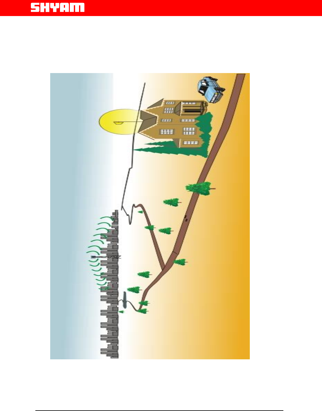
The weak coverage problem can be solved by installing an active booster
system, designed for use in a multitude of installation configurations. Booster
systems provide an effective solution by redirecting, filtering and amplifying the
available signal at the donor antenna, into the weak coverage area, through a
properly selected interior coverage antenna. The illumination of the weak
coverage area allows the user’s handset to operate as intended within the
building or weak coverage area, while maintaining the user’s call clarity .
Figure 1: Typical Booster/Coverage Configuration
Booster
Antenna
File Doc. No. Date Version Page
HB-20 5700 9004 054 Nov,06 2.0 9
Next Generation
Signal Enhancement
SECTION 3
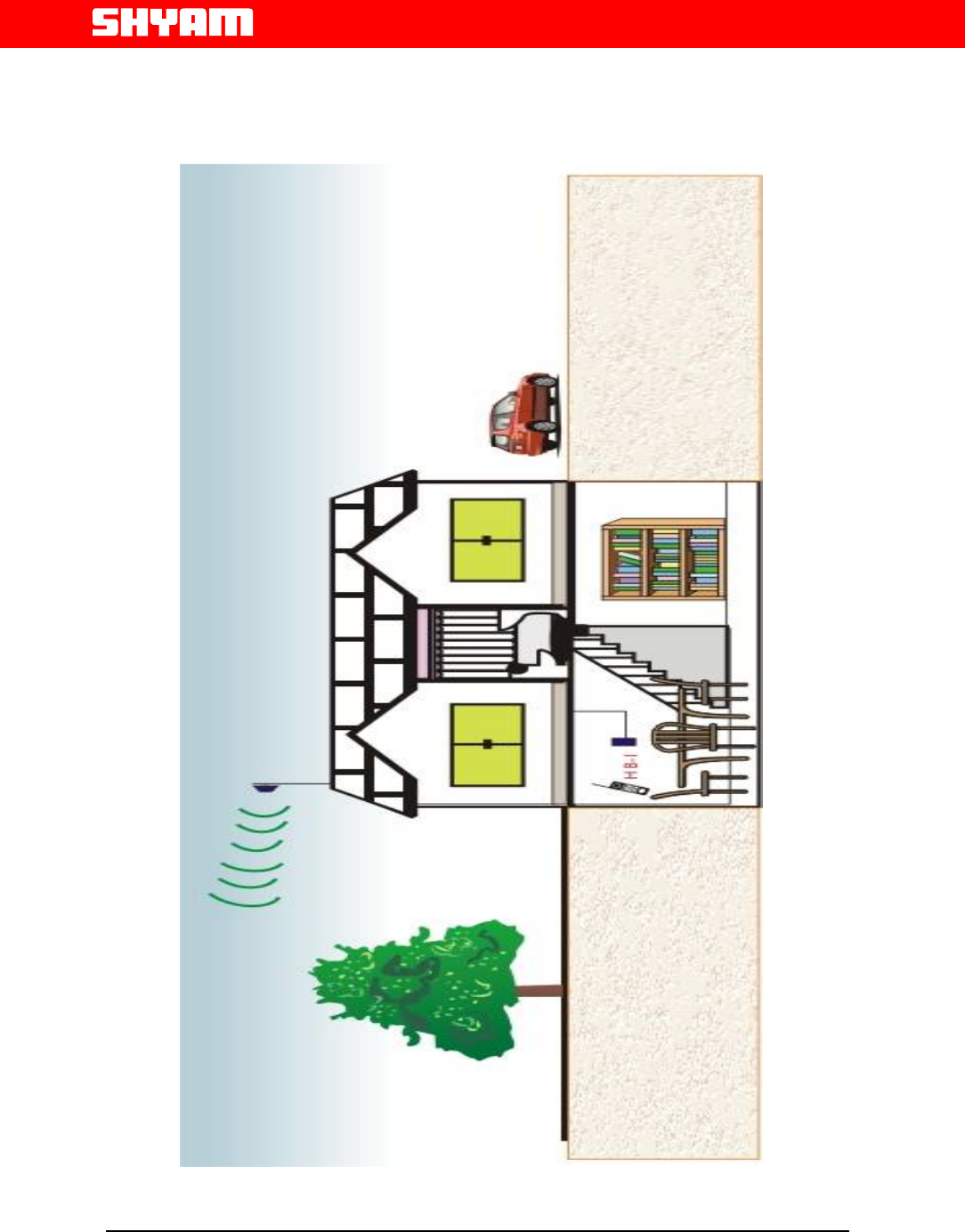
3.1 Description of HB-20 Booster installation Kit
The HB-20 booster system contains an automatic power control, bi-directional
amplifier (BDA) supplied along with a donor antenna (highly directive outdoor
antenna) and server antenna (indoor omni directional antenna), specifically
designed for interior configurations. The donor antenna must be pointed toward
the cell of the base station from where the signal is to be picked up and is usually
mounted on the exterior of the building so as to receive the maximum forward
signal level from the base station. The indoor antenna of HB-20 booster provides
RF signal in all directions downward and outward from the installation point.. A
adopter is supplied with HB-20, powered by universal 100-240 VAC mains
supply. A standard length of 10 mtr RF coaxial cable with connectors is supplied
to connect the donor antenna and HB-20 booster. Any other RF coaxial cable
length is also available optionally, on request.
.
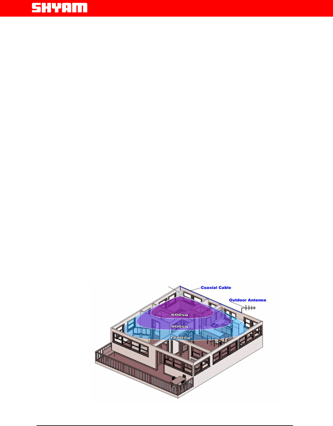
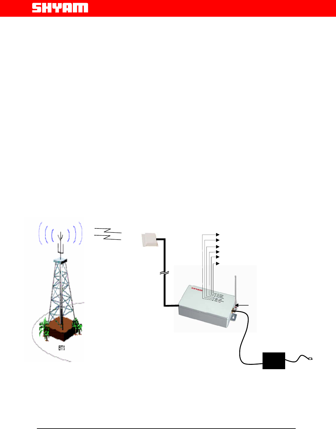
Figure 4.0 : Installation Diagram of Home Booster
Donor Antenna
Coaxial Cable
+9V DC
AC/DC
Adapter
Donor Antenna
Server Antenna
U/L Align
D/L Align
Shut Down
RSL Low
RSL Mid
RSL High

File Doc. No. Date Version Page
HB-20 5700 9004 054 Nov,06 2.0 10
Next Generation
Signal Enhancement
3.2 List of Installation Kit
1. Donor Antenna – Patch Antenna (Optional 7 dbi)
2. Server Antenna - Whip Antenna. (Optional 0 dbi )
3. RF coaxial cable with SMA to SMA (M) connector. (Optional)
4. Booster HB-20.
5. AC/DC Adapter (9VDC/2.0 Amp.).
6. Mounting Kit.
7. Installation and Operational Manual

File Doc. No. Date Version Page
HB-20 5700 9004 054 Nov,06 2.0 11
Next Generation
Signal Enhancement
SECTION 4
4.1 System Design and Setup
The HB-20 is designed to provide optimal coverage for areas of 500 Sq Meters
(5,000 sq. ft) to 1,000 Sq Meters (10,000 sq. ft). However, performance also
depends on the amount of in-building shadowing, and the available forward
signal level at the donor antenna. Typical coverage is usually planned for
relatively small areas such as large conference room or several adjacent rooms
in smaller office areas. Indoor coverage varies greatly due to the nature of
various building construction techniques and materials.
The system design is quite simple & straightforward. The signal from the base
station (of the selected Operator) is picked up, preferably on the rooftop.
The built in receive signal level indicator in HB-20 booster helps in aligning the
donor antenna towards the selected base station & it always shows the received
signal level from the base station. It is imperative to monitor the received signal
level from the base station, also called downlink signal. Downlink signal may
change if some high building, trees or any other obstruction comes in the way of
line of site (LOS) between the BTS & the Donor antenna. This may reduce the
downlink received signal level & will result in poor service.

File Doc. No. Date Version Page
HB-20 5700 9004 054 Nov,06 2.0 12
Next Generation
Signal Enhancement
SECTION 5
5.1 Installing the HB-20
Pre-installation considerations
1. Once the expected coverage area is determined, identify the installation
location for the donor antenna and HB-20 booster. Ensure that the donor
antenna has a direct line-of-site to the service provider’s base station.
2. HB-20 installation site location criterion
i. A cool, dry location, away from other heat generating appliances or
equipment.
ii. Accessibility to electric power point.
iii. Flat, structural mounting surface.
iv. Accommodation for the indoor antenna providing line-of-site coverage to
as much of the coverage area as possible.
5.2 Installation Tools
You will only need the standard wrenches/hammer/screwdrivers/pliers set
for installing the HB-20 booster and donor antenna.
5.3 Installation Procedure: Do It Yourself
To install HB-20 booster, follow the steps as mentioned below:
1. Locate weak signal areas by moving around with a mobile phone and the
SIM card of the cellular operator, and check the signal level indicated by
the number of bars on the mobile phone display.
2. Similarly, locate donor (outdoor) antenna position by observing the
maximum signal received from the base station.
3. Unpack the equipment supplied and check as per the packing list.
4 Mount the donor (outdoor) antenna at the position selected (ref 2 above).

File Doc. No. Date Version Page
HB-20 5700 9004 054 Nov,06 2.0 13
Next Generation
Signal Enhancement
5 Mount the HB-20 booster in the area of weak signal (ref 1 above)
6 Route the RF coaxial cable and interconnect it with the donor antenna and
HB-20 booster, which is supplied in the installation kit.
7 Ensure that the three-pin power point has proper earthing connection,
before switching on the power to booster.
Please remember the following important points:
i. The RF cable must not be kinked, cut or damaged in any way.
ii. Connect the RF cable to the donor antenna taking care to avoid cross
threading or stripping. The RF connections should be snug and tight.
iii. Seal the outdoor connectors with waterproof sealant (such as M–
seal) or the appropriate weather tight boot.
5.4 Power Startup / Alarm Checks / Coverage Testing
1. Plug in the AC/DC Power Adapter power cord to AC main and other side
DC plug insert 9V DC socket in Home Booster.
2. When the booster is ON initially all the LED’s will blink two times.
3. The system will automatically control the attenuation to keep the both
uplink and downlink output power at a constant level of 10dBm. The
system will insert or release the attenuation by 1dB step.
3. Alarm indication LED will glow red colour, after inserting all the attenuation
the output power is greater than the desired level ( 10dBm ) the system will
Shutdown the PA for 30 seconds and restart .
If so, refer annexure 2forRectification or contact SHYAM technical support

File Doc. No. Date Version Page
HB-20 5700 9004 054 Nov,06 2.0 14
Next Generation
Signal Enhancement
SHYAM Telecom Inc.
6,Kilmer Road, Suite D, Edison ,New Jersey 08817 ,USA
Office :- +1 732 9851324 Fax :- +1 732 907 1023
Email:repeater@shyamtelecom.com
4. Review the intended coverage area according to the site installation
plan.Using a mobile NOKIA handset loaded with NET engineering software
and the SIM card of cellular operator, measure and monitor the signal level
at various points within and around the perimeter of the coverage area.
File Doc. No. Date Version Page
HB-20 5700 9004 054 Nov,06 2.0 15
Next Generation
Signal Enhancement
SECTION 6
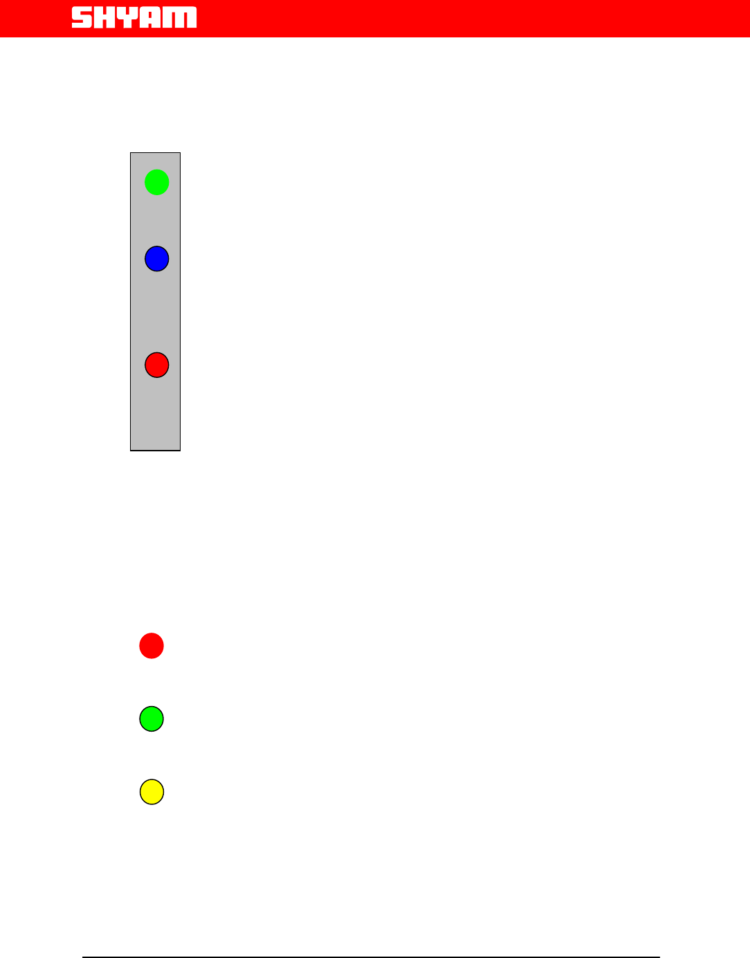
6.1 Display Details of HB-20
• UL ALIGN LED will glow after DL ALIGN is completed.
• DL ALIGN LED will blink when the system is in the Downlink
alignment mode.When the alignment is over the DL ALIGN
LED will glow.
• SHUT DOWN LED will glow when the downlink power is
more than the desired level. The systems will shutdown the
PA and then restart after 30 seconds.
Downlink RSSI is monitored continuously and display
through 3 LED’s.
• When the RSSI is greater than –40, glow the RSL High LED.
• When the RSSI in between –60 & -40, glow the RSL Mid LED.
• When the RSSI is less than –60, glow the RSL Low LED.
U/L ALIGN
D/L ALIGN
SHUT DOWN
RSL HIGH
RSL MID
RSL LOW
File Doc. No. Date Version Page
HB-20 5700 9004 054 Nov,06 2.0 16
Next Generation
Signal Enhancement
SECTION 7
Annexure 1
Technical Specification: Boosters HB-20
Parameter SMR - 800 MHz
Frequency Range Uplink : 806 - 824 MHz
Downlink : 851 - 869 MHz
Frequency Bandwidth 18 MHz
Operator, State Selective
Version OSS
*Specific models for different operators world-
wide
Contact SHYAM with coverage area &
Operator name
Nominal Gain 65 dB min
Automatic Gain adjustment 31 dB steps of 1 dB
Auto Power Control range 10 dBm
DL Power Output 10 dBm Composite
UL Power Output 10 dBm Composite
Inter Modulation Products
(two tone method, +7 dBm per
tone)
Spurious Emission (ETS 300
609 4/GSM 11.26) and (ETS
300 577 GSM 05.05)
<-36dBm @ 9 KHz – 1 GHz
<-36dBm @ 1 GHz – 12 GHz (900Mhz)
<-30dBm @ 9 KHz – 1 GHz
<-30dBm @ 1 GHz – 12 GHz (1800Mhz)/UMTS
<-36dBm @ 9 KHz – 1 GHz
<-36dBm @ 1 GHz – 12 GHz (900Mhz)
<-30dBm @ 9 KHz – 1 GHz
<-30dBm @ 1 GHz – 12 GHz (1800Mhz)/UMTS
Noise Figure 8dB Max.
V.S.W.R 1.5 Max.
Power adapter (9V DC, 2 Amp.) AC100-240V, 50/60 Hz
File Doc. No. Date Version Page
HB-20 5700 9004 054 Nov,06 2.0 17
Next Generation
Signal Enhancement
RF Connector
(Donor and Server Antenna) SMA (F) TYPE
Dimensions (HxWxD) approx. 7x3.5x2 inches
Weight Approx. 2 Lbs
Operating Temperature Range 23o F ~ 131o F

File Doc. No. Date Version Page
HB-20 5700 9004 054 Nov,06 2.0 18
Next Generation
Signal Enhancement
Annexure 2
Trouble shooting procedure HB-20
Conditions Possible Reasons & Solutions
A. Initially all the
LED’s will blink two
times
1 Check the power cord and the AC power socket
2 Please note that the AC main power has to be
within the range 100~240VAC
3 Verify the D.C Adapter output voltage is 9V.
B. Signals are not
amplified after
completing the
installation
2. Check all the connectors of the booster system for
proper connections. The “BTS” connector has to
be connected to donor antenna, and the “MS”
connector has to be connected to server antenna.
3. The poor isolation between donor and server
antenna will cause system oscillation and it may
damage the amplifier of the booster. It is to note
that the booster gain should be at least 10 db
lower than the antenna isolation.
C. The system
performed well in
the beginning but
after few days the
performance has
degraded.
1. The received signal level from the base station
might have degraded due to environmental
changes such as new building construction and so
on. If so, please follow the suggestions below:
a. Try to re-align the donor antenna towards
the base station
b. Adjust the gain attenuation of the Up or
Down link direction
c. Relocate the donor antenna to solve the
problem
2. RF Cable problem: Check the RF cable for
physical damage by rats etc. Also check for sharp
bands or RF cable pressed. Under these
File Doc. No. Date Version Page
HB-20 5700 9004 054 Nov,06 2.0 19
Next Generation
Signal Enhancement
conditions, RF signal losses could have
increased. If so, replace RF cable.
3. Indoor structural change: The signal level will
vary according to the interiors. Look for any
interior changes subsequent to the booster
installation or site survey. If so, adjust the gain of
booster or re-align the server antenna without
affecting the existing coverage.
D. Alarm indication
LED will glow in
red colour.
It indicates that the received signal level from BTS is
high or forward / reverse gain of booster is high. If
alarm persists for a long time contact SHYAM
technical support team.
File Doc. No. Date Version Page
HB-20 5700 9004 054 Nov,06 2.0 20
Next Generation
Signal Enhancement
Typical Product Application
Farm House
File Doc. No. Date Version Page
HB-20 5700 9004 054 Nov,06 2.0 21
Next Generation
Signal Enhancement
Typical Product Application
In Basement
File Doc. No. Date Version Page
HB-20 5700 9004 054 Nov,06 2.0 22
Next Generation
Signal Enhancement
For Customer Use Only ……..
For Technical Queries Contact :-
a) ds.nagi@shyamtelecom.com
b) sachin.sejwal@shyamtelecom.com
For Commercial Queries Contact:-
a) bs.yadav@shyamtelecom.com
Technical Support
For further information on the product, not prescribed in this publication, please
contact our helpdesk:
SHYAM Telecom Inc.
6,Kilmer Road, Suite D, Edison ,New Jersey 08817 ,USA
Office :- +1 732 9851324 Fax :- +1 732 907 1023
Email:repeater@shyamtelecom.com
An on line service using our Internet site is available.
Web: http//www.shyamtelecom.com
e-mail: export@shyamtelecom.com