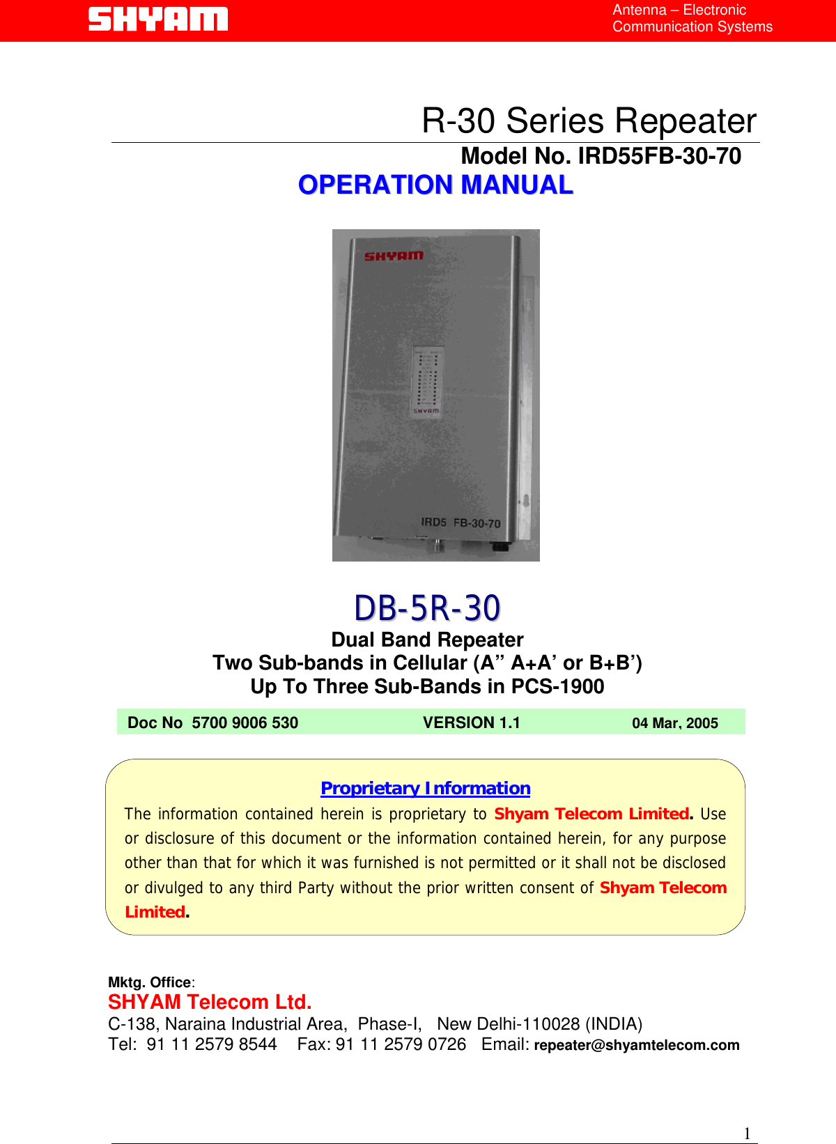
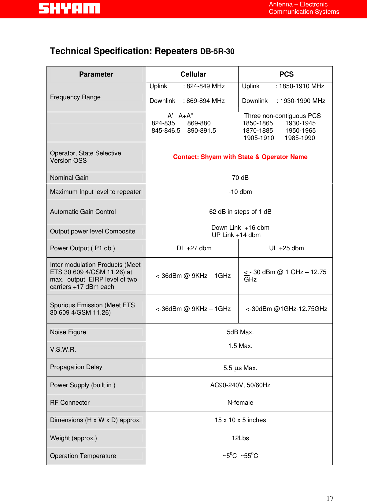
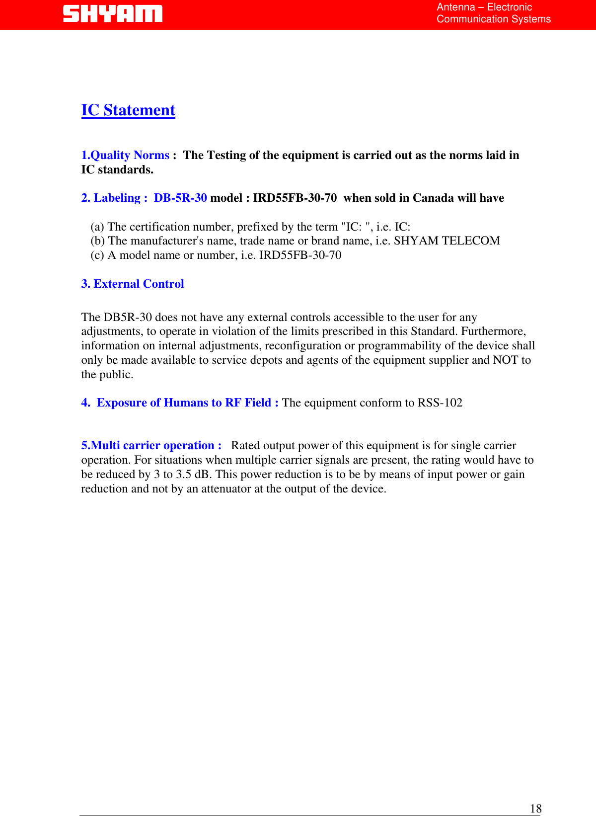
Shyam Telecom IRD55FB-30-70 Dual Band Repeater User Manual User s manual for

Shyam Telecom Inc. Dual Band Repeater User s manual for

User Manual

 Antenna – Electronic Communication Systems  R-30 Series Repeater                                            Model No. IRD55FB-30-70 OOPPEERRAATTIIOONN  MMAANNUUAALL          DDBB--55RR--3300 Dual Band Repeater Two Sub-bands in Cellular (A” A+A’ or B+B’) Up To Three Sub-Bands in PCS-1900 Doc No  5700 9006 530                            VERSION 1.1                         04 Mar, 2005       Proprietary Information The information contained herein is proprietary to Shyam Telecom Limited. Useor disclosure of this document or the information contained herein, for any purposeother than that for which it was furnished is not permitted or it shall not be disclosedor divulged to any third Party without the prior written consent of Shyam TelecomLimited. Mktg. Office: SHYAM Telecom Ltd. C-138, Naraina Industrial Area,  Phase-I,   New Delhi-110028 (INDIA) Tel:  91 11 2579 8544    Fax: 91 11 2579 0726   Email: repeater@shyamtelecom.com 1
 Antenna – Electronic Communication Systems    Contents  PREAMBLE.......................................................................................3 1.0 About the manual........................................................................3 2.0 Important Safety Information.......................................................3 3.0 Introduction: Repeater Theory / Background ..............................4 4.0 Description of DB-5R-30   Repeater Kit ......................................5 4.1 System Block Diagram...................................................................6 4.2 Contents of delivery: ...................................................................7 4.2.1 DONOR ANTENNA..................................................................7 Figure 4.2.1 :  Donor Antenna..............................................................7 4.2.2 CONVERTER MODULE ..........................................................7 Figure 4.2.2 :    Converter Module........................................................7 4.2.3 Controller module (Supervisory) ..............................................8 Figure 4.2.3 :   Monitoring and controller module.................................8 5.0 Typical In-Building Coverage ......................................................9 6.0 Installing the DB-5R-30...............................................................9 6.1 Pre-installation Considerations ...................................................9 6.2 Installation Tools .......................................................................10 6.4 Display Details of DB-5R-30 .....................................................12 6.5 In-Building Coverage Problems ................................................13 6.6 Antenna Isolation ......................................................................14 6.7   Additional Parts you will need (Optional)....................................15 Coaxial Cable Recommendations ..............................................15 Trouble shooting procedure ...............................................................16 Technical Specification: Repeaters DB-5R-30 ...................................17    2
 Antenna – Electronic Communication Systems   PREAMBLE  In cellular systems repeaters are used, to enhance the coverage of a base station in a region where, due to topological conditions, poor field strengths disable communication. SHYAM is a leading manufacturer of repeaters. These repeaters provide excellent electrical characteristics, are lightweight and easy to install.   Any intervention has to be performed by authorized persons only. If you need technical assistance, please contact at the following address:  SHYAM Telecom Ltd.  C-138, Naraina Industrial Area,  Phase-I,   New Delhi-110028 (INDIA) Tel:  91 11 2579 8544    Fax: 91 11 2579 0726   Email: repeater@shyamtelecom.com  Under consideration of all references given in this manual, the repeater should be taken into service without any complications and should operate trouble free for a long time. However we have country wide after sales support network to assist you if required. Please visit to our web site www.shyamtelecom.com for our country wide after sales support offices.  1.0  About the manual   The “Operation manual” is intended to be used for SHYAM DB-5R-30 repeater installation.  It contains the general guidelines for the field engineers /technicians. Read carefully before starting the DB-5R-30 repeater installation.  2.0  Important Safety Information  The DB-5R-30   repeater has been designed for maximum safety when installed and operated according to the instructions in this manual. Refer to all safety instructions as per the antenna installation instruction sheets.  Do not bypass any of the safety features with the equipment provided, nor operate the system in an inappropriate environment.  3 WARNING! Installation of antennas near power lines is dangerous. For your safety, follow all installation directions and keep safe distance from any high voltage power lines that could result in shock or loss of life.
  4Antenna – Electronic Communication Systems  WARNING! This equipment complies with FCC & IC radiation exposure limits set forth for an uncontrolled environment. This transmitter must not be co-located or operating in conjunction with any other antenna or transmitter. For mobile or fixed location transmitters, the minimum separation distance is greater than 40 cm, even if calculations indicate that the MPE distance would be less.  Additional wiring required to install the DB-5R-30   system should comply with national or local governing Electrical Codes. Indoor RF coaxial cable installations should comply with local Electrical Code requirements. The DB-5R-30   repeater should only be installed in restricted access areas such as dedicated equipment rooms or closets.  The DB-5R-30   repeater is designed for indoor application; the housing is not waterproof. So please keep it away from water, rain and any chemical liquid. Do discharge the static before you touch the connectors of the repeater. Do not open the module inside the repeater unless you are authorized. The power supply unit in the DB-5R-30   repeater is supplied from the mains (primary AC power) that contains dangerous voltage level which will cause electric shock, Please turn off the mains before you install / uninstall the repeater. The primary AC power should be in the range of AC90-240V, 50/60Hz. Repeater will be damaged if the primary AC power is out of the range.  The RF electric performance of the DB-5R-30   Cellular / PCS repeaterconforms to ETSI requirement of the inter modulation and spuriousemission. It avoids the interference problem. 3.0  Introduction: Repeater Theory / Background  In mobile cellular communication system, repeaters provide the radio frequency (RF) coverage to areas, which either lack signal, or the required signal strength for adequate mobile phone performance. To the typical user, this translates to the inability to place or receive mobile phone calls in or out of the area, and in most cases will result in a dropped call while entering into the poor coverage area. Insufficient wireless coverage can occur both indoors and outdoors, and may include indoor areas such as office buildings, parking garages, apartment buildings, shopping malls, and residential homes. Out door areas are degraded by geographic topologies such as mountains, valleys, dense foliage and high rising urban landscapes which can easily degrade or obstruct the cell site’s signal from
 Antenna – Electronic Communication Systems the mobile phone.  The weak coverage problem can be solved by installing an active repeater system, designed for use in a multitude of installation configurations. Repeater systems provide an effective solution by redirecting, filtering and amplifying the available signal at the donor antenna, into the weak coverage area, through a properly selected interior coverage antenna. The illumination of the weak coverage area allows the user’s handset to operate as intended within the building or weak coverage area, while maintaining the user’s call clarity and quality, which reduces service complaints and potential subscriber churn.   Figure 1:  Typical Repeater/Coverage Configuration  4.0  Description of DB-5R-30   Repeater  The DB-5R-30   repeater system contains a high power, automatic power control, bi-directional amplifier (BDA) used along with a donor antenna (Optional outdoor yagi antenna) and server antenna ( Optional indoor omni directional antenna), specifically designed for interior configurations. The donor antenna must be pointed toward the cell of the base station from where the signal is to be picked up and is usually mounted on the exterior of the building so as to receive the maximum forward signal level from the base station. The indoor antenna is specifically designed to blend into the ceiling of a typical office providing RF signal in all directions downward and outward from the installation point. For in-building configurations requiring higher gain or directional RF signal, such as a long hallway or corridor, a medium gain directional antenna may cover the area best by mounting the antenna to the opposing wall, where coverage is required.  5
 Antenna – Electronic Communication Systems   4.1 Typical application                      DB5R30 Repeater                 6
 Antenna – Electronic Communication Systems    4.2  Contents of delivery:   ITEMS QUANTITY Repeater DB-5R-30  1 PC interface cable (RS 232)   1 Power cable 3 pin – 3 meter long   1 Operation & Installation manual  1 CD containing the application software  1  4.2.1 DONOR ANTENNA (Optional )  Donor antenna is used to receive signal from the base station and switch electromagnetic wave into RF signal and vice versa. The antenna with more than 10-14dB gain sends received signal to the repeater and transmits uplink signals amplified by the repeater.             Figure 4.2.1 :  Donor Antenna  4.2.2 CONVERTER MODULE  The basic block of converter module composed of L.O. frequency mixer, filter and intermediate amplifier. When the low noise amplified signal gets into the conversion module, it mixes frequency with the local oscillation signal to generate IF in which it passes through channel selective filters and achieve frequency selection. The L.O. frequency can be changed for the selection of different channels.   7          output connector  Input connector  Motherboardconnector  Figure 4.2.2 :    Converter Module
 Antenna – Electronic Communication Systems     4.2.3 Controller module (Supervisory)  The controller module is a micro controller. The man-machine communication between the cellular operator and the repeater can be done via the control module by using any one of the following methods:   •  RS 232 interface   •  GSM / CDMA modem  (Optional)  By using the GSM modem, the repeater can be controlled remotely. (For centralized RMS of repeaters system)  Frequency and gain of channels, power down of RF stages and ALC can be controlled and status messages can be received remotely. In case the GSM modem is connected, automatic alarm messages can be received at remote locations. Programming connector Motherboard connector  Display panel connector  Figure 4.2.3 :   Monitoring and controller module   All the DB5R-30 configuration parameters are stored:  i.  Serial Number of the repeater ii.  Repeater Site Address  iii. Channel number iv.  Frequency details, Uplink and Downlink v.  Attenuation for repeater gain setting  vi.  Output power limit vii.  Power amplifier (PA) ON/OFF function    viii.  Power amplifier (PA) ON/OFF function     8
 Antenna – Electronic Communication Systems     5.0  Typical In-Building Coverage   The DB-5R-30   is designed to provide optimal coverage for areas of 1000 Sq Meters (10,000 sq. ft) to 2,000 Sq Meters (20,000 sq. ft). However, performance also depends on the amount of in-building shadowing and the available forward signal level at the donor antenna. Typical coverage is usually planned for relatively small areas such as large conference rooms or several adjacent rooms in smaller office areas. Please refer figure 2 and figure 3 for example. Coverage is primarily determined by the available forward signal level at the outdoor yagi antenna input, loss due to the RF cable length, type of RF cable installed and achievable isolation  for optimum DB-5R-30   performance. Indoor coverage varies greatly due to the nature of various building construction techniques and materials. Refer to SHYAM Link budget calculator (Table 1 below) for repeaters; approximations of signal level/coverage can be determined with the following assumptions:  i.  12 dBi   donor antenna., 0 dBi or 7dBi indoor directional antenna. ii.  Installed total cable and connector loss of approximately 5 dB (40 Meters (125feet) of typical 1/4” coaxial foam cable). iii.  Interior building structure consists of typical vertical stud and drywall composition. iv.  Isolation of 80 dB or greater between donor and server antennas   6.0 Installing the DB-5R-30  6.1 Pre-installation Considerations  Once the expected coverage area is determined and a site installation plan is established (as per the site survey format), a pre-installation checklist should be considered and reviewed for the following items:  1.  Identify the service provider’s base station location and verify that the available signal strength at the exterior of the installation location is adequate. 2.  Identify the installation location for the donor antenna, and review the antenna manufacturer’s installation procedures for additional considerations. 9
 Antenna – Electronic Communication Systems Ensure that the donor antenna has a direct line-of-site to the service provider’s base station. If the line-of-site is obstructed, determine the azimuth position by using a magnetic compass for approximate alignment of donor antenna with base station antenna.  DB-5R-30 installation site location criterion  i.  A cool, dry location, away from other heat generating appliances or equipment. ii.  Accessibility to available electric power point. iii.  Flat, structural mounting surface. iv.  Providing a short, low loss RF cable connection to the indoor antenna. v.  Maintaining RF isolation of 80 dB or more between antennas (Refer Troubleshooting/ RF Isolation). vi.  Accommodation for the indoor antenna providing line-of-site coverage to as much of the coverage area as possible. 6.2 Installation Tools  You will need the following basic tools for installation: i. Standard wrenches/screwdrivers/cable stripper/cable cutter/pliers set for installing the DB-5R-30   Unit and antennas. (Refer to the manufacturer’s recommendations for installing the antennas).  ii.  RF coaxial cable connection tools for installing connectors. iii.  Soldering iron and solder. iv. Multi-meter. v.  Mobile handset loaded (e.g. Nokia) with Net engineering software to be used for signal level measurement.   vi.  Magnetic compass for measuring the azimuth of the BTS and repeater site.   6.3 Installation Procedure   1.        RF coaxial cable installation must comply with local or National Electrical    Codes and must be a nominal 50 ohm impedance type cable. Pull and route   the RF coaxial cables as per the site installation plan. 10
 Antenna – Electronic Communication Systems  2.        Fix the supplied connectors to the RF coaxial cable and verify the following:  •  The center conductor to outer shield of RF coaxial cable indicates a “Open Circuit” condition. •  Check for any short circuit between center conductor and outer shield. •  Short one end of the conductor between center conductor and outer shield by piece of wire temporarily and check the other end of conductor for any break in the RF cable.   3.   Record the DB-5R-30   serial number for use when contacting SHYAM customer service for support. 4   Mount the DB-5R-30   unit on the intended wall surface using the appropriate screws. 5  Install the indoor coverage antenna according to the antenna manufacturer’s instructions. Connect the RF coaxial cable between the indoor antenna and the “MS” port on the DB-5R-30   unit. 6  Install the donor antenna (Outdoor Yagi antenna) according to the antenna manufacturer’s instructions. Connect the RF coaxial cable between the donor antenna and the “BTS ” port on the DB-5R-30   unit.   Please remember the following tips:  i.  Ensure that antenna connectors and antenna cable connectors are clean and dry. ii.  The RF cables must not be kinked, cut or damaged in any way. iii.  Connect the RF cables to the antennas taking care to avoid cross threading or stripping. The RF connections should be snug and tight. iv.  Seal the antenna and repeater connectors with waterproof sealant or the appropriate weather tight boot.       11
 Antenna – Electronic Communication Systems     6.4  Display Details of DB-5R-30              •  UL ADJ. will blink when system is in Uplink Alignment mode.  •  DL ADJ. will blink when system is in Downlink Alignment mode.  •  ALC alarm will blink when, when system is in ALC   •  Status RED LED will Glow when the system goes out of order (poor isolation). The system needs a restart after the sufficient isolation is provided  •  DL RSL alarm will glow when some RSL alarm in DL   •  Alarm indicator glow when some alarm is present in system.      12
 Antenna – Electronic Communication Systems     •  Downlink RSSI is continuously monitored and displayed through 8 LED’s. DL RSSI (In dBm)  Y  G1 G2 G3 G4 G5 G6  R RSSI< -85  H  L L L L L L L -85<=RSSI<-80  H  H  L L L L L L -80<=RSSI<-75  H  H H L L L L L -75<=RSSI<-70  H  H H H L L L L -70<=RSSI<-65  H  H H H H L L L -65<=RSSI<-60  H  H H H H H L L -60<=RSSI<-55  H  H H H H H H L RSSI>=-55  H  H H H H H H H  6.5  In-Building Coverage Problems  If the coverage area appears to be smaller than the installation site plan, there are only a few possibilities that limit the signal level in the area.  i.  Physical obstructions degrading the signal level  – Visually inspect the area of weak coverage. If possible, rearrange objects that may interfere with the signal path. Pay particular attention to large metallic objects that may reflect or block the signal to the weak coverage area. If weak coverage area still persists, check the following: a.  Inspect the indoor RF coaxial cable and its connection with connector b.  Indoor antenna direction and its tilting c.  DB-5R-30   repeater gain setting    ii.  Defective indoor coaxial cable or antenna – Check the RF coaxial cable and antenna. If necessary, replace each individually with a known functional unit, and verify the respective signal level. This can be achieved by  iii.  observing the signal strength indicator on a mobile handset that has an unobstructed line-of-site view, 15 – 20 feet (4 – 5 m) from the indoor antenna. If the signal level increases at this test location, re-verify the signal 13
 Antenna – Electronic Communication Systems level in the weak coverage area. If the signal level remains marginal, inspect the DB-5R-30   unit.  iv. DB-5R-30   Defective – Replace the DB-5R-30   unit with a known operational unit. Verify the signal level at the unobstructed test location. If the signal level increases, re-verify the weak coverage area. If the weak coverage area remains marginal, an additional indoor antenna or DB-5R-30   may be required to cover the additional area. If the original DB-5R-30   is defective, contact Technical customer support team at 91-11-25798544 or email at repeater@shyamtelecom.com. The DB-5R-30   serial number must be available to establish a return authorization.  6.6 Antenna Isolation  Antenna isolation is defined by the path loss or attenuation, between the donor and server antennas. It is important to ensure that the antennas are sufficiently separated, such that the signal transmitted by donor antenna is not received by server antenna and vice versa. For optimal performance, the separation of the two antennas must provide a path loss of at least 10 dB greater than the gain of the DB-5R-30   repeater.  In most cases, isolation will be achieved by properly locating the donor and server antennas, respectively. The optimal location for the donor antenna is high above the roofline, and exterior to the building. The indoor coverage antenna (server) should be installed inside, near or below the ceiling. Following these guidelines should ensure adequate isolation between antennas.  i.  Never mount the donor or server antenna near a window, where signal can easily pass through the glass. ii.  Mount the donor antenna as high as physically possible to the exterior of the building, maximizing the vertical separation between the donor and server antennas. The donor antenna should point towards the base station site. iii.  Install the antennas taking advantage of any existing building structure such as brick walls, metal roofs, or multiple wall structures to additionally attenuate the path between them.  iv.  Whenever using directional antennas inside the building to cover corridors 14
 Antenna – Electronic Communication Systems and hallways, point the indoor antenna away from the donor antenna location.    v.  In extreme cases, the building configuration may not allow for such separation and isolation. If additional isolation is required, coaxial attenuator may be inserted between the donor antenna and the DB-5R-30 repeater or reduce the forward path signal using the attenuation DIP switch with the likely compromise to the overall coverage within the building.   6.7   Additional Parts you will need (Optional)  i.  RF coaxial cable length and type as per the actual site requirement ii.  Server antennas: In-Building Coverage Antenna  a.  2dbi Omni directional-Ceiling Mount:    Type No. SIOA 800 / 1900 b.  6dbi Directional Antenna:               Type No. SIDA 800 / 1900   c.  7dbi Directional Antenna:              Type No. SIDA 800 / 1900 iii.  Type N male plug connectors – 4 no. iv.  Required to couple the coaxial cable to the antennas – 2 no. v.  Required to couple the coaxial cable to the DB-5R-30   – 2 no. vi.  Power divider (SPD –n): as per the actual site requirement (n= 2,3,4 & 8) vii. Coaxial attenuator   Coaxial Cable Recommendations  The DB-5R-30   does not include the RF coaxial cables or connectors required for installation. When selecting the appropriate cable for the installation, consider the total loss of the cable due to length and type. Keeping cable loss to a minimum will maintain optimal performance of the DB-5R-30.   15
 Antenna – Electronic Communication Systems   Trouble shooting procedure    Conditions  Possible Reasons & Solutions A.  Power lamp does not    glow after turning on the power switch. 1    Check the power cord and the AC power socket 2   Please note that the AC main power has to be within the range 90~240VAC B.  Signals are not amplified after completing the installation 1.  Check the AC power cord and make sure the power switch is on. 2.  Check all the connectors of the repeater system for proper connections. The “BTS” connector has to be connected to donor antenna, and the “MS” connector has to be connected to server antenna. 3.  The poor isolation between donor and server antenna will cause system oscillation and it may damage the amplifier of the repeater.  It is to note that the repeater gain should be at least 10 db lower than the antenna isolation.      C.  The system performed well in the beginning but after few days the performance has degraded. 1.  The received signal level from the base station might have degraded due to environmental changes such as new building construction and so on. If so, please follow the suggestions below: a.   Try to re-align the donor antenna towards the base station b.   Adjust the gain attenuation of the Up or Down link direction c.   Relocate the donor antenna to solve the problem  2.  RF Cable problem:  Check the RF cable for physical damage by rats etc. Also check for sharp bands or RF cable pressed. Under these conditions, RF signal losses could have increased. If so, replace RF cable. 3.  Indoor structural change: The signal level will vary according to the interiors. Look for any interior changes subsequent to the repeater installation or site survey. If so, adjust the gain of repeater or re-align the server antenna without affecting the existing coverage.   16
 Antenna – Electronic Communication Systems   Technical Specification: Repeaters DB-5R-30   Parameter Cellular PCS Frequency Range Uplink         : 824-849 MHz  Downlink   : 869-894 MHz Uplink         : 1850-1910 MHz Downlink     : 1930-1990 MHz    Sub Band Selection           A’   A+A”                             Three non-contiguous PCS  824-835       869-880                  1850-1865       1930-1945    845-846.5    890-891.5               1870-1885       1950-1965                                                        1905-1910      1985-1990          Operator, State Selective Version OSS  Contact: Shyam with State & Operator Name Nominal Gain  70 dB    Maximum Input level to repeater  -10 dbm Automatic Gain Control  62 dB in steps of 1 dB Output power level Composite  Down Link  +16 dbm                                   UP Link +14 dbm  Power Output ( P1 db )   DL +27 dbm   UL +25 dbm Inter modulation Products (Meet ETS 30 609 4/GSM 11.26) at max.  output  EIRP level of two carriers +17 dBm each <-36dBm @ 9KHz – 1GHz  < - 30 dBm @ 1 GHz – 12.75 GHz Spurious Emission (Meet ETS 30 609 4/GSM 11.26)  <-36dBm @ 9KHz – 1GHz  <-30dBm @1GHz-12.75GHz Noise Figure  5dB Max. V.S.W.R.  1.5 Max.  Propagation Delay  5.5 µs Max. Power Supply (built in )  AC90-240V, 50/60Hz RF Connector  N-female Dimensions (H x W x D) approx.  15 x 10 x 5 inches Weight (approx.)  12Lbs Operation Temperature  ~50C  ~550C    17
 Antenna – Electronic Communication Systems     IC Statement   1.Quality Norms :  The Testing of the equipment is carried out as the norms laid in       IC standards.  2. Labeling :  DB-5R-30 model : IRD55FB-30-70  when sold in Canada will have            (a) The certification number, prefixed by the term "IC: ", i.e. IC:     (b) The manufacturer's name, trade name or brand name, i.e. SHYAM TELECOM    (c) A model name or number, i.e. IRD55FB-30-70  3. External Control  The DB5R-30 does not have any external controls accessible to the user for any adjustments, to operate in violation of the limits prescribed in this Standard. Furthermore, information on internal adjustments, reconfiguration or programmability of the device shall only be made available to service depots and agents of the equipment supplier and NOT to the public.  4.  Exposure of Humans to RF Field : The equipment conform to RSS-102   5.Multi carrier operation :   Rated output power of this equipment is for single carrier operation. For situations when multiple carrier signals are present, the rating would have to be reduced by 3 to 3.5 dB. This power reduction is to be by means of input power or gain reduction and not by an attenuator at the output of the device.                     18
 Antenna – Electronic Communication Systems        For Customer Use Only ……..                                       19 SHYAM Telecom Ltd. A-60, Naraina Industrial Area,  Phase-I,   New Delhi-110028 (INDIA) Tel:  +91-11-51411076    Fax: +91-11-51411078   Email: repeater@shyamtelecom.com
 Antenna – Electronic Communication Systems   20

Navigation menu