Sichuan Changhong Electronic Component WIFI-2 WIFI module User Manual WIFI 2 Module x
Sichuan Changhong Electronic Component Co., Ltd. WIFI module WIFI 2 Module x
Users Manual

WIFI-2
WIFI Module
四川长虹电子部品有限公司 Sichuan ChanghongElectronic Component Co.,Ltd.page1 of 8
WIFI Module
WIFI-2
User Manual / User Guide
WIFI-2
WiFi Module
四川长虹电子部品有限公司 Sichuan ChanghongElectronic Componen Co.,Ltd.page2 of 8
1. Overview
WIFI-2 Module has developed by Sichuan Changhong
Electronic Component Co., Ltd.
This document is to specify the product requirements
for 802.11 b/g/n Module.This Card is based on
Realtekchip that cpomplied with IEEE 802.11g,
IEEE 802.11b, IEEE 802.11n standard
from 2.4G-2.5GHz,and it can be used to provide up
to 54Mbps for 802.11g,11Mbps for 802.11b and
150Mbps for 802.11n to connect your wireless LAN.
WIFI-2 ModuleSupport infrastructure networks via
Access Point and ad-hoc network via peer-to-peer
communication.the driver supports the following
operating systems: Windows 2000,XP,Vista.that
cpomplied withRoHS.
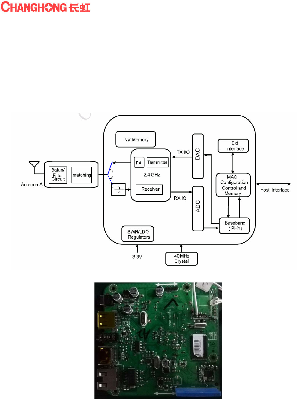
2. ChipDescription
The Realtekchip is a highly integrated single-chip 802.11n Wireless LAN (WLAN) network interfacecontroller. It
combines a WLAN MAC, acapable WLANbaseband, and WLAN RF in a single chip. The chip provides a complete
solution for a highthroughput performance integrated wireless LAN device.
The chip WLAN baseband implements Orthogonal Frequency Division Multiplexing (OFDM)with transmit andreceive
path and is compatible with the IEEE 802.11n specification. Features includeone spatial stream transmission, short
guard interval (GI) of 400ns, spatial spreading, and transmission over20MHz and 40MHz bandwidth.
For legacy compatibility, Direct Sequence Spread Spectrum (DSSS), Complementary Code Keying (CCK)and OFDM
baseband processing are included to support all IEEE 802.11b and 802.11g data rates.Differential phase shift keying

WIFI-2
WiFi Module
四川长虹电子部品有限公司 Sichuan ChanghongElectronic Componen Co.,Ltd.page3 of 8
modulation schemes, DBPSK and DQPSK with data scrambling capability, areavailable, and CCK provides support
for legacy data rates, with long or short preamble. The high-speedFFT/IFFT paths, combined with BPSK, QPSK,
16QAM, and 64QAM modulation of the individualsubcarriers and rate compatible punctured convolutional coding
with coding rate of 1/2, 2/3, 3/4, and 5/6,provide higher data rates of 54Mbps and 150Mbps for IEEE 802.11g and
802.11n OFDM respectively.
The chip WLAN Controller builds in an enhanced signal detector, an adaptive frequency domainequalizer, and a
soft-decision Viterbi decoder to alleviate severe multi-path effects and mutual interference inthe reception of multiple
streams.
Efficient IQ-imbalance, DC offset, phase noise, frequency offset, and timing offset compensations areprovided for the
radio frequency front-end. Selectable digital transmit and receive FIR filters are provided tomeet transmit spectrum
mask requirements and to reject adjacent channel interference, respectively.
The chip WLAN Controller supports fast receiver Automatic Gain Control (AGC) withsynchronous and asynchronous
control loops among antennas, antenna diversity functions, and adaptivetransmit power control function to obtain the
better performance in the analog portions of the transceiver.
The chip WLAN MAC supports 802.11e for multimedia applications, 802.11i for security, and802.11n for enhanced
MAC protocol efficiency. Using packet aggregation techniques such as A-MPDU withBA and A-MSDU, protocol
efficiency is significantly improved. Power saving mechanisms such as LegacyPower Save, and U-APSD, reduce the
power wasted during idle time, and compensates for the extra powerrequired to transmit OFDM. The RTL8188ETV
provides simple legacy and 20MHz/40MHz co-existencemechanisms to ensure backward and network compatibility.
3. Chip Features
General
46-pin QFN
CMOS MAC, Baseband PHY, and RF in asingle chip for IEEE 802.11b/g/n compatibleWLAN
Complete 802.11n solution for 2.4GHz band
72.2Mbps receive PHY rate and 72.2Mbpstransmit PHY rate using 20MHz bandwidth
150Mbps receive PHY rate and 150Mbpstransmit PHY rate using 40MHz bandwidth
Compatible with 802.11n specification
Backward compatible with 802.11b/gdevices while operating in 802.11n mode
StandardsSupported
IEEE 802.11b/g/n compatible WLAN
IEEE 802.11e QoS Enhancement (WMM)
802.11i (WPA, WPA2). Open, shared key,and pair-wise key authentication services
WLANMACFeatures
Frame aggregation for increased MACefficiency (A-MSDU, A-MPDU)
Low latency immediate High-ThroughputBlock Acknowledgement (HT-BA)
PHY-level spoofing to enhance legacycompatibility
Power saving mechanism
Channel management and co-existence
Transmit Opportunity (TXOP) ShortInter-Frame Space (SIFS) bursting forhigher multimedia bandwidth
WLANPHYFeatures
IEEE 802.11n OFDM
One Transmit and one Receive path (1T1R)
20MHz and 40MHz bandwidth transmission
Short Guard Interval (400ns)
WIFI-2
WiFi Module
四川长虹电子部品有限公司 Sichuan ChanghongElectronic Componen Co.,Ltd.page4 of 8
DSSS with DBPSK and DQPSK, CCKmodulation with long and short preamble
OFDM with BPSK, QPSK, 16QAM, and64QAM modulation.Convolutional Coding Rate: 1/2, 2/3, 3/4,and 5/6
Maximum data rate 54Mbps in 802.11g and150Mbps in 802.11n
Hardware antenna diversity in per packetbase
Selectable receiver FIR filters
Programmable scaling in transmitter andreceiver to trade quantization noise againstincreased probability of
clipping
Fast receiver Automatic Gain Control(AGC)
On-chip ADC and DAC
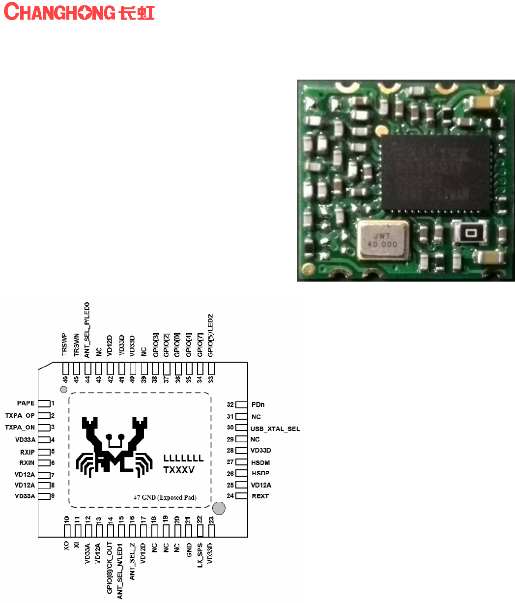
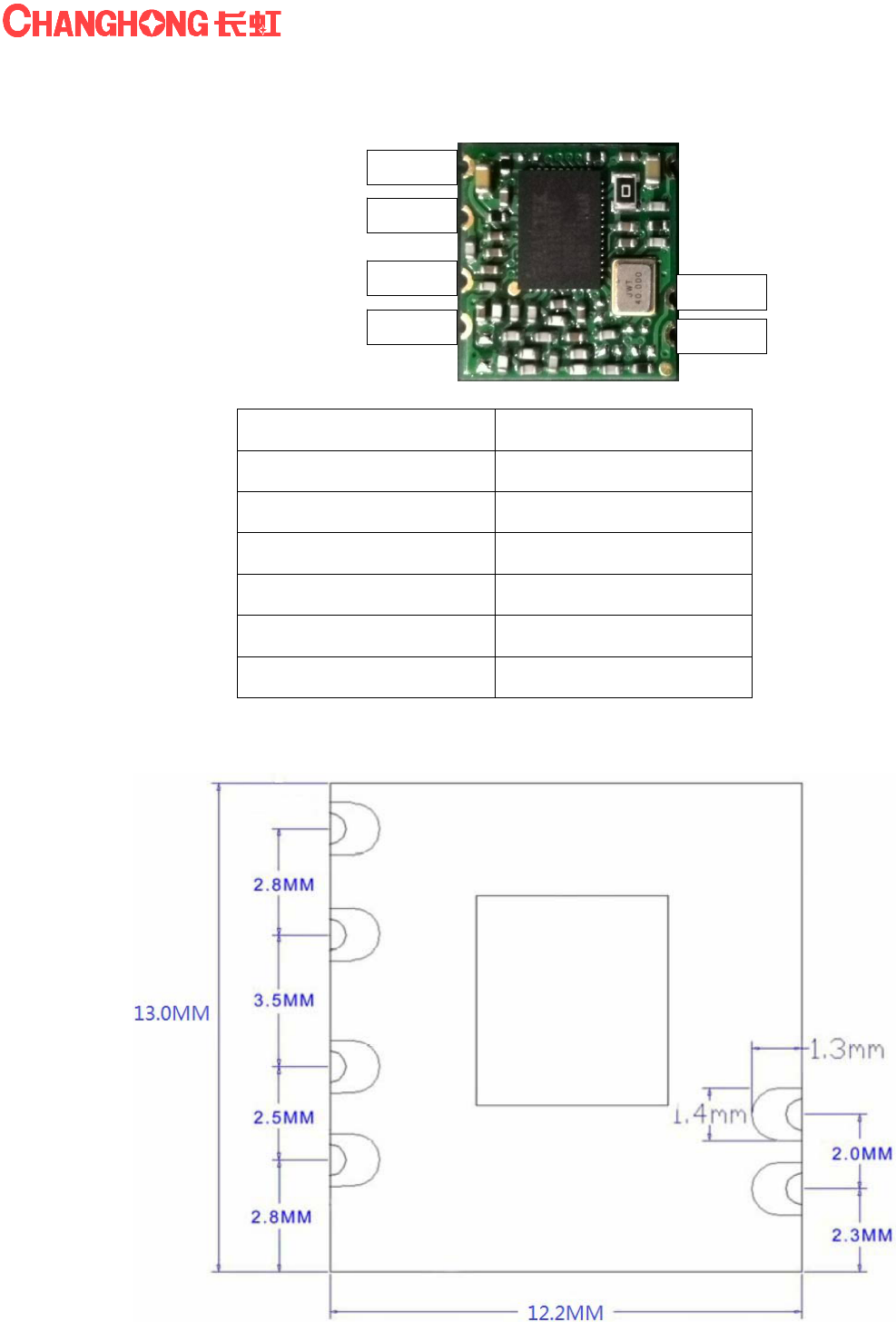
4. Module Overview
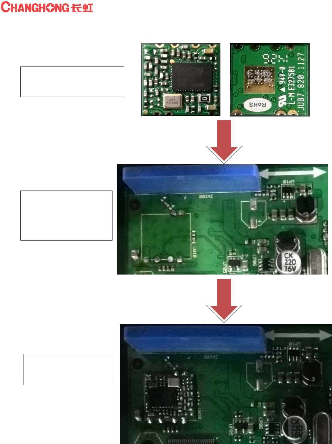
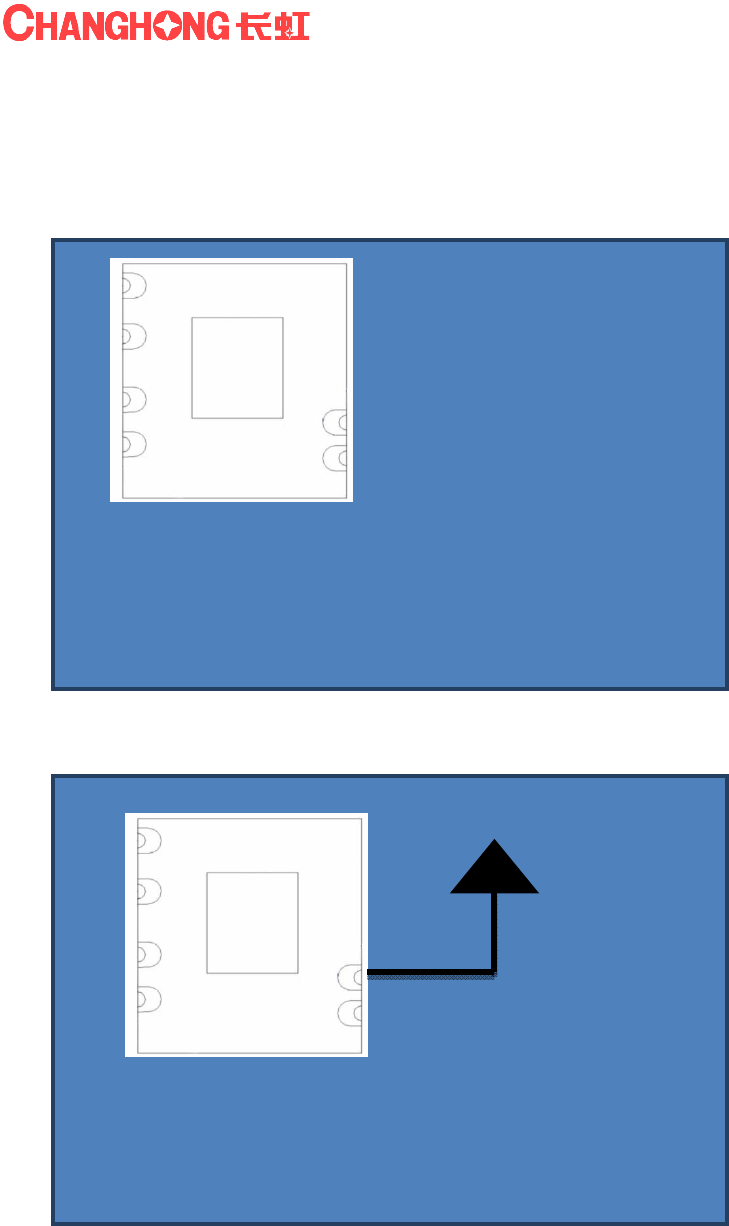
5. Installation Guide
Finished Assembly
WIFI-2
WiFi Module
四川长虹电子部品有限公司 Sichuan ChanghongElectronic Componen Co.,Ltd.page5 of 8
Master PCB (examples)
1、Check WIFI-2 Module
connection pin isclean
forsolderin
g
.
2、Ready the Master
PCB which willconnect
withWIFI-2 Module.
Check connectionpads
is clean forsoldering.
3、Place the Module
on the Master PCB with
SMT
WIFI-2
WiFi Module
四川长虹电子部品有限公司 Sichuan ChanghongElectronic Componen Co.,Ltd.page6 of 8
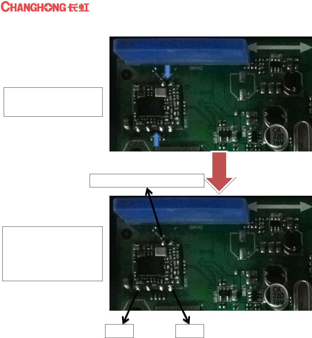
TestCheck
4、After soldering,Check all
pads arewell connected.
VCC GND
5、Connect DC Power
3.0-3.6V onVCC and GND
onMaster PCB.
The Pin connect to Antenna
byImpedance matching
network.
Im
p
edance matchin
g
networ
k
WIFI-2
WiFi Module
四川长虹电子部品有限公司 Sichuan ChanghongElectronic Componen Co.,Ltd.page7 of 8
6. Pin Name & Dimension
Pin TYPE
1 VCC
(
3.3v
)
2 UDN
3 UDP
4 GND
5 GND
6 ANT
13.0 x 12.2 x 1.0 mm
1 VCC
2UDN
3UDP
4 GND 5 GND
6ANT
WIFI-2
WiFi Module
四川长虹电子部品有限公司 Sichuan ChanghongElectronic Componen Co.,Ltd.page8 of 8
7. WIFI-2 Module Placement Tips
1) To enable DTM mode for R/F Test likeFCC test…etc.,
UDNand UDPpad require to connect to RF Equipment
UDNand UDP pad located on the back side of the module.
Reserve hole at Main PCB for soldering UDN&UDPpads for RF Equipment .
2) Module Soldering on Main PCB, ensure the input impedance of the antenna is 50Ω.
3) Connect All Module Ground Pads to main PCB Ground to obtain betterperformance.
Main Board
Main Board
FCC Statement:
The final end product must be labeled in a visible area with the following "Contains TX FCC
ID:2AC49WIFI-2". If the size of the end product is smaller than 8x10cm, then additional
FCC part 15.19 stayement is required to be availale in the users manual:
This device complies with part 15 of the FCC Rules. Operation is subject to the following
two conditions: (1) This device may not cause harmful interference, and (2) this device
must accept any interference received, including interference that may cause undesired
operation.
This equipment has been tested and found to comply with the limits for a Class B digital
device, pursuant to part 15 of the FCC Rules. These limits are designed to provide
reasonable protection against harmful interference in a residential installation. This
equipment generates, uses and can radiate radio frequency energy and, if not installed
and used in accordance with the instructions, may cause harmful interference to radio
communications. However, there is no guarantee that interference will not occur in a
particular installation. If this equipment does cause harmful interference to radio or
television reception, which can be determined by turning the equipment off and on, the
user is encouraged to try to correct the interference by one or more of the following
measures:
—Reorient or relocate the receiving antenna.
—Increase the separation between the equipment and receiver.
—Connect the equipment into an outlet on a circuit different from that to which the
receiver is connected.
—Consult the dealer or an experienced radio/TV technician for help.
Caution: Any changes or modifications not expressly approved by the party responsible
for compliance could void the user's authority to operate the equipment.
FCC Radiation Exposure Statement:
This modular complies with FCC RF radiation exposure limits set forth for an uncontrolled environment.
This transmitter must not be co-located or operating in conjunction with any other antenna or transmitter.
Due to missing shielding the module is strictly limited to integration by the Grantee himself or his dedicated
OEM integrator under control of the Grantee.However, the OEM integrator is still responsible for testing
their end-product for any additional compliance requirements required with this module installed.
This device is intended only for OEM integrators under the following conditions:
1)This module is granted as a Limited Modular Approval.
2)This device has been designed to operate with a Monopole antenna having a maximum gain of 2dBi.Only
this type of antenna may be used.
FCC RF Radiation Exposure Statement:
1.This Transmitter must not be colocated or operating in conjunction with any other antenna or transmitter.
2.This equipment complies with FCC RF radiation exposure limits set forth for an uncontrolled environment.
This equipment should be installed and operated with a minimum distance of 20 centimeters between the
radiator and your body.