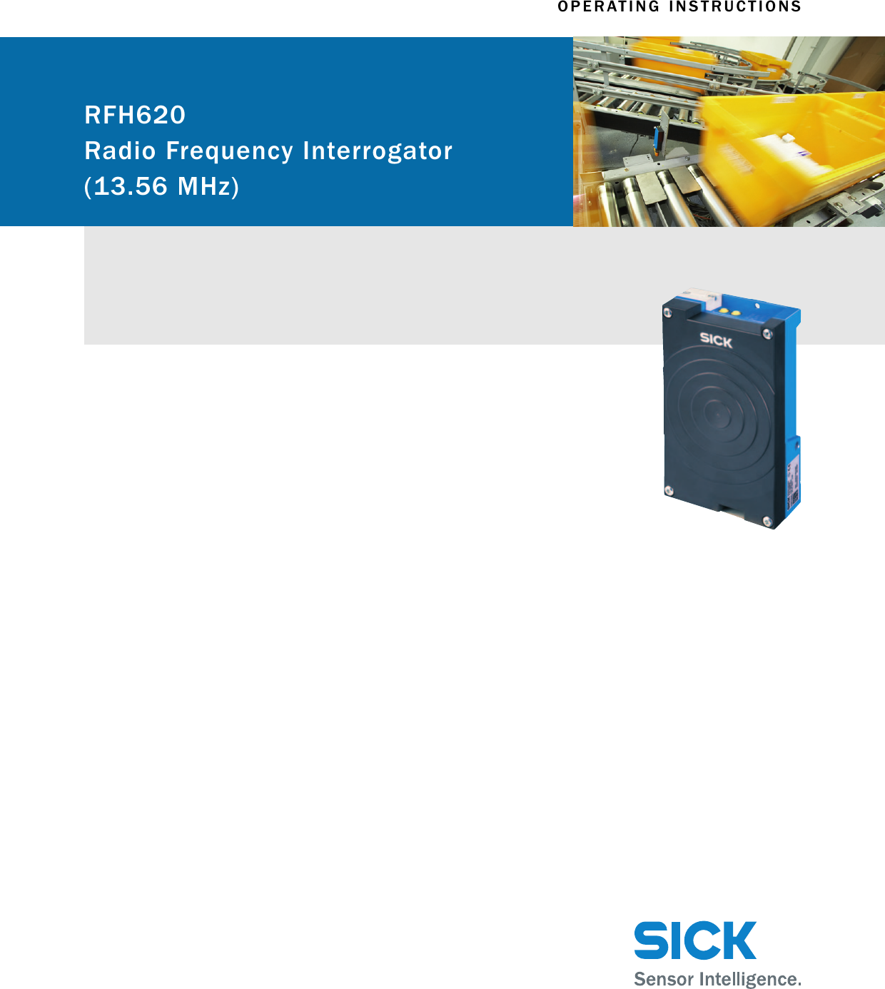
Sick RFH620 RFID User Manual
Sick AG RFID
UserManual.wiki
>
Sick
>
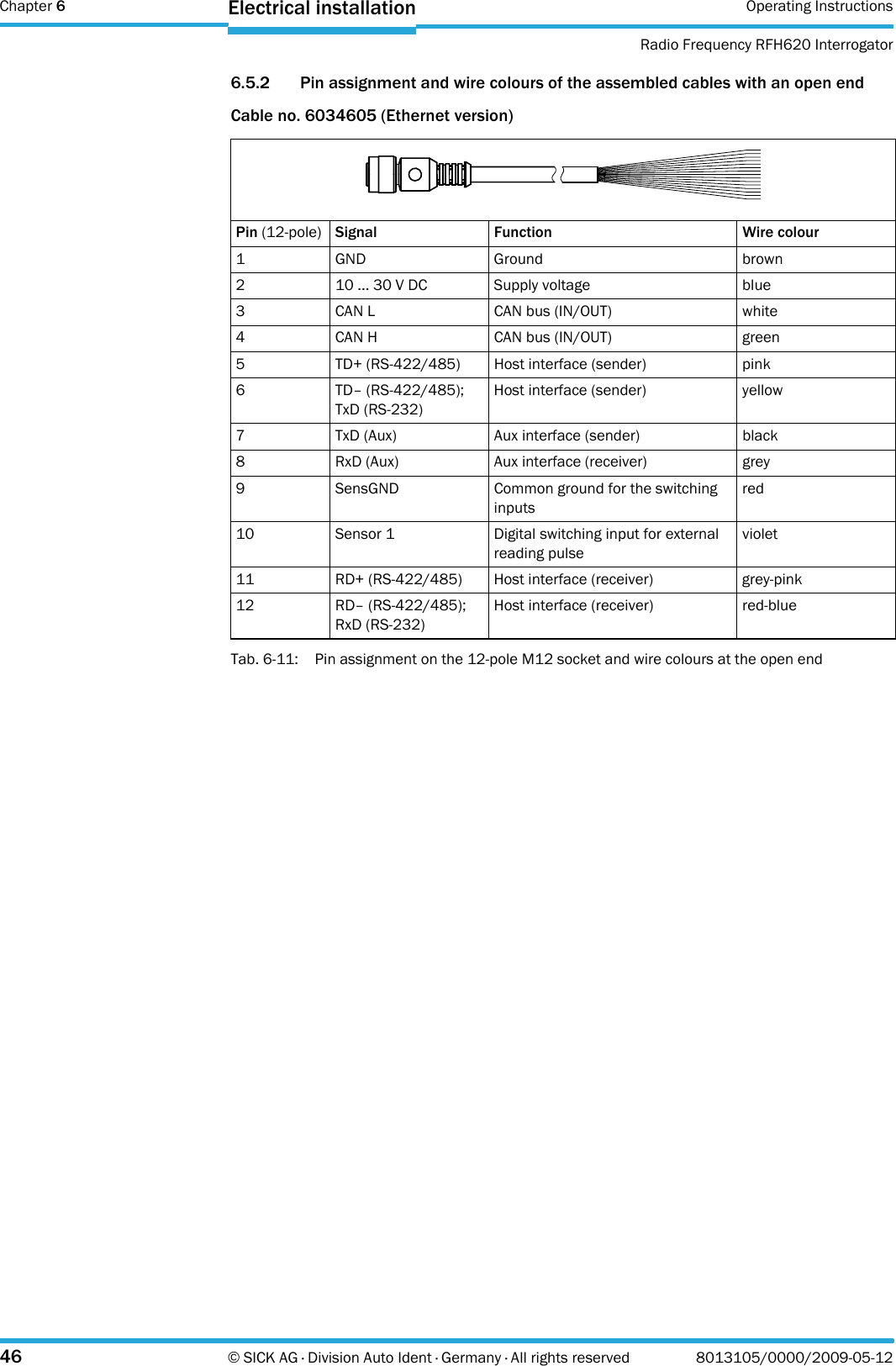
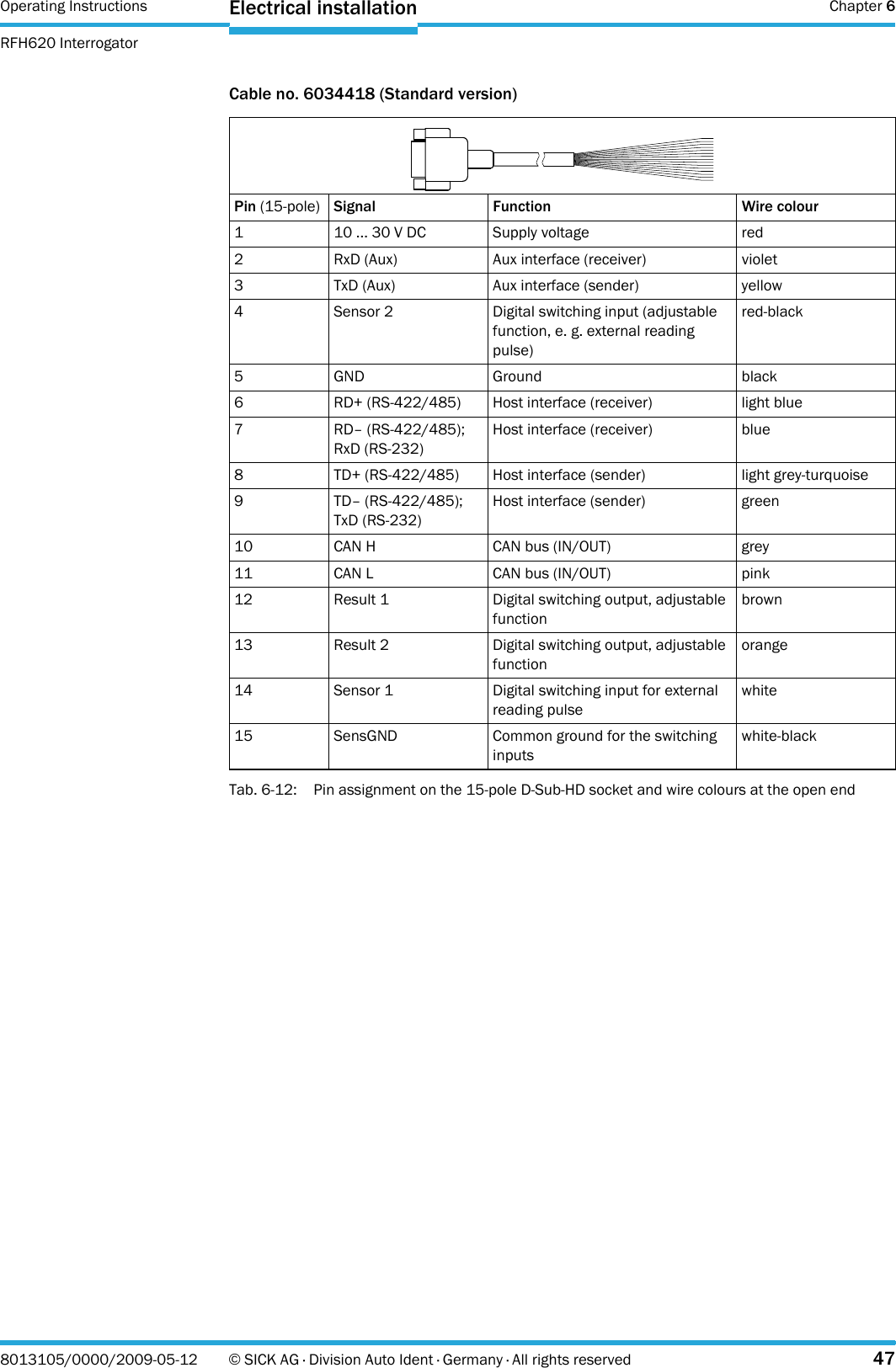
RFH620 User Manual
>
Users Manual
Contents
1.
Users Manual
2.
User Manual
Users Manual
Navigation menu
Upload a User Manual
Namespaces
Wiki Guide
HTML
PDF
Info
Views
User Manual
Discussion / Help
Navigation