Contents
- 1. Users Manual
- 2. User Manual
Users Manual

RFH620 Interrogator
Operating Instructions
OPERATING INSTRUCTIONS
RFH620
Radio Frequency Interrogator
(13.56 MHz)

Operating Instructions
Radio Frequency RFH620 Interrogator
2© SICK AG · Division Auto Ident · Germany · All rights reserved 8013105/0000/2009-05-12
Software Versions
Software Versions
Copyright
Trademark
Windows 2000TM, XPTM, VistaTM and Internet ExplorerTM are registered trademarks or trade-
marks of the Microsoft Corporation in the USA and other countries.
AcrobatTM ReaderTM is a trademark of Adobe Systems Incorporated.
Latest manual version
For the latest version of this manual (PDF), see www.sick.com.
Software/Tool Function Version
Interrogator RFH620 SICK firmware From v 1.00
Device Description
RFH620
Device-specific software module for SOPAS-ET confi-
guration software
From v 1.00
SOPAS-ET Configuration software From v 2.20
Copyright © 2009
SICK AG Waldkirch
Auto Ident, Reute Plant
Nimburger Strasse 11
79276 Reute
Germany

Operating Instructions
RFH620 Interrogator
Contents
8013105/0000/2009-05-12 © SICK AG · Division Auto Ident · Germany · All rights reserved 3
Table of contents
Figures and Tables............................................................................................................ 5
Abbreviations used ........................................................................................... 5
Tables................................................................................................................. 7
Figures ............................................................................................................... 8
1 Notes on this document................................................................................................... 9
1.1 Purpose of this document ................................................................................ 9
1.2 Target group ...................................................................................................... 9
1.3 Depth of information......................................................................................... 9
1.4 Used symbols ..................................................................................................10
2 For your safety.................................................................................................................11
2.1 Authorised users .............................................................................................11
2.2 Intended use ...................................................................................................12
2.3 General safety precautions and protection measures.................................13
2.4 Quick stop and quick restart ..........................................................................14
2.5 Environmental information.............................................................................14
3 Quick-Start .......................................................................................................................15
3.1 Preparing the interrogator for the quick start ...............................................15
3.2 Establishing connection with the interrogator ..............................................15
3.3 Performing the reading...................................................................................16
4 Product description.........................................................................................................19
4.1 Device versions ...............................................................................................19
4.2 Mounting and mode of operation of the interrogator...................................19
4.3 Scope of delivery.............................................................................................22
4.4 System requirements......................................................................................22
4.5 Product features and functions (overview) ...................................................22
4.6 Functions of the interrogator..........................................................................24
4.7 Control elements and indicators....................................................................27
5 Installation .......................................................................................................................31
5.1 Overview of installation sequence.................................................................31
5.2 Installation preparations ................................................................................31
5.3 Installation location ........................................................................................33
5.4 Installation of the interrogator .......................................................................33
5.5 Installing external components......................................................................33
5.6 Dismantling the interrogator ..........................................................................34
6 Electrical installation ......................................................................................................35
6.1 Overview of installation sequence.................................................................35
6.2 Electrical installation preparations ................................................................35
6.3 Electric connections and cables ....................................................................36
6.4 Performing electrical installation ...................................................................39
6.5 Pin assignment and wire colours of the assembled cables.........................45
7 Commissioning and configuration ...............................................................................49
7.1 Overview of the start-up procedure ...............................................................49
7.2 SOPAS-ET configuration software ..................................................................49
7.3 Establishing communication with the interrogator.......................................50
7.4 Initial commissioning ......................................................................................52
7.5 Default setting.................................................................................................55
8 Maintenance ....................................................................................................................57
8.1 Maintenance during operation.......................................................................57
8.2 Cleaning the housing ......................................................................................57
8.3 Checking the incremental encoder................................................................57
8.4 Replacing an interrogator...............................................................................57
9 Troubleshooting...............................................................................................................59
9.1 Overview of errors and malfunctions which could occur..............................59
9.2 Detailed malfunction analysis........................................................................59
9.3 Status protocol ................................................................................................60
9.4 SICK support....................................................................................................60

Operating Instructions
Radio Frequency RFH620 Interrogator
4© SICK AG · Division Auto Ident · Germany · All rights reserved 8013105/0000/2009-05-12
Contents
10 Technical data................................................................................................................. 61
10.1 Interrogator´s data sheet RFH620. .............................................................. 61
10.2 Interrogator´s dimensional drawings RFH620............................................. 63
11 Appendix .......................................................................................................................... 65
11.1 Overview of the Appendixes........................................................................... 65
11.2 Configuring the interrogator with command strings .................................... 65
11.3 Dimensional drawing accessories................................................................. 66
11.4 Supplementary documentation ..................................................................... 67
11.5 EC Declaration of Conformity......................................................................... 68
11.6 FCC authorisation ........................................................................................... 69

Operating Instructions Chapter
RFH620 Interrogator
Figures and Tables
8013105/0000/2009-05-12 © SICK AG · Division Auto Ident · Germany · All rights reserved 5
Figures and Tables
Abbreviations used
AM Amplitude Modulation
CAN Controlled Area Network. Field bus protocol on the basis of the CAN bus
CDB Connection Device Basic
CDM Connection Device Modular
CMC Connection Module Cloning
CMD Connection Module Display
CMF Connection Module Field bus
CMP Connection Module Power
DSFID Data Storage Format IDentifier
DSP Digital Signal Processor
EOF End Of Frame
ETX End Of Text
FCC Federal Communications Commission
HTML Hyper Text Markup Language (page description language in the internet)
IInput
IC Integrated Circuit
ID IDentification
IP Internet Protocol
ISO/IEC International Organisation for Standardisation / International Electrotechnical Commission
ITF Interrogator Talks First
LED Light Emitting Diode. Light emitting diode
LSB Least Significant Bit
MAC Medium Access Control
MSB Most Significant Bit
MTTF Mean Time To Failure
MTTR Mean Time To Repair
OOutput
PC Personal Computer
PID Process ID
PROM Programmable Read Only Memory. Programmable read only memory
RAM Random Access Memory. Random access memory
RF Radio Frequency
RFID Radio Frequency IDentification
ROM Read Only Memory. Read only memory (non-volatile)
RSSI Received Signal Strength Indication
RTF Rich Text Format (standardised document format with format description)
SD Secure Digital
SOF Start Of Frame
SOPAS-ET SICK Open Portal for Application and Systems Engineering Tool (PC software for Windows for confi-
guring the interrogator)
PLC Progammable Logic Controller
STX Start Of Text

Chapter Operating Instructions
Radio Frequency RFH620 Interrogator
6© SICK AG · Division Auto Ident · Germany · All rights reserved 8013105/0000/2009-05-12
Figures and Tables
TCP/IP Transmission Control Protocol/Internet Protocol
TID Tag IDentifier
UID Unique IDentification code

Operating Instructions Chapter
RFH620 Interrogator
Figures and Tables
8013105/0000/2009-05-12 © SICK AG · Division Auto Ident · Germany · All rights reserved 7
Tables
Tab. 1-1: Target group of this document ...........................................................................9
Tab. 2-1: Required qualification for commissioning the interrogator .......................... 11
Tab. 4-1: Variants of the interrogator RFH620 .............................................................. 19
Tab. 4-2: RFH620 interrogator´s scope of delivery ...................................................... 22
Tab. 4-3: Overview of the product features and functions of the interrogator............. 23
Tab. 4-4: Configurable functions of the interrogator...................................................... 26
Tab. 4-5: LED indications ................................................................................................. 27
Tab. 4-6: Meaning of the LEDs during activation of buttons ......................................... 28
Tab. 6-1: Electric connections to the interrogator with a fixed cable and connector
(standard version) ............................................................................................ 36
Tab. 6-2: Electric connections to the interrogator with connector unit
(Ethernet version) ............................................................................................ 36
Tab. 6-3: Standard version: Pin assignment on the 15-pole D-Sub-HD
cable connector ............................................................................................... 37
Tab. 6-4: Ethernet version: Pin assignment to the 4-pole M12 socket ....................... 38
Tab. 6-5: Ethernet version: Pin assignment on the 12-pole M12 plug ........................ 38
Tab. 6-6: Recommended maximum cable lengths, depending
on the selected data transfer rate .................................................................. 40
Tab. 6-7: Ratings for the switching inputs ..................................................................... 43
Tab. 6-8: Ratings for the switching outputs ................................................................... 44
Tab. 6-9: Pin assignment on the 4-pole M12 plug and the 6-pole RJ45 plug ............. 45
Tab. 6-10: Pin assignment on the 12-pole M12 socket and the 15-pole
D-Sub-HD plug .................................................................................................. 45
Tab. 6-11: Pin assignment on the 12-pole M12 socket and wire colours
at the open end ................................................................................................ 46
Tab. 6-12: Pin assignment on the 15-pole D-Sub-HD socket and wire colours
at the open end ................................................................................................ 47
Tab. 7-1: Default setting for the SOPAS-ET configuration software (excerpt) ............. 50
Tab. 7-2: Connection between PC with SOPAS-ET configuration software
and the interrogator ......................................................................................... 50
Tab. 10-1: Technical specifications of the interrogator RFH620..................................... 62
Tab. 11-1: Supplementary documentation ....................................................................... 67

Chapter Operating Instructions
Radio Frequency RFH620 Interrogator
8© SICK AG · Division Auto Ident · Germany · All rights reserved 8013105/0000/2009-05-12
Figures and Tables
Figures
Fig. 3-1: Register tab Quickstart .................................................................................... 16
Fig. 3-2: Advanced settings on the Transponder Communication register tab .......... 16
Fig. 3-3: Register tab tag access ................................................................................... 17
Fig. 4-1: Device view of the interrogator RFH620 (standard version) ......................... 20
Fig. 4-2: Device view RFH620 (Ethernet version) ......................................................... 21
Fig. 4-3: Standard version: Electric connections to the interrogator
with connection cable....................................................................................... 24
Fig. 4-4: Standard version: Electric connections to the interrogator
with connection cable by using a CDF600 bus connection module ............. 24
Fig. 4-5: Ethernet version: Electrical connections to the interrogator
with plug connector unit................................................................................... 25
Fig. 4-6: Micro SD memory card for storing the parameter set ................................... 29
Fig. 5-1: Example: Fixing the interrogator with bracket no. 2048551 ........................ 32
Fig. 6-1: Direction of rotation of the connector unit...................................................... 39
Fig. 6-2: Wiring the serial host data interfaces (RS-232 and RS-422 respectively)
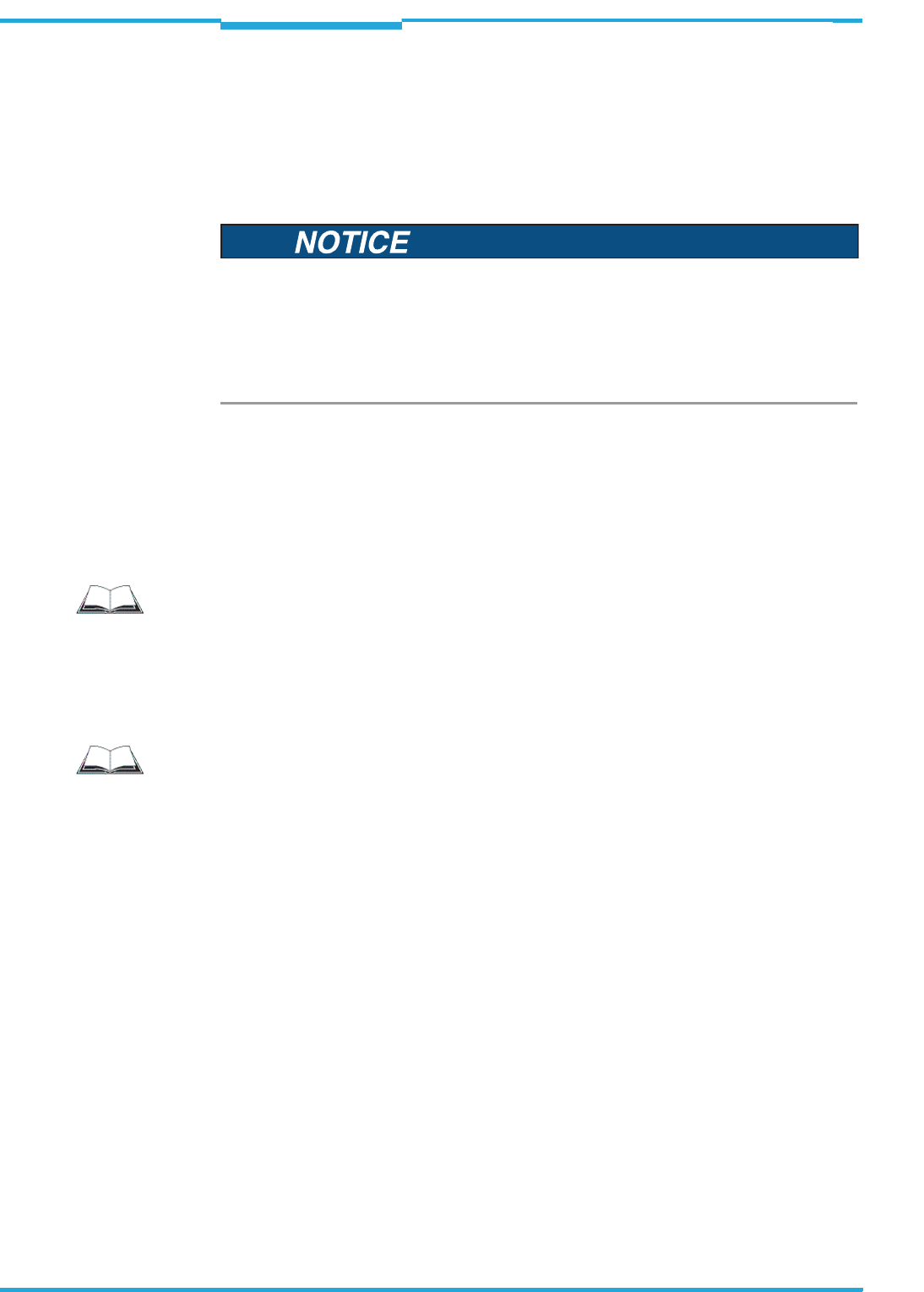
on the 15-pole D-Sub-HD plug ........................................................................ 40
Fig. 6-3: Function of the Ethernet interface .................................................................. 42
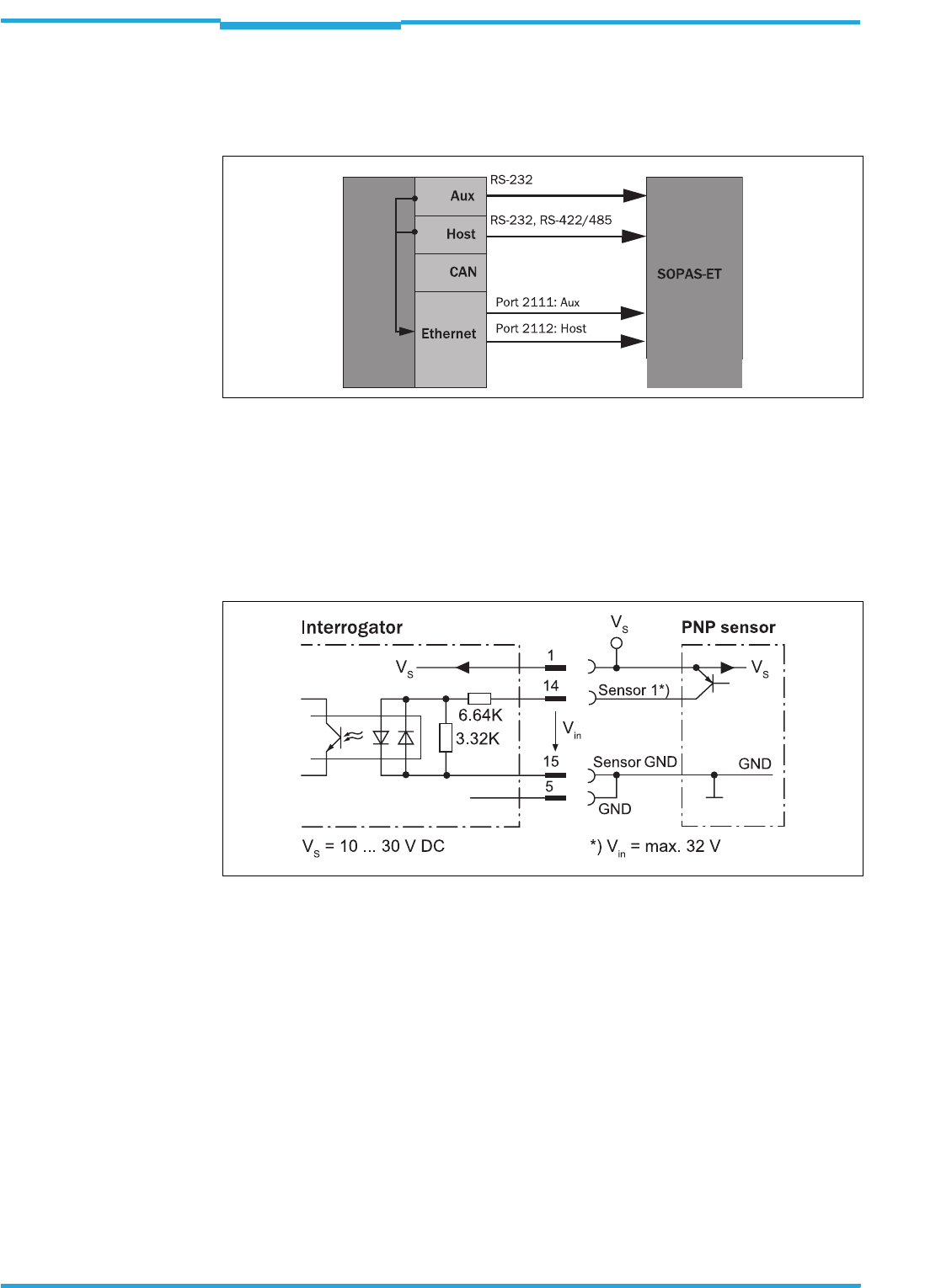
Fig. 6-4: Wiring "sensor 1" switching input on the 15-pole D-Sub-HD plug ................ 42
Fig. 6-5: Wiring "sensor 2" switching input on the 15-pole D-Sub-HD plug ................ 43
Fig. 6-6: Possible wiring of "result 1" switching output on the 15-pole
D-Sub-HD plug .................................................................................................. 44
Fig. 7-1: Configuration with SOPAS-ET and storage of the parameter set .................. 52
Fig. 10-1: Standard version: Dimensions of the interrogator (RFH620-1000001) ...... 63
Fig. 10-2: Ethernet version: Dimensions of the interrogator (RFH620-1001201) ....... 64
Fig. 11-1: Dimensions of the fixing bracket no. 2048551 ............................................ 66
Fig. 11-2: EC Declaration of Conformity for the interrogator
(page 1, scaled down version) ........................................................................ 68

Operating Instructions Chapter 1
RFH620 Interrogator
Notes on this document
8013105/0000/2009-05-12 © SICK AG · Division Auto Ident · Germany · All rights reserved 9
1Notes on this document
1.1 Purpose of this document
This document provides instructions for technical staff on the installation and operation of
the radio frequency interrogator of series RFH620 in the following versions:
• With the cable and connector (standard version)
• With connector unit (Ethernet version)
A summary of all device versions is shown in chapter 4.1 Device versions, page 19.
This document contains information for:
•Installation
• Electrical installation
• Commissioning and configuration
• Maintenance and replacement of the interrogator
•Troubleshooting
A step-by-step approach is taken for all tasks.
Important To simplify, the radio frequency interrogator RFH620 is described in these operating instruc-
tions as an interrogator or RFH620.
The description "interrogator" and "writing/reading device" are interchangeable. The de-
scription "interrogator" is used in these instructions. The description "transponder" and "tag"
are interchangeable. The description "transponder" is used in these instructions.
1.2 Target group
The target group of this document is persons assigned the following tasks:
Tab. 1-1: Target group of this document
1.3 Depth of information
This document contains all the information required for the installation, electrical installati-
on and commissioning of the interrogator at the installation location.
Configuration of the interrogator for application-specific reading conditions and the com-
missioning is carried out using the SOPAS-ET configuration software on a WindowsTM PC. The
SOPAS-ET configuration software contains an online help system to facilitate configuration.
Important Further information about the design of the interrogator as well as the RFID technology is
available at SICK AG, Auto Ident division. On the Internet at www.sick.com.
Tasks Target group
Installation, electrical installation,
maintenance, device replacement
Qualified staff, e.g., service technicians and factory electri-
cians
Commissioning and configuration Trained staff, e.g., technicians or engineers
Chapter 1 Operating Instructions
Radio Frequency RFH620 Interrogator
10 © SICK AG · Division Auto Ident · Germany · All rights reserved 8013105/0000/2009-05-12
Notes on this document
1.4 Used symbols
To gain easier access, some information in this documentation is emphasised as follows:
Notice!
Notice indicates a potential risk of damage or impair on the functionality of the interrogator
or other devices.
>Carefully read and follow the notice details!
Warning notice!
A warning notice indicates real or potential danger. This should protect you against acci-
dents.
The safety symbol next to the warning notice indicates why there is a risk of accident, e. g.,
due to electricity. The warning levels (DANGER, WARNING, CAUTION) indicate the serious-
ness of the risk.
>Carefully read and follow the warning notices!
Reference Italic script denotes a reference to further information.
Important This important note informs you about specific features.
Explanation An explanation provides background knowledge of technical nature.
Recommendation A recommendation helps you to carry out tasks correctly.
TIP A tip explains setting options in the SOPAS-ET configuration software.
PROJECT This type of script denotes a term in the user interface in the SOPAS-ET configuration soft-
ware.
A symbol indicates a button in the user interface of the SOPAS-ET configuration software.
There is a procedure which needs to be carried out. This symbol indicates standard opera-
ting procedures, which contain only one operational step or operational steps in warning no-
tices that do not have to be followed in any particular order. Operational instructions
comprising several steps are denoted using consecutive numbers.
Note
This symbol denotes a section, in which the operation steps with the SOPAS-ET configurati-
on software are described.
Important
This symbol indicates supplementary technical documentation.

Operating Instructions Chapter 2
RFH620 Interrogator
For your safety
8013105/0000/2009-05-12 © SICK AG · Division Auto Ident · Germany · All rights reserved 11
2For your safety
This chapter deals with your safety and that of the system operator.
>Read this chapter carefully before using the interrogator.
2.1 Authorised users
For correct and safe functioning, the interrogator must be installed, operated and main-
tained by sufficiently qualified staff.
Important Repairs to the interrogator should only be carried out by qualified and authorised SICK AG
service staff.
>The operating instructions should be made available to the end user.
>The end user should be briefed and urged to read the operating instructions by the
technicians.
The following qualifications are required for different activities:
Tab. 2-1: Required qualification for commissioning the interrogator
Tasks Qualification
Installation, maintenance • Practical technical training
• Knowledge of current health and safety regulations at the work-
place
• Basic knowledge of HF technology
Electrical installation, device
replacement
• Practical electrical training
• Knowledge of current electrical safety regulations
• Knowledge of start-up and operation of the device in each operati-
onal area (e. g. conveyor system)
• Basic knowledge of HF technology
Start-up and configuration • Basic knowledge of the WindowsTM operating system in use
• Basic knowledge of designing and setting up (addressing) Ethernet
connections for connecting the interrogator to the Ethernet
• Basic knowledge of working with an HTML browser (e. g. Internet
ExplorerTM) for using the online help
• Basic knowledge of data transfer
• Basic knowledge of RFID technology
• Basic knowledge of HF technology
Operation of the device in
each operational area
• Knowledge of start-up and operation of the device in each operati-
onal area (e. g. conveyor system)
• Knowledge of the software and hardware environment in each
operational area (e. g. conveyor system)

Chapter 2 Operating Instructions
Radio Frequency RFH620 Interrogator
12 © SICK AG · Division Auto Ident · Germany · All rights reserved 8013105/0000/2009-05-12
For your safety
2.2 Intended use
The interrogator RFH620 is an ISO/IEC-15693 compatible transponder printer/reader unit
for the close-up range (operating range of up to 16 cm), e. g., in a conveyor system.
The intended use of the interrogator results from the following description of the function:
• The interrogator is installed in a holder in a reading station.
• The interrogator transfers the reading data via the host interface to a superordinate
host computer for further processing.
• The interrogator is configured/operated using the SOPAS-ET configuration software
that runs on a standard client PC provided by the customer. In this connection, commu-
nication takes place via RS-232 or Ethernet.
• The Interrogator controls (locally), e. g., switches in the conveyor system via the digital
switching outputs.
Important Any warranty claims against SICK AG shall be deemed invalid in case changes are made to
the interrogator, e. g., opening the housing, this includes modifications during installation
and electrical installation or changes to the SICK software.
>The interrogator is only to be operated in ambient air temperature limit.
2.2.1 CE authorisation
The interrogator RFH620 fulfils the requirements of CE authorisation.
2.2.2 FCC authorisation
The interrogator RFH620 is in accordance with part 15 of FCC guidelines.
This device complies with Part 15 of the FCC Rules. Operation is subject to the following two
conditions:
• This device may not cause harmful interference, and
• this device must accept any interference received, including interference that may cau-
se undesired operation.
Any changes or modifications not expressly approved by the party responsible for compli-
ance could void the user's authority to operate this equipment.

Operating Instructions Chapter 2
RFH620 Interrogator
For your safety
8013105/0000/2009-05-12 © SICK AG · Division Auto Ident · Germany · All rights reserved 13
2.3 General safety precautions and protection measures
>Read the general safety precautions thoroughly and observe them during all operations
on the interrogator. Also observe the warning notices in each chapter of this document
before the standard operating procedures.
Electrical installation work
Important >Electrical installation must be performed by qualified staff only.
>Connect or release current linkages only under de-energised conditions.
>Wire cross sections and their correct shields have to be selected and implemented ac-
cording to valid engineering standards.
Risk of injuries due to electrical current!
The optional power supply module CMP400/CMP490 is connected to the power supply
(100 ... 250 V AC/50 ... 60 Hz) in the connection module CDM420.
>Observe current safety regulations when working with electrical equipment.

Chapter 2 Operating Instructions
Radio Frequency RFH620 Interrogator
14 © SICK AG · Division Auto Ident · Germany · All rights reserved 8013105/0000/2009-05-12
For your safety
2.4 Quick stop and quick restart
The interrogator can be switched on or off using the main switch for connection modules
CDB620 or CDM420 respectively.
2.4.1 Switching off the interrogator
>Switch off the power supply to the interrogator (via the connection module)
- or -
Unplug the 15-pole D-Sub-HD connector of the interrogator´s connection cable from
the connection module.
When the interrogator is switched off, the following data are lost:
• Application-specific parameter sets in the interrogator that were only saved temporarily
in the device
• The last reading result of the interrogator
• Daily operating hours counter of the interrogator
2.4.2 Switching the interrogator back on
>Switch the power supply to the interrogator (via the connection module) back on
- or -
Re-connect the 15-pole D-Sub-HD connector of the interrogator´s connection cable to
the connection module.
The interrogator starts up using the most recent permanently saved configuration. The
daily operating hours counter is reset.
2.5 Environmental information
The interrogator has been constructed with minimum environmental pollution in mind. Ex-
cluding the housing, the interrogator does not contain any materials made of silicone.
2.5.1 Energy requirement
The interrogator serial RFH620 consumes the following energy:
• Typical 5 W in 10 ... 30 V DC (in unwired switching outputs)
2.5.2 Dispose of the device after decommissioning
Currently, SICK AG will not accept the return of any devices which can no longer be operated
or repaired.
>Inoperable or irreparable devices must be disposed of in an environmentally friendly
manner and in accordance with valid country-specific waste disposal guidelines.
The design of the interrogator allows for its separation as recyclable secondary raw materi-
als and hazardous waste (electronic scrap).

Operating Instructions Chapter 3
RFH620 Interrogator
Quick-Start
8013105/0000/2009-05-12 © SICK AG · Division Auto Ident · Germany · All rights reserved 15
3Quick-Start
3.1 Preparing the interrogator for the quick start
The interrogator can be operated quickly and easily using the supplied SOPAS-ET configura-
tion software.
Among others, the software offers the following options:
• Fast connection with the interrogator
• Easy access to the transponder data and display of the reading results on two clear re-
gister tabs of the configuration software
System requirements for using the SOPAS-ET configuration software
See chapter 7.2.2 System requirements for the SOPAS-ET configuration software, page 49
Additional accessories required (not in the scope of delivery)
• Connection module CDB620 or CDM420
• For the Ethernet version of the interrogator: Connection cable for data and function in-
terfaces (see ordering designations of the product information "Interrogator RFH620")
• 3-wire RS-232 data cable (null modem cable), no. 2014054 for the connection of the
PC with the connection module
- or -
To connect an Ethernet version of the interrogator to the PC's Ethernet interface
(For corresponding cable, see ordering designations of the product information "Inter-
rogator RFH620" Nr. 8013102)
Establish an electric connection to the interrogator
1. Connect the interrogator to connection module CDB620/CDM420.
2. Switch on the power supply for CDB620/CDM420.
3. Switch on the PC for the configuration and install and start the supplied SOPAS-ET con-
figuration software.
4. Connect the PC to the interrogator.
To achieve this, connect the PC using a 3-wire RS-232 data cable (null modem cable)
to the "Aux“ connection in CDB620/CDM420.
- or -
In Ethernet version, connect the PC to the interrogator's Ethernet interface.
For detailed instructions, see chapter 5 Installation, page 31 and chapter 6 Electrical in-
stallation, page 35.
3.2 Establishing connection with the interrogator
>Communicate with the interrogator according to the selected data interface (RS-232 or
Ethernet) (see chapter 7.3 Establishing communication with the interrogator,
page 50).
TIP To establish a connection quickly and easily via the Ethernet, the SOPAS-ET configuration
software has a CONNECTION WIZARD in the menu TOOLS.
Chapter 3 Operating Instructions
Radio Frequency RFH620 Interrogator
16 © SICK AG · Division Auto Ident · Germany · All rights reserved 8013105/0000/2009-05-12
Quick-Start
3.3 Performing the reading
Fig. 3-1: Register tab Quickstart
Determining the transponder inventory
1. Ensure that the relevant transponder types on the register tab TAG PROZESSING are ac-
tivated.
Fig. 3-2: Advanced settings on the Tag Prozessing register tab
2. Carry out test reading with transponder.
To this end, hold the transponder in the reading area of the interrogator and trigger the
reading by clicking on START.
The unique ID, manufacturer and IC type of the detected transponder are registered.
The signal-to-noise ratio (RSSI: Received Signal Strength Indication) is displayed in the
display field RSSI respectively.
3. In order to end the reading process, click on STOP.
Note
An inventory of all transponders within the reading range of the interrogator is determined
via the register tab QUICKSTART of the SOPAS-ET configuration software:
PROJECT TREE, RFH620, register tab QUICKSTART
Operating Instructions Chapter 3
RFH620 Interrogator
Quick-Start
8013105/0000/2009-05-12 © SICK AG · Division Auto Ident · Germany · All rights reserved 17
Optimising the reading conditions
If no transponder is displayed or if you wish to increase the RSSI value, the reading can be
repeated by taking the following measures:
1. Correct or optimise the parameter values, where necessary, via the SOPAS-ET configu-
ration software.
2. In order to optimise the RSSI value, reduce the distance between the interrogator and
the transponder.
Reading/writing the user data of the transponder
The user data of a transponder can be read/written via the register tab TAG ACCESS of the
SOPAS-ET configuration software:
Important When accessing, the transponder must be located in the reading area of the interrogator.
>Select a transponder from the list on the register tab QUICKSTART and click on ACCESS.
The register tab TAG ACCESS opens.
The user data of the transponder are read and displayed.
Fig. 3-3: Register tab Tag access
>In order to change the user data of the transponder, overwrite corresponding values
block by block and transmit them to the transponder by clicking on BLOC WRITING.

Chapter 3 Operating Instructions
Radio Frequency RFH620 Interrogator
18 © SICK AG · Division Auto Ident · Germany · All rights reserved 8013105/0000/2009-05-12
Quick-Start

Operating Instructions Chapter 4
RFH620 Interrogator
Product description
8013105/0000/2009-05-12 © SICK AG · Division Auto Ident · Germany · All rights reserved 19
4Product description
This chapter describes the design, the features and the functions of the interrogator
RFH620.
>For installation, electrical installation and start-up assistance as well as for the applica-
tion-specific configuration of the interrogator using the SOPAS-ET configuration soft-
ware, please read this chapter prior to carrying out any of the tasks.
4.1 Device versions
Among others, the interrogator RFH620 is available in the following versions:
Tab. 4-1: Variants of the interrogator RFH620
Important The following are available depending on the connection (design):
•Standard version (cable with plug)
– RS-232, RS-422/485, CAN, two digital switching inputs, two digital switching out-
puts, power supply
•Ethernet version (revolving connector unit)
– Connector 1: Ethernet
– Connector 2: RS-232, RS-422/485, CAN, one digital switching input, power supply
4.2 Mounting and mode of operation of the interrogator
The interrogator RFH620 is an ISO/IEC-15693 compatible transponder writing/reading de-
vice with integrated antenna for the close-up range. All the components are located in a
housing suitable for the industry. Depending on the version, the electric connection of the
interrogator takes place via a cable with a connector or a revolving connector unit with two
connections.
The interrogator RFH620 is an intelligent sensor for automatic and non-contact detection
of RFID transponders. In principle, the transponder can be detected on any location of still
or moving objects in a conveyor system. The reading range expands through the combinati-
on of many devices.
Order no. Type Version Connection (design)
1044838 RFH620-1000001 Standard version Cable with plug
1044839 RFH620-1001201 Ethernet version Connector unit on the
device
Chapter 4 Operating Instructions
Radio Frequency RFH620 Interrogator
20 © SICK AG · Division Auto Ident · Germany · All rights reserved 8013105/0000/2009-05-12
Product description
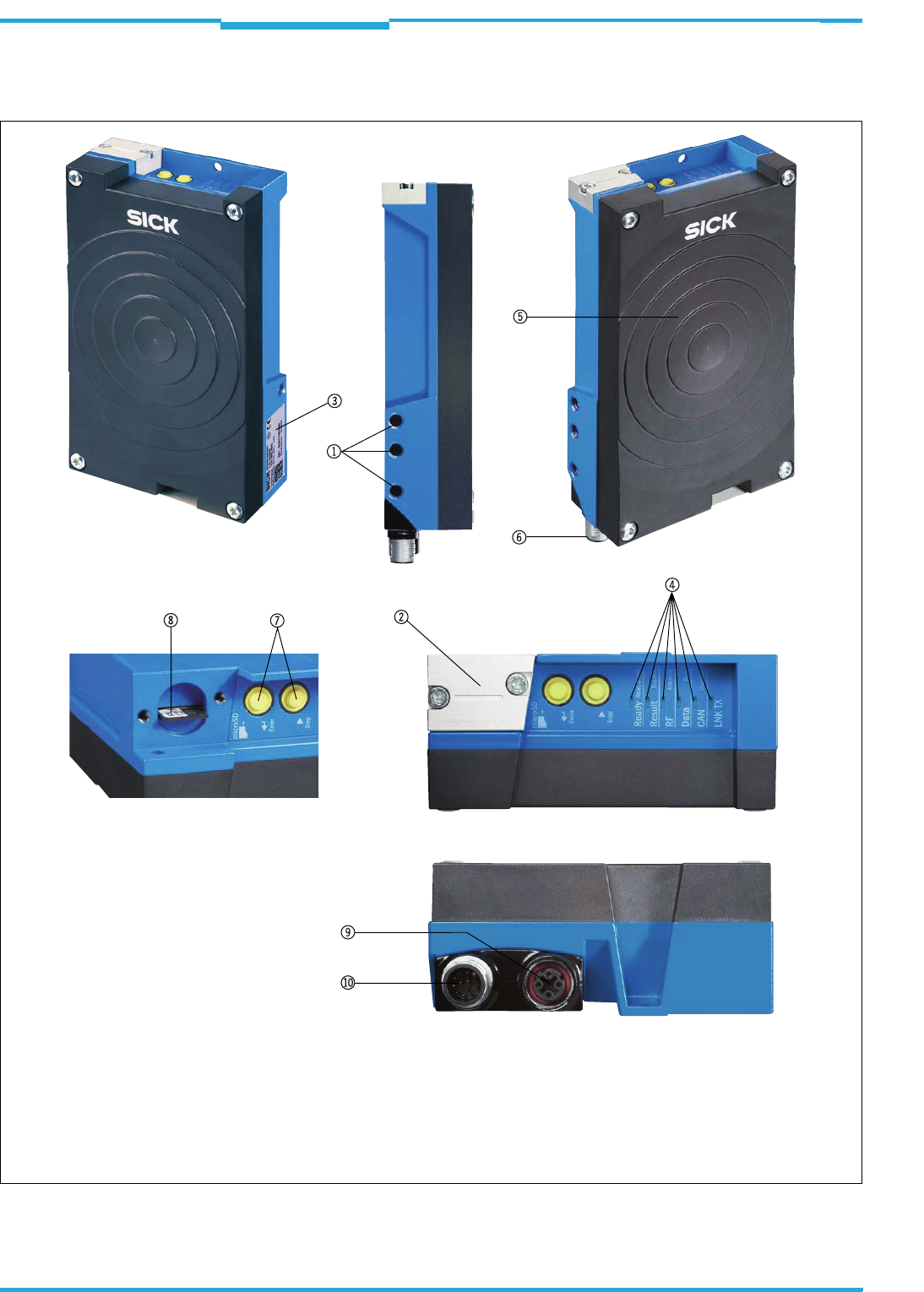
4.2.1 Device view RFH620 (standard version)
Fig. 4-1: Device view of the interrogator RFH620 (standard version)
1Blind hole thread M6 for fastening
2Cover for Micro-SD card slot
3Type plate
4LEDs for status indicator
5Antenna
6Cable with plug
7Button for function selection/activation
8Micro SD memory card (optional)
Operating Instructions Chapter 4
RFH620 Interrogator
Product description
8013105/0000/2009-05-12 © SICK AG · Division Auto Ident · Germany · All rights reserved 21
4.2.2 Device view RFH620 Ethernet version
Fig. 4-2: Device view RFH620 (Ethernet version)
1Blind hole thread M6 for fastening
2Cover for Micro-SD card slot
3Type plate
4LEDs for status indicator
5Antenna
6Revolving connector unit
7Button for function selection/activation
8Micro SD memory card (optional)
94-pole M12 jack (Ethernet connection)
bl 12-pole M12 plug
Chapter 4 Operating Instructions
Radio Frequency RFH620 Interrogator
22 © SICK AG · Division Auto Ident · Germany · All rights reserved 8013105/0000/2009-05-12
Product description
4.3 Scope of delivery
Delivery of the interrogator RFH620 includes the following components:
Tab. 4-2: RFH620 interrogator´s scope of delivery
Important The Micro-SD memory card is not included in the scope of delivery.
Important For save operation of the Micro-SD memory card, use only SICK approved memory card.
Contents of the CD-ROM
•"SOPAS-ET": Configuration software for WindowsTM PCs with integrated online help sys-
tem (HTML files)
•Operating instructions RFH620: PDF version in German and English as well as further
publications of other SICK devices
•Product information RFH620: PDF version in German and English including ordering in-
formation for the interrogator and accessories
•"Acrobat Reader": Freely available PC software for reading PDF files
Important The current versions of publications and programs on the CD-ROM can also be downloaded
at www.sick.com.
4.4 System requirements
General system requirements are derived from the interrogator's technical data (see
chapter 10 Technical data, page 61).
The requirements and conditions for Installation, Electrical installation as well as
Commissioning and configuration are summarised in the respective chapters.
4.5 Product features and functions (overview)
Piece Components Comment
1 Interrogator RFH620 depending on version
1 Notes on device with electrical connec-
tion diagrams as primary information
Included in the device packaging of the
interrogator RFH620
1 CD-ROM "Manuals & Software Auto
Ident"
Operating Instructions RFH620 in Ger-
man and/or English, in printed form
Optional, depending on the number of
issues explicitly ordered upon purchase
Important
An overview of in-stock installation accessories, connection modules, cables and connec-
tors, transponder as well as memory media (see chapter 11.4 Supplementary documenta-
tion, page 67) is available in the product information "Interrogator RFH620".
Interrogator RFH620 • 13.56 MHz ISO/IEC-15693 compatible RFID writing/reading device
• Compact, industry-type design with integrated antenna
• Connection technology for all current field bus and network concepts
• Application-specific operation mode: Command, trigger and freewheel mode
• EDP operating system with SOPAS operating software and additional script functionality
• Far-ranging internal and external diagnosis functions (RDT400, not available for market launch
in May 09. More information on request.)

Operating Instructions Chapter 4
RFH620 Interrogator
Product description
8013105/0000/2009-05-12 © SICK AG · Division Auto Ident · Germany · All rights reserved 23
Tab. 4-3: Overview of the product features and functions of the interrogator
Customer value • Reliable identification
• Effective safe investment
• Easy integration
•High functionality
• Maintenance-free
• Compatible SICK connection technology
User safety and convenience • Robust, compact metal housing, CE mark, FCC authorisation
• Automatic self-test on system start-up
• Diagnosis tools for system setup and system (remote) monitoring
• Configurable reading data display in two reading result formats
• Operational data retrieval, error code display on request in case of errors
• Test string function (heartbeat), capable of being activated, for signalling readiness for operation
• Password-protected configuration mode
• In addition, secured configured parameter values (cloning) on a Micro SD memory card (can be
removed in the case of interrogator replacement)
• Future proof due to firmware update (flash PROM) via data interface
• Future-proof SOPAS-ET configuration software
• Low current consumption
• Extended power supply range
Convenient operation/configura-
tion
• Configuration (online/offline) using the SOPAS-ET configuration software (incl. help system)
• 2 buttons on the device for calling up preset functions without connecting a PC
• Status indicators via LEDs
• Beeper, which can be switched off, to confirm device functioning
Reading pulse • Pulse sources for start: switching inputs; data interface (command); automatic cycle; CAN
• Pulse sources for stop: reading pulse source, switching inputs, command, timer, condition
• Freewheel mode
RFID evaluation • All current ISO/IEC-15693 compatible transponder
Data processing • Manipulation of the output of the reading data via event-dependent evaluation conditions
Data communication • Host interface: two configurable data output formats, switchable to different physical interfaces,
parallel operation possible
• Aux interface: fixed data output format, switchable to different physical interfaces, parallel ope-
ration possible
Electrical interfaces • Host interface: RS-232, RS-422/485 (data format and protocol can be configured) and Ethernet
or CAN
• Aux interface: RS-232 (fixed data format, data transfer rate and protocol) and Ethernet
• CAN interface for integration into the SICK-specific CAN-SENSOR network
• Digital switching inputs
– Standard version: two digital switching inputs for external reading pulse sensor(s), using opto-
coupler
– Ethernet version: one digital switching input on the device
• Digital switching outputs
– Standard version: two digital switching outputs for signalling definable results in the reading
process (reading result status)
– Ethernet version: no digital switching output on the device
Connection technology (design) • Standard version: Cable with 15-pole D-Sub-HD connector
• Ethernet version: revolving connector unit on the device with two M12 circular connectors
• Optional connection module CDB620/CDM420 for connection to the host computer (stand-alo-
ne) and for integrating into the SICK-specific CAN-SENSOR network
• Optional bus connection module CDF600 for PROFIBUS-DP
Chapter 4 Operating Instructions
Radio Frequency RFH620 Interrogator
24 © SICK AG · Division Auto Ident · Germany · All rights reserved 8013105/0000/2009-05-12
Product description
4.6 Functions of the interrogator
In order to control the read operation, external sensors deliver information via the reading
pulse. The reading results are output to the interrogator´s data interfaces and are forwar-
ded to a host/PC.
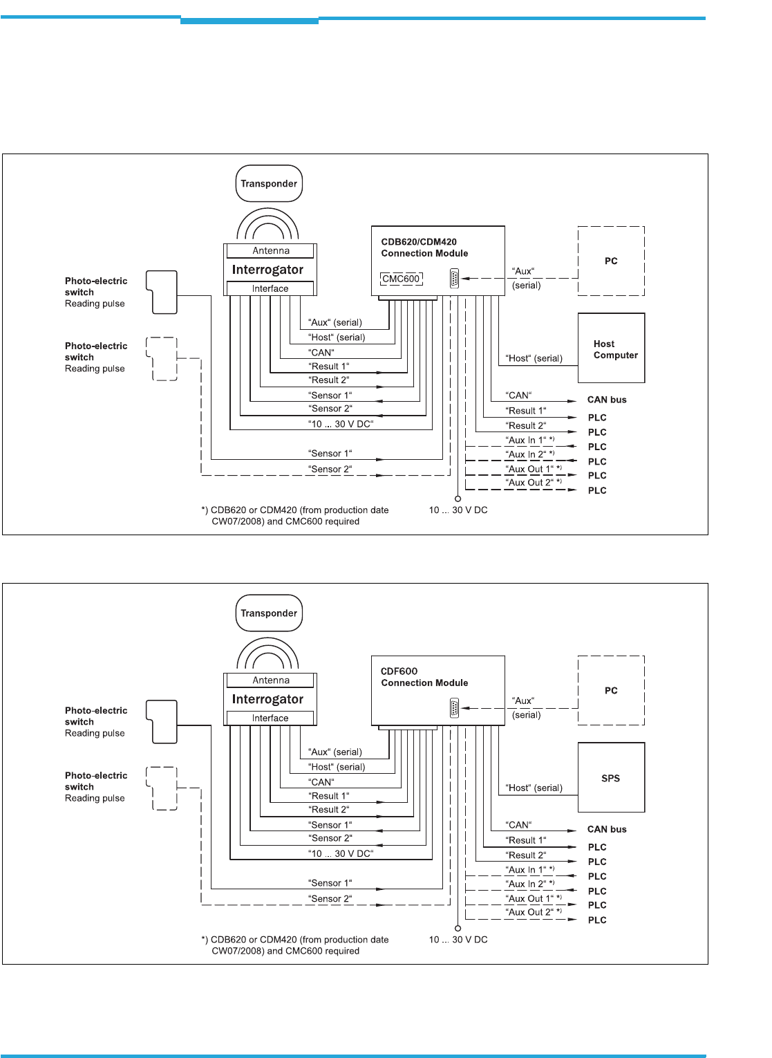
Fig. 4-3: Standard version: Electric connections to the interrogator with connection cable
Fig. 4-4: Standard version: Electric connections to the interrogator with connection cable by using a CDF600 bus connection
module
Operating Instructions Chapter 4
RFH620 Interrogator
Product description
8013105/0000/2009-05-12 © SICK AG · Division Auto Ident · Germany · All rights reserved 25
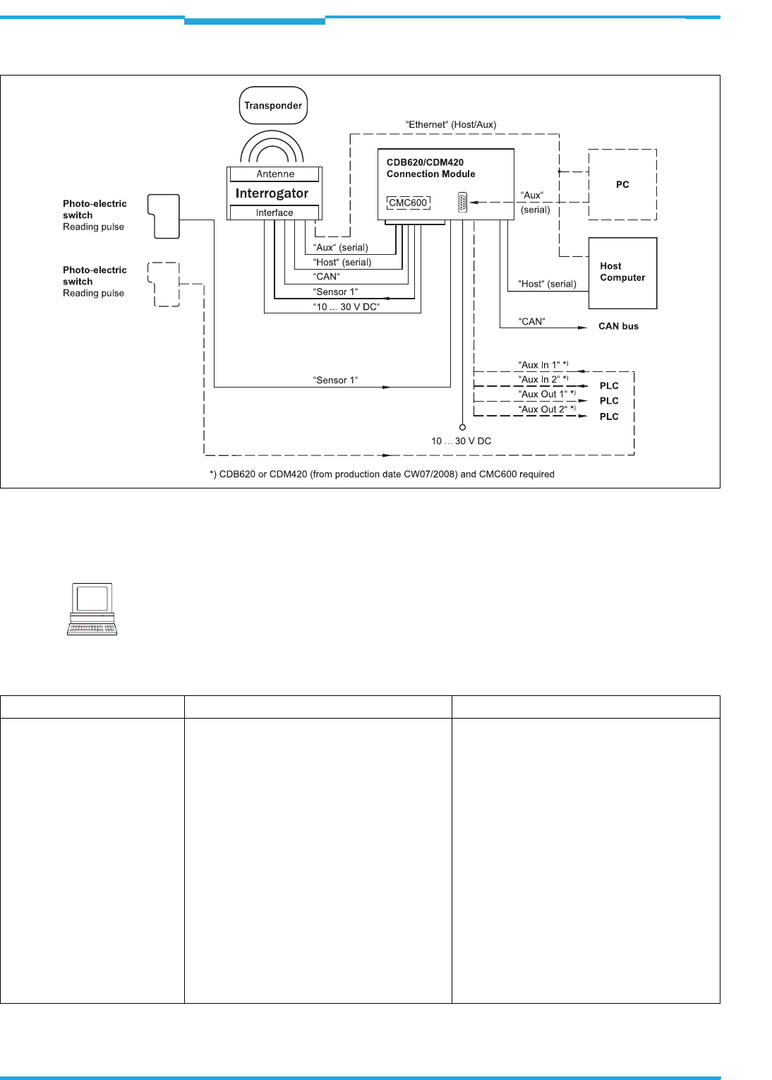
Fig. 4-5: Ethernet version: Electrical connections to the interrogator with plug connector unit
The detailed wiring of the interrogator and the connections to the host/PC and to the exter-
nal sensors is described in chapter 6 Electrical installation, page 35.
Note
Among other things, the following functions can be configured using the SOPAS-ET configu-
ration software:
Function Description Configuration with SOPAS-ET
Object trigger control In order to start an object-related reading pro-
cess, the interrogator requires an appropriate
external signal (trigger source) for reporting an
object in the reading area. As standard, the start
signal is emitted via an external reading pulse
sensor (e. g. photoelectric reflex switch). As soon
as an object has passed the reading pulse sen-
sor, a time window opens in the interrogator
("reading gate") for the reading process.
Alternatively, a command activates the reading
process via a data interface or the CAN-SENSOR
network. In Automatic Cycle mode, the actual
interrogator generates the reading gate inter-
nally with an adjustable mark-space ratio.
The reading pulse can be ended in a number of
ways: With external triggering by the reading
pulse source or a command, internally by a timer
or an evaluation condition to be met.
PROJECT TREE, RFH620, PARAMETER, OBJECT
TRIGGER CONTROL

Chapter 4 Operating Instructions
Radio Frequency RFH620 Interrogator
26 © SICK AG · Division Auto Ident · Germany · All rights reserved 8013105/0000/2009-05-12
Product description
Tab. 4-4: Configurable functions of the interrogator
Data processing The output time in the reading process, with
regard to the reading pulse start, can be confi-
gured using the SOPAS-ET configuration soft-
ware.
•PROJECT TREE, RFH620, PARAMETER, DATA
PROCESSING, OUTPUT CONTROL
•PROJECT TREE, RFH620, PARAMETER, DATA
PROCESSING, EVALUATION CONDITIONS
Output format The reading result is displayed via selectable
physical interfaces. Two different output formats
(telegrams) can be defined for this task, one for-
mat for "No Read" and one for the heartbeat
(signalisation of readiness).
PROJECT TREE, RFH620, PARAMETER, DATA PRO-
CESSING, OUTPUT FORMAT
Network / interfaces / IOs All important interfaces for displaying the rea-
ding results are available on the interrogator.
Several devices can be connected to each other
via the CAN bus in the SICK-specific CAN-SEN-
SOR network.
PROJECT TREE, RFH620, PARAMETER, NETWORK /
INTERFACES / IOS register tab NETWORK OPTIONS
Data interfaces Depending on the version, the following data
interfaces are available on the interrogator:
• Host interface (RS-232 or RS-422/485 and
Ethernet host port): Preparation of the reading
result for further processing by the host pro-
cessor
• Auxiliary interface (RS-232 and Ethernet aux
port): Reading diagnosis or host interface mo-
nitoring
• CAN: Networking of several devices
•PROJECT TREE, RFH620, PARAMETER,
NETWORK / INTERFACES / IOS, SERIAL
•PROJECT TREE, RFH620, PARAMETER,
NETWORK / INTERFACES / IOS, ETHERNET
•PROJECT TREE, RFH620, PARAMETER,
NETWORK / INTERFACES / IOS, CAN
Digital inputs For example, the external sensor for the object
triggering (photoelectric reflex switch) can be
connected to the digital switching inputs.
Important
The connection "sensor 2" is only available on
the standard version of the interrogator. For the
Ethernet version of the interrogator, this input is
only available with the connection module
CDB620/CDM420 in combination with the para-
meter memory module CMC600.
PROJECT TREE, RFH620, PARAMETER, NETWORK /
INTERFACES / IOS, DIGITAL INPUTS
Digital outputs With certain events in the reading process (e. g.
for unsuccessful reading "No Read"), two inde-
pendent switch signals, which can be used to
display the event status, can be generated at
both digital outputs.
Important
The switching outputs "result 1" and "result 2"
are only available on the standard version of the
interrogator. For the Ethernet version of the
interrogator, the two outputs are only available
with the connection module CDB620/CDM420
in combination with the parameter memory
module CMC600.
PROJECT TREE, RFH620, PARAMETER, NETWORK /
INTERFACES / IOS, DIGITAL OUTPUTS
Function Description Configuration with SOPAS-ET
Operating Instructions Chapter 4
RFH620 Interrogator
Product description
8013105/0000/2009-05-12 © SICK AG · Division Auto Ident · Germany · All rights reserved 27
4.7 Control elements and indicators
4.7.1 User interface
The interrogator is configured application-specifically using the SOPAS-ET configuration
software (see chapter 7.1 Overview of the start-up procedure, page 49). For this purpose,
the software runs on a PC, which must be connected to one of the two data interfaces (aux
interface: Ethernet or RS-232, host interface: RS-232/RS-422/485 or Ethernet) of the in-
terrogator.
As an alternative to the SOPAS-ET configuration software, command strings are available,
upon which the user interface of the SOPAS-ET configuration software is based (see
chapter 11.2 Configuring the interrogator with command strings, page 65).
In case of an error, start-up and diagnosis can be carried out via the SOPAS-ET configuration
software. The interrogator operates fully automated in normal operation.
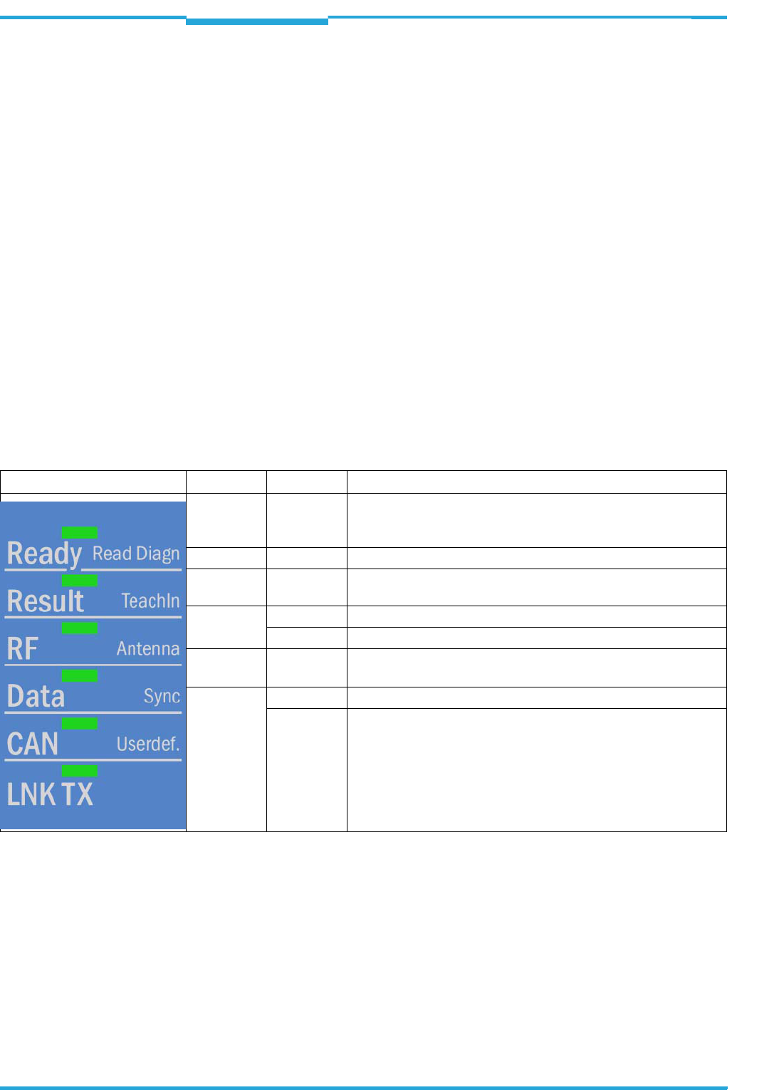
4.7.2 LEDs on the interrogator's housing
The interrogator's housing has six LEDs that display the operating status, the RF activity, the
status of the reading result as well as transfer to the RS-232/RS-422/485, CAN and Ether-
net interfaces.
In reading operation the LEDs indicate the following:
Tab. 4-5: LED indications
Important The "result" LED is coupled with none of the two digital switching outputs "result 1" or
"result 2".
LED Colour Denotation
Ready green • Lights up constantly when system is ready
• Goes out when parameter values are being uploaded from or
downloaded to the interrogator respectively
Result green • Lights up after a successful read (Good Read, 100 ms)
RF green • Lights up when the antenna field is switched on (depends on the
reading pulse)
Data green • Flickers during data transfer via the serial host interface (RxD)
yellow • Flickers during data transfer via the serial host interface (TxD)
CAN green • Lights up when the CAN interface is switched on
• Flickers during the data transfer via the CAN interface
LNK TX green • Flickers during data transfer via the Ethernet interface
yellow • Lights up when the physical Ethernet connection is established
Chapter 4 Operating Instructions
Radio Frequency RFH620 Interrogator
28 © SICK AG · Division Auto Ident · Germany · All rights reserved 8013105/0000/2009-05-12
Product description
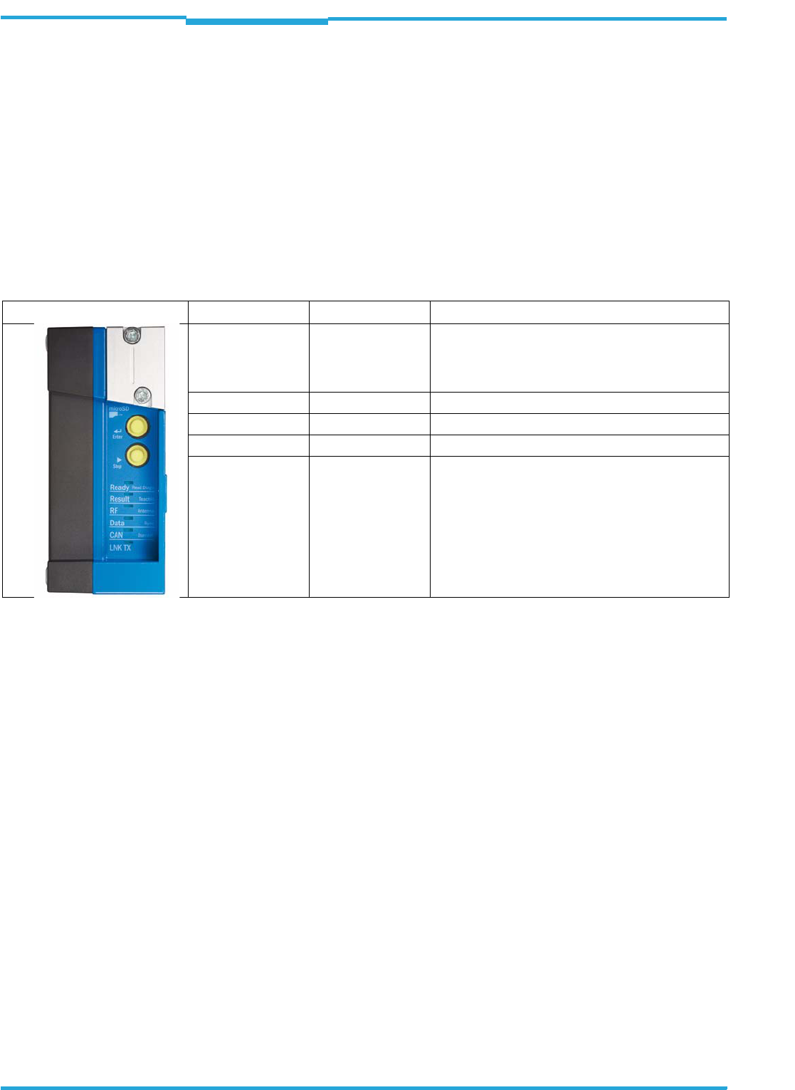
4.7.3 Buttons on the interrogator's housing
There are two yellow buttons on the interrogator´s housing in the LED area (see
chapter 4.2.1 Device view RFH620 (standard version), page 20). You can call up predefi-
ned functions via these buttons.
After changing to the button operating mode, you can select any one function by repeatedly
pressing the step button (b) respectively. The selected function is then activated and deac-
tivated with the enter button (p) respectively.
The selected function is shown via the corresponding LED below the buttons.
The functions "TeachIn", "Antenna", "Sync" und "Userdef." cannot be called up at the mo-
ment.
When using both of buttons, the display of the LEDs have different meanings other than in normal reading operation:
Tab. 4-6: Meaning of the LEDs during activation of buttons
Use of the buttons
In order to use one of the possible function with the buttons, do as follows:
1. Press the enter button (p) for approx. 3 seconds.
The interrogator stops the current reading operation, switches off the LEDs and
changes to the button operating mode. The bar code scanner ignores all the other ex-
ternal reading pulses with immediate effect. No reading results are displayed via the
host interface.
The beeper confirms this process with an ascending melody.
The "Read Diagn" function is pre-selected as first function (LED flashes slowly).
2. Press the enter button (p) once to start the selected function.
The LED flashes faster and the beeper confirms the start with two sounds.
3. Press the enter button (p) again to stop the selected function.
The LED flashes more slowly again and the beeper confirms the end with two sounds.
4. In order to return from the button operating mode to the reading operation, press the
enter button (p) again for approx. 3 seconds.
The beeper confirms the change with a descending melody.
The LED "Ready" lights up again.
The interrogator is ready for reading again and waits for a reading pulse.
LED Colour Function
Read Diagn green Flashes slowly: the function "reading diagnosis" is
selected
Flashes swiftly: the function "reading diagnosis" is
started
TeachIn green (momentarily not available)
Antenna green (momentarily not available)
Sync green (momentarily not available)
Userdef. yellow (momentarily not available)
Operating Instructions Chapter 4
RFH620 Interrogator
Product description
8013105/0000/2009-05-12 © SICK AG · Division Auto Ident · Germany · All rights reserved 29
Further behaviour of the interrogator when operated by buttons
• Changing into button operating mode is only possible if no other user is logged onto the
interrogator for changing the parameters via the SOPAS-ET configuration software. If
this is the case, however, the beeper gives a descending melody when trying to change
into the button operating mode. Furthermore, the interrogator remains in reading ope-
ration.
• In case a user logs onto the interrogator in button operating mode, the interrogator lea-
ves the button operating mode and restarts the reading operation. The beeper confirms
the change with a descending melody.
• If no function is started in button operating mode or if no button operation can be per-
formed after using a function, the interrogator automatically returns to the reading ope-
ration after 30 seconds. The beeper confirms the change with a descending melody.
• The interrogator terminates an activated continuous function 5 minutes after start. It
returns to reading operation automatically. The beeper confirms the change with a de-
scending melody.
• You cannot switch off or turn down the beeper in button operating mode.
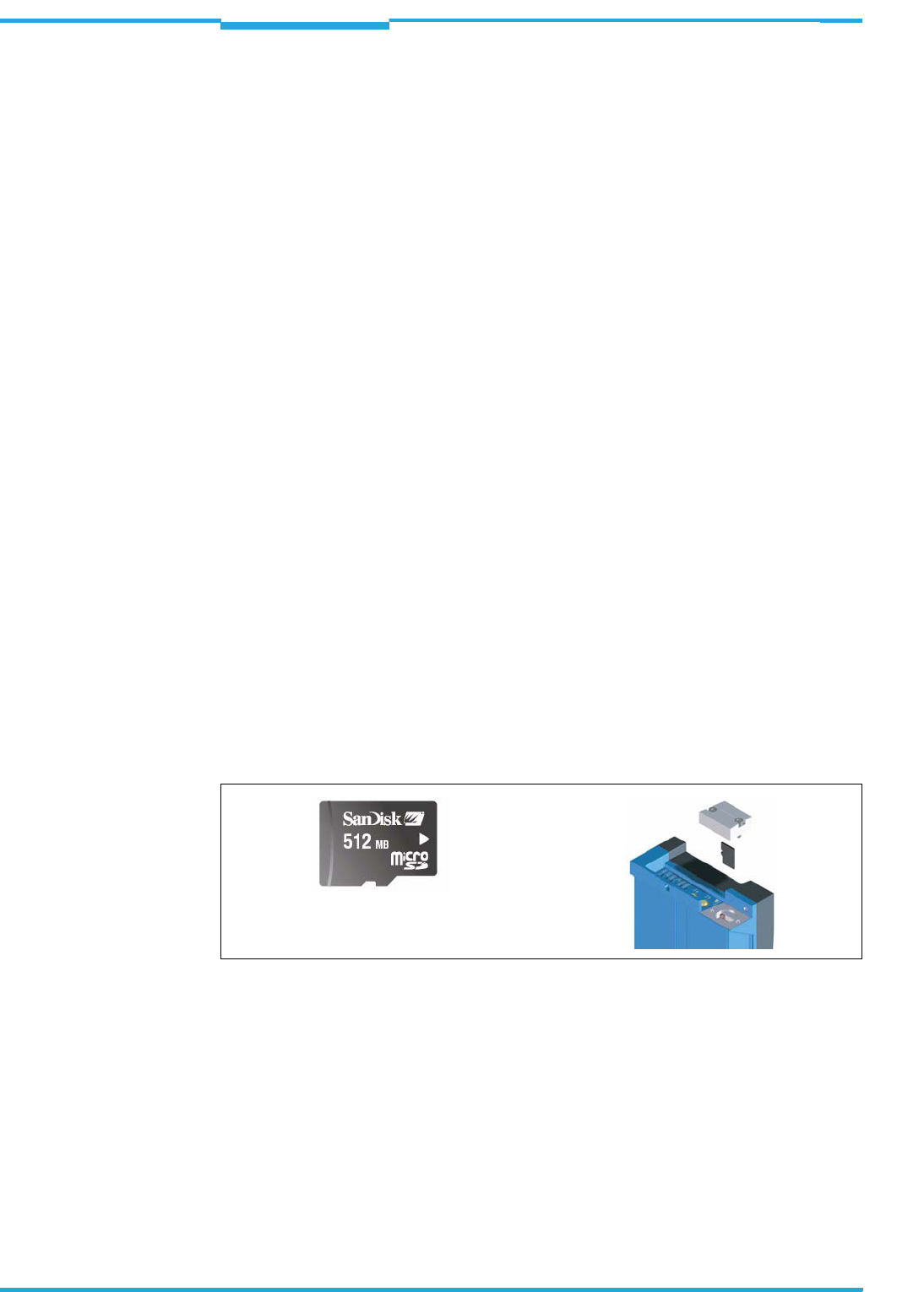
4.7.4 Parameter set on the Micro SD memory card (optional)
The interrogator stores configured parameter values in its internal PROM as well as on the
Micro SD memory card (cloning), provided that this card has been inserted into the interro-
gator. If the interrogator needs to be replaced, the memory card enables easy and quick
transfer of the parameter set to the new device (see chapter 8.4 Replacing an interrogator,
page 57).
Important In order to avoid data loss, the Micro SD memory card may only be removed and inserted
into the new device after the respective interrogator has been switched off and de-ener-
gized. When inserting the memory card, make sure that the card's notches point to the di-
rection of the two yellow keys.
The memory card is located behind a silver cover attached to the interrogator.
Fig. 4-6: Micro SD memory card for storing the parameter set
Important To maintain the enclosure rating IP 67, the cover has to be installed and screwed together
tightly. Width across flats WAF 2.5.
As an alternative to the Micro SD memory card in the interrogator, the external, optional pa-
rameter memory module CMC600 in connection module CDB620/CDM420 may also be
used for storing the parameter set. If both the Micro SD memory card and the parameter
memory module CMC600 are available, the interrogator loads the parameter set from
CMC600.

Chapter 4 Operating Instructions
Radio Frequency RFH620 Interrogator
30 © SICK AG · Division Auto Ident · Germany · All rights reserved 8013105/0000/2009-05-12
Product description

Operating Instructions Chapter 5
RFH620 Interrogator
Installation
8013105/0000/2009-05-12 © SICK AG · Division Auto Ident · Germany · All rights reserved 31
5Installation
5.1 Overview of installation sequence
This chapter describes the installation sequences for the interrogator and its external com-
ponents.
The typical installation sequences are listed below:
• Select the installation location for the interrogator
• Install the interrogator
• Install connection module CDB620 or CDM420
• Connect the interrogator to connection module CDB620 or CDM420
• Install the reading pulse sensor for reading pulse triggering
Important Do not open the interrogator's housing. If the device is opened, the SICK AG warranty shall
not apply.
5.2 Installation preparations
In general, the following requirements should be observe for the installation:
• Typical space requirement: application-specific
• More stable installation bracket with sufficient load capacity and measurements suited
for the interrogator (see chapter 10.2 Interrogator´s dimensional drawings RFH620.,
page 63)
•Shock absorbent and vibration free attachment
The following tools and resources are required for the installation:
•Two M6 bolts:
The bolts serve for the installation of fastening bracket no. 2048551 to the base.
The bolt length depends on the wall thickness of the base.
•Tool
• Tape measure (up to 1 m (3.28 ft))
5.2.1 Components to be installed
For the installation, the following must be handy:
• Interrogator RFH620
5.2.2 Accessories
The following accessories are not included in the delivery of the interrogator. If required,
they have to be ordered separately and placed ready for installation:
• Mounting device, see next chapter
• Connection module CDB620 or CDM420
• Reading pulse sensor for external reading pulse triggering, e. g., photoelectric reflex
switch/photoelectric proximity switch
Chapter 5 Operating Instructions
Radio Frequency RFH620 Interrogator
32 © SICK AG · Division Auto Ident · Germany · All rights reserved 8013105/0000/2009-05-12
Installation
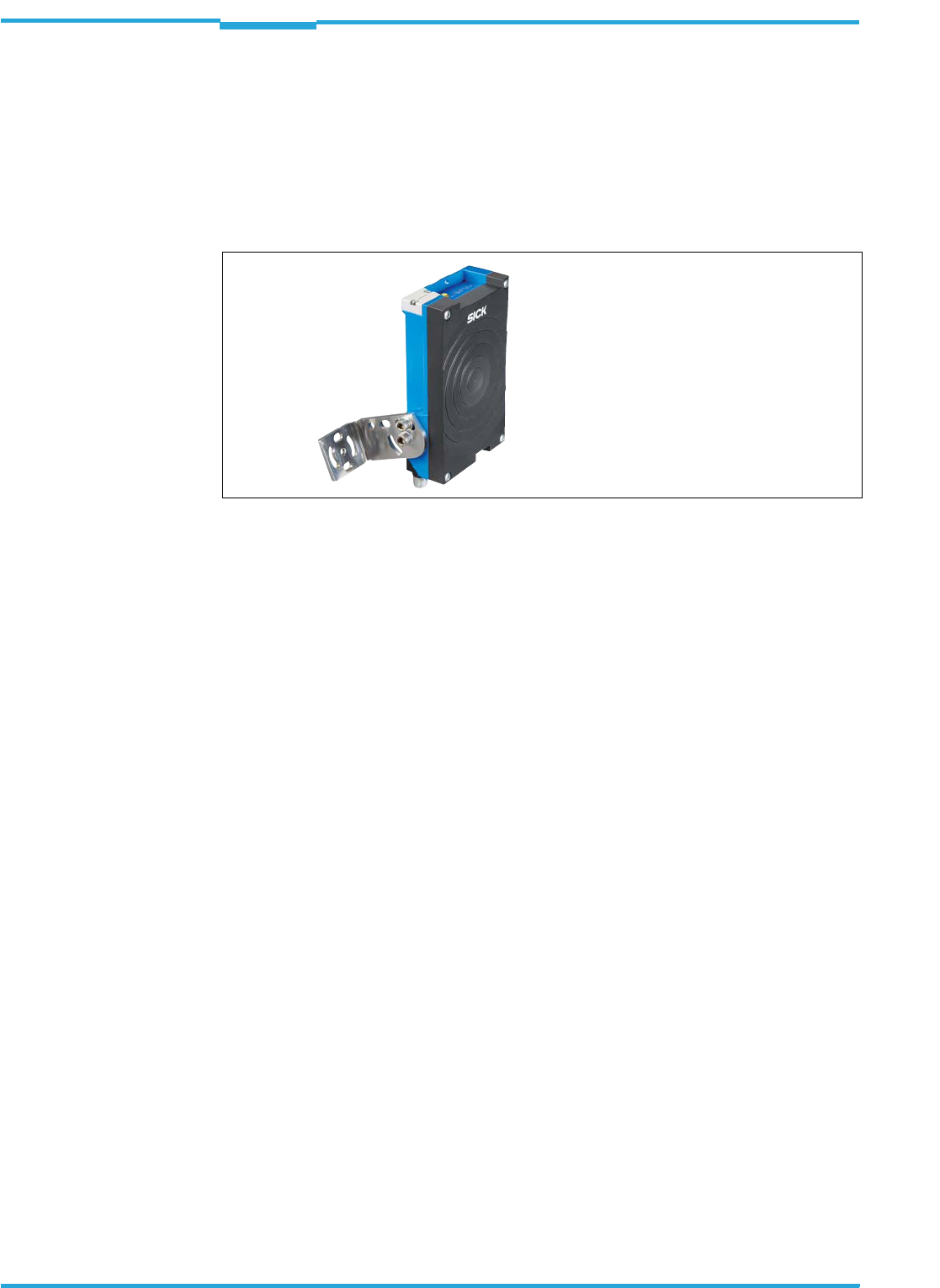
5.2.3 Mounting device
The interrogator is fixed using two blind hole taps (M6), which are located on each narrow
side of the device (see chapter 10.2 Interrogator´s dimensional drawings RFH620.,
page 63) respectively .
The interrogator is mounted using the SICK fastening bracket no. 2048551. The construc-
tion of the angle supports e. g. varied mounting options and the alignment of the interroga-
tor in two axes.
Fig. 5-1: Example: Fixing the interrogator with bracket no. 2048551
Important Always mount the bolts with washers.
When fixing the interrogator with bracket no. 2048551, pay attention to the following di-
mensions:
• Max. thread reach of the blind hole taps: 6.5 mm (0.26 in)
• Plate thickness of the fastening bracket: 4.0 mm (0.16 in)
• Thickness of the washers: 1.6 mm (0.06 in)
• Length of bolt M6x12: 12.0 mm (0.47 in)
The dimensioning of the SICK-holders shows chapter 11.3 Dimensional drawing accesso-
ries, page 66.
Alternatively, the user can provide a holder.
The holder should meet the following requirements:
• Stable mounting device
– Adjustable alignment of the interrogator in the x and y axis
– The mounting device must be able to bear the weight of the interrogator including
its connection cable (depending on the device version) without vibrating.
• Two M6 bolts to fix the interrogator
– The screw length depends on the thickness of the mounting device
– Maximum thread reach in the interrogator 6.5 mm (0.26 in) from the housing sur-
face

Operating Instructions Chapter 5
RFH620 Interrogator
Installation
8013105/0000/2009-05-12 © SICK AG · Division Auto Ident · Germany · All rights reserved 33
5.3 Installation location
The following aspects are relevant for the selection of the installation location:
• Reading distance to the transponder
• Angle alignment of the interrogator
Furthermore, the distance between the interrogator and the host computer and the distan-
ce to the connection module has to be taken into account (see chapter 6.2 Electrical instal-
lation preparations, page 35 and chapter 5.5.1 Installing connection module CDB620 or
CDM420, page 33).
5.4 Installation of the interrogator
1. Prepare base for the installation of the interrogator holder, see chapter 5.2.3 Mounting
device, page 32.
2. Install the interrogator holder on the base.
3. Screw M6 bolts through the holder and into the interrogator's blind hole taps and gently
tighten them.
5.5 Installing external components
5.5.1 Installing connection module CDB620 or CDM420
Depending on the application, you can install either connection module CDB620 or
CDM420. The installation process is the same for both modules.
Important If the PC with the SOPAS-ET configuration software accesses the Interrogator´s auxiliary in-
terface (RS-232; 57.6 kBd) via the connection module, the connection module should not
be installed more than 3 m cable lengths away from the interrogator.
1. Install the connection module close to the interrogator.
2. Install the connection module in such a way that the opened device can be accessed
at any time.
Damage to the device!
The maximum thread reach of the two blind hole taps M6 is 6.5 mm. Longer bolts damage
the device.
>Use bolts of a suitable length.
Important
For detailed information about installation and electrical installation, see the operating ins-
tructions "Connection Module CDB620" (no. 8012119, German/English edition) and "Con-
nection Module CDM420-0001" (no.8010004, German/English edition) respectively.

Chapter 5 Operating Instructions
Radio Frequency RFH620 Interrogator
34 © SICK AG · Division Auto Ident · Germany · All rights reserved 8013105/0000/2009-05-12
Installation
5.5.2 Installing the external reading pulse sensor
If the interrogator is triggered by an external reading pulse sensor (photoelectric reflex
switch), the sensor has to be installed close to the interrogator.
The installation location of the sensor depends on the distance of the transponder to the
front edge of the object. Depending on the application, the sensor should be attached in
such a way that transponders on different sized objects can be fully read during the evalu-
ation (reading gate).
5.6 Dismantling the interrogator
Removal of the components is described in chapter 8.4.1 Dismantling the interrogator,
page 57.
Important
The SICK catalogue "SENSICK Sensors for Automation" (order no. 8006529, German editi-
on) contains a large selection of photoelectric reflex switches and photoelectric proximity
switches as well as accessories (holders, connection cables).

Operating Instructions Chapter 6
RFH620 Interrogator
Electrical installation
8013105/0000/2009-05-12 © SICK AG · Division Auto Ident · Germany · All rights reserved 35
6Electrical installation
6.1 Overview of installation sequence
Important Electrical installation must be performed by qualified staff only.
The following list provides an overview of a typical installation sequence:
• Connecting the interrogator to connection module CDB620 or CDM420
• Wiring the interrogator's data and function interfaces
• Connecting the connection module to the supply voltage
• Connecting a PC for commissioning and configuration (RS-232 or Ethernet)
The actual installation work, which has to be carried out, depends on the respective system
configuration and the version of the interrogator (see chapter 6.2 Electrical installation
preparations, page 35). Once electrical installation has been completed, the interrogator is
started up and configured (see chapter 7 Commissioning and configuration, page 49).
6.2 Electrical installation preparations
The following general requirements should be observed for the electrical installation:
• Supply voltage 10 ... 30 V (functional extra-low voltage in accordance with IEC 60364-
4-41 (VDE 0100 Part 410)), the power supply must provide, at least, 5 W output power
– using connection module CDB620/CDM420: Connection of the supply voltage via
the terminals of the connection module
- or -
using free wiring by customer (without connection module CDB620/CDM420): Con-
nection of supply voltage, e. g., via the cable no. 6034418 (15-pole D-Sub-HD so-
cket on open end)
• With external reading pulsing
– Appropriate reading pulse sensor (start), e. g. photoelectric reflex switch:
for registering an object in the reading area
– Additional appropriate reading pulse sensor (stop), e.g., photoelectric reflex switch:
for registering the end of pulse with extended external reading pulse
• Host computer with data interface RS-232, RS-422/485 or Ethernet: for further proces-
sing the reading data
• Connection cables: refer to the ordering designations of the product information "radio
frequency interrogator RFH620"
Important The possible distance between the interrogator and the host computer depends on the phy-
sical design of the selected host interface and the set data transfer rate.
The following tools are required for the electrical installation:
•Tool
• Digital measuring device (current/voltage measurement)

Chapter 6 Operating Instructions
Radio Frequency RFH620 Interrogator
36 © SICK AG · Division Auto Ident · Germany · All rights reserved 8013105/0000/2009-05-12
Electrical installation
6.3 Electric connections and cables
6.3.1 Electric connections to the interrogator
Important Prerequisites for enclosure rating IP 67:
• The cover of the memory card (optional) has to be installed and screwed together tig-
htly. Width across flats WAF 2.5.
• The connectors are to be firmly screwed to the electric connections of the Ethernet ver-
sion in use.
The same applies to the EMC requirement (ESD) according to CE.
Depending on the device version, the following electric connections are available on the in-
terrogator:
Tab. 6-1: Electric connections to the interrogator with a fixed cable and connector (standard
version)
Tab. 6-2: Electric connections to the interrogator with connector unit (Ethernet version)
Important Additional digital inputs and outputs are available at connection module CDB620/CDM420
(available from week 07/2008) in combination with the parameter memory module
CMC600.
Device version Connection (design) Interfaces for connection to
RFH620-1000001 Cable with connector
(D-Sub-HD, 15-pole, plug)
• RS 232
• RS-422/485
•CAN
• two digital inputs
• two digital outputs
• Power supply
e. g. connection
module CDB620 or
CDM420
Device version Connection (design) Interfaces for connection to
RFH620-1001201 Connector 1 at the connec-
tor unit
(M-12, 4-pole, socket)
• Ethernet Network provided by
the client
Connector 2 at the connec-
tor unit
M-12, 12-pole, plug
• RS 232
• RS-422/485
•CAN
• one digital input
• Power supply
e. g. connection
module CDB620 or
CDM420 or power
supply unit with M-12
socket (no.
2049552), (power
supply only)
Operating Instructions Chapter 6
RFH620 Interrogator
Electrical installation
8013105/0000/2009-05-12 © SICK AG · Division Auto Ident · Germany · All rights reserved 37
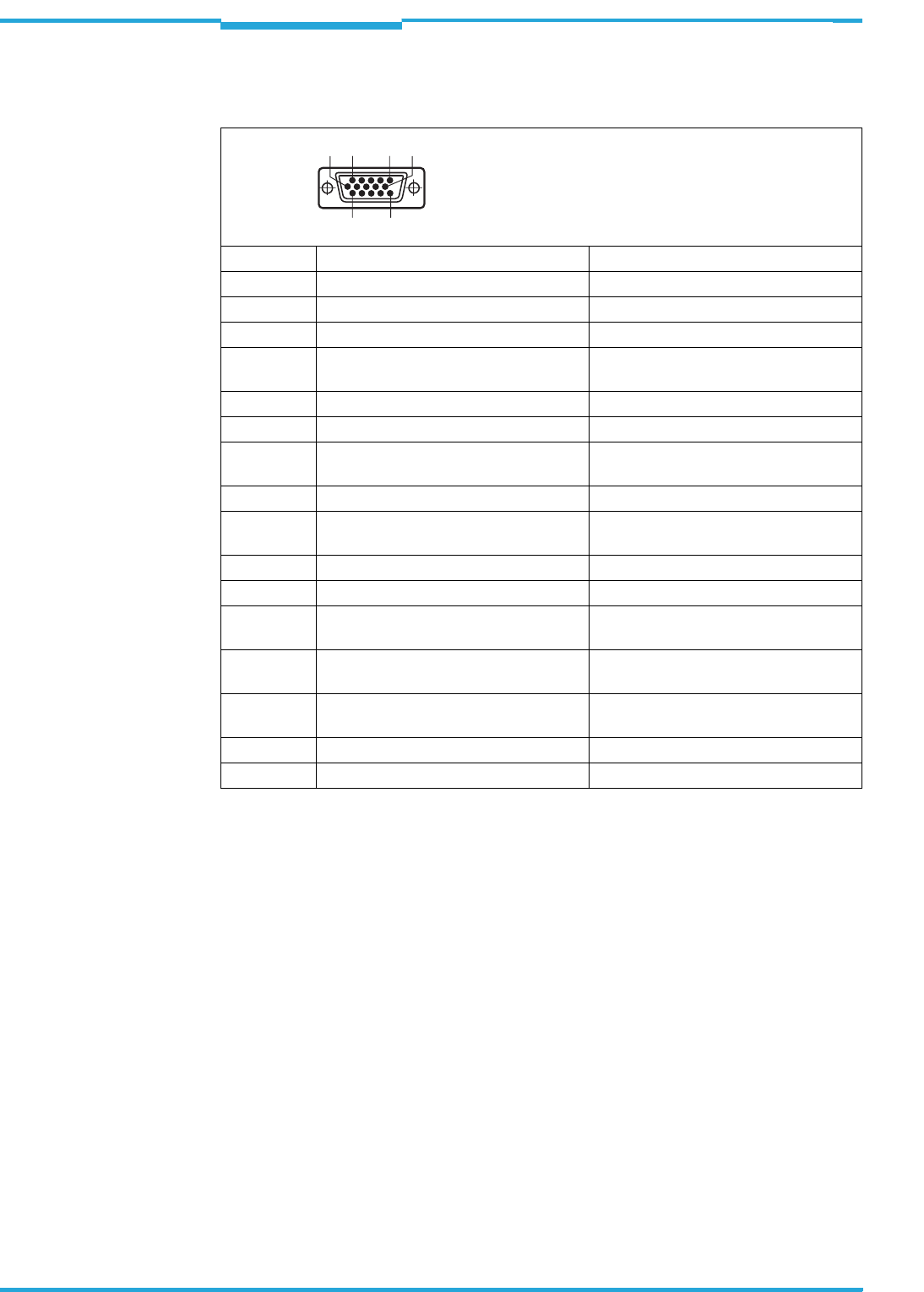
6.3.2 Interrogator´s connections to the cable and connector (standard version)
Tab. 6-3: Standard version: Pin assignment on the 15-pole D-Sub-HD cable connector
Pin Signal Function
1 10 ... 30 V DC Supply voltage
2 RxD (Aux) Aux interface (receiver)
3 TxD (Aux) Aux interface (sender)
4 Sensor 2 Digital switching input (adjustable func-
tion, e. g. external reading pulse)
5GND Ground
6 RD+ (RS-422/485) Host interface (receiver)
7 RD– (RS-422/485);
RxD (RS-232)
Host interface (receiver)
8 TD+ (RS-422/485) Host interface (sender)
9 TD– (RS-422/485);
TxD (RS-232)
Host interface (sender)
10 CAN H CAN bus (IN/OUT)
11 CAN L CAN bus (IN/OUT)
12 Result 1 Digital switching output, adjustable func-
tion
13 Result 2 Digital switching output, adjustable func-
tion
14 Sensor 1 Digital switching input for external rea-
ding pulse
15 SensGND Common ground for the switching inputs
–– Shield
56
11
10
15
1
Chapter 6 Operating Instructions
Radio Frequency RFH620 Interrogator
38 © SICK AG · Division Auto Ident · Germany · All rights reserved 8013105/0000/2009-05-12
Electrical installation
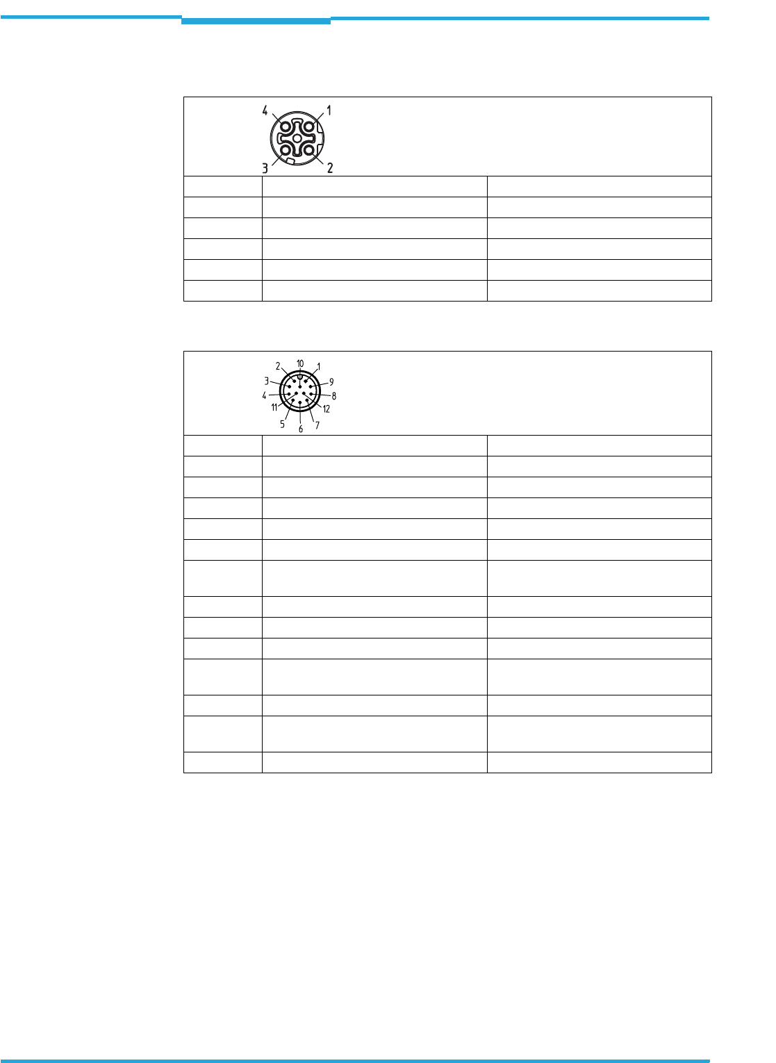
6.3.3 Interrogator´s connections to the connector unit (Ethernet version)
Tab. 6-4: Ethernet version: Pin assignment to the 4-pole M12 socket
Tab. 6-5: Ethernet version: Pin assignment on the 12-pole M12 plug
Important The "sensor 2", "result 1" and "result 2" connections are only available on the interrogator
with a cable and connector (standard version) and for the Ethernet version via the CDB620/
CDM420 connection module in combination with the parameter memory module CMC600.
Pin Signal Function
1TD+ Transmitter+
2RD+ Receiver+
3TD– Transmitter–
4RD– Receiver–
–– Shield
Pin Signal Function
1GND Ground
2 10 ... 30 V DC Supply voltage
3 CAN L CAN bus (IN/OUT)
4 CAN H CAN bus (IN/OUT)
5 TD+ (RS-422/485) Host interface (sender)
6 TD– (RS-422/485);
TxD (RS-232)
Host interface (sender)
7 TxD (Aux) Aux interface (sender)
8 RxD (Aux) Aux interface (receiver)
9 SensGND Switching input sensor 1 ground
10 Sensor 1 Digital switching input (external reading
pulse)
11 RD+ (RS-422/485) Host interface (receiver)
12 RD– (RS-422/485);
RxD (RS-232)
Host interface (receiver)
–– Shield
Operating Instructions Chapter 6
RFH620 Interrogator
Electrical installation
8013105/0000/2009-05-12 © SICK AG · Division Auto Ident · Germany · All rights reserved 39
6.4 Performing electrical installation
Important To ensure secure fastening of the connected connectors and adherence to the enclosure
rating, the knurled nuts/coupling rings of the M12 connectors have to be tightened or the
cable connectors have to be secured.
1. Connect or release current linkages only under de-energised conditions.
2. All wire cross sections and their shields on customer side have to be selected and im-
plemented according to valid engineering standards.
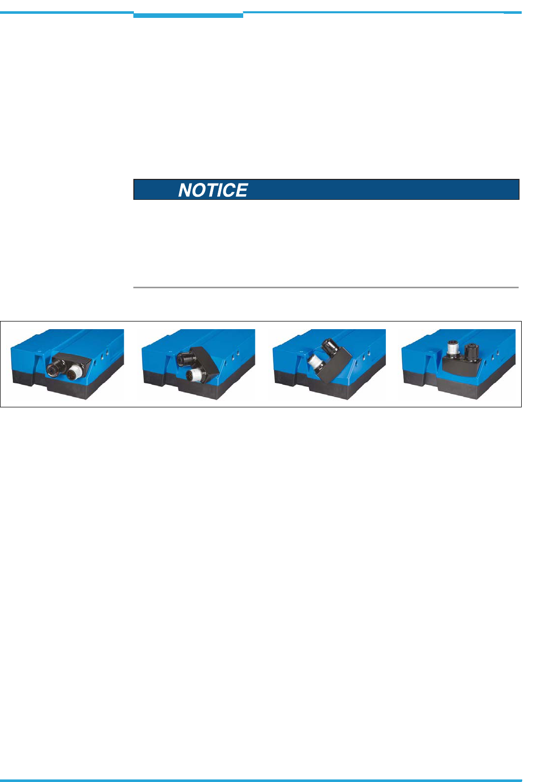
Fig. 6-1: Direction of rotation of the connector unit
6.4.1 Connecting the power supply for the interrogator
For the operation, the interrogator requires a supply voltage of 10 ... 30 V DC (functional ex-
tra-low voltage in accordance with IEC 60364-4-41 (VDE 0100 (part 410)). The functional
extra-low voltage can be created using a safety transformer in accordance with IEC 742
(VDE 0551). The maximum current consumption is 5 W.
Via the connection module CDB620 or CDM420, the interrogator is supplied with
10 ... 30 V DC. If the power supply module CMP400/CMP490 is used, the input voltage is
100 ... 250 V AC/50 ... 60 Hz on the module.
Important The output circuit of the power supply unit must be electrically separated from the input
circuit. This is usually created by means of a safety transformer in accordance with
IEC 742 (VDE 0551).
Damage to the connector unit on the interrogator due to overwinding.
The connector unit on the interrogator has two end positions.
>Never turn the connector unit, of one of the two end positions, more than 180° in one
direction.
>Always rotate the connector unit in the direction of the type plate.
Chapter 6 Operating Instructions
Radio Frequency RFH620 Interrogator
40 © SICK AG · Division Auto Ident · Germany · All rights reserved 8013105/0000/2009-05-12
Electrical installation
Connecting the supply voltage
When wiring the interrogator using connection module CDB620 or CDM420, the interroga-
tor's data and function interfaces are contacted to the connection module together with the
power supply.
1. Ensure that the connection module's supply voltage has been switched off.
2. Standard version: connect the bar code scanner's 15-pole cable plug to the connection
module's 15-pole socket and screw it tight.
- or -
Ethernet version: connect the interrogator's 12-pole plug via a corresponding cable
(e.g., no. 2042916) to the connection module's 15-pole socket and screw it tight.
6.4.2 Wiring serial data interfaces
The maximum data transfer rate of the serial data interface depends on the cable length
and the interface type.
Tab. 6-6: Recommended maximum cable lengths, depending on the selected data transfer rate
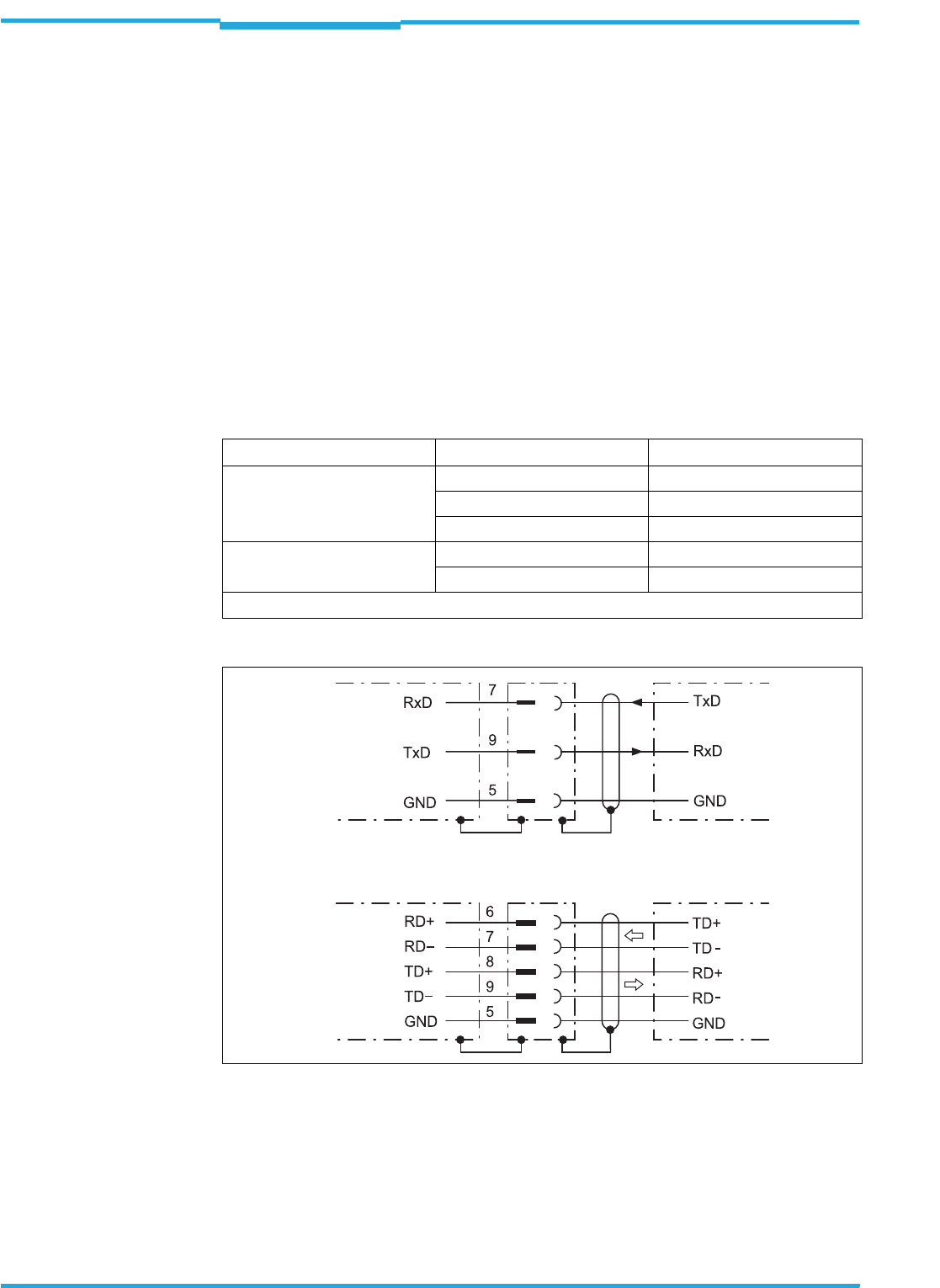
Fig. 6-2: Wiring the serial host data interfaces (RS-232 and RS-422 respectively) on the 15-pole
D-Sub-HD plug
Interface type Transfer rate Distance to the host
RS 232 up to 19,200 Bd Max. 10 m (32.8 ft)
38,400 ... 57,600 Bd Max. 3 m (9.84 ft)
115,200 Bd Max. 2 m (6.56 ft)
RS-422/4851) max. 38,400 Bd max. 1,200 m (3,937 ft)
max. 115,200 Bd max. 500 m (1,640 ft)
1)in corresponding line termination according to the specification
CLV Host
Host
CLV
RS-232
RS-422
Operating Instructions Chapter 6
RFH620 Interrogator
Electrical installation
8013105/0000/2009-05-12 © SICK AG · Division Auto Ident · Germany · All rights reserved 41
Pin assignment for the serial auxiliary data interface on the 15-pole D-Sub-HD plug:
•RxD = Pin 2
• TxD = Pin 3
•GND = Pin 5
1. Connect the interrogator's serial interface to the host using shielded cables in ac-
cordance with the EMC regulations.
Adhere to the maximum cable lengths.
2. To prevent interference, do not lay cables parallel to power supply cables and motor
lines over a longer distance, e. g., in cable channels.
6.4.3 Wiring CAN interface
Damage to the interface module!
Incorrect wiring of the serial data interfaces can damage electronic components in the in-
terrogator.
>Observe information about wiring the serial data interface.
>Check the wiring carefully before switching on the interrogator.
Important
Terminating the RS-422 data interface
Termination can be performed either in connection module CDB620 or CDM420. See ope-
rating instructions "Connection module CDB620" and "Connection module CDM420" re-
spectively.
Important
To wire and configure the interrogator's CAN interface for use in the CAN-SENSOR network,
see the operating instructions "Using the CAN Interface" (no. 8009180, English edition).
Chapter 6 Operating Instructions
Radio Frequency RFH620 Interrogator
42 © SICK AG · Division Auto Ident · Germany · All rights reserved 8013105/0000/2009-05-12
Electrical installation
6.4.4 Wiring the Ethernet interface
Aux and host interface communication can also be executed in parallel via the Ethernet in-
terface.
Fig. 6-3: Function of the Ethernet interface
Important The Ethernet interface of the interrogator has an auto MDIX function. This automatically
sets the speed and any cross connection that is required.
6.4.5 Wiring switching inputs
If the interrogator's reading process should be triggered by an external sensor, the reading
pulse sensor is connected to the "sensor 1" switching input.
Fig. 6-4: Wiring "sensor 1" switching input on the 15-pole D-Sub-HD plug
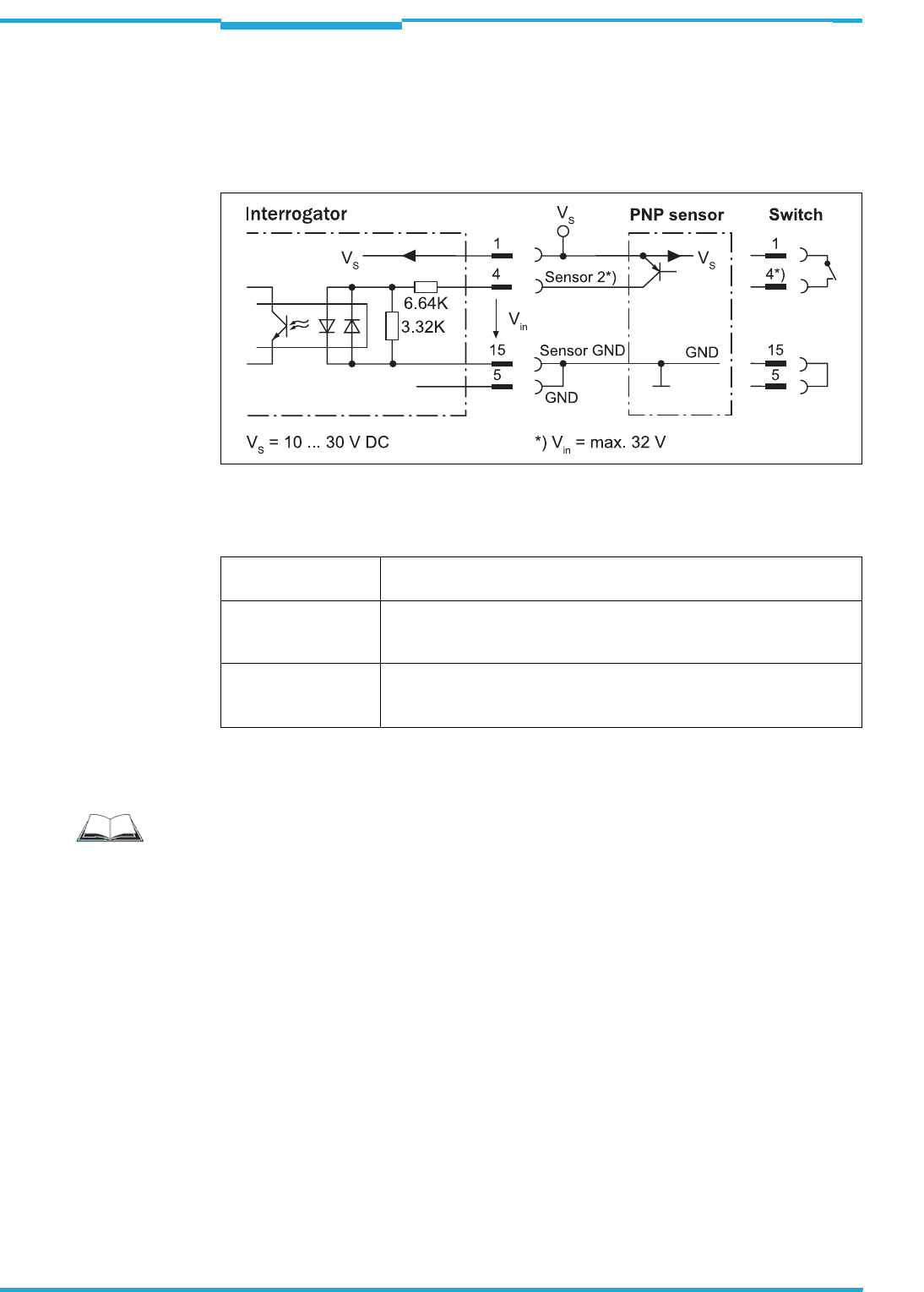
Operating Instructions Chapter 6
RFH620 Interrogator
Electrical installation
8013105/0000/2009-05-12 © SICK AG · Division Auto Ident · Germany · All rights reserved 43
The "sensor 2" switching input has the following functions, among others:
Trigger source for
• Reading pulse generator for reading pulse end
Fig. 6-5: Wiring "sensor 2" switching input on the 15-pole D-Sub-HD plug
Important The ratings for "sensor 1" and "sensor 2" are identical.
Tab. 6-7: Ratings for the switching inputs
>Connect switching inputs depending on application.
Switching behaviour Power fed to the input opens the internal reading gate of the interrogator.
(Default setting: active high, debouncing: max. 30 ms (standard))
Features – Optodecoupled, reverse polarity protected
– Can be wired with the PNP output of a sensor
– Switching input has no hysteresis
Electrical values Low: |Ue| ≤ 2 V; |Ie| ≤ 0.3 mA
High: 6 V ≤ |Ve| ≤ 32 V; 0.7 mA ≤ |Ie| ≤ 5mA
Signal threshold > 3.9 V
Important
To wire the switching inputs using connection module CDB620 or CDM420, see operating
instructions "Connection Module CDB620" (no. 8012119, German/English edition) and
"Connection Module CDM420" (no. 8010004, German/English edition) respectively.
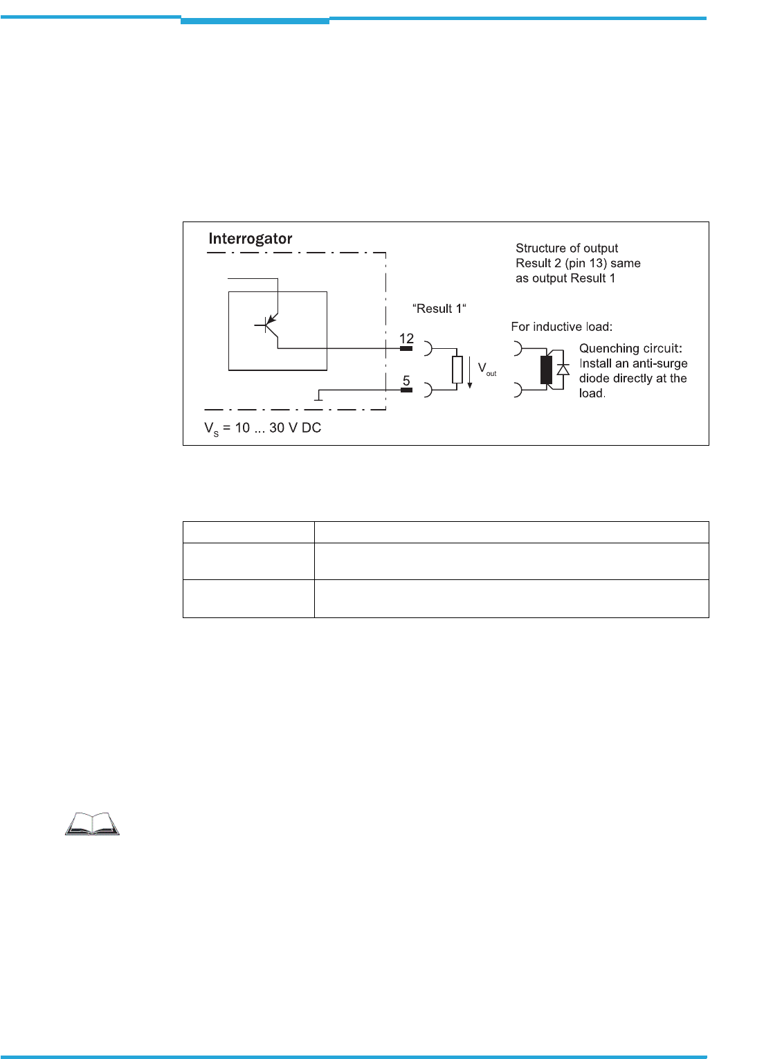
Chapter 6 Operating Instructions
Radio Frequency RFH620 Interrogator
44 © SICK AG · Division Auto Ident · Germany · All rights reserved 8013105/0000/2009-05-12
Electrical installation
6.4.6 Wiring switching outputs
The two switching outputs "result 1" and "result 2" can be allocated various functions for
outputting the result status independent of each other. If the assigned result occurs in the
reading process, the corresponding switching output at the end of the reading pulse is live
for the selected impulse duration.
Important The "result" LED is coupled with none of the two digital switching outputs "result 1" or
"result 2".
Fig. 6-6: Possible wiring of "result 1" switching output on the 15-pole D-Sub-HD plug
Important The ratings of the two switching outputs are identical.
Tab. 6-8: Ratings for the switching outputs
Important Capacitance loads on the switching output affect the switching behaviour. Threshold is a
maximum capacitance of 100 nF. Exceeding this value can lead to unwanted pulsing beha-
viour of the output.
1. Connect switching outputs depending on application.
2. Wire the switching outputs with a load resistance to test the switching functions using
a high-resistance digital voltmeter.
Indication of incorrect voltages/switching statuses is avoided this way.
Switching behaviour PNP switching against the distribution voltage UV
Features Short-circuit proof and temperature-protected,
not galvanically separated from UV
Electrical values 0 V ≤ Ua ≤ UV
Guaranteed: (UV −1.5 V) ≤ Ua ≤ UV in Ia ≤ 100 mA
Important
To wire the switching outputs using connection module CDB620 or CDM420, see the ope-
rating instructions "Connection Module CDB620" (no. 8012119, German/English edition)
and "Connection Module CDM420" (no. 8010004, German/English edition) respectively.
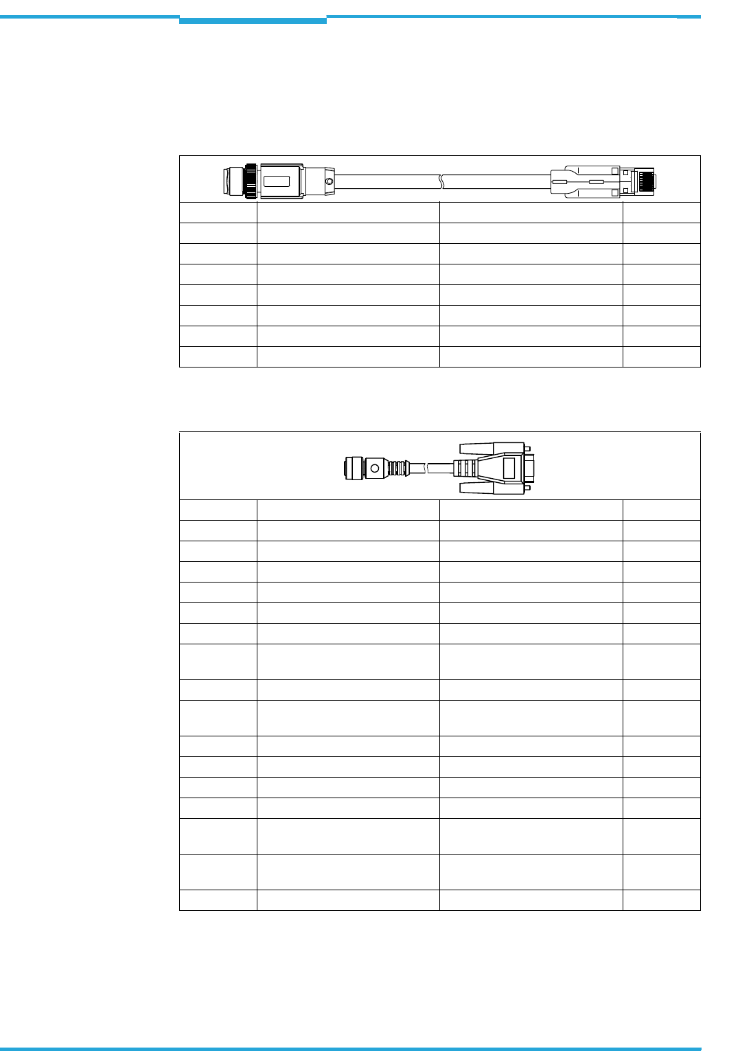
Operating Instructions Chapter 6
RFH620 Interrogator
Electrical installation
8013105/0000/2009-05-12 © SICK AG · Division Auto Ident · Germany · All rights reserved 45
6.5 Pin assignment and wire colours of the assembled cables
6.5.1 Pin assignment of the assembled cables
Cable no. 6034414, 6029630, 6034415, 6030928 (Ethernet version)
Tab. 6-9: Pin assignment on the 4-pole M12 plug and the 6-pole RJ45 plug
Cable no. 2042916, 2041834, 2042914, 2042915 (Ethernet version)
Tab. 6-10: Pin assignment on the 12-pole M12 socket and the 15-pole D-Sub-HD plug
Pin (4-pole) Signal Function Pin (6-pole)
1 TD+ Transmitter+ 1
3 TD– Transmitter– 2
2RD+ Receiver+ 3
––4
––5
4RD– Receiver– 6
–– Shield –
Pin (12-pole) Signal Function Pin (15-pole)
2 10 ... 30 V DC Supply voltage 1
8 RxD (Aux) Aux interface (receiver) 2
7 TxD (Aux) Aux interface (sender) 3
–– – 4
1GND Ground 5
11 RD+ (RS-422/485) Host interface (receiver) 6
12 RD– (RS-422/485);
RxD (RS-232)
Host interface (receiver) 7
5 TD+ (RS-422/485) Host interface (sender) 8
6 TD– (RS-422/485);
TxD (RS-232)
Host interface (sender) 9
4CAN H CAN bus (IN/OUT) 10
3CAN L CAN bus (IN/OUT) 11
–– – 12
–– – 13
10 Sensor 1 Digital switching input for exter-
nal reading pulse
14
9 SensGND Common ground for the switching
inputs
15
–– Shield -
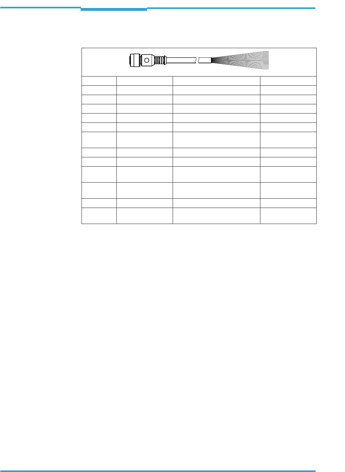
Chapter 6 Operating Instructions
Radio Frequency RFH620 Interrogator
46 © SICK AG · Division Auto Ident · Germany · All rights reserved 8013105/0000/2009-05-12
Electrical installation
6.5.2 Pin assignment and wire colours of the assembled cables with an open end
Cable no. 6034605 (Ethernet version)
Tab. 6-11: Pin assignment on the 12-pole M12 socket and wire colours at the open end
Pin (12-pole) Signal Function Wire colour
1 GND Ground brown
2 10 ... 30 V DC Supply voltage blue
3 CAN L CAN bus (IN/OUT) white
4 CAN H CAN bus (IN/OUT) green
5 TD+ (RS-422/485) Host interface (sender) pink
6 TD– (RS-422/485);
TxD (RS-232)
Host interface (sender) yellow
7 TxD (Aux) Aux interface (sender) black
8 RxD (Aux) Aux interface (receiver) grey
9 SensGND Common ground for the switching
inputs
red
10 Sensor 1 Digital switching input for external
reading pulse
violet
11 RD+ (RS-422/485) Host interface (receiver) grey-pink
12 RD– (RS-422/485);
RxD (RS-232)
Host interface (receiver) red-blue
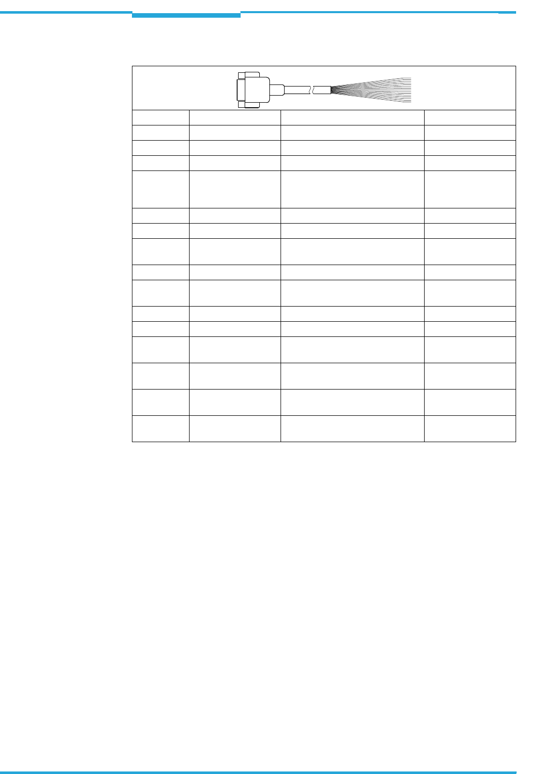
Operating Instructions Chapter 6
RFH620 Interrogator
Electrical installation
8013105/0000/2009-05-12 © SICK AG · Division Auto Ident · Germany · All rights reserved 47
Cable no. 6034418 (Standard version)
Tab. 6-12: Pin assignment on the 15-pole D-Sub-HD socket and wire colours at the open end
Pin (15-pole) Signal Function Wire colour
1 10 ... 30 V DC Supply voltage red
2 RxD (Aux) Aux interface (receiver) violet
3 TxD (Aux) Aux interface (sender) yellow
4 Sensor 2 Digital switching input (adjustable
function, e. g. external reading
pulse)
red-black
5GND Ground black
6 RD+ (RS-422/485) Host interface (receiver) light blue
7 RD– (RS-422/485);
RxD (RS-232)
Host interface (receiver) blue
8 TD+ (RS-422/485) Host interface (sender) light grey-turquoise
9 TD– (RS-422/485);
TxD (RS-232)
Host interface (sender) green
10 CAN H CAN bus (IN/OUT) grey
11 CAN L CAN bus (IN/OUT) pink
12 Result 1 Digital switching output, adjustable
function
brown
13 Result 2 Digital switching output, adjustable
function
orange
14 Sensor 1 Digital switching input for external
reading pulse
white
15 SensGND Common ground for the switching
inputs
white-black

Chapter 6 Operating Instructions
Radio Frequency RFH620 Interrogator
48 © SICK AG · Division Auto Ident · Germany · All rights reserved 8013105/0000/2009-05-12
Electrical installation

Operating Instructions Chapter 7
RFH620 Interrogator
Commissioning and configuration
8013105/0000/2009-05-12 © SICK AG · Division Auto Ident · Germany · All rights reserved 49
7Commissioning and configuration
Commissioning, adjustments as well as configuration and diagnosis are carried out with the
SOPAS-ET configuration software. Among other things, two buttons on the device offer the
possibility to call up a simple reading rate diagnosis (see chapter 4.7.3 Buttons on the in-
terrogator's housing, page 28).
7.1 Overview of the start-up procedure
• Start up the interrogator with the factory default settings
• Install SOPAS-ET configuration software
• Connect the PC with the SOPAS-ET configuration software to the interrogator
• In order to optimise the functionality of the interrogator, adjust and configure the inter-
rogator if necessary
• Check the correct functioning of the interrogator in reading operation
7.2 SOPAS-ET configuration software
The SOPAS-ET configuration software adjusts the interrogator to the reading conditions on
site. The configuration data can be saved and archived as a parameter set (project file) on
the PC.
7.2.1 Functions of the SOPAS-ET configuration software for the interrogator (overview)
The online help in the SOPAS-ET configuration software describes the general functions of
the software and its operation: MENU, HELP, HELP F1
• Selection of the menu language
• Communication set-up with the interrogator
• Password-protected configuration for various operating levels
• Recording of data during the current mode (recording and analysing the data of certain
memory areas of the interrogator with the data recorder)
• Diagnosing the system
7.2.2 System requirements for the SOPAS-ET configuration software
PC system requirements:
• Recommendation: Pentium III, 500 MHz, 512 MB RAM, CD drive, RS-232 serial data
interface or Ethernet interface card, mouse (recommended) and a colour monitor (re-
commended resolution 1,024 x 768 pixels)
• Operating system Windows 2000TM, Windows XPTM or Windows VistaTM
• Free storage space on the hard drive: approx. 300 MB for SOPAS-ET (V. 2.20) configu-
ration software with help files and approx. 70 MB for "Acrobat Reader"
• HTML browser on the PC, e.g., Internet ExplorerTM: For online help system for the SOPAS-
ET configuration software
Connection cables: refer to the ordering designations of the Product information "Interroga-
tor RFH620".
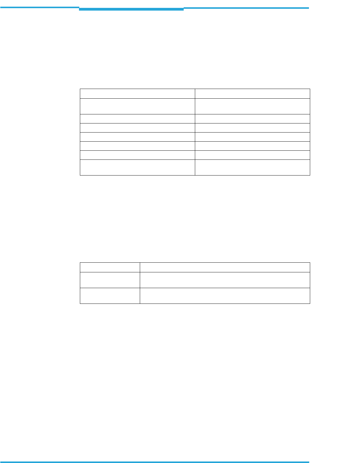
Chapter 7 Operating Instructions
Radio Frequency RFH620 Interrogator
50 © SICK AG · Division Auto Ident · Germany · All rights reserved 8013105/0000/2009-05-12
Commissioning and configuration
7.2.3 Installing the SOPAS-ET configuration software
1. Start the PC and insert the installation CD.
2. If installation does not start automatically, call setup.exe on the CD.
3. Follow the operating instructions to conclude installation.
7.2.4 Default setting for SOPAS-ET configuration software
Tab. 7-1: Default setting for the SOPAS-ET configuration software (excerpt)
7.3 Establishing communication with the interrogator
Prerequisite The TCP-IP protocol on the PC has to be active to enable communication via TCP-IP.
7.3.1 Connecting data interfaces
>Connect the PC and the interrogator via one of the two data interfaces according to the
chart.
Tab. 7-2: Connection between PC with SOPAS-ET configuration software and the interrogator
7.3.2 Starting the SOPAS-ET configuration software and calling the scan assistants
1. Switch on the power supply to the interrogator.
The interrogator performs a self-test and is initialised.
2. Switch on the PC and start the SOPAS-ET configuration software.
As standard, the SOPAS-ET configuration software opens the program window with an
English program interface.
3. In order to change the language setting, click on CANCEL and change the language of the
program interface to GERMAN/DEUTSCH via the menu TOOLS/OPTIONS.
4. Once the language setting has been changed, shut down the SOPAS-ET configuration
software and restart it.
5. In the dialog window, select the option CREATE A NEW PROJECT and click on OK to confirm it.
6. In the main window under SCAN ASSISTANT, click on CONFIGURATION.
The dialog window SCAN ASSISTANT appears.
Parameter Value
User interface language English (the software has to be restarted after
changes)
Units of length Metric
User group (operating level) Maintenance
Download parameter for changes Immediate, temporary (interrogator's RAM)
Upload parameter after online switching Automatic
Window layout 3 (project tree, help, work area)
Serial communication COM 1: 9,600 Bd/19,200 Bd, 8 data bits, 1 stop
bit, no parity 1
via the data interface Comment
ETHERNET (10/100
MBit/s)
Directly connect the PC (Ethernet interface) to the ETHERNET connection
of the interrogator.
RS 232 Connect the PC (serial interface) to the AUX or HOST connection of the
interrogator using a suitable cable.

Operating Instructions Chapter 7
RFH620 Interrogator
Commissioning and configuration
8013105/0000/2009-05-12 © SICK AG · Division Auto Ident · Germany · All rights reserved 51
7.3.3 Configuring the Ethernet connection
TIP To establish a connection quickly and easily via Ethernet, the SOPAS-ET configuration soft-
ware has a CONNECTION WIZARD in the menu TOOLS.
Manual configuration:
1. In the dialog window NETWORK SCAN ASSISTANT under INTERNET PROTOCOL/IP COMMUNICATION,
select the check box for ENABLE IP COMMUNICATION.
2. Click on the button ADD.
3. Enter the IP address of the interrogator in the dialog window and confirm it by pressing
OK.
The dialog window closes. A new entry appears in the list IP ADDRESS CONFIGURATION.
4. Click on OK to confirm settings.
The dialog window ADVANCED SCAN SETTINGS closes.
7.3.4 Configuring the serial connection
1. In the dialog window NETWORK SCAN ASSISTANT under SERIAL PORT/STANDARD PROTOCOL, se-
lect the check box for ENABLE SERIAL COMMUNICATION.
2. Click on ADVANCED....
3. Under SELECT BAUD RATE(S), deactivate all the baud rates except 57.6 KBD.
4. Select the following PORT SETTINGS: 8 data bits, no parity, 1 stop bit.
5. Click on OK to confirm settings.
The dialog window ADVANCED SCAN SETTINGS closes.
7.3.5 Carrying out a scan
1. In the dialog window SCAN ASSISTANT, click on START SCAN.
2. Select the listed devices (RFH620) and confirm with ADD DEVICE.
Connected devices are searched for via the connection. The SOPAS-ET configuration
software inserts the devices found in the project tree and uploads the current parame-
ter set (SYNC CHECK).
3. For the configuration of the devices, see chapter 7.4.2 Configuring the interrogator,
page 53.
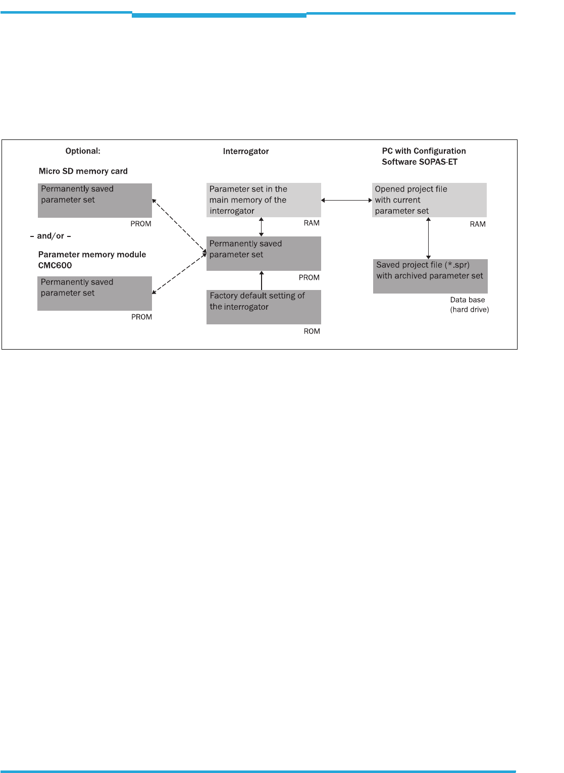
Chapter 7 Operating Instructions
Radio Frequency RFH620 Interrogator
52 © SICK AG · Division Auto Ident · Germany · All rights reserved 8013105/0000/2009-05-12
Commissioning and configuration
7.4 Initial commissioning
The SOPAS-ET configuration software adjusts the interrogator to the reading conditions on
site. Starting point for this is the factory default setting which can be adjusted to optimise
the interrogator. The SOPAS-ET configuration software is used to create an application-spe-
cific parameter set, which can be loaded permanently into the interrogator and saved/ar-
chived on the PC as a project file (spr file with configuration data).
Fig. 7-1: Configuration with SOPAS-ET and storage of the parameter set
If the interrogator is optionally connected to a Micro SD memory card (see chapter 4.7.4 Pa-
rameter set on the Micro SD memory card (optional), page 29) or connected to a module
with parameter memory mode CMC600, the parameter set is saved permanently to the me-
mory card, or to the CMC600 respectively, with every permanent storage of the parameter
set in the interrogator.
After the interrogator is restarted, it automatically transfers the parameter set from the me-
mory card and the CMC600 to its permanent memory respectively. Thus, an interrogator
can, e. g., be exchanged without losing configuration data (see chapter 8.4.2 Replacing the
interrogator, page 58). If a memory card and a CMC600 are available, the interrogator will
load the parameter set from the CMC600.
7.4.1 Overview of the start-up procedure
• Connect data interfaces of the PC and the interrogator
• Start the SOPAS-ET configuration software and create a new project file
• Configure the scan assistant (activate PC communication)
• Establishing communication with the interrogator
• Accept current configuration of the interrogator in the project tree
• Log on to the interrogator as an "authorised client"
• Configure the interrogator for use
• Load the optimised configuration into the interrogator and save permanently
• Save the project file with the configuration data of the interrogator on the PC

Operating Instructions Chapter 7
RFH620 Interrogator
Commissioning and configuration
8013105/0000/2009-05-12 © SICK AG · Division Auto Ident · Germany · All rights reserved 53
7.4.2 Configuring the interrogator
All configurable parameters for the interrogator are grouped into a device description (jar
file) for the SOPAS-ET configuration software. The device description's project tree acts as
a guideline for the configuration.
The function of each respective parameter is explained in a context-sensitive manner in an
online help (F1 key). The valid value range and the default setting list the display window
PARAMETER INFO (right mouse button, when the cursor is positioned over the parameter).
1. In the menu bar under TOOLS, select the command LOGIN TO DEVICE.
2. In the dialog window under USERLEVEL in the list box, select the entry AUTHORIZED CLIENT.
If the parameter set is password-protected, enter the password "client" in PASSWORD.
The password protection is activated/deactivated on the register tab PARAMETER.
3. Click on OK to confirm the dialog window.
The previously greyed out parameters on the register tabs are now accessible.
7.4.3 Permanently load changed parameter sets into the device
Changed parameter values are immediately transferred to the interrogator's main memory
(RAM) depending on the option ("Immediate download"). To ensure that the changes remain
even after the interrogator is restarted, the configuration has to be permanently saved in
the interrogator's PROM.
>In order to load the current settings permanently in the interrogator, in the menu bar
under RFH620, select the command PARAMETER/SAVE PERMANENT or click on in the
tool bar.
Note
In order to configure a device via the SOPAS-ET configuration software, the respective ope-
rating level has to be selected in advance. After the start, the SOPAS-ET configuration soft-
ware functions at the operating level "MAINTENANCE".

Chapter 7 Operating Instructions
Radio Frequency RFH620 Interrogator
54 © SICK AG · Division Auto Ident · Germany · All rights reserved 8013105/0000/2009-05-12
Commissioning and configuration
7.4.4 Save, display and print the current parameter set
When archiving a parameter set, it is recommended to not only save the project file on the
PC but also to print out the contents of the file.
1. In order to save the current parameter set, select the menu item SAVE AS in the menu
bar under PROJECT.
2. Enter a file name in the dialog window and confirm it by clicking on SAVE.
The SOPAS-ET configuration software saves the current settings in a configuration file
"*.spr".
3. In order to print out the current parameter set, select the command PRINT/PRINT PREVIEW
in the menu bar under PROJECT.
The SOPAS-ET configuration software displays a preview of a table with a list of all the
parameter values.
4. Click on in the tool bar at the top of the dialog window.
The dialog window PRINT for the printer configuration appears.
5. Edit setting accordingly and confirm with OK.
The current project settings are printed as a table on several pages.
TIP To save the current parameter set as a PDF, in the menu bar under PROJECT select the com-
mand PRINT/SAVE AS PDF FILE.

Operating Instructions Chapter 7
RFH620 Interrogator
Commissioning and configuration
8013105/0000/2009-05-12 © SICK AG · Division Auto Ident · Germany · All rights reserved 55
7.5 Default setting
The values of the default setting are permanently saved in the interrogator (ROM) and in the
database of the SOPAS-ET configuration software in the device-specific jar file (see
chapter 7.4 Initial commissioning, page 52). A PC is not required to start up the interrogator
with the default setting.
7.5.1 Resetting the default setting in the interrogator
Prerequisite The SOPAS-ET configuration software is connected online to the interrogator.
Two default setting types can be called up via the SOPAS-ET configuration software:
• Complete default setting (LOAD DEFAULT SETTING)
SOPAS-ET resets all parameter values of the interrogator to default. Settings, which
have been previously made for the communication parameters of the Ethernet inter-
faces or serial data interfaces (e.g. Ethernet address), are overwritten. In the process,
the connection(s) to the interrogator disappear(s) as the case may be and must to be
reconfigured.
• Application-specific default setting (LOAD APPLICATION DEFAULT SETTING)
SOPAS-ET resets the parameter values of the interrogator, but does not change the
communication parameters. Settings, which have been previously made for the com-
munication parameters of the Ethernet interfaces or serial data interfaces, are kept
and the current connection(s) to the interrogator remain(s) established.
1. In order to discard changes to the parameter set as described above, select the cor-
responding command in the menu bar under RFH620.
The SOPAS-ET configuration software loads the default setting from the interrogator
and displays the parameter values in the register tabs. In the interrogator, the default
setting will first be active in the temporary main memory only.
The default setting can also be saved in the PC or printed (see chapter 7.4.4 Save, dis-
play and print the current parameter set, page 54).
2. In the menu bar under TOOLS, select the command LOGIN TO DEVICE.
3. In the dialog window under USERLEVEL in the list box, select the entry AUTHORISED CLIENT.
If the parameter set is password-protected, enter the password "client" in PASSWORD.
4. Click on OK to confirm the dialog window.
5. In the menu bar under RFH620, select the command PARAMETER/SAVE PERMANENT.
The SOPAS-ET configuration software transfers the default setting to the permanent pa-
rameter memory (PROM) of the interrogator.
If the interrogator is equipped with the Micro SD memory card or connected to a con-
nection module CDB620/CDM420 with parameter memory module CMC600, the de-
fault setting will be permanently transferred to the parameter memory CMC600 and
memory card respectively.
Important Once the default setting has been restored, password-protection is deactivated.

Chapter 7 Operating Instructions
Radio Frequency RFH620 Interrogator
56 © SICK AG · Division Auto Ident · Germany · All rights reserved 8013105/0000/2009-05-12
Commissioning and configuration

Operating Instructions Chapter 8
RFH620 Interrogator
Maintenance
8013105/0000/2009-05-12 © SICK AG · Division Auto Ident · Germany · All rights reserved 57
8Maintenance
8.1 Maintenance during operation
It RFH620 operates maintenance-free in all variants.
Important Do not open the interrogator's housing. If the device is opened, the SICK AG warranty shall
not apply.
8.2 Cleaning the housing
>Use a soft cloth to free the housing of dust.
>If necessary, also clean the LEDs on the housing.
8.3 Checking the incremental encoder
If an optional incremental encoder is used, the position of the friction wheel at the drive sys-
tem should be checked at regular intervals.
>Ensure that the incremental encoder has direct and fixed contact with the drive system
and that the friction wheel rotates without slipping.
8.4 Replacing an interrogator
Incorrect or damaged devices have to be removed and replaced with either new or repaired
devices.
Important Repairs to the interrogator should only be carried out by qualified and authorised SICK AG
service staff.
8.4.1 Dismantling the interrogator
1. Switch off the power supply to the interrogator.
2. Disconnect all the connection cables of the interrogator.
3. Remove the interrogator from the holder. In the process, mark the interrogator´s situ-
ation and alignment on the holder or environment.
4. If available, remove the Micro SD memory card (optional) with the stored parameter set
from the faulty interrogator (see chapter 4.7.4 Parameter set on the Micro SD memory
card (optional), page 29). To do this, open the cover and slightly press on the memory
card in order to unlock it.
5. Insert the memory card accordingly into the empty space of the new, turned-off interro-
gator the right way round (the card's notches point to the two yellow keys) until it is lo-
cked.
6. Close the cover again.

Chapter 8 Operating Instructions
Radio Frequency RFH620 Interrogator
58 © SICK AG · Division Auto Ident · Germany · All rights reserved 8013105/0000/2009-05-12
Maintenance
8.4.2 Replacing the interrogator
1. Align and install the new or repaired interrogator (see chapter 5 Installation, page 31).
In the process, observe any marks made previously on the holder or the environment
(chapter 8.4.1 Dismantling the interrogator, page 57).
2. Re-connect connection cables to the interrogator (see chapter 6 Electrical installation,
page 35).
3. Switch the power supply to the interrogator back on.
The interrogator starts with the default setting.
4. If, as an option, a Micro SD memory card has been inserted into the interrogator or a
parameter memory module CMC600 into connection module CDB620/CDM420, the
new interrogator will automatically load the stored parameter set from the memory card
or CMC600 into its permanent memory. If both a memory card and a CMC600 are
available, the interrogator will load the parameter set from the CMC600.
- or -
Without Micro SD memory card /parameter memory module CMC600: Connect to the
interrogator via the SOPAS-ET configuration software, transfer the configuration stored
on the PC via download to the interrogator and permanently store the configuration the-
re.

Operating Instructions Chapter 9
RFH620 Interrogator
T
roubleshooting
8013105/0000/2009-05-12 © SICK AG · Division Auto Ident · Germany · All rights reserved 59
9Troubleshooting
This chapter describes how errors in the interrogator can be recognised and eliminated.
9.1 Overview of errors and malfunctions which could occur
9.1.1 Error during the installation
• The interrogator has been unsuitably aligned to objects with transponders (e. g. a
shield)
• Reading pulse sensor has been positioned incorrectly (e.g. internal reading gate is
opened too late or shut too early)
9.1.2 Error during the electrical installation
• Interfaces of the interrogator were wired incorrectly
9.1.3 Error during configuration
• Functions have not been adjusted to the local conditions, e.g. parameters for the data
interface are set incorrectly
• Device-related limits have not been considered, e.g. reading distance
• Trigger source for reading pulse selected incorrectly
9.1.4 Malfunctions during operation
• Start/Stop operation: External reading pulse is missing, more than one object is in the
reading area
• Device error (hardware/software)
9.2 Detailed malfunction analysis
9.2.1 LEDs on the interrogator
Among other things, the following statuses can be read from the LEDs on the interrogator's
housing (see chapter 4.7.2 LEDs on the interrogator's housing, page 27):
• Ready
• Status of the reading result (result)
• Data traffic on the host, aux and CAN interface
The LEDs can display possible malfunctions or errors. Please refer to the system informati-
on for further details.
9.2.2 System information
The interrogator displays errors in various ways. The error output is hierarchised and always
allows a detailed analysis:
• Communication errors can occur while transferring telegrams to the interrogator. In this
case, the interrogator returns an error code.
• Error codes are written into a status protocol for errors which occur during a reading
(see subsequent chapter).

Chapter 9 Operating Instructions
Radio Frequency RFH620 Interrogator
60 © SICK AG · Division Auto Ident · Germany · All rights reserved 8013105/0000/2009-05-12
Troubleshooting
9.3 Status protocol
Important The status protocol remains even after switching the interrogator off and on again.
The interrogator differentiates between four types of error:
• Information
•Warning
•Error
• Fatal error
The interrogator only saves the last five entries for each of the error types.
9.3.1 Displaying the status protocol using the SOPAS-ET configuration software
In order to display the status protocol, the SOPAS-ET configuration software has to be online
and connected to the interrogator.
1. Connect the SOPAS-ET configuration software with the device.
2. Open the project tree RFH620, SERVICE, SYSTEM STATUS, register tab SYSTEM INFORMATION.
9.4 SICK support
If an error cannot be eliminated, it is possible that the interrogator is defective. The interro-
gator cannot be repaired by the user, meaning that it is not possible to re-establish func-
tions after a failure. However, the interrogator can be rapidly replaced by the user (see
chapter 8.4 Replacing an interrogator, page 57 for this).
>If an error occurs which cannot be eliminated, please contact SICK service:
• In Germany: Technical hotline of SICK Vertriebs-GmbH
– Tel. +49 211 5301-270
– Fax. +49 211 5301-100
– E-mail: info@sick.de
• International: your appropriate SICK branch office and SICK subsidiary respectively.
– For telephone numbers and e-mail addresses, please see the back page of these
operating instructions
– For the postal address please visit www.sick.com.
>Only return devices after consultation with the SICK service.
Important Repairs to the interrogator should only be carried out by qualified and authorised SICK AG
service staff.

Operating Instructions Chapter 10
RFH620 Interrogator
Technical data
8013105/0000/2009-05-12 © SICK AG · Division Auto Ident · Germany · All rights reserved 61
10 Technical data
10.1 Interrogator´s data sheet RFH620.
Type RFH620-1000001 RFH620-1001201
Wave band
(Carrier frequency)
13.56 MHz (13.553 ... 13.567 MHz)
HF transmitter power 200 mW
Transponder type ISO/IEC 15693 (18000-3M1)
MTTF 20,000 h
Cruising range Up to 16 cm (depending on the size of the transponder)
Useable antenna surface area 125 x 75 mm2 (4.92 x 2.95 in2)
Optical indicators 6 LEDs: Ready, result, HF, data, CAN, LNK TX
Acoustic display Beeper, which can be switched off, with function for result status display is available
Reading pulsing • Pulse sources for start: Switching inputs
"sensor 1" and/or "sensor 2"; command; auto-
matic cycle; CAN
• Pulse sources for stop: Reading pulse source,
"sensor 1", "sensor 2", command, timer, good
read, condition
• Freewheel
• Pulse sources for start: Switching inputs
"sensor 1"; command; automatic cycle; CAN
• Pulse sources for stop: Reading pulse source,
"sensor 1", command, timer, good read, condi-
tion
• Freewheel
"Host" data interface Serial: RS-232 or RS-422/485; Ethernet (port 2112),
adjustable data format (serial) and data output format
Data transfer rate 0.3 ... 500 kBd
Protocols SICK standard (SOPAS-Cola-A)
Physical configurations Stand-alone
"Aux" data interface Serial: RS-232 (57.6 kBd; 8 data bits, no parity, 1 stop bit); Ethernet (port 2111); fixed data output
format
"Ethernet" data interface Only for Ethernet version: 10/100 MBit/s, TCP/IP, half/full duplex
Data interface "CAN"*20 kBit/s ... 1 MBit/s, SICK CAN-SENSOR network (master, slave, multiplexer)
Digital switching inputs 2 ("sensor 1", "sensor 2"), 2 additional inputs via
CMC600 in CDB620
1 ("sensor 1"), 2 additional inputs via CMC600 in
CDB620, optodecoupled, Ue = max. 32 V, reverse
polarity protected, which can be wired with PNP
output, configurable debouncing 0 ... 10,000 ms
Digital switching outputs 2 ("result 1", "result 2"), 2 additional outputs via
CMC600 in CDB620
PNP, Ia = max. 100 mA, short circuit-proof, confi-
gurable impulse duration (static, 10 ... 1,000
ms)
No output, 2 outputs via CMC600 in CDB620
Electric connection Cable (0.9 m (2.95 ft)) with 15-pole D-Sub-HD
plug
Revolving connector unit with 2 M12 circular
connectors
(12-pole plug, 4-pole socket)
Operating voltage/
Power consumption
10 ... 30 V DC (PELV according to EN 61140 (2002-03)) / max. 5 W
Housing Die-cast aluminium
Antenna cover material PPS Plastic
Electrical safety According to EN 60950-1 (2006-04)
Enclosure rating III, according to EN 61140 (2002-03)
Enclosure rating IP 67, according to EN 60529 (1991-10); A1 (2002-02)
EMV tested According to EN 301489

Chapter 10 Operating Instructions
Radio Frequency RFH620 Interrogator
62 © SICK AG · Division Auto Ident · Germany · All rights reserved 8013105/0000/2009-05-12
Technical data
Tab. 10-1: Technical specifications of the interrogator RFH620
Wireless authorisation According to EN 300330 (2006-04) FCC version: according to FCC part 15
Vibration/shock test According to EN 60068-2-6 (1995) / according to EN 60068-2-27 (1993)
Weight 520 g (18.34 oz) with connecting cable 450 g (15.87 oz) without connecting cables
Ambient operating/
storage temperature
–25 ... +60 °C (-13 ... 140 °F)/–25 ... +70 °C (-13 ... 158 °F)
Max. rel. humidity 90 %, non condensing
Housing colour Light blue (according to RAL 5012)
* in priming
Type RFH620-1000001 RFH620-1001201
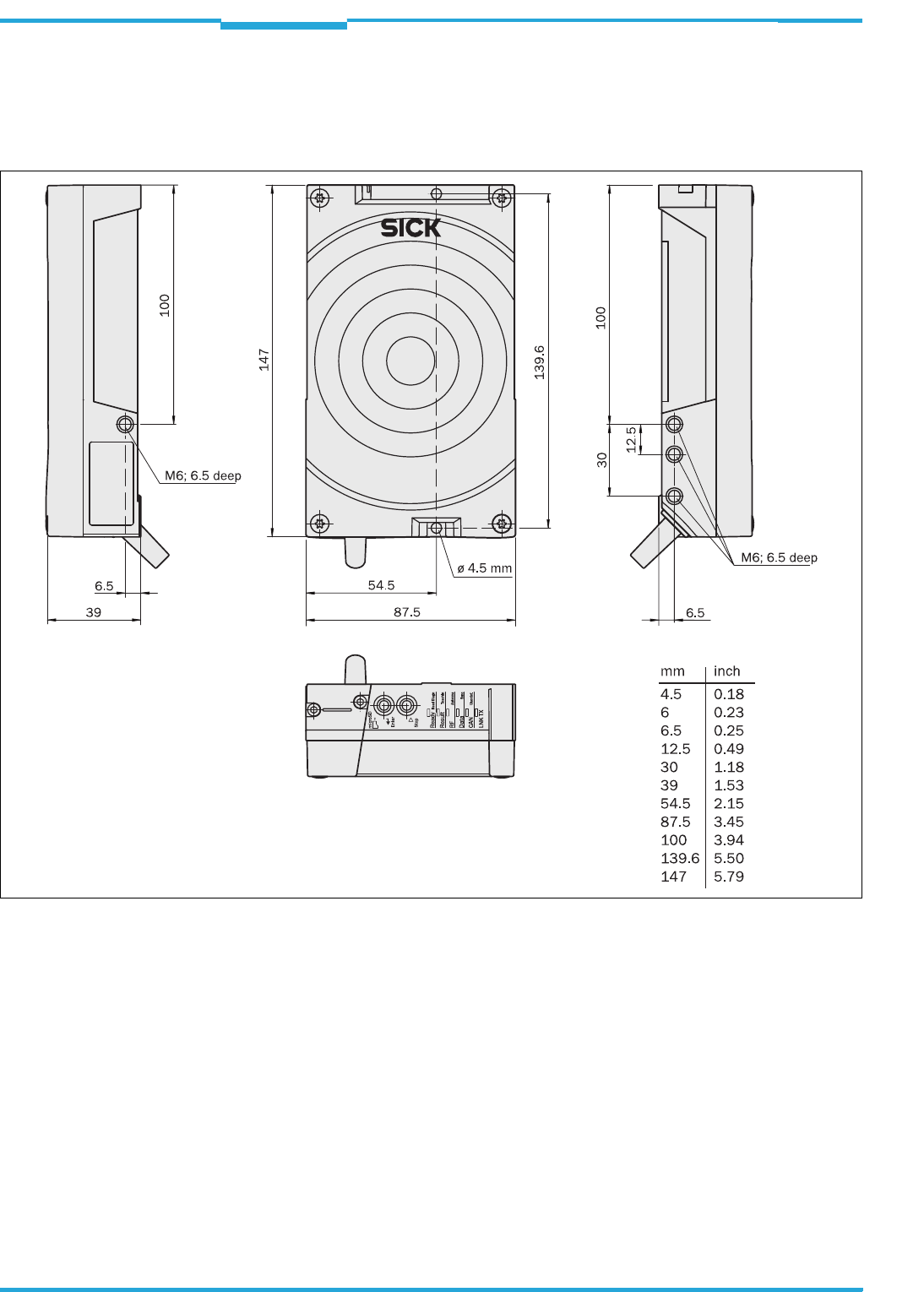
Operating Instructions Chapter 10
RFH620 Interrogator
Technical data
8013105/0000/2009-05-12 © SICK AG · Division Auto Ident · Germany · All rights reserved 63
10.2 Interrogator´s dimensional drawings RFH620.
10.2.1 Dimensional drawing of interrogator RFH620-1000001
Fig. 10-1: Standard version: Dimensions of the interrogator (RFH620-1000001)
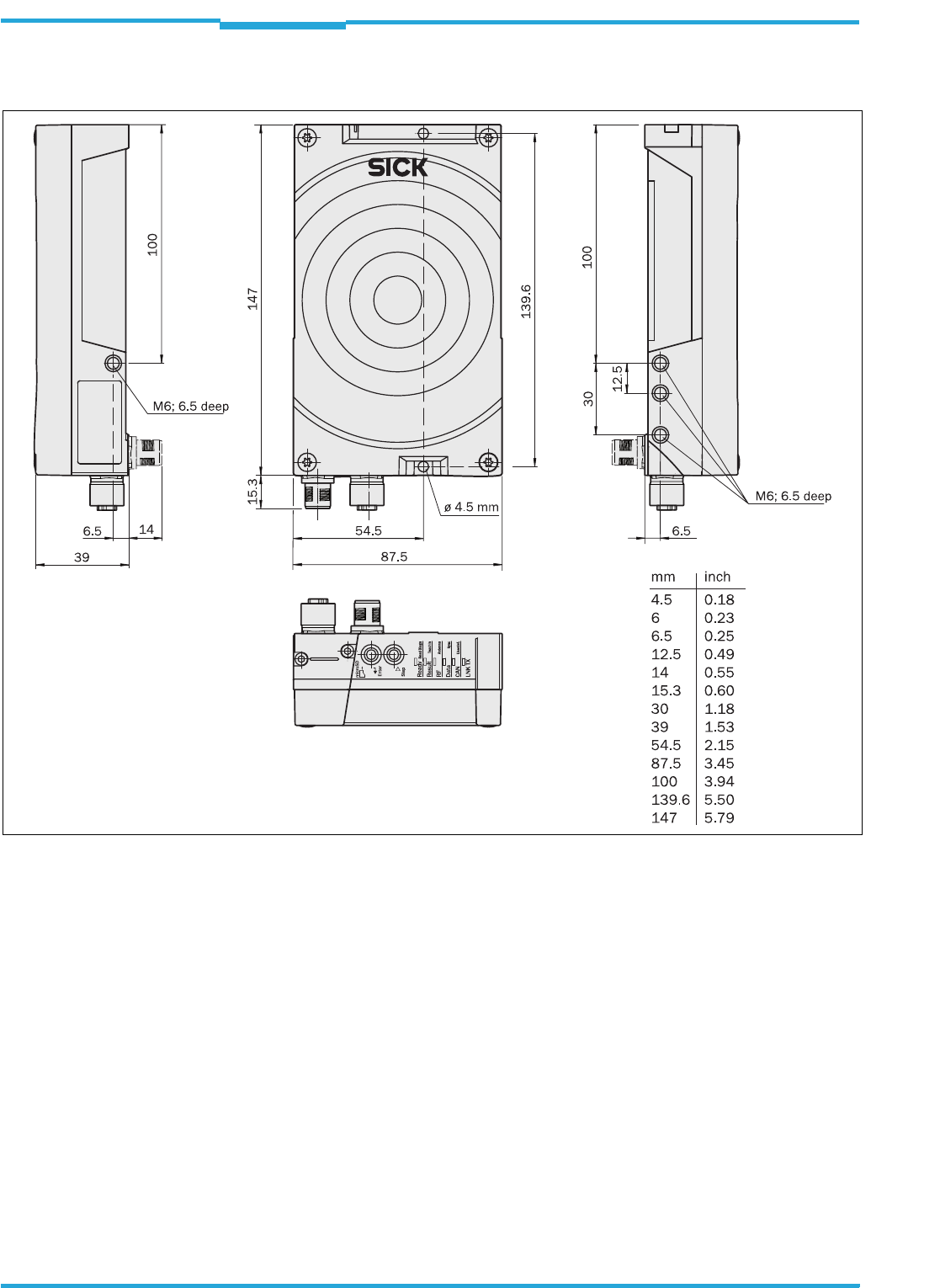
Chapter 10 Operating Instructions
Radio Frequency RFH620 Interrogator
64 © SICK AG · Division Auto Ident · Germany · All rights reserved 8013105/0000/2009-05-12
Technical data
10.2.2 Dimensional drawing of interrogator RFH620-1001201
Fig. 10-2: Ethernet version: Dimensions of the interrogator (RFH620-1001201)

Operating Instructions Chapter 11
RFH620 Interrogator
Appendix
8013105/0000/2009-05-12 © SICK AG · Division Auto Ident · Germany · All rights reserved 65
11 Appendix
11.1 Overview of the Appendixes
The appendix contains the following additional information:
• Configuration with command strings
• Dimensional drawings of the accessories
• Supplementary documentation (overview)
• Copy of EC Declaration of Conformity
11.2 Configuring the interrogator with command strings
As an alternative to the SOPAS-ET configuration software, the interrogator can also be con-
figured and operated with command strings via all the data interfaces. The command
strings can be displayed separately via the SOPAS-ET configuration software.
Important Both the command strings and the SOPAS-ET configuration software are based on com-
mand language which directly accesses the command interpreter of the interrogator. This
command language must be used with care as the interrogator executes sent commands
immediately. Parameter values altered via commands are, at first, only active in the current
parameter set in the working memory (RAM) of the interrogator. To save in the permanent
memory, the altered parameter set must be copied into the PROM using a special com-
mand; this ensures that the alterations are not lost when the power supply is switched off.
Command strings for triggering the reading pulse:
• START: <STX>sMN mTCgateon<ETX>
• STOP: <STX>sMN mTCgateoff<ETX>
If the commands are entered via the terminal emulator of the SOPAS-ET configuration soft-
ware, the two control characters <STX> and <ETX> are omitted.
Connection to the interrogator using the terminal emulator via the Ethernet:
1. Call up the terminal emulator via the menu TOOLS/TERMINAL of the SOPAS-ET configura-
tion software and, in the terminal emulator, call up the connection assistant via the
menu SET UP CONNECTIONS/CONNECTION.
2. Select the option USER-DEFINED CONNECTION in the connection assistant and confirm by
pressing NEXT.
3. Select the option TCP/IP and confirm by pressing NEXT.
4. Select the option SHOW ONLY COLA TELEGRAMS.
5. Enter the interrogator's IP address in the relevant field and confirm by pressing NEXT.
6. In the selection list ADDRESSING MODE, select the setting NAME and confirm by pressing
CONNECT.
The connection with the interrogator is established. The command strings can be trans-
ferred.
Note
For this purpose, select the setting COMMAND on the register tab OBJECT TRIGGER CONTROL as
Trigger source.
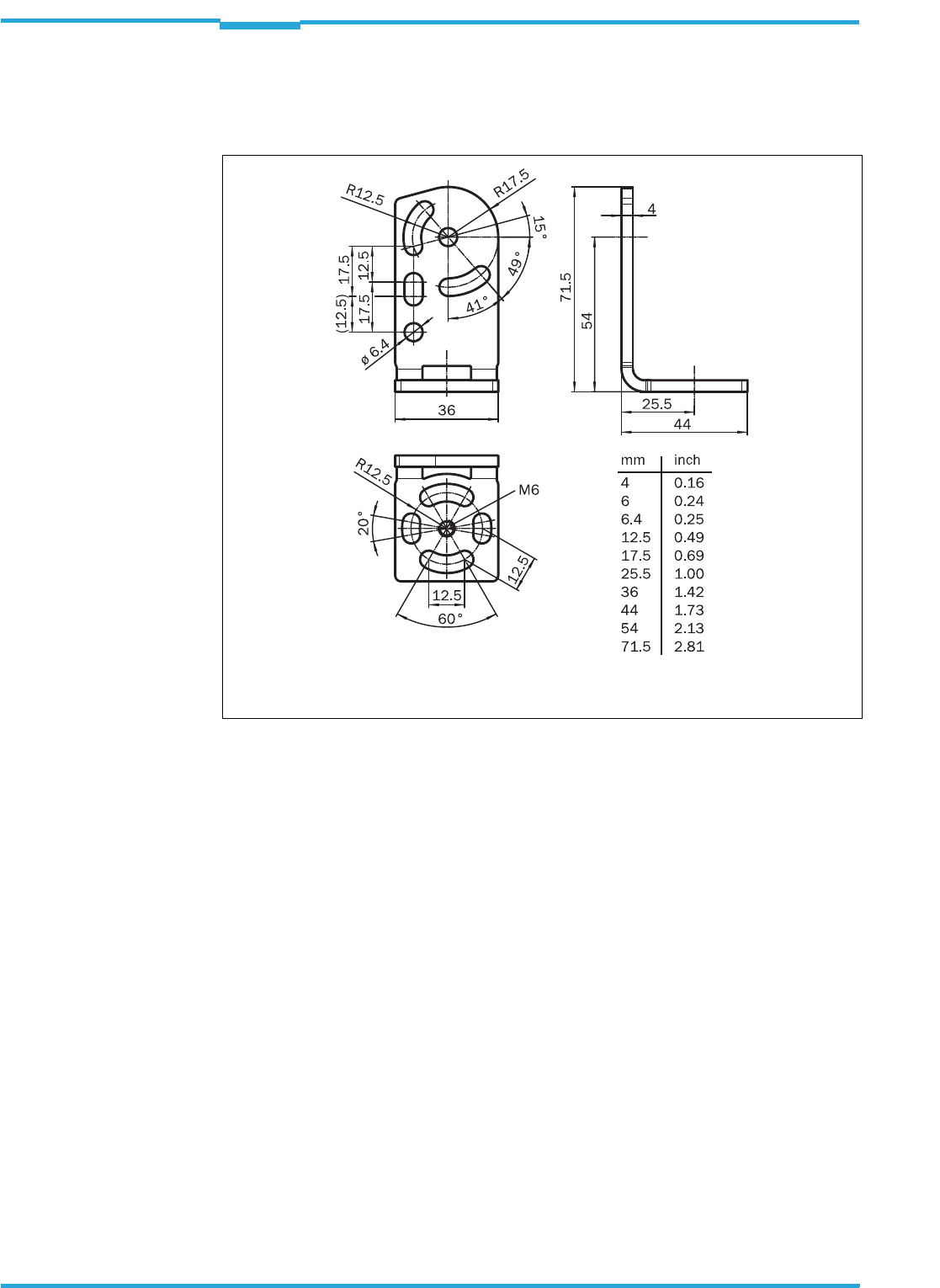
Chapter 11 Operating Instructions
Radio Frequency RFH620 Interrogator
66 © SICK AG · Division Auto Ident · Germany · All rights reserved 8013105/0000/2009-05-12
Appendix
11.3 Dimensional drawing accessories
11.3.1 Dimensional drawing fixing bracket no. 2048551
Fig. 11-1: Dimensions of the fixing bracket no. 2048551
Included to fix the interrogator to the bracket:
2 x cylinder head screws M6 x 8 mm (0.31 in), with hexagon socket, self-locking

Operating Instructions Chapter 11
RFH620 Interrogator
Appendix
8013105/0000/2009-05-12 © SICK AG · Division Auto Ident · Germany · All rights reserved 67
11.4 Supplementary documentation
Tab. 11-1: Supplementary documentation
Order no. Title Language Contents
8013102 Product information "Radio frequency interrogator
RFH620"
English Information on the interrogator and overview
of in-stock installation accessories, connec-
tion modules, cables and connectors, trans-
ponder as well as memory media.
8013107 Online help "Radio frequency interrogator RFH620" English Description of parameter to facilitate configu-
ration using SOPAS-ET configuration software
8012119 Operating instructions "Connection Module CDB620" German/
English
Description of the wiring of the interrogator
with the host/PLC/sensor using connection
module CDB620
8010004 Operating instructions "Connection Module CDM420-
0001"
German/
English
Description of the wiring for the interrogator
with the host/PLC/sensor using connection
module CDM420
8011155 Operating instructions "Connection Module CDM420-
0004"
German/
English
Description of the wiring of two devices with
the host/PLC/sensor using connection
module CDM420
8012120 Operating instructions "Parameter Memory Module
CMC600"
German/
English
Description of the commissioning of the
module in connection module CDB620 or
CDM420
8010365 Operating instructions "Power Supply Module CMP400" German/
English
Description of the installation of the module in
connection module CDM420
8010601 Operating instructions "Power Supply Module CMP490" German/
English
Description of the installation of the module in
connection module CDM420
8012214 Operating instruction "Field Bus Module CDF600-0100
for PROFIBUS-DP"
English Description of the installation, operation and
configuration
8009180 Operating instructions "Use of the CAN Interface" English Description of setting up a CAN scanner net-
work (electric connection, configuring the
interrogator, functions) and integrating it in a
CAN open network
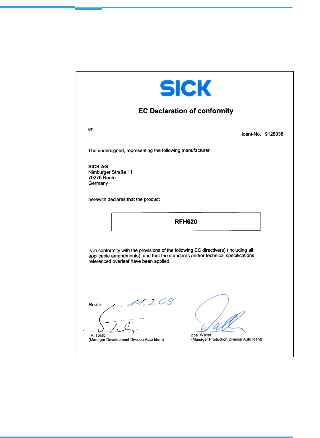
Chapter 11 Operating Instructions
Radio Frequency RFH620 Interrogator
68 © SICK AG · Division Auto Ident · Germany · All rights reserved 8013105/0000/2009-05-12
Appendix
11.5 EC Declaration of Conformity
The figure shows a scaled down version of the EC Declaration of Conformity (page 1) for the
interrogator RFH620.
>The complete EC Declaration of Conformity and the list of device versions and the stan-
dards met can be requested from SICK AG.
Fig. 11-2: EC Declaration of Conformity for the interrogator (page 1, scaled down version)

Operating Instructions Chapter 11
RFH620 Interrogator
Appendix
8013105/0000/2009-05-12 © SICK AG · Division Auto Ident · Germany · All rights reserved 69
11.6 FCC authorisation
The documentation for FCC authorisation is not available for the market launch of RFH620
in May 2009. More information on request.

8013105/0000/2009-05-12 · DWF <PM6.5/FM8.0/PDF>/VD · Printed in Germany · Subject to change without notice · The specified product features and technical data do not represent any guarantee · 05 Pre int63