Siemens Aktiengesellschaft 6021112 WIRELESS GATEWAY/ANCHOR for identification and localization in the WIRELESS LOCATION SYSTEM User Manual 2013 03 14 WIRELESS THR Anchor
Agilion GmbH WIRELESS GATEWAY/ANCHOR for identification and localization in the WIRELESS LOCATION SYSTEM 2013 03 14 WIRELESS THR Anchor
Contents
- 1. 15a_WIRELESS THR GW UserMan
- 2. 15b_WIRELESS THR ANCHOR UserMan
15b_WIRELESS THR ANCHOR UserMan

WIRELESS THR ANCHOR
UserManual
Benutzerhandbuch

FCC ID: SCF6021112
This device complies with part 15 of the FCC Rules.
Operation is subject to the following two conditions: (1) This device may not cause harmful interfer-
ence, and (2) this device must accept any interference received, including interference that may cause
undesired operation.
Modifications not expressly approved by this company could void the user's authority to operate the
equipment.
Note: This equipment has been tested and found to comply with the limits for a Class A digital de-
vice, pursuant to part 15 of the FCC Rules. These limits are designed to provide reasonable protec-
tion against harmful interference when the equipment is operated in a commercial environment. This
equipment generates, uses, and can radiate radio frequency energy and, if not installed and used in
accordance with the instruction manual, may cause harmful interference to radio communications.
Operation of this equipment in a residential area is likely to cause harmful interference in which case
the user will be required to correct the interference at his own expense.
This device and its antenna must not be co-located or operating in conjunction with any other antenna
or transmitter.
This device has been designed to operate with the antennas listed below, and having a maximum gain
of 6 dB. Antennas not included in this list or having a gain greater than 6 dB are strictly prohibited for
use with this device. The required antenna impedance is 50 ohms.
IC: 10971A-6021112
This device complies with Industry Canada licence-exempt RSS standards.
Operation is subject to the following two conditions: (1) This device may not cause interference, and
(2) this device must accept any interference, including interference that may cause undesired opera-
tion of the device.
This device has been designed to operate with the antennas listed below, and having a maximum gain
of 6 dB. Antennas not included in this list or having a gain greater than 6 dB are strictly prohibited for
use with this device. The required antenna impedance is 50 ohms.
Le présent appareil est conforme aux CNR d'Industrie Canada applicables aux appareils radio
exempts de licence.
L'exploitation est autorisée aux deux conditions suivantes : (1) l'appareil ne doit pas produire de
brouillage, et (2) l'utilisateur de l'appareil doit accepter tout brouillage radioélectrique subi, même si le
brouillage est susceptible d'en compromettre le fonctionnement.
Ce dispositif a été conçu pour fonctionner avec les antennes indiquées ci-dessous, et
ayant un gain maximum de 6 dB. Il est strictement interdit d’utiliser les antennes ne figurant pas dans
cette liste ou présentant un gain supérieur à 6 dB avec ce dispositif. L’impédance d’antenne requise
est 50 ohms.
Use the following Agilion Antennas only:
• Omni/4.5dBi/N-M
• Omni/6dBi/N-F/360°

20130325-6021214-UM 1 EN
Table of contents
English
1 Scope of delivery .......................................................................................................... 2
2 Functionality ................................................................................................................. 3
3 Layout and Connections ............................................................................................... 4
3.1 Connectors and Indicators........................................................................................ 5
3.2 Pin-Assignment ......................................................................................................... 5
4 Initial operation and installation ................................................................................. 7
5 Troubleshooting ........................................................................................................... 8
5.1 General errors ........................................................................................................... 8
6 Technical data............................................................................................................... 9
7 Declaration of Conformity ........................................................................................... 10

2 20130325-6021214-UM EN
1 Scope of delivery
• 1 WIRELESS THR ANCHOR
• 1 Power plug (5-pole)
• 1 User manual

20130325-6021214-UM 3 EN
2 Functionality
The anchor nodes are fixed at a steady position in the localization network. They are basing points
for positioning and could be used for forwarding of position information as well.
4 20130325-6021214-UM EN
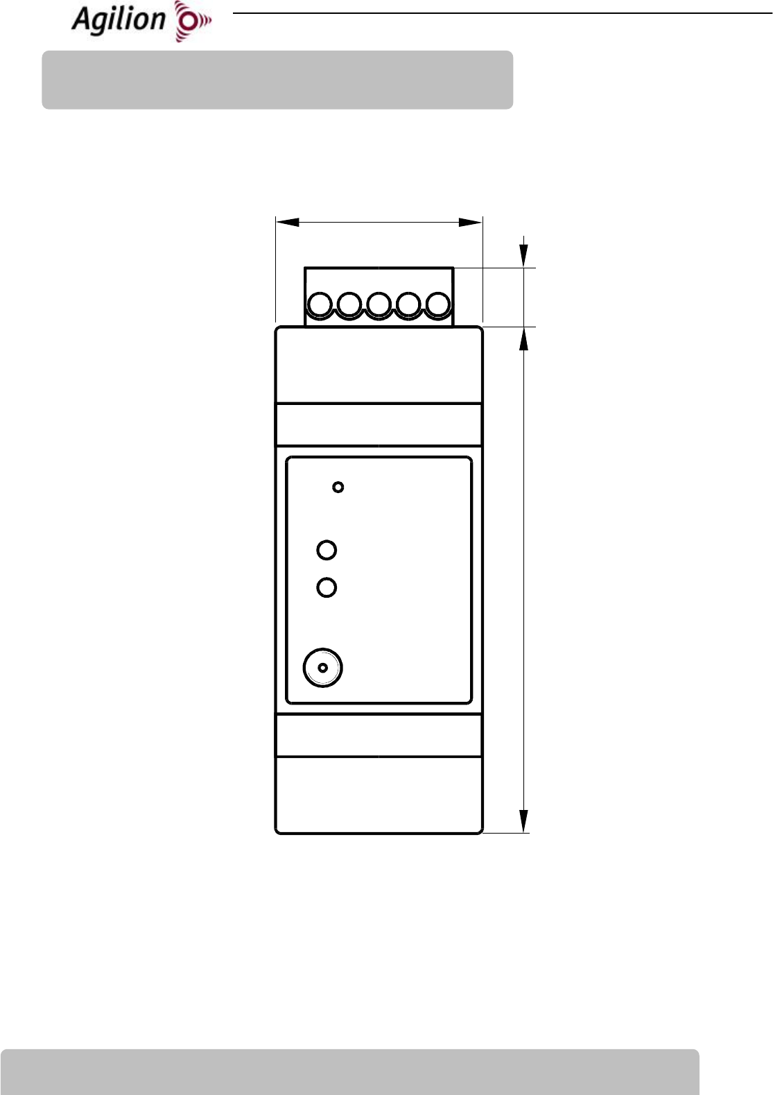
3 Layout and Connections
97 86 10
P1
86mm
35
mm
10mm
P3
D1
D2
S1

20130325-6021214-UM 5 EN
3.1
Connectors and Indicators
Connection /Indication Specification
S1 Push Button, Factory Defaults
P1 - POWER Power supply connector
P3 - Antenna RP-SMA antenna connection
D1 - Radio-LED Indication of wireless transmissions
D2 - Power-LED On when running, blinking on error
3.2
Pin-Assignment
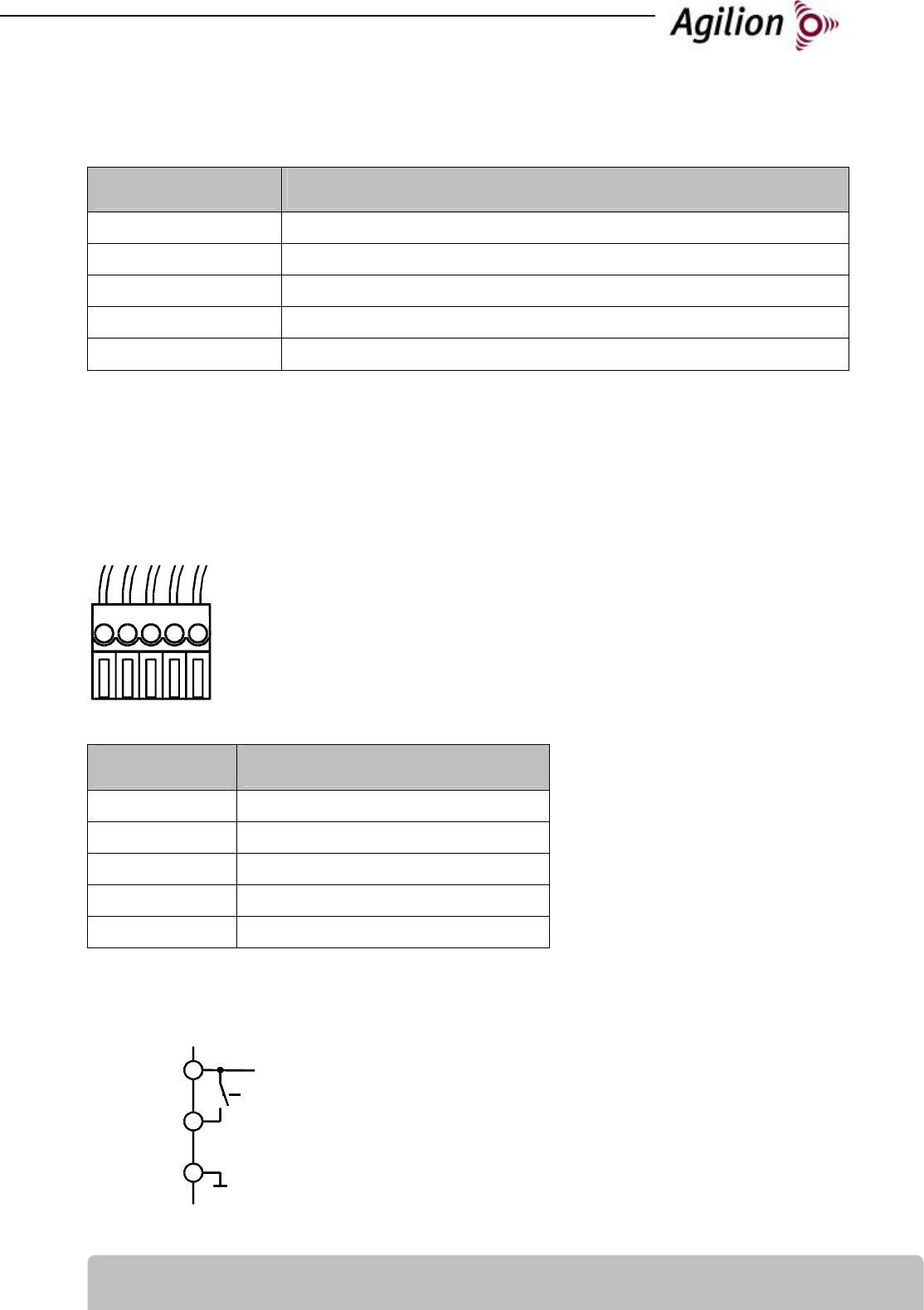
P1 - POWER - Connector
5-pole connector with clamping screw
0.13 mm2 to 3.3 mm2
Reorder with order number: 6020154
Pin Description
6 Alarm switsch
7 GND (Ground)
8 GND (Ground)
9 8 to 30 V DC
10 not Used
Alarm switch - Pin 6
The high side switch power input Pin 9 to the digital output line Pin 6.
Output Voltage: 0 (disabled) or Power Input Voltage (enabled)
Maximum Output Current: 100 mA
P1
6 7 8 9 10
Power Supply
Alarm Switch
Ground
9
6
8
GND
9
6
7
GND

6 20130325-6021214-UM EN
P3 - Antenna – RP-SMA Connector
Pin Description
1 Antenna
Shield Ground

20130325-6021214-UM 7 EN
4 Initial operation and installation
1. The antenna (P3) must be attached to the RP-SMA-connection at the WIRELESS module.
Warning: Do operate the WIRELESS Module without antenna connected. While changing or
removing antenna switch the device off or remove power cable.
Notice: The antennas should be justified in same direction on all WIRELESS modules.
Notice: The WIRELESS modules should be placed line of sight and in a high position for op-
timised wireless data transmission.
2. Set up power connection (P1). During start-up all LED’s are flashing once. The power-LED
(D2) keeps on lighting.
3. The WIRELESS modules must be protected against humidity.

8 20130325-6021214-UM EN
5 Troubleshooting
5.1
General errors
Effect Reason Action
Module does not work, Power-
LED is off
No power connection or not
switched on
Check power supply, switch
WIRELESS module on
Flashing Power-LED at normal
operation
Module Error Switch WIRELESS module off and
on for reset, if error occurs
frequently contact
service@agilion.de
20130325-6021214-UM 9 EN
6 Technical data
Radio
Wireless technology IEEE 802.15.4a nanoLOC,
Modulation: Chirp Spread Spectrum (CSS)
Data rates 1 MBit
Operating frequency 2.45 GHz ISM-Band
Chirp-bandwidth 80 MHz
Output power max. 100 mW, adjustable
Range @ 1 MBit Indoor max. 90 m, Outdoor max. 1,000 m
Connectors and Power
Supply voltage 8 to 30 V DC
Power consumption max. 0.2 A
Antenna interface RP-SMA (male)
Power connector 5-pole connector with clamping screw, 0.13 mm2 to 3.3 mm2,
Order#: 6020154
Environment
Case Plastic housing
IP-protection IP 40
Dimension 35 x 86 x 58 mm
Weight 80 g
Mounting DIN 60 715 TH35
Temperature range -40 to +70°C

10 20130325-6021214-UM EN
7 Declaration of Conformity
The Agilion GmbH declares the conformity of
WIRELESS THR ANCHOR
according to the requirements of the standards:
EN300328
EN 301489-1
EN 301489-17
EN 61000-3-2:2000+A1:2005
EN 61000-3-3:1995+A1:2001
EN 55022:1998+A1:2000+A2:2003
EN 55022:1994+A1:1995+A2:1997
EN 55024:1998+A1:2001+A2:2003
EN 60950-1
WIRELESS THR ANCHOR therefore complies with the EC-directives:
R&TTE 1999/5/EC
89/336/EEC
73/23/EWG
This declaration applies to all devices bearing the symbol. Validity is lost if modifications are
made to the product.
Dipl.-Inf. Sven Sieber Dipl.-Kfm.(FH) Andreas Werner
(Managing Director) (Managing Director)
Agilion GmbH
Blankenauer Str. 74
09113 Chemnitz
Germany

20130325-6021214-UM 1 DE
Inhaltsverzeichnis
Deutsch
1 Lieferumfang ................................................................................................................. 2
2 Überblick....................................................................................................................... 3
3 Mechanik und Anschlüsse ............................................................................................ 4
3.1 Anschlüsse und Anzeigen.......................................................................................... 5
3.2 Pin-Belegung ............................................................................................................. 5
4 Inbetriebnahme und Installation ................................................................................. 7
5 Behebung von Störungen ............................................................................................. 8
5.1 Allgemeine Fehler...................................................................................................... 8
6 Technische Daten ......................................................................................................... 9
7 Konformitätserklärung ............................................................................................... 10

2 20130325-6021214-UM
DE
1 Lieferumfang
• 1 WIRELESS THR ANCHOR
• 1 Power-Stecker (5-polig)
• 1 Benutzerhandbuch

20130325-6021214-UM 3 DE
2 Überblick
Die Ankerknoten besitzen eine feste Position im Lokalisierungsnetzwerk. Sie fungieren als Refe-
renzpunkte zur Lokalisierung und ermöglichen die Weiterleitung von Positionsdaten.
4 20130325-6021214-UM
DE
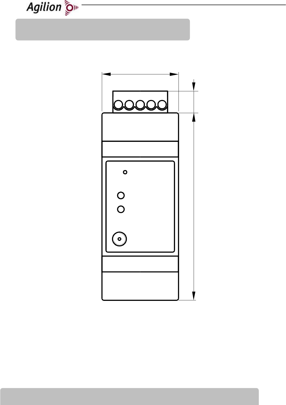
3 Mechanik und Anschlüsse
97 86 10
P1
86mm
35
mm
10mm
P3
D1
D2
S1
20130325-6021214-UM 5 DE
3.1
Anschlüsse und Anzeigen
Anschluss / Anzeige Beschreibung
S1 Taster, Werkseinstellungen
P1 - POWER Stromversorgung
P3 - Antenne RP-SMA - Antennenanschluss
D1 - Radio-LED LED zur Signalisierung der Funkaktivität (Senden und Empfangen)
D2 - Power-LED LED leuchtet wenn Gerät in Betrieb, blinkt bei Fehler
3.2
Pin-Belegung
P1 - POWER - Steckverbinder
5-poliger Steckverbinder mit Schraubklemmen
0,13 mm2 bis 3,3 mm2
Nachbestellung mit Bestellnummer: 6020154
Pin Beschreibung
6 Meldeausgang
7 GND (Masse)
8 GND (Masse)
9 8 bis 30 V DC
10 nicht verwendet
Meldeausgang - Pin 6
Ein High-Side-Switch schaltet die Versorgungsspannung auf den digitalen Ausgang Pin 6.
Ausgangsspannung: 0 (ausgeschaltet) oder Eingansspannung
(eingeschaltet)
Maximaler Ausgangsstrom: 100 mA
P1
6 7 8 9 10
Versorgungs-
spannung
Melde-
ausgang
Masse
9
6
8
GND
9
6
7
GND

6 20130325-6021214-UM
DE
P3 - Antenne - RP-SMA Stecker
Pin Beschreibung
1 Antenne
Shield GND (Masse)

20130325-6021214-UM 7 DE
4 Inbetriebnahme und Installation
1. Antenne an RP-SMA-Anschluss (P3) anschließen.
Achtung: Das WIRELESS Modul darf nicht ohne Antenne betrieben werden. Zum Wechseln
oder Entfernen der Antenne ist das Gerät auszuschalten bzw. stromlos zu schalten.
Hinweis: Die Antennen sollten an allen WIRELESS-Modulen gleich ausgerichtet sein.
Hinweis: Um eine optimale Übertragung zu ermöglichen, sollten die WIRELESS-Module mög-
lichst weit oben angebracht werden und Sichtverbindung haben.
2. Anschluss der Stromversorgung an den Power-Eingang (P1). Dabei leuchten alle LEDs initial
auf. Die Power-LED (D2) leuchtet permanent.
3. Die WIRELESS-Module müssen vor Feuchtigkeit geschützt werden.

8 20130325-6021214-UM
DE
5 Behebung von Störungen
5.1
Allgemeine Fehler
Fehlererkennung Fehlerursache Fehlerbehebung
WIRELESS-Modul reagiert
nicht, LED leuchtet nicht
Modul nicht angeschlossen
oder nicht eingeschaltet
Stromversorgung des Moduls
prüfen, Modul anschalten
Blinkende Power-LED
während des Betriebs
Fehler in Modul Rücksetzen durch Aus- & An-
schalten des Moduls; tritt der
Fehler mehrfach auf, kontaktie-
ren sie bitte service@agilion.de
20130325-6021214-UM 9 DE
6 Technische Daten
Funk
Funkverfahren IEEE 802.15.4a nanoLOC,
Modulationsverfahren: Chirp Spread Spectrum (CSS)
Datenrate 1 MBit
Frequenzbereich 2,45 GHz ISM-Band
Chirp-Bandbreite 80 MHz
Sendeleistung max. 100 mW, einstellbar
Reichweite @ 1 MBit Indoor max. 90 m, Outdoor max. 1.000 m
Anschlüsse und Energieversorgung
Spannung 8 bis 30 V DC
Energieaufnahme max. 0,2 A
Antennenanschluss RP-SMA-Stecker
Power-Steckverbinder 5-poliger Steckverbinder mit Schraubklemme, 0,13 mm2 bis 3,3 mm2,
Bestell-Nr.: 6020154
Umgebung
Gehäuse Plastikgehäuse
IP-Schutzart IP 40
Abmessungen 35 x 86 x 58 mm
Gewicht 80 g
Befestigungsmöglichkeiten Normschiene DIN 60 715 TH35
Temperaturbereich -40 bis +70°C

10 20130325-6021214-UM
DE
7 Konformitätserklärung
Die Agilion GmbH erklärt die Konformität von
WIRELESS THR ANCHOR
mit den Anforderungen der Normen:
EN300328
EN 301489-1
EN 301489-17
EN 61000-3-2:2000+A1:2005
EN 61000-3-3:1995+A1:2001
EN 55022:1998+A1:2000+A2:2003
EN 55022:1994+A1:1995+A2:1997
EN 55024:1998+A1:2001+A2:2003
EN 60950-1
WIRELESS THR ANCHOR entspricht den EG-Richtlinien:
R&TTE 1999/5/EC
89/336/EEC
73/23/EWG
Diese Erklärung gilt für alle Geräte, die das - Zeichen tragen. Bei Veränderungen an dem Pro-
dukt geht die Gültigkeit verloren.
Dipl.-Inf. Sven Sieber Dipl.-Kfm.(FH) Andreas Werner
(Geschäftsführer) (Geschäftsführer)
Agilion GmbH
Blankenauer Str. 74
09113 Chemnitz

Notes/Notizen:

Agilion GmbH
Blankenauer Straße 74
09113 Chemnitz
Germany
Tel.: +49 - (0)371 - 45 00 48-0
Fax.: +49 - (0)371 - 45 00 48-11
www.agilion.de
service@agilion.de
Management/Geschäftsführung:
Sven Sieber
Andreas Werner
HR B 21249 Chemnitz
USt.-IdNr.: DE236591552