Siemens Canada Siemens Milltronics Process Instruments LR560 SITRANS LR560 Tank Level Probing Radar User Manual KB01 LR560 HART
Siemens Canada Ltd. - Siemens Milltronics Process Instruments SITRANS LR560 Tank Level Probing Radar KB01 LR560 HART
Contents
User Manual 1
![7ML19985KB01 SITRANS LR560 (mA/HART) – INSTRUCTION MANUAL Page 5mmmmmSITRANS LR560SITRANS LR560 OverviewSITRANS LR560 is a 2-wire, 78 GHz FMCW radar level transmitter for continuous monitoring of solids in vessels to a range of 100 m (329 ft). The plug and play performance is ideal for all solids applications, including those with extreme dust and high temperatures to +200 °C (+392 °F). The device is an electronic circuit coupled to a lens antenna and flange for quick and easy positioning. The main benefits of using 78 GHz over devices using lower frequency are:• very narrow beam, so device is insensitive to mounting nozzle interference and vessel obstructions.• short wavelength yields very good reflection properties on sloped solids, so aiming towards material angle of repose is usually not necessary.The technology is very tolerant to buildup on the lens antenna, however an air purge inlet is provided for periodic cleaning if required.SITRANS LR560 supports HART communication protocol, and SIMATIC PDM software. Signals are processed using Process Intelligence which has been field-proven in over 1,000,000 applications worldwide (ultrasonic and radar).ProgrammingSITRANS LR560 is very easy to install and configure via an optional graphical local display interface. You can modify the built-in parameters either locally via the push buttons or using the infra-red handheld programmer, or from a remote location using one of the following options:• HART (using 375 handheld Field Communicator, SIMATIC PDM, AMS, Pactware FDT/DTM)• PROFIBUS PA (using SIMATIC PDM, FDT [such as PACTware or Fieldcare]) (See SITRANS LR560 (PROFIBUS PA) Instruction Manual for more information.)• Foundation Fieldbus FF (using handheld 375 Field Communicator, FF host system or AMS Device Manager) [See SITRANS LR560 (Foundation Fieldbus) Instruction Manual for more information.]Once programmed, the graphic Local Display Interface (LDI) can be removed if desired and used to transfer parameters to multiple SITRANS LR560s.](https://usermanual.wiki/Siemens-Canada-Siemens-Milltronics-Process-Instruments/LR560.User-Manual-1/User-Guide-1395471-Page-11.png)
![7ML19985KB01 SITRANS LR560 (mA/HART) – INSTRUCTION MANUAL Page 23mmmmmWiring5. Connect the wires to the terminals as shown: the polarity is identified on the terminal block.6. Ground the instrument according to local regulations.7. Tighten the gland to form a good seal.8. Replace optional display and device lid.9. Tighten locking screw.Connecting HART1)2)1) Depending on the system design, the power supply may be separate from the PLC, or integral to it.2) HART resistance (total loop resistance, that is, cable resistance plus 250 Ohm [resistor]) must be less than 550 Ohm for the device to function properly.cable gland (or NPT cable entry)cable shieldinstrument shield connectionactive PLCHART modemSITRANS LR560power supply1)Typical PLC/mA configuration with HARTR= 250 Ω2)HART communicator](https://usermanual.wiki/Siemens-Canada-Siemens-Milltronics-Process-Instruments/LR560.User-Manual-1/User-Guide-1395471-Page-29.png)
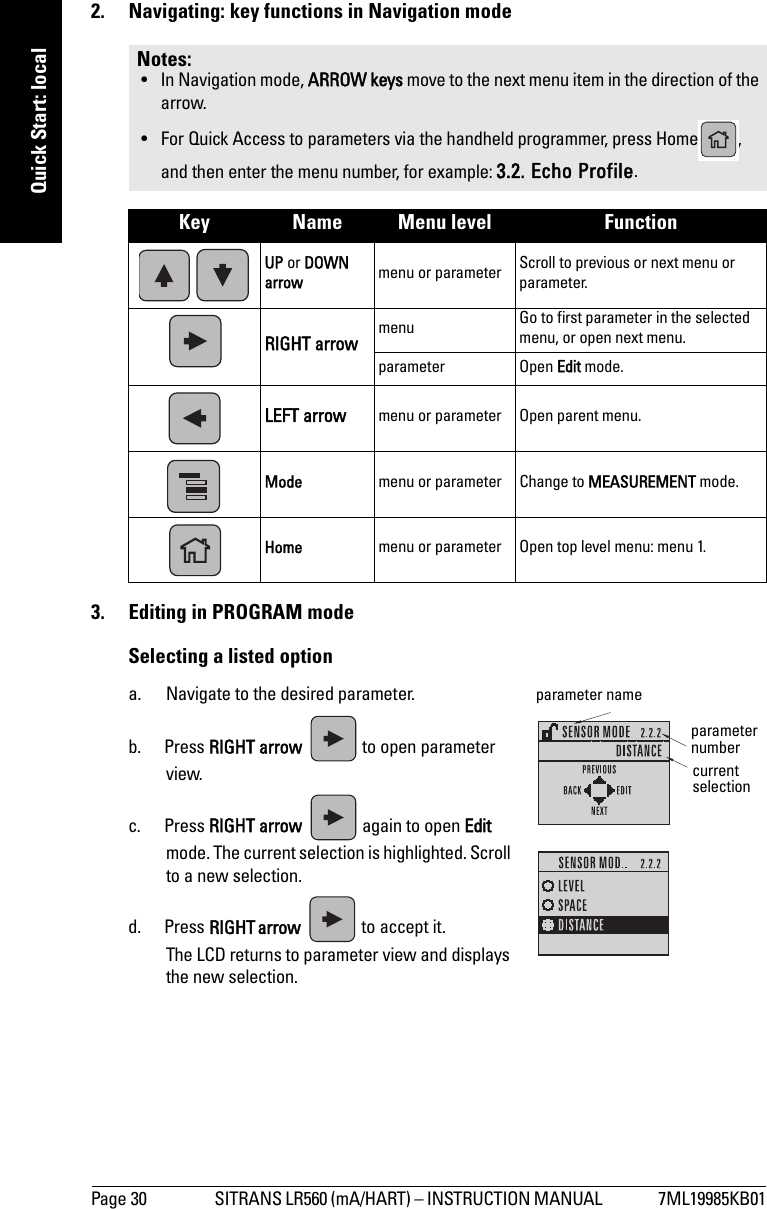
![7ML19985KB01 SITRANS LR560 (mA/HART) – INSTRUCTION MANUAL Page 27mmmmmQuick Start: localThe LCD DisplayMeasurement mode display: 1)2)Normal operationFault presentPROGRAM mode displayNavigation view• A visible menu bar indicates the menu list is too long to display all items.• The depth of the item band on the menu bar indicates the length of the menu list: a deeper band indicates fewer items.• The position of the item band indicates the approximate position of the current item in the list. A band halfway down the menu bar indicates the current item is halfway down the list. 1) Press UP or DOWN arrow to switch2) In response to a key press request. For details, see Key functions in Measurement mode on page 28.M[]LEVEL21.40 °CDATA EXCH.18.911 – toggle indicator1) for PV or SV (primary or secondary values)2 – selected operation: level, space, or distance3 – measured value (level, space, or distance)4 – units5 – bar graph indicates level6 – secondary region indicates on request2) electronics temperature, echo confidence, loop current, or distance7 – text area displays status messages 8 – device status indicator67813425S: 0 LOE7 – text area displays a fault code and an error message8 – service required icon appearscurrent item numbercurrent itemcurrent menu menu baritem bandparameter value/selectionparameter nameparameter numberParameter view Edit view](https://usermanual.wiki/Siemens-Canada-Siemens-Milltronics-Process-Instruments/LR560.User-Manual-1/User-Guide-1395471-Page-33.png)
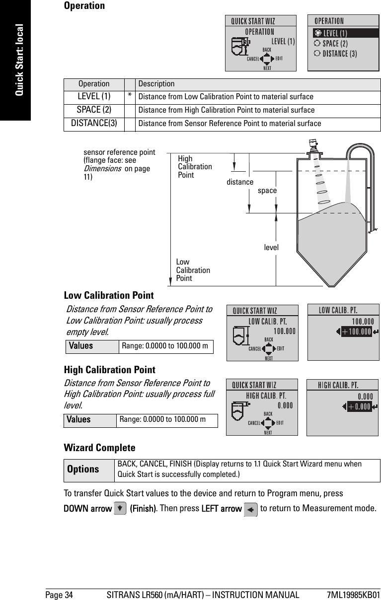
![Page 36 SITRANS LR560 (mA/HART) – INSTRUCTION MANUAL 7ML19985KB01mmmmmQuick Start: localLevel application exampleThe application is a vessel that takes an average 3 hours (180 minutes) to fill and 3 weeks to empty.Fill rate = 0.08 m/minute [(Low Cal Pt. minus High Cal Pt.) / fastest of fill or empty time]= (15.5 m – 1 m) / 180 min. = 14.5 m /180 min. = 0.08 m/min.Therefore SLOW response rate (0.1 m/minute) can be selected.Quick Start Parameter Setting Description Vessel STEEL Selects vessel construction material.Response Rate SLOW Resets Fill Rate/ Empty Rate to 0.1 m/minute.Units M Sensor measurement units.Operation LEVEL (1) Material level referenced from Low Cal. Point.Low Calibration Point 15.5 Process empty level.High Calibration Point 1.0 Process full level.sensor reference point Level Low Cal. PointHigh Cal. Point15.5 m1.0 m LR560](https://usermanual.wiki/Siemens-Canada-Siemens-Milltronics-Process-Instruments/LR560.User-Manual-1/User-Guide-1395471-Page-42.png)
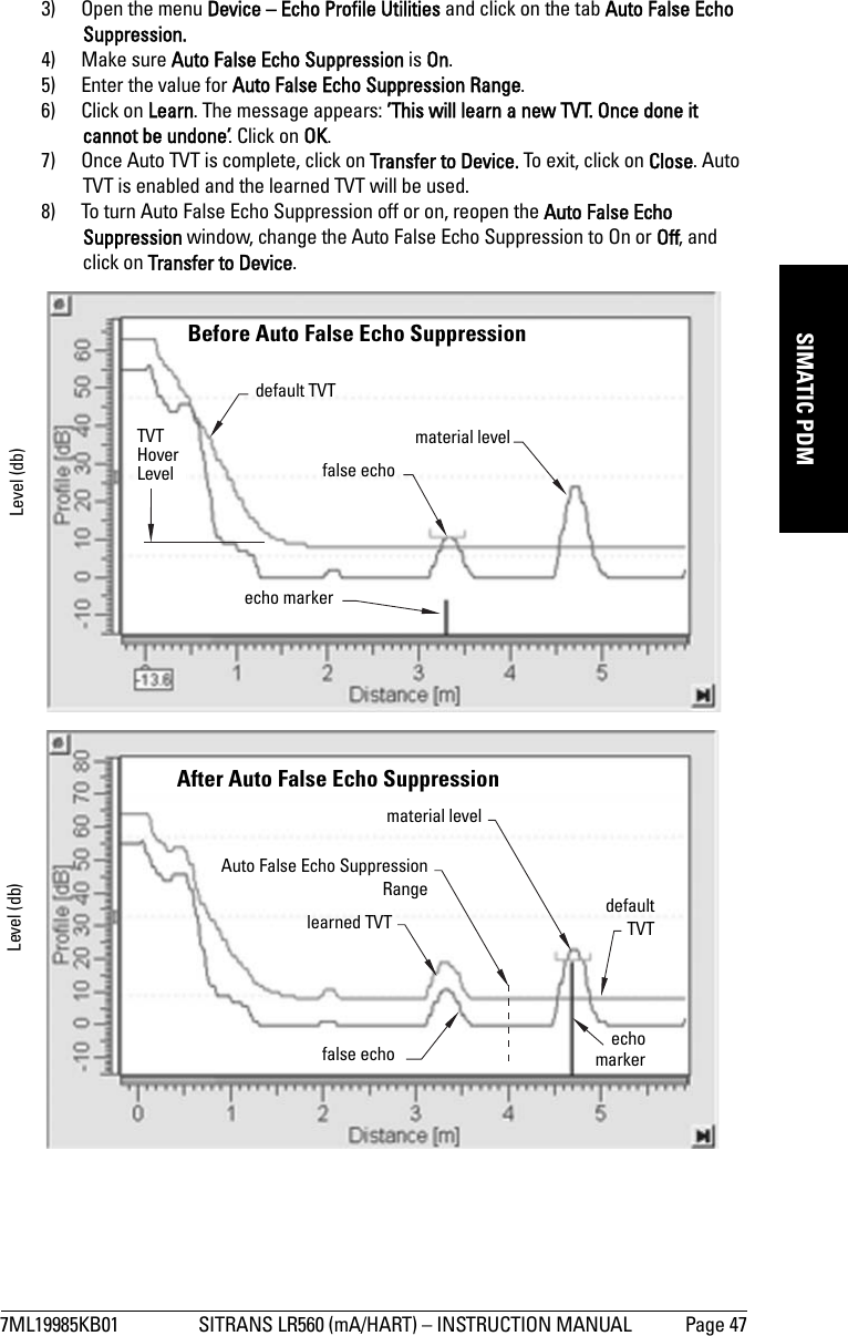
![7ML19985KB01 SITRANS LR560 (mA/HART) – INSTRUCTION MANUAL Page 49mmmmmSIMATIC PDM3) Click on Write.4) Click on Read, to see the effects of your modification.5) Click on Snooze to add a year to the Total Expected Device Life.To set Service/Calibration schedules:1) Open the menu Device – Maintenance, and click on the Service/Calibration Schedule tab. 2) Modify desired values, and if desired, set reminders for either or both of Reminder 1 (Required)/Reminder 2 (Demanded).3) Click on Write.4) Click on Read, to see the effects of your modification.5) Click on Service/Calibration Performed to reset the schedule.Select Analog OutputAllows you to set the mA Output to report Level, Distance, or Space. 1) Open the menu Device – Select Analog Output. 2) The Select Analog Output window displays the current setting: click on OK.3) Select a different setting and click on OK.4) The Select Analog Output window displays the new setting: click on OK.Self TestChecks memory (RAM and Flash). If there are no errors, returns the message ’Self Test OK.’ If errors are found, returns the message ’Self Test Fails’.Open the menu Device – Self Test, select the option Yes and click on OK.Loop TestAllows you to input a simulated value (4 mA, 20 mA, or a user-defined value) in order to test the functioning of the mA connections during commissioning or maintenance of the device. (The range is 3.56 mA to 22.6 mA: see Signal Processing (2.7.) on page 88.)To simulate a user-defined mA value:1) Open the menu Device – Loop Test. 2) Select Other, enter the new value, and click on OK. The message ’Field Device fixed at [new value]’ appears. Click on OK. The Loop Test window remains open.3) When you are ready to end simulation, select End and click on OK to return the device to the actual output value.Configuration Flag ResetTo reset the configuration flag to zero, open the menu Device – Configuration Flag Reset and perform a reset.Note: The simulated AO (Analog Output) value influences output to the control system.](https://usermanual.wiki/Siemens-Canada-Siemens-Milltronics-Process-Instruments/LR560.User-Manual-1/User-Guide-1395471-Page-55.png)
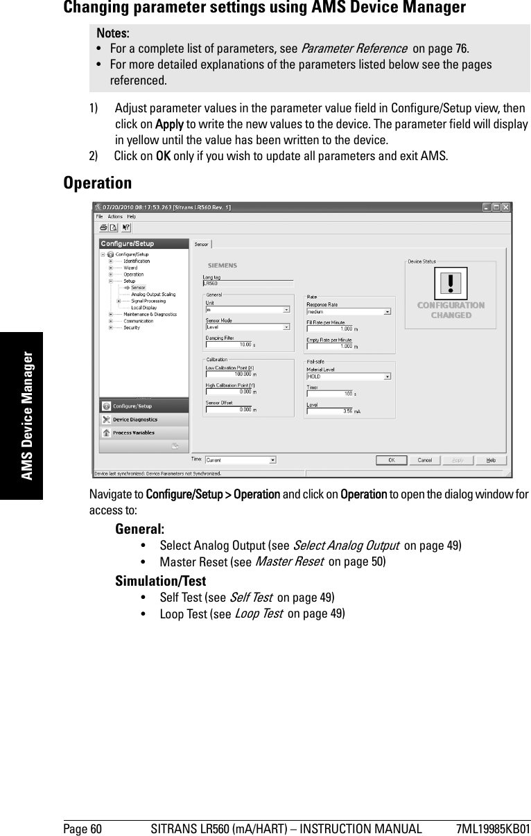
![7ML19985KB01 SITRANS LR560 (mA/HART) – INSTRUCTION MANUAL Page 61mmmmmAMS Device ManagerSetupSensor Navigate to Configure/Setup > Setup and click on Sensor for access to:General [see Sensor (2.2.) on page 80]•Unit•Sensor Mode• Damping FilterCalibration [see Calibration (2.3.) on page 81]• Low Calibration Point• High Calibration Point• Sensor OffsetRate [see Rate (2.4.) on page 82]• Response Rate• Fill rate/minute• Empty rate/minuteFail-safe [see Fail-safe (2.5.) on page 84]• Material level• Timer•LevelNote: For more detailed explanations of the parameters listed below, see the pages referenced.](https://usermanual.wiki/Siemens-Canada-Siemens-Milltronics-Process-Instruments/LR560.User-Manual-1/User-Guide-1395471-Page-67.png)
![Page 62 SITRANS LR560 (mA/HART) – INSTRUCTION MANUAL 7ML19985KB01mmmmmAMS Device ManagerAnalog Output ScalingNavigate to Configure/Setup > Setup and click on Analog Output Scaling for access to:Analog Output Scaling [see Analog Output Scaling (2.6.) on page 85]• Current Output Function• Start of scale (=4mA)• Full Scale (=20mA)• Control Range (lower limit)• Control Range (upper limit)Signal Processing](https://usermanual.wiki/Siemens-Canada-Siemens-Milltronics-Process-Instruments/LR560.User-Manual-1/User-Guide-1395471-Page-68.png)
![7ML19985KB01 SITRANS LR560 (mA/HART) – INSTRUCTION MANUAL Page 63mmmmmAMS Device ManagerSignal Processing (continued)GeneralNavigate to Configure/Setup > Setup > Signal Processing and click on General for access to:Range [see Signal Processing (2.7.) on page 88]•Near Range•Far RangeEcho Select [see Echo select (2.7.3.) on page 88]• Algorithm•Position Detect• Echo Threshold• CLEF Range•Echo MarkerSampling [see Sampling (2.7.4.) on page 91]•Echo Lock• Sampling Up• Sampling Down• Echo Lock WindowEcho Quality• Confidence• Echo StrengthFiltering• Narrow Echo Filter• Reform EchoTVTModify the TVT to screen out false echoes [see Shaper Mode on page 94].](https://usermanual.wiki/Siemens-Canada-Siemens-Milltronics-Process-Instruments/LR560.User-Manual-1/User-Guide-1395471-Page-69.png)
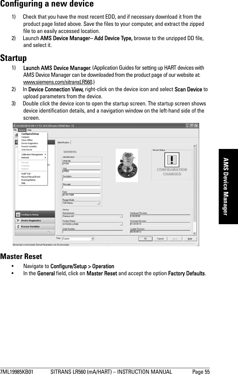
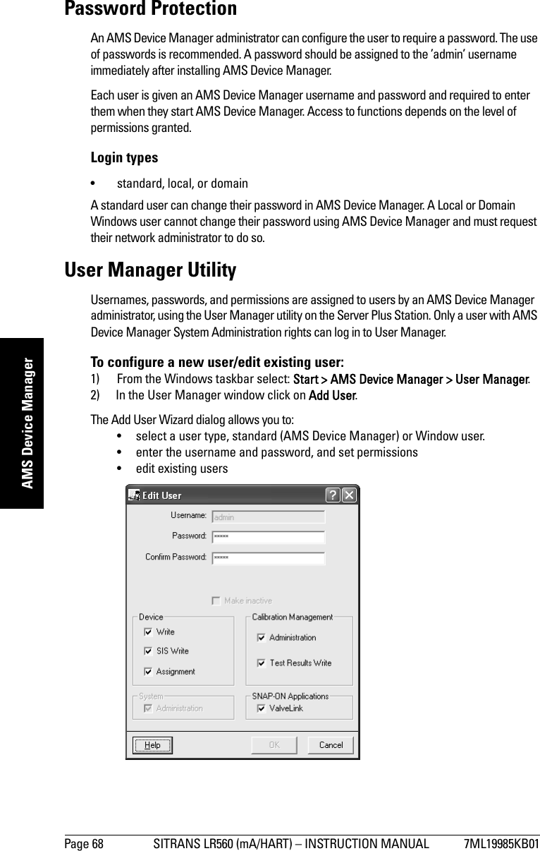
![Page 64 SITRANS LR560 (mA/HART) – INSTRUCTION MANUAL 7ML19985KB01mmmmmAMS Device ManagerNavigate to Configure/Setup > Setup > Signal Processing and click on TVT. Click on one of the two tabs to access the parameters listed:TVT Setup [see TVT setup (2.8.) on page 93]• Auto False Echo Suppression• Auto False Echo Suppression Range• Hover Level• Shaper ModeTVT Shaper• Shaper breakpoints 1 to 120. (Turn TVT Setup/Shaper Mode on to activate.)Manual TVT Curve Displays the effects of the TVT shaper modifications. Navigate to Configure/Setup > Setup > Signal Processing and click on Manual TVT Curve.Echo Profile• Navigate to Configure/Setup > Setup > Signal Processing and click on Echo Profile.• To view a previous profile, click the drop-down arrow on the Time field and select the desired profile (note: available only using AMS version 10.1 or later).Local Display Navigate to Configure/Setup > Setup > Local Display for access to: •Language• LCD Contrast [see LCD Contrast (4.6.) on page 104]• LCD Backlight [see LCD Backlight (4.5.) on page 103]Maintenance and DiagnosticsNavigate to Maintenance and Diagnostics for access to: Remaining Device Lifetime [see Remaining Device Lifetime (3.6.) on page 98]• Lifetime expected• Remaining Lifetime• Time in Operation• Activation of Reminders• Reminder 1 before Lifetime (Required)• Reminder 2 before Lifetime (Demanded)a) Open the window Remaining Device Lifetime.b) After modifying values/units as required, click on Apply to accept the change.](https://usermanual.wiki/Siemens-Canada-Siemens-Milltronics-Process-Instruments/LR560.User-Manual-1/User-Guide-1395471-Page-70.png)
![7ML19985KB01 SITRANS LR560 (mA/HART) – INSTRUCTION MANUAL Page 65mmmmmAMS Device Managerc) Click on Snooze for 1 Year to add a year to the Total Expected Sensor Life.Remaining Sensor Lifetime [see Remaining Sensor Lifetime (3.7.) on page 100]• Lifetime expected• Time in Operation• Remaining Lifetime• Activation of Reminders• Reminder 1 before Lifetime (Required)• Reminder 2 before Lifetime (Demanded)a) Open the window Remaining Device Lifetime.b) After modifying values/units as required, click on Apply to accept the change. c) Click on Sensor Replaced to reset Remaining Lifetime to 0 hours.d) Click on Snooze for 1 Year to add a year to the Total Expected Sensor Life.](https://usermanual.wiki/Siemens-Canada-Siemens-Milltronics-Process-Instruments/LR560.User-Manual-1/User-Guide-1395471-Page-71.png)
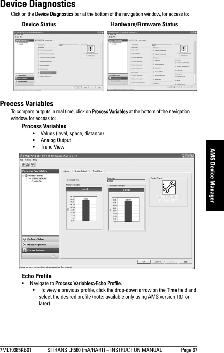
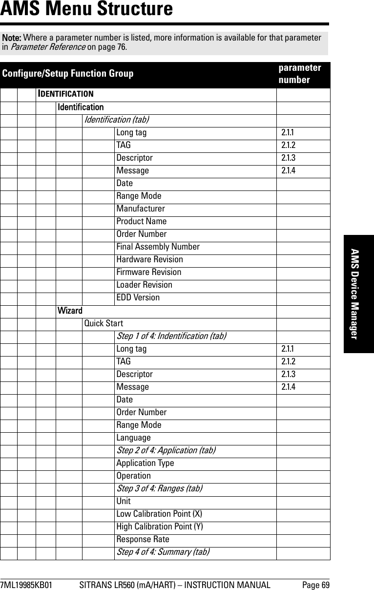
![Page 66 SITRANS LR560 (mA/HART) – INSTRUCTION MANUAL 7ML19985KB01mmmmmAMS Device ManagerService Schedule [see Service Schedule (4.7.) on page 104]•Service Interval• Time since last Service• Time until next Service• Activation of Reminders• Reminder 1 before Service (Required)• Reminder 2 before Service (Demanded)• Click on Service Performed to reset Time Until Next Service to the full service interval.Calibration Schedule [see Calibration Schedule (4.8.) on page 107]• Calibration Interval• Time since last Calibration• Time Until Next Calibration• Activation of Reminders• Reminder 1 before Calibration (Required)• Reminder 2 before Calibration (Demanded)• Click on Calibration Performed to reset Time Until Next Calibration to the full calibration interval.Electronic Temperature• Electronic Temperature • Lowest Value• Highest ValueWear (see Powered Hours (4.3.) on page 103)• Time in Operation (Reset to 0 after clicking Sensor Replaced)• Poweron ResetsCommunicationNavigate to Communication to read the following: Long Tag; Manufacturer’s ID; Device ID; Product ID; Device Revision; EDD Revision; Universal CommandSecurityNavigate to Configure/Setup > Security to access:Remote Access [see Remote Lockout (5.2.) on page 110]• Write ProtectionLocal Access• Local Operation EnableSee also Password Protection on page 68.Note: If access control is changed via the handheld programmer to limit remote access, it can only be reset via the handheld programmer. See Remote Lockout (5.2.) on page 110.](https://usermanual.wiki/Siemens-Canada-Siemens-Milltronics-Process-Instruments/LR560.User-Manual-1/User-Guide-1395471-Page-72.png)
![Page 84 SITRANS LR560 (mA/HART) – INSTRUCTION MANUAL 7ML19985KB01mmmmmParameters2.5. Fail-safe2.5.1. Material LevelDefines the mA output to use when the Fail-safe Timer expires.2.5.2. TimerSets the time to elapse since the last valid reading, before the Fail-safe Level is reported.2.5.3. LevelAllows the user to define the mA value to be reported when the Fail-safe timer expires. Notes: • Default settings in the parameter tables are indicated with an asterisk (*) unless explicitly stated.• The default setting depends whether your device is a standard or NAMUR NE 43-compliant device.a)a) NE43 device part number ends with -Z NO7.Options HI 20.5 mA (max. mA Limit) LO 3.8 mA (min. mA Limit) * HOLD Last valid reading (default 22.6 mA)VALUE User-selected value [defined in Level (2.5.3.): default 3.58 mA]NAMUR NE 43-COMPLIANT DEVICEOptions HI 20.5 mA (max. mA Limit) LO 3.8 mA (min. mA Limit) HOLD Last valid reading * VALUE User-selected value [defined in Level (2.5.3.): default 3.58 mA]Note: When a Loss of Echo occurs Material Level (2.5.1.) determines the material level to be reported when the Fail-safe timer expires. Values Range: 0.00 to 720 secondsDefault: 100 sNotes:•Material Level (2.5.1.) must be set to VALUE to enable the Level value to be reported.Values Range 3.56 mA to 22.6 mADefault 3.56 mA](https://usermanual.wiki/Siemens-Canada-Siemens-Milltronics-Process-Instruments/LR560.User-Manual-1/User-Guide-1395471-Page-90.png)

![7ML19985KB01 SITRANS LR560 (mA/HART) – INSTRUCTION MANUAL Page 139mmmmmF: HART Communications3 Status group 24 Status group 35 Status group 46 Status group 57 Status group 148 Device Status Icon3 Process Variables1 Values 1 Primary2 PV: Distance3 Secondary4 SV: Distance5 Device Status Icon2 Analog Output 1 Distance Range [%]2 Analog Output [mA]3 Device Status Icon3 Trend View1 Trend Values1 Primary2 Secondary2 Trend View3 Device Status IconHART VersionSITRANS LR560 conforms to HART rev. 6.Burst ModeSITRANS LR560 does not support burst mode.HART Multidrop ModeWe do not recommend the use of HART Multidrop Mode.](https://usermanual.wiki/Siemens-Canada-Siemens-Milltronics-Process-Instruments/LR560.User-Manual-1/User-Guide-1395471-Page-145.png)