Siemens 277IWLAN-V211 MobilePanel277FIWLAN RF User Manual III
Siemens AG MobilePanel277FIWLAN RF III
UserManual.wiki
>
Siemens
>
277IWLAN-V211 User Manual
>
User Manual III
Contents
1.
User Manual
2.
User Manual II
3.
User Manual III
4.
User Manual IV
5.
User Manual V
6.
User Manual I
User Manual III
Navigation menu
Upload a User Manual
Namespaces
Wiki Guide
HTML
PDF
Info
Views
User Manual
Discussion / Help
Navigation
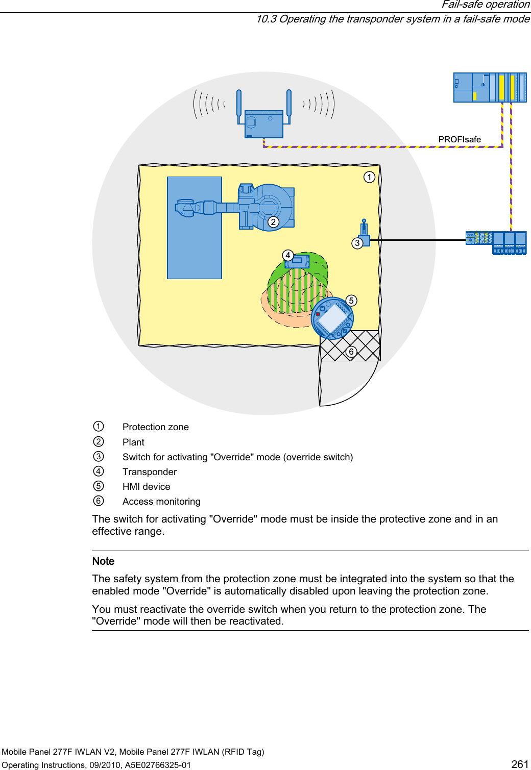
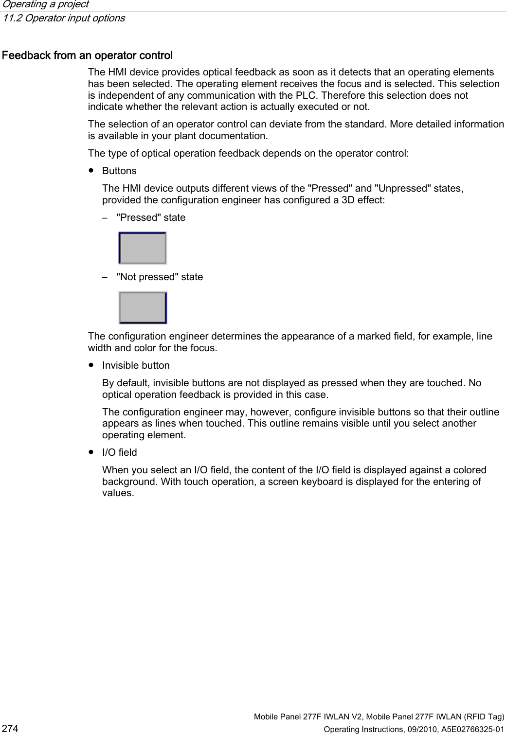
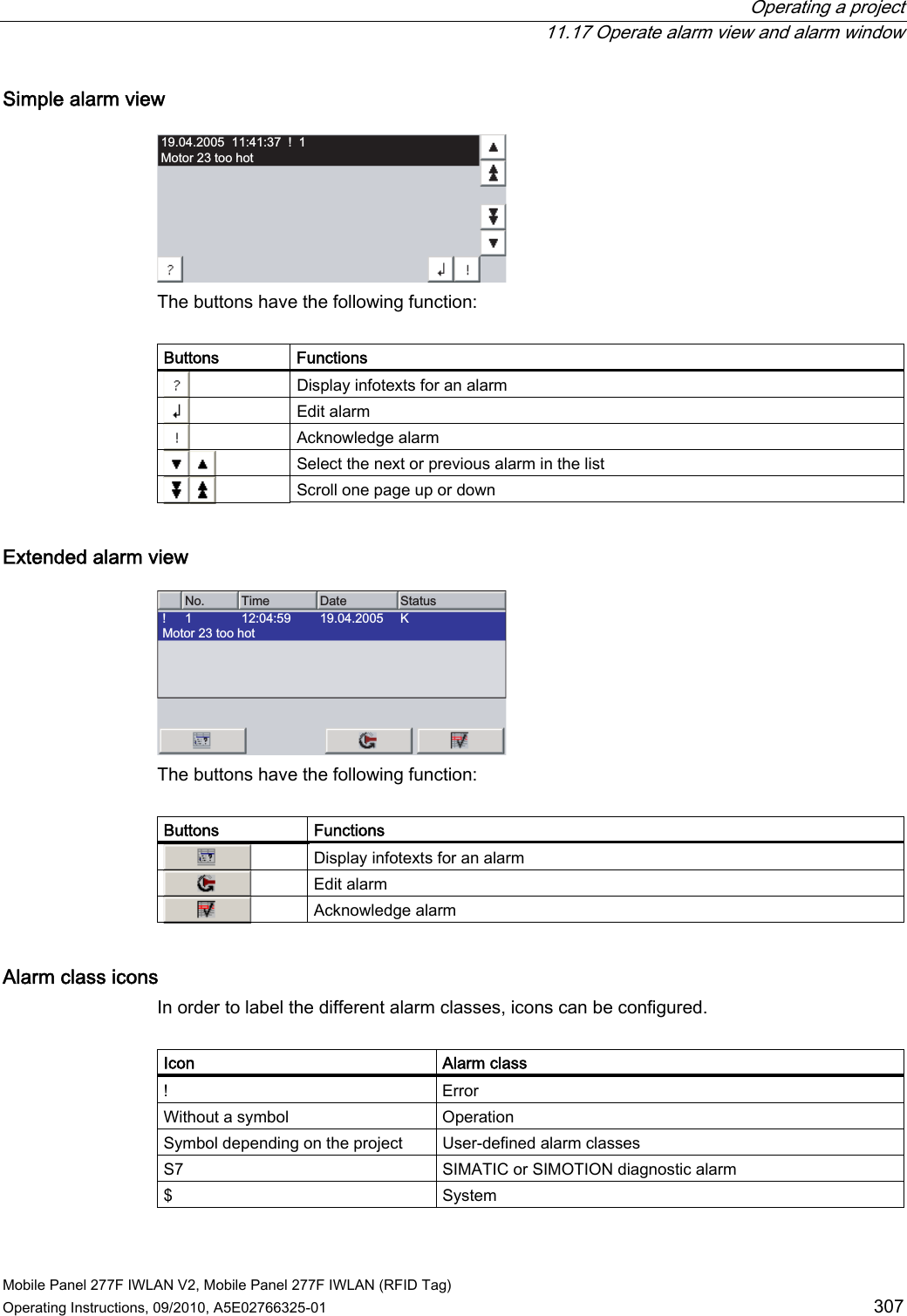
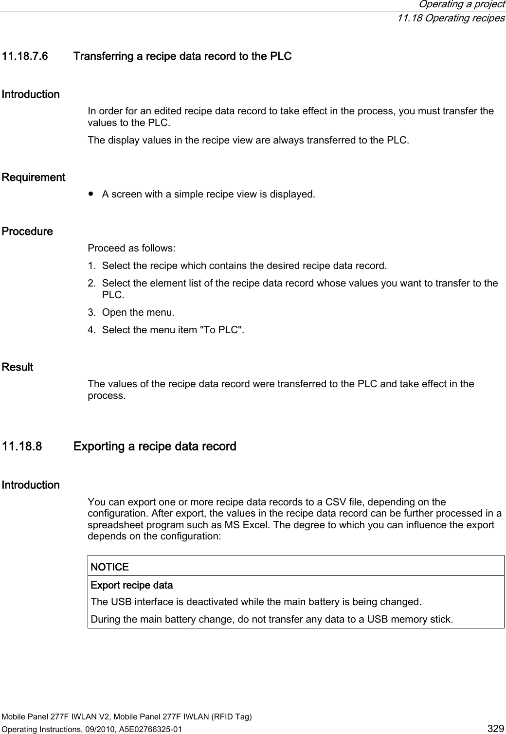
![Operating a project 11.11 Operating the slider control Mobile Panel 277F IWLAN V2, Mobile Panel 277F IWLAN (RFID Tag) 294 Operating Instructions, 09/2010, A5E02766325-01 The layout of the gauge depends on the configuration: ● A trailing pointer can display the maximum value reached so far on the scale. The trailing pointer is reset when the screen is reloaded ● The label on the scale can show the measured variable, for example boiler pressure and the physical unit, for example bar 11.11 Operating the slider control The slider control can be used to monitor and change process values within a defined range. The slider control can also be configured without a slider. In this case, you cannot enter a value. The slider control is then only used for displaying values. 6FKLHEHU]XU:HUWHLQJDEH:HUWDQ]HLJHPLWDNWXHOOHP:HUW The layout of the slider control depends on the configuration: ● The slider control can contain a label and a setting range ● The current value can be displayed in the value display below the area of the slider control Procedure Proceed as follows: 1. Touch the slider. 2. Move the slider to the required value. If the value display was configured, you can verify the entered value. 3. Release the slider. The set value is applied. REVIEW ENGLISH 27.07.2010](https://usermanual.wiki/Siemens/277IWLAN-V211.User-Manual-III/User-Guide-1378103-Page-45.png)
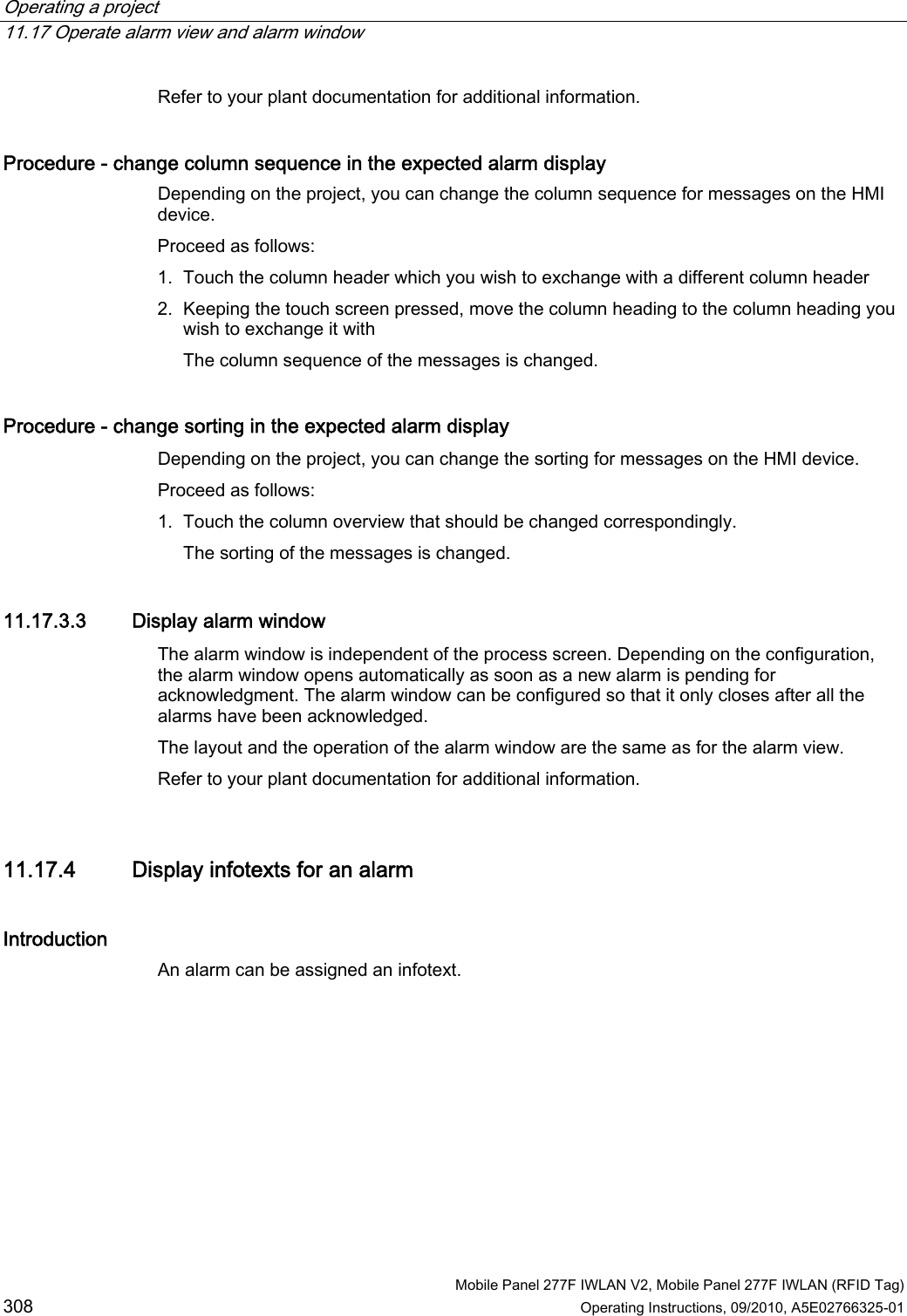
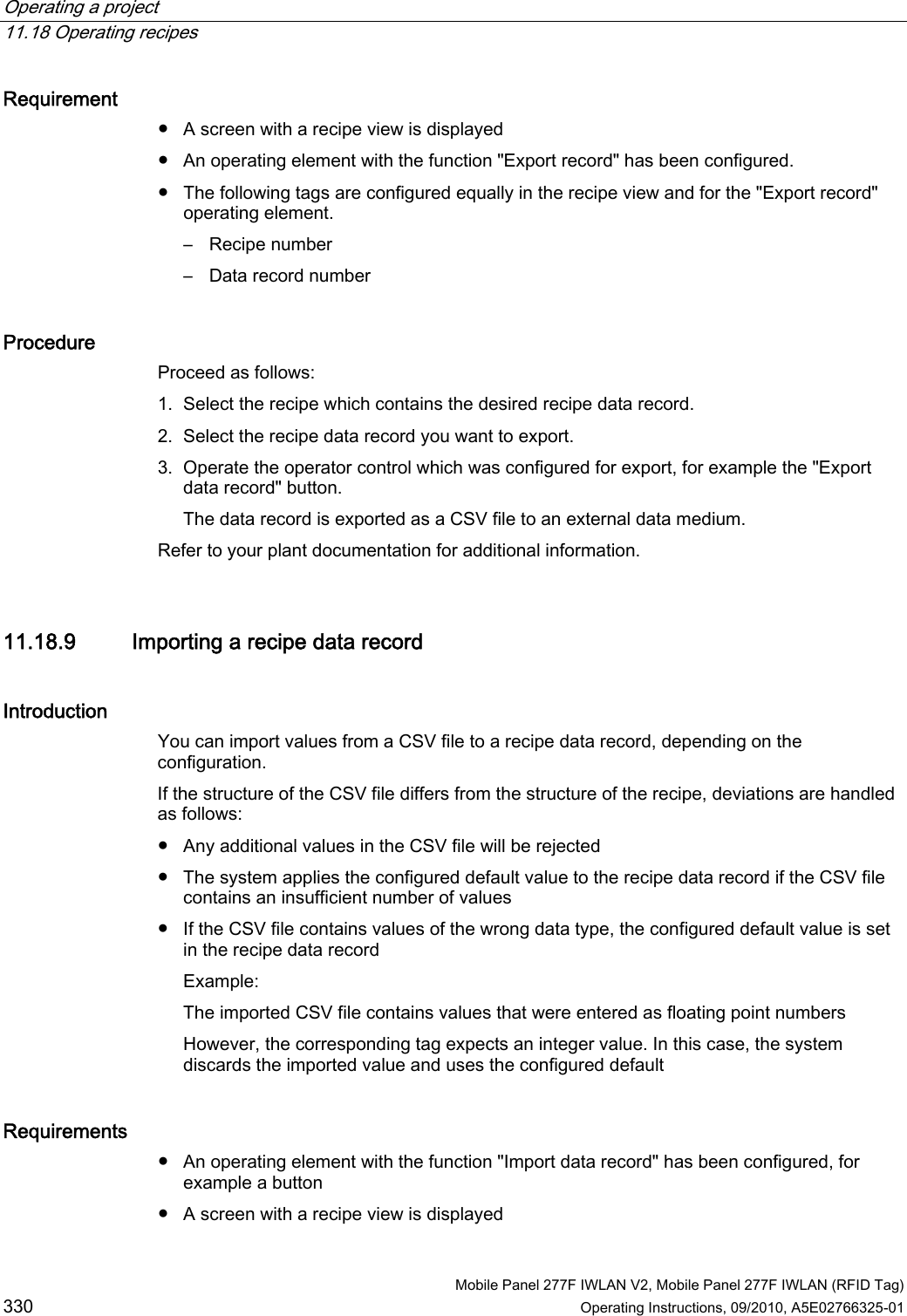
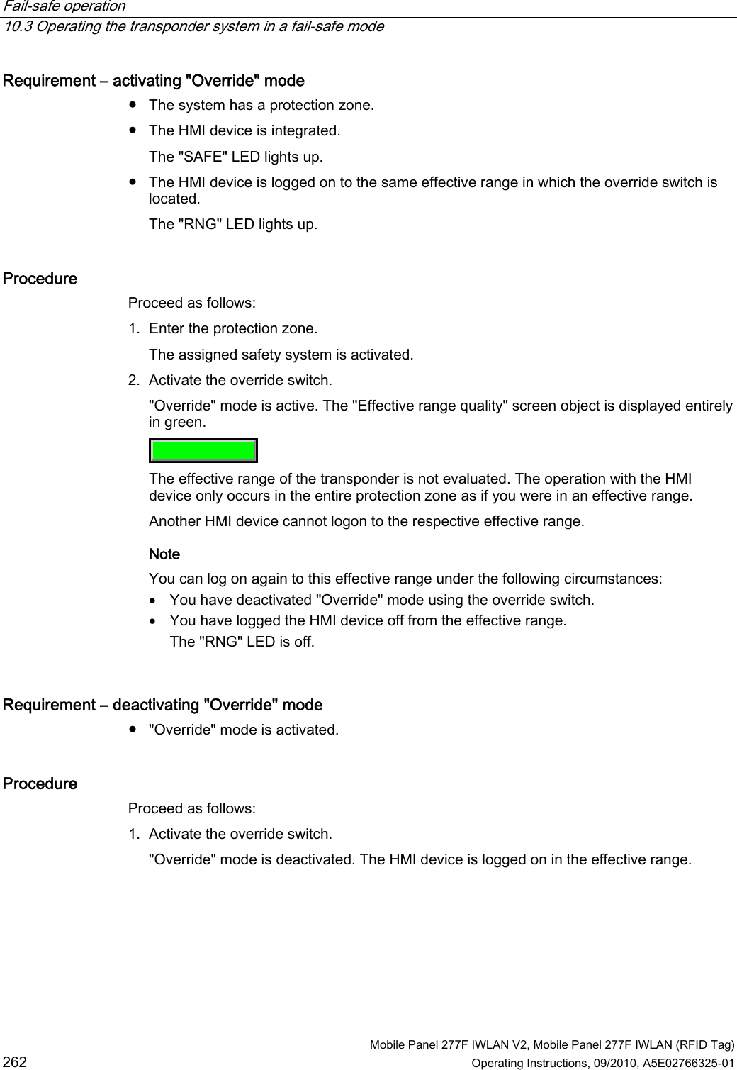
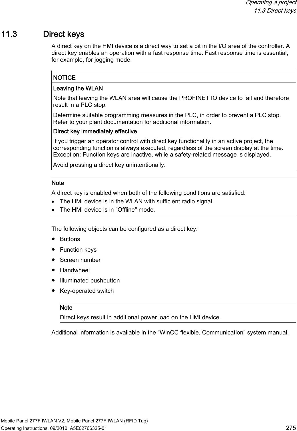
![Operating a project 11.18 Operating recipes Mobile Panel 277F IWLAN V2, Mobile Panel 277F IWLAN (RFID Tag) 332 Operating Instructions, 09/2010, A5E02766325-01 The following figure shows the data flow schematically. 5H]HSWXU5H]HSWXU5H]HSWXU5H]HSWXUQ5H]HSWXUVSHLFKHU%HGLHQJHU¦W6WHXHUXQJ5H]HSWXUDQ]HLJH5H]HSWXUELOG5H]HSWXUYDULDEOH ① Display recipe data record ② Save recipe data record ③ Tags are synchronized ④ Display and edit recipe tags in the recipe screen ⑤ Tags are offline 11.18.10.2 Manual production sequence Introduction You request the production data of different workpieces from the PLC and display this data on the screen of the HMI device for inspection. You want to correct the transferred production data in the recipe view or the recipe screen if necessary. Procedure A scanner connected to the PLC reads the barcode of a workpiece. The barcode names correspond to the names in the recipe data record. Based on the barcode name, the PLC can read the required recipe data record. The recipe data record is displayed for inspection on the HMI device. You can now edit and save the recipe data record. Then transfer the edited recipe data record to the PLC again. REVIEW ENGLISH 27.07.2010](https://usermanual.wiki/Siemens/277IWLAN-V211.User-Manual-III/User-Guide-1378103-Page-83.png)