Siemens ITP1000 Industrial Tablet User Manual SIMATIC ITP1000
Siemens AG Industrial Tablet SIMATIC ITP1000
UserManual.wiki
>
Siemens
>
ITP1000 User Manual
>
UserManual
Contents
1.
UserManual
2.
UserManual_regulatoryNotices
UserManual
Navigation menu
Upload a User Manual
Namespaces
Wiki Guide
HTML
PDF
Info
Views
User Manual
Discussion / Help
Navigation

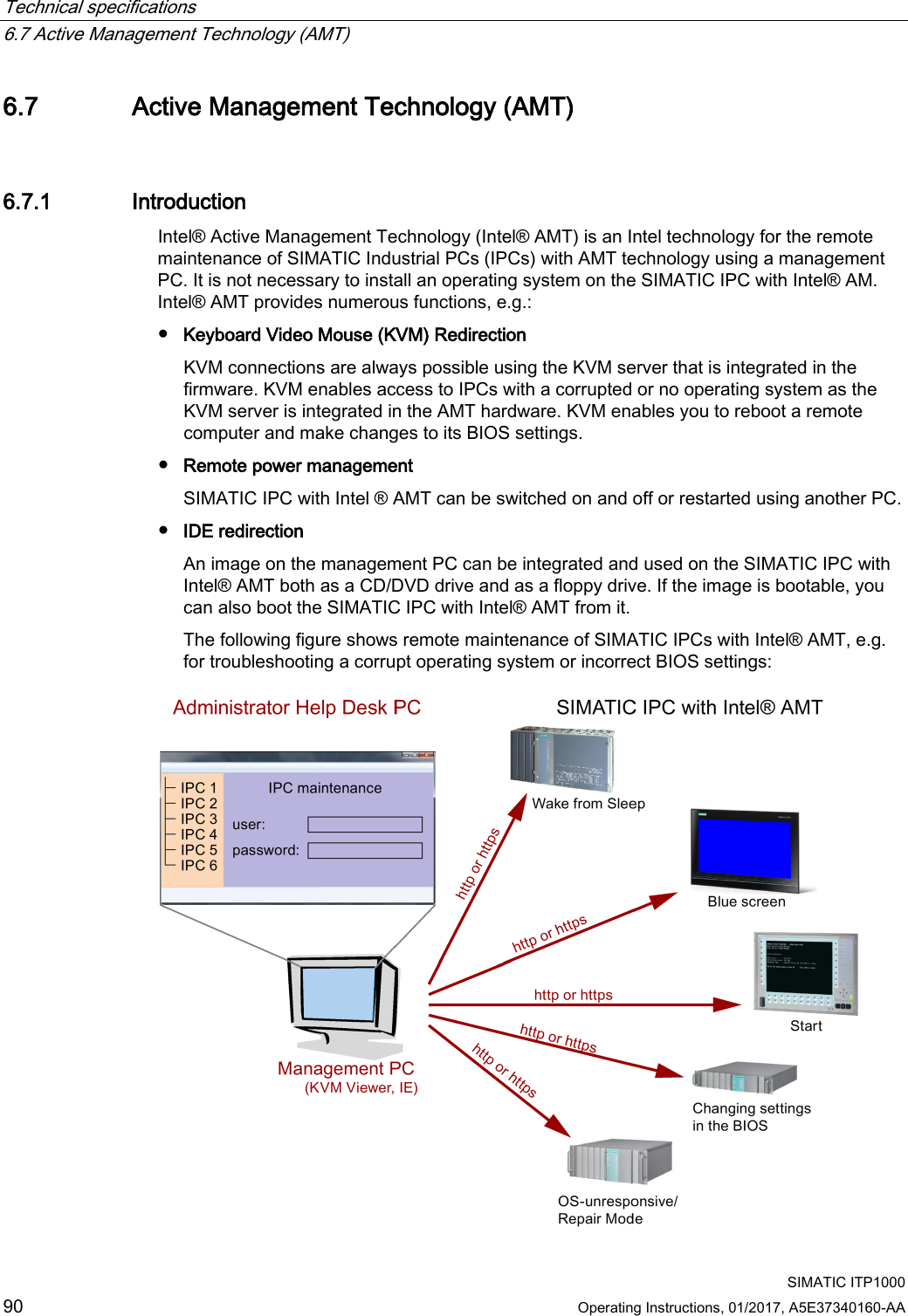
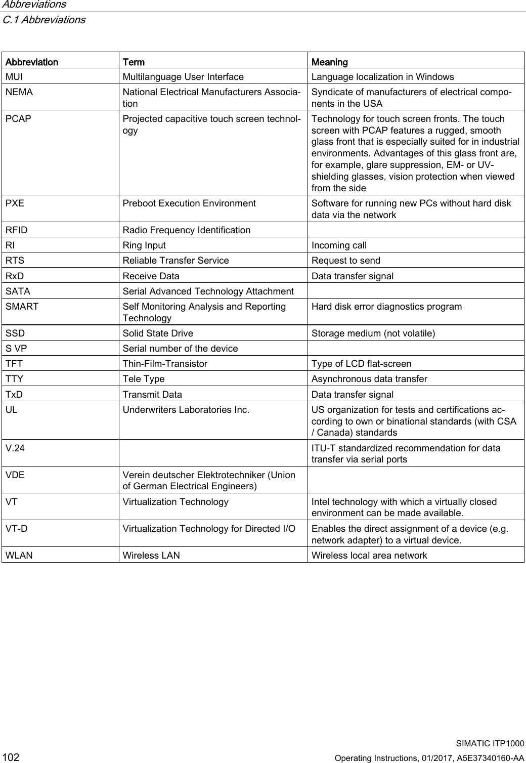
![Technical specifications 6.6 BIOS description SIMATIC ITP1000 84 Operating Instructions, 01/2017, A5E37340160-AA Advanced > SATA Configuration System parameters Defaults Custom entries Serial ATA Port 0 [Micron_M600_MTFDDAV128MBF] (example) Advanced > System Agent (SA) Configuration System parameters Defaults Custom entries SA PCIe Code Version 1.9.0.0 (Example) VT-d Enabled Advanced > Active Management Technology Support System parameters Defaults Custom entries Intel AMT Support Disabled Intel AMT Setup Prompt Enabled MEBx Selection Screen Disabled Un-Configure ME Disabled Intel AMT Configuration Screens Enabled USB Configure Disabled Intel AMT Password Write Enabled USB Configure Disabled PET Progress Enabled Intel AMT SPI Protected Disabled Advanced > CPU Control System parameters Defaults Custom entries SW Guard Extensions (SGX) Software Controlled Select Owner EPOCH input type No change in Owner EPOCHs Intel (VMX) Virtualization Tech-nology Enabled Active Processor Cores All Hyper-Threading Enabled AES Enabled Intel® SpeedStep™ Enabled Intel® Speed Shift Technology Enabled Turbo Mode Enabled C state Enabled](https://usermanual.wiki/Siemens/ITP1000.UserManual/User-Guide-3328708-Page-84.png)
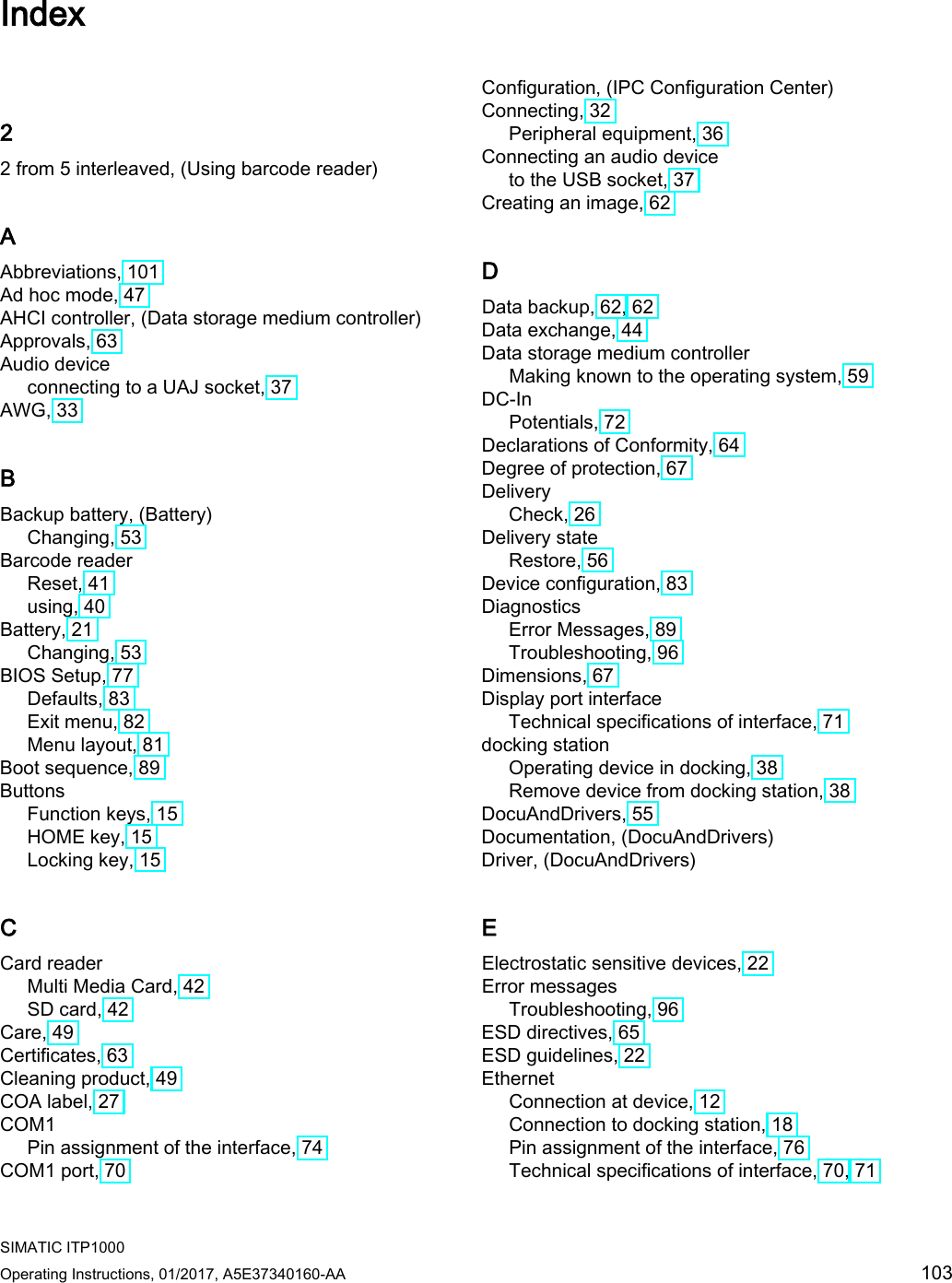
![Technical specifications 6.6 BIOS description SIMATIC ITP1000 Operating Instructions, 01/2017, A5E37340160-AA 85 Security System parameters Defaults Custom entries TPM Operation No Operation Supervisor Password Not Installed User Password Not Installed Power > CPU Configuration System parameters Defaults Custom entries SW Guard Extensions (SGX) Software Controlled Select Owner EPOCH input type No Change in Owner EPOCHs Intel (VMX) Virtualization Tech-nology Enabled Active Processor Cores All Hyper-Threading Enabled AES Enabled Power > Power & Performance > CPU - Power Management Control System parameters Defaults Custom entries Intel (R) SpeedStep (tm) Enabled Intel (R) Speed Shift Technology Disabled Boot System parameters Defaults Custom entries Boot Type Dual Boot Type Quick Boot Enabled Quiet Boot Enabled PXE Boot / Network Stack Disabled PXE Boot capability Disabled Add Boot Options Auto USB Boot Enabled EFI Device First Enabled Timeout [0] Boot > Boot Device Priority System parameters Defaults Custom entries Normal Boot Menue Normal](https://usermanual.wiki/Siemens/ITP1000.UserManual/User-Guide-3328708-Page-85.png)