Siemens MD740-1 GSM/GPRS Modem User Manual Manual
Siemens AG GSM/GPRS Modem Manual
UserManual.wiki
>
Siemens
>
MD740 1 User Manual
Manual
Navigation menu
Upload a User Manual
Namespaces
Wiki Guide
HTML
PDF
Info
Views
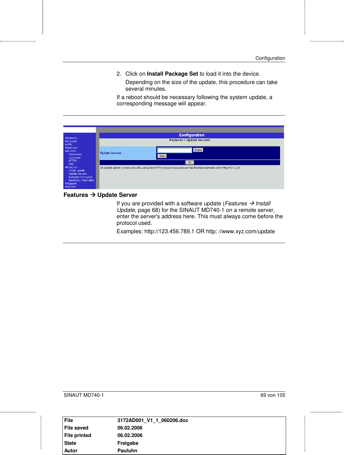
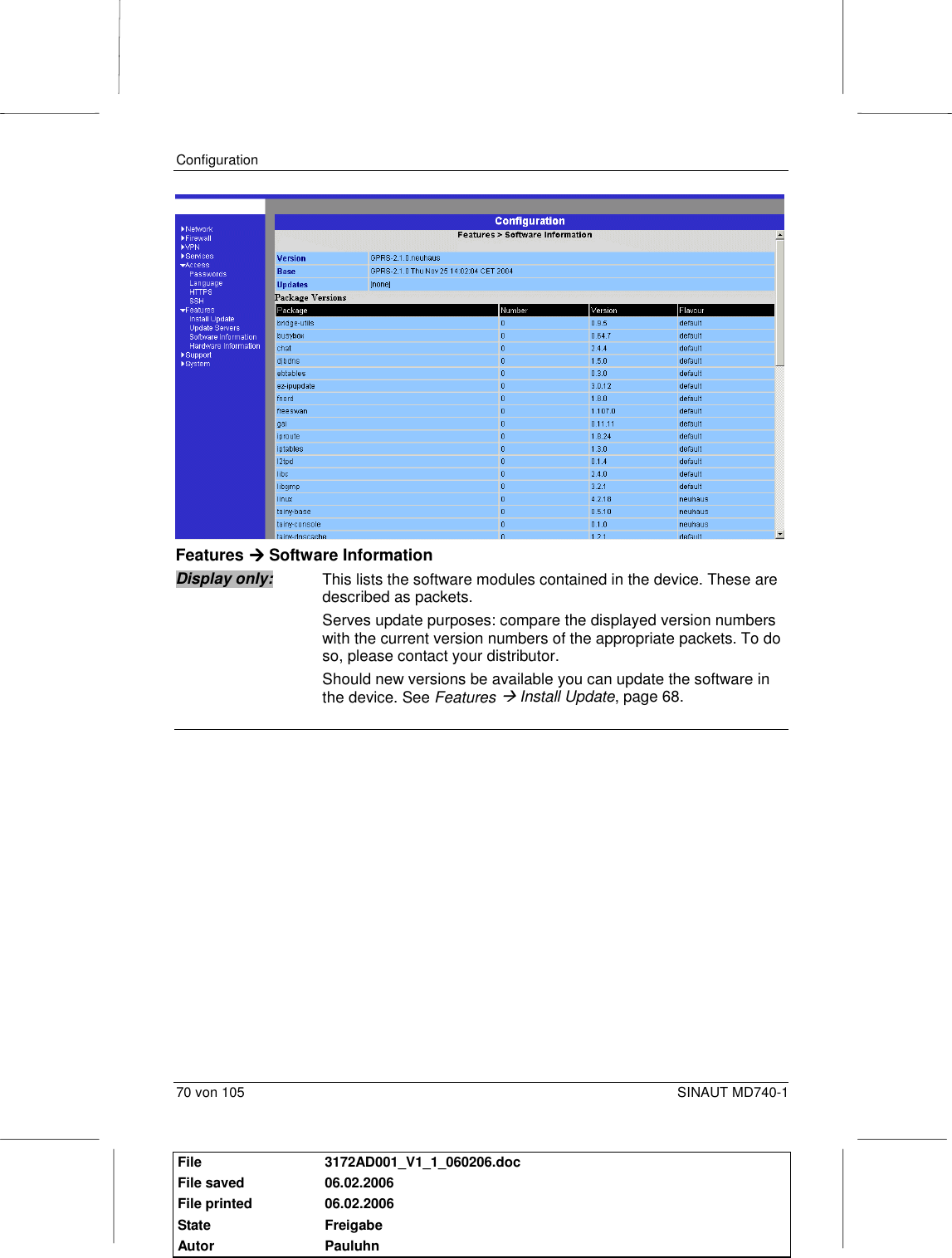
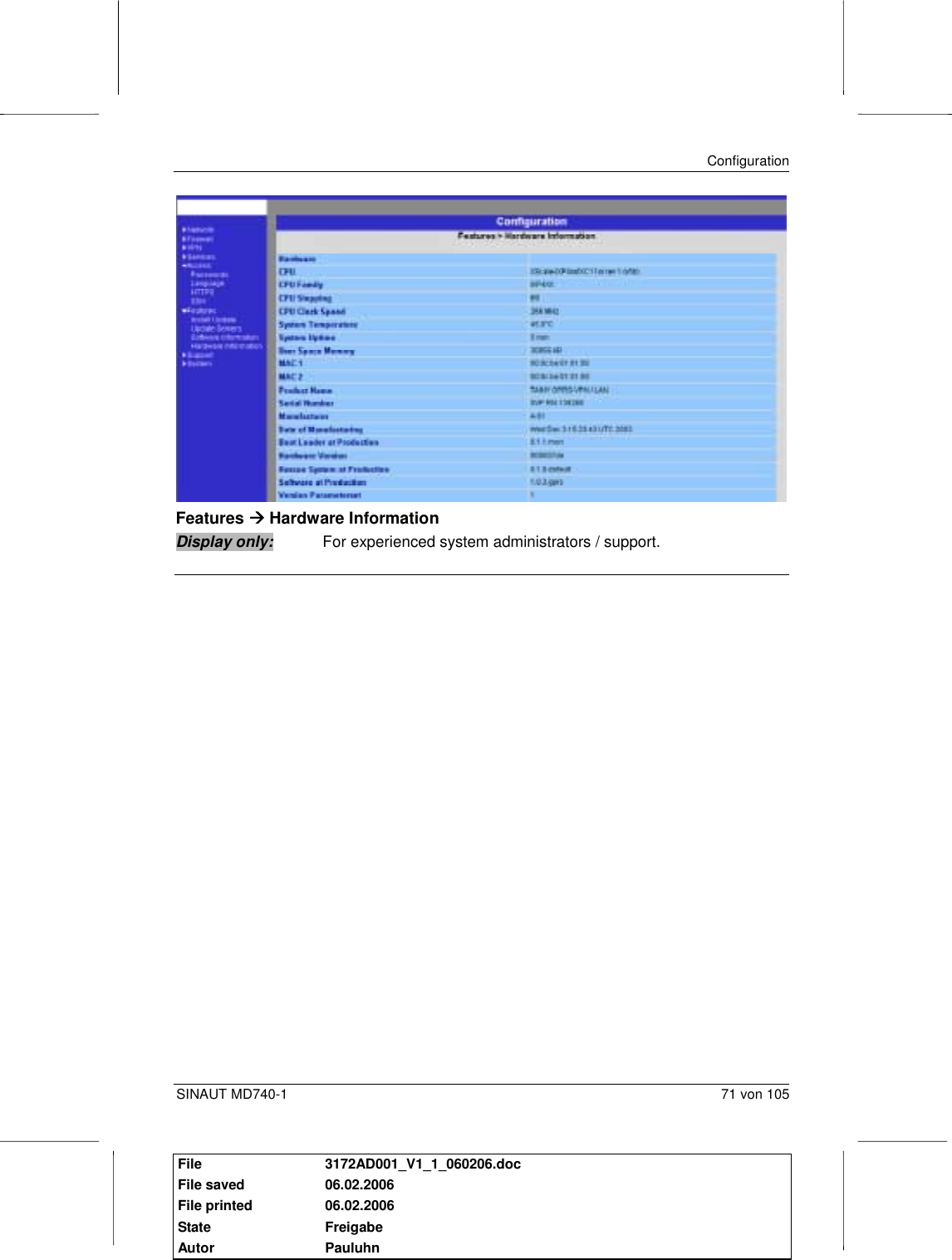
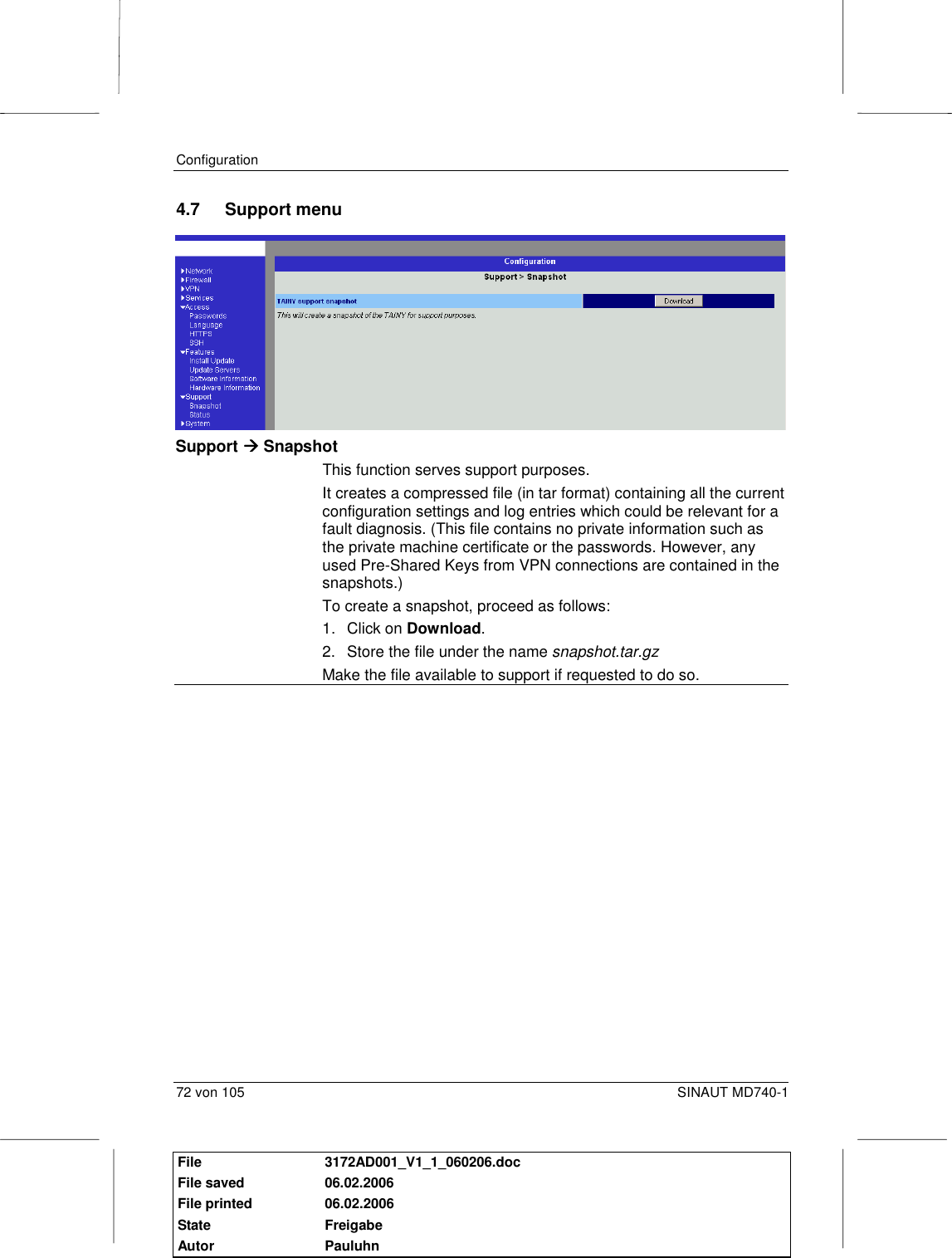
User Manual
Discussion / Help
Navigation