Siemens MD741-1 EGPRS/GSM Router User Manual 3173AD021 09 SIE EN
Siemens AG EGPRS/GSM Router 3173AD021 09 SIE EN
Siemens >
Contents
- 1. UserMan1 MC75
- 2. UserMan2 MC75
- 3. UserMan
UserMan
SIMATIC NET
EGPRS/GPRS-Router
SINAUT MD741-1
System manual
Preface, Contents
Applications and functions 1
Setup 2
Configuration 3
Local interface 4
External interface 5
Security functions 6
Remote access 7
Status, log and diagnosis 8
Additional functions 9
Technical Data 10
Applied Standards and
Approvals 11
Glossary
C79000-G8976-C212
Release 4/2008
SINAUT MD741-1
2 C79000- G8976-C212
Safety Guidelines
This manual contains notices you have to observe in order to ensure your personal safety, as well as to prevent
damage to property. The notices referring to your personal safety are highlighted in the manual by a safety alert
symbol, notices referring only to property damage have no safety alert symbol. These notices shown below are
graded according to the degree of danger.
!
Danger
indicates that death or severe personal injury will result if proper precautions are not taken
!
Warning
indicates that death or severe personal injury may result if proper precautions are not taken.
!
Caution
with a safety alert symbol, indicates that minor personal injury can result if proper precautions are not taken..
Caution
without a safety alert symbol, indicates that property damage can result if proper precautions are not taken.
Notice
indicates that an unintended result or situation can occur if the corresponding information is not taken into
account.
If more than one degree of danger is present, the warning notice representing the highest degree of danger will
be used. A notice warning of injury to persons with a safety alert symbol may also include a warning relating to
property damage.
Qualified Personnel
The device/system may only be set up and used in conjunction with this documentation. Commissioning and
operation of a device/system may only be performed by qualified personnel. Within the context of the safety notes
in this documentation qualified persons are defined as persons who are authorized to commission, ground and
label devices, systems and circuits in accordance with established safety practices and standards.
Prescribed Usage
Note the following:
!
Warning
This device may only be used for the applications described in the catalog or the technical description and only in
connection with devices or components from other manufacturers which have been approved or recommended by
Siemens. Correct, reliable operation of the product requires proper transport, storage, positioning and assembly
as well as careful operation and maintenance
Trademarks
All names identified by ® are registered trademarks of the Siemens AG. The remaining trademarks in this
publication may be trademarks whose use by third parties for their own purposes could violate the rights of the
owner.
Disclaimer of Liability
We have reviewed the contents of this publication to ensure consistency with the hardware and software
described. Since variance cannot be precluded entirely, we cannot guarantee full consistency. However, the
information in this publication is reviewed regularly and any necessary corrections are included in subsequent
editions.
Siemens AG
Automation and Drives
Postfach 48 48
90437 NÜRNBERG
GERMANY
Order No.: C79000-G8976-C212
Release 04/2008
Copyright © Siemens AG 2008
Technical data subject to change

SINAUT MD741-1
C79000- G8976-C212 3
General
The product MD741-1 complies with European standard EN60950, 05.2003, Safety
of Information Technology Equipment.
Read the installation instructions carefully before using the device.
Keep the device away from children, especially small children.
The device must not be installed or operated outdoors or at damp locations.
Do not operate the device if the connecting leads or the device itself are damaged.
External power supply
Use only an external power supply which also complies with EN60950. The output
voltage of the external power supply must not exceed 30V DC. The output of the
external power supply must be short-circuit proof.
! Warning
The power supply unit to supply the SINAUT MD741-1 must comply with the
requirements for a Limited Power Source according to IEC/EN 60950-1
The power supply unit to supply the SINAUT MD741-1 must comply with NEC Class 2
circuits as outlined in the National Electrical Code ® (ANSI/NFPA 70) only.
Please pay regard to section 2.6 of the system manual, as well as the installation
and utilisation regulations of the respective manufacturers of the power supply, the
battery or the accumulator.
SIM card
To install the SIM card the device must be opened. Before opening the device,
disconnect it from the supply voltage. Static charges can damage the device when
it is open. Discharge the electric static of your body before opening the device. To
do so, touch an earthed surface, e.g. the metal casing of the switch cabinet. Please
pay regard to section 2.6 of this system manual.
Handling cables
Never pull a cable connector out of a socket by its cable, but pull on the connector
itself. Cable connectors with screw fasteners (D-Sub) must always be screwed on
tightly. Do not lay the cable over sharp corners and edges without edge protection.
If necessary, provide sufficient strain relief for the cables.
For safety reasons, make sure that the bending radius of the cables is observed.
SINAUT MD741-1
4 C79000- G8976-C212
Failure to observe the bending radius of the antenna cable results in the
deterioration of the system's transmission and reception properties. The minimum
bending radius static must not fall below 5 times the cable diameter and dynamic
below 15 times the cable diameter.
Radio device
! Warning
Never use the device in places where the operation of radio devices is prohibited. The
device contains a radio transmitter which could in certain circumstances impair the
functionality of electronic medical devices such as hearing aids or pacemakers. You
can obtain advice from your physician or the manufacturer of such devices. To prevent
data carriers from being demagnetised, do not keep disks, credit cards or other
magnetic data carriers near the device.
Installing antennas
! Warning
The emission limits as recommended by the German Commission on Radiological
Protection (13/14 September 2001; www.ssk.de) must be observed.
Installing an external antenna
Caution
When installing an antenna outdoors it is essential that the antenna is fitted correctly
by a qualified person.
When the antenna is installed outdoors it must be earthed for lightning protection. The
outdoor antennas shield must be reliable connective to protective earth.
The installation shall be done according the national installation codes
For US this is the National Electric Code NFPA 70, article 810.
For Germany, observe the current version of the Lightning Protection Standard VDE
0185 (DIN EN 62305) Sections 1 to 4 for buildings with lightning protection, or the
standard VDE 0855 (DIN EN 60728-11) in case there is no lightning protection.
This work must be carried out by qualified personnel only.

SINAUT MD741-1
C79000- G8976-C212 5
Requirements for compliance to Safety, Telecom, EMC and other standards
Caution
Observe the regulations listed in chapter 12 before putting the SINAUT MD741-1 into
operation.
Operating costs
Caution: GPRS costs
Note that data packets exchanged for setting up connections, reconnecting, connect
attempts (e.g. Server switched off, wrong destination address, etc.) as well as keeping
the connection alive are also subject to charge.
SINAUT MD741-1
6 C79000- G8976-C212
Firmware with Open Source GPL/LGPL
The firmware of the SINAUT MD741-1 includes open Source Software under terms
of GPL/LGPL. According to section 3b of GPL and of section 6b of LGPL we
provide you the source code. Please write to
s_opsource@gmx.net
s_opsource@gmx.de
Please enter 'Open Source MD741' as subject of your e-mail, that we can filter your
e-mail easier.
Firmware with OpenBSD
The firmware of SINAUT MD741-1 contains sections from the OpenBSD software.
The use of OpenBSD software is subject to the following copyright notice
* Copyright (c) 1982, 1986, 1990, 1991, 1993
* The Regents of the University of California. All rights reserved.
*
* Redistribution and use in source and binary forms, with or without
* modification, are permitted provided that the following conditions
* are met:
* 1. Redistributions of source code must retain the above copyright
* notice, this list of conditions and the following disclaimer.
* 2. Redistributions in binary form must reproduce the above copyright
* notice, this list of conditions and the following disclaimer in the
* documentation and/or other materials provided with the distribution.
* 3. All advertising materials mentioning features or use of this software
* must display the following acknowledgement:
* This product includes software developed by the University of
* California, Berkeley and its contributors.
* 4. Neither the name of the University nor the names of its contributors
* may be used to endorse or promote products derived from this software
* without specific prior written permission.
*
* THIS SOFTWARE IS PROVIDED BY THE REGENTS AND CONTRIBUTORS ``AS IS'' AND
* ANY EXPRESS OR IMPLIED WARRANTIES, INCLUDING, BUT NOT LIMITED TO, THE
* IMPLIED WARRANTIES OF MERCHANTABILITY AND FITNESS FOR A PARTICULAR
* PURPOSE
* ARE DISCLAIMED. IN NO EVENT SHALL THE REGENTS OR CONTRIBUTORS BE LIABLE
* FOR ANY DIRECT, INDIRECT, INCIDENTAL, SPECIAL, EXEMPLARY, OR
* CONSEQUENTIAL
* DAMAGES (INCLUDING, BUT NOT LIMITED TO, PROCUREMENT OF SUBSTITUTE GOODS
* OR SERVICES; LOSS OF USE, DATA, OR PROFITS; OR BUSINESS INTERRUPTION)
* HOWEVER CAUSED AND ON ANY THEORY OF LIABILITY,
* WHETHER IN CONTRACT, STRICT
* LIABILITY, OR TORT (INCLUDING NEGLIGENCE OR OTHERWISE) ARISING IN ANY WAY
* OUT OF THE USE OF THIS SOFTWARE, EVEN IF ADVISED OF THE POSSIBILITY OF
* SUCH DAMAGE.
SINAUT MD741-1
C79000- G8976-C212 7
Preface
Purpose of this documentation
This documentation will support you on your way to successful application of
GSM/GPRS modem SINAUT MD741-1. It will introduce you to the topic in
clear and straightforward steps and provide you with an overview of the
hardware of the SINAUT MD741-1 GSM/GPRS modem. This documentation
will help you during installation and commissioning of SINAUT GSM/GPRS
modem and explains the diagnostics and service options available.
Validity of the documentation
This manual relates to the following product versions
• GPRS/GSM modem MD741-1 hardware release 2.x
SIMATIC Technical Support
You can contact Technical Support for all A&D products
• Phone: +49 (0) 180 5050 222
• Fax: +49 (0) 180 5050 223
You will find further information on our Technical Support on the Web at
http://www.siemens.com/automation/service
Service & Support on the Internet
In addition to our documentation services, you can also make use of all our
knowledge on the Internet:
http://www.siemens.com/automation/service&support
Here, you will find:
• Up-to-date product information (Updates), FAQs (Frequently Asked
Questions), Downloads, Tips and Tricks.
• The Newsletter keeps you constantly up to date with the latest
information on the products you use.
• The Knowledge Manager will find the documents you need.
• In the Forum, users and specialists exchange information and
experience.
• You can find your local contact for Industry Automation in our contacts
database.
• You will find information on local service, repairs, spares and much more
under the rubric "Service".
SINAUT MD741-1
8 C79000- G8976-C212
You will find the latest version of this documentation under the entry ID
22550242.
Do you still have questions relating to the use of the products described in
the manual? If so, then please talk to your local Siemens contact.
You will find the addresses in the following sources:
• On the Internet at: http://www.siemens.com/automation/partner
• On the Internet at http://www.siemens.com/simatic-net specifically for
SIMATIC NET products
• In the catalog CA 01
• In the catalog IK PI specifically for SIMATIC NET products
Statements, certificates and other useful information about SINAUT
MD741-1 are available at:
• http://support.automation.siemens.com/WW/view/de/22811843
SIMATIC training center
To familiarize you with the systems and products, we offer a range of
courses. Please contact your regional training center or the central training
center in
D-90327 Nuernberg.
Phone: +49 (911) 895-3200
http://www.sitrain.com
SIMATIC NET training center
For courses specifically on products from SIMATIC NET, please contact:
SIEMENS AG
Siemens AG, A&D Informations- und Trainings-Center
Dynamostr. 4
D-68165 Mannheim
Phone: +49 (621) 4 56-23 77
Fax: +49 (621) 4 56-32 68
SINAUT MD741-1
C79000- G8976-C212 9
Contents
1 Applications and functions ......................................................................................... 11
2 Setup.............................................................................................................................. 15
2.1 Step by step....................................................................................................... 15
2.2 Preconditions for operation................................................................................ 16
2.3 Device front........................................................................................................ 17
2.4 Service button (SET) ......................................................................................... 17
2.5 Operating state indicators.................................................................................. 18
2.6 Connections....................................................................................................... 19
2.7 Inserting the SIM card........................................................................................ 21
2.8 Top rail mounting ............................................................................................... 22
3 Configuration................................................................................................................ 23
3.1 TCP/IP configuration of the network adapter in Windows XP ........................... 24
3.2 Establishing a configuration connection ............................................................ 25
3.3 Start page of the Web user interface................................................................. 28
3.4 Language selection............................................................................................ 31
3.5 Configuration procedure .................................................................................... 32
3.6 Configuration Profiles ........................................................................................ 33
3.7 Changing the password ..................................................................................... 34
3.8 Reboot ............................................................................................................... 35
3.9 Load factory settings.......................................................................................... 37
4 Local interface .............................................................................................................. 39
4.1 IP addresses of the local interface .................................................................... 39
4.2 DHCP server to local network ........................................................................... 41
4.3 DNS to local network ......................................................................................... 43
4.4 Local hostname ................................................................................................. 45
4.5 System Time/NTP.............................................................................................. 46
4.6 Additional Internal Routes ................................................................................. 48
5 External interface ......................................................................................................... 49
5.1 Access parameters to EGPRS/GPRS ............................................................... 49
5.2 EGPRS/GPRS Connection Monitoring.............................................................. 51
5.3 Hostname via DynDNS...................................................................................... 53
6 Security functions ........................................................................................................ 57
6.1 Packet Filter....................................................................................................... 57
6.2 Port Forwarding ................................................................................................. 62
6.3 Advanced security functions.............................................................................. 64
6.4 Firewall Log ....................................................................................................... 66
7 VPN connection............................................................................................................ 67

Contents
SINAUT MD741-1
10 C79000- G8976-C212
7.1 VPN Roadwarrior Mode..................................................................................... 69
7.2 VPN IPsec Standard Mode................................................................................ 76
7.3 Loading VPN certificates ................................................................................... 85
7.4 Firewall rules for VPN tunnel ............................................................................. 87
7.5 Advanced settings for VPN connections ........................................................... 88
7.6 Status of the VPN connections.......................................................................... 90
8 Remote access ............................................................................................................. 91
8.1 HTTPS remote access....................................................................................... 91
8.2 SSH remote access ........................................................................................... 93
8.3 Remote access via dial-in connection ............................................................... 95
9 Status, log and diagnosis............................................................................................ 99
9.1 System status display ........................................................................................ 99
9.2 Log ................................................................................................................... 103
9.3 Remote logging................................................................................................ 105
9.4 Snapshot.......................................................................................................... 107
9.5 Hardware information ...................................................................................... 109
9.6 Software information........................................................................................ 110
10 Additional functions................................................................................................... 111
10.1 Alarm SMS....................................................................................................... 111
10.2 Software Update .............................................................................................. 112
11 Technical Data ............................................................................................................ 115
12 Applied Standards and Approvals............................................................................ 119
12.1 Equipment........................................................................................................ 119
12.2 EU Declaration of Conformance...................................................................... 119
12.3 Compliance to FM, UL and CSA ..................................................................... 121
12.4 Compliance to FCC ......................................................................................... 122
Glossary ...................................................................................................................... 125
SINAUT MD741-1
C79000- G8976-C212 11
Applications and functions 1
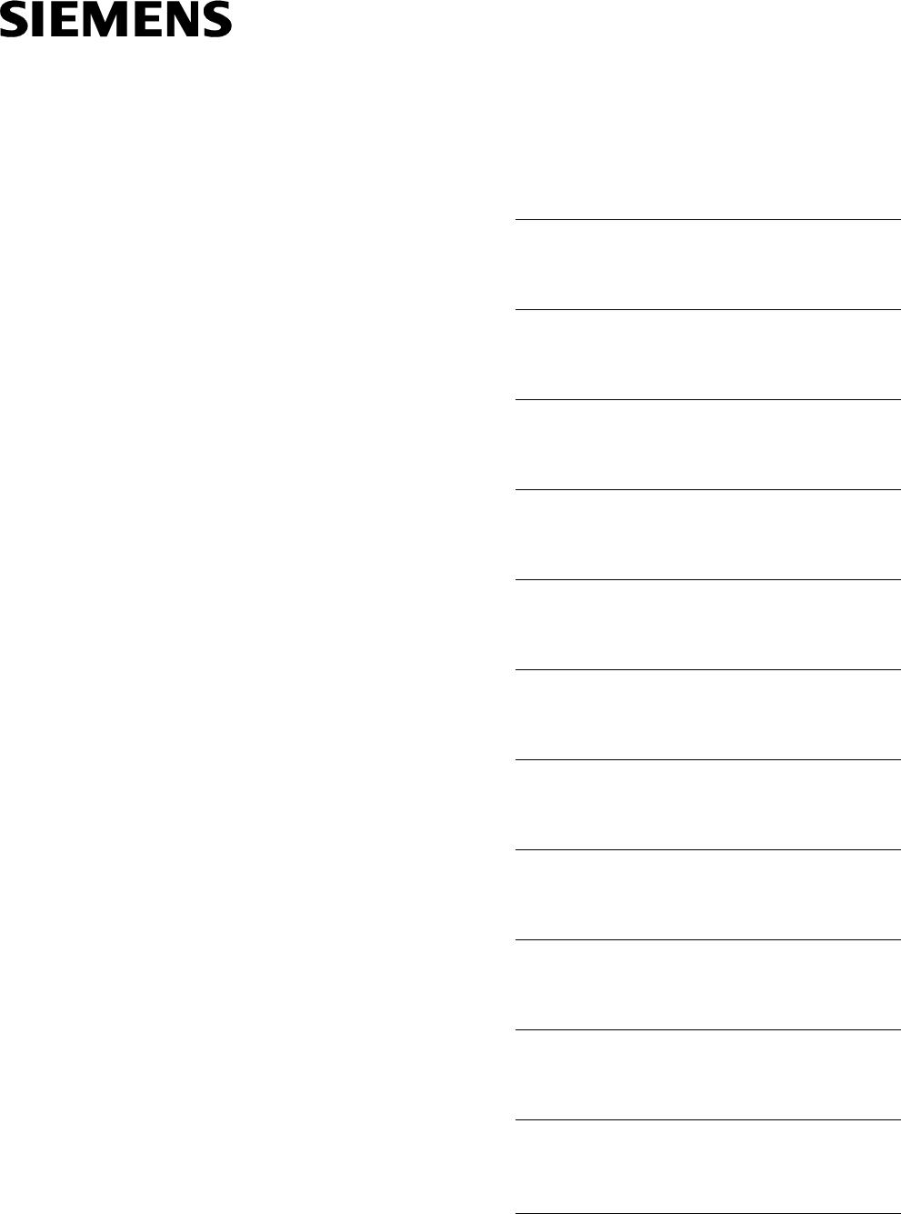
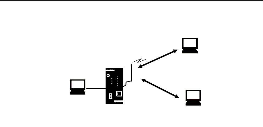
The SINAUT MD741-1 provides a wireless connection to the Internet or to a private
network. The SINAUT MD741-1 can provide this connection in any location where
a GSM network (Global System for Mobile Communication = mobile phone
network) is available which provides the services EGPRS (Enhanced General
Packet Radio Service = EDGE) or GPRS (General Packet Radio Service). A
precondition for this is a SIM card of a GSM network operator with the appropriate
services activated.
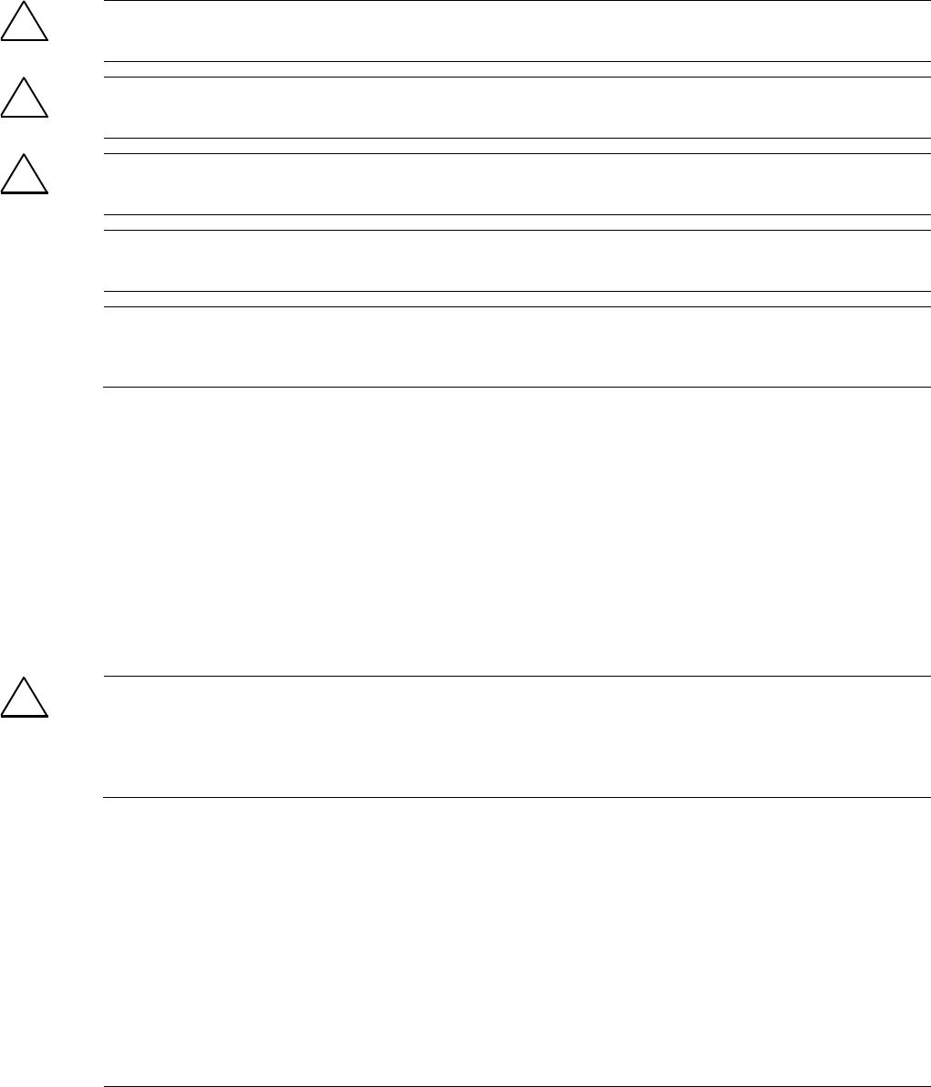
The SINAUT MD741-1 thus links a locally connected application or entire networks
to the Internet via wireless IP connections. It is also possible to connect directly to
an intranet, to which in turn the external remote stations are connected.
The SINAUT MD741-1 can establish a VPN (Virtual Private Network) between a
locally connected application / a network and an external network, and can protect
this connection against access by third parties through the use of IPsec (Internet
Protocol Security).
In order to perform these tasks in the scenarios described, the device combines the
following functions:
• EDGE modem for flexible data communication via EGPRS or GPRS
• Firewall for protection against unauthorized access. The dynamic packet filter
examines data packets based on their source and destination addresses
(stateful inspection firewall) and blocks undesirable data traffic (anti-spoofing)
• The SINAUT MD741-1 can establish via the wireless IP connections a VPN
Virtual Private Network) between the locally connected application or network
and en external network and can protect this connection by IPsec (Internet
Protocol Security) against unwanted access by third parties.
Applications and functions
SINAUT MD741-1
12 C79000- G8976-C212
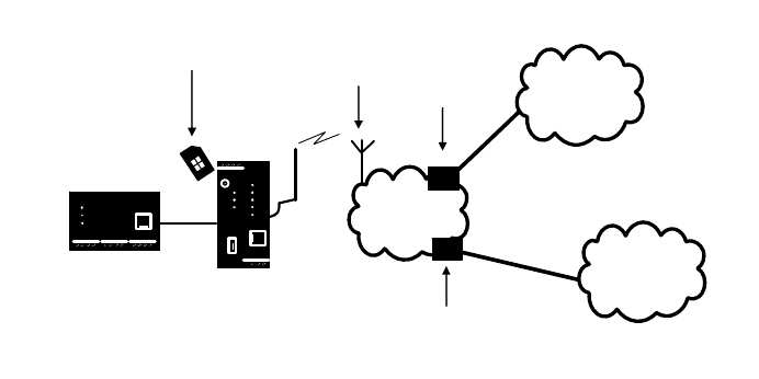
Application examples of the SINAUT MD741-1
APN
(E-)GPRS INTERNET
MD741-1
DSL-Modem
TIM
CPU
VPN-Router
Central
Station
ST7cc
VPN-Tunnel
S7-300
Figure 1-1 Connection between CPU and Central Station
APN
(E-)GPRS INTERNET
MD741-1
DSL-Modem VPN-Router
Central
Station
ST7cc
MD741-1
VPN-Tunnel
VPN-Tunnel
TIM
Logical
connection
TIM
CPU
TIM
CPU
Figure 1-2 Connection between two CPU
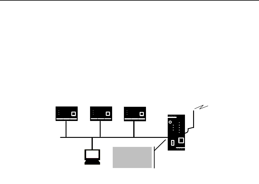
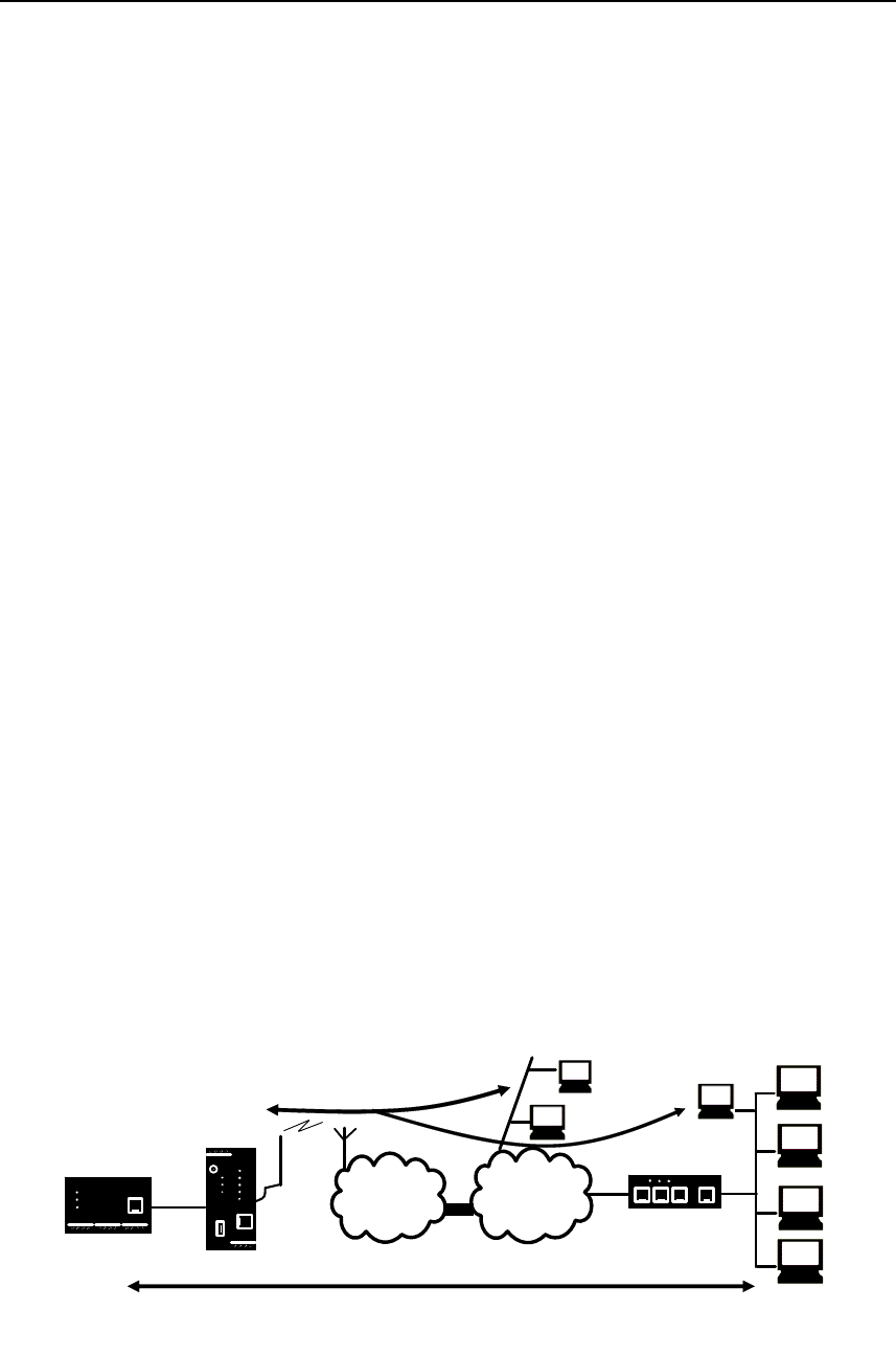
Configuration
The device can be configured via a Web user interface that can simply be
displayed using a Web browser. It can be accessed by means of the following:
• the local interface
• EGPRS/GPRS
• CSD (Circuit Switched Data = dial-in data connection) of the GSM
Applications and functions
SINAUT MD741-1
C79000- G8976-C212 13
MD741-1
Connection
via (E-)GPRS
PC with
Web browser
Connection via
GSM-CSD
PC with
Web browser
PC with
Web browser
Figure 1-3 Configuration
Firewall functions
The SINAUT MD741-1 provides the following firewall functions in order to protect
the local network and itself from external attacks:
● Stateful inspection firewall
● Anti-spoofing
● Port forwarding
● NAT
Additional functions
The SINAUT MD741-1 provides the following additional functions:
● DNS cache
● DHCP server
● NTP
● Remote logging
● In Port
● Web user interface for configuration
● Sending alarm SMS
● SSH console for configuration
● DynDNS client
● Dial-in data connection for maintenance and remote configuration

Applications and functions
SINAUT MD741-1
14 C79000- G8976-C212
SINAUT MD741-1
C79000- G8976-C212 15
Setup 2
2.1 Step by step
Set up the SINAUT MD741-1 in the following steps:
Step Chapter
1.
First familiarise yourself with the preconditions for operation
of the SINAUT MD741-1.
2.2
2.
Read the safety instructions and other instructions at the
beginning of this document very carefully, and be sure to
follow them.
3.
Familiarise yourself with the control elements, connections
and operating state indicators of the SINAUT MD741-1.
2.4 -2.6
4.
Connect a PC with a Web browser (Admin PC) to the local
interface (X2) of the SINAUT MD741-1.
3
5.
Using the Web user interface of the SINAUT MD741-1, enter
the PIN (Personal Identification Number) of the SIM card.
5.1
6.
Disconnect the SINAUT MD741-1 from the power supply. 2.6
7.
Insert the SIM card in the device. 2.7
8.
Connect the antenna. 2.6
9.
Connect the SINAUT MD741-1 to the power supply. 2.6
10.
Set the SINAUT MD741-1 up in accordance with your
requirements.
3 - 10
11.
Connect your local application. 2.6

Setup
SINAUT MD741-1
16 C79000- G8976-C212
2.2 Preconditions for operation
In order to operate the SINAUT MD741-1, the following information must be on
hand and the following preconditions must be fulfilled:
Antenna
An antenna, adapted to the frequency bands of the GSM network operator you
have chosen: 850 MHz, 900 MHz, 1800 MHz or 1900 MHz. Use only antennas
from the accessories for the SINAUT MD741-1.
See Chapter 2.6.
Power supply
A power supply with a voltage between 12 VDC and 30 VDC that can provide
sufficient current.
See Chapter 2.6.
SIM card
A SIM card from the chosen GSM network operator.
PIN
The PIN for the SIM card.
EGPRS / GPRS activation
The SIM card must be activated by your GSM network operator for the services
EGPRS or GPRS.
The EGPRS / GPRS access data must be known:
● Access Point Name (APN)
● User name
● Password
CSD 9600 bit/s activation
The SIM card must be activated by your GSM network operator for the CSD
service if you wish to use remote configuration via a dial-in data connection, see
Chapter 8.3.
Setup
SINAUT MD741-1
C79000- G8976-C212 17
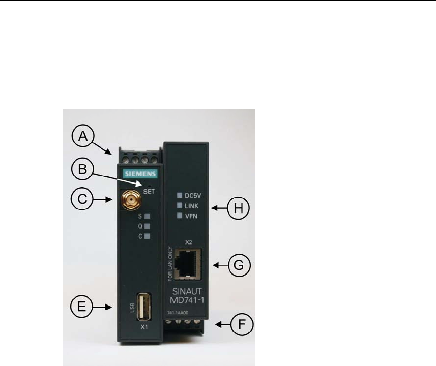
2.3 Device front
Here are definitions of terms frequently used in this manual:
A – Connection terminals for the
power supply
B – Set button
C – Antenna jack type SMA
D – Operating state indicators S,
Q,
E – X1 (Service; USB) – without
function
F –
Connection terminals for the
gate inputs and outputs
G – 10/100 Base-T - RJ45 jack for
connecting the local network
H – Operating state indicators
Power, LAN, VPN
Figure 2-1 Operating elements
2.4 Service button (SET)
On the front side of the SINAUT MD741-1 there is a small hole (see B) which is
SET marked and has a button behind it. Use a pointed object, e.g. a straightened-
out paperclip, to press this button.
● If you press the button for longer than 5 seconds, the SINAUT MD741-1
reboots and loads the factory settings.

Setup
SINAUT MD741-1
18 C79000- G8976-C212
2.5 Operating state indicators
The SINAUT MD741-1 has 7 indicator lamps (LEDs) to indicate the operating state.
The 3 indicator lamps on the left-hand side of the device indicate the state of the
EGPRS wireless modem:
LED State Meaning
Flashing slowly PIN transfer
Flashing quickly PIN error / SIM error
S (Status)
ON PIN transfer successful
OFF Not logged into GSM network
Flashing briefly Poor signal strength
(CSQ < 6)
Flashing slowly Medium signal strength
(CSQ= 6..10)
ON, with brief interruptions Good signal strength
(CSQ=11-18)
Q
(Quality)
ON Very good signal strength
(CSQ > 18)
OFF No connection
Flashing quickly Service call via CSD active
ON with brief interruptions GPRS connection active
C
(Connect)
ON EGPRS connection active
Light up in sequence quickly Booting
Light up in sequence slowly Update
S, Q, C
together
Flashing quickly in unison Error
The 3 indicator lamps on the right-hand side of the device indicate the state of
additional device functions:
LED State Meaning
ON Device switched on, operating
voltage present
DC5V
OFF Device switched off, operating
voltage not present
ON Ethernet connection established to the
local application / the local network
OFF No Ethernet connection to the local
application / the local network
LINK
ON with brief interruptions Data transfer via the Ethernet
connection
ON VPN connection active
VPN
OFF VPN connection active

Setup
SINAUT MD741-1
C79000- G8976-C212 19
2.6 Connections
X2 (10/100 Base-T)
The local network is connected to the local applications at the 10/100 Base-T
connection, e.g. a programmable controller, a machine with an Ethernet interface
for remote monitoring, or a notebook or desktop PC.
To set up the SINAUT MD741-1, connect the Admin PC with Web browser here.
The interface supports autonegation. It is thus detected automatically whether a
transmission speed of 10 Mbit/s or 100 Mbit/s is used on the Ethernet.
A connecting cable with a RJ45 plug must be used. It can be a cross-over cable or
a patch cable.
X1 (USB; Service)
In the SINAUT MD741-1 this interface has no function and is reserved for later
applications. Do not connect any devices here. Doing so could interfere with the
SINAUT MD741-1's operation.
SMA antenna jack
The SINAUT MD741-1 has an antenna jack of the type SMA for connecting the
antenna.
The antenna that is used should have an impedance of about 50 ohms. It must be
matched for GSM 900MHz and DCS 1800MHz or GSM 850 MHz and PCS 1900
MHz, depending on which frequency bands your GSM network operator uses. In
Europe and China GSM 900MHz and DCS 1800MHz are used, in the USA GSM
850 MHz and PCS 1900 MHz are used. Obtain this information from your network
operator.
The match (VSWR) of the antenna must be 1:2.5 or better.
Caution:
Use only antennas from the accessories line for the SINAUT MD741-1. Other
antennas could interfere with product characteristics or even lead to defects.
When installing the antenna, a sufficiently good signal quality must be ensured
(CSQ > 11). Use the indicator lamps of the SINAUT MD741-1 which show the
signal quality. Make sure that there are no large metal objects (e.g. reinforced
concrete) close to the antenna.
Observe the installation and user instructions for the antenna being used.
Setup
SINAUT MD741-1
20 C79000- G8976-C212
Warning:
When the antenna is installed outdoors it must be earthed for lightning protection.
The outdoor antennas shield must be reliable connective to protective earth. The
installation shall be done according the national installation codes (For US this is
the National Electric Code NFPA 70, article 810).
This work must be carried out by qualified personnel only.
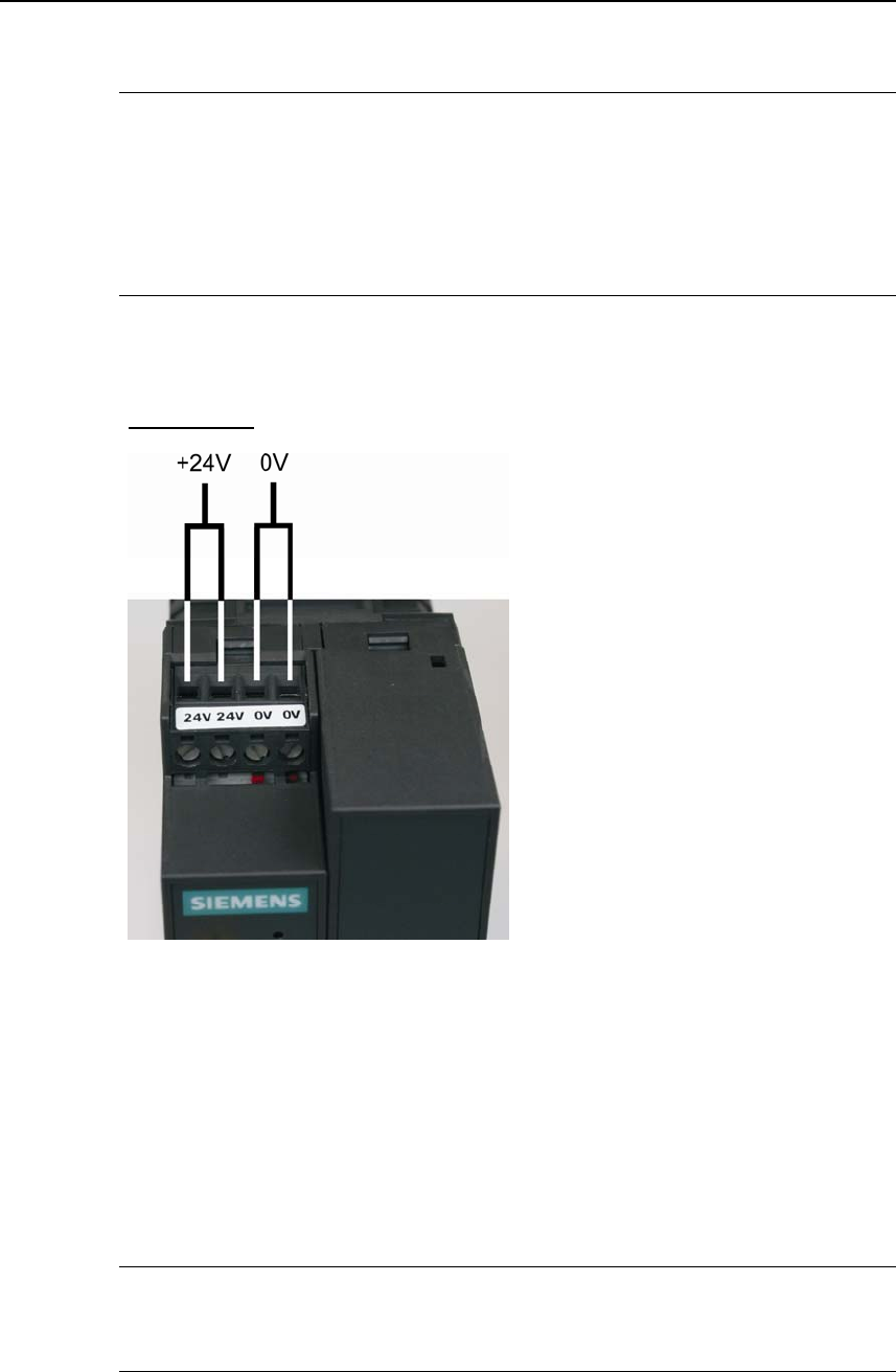
Screw terminals power supply (24V / 0V)
Power supply
Figure 2-2 Screw terminals
The SINAUT MD741-1 operates with direct current of from 12-30 V DC, nominally
24 V DC. This power supply is connected at the screw terminals on the left-hand
side of the device.
Connect the positive supply voltage to one or both screw terminals marked 24V
and the negative supply voltage to one or both screw terminals marked 0V.
The rated current consumption is about 510mA at 12V and 230mA at 30V.
Warning:
The power supply unit of the SINAUT MD741-1 is not galvanic isolated. Observe
the safety instructions at the beginning of this manual.
Setup
SINAUT MD741-1
C79000- G8976-C212 21
Field wiring instruction
Use copper wires only.
Solid wire: 0,5...3mm2 (AWG 20...18)
Strained wire: 0,5...2,5mm2
Torque of screw clamps: 0,6...0,8Nm
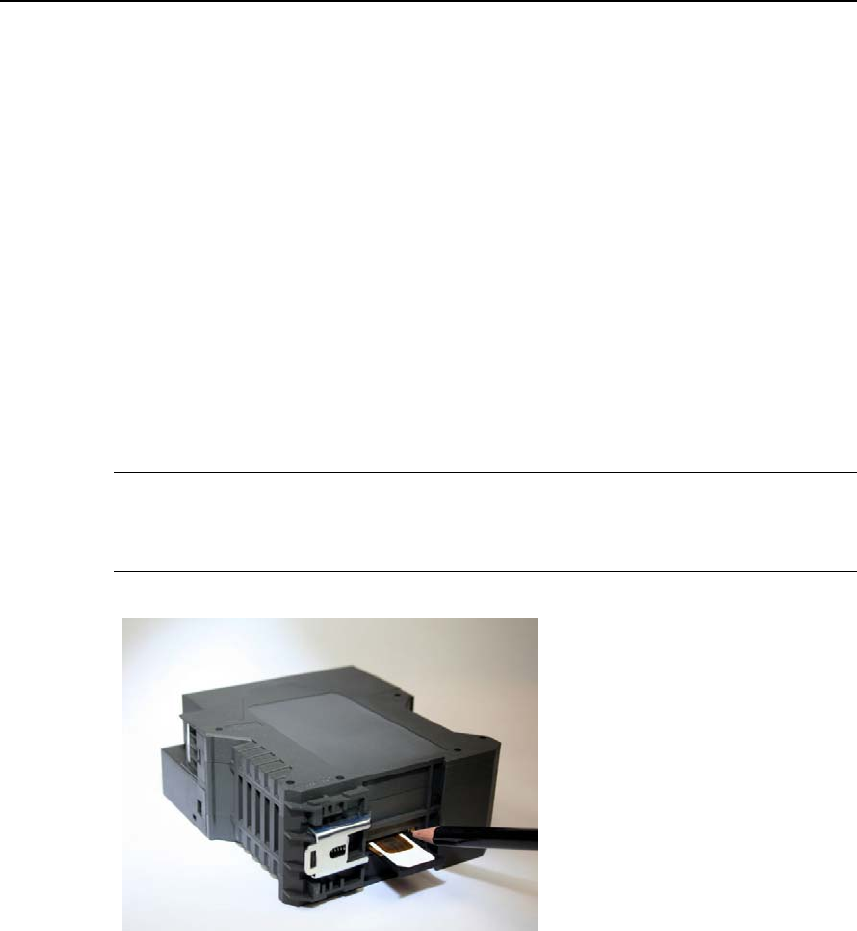
2.7 Inserting the SIM card
Caution:
Before inserting the SIM card, enter the PIN of the SIM card in the SINAUT
MD741-1 via the Web user interface. See Chapter 5.1.
Figure 2-3 Inserting the SIM card
1. After you have entered the PIN of the SIM card, disconnect the SINAUT
MD741-1 completely from the power supply.
2. The drawer for the SIM card is located on the back of the device. Right next to
the drawer for the SIM card in the housing aperture there is a small yellow
button. Press on this button with a pointed object, for example a pencil.
When the button is pressed the SIM card drawer comes out of the housing.
3. Place the SIM card in the drawer so that its gold-plated contacts remain visible.
4. Then push the drawer with the SIM card completely into the housing.
Setup
SINAUT MD741-1
22 C79000- G8976-C212
Caution:
Do not under any circumstances insert or remove the SIM card during operation.
Doing so could damage the SIM card and the SINAUT MD741-1.
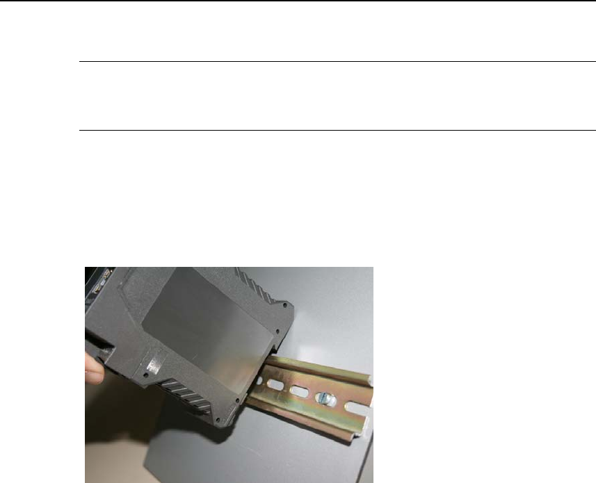
2.8 Top rail mounting
The SINAUT MD741-1 is suitable for top-hat rail mounting on DIN EN 50022 rails.
A corresponding bracket can be found at the rear of the device.
Figure 2-4 Top rail mounting
SINAUT MD741-1
23 C79000- G8976-C212
Configuration 3
Configuration of the router and firewall functions is carried out locally or remotely
via the Web-based administration interface of the SINAUT MD741-1.
Remote configuration
Remote configuration via HTTPS or CSD access is only possible if the SINAUT
MD741-1 is configured for remote access. In this case proceed exactly as
described in Chapter 8.
Configuration via the local interface
The preconditions for configuration via the local interface are:
● The computer (Admin PC) that you use to carry out configuration must be
either connected directly to the Ethernet jack of the SINAUT MD741-1 via a
network cable or it must have direct access to the SINAUT MD741-1 via the
local network.
● The network adapter of the computer (Admin PC) that you use to carry out
configuration must have the following TCP/IP configuration:
IP address: 192.168.1.2
Subnet mask: 255.255.255.0
Instead of the IP address 192.168.1.2 you can also use other IP addresses
from the range 192.169.1.x.
● If you also wish to use the Admin PC to access the external network via the
SINAUT MD741-1, the following additional settings are necessary:
Standard gateway: 192.168.1.1
Preferred DNS server: Address of the domain name server
Configuration
SINAUT MD741-1
24 C79000- G8976-C212
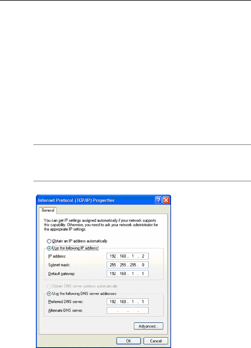
3.1 TCP/IP configuration of the network adapter in Windows
XP
Configure the LAN connection
Click on Start, Connect To ..., Show All Connections…
Then click on LAN Connection. In the dialog box Properties of LAN Connection,
click on the General tab and select there the entry Internet Protocol (TCP/IP). Open
Properties by clicking on the corresponding button.
The window Properties of Internet Protocol (TCP/IP) appears (see illustration
below).
Note:
The path leading to the dialog box Properties of LAN Connection depends on your
Windows settings. If you are not able to find this dialog box, search in the Windows
Help function for LAN Connection or Properties of Internet Protocol (TCP/IP).
Figure 3-1 Properties of Windows Internet Protocol

Configuration
SINAUT MD741-1
C79000- G8976-C212 25
Enter the following values in order to get to the Web user interface of the SINAUT
MD741-1:
IP address: 192.168.1.2
Subnet mask: 255.255.255.0
In addition, enter the following values if you want to use the Admin PC to access
the external network via the SINAUT MD741-1:
Standard gateway: 192.168.1.1
Preferred DNS server: 192.168.1.1
Preferred DNS server
If you call up addresses via a domain name (e.g. www.neuhaus.de), then you must
refer to a domain name server (DNS) to find out what IP address is behind the
name. You can define the following as the domain name server:
● The DNS address of the network operator,
or
● The local IP address of the SINAUT MD741-1, as long as it is configured for
breaking out host names into IP addresses
(see Chapter 4.3; Factory setting).
To define the domain name server in the TCP/IP configuration of your network
adapter, proceed as described above.
3.2 Establishing a configuration connection
Setting up a Web browser
Proceed as follows:
1. Launch a Web browser.
(e.g. MS Internet Explorer Version 7 or later or Mozilla Firefox Version 2 or
later; the Web browser must support SSL (i.e. HTTPS).)
2. Make sure that the browser does not automatically dial a connection when it is
launched.
In MS Internet Explorer, make this setting as follows: Menu Tools, Internet
Options..., tab Connections: Under Dial-up and VPN Settings, make sure that
Never dial a connection is activated.
Configuration
SINAUT MD741-1
26 C79000- G8976-C212
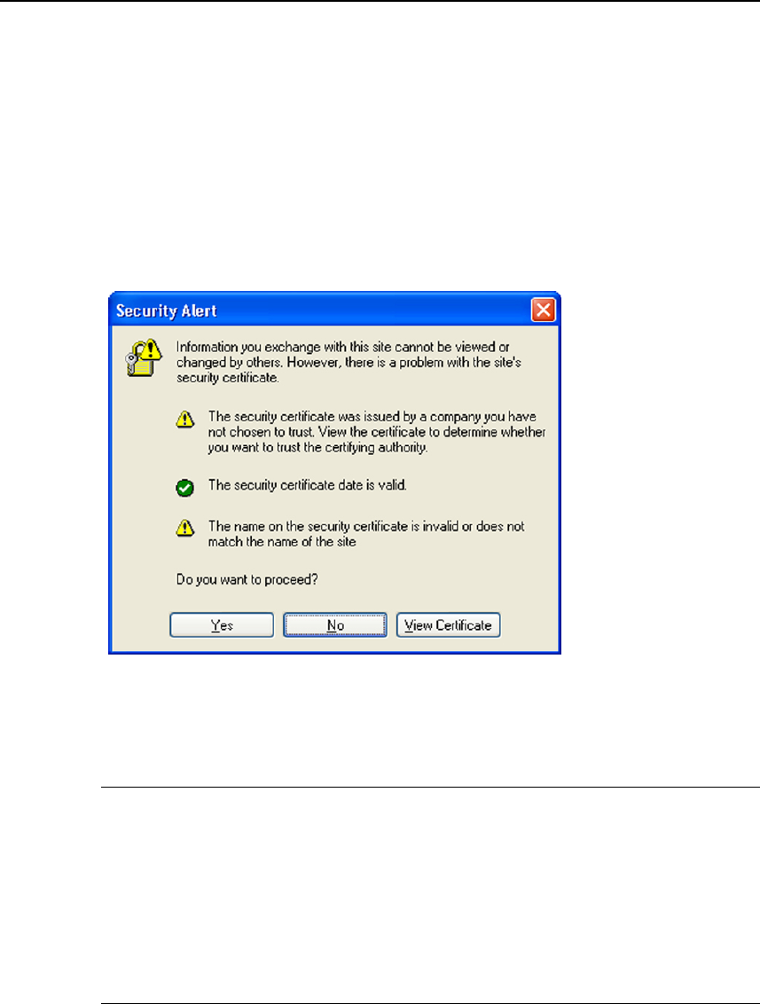
Calling up the start page of the SINAUT MD741-1
3. In the address line of the browser, enter the address of the SINAUT MD741-1
in full. In the factory settings this is:
https://192.168.1.1
Result: A security message appears. In Internet Explorer 7, for example, this
one:
Figure 3-2 Confirming the security message
4. Acknowledge the corresponding safety message with "Continue loading this
page …"
Note
Because the device can only be administered via encrypted access, it is delivered
with a self-signed certificate. In the case of certificates with signatures that the
operating system does not know, a security message is generated. You can
display the certificate.
It must be clear from the certificate that it was issued for SIEMENS AG. The Web
user interface is addressed via an IP address and not using a name, which is why
the name specified in the security certificate, is not the same as the one in the
certificate.
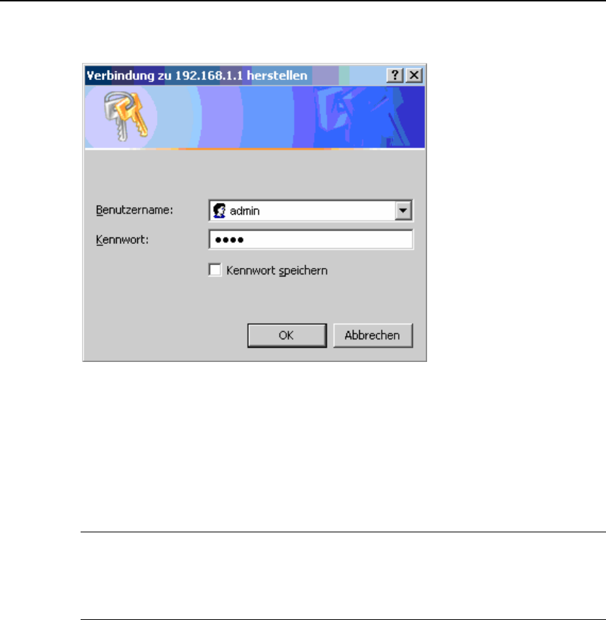
Entering the user name and password
5. You will be asked to enter the user name and the password:
Configuration
SINAUT MD741-1
C79000- G8976-C212 27
Figure 3-3 Enter user name and password
The factory setting is:
User name: admin
Password: sinaut
Note
You should change the password in any event. The factory setting is general
knowledge and does not provide sufficient protection. Chapter 3.7 contains a
description of how to change the password.
The start page is displayed
After the user name and password are entered, the start page of the SINAUT
MD741-1 appears in the Web browser with an overview of the operating state, see
Chapter 3.3.
The start page is not displayed
If after several tries the browser still reports that the page cannot be displayed, try
the following:
● Check the hardware connection. On a Windows computer, go to the DOS
prompt (Menu Start, Programs, Accessories, Command Prompt) and enter the
following command:
ping 192.168.1.1
Configuration
SINAUT MD741-1
28 C79000- G8976-C212
If a return receipt message for the 4 packets that were sent out does not
appear within the specified time period, check the cable, the connections and
the network card.
● Make sure that the browser does not use a proxy server. In MS Internet
Explorer (Version 7.0), make this setting as follows: Menu Tools, Internet
Options..., tab Connections: Under LAN Settings, click on the Settings... button,
then in the dialog box Settings for local network (LAN), make sure that under
Proxy Server the entry Use proxy server for LAN is not activated.
● If other LAN connections are active on the computer, deactivate them for the
duration of the configuration process.
Under the Windows menu Start, Connect To ..., Show All Connections… ,
under LAN or High-Speed Internet right-click on the connection concerned and
select Deactivate in the pop-up menu.
● Enter the address of the SINAUT MD741-1 with a slash:
https://192.168.1.1/
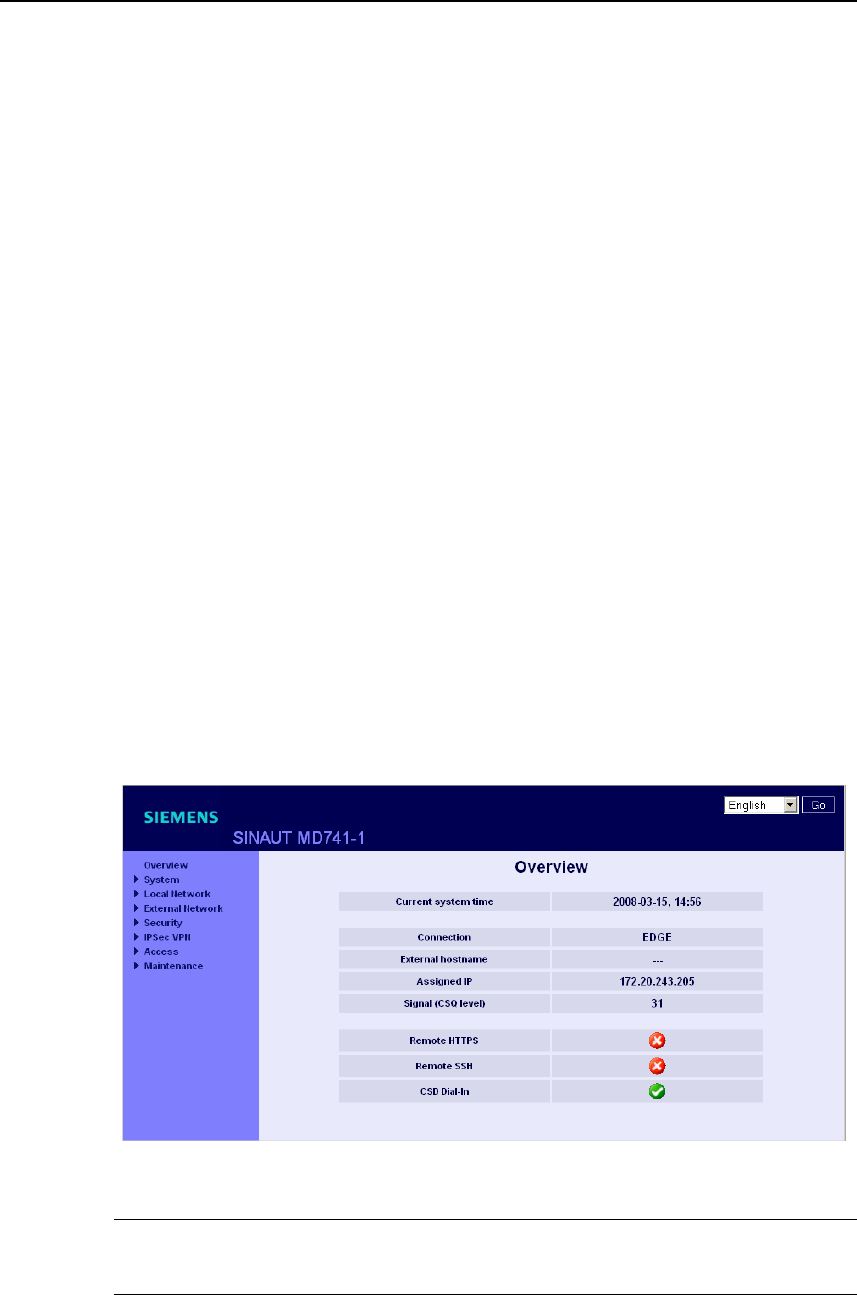
3.3 Start page of the Web user interface
After the Web user interface of the SINAUT MD741-1 is called up and the user
name and password are entered, an overview of the current operating state of the
SINAUT MD741-1 appears.
Figure 3-4 Overview
Note
Use the Refresh function of the Web browser to update the displayed values.

Configuration
SINAUT MD741-1
C79000- G8976-C212 29
Current system time
Shows the current system time of the SINAUT MD741-1 in the format:
Year – Month – Day, Hours – Minutes
Connection
Shows if a wireless connection exists, and which one:
● EDGE connection (IP connection via EGPRS)
● GPRS connection (IP connection via GPRS)
● CSD connection (service connection via CSD)
External hostname
Shows the hostname (e.g. md741.mydns.org) of the SINAUT MD741-1, if a
DynDNS service is being used.
Signal (CSQ level)
Indicates the strength of the GSM signal as a CSQ value.
● CSQ < 6: Poor signal strength
● CSQ= 6..10: Medium signal strength
● CSQ=11-18: Good field strength
● CSQ > 18: Very good field strength
● CSQ = 99: No connection to the GSM network
Assigned IP address
Shoes the IP address at which the SINAUT MD741-1 can be reached in EGPRS or
GPRS. This IP address is assigned to the SINAUT MD741-1 by EGPRS or GPRS.
Note
It may occur that an EDGE (EGPRS) or GPRS connection and an assigned IP
address are both shown, but the connection quality is still not good enough to
transmit data. For this reason we recommend using the active connection
monitoring (see Chapter 5.2).

Configuration
SINAUT MD741-1
30 C79000- G8976-C212
Remote HTTPS
Shows whether remote access to the Web user interface of the SINAUT MD741-1
via EGPRS, GPRS or CSD is permitted (see Chapter 8.1).
● White check mark at green dot: Access is allowed.
● White cross at red dot: Access is not allowed.
Remote SSH
Shows whether remote access to the SSH console of the SINAUT MD741-1 via
EGPRS, GPRS or CSD is permitted (see Chapter 8.2).
● White check mark at green dot: Access is allowed.
● White cross at red dot: Access is not allowed.
CSD Dial-In
Shows whether remote CSD service calls are allowed (see Chapter 8.3).
● White check mark at green dot: Access is allowed.
● White cross at red dot: Access is not allowed.
Configuration
SINAUT MD741-1
C79000- G8976-C212 31
3.4 Language selection
The Web user interface of the SINAUT MD741-1 supports English and German
language.
Figure 3-5 Language selection
Automatic
The SINAUT MD741-1 selects the language of the Web user interface in
accordance to the selected language of the used Web browser:
● German, if the Web browser uses the German language,
● English, in all other cases.
Deutsch
The SINAUT MD741-1 uses the German language, irrespective of the Web
browser setting.
English
The SINAUT MD741-1 uses the English language, irrespective of the Web browser
setting.
Click the GO and refresh your Web browser to change the language.
Configuration
SINAUT MD741-1
32 C79000- G8976-C212
3.5 Configuration procedure
The procedure for configuration is as follows:
Carrying out configuration
1. Use the menu to call up the desired settings
area
2. Make the desired entries on the page
concerned or use Reset to delete the current
entry which has not been saved.
3. Use Save to confirm the entries so that they
are accepted by the device.
Figure 3-6 Configuration
Note
Depending on how you configure the SINAUT MD741-1, you may then have to
adapt the network interface of the locally connected computer or network
accordingly.
When entering IP addresses, always enter the IP address component numbers
without leading zeros, e.g.: 192.168.0.8.
Invalid entries
The SINAUT MD741-1 checks your entries. Obvious errors are detected during
saving and the input box in question is marked.
Figure 3-7 Indication of invalid entries
Configuration
SINAUT MD741-1
C79000- G8976-C212 33
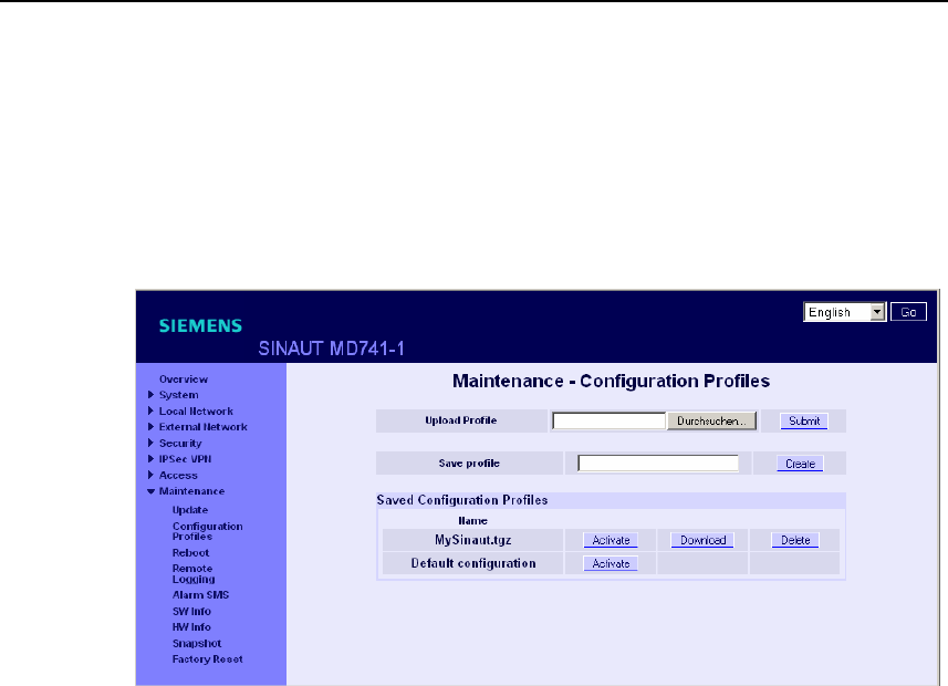
3.6 Configuration Profiles
The settings of the SINAUT MD741-1 can be saved in configuration profiles (files)
and re-loaded at any time.
Figure 3-8 Maintenance > Configurations Profiles
Upload Profile
Loads to the SINAUT MD741-1 a configuration profile that was created before and
saved on the Admin PC. Files with configuration profiles have the file extension
*.epr.
Browse can be used to search the Admin PC for configuration profiles,
Submit loads the configuration profile to the SINAUT MD741-1.
It will then be shown in the table of saved configuration profiles.
Create profile
Saves the current settings of the SINAUT MD741-1 in a configuration profile.
First enter a name for the profile in the input box. Create saves the settings in a
profile with this names and then displays them in the table of saved configuration
profiles.
Saved Configuration Profiles
The table of saved configuration profiles shows all of the profiles that are saved in
the SINAUT MD741-1.
Configuration
SINAUT MD741-1
34 C79000- G8976-C212
Download
Loads the profile to the Admin PC.
Activate
The SINAUT MD741-1 accepts the settings from the selected configuration profile
and continues to work using them.
Delete
The configuration profile is deleted.
The profile Default configuration contains the factory settings, and cannot be
deleted.
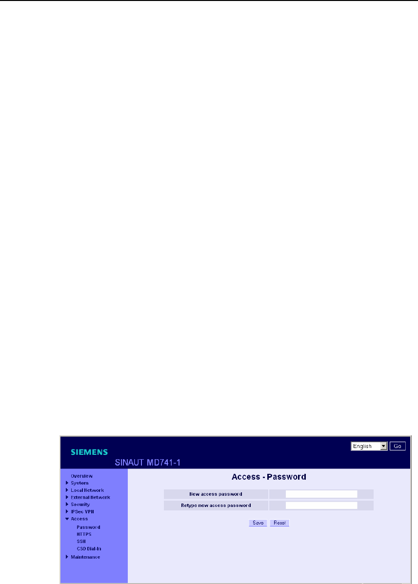
3.7 Changing the password
Access to the SINAUT MD741-1 is protected by an access password. This access
password protects access both via the
● local interface to the Web user interface, and
● via the local interface to the SSH console,
and also access via
● EGPRS or GPRS by https to the Web user interface, and
● EGPRS or GPRS to the SSH console
Figure 3-9 Access > Password

Configuration
SINAUT MD741-1
C79000- G8976-C212 35
Access password (factory setting)
The factory setting for the SINAUT MD741-1 is:
● Password: sinaut
● User name: admin (cannot be changed)
Note
Change the password immediately after initial start-up. The factory setting is
general knowledge and does not provide sufficient protection.
Note
The user name for the SSH access is different from the user name for the Web-
Interface.
User name: root (cannot be changed)
The password for the SSH access is the same as for the Web-Interface.
New access password (with confirmation)
To change the password, enter the new password you have selected in New
access password and confirm the entry in Retype new access password.
Reset can be used to discard any entries that have not yet been saved. Save
accepts the new password.
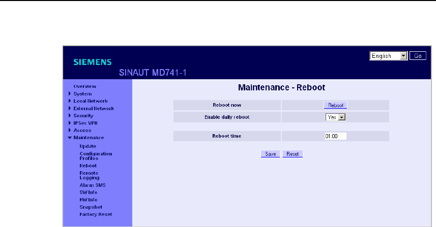
3.8 Reboot
Although the SINAUT MD741-1 is designed for continuous operation, in such a
complex system faults may occur, often triggered by external influences. A reboot
can rectify these faults.
The reboot resets the functions of the SINAUT MD741-1. Current settings
according to the configuration profile do not change. The SINAUT MD741-1
continues to work using these settings after the reboot.
Configuration
SINAUT MD741-1
36 C79000- G8976-C212
Figure 3-10 Maintenance > Reboot
Enable daily reboot
The reboot is carried out automatically once a day if you switch the function on with
Yes.
Specify the Time of the daily reboot. The reboot will be carried out at the specified
system time. Existing connections will be interrupted.
Factory setting
Enable daily reboot: No
Time of the daily reboot: 01:00
Configuration
SINAUT MD741-1
C79000- G8976-C212 37
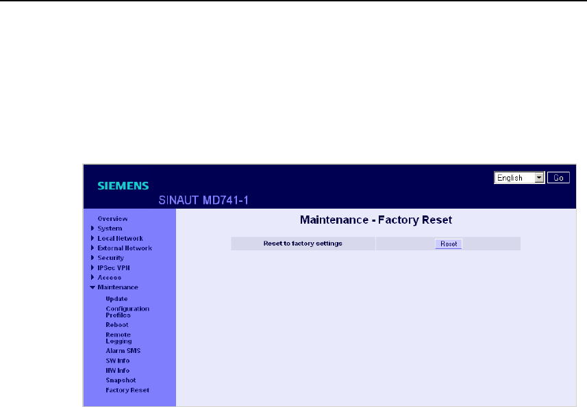
3.9 Load factory settings
The factory settings of the SINAUT MD741-1 can be restored by the following
means:
Figure 3-11 Maintenance > Factory Reset
Reset to factory settings
A click on the push button Reset loads the factory settings, resets the passwords
and deletes the stored certificates, the configuration profiles and the archived log
files.
Service button (SET)
The load of the factory settings can also be activated by pushing the service button
(see chapter 2.4).
Default configuration
If just the factory settings shall be loaded, without to delete the certificates,
configuration profiles and the archived log files, just activate the default
configuration as being described in chapter 3.6.

Configuration
SINAUT MD741-1
38 C79000- G8976-C212
SINAUT MD741-1
39 C79000- G8976-C212
Local interface 4
The local interface is the interface of the SINAUT MD741-1 for connecting the local
network. The interface is labeled X2 on the device. This is an Ethernet interface
with a data rate of 10Mbit/s or 100Mbit/s.
The Local network is the Network connected to the local interface of the SINAUT
MD741-1. The local network contains at least one local application.
Local applications are network components in the local network, for example a
programmable controller, a machine with an Ethernet interface for remote
monitoring, or a notebook or desktop PC or the Admin PC.
Configure the local interface and the related functions according to the your
requirements and the advices in this chapter.
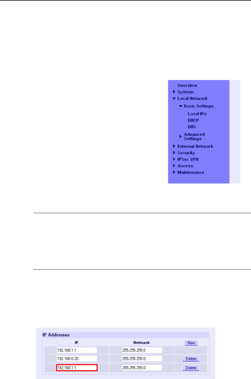
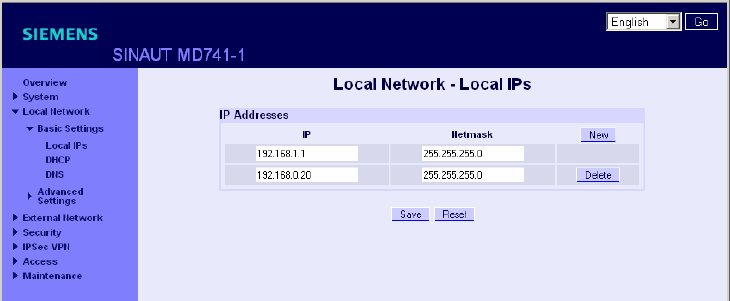
4.1 IP addresses of the local interface
This is where the IP addresses and the netmasks at which the SINAUT MD741-1
can be reached by local applications are set.
Figure 4-1 Local Network > Basic Settings > Local IPs
Local interface
SINAUT MD741-1
40 C79000- G8976-C212
The factory settings for the SINAUT MD741-1 are as follows:
IP 192.168.1.1
Netmask 255.255.255.0
These factory-set IP addresses and netmasks can be changed freely, but should
follow the applicable recommendations (RFC 1918).
MD741-1
Admin PC
Local
application Local
application Local
application
Local IP
and
netmask
Figure 4-2 Local interface
You can define additional addresses at which the SINAUT MD741-1 can be
reached by local applications. This is useful, for example, when the local network is
subdivided into subnetworks. Then multiple local applications from different
subnetworks can reach the SINAUT MD741-1 under various addresses.
New
Adds additional IP addresses and netmasks, which you can then modify in turn.
Delete
Removes the respective IP address and netmask. The first entry cannot be
deleted.

Local interface
SINAUT MD741-1
C79000- G8976-C212 41
4.2 DHCP server to local network
The SINAUT MD741-1 contains a DHCP server (DHCP = Dynamic Host
Configuration Protocol). If the DHCP server is switched on, it automatically assigns
to the applications that are connected to the local interface of the SINAUT MD741-
1 the IP addresses, netmasks, the gateway and the DNS server. This is only
possible the setting for obtaining the IP address and the configuration parameter
automatically via DHCP is activated for the local applications.
MD741-1
PC with
Web browser
Local
application Local
application Local
application
IP addresses
and so forth
Figure 4-3 DHCP function on local interface
Figure 4-4 Local Network > Basic Settings > Local IPs
Start DHCP server
Start DHCP server – Yes switches on the DHCP server of the SINAUT MD741-1;
No switches it off.

Local interface
SINAUT MD741-1
42 C79000- G8976-C212
Local netmask
Here enter the local netmask that should be assigned to the local applications.
Default gateway
Here enter the default gateway that should be assigned to the local applications.
DNS server
Here enter the DNS server that should be assigned to the local applications.
Enable dynamic IP address pool
With Yes the IO addresses that the DHCP server of the SINAUT MD741-1 assigns
are drawn from a dynamic address pool.
With No the IP addresses must be assigned to the MAC addresses of the local
application under Static Leases.
DHCP range start
Specifies the first address of the dynamic address pool.
DHCP range end
Specifies the last address of the dynamic address pool.
Static Leases
In Static Leases of the IP addresses you can assign corresponding IP addresses to
the MAC addresses of local applications.
If a local application requests assignment of an IP address via DHCP, the
application communicates its MAC address with the DHCP query. If an IP address
is statically assigned to this MAC address the SINAUT MD741-1 assigns the
corresponding IP address to the application.
MAC address of the client – MAC address of the querying local application
IP address of the client – assigned IP address
Local interface
SINAUT MD741-1
C79000- G8976-C212 43
Factory setting
The factory settings for the SINAUT MD741-1 are as follows:
Start DHCP server No
Local netmask 255.255.255.0
Default gateway 192.168.1.1
DNS server 192.168.1.1
Enable dynamic IP address pool No
DHCP range start 192.168.1.100
DHCP range end 192.168.1.199
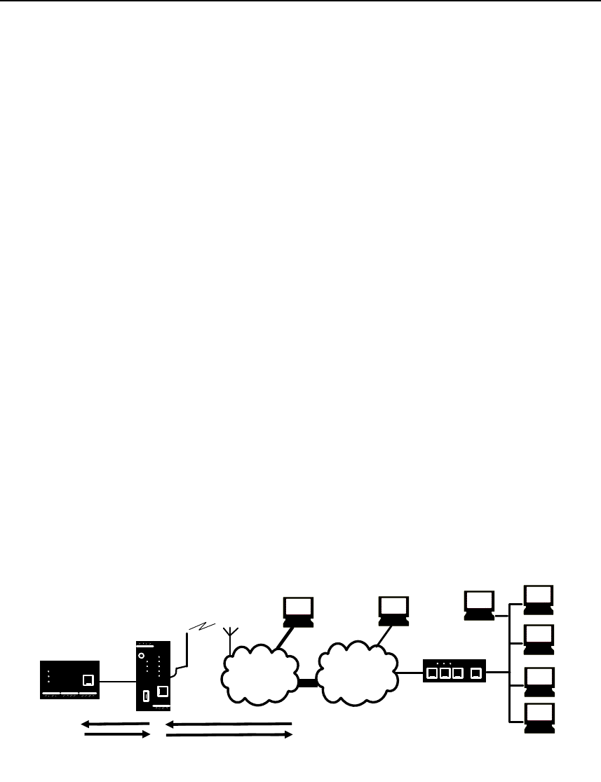
4.3 DNS to local network
The SINAUT MD741-1 provides a domain name server (DNS) to the local network.
If you enter the IP address of the SINAUT MD741-1 in your local application as the
domain name server (DNS), then the SINAUT MD741-1 answers the DNS queries
from its cache. If it does not know the corresponding IP address for a domain
address, then the SINAUT MD741-1 forwards the query to an external domain name
server (DNS).
APN
(E-)GPRS INTERNET
MD741-1
Local
application
Router/
Firewall
Remote network
DNS query
by MD741-1
DNS of the
network provider DNS in the
Internet
Private
DNS
DNS query
to MD741-1
Figure 4-5 DNS function on local interface
The time period for which the SINAUT MD741-1 holds a domain address in the
cache depends on the host being addressed. In addition to the IP address, a DNS
query to an external domain name server also supplies the life span of this
information.
Local interface
SINAUT MD741-1
44 C79000- G8976-C212
The external domain name server (DNS) used can be a server of the network
operator, a server on the Internet, or a server in a private external network.
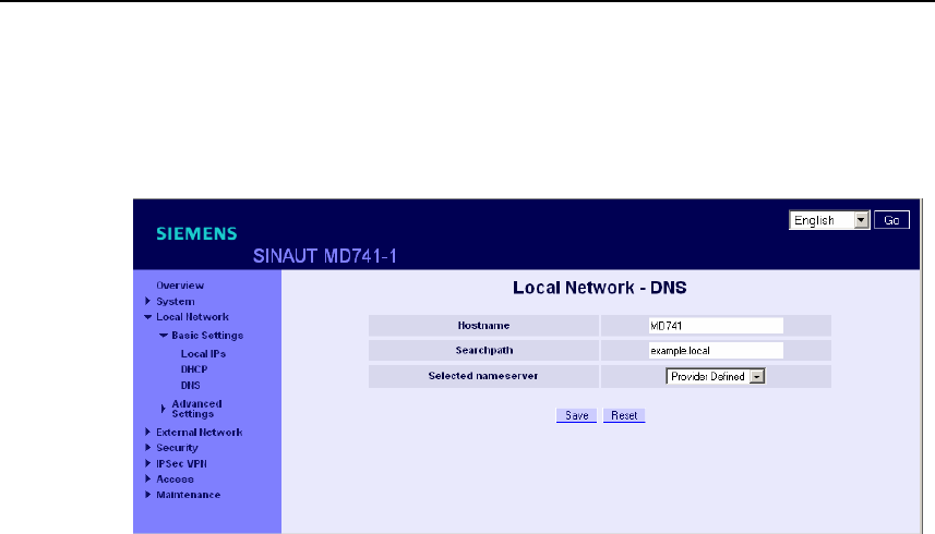
Figure 4-6 Local Network > Basic Settings > DNS
Selected nameserver
Select which domain name server (DNS) the SINAUT MD741-1 should query.
Provider Defined
When a connection is established to EGPRS or GPRS the network operator
automatically communicates one or more DNS addresses. These are then used.
Root Nameserver
Queries are directed to the root nameservers on the Internet whose IP addresses
are stored in the SINAUT MD741-1. Select this setting only if the alternative
settings do not work.
User Defined
As the user you select your preferred DNS. The DNSes can be connected to the
Internet, or it can be a private DNS in your network.
User defined nameserver
If you have selected the option User Defined then enter the IP address of the
selected DNS as the Server IP Address.
New can be used to add additional DNSes.
Local interface
SINAUT MD741-1
C79000- G8976-C212 45
Factory setting
The factory settings for the SINAUT MD741-1 are as follows:
Selected nameserver Provider Defined
User defined nameserver
for new entry
-
0.0.0.0
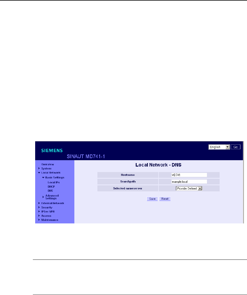
4.4 Local hostname
The SINAUT MD741-1 can also be addressed from the local network using a host
name. To do this, define a host name, e.g. MD741.
Figure 4-7 Local Network > Basic Settings > DNS
The SINAUT MD741-1 can then be called up, for example from a Web browser as
MD741.
Note
The security concept of the SINAUT MD741-1 requires the creation of an outgoing
firewall rule for each local application that is to use this hostname function. See
Chapter 6.1.
If you do not use DHCP (see Chapter 4.2), then identical search paths have to be
entered manually in the SINAUT MD741-1 and in the local applications. If you do
use DHCP, the local applications received the search path entered in the SINAUT
MD741-1 via DHCP.
Factory setting
The factory settings for the SINAUT MD741-1 are as follows:
Searchpath example.local
Hostname md741
Local interface
SINAUT MD741-1
46 C79000- G8976-C212
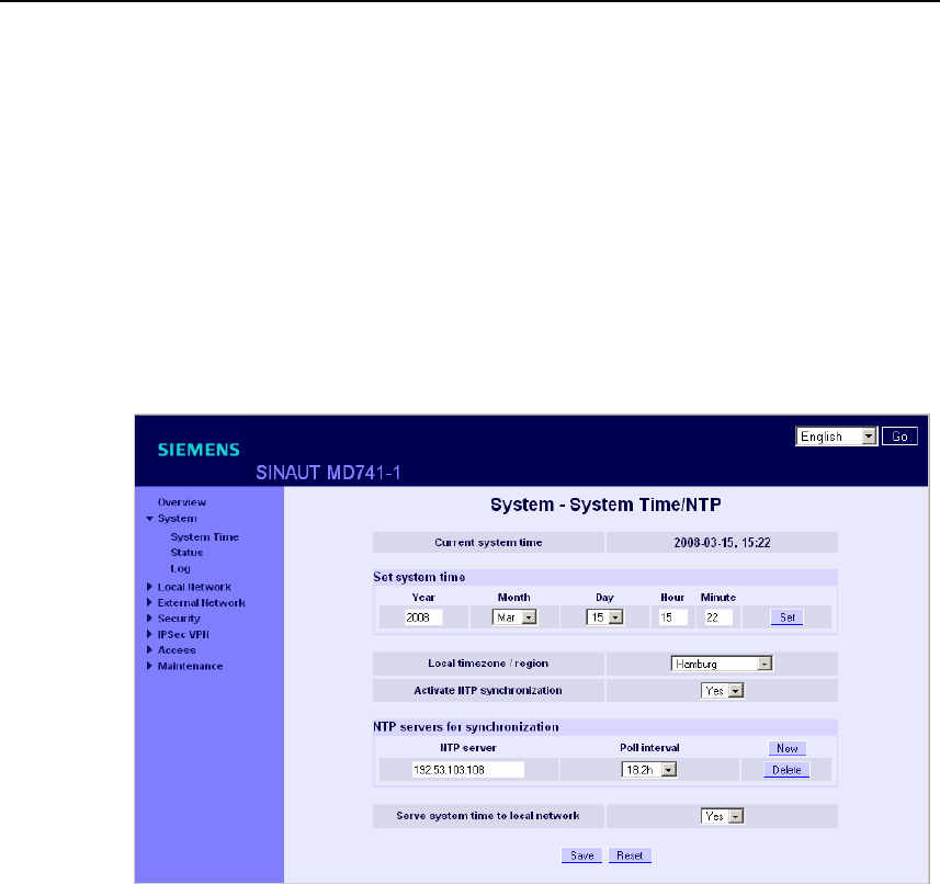
4.5 System Time/NTP
This is where you set the system time for the SINAUT MD741-1. This system time
is:
● used as a time stamp for all log entries, and
● serves as a time basis for all time-controlled functions.
Select the year, month, day, hour and minute.
Figure 4-8 System > System Time/NTP
Activate NTP synchronization
The SINAUT MD741-1 can also obtain the system time from a time server via NTP
(= Network Time Protocol). There are a number of time servers on the Internet that
can be used to obtain the current time very precisely via NTP.
Local timezone / region
The NTP time servers communicate the UTC (= Universal Time Coordinated). To
specify the time zone, select a city near the location near where the SINAUT
MD741-1 will be operating. The time in this time zone will then be used as the
system time.

Local interface
SINAUT MD741-1
C79000- G8976-C212 47
NTP server
Click on New to add an NTP server, and enter the IP address of such an NTP
server, or use the NTP server preset at the factory. You can specify multiple NTP
servers at the same time.
It is not possible to enter the NTP address as a hostname (e.g. timeserver.org).
Poll interval
The time synchronization is carried out cyclically. The interval at which
synchronization is performed is determined by the SINAUT MD741-1 automatically.
A new synchronization will be carried out at least once every 36 hours. The poll
interval defines the minimum period that the SINAUT MD741-1 waits until the next
synchronization.
Note
Synchronization of the system time via NTP creates additional data traffic on the
EGPRS or GPRS interfaces. This may result in additional costs, depending on your
user agreement with the GSM network operator.
Serve system time to local network
The SINAUT MD741-1 can serve itself as an NTP time server for the applications
that are connected to its local network interface. To activate this function select
Yes.
The NTP time server in the SINAUT MD741-1 can be reached via the local IP
address set for the SINAUT MD741-1, see Chapter 4.1.
Factory setting
The factory settings for the SINAUT MD741-1 are as follows:
Local timezone UTC
Activate NTP synchronization No
NTP server 192.53.103.108
Poll interval 1.1 hours
Serve system time to local network No

Local interface
SINAUT MD741-1
48 C79000- G8976-C212
4.6 Additional Internal Routes
If the local network is subdivided into subnetworks, you can define additional
routes.
See also the Glossary.
To define an additional route to a subnetwork, click on New.
Specify the following:
● the IP address of the subnetwork (network), and also
● the IP address of the gateway via which the subnet is connected.
You can define any desired number of internal routes.
To delete an internal route, click on Delete.
Factory setting
The factory settings for the SINAUT MD741-1 are as follows:
Additional Internal Routes -
Default for new routes: No
Network: 192.168.2.0/24
Gateway: 192.168.0.254
SINAUT MD741-1
C79000- G8976-C212 49
External interface 5
The external interface of the SINAUT MD741-1 connects the SINAUT MD741-1 to
the external network. EGPRS, GPRS or GSM are used for the communication at
this interface.
External networks are the Internet or a private intranet.
External remote stations are network components in an external network, e.g. Web
servers on the Internet, routers on an intranet, a central company server, an Admin
PC, and much more.
Configure the external interface and the related functions according to the your
requirements and the advices in this chapter.
5.1 Access parameters to EGPRS/GPRS
The SINAUT MD741-1 uses EGPRS or GPRS for communication with the external
network. For access to the services EGPRS and GPRS and to the underlying GSM
wireless network, access parameters are necessary, which you will receive from
your GSM network operator.
(E-)GPRS
INTERNET
MD741-1
Local
application
VPN
SIM
PIN Username
and password APN
(public)
APN
(private)
Figure 5-1 Access parameters to EGPRS/GPRS
External interface
SINAUT MD741-1
50 C79000- G8976-C212
The PIN protects the SIM card against unauthorised use. The user name and
password protect the access to EGPRS and GPRS and the APN (Access Point
Name) defines the transition from EGPRS or GPRS to additional connected IP
networks, for example a public APN to the Internet or a private APN to a virtual
private network (VPN).
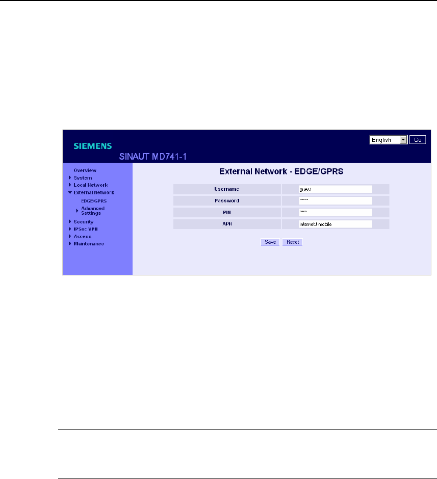
Figure 5-2 External Network > EDGE/GPRS
PIN
Enter the PIN for your SIM card here. You will receive the PIN from your network
operator.
The SINAUT MD741-1 also works with SIM cards that have no PIN; in this case
enter NONE. In this case the input box is left empty.
Note
If no entry is made, the input box for the PIN is shown with a red outline after
saving.
User name
Enter the user name for EGPRS and GPRS here. Some GSM/GPRS network
operators do not use access control with user names and/or passwords. In this
case enter guest in the corresponding box.
Password
Enter the password for EGPRS and GPRS here. Some GSM/GPRS network
operators do not use access control with user names and/or passwords. In this
case enter guest in the corresponding box.
External interface
SINAUT MD741-1
C79000- G8976-C212 51
APN
Enter the name of the transition from EGPRS and GPRS to other networks here.
You can find the APN in your GSM/GPRS network operator's documentation, on
your operator's Website, or ask your operator's hotline.
Factory setting
The factory settings for the SINAUT MD741-1 are as follows:
PIN NONE
User name guest
Password guest
APN NONE
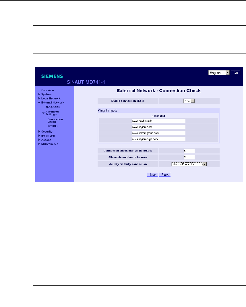
5.2 EGPRS/GPRS Connection Monitoring
With the function Connection Check the SINAUT MD741-1 checks its connection to
EGPRS or GPRS and to the connected external networks, such as the Internet or
an intranet. To do this, the SINAUT MD741-1 sends ping packets (ICMPs) to up to
four remote stations (target hosts) at regular intervals. This takes place
independently of the user data connections. If after such a ping the SINAUT
MD741-1 receives a response from at least one of the remote stations addressed,
then the SINAUT MD741-1 is still connected with the EGPRS or GPRS and ready
for operation.
Some network operators interrupt connections when they are inactive. This is
likewise prevented by the Connection Check function.
APN
(E-)GPRS INTERNET
MD741-1
Local
application
Router/
Firewall
Remote network
Destination host
on the Intranet
User data connection
Destination host
on the Internet
Ping for connection
monitoring
Figure 5-3 Connection Monitoring
External interface
SINAUT MD741-1
52 C79000- G8976-C212
Warning
Sending ping packets (ICMPs) increases the amount of data sent and received via
EGPRS or GPRS. This can lead to increased costs.
Figure 5-4 External Network > Connection Check
Enable connection check
Yes activates the function.
Ping Targets – Hostname
Select up to four remote stations that the SINAUT MD741-1 can ping. The remote
stations must be available continuously and must answer pings.
Note
Make sure that the selected remote stations will not be disturbed.
Connection check interval (minutes)
Specifies the interval at which the connection check ping packets are sent by the
SINAUT MD741-1. This is specified in minutes.

External interface
SINAUT MD741-1
C79000- G8976-C212 53
Allowable number of failures
Specifies how many times it is allowed for all ping packets of an interval not to
receive an answer, i.e. for none of four pinged remote stations to answer, before
the specified action is carried out.
Activity on faulty connection
Renew Connection
The SINAUT MD741-1 re-establishes the connection to EGPRS or GPRS if the
ping packets sent were not answered.
Reboot MD741
The SINAUT MD741-1 carries out a reboot if the ping packets sent were not
answered.
Factory setting
The factory settings for the SINAUT MD741-1 are as follows:
Enable connection check No (switched off)
Hostname -
Connection check interval 5 (minutes)
Allowable number of failures 3 (failed attempts)
Activity on faulty connection Renew Connection
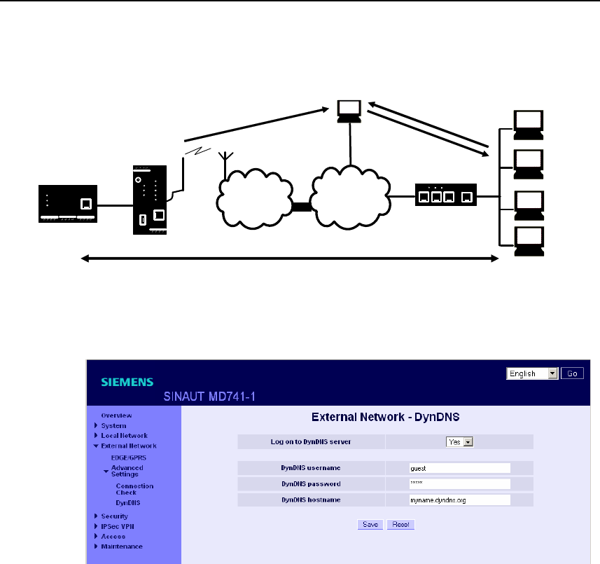
5.3 Hostname via DynDNS
Dynamic domain name servers (DynDNS) make it possible for applications to be
accessible on the Internet under a hostname (e.g. myHost.org), even if these
applications do not have a fixed IP address and the hostname is not registered. If
you log the SINAUT MD741-1 on to a DynDNS service, you also can reach the
SINAUT MD741-1 from external network under a hostname, e.g.
mySINAUT.dyndns.org.
For more information on DynDNS see the Glossary.
External interface
SINAUT MD741-1
54 C79000- G8976-C212
APN
(E-)GPRS INTERNET
MD741-1
Local
application
Router/
Firewall
External network
User data connection
DynDNS
INFO: IP address +
hostname Question: IP for the
hostname
Response: IP
Figure 5-5 DynDNS Function
Figure 5-6 External Network > DynDNS
Log this SINAUT MD741-1 on to a DynDNS server
Select Yes if you want to use a DynDNS service.
DynDNS provider
The SINAUT MD741-1 is compatible to dyndns.org.
DynDNS username / password
Enter here the username and the password that authorise you to use the DynDNS
service. Your DynDNS provider will give you this information.

External interface
SINAUT MD741-1
C79000- G8976-C212 55
DynDNS hostname
Here enter the hostname that you have agreed with your DynDNS provider for the
SINAUT MD741-1, e.g. myMD741.dyndns.org.
Factory setting
The factory settings for the SINAUT MD741-1 are as follows:
Log the MD741-1 on to DynDNS server No (switched off)
DynDNS username guest
DynDNS password guest
DynDNS hostname myname.dyndns.org

External interface
SINAUT MD741-1
56 C79000- G8976-C212
SINAUT MD741-1
C79000- G8976-C212 57
Security functions 6
6.1 Packet Filter
The SINAUT MD741-1 contains a stateful inspection firewall.
A stateful inspection firewall is a packet filtering method. Packet filters only let IP
packets through if this has been defined previously using firewall rules. The
following is defined in the firewall rules:
● which protocol (TCP, UDP, ICMP) can go through,
● the permitted source of the IP packets (From IP / From port)
● the permitted destination of the IP packets (To IP / To port)
It is likewise defined here what will be done with IP packets that are not allowed
through (discard, reject).
For a simple packet filter it is always necessary to create two firewall rules for a
connection:
● One rule for the query direction from the source to the destination, and
● a second rule for the query direction from the destination to the source.
It is different for a SINAUT MD741-1 with a stateful inspection firewall. Here a
firewall rule is only created for the query direction from the source to the
destination. The firewall rule for the response direction from the destination to the
source results from analysis of the data previously sent. The firewall rule for the
responses is closed again after the responses are received or after a short time
period has elapsed. Thus responses can only go through if there was a previous
query. This means that the response rule cannot be used for unauthorised access.
What is more, special procedures make it possible for UDP and ICMP data to also
go through, even though these data were not requested before.
Security functions
SINAUT MD741-1
58 C79000- G8976-C212
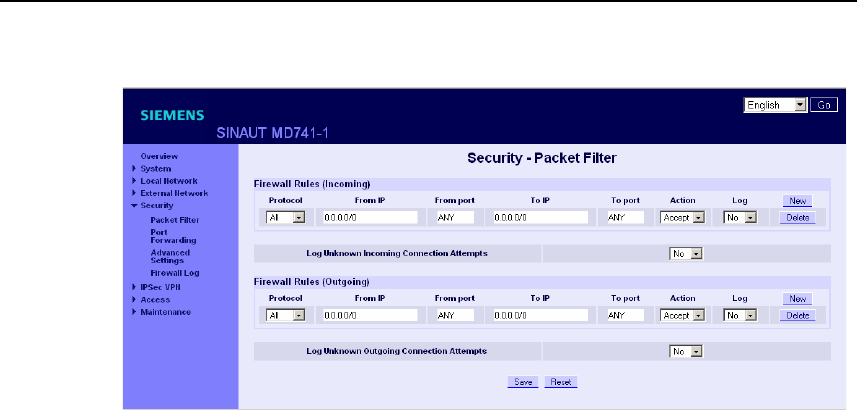
Figure 6-1 Security > Packet Filter
Firewall Rules (Incoming)
The Firewall Rules (Incoming) are used to define how to handle IP packets that are
received from external networks (e.g. the Internet) via EGPRS or GPRS. The
source is the sender of this IP packet. The destination is the local applications on
the SINAUT MD741-1.
In the factory setting, no incoming firewall rule is set initially, i.e. no IP packets can
go through.
New
Adds an additional firewall rule that you can then fill out.
Delete
Removes firewall rules that have been created.
Protocol
Select the protocol for which this rule will be valid. The following selections are
available: TCP, UDP, ICMP. If you select All, the rule is valid for all three protocols.
From IP
Enter the IP address of the external remote station that is allowed to send IP
packets to the local network. Do this by specifying the IP address or an IP range for
the remote station. 0.0.0.0/0 means all addresses.
To specify a range, use the CIDR notation - see the Glossary.
From port
Enter the port from which the external remote station is allowed to send IP packets.
(is only evaluated for the protocols TCP and UDP)

Security functions
SINAUT MD741-1
C79000- G8976-C212 59
To IP
Enter the IP address in the local network to which IP packets may be sent. Do this
by specifying the IP address or an IP range of the application in the local network.
0.0.0.0/0 means all addresses.
To specify a range, use the CIDR notation - see the Glossary.
To port
Enter the port to which the external remote station is allowed to send IP packets.
Action
Select how incoming IP packets are to be handled:
Accept – The data packets can go through,
Reject – The data packets are rejected, and the sender receives a corresponding
message.
Drop – The data packets are discarded without any feedback to the sender.
Firewall Rules (Outgoing)
The Firewall Rules (Outgoing) are used to define how to handle IP packets that are
received from the local network. The source is an application in the local network.
The destination is an external remote station, e.g. on the Internet or in a private
network.
In the factory setting, no outgoing firewall rule is set initially, i.e. no IP packets can
go through.
New
Adds an additional firewall rule that you can then fill out.
Protocol
Select the protocol for which this rule will be valid. The following selections are
available: TCP, UDP, ICMP. If you select All, the rule is valid for all three protocols.
From IP
Enter the IP address of the local application that is allowed to send IP packets to
the external network. Do this by specifying the IP address or an IP range for the
local application. 0.0.0.0/0 means all addresses.
To specify a range, use the CIDR notation - see the Glossary.

Security functions
SINAUT MD741-1
60 C79000- G8976-C212
From port
Enter the port from which the local network is allowed to send IP packets. Do this
by specifying the port number.
(is only evaluated for the protocols TCP and UDP)
To IP
Enter the IP address in the external network to which IP packets may be sent. Do
this by specifying the IP address or an IP range of the application in the network.
0.0.0.0/0 means all addresses.
To specify a range, use the CIDR notation - see the Glossary.
To port
Enter the port to which the external remote station is allowed to send IP packets.
Do this by specifying the port number.
(is only evaluated for the protocols TCP and UDP)
Action
Select how outgoing IP packets are to be handled:
Accept – The data packets can go through,
Reject – The data packets are rejected, and the sender receives a corresponding
message.
Drop – The data packets are discarded without any feedback to the sender.
Firewall Rules Incoming / Outgoing
Log
For each individual firewall rule you can define whether the event should be
● logged when the rule takes effect - set Log to Yes
● or not - set Log to No (factory setting)
The log is kept in the firewall log, see Chapter 6.4.
Log Unknown Connection Attempts
This logs all connection attempts that are not covered by the defined rules.

Security functions
SINAUT MD741-1
C79000- G8976-C212 61
Factory setting
The factory settings for the SINAUT MD741-1 are as follows:
Incoming firewall
Firewall Rules (Incoming) - (Everything blocked)
Protocol All
From IP 0.0.0.0/0
From port Any
To IP 0.0.0.0/0
To port Any
Action Accept
Log No (switched off)
Log Unknown Connection Attempts No (switched off)
Outgoing firewall
Firewall Rules (Outgoing) - (Everything blocked)
Protocol All
From IP 0.0.0.0/0
From port Any
To IP 0.0.0.0/0
To port Any
Action Accept
Log No (switched off)
Log Unknown Connection Attempts No (switched off)
Security functions
SINAUT MD741-1
62 C79000- G8976-C212
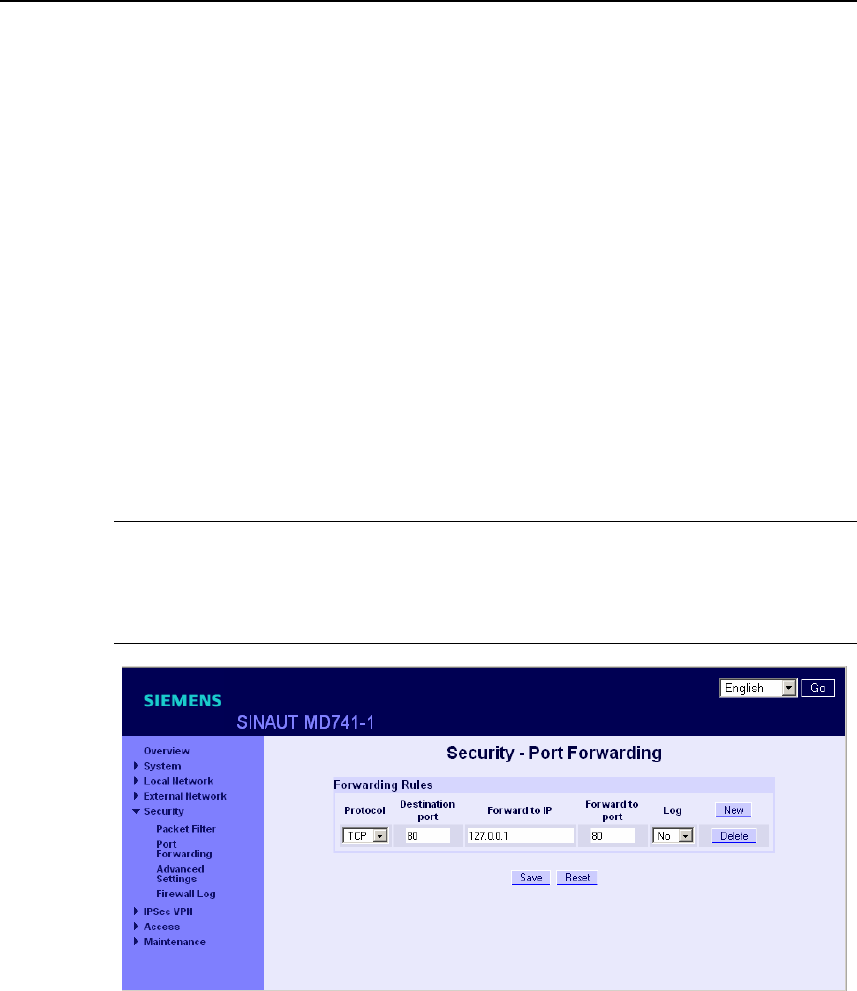
6.2 Port Forwarding
If a rule has been created for port forwarding, then data packets received at a
defined IP port of the SINAUT MD741-1 from the external network will be
forwarded. The incoming data packets are then forwarded to a specified IP address
and port number in the local network. The port forwarding can be configured for
TCP or UDP.
In port forwarding the following occurs: The header of incoming data packets from
the external network that are addressed to the external IP address of the SINAUT
MD741-1 and to a specific port are adapted so that they are forwarded to the
internal network to a specific computer and to a specific port of that computer.
This means that the IP address and port number in the header of incoming data
packets are modified.
This process is also called Destination NAT or Port Forwarding.
Note
In order for incoming data packets to be forwarded to the defined IP address in the
local network, a corresponding incoming firewall rule must be set up for this IP
address in the packet filter. See Chapter 6.1.
Figure 6-2 Security > Port Forwarding
New
Adds a new forwarding rule that you can then fill out.
Delete
Removes forwarding rules that have been created.
Protocol
Specify here the protocol (TCP or UDP) to which the rule should refer.

Security functions
SINAUT MD741-1
C79000- G8976-C212 63
Destination port
Specify here the port number (e.g. 80) at which the data packets which are to be
forwarded arrive from the external network.
Forward to IP
Specify here the IP address in the local network to which the incoming data
packets should be forwarded.
Forward to port
Specify here the port number (e.g.) for the IP address in the local network to which
the incoming data packets should be forwarded.
Log
For each port forwarding rule you can define whether the event should be
● logged when the rule takes effect - set Log to Yes
● or not - set Log to No (factory setting)
The log is kept in the firewall log, see Chapter 6.4.
Factory setting
The factory settings for the SINAUT MD741-1 are as follows:
Forwarding Rules -
Protocol All
Destination port 80
Forward to IP 127.0.0.1
Forward to port 80
Log No (switched off)
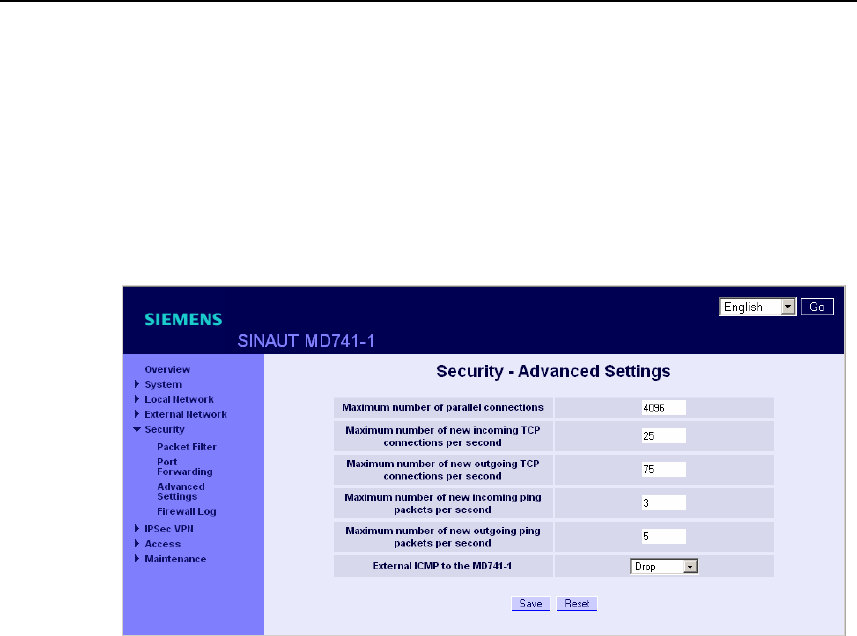
Security functions
SINAUT MD741-1
64 C79000- G8976-C212
6.3 Advanced security functions
The advanced security functions serve to protect the SINAUT MD741-1 and the
local applications against attacks. For protective purposes it is assumed that only a
certain number of connections or received PING packets are permissible and
desirable in normal operation, and that a sudden burst represents an attack.
Figure 6-3 Security > Advanced Settings
Maximum number …
The entries
● Maximum number of parallel connections
● Maximum number of new incoming TCP connections per second
● Maximum number of new outgoing TCP connections per second
● Maximum number of new incoming ping packets per second
● Maximum number of new outgoing ping packets per second
set the upper limits. The settings (see illustration) have been selected so that they
will in practice never be reached in normal use. In the event of an attack, however,
they can be reached very easily, which means that the limitations constitute
additional protection. If your operating environment contains special requirements,
then you can change the values accordingly.

Security functions
SINAUT MD741-1
C79000- G8976-C212 65
External ICMP to the SINAUT MD741-1
You can use this option to affect the response when ICMP packets are received
that are sent from the external network in the direction of the SINAUT MD741-1.
You have the following options:
● Drop: All ICMP packets to the SINAUT MD741-1 are discarded.
● Allow Ping: Only ping packets (ICMP type 8) to the SINAUT MD741-1 are
accepted.
● Accept: All types of ICMP packets to the SINAUT MD741-1 are accepted.
Factory setting
The factory settings for the SINAUT MD741-1 are as follows:
Maximum number of parallel connections 4096
Maximum number of new incoming TCP
connections per second
25
Maximum number of new outgoing TCP
connections per second
75
Maximum number of new incoming ping
packets per second
3
Maximum number of new outgoing ping
packets per second
5
External ICMP to the MD741-1 Drop
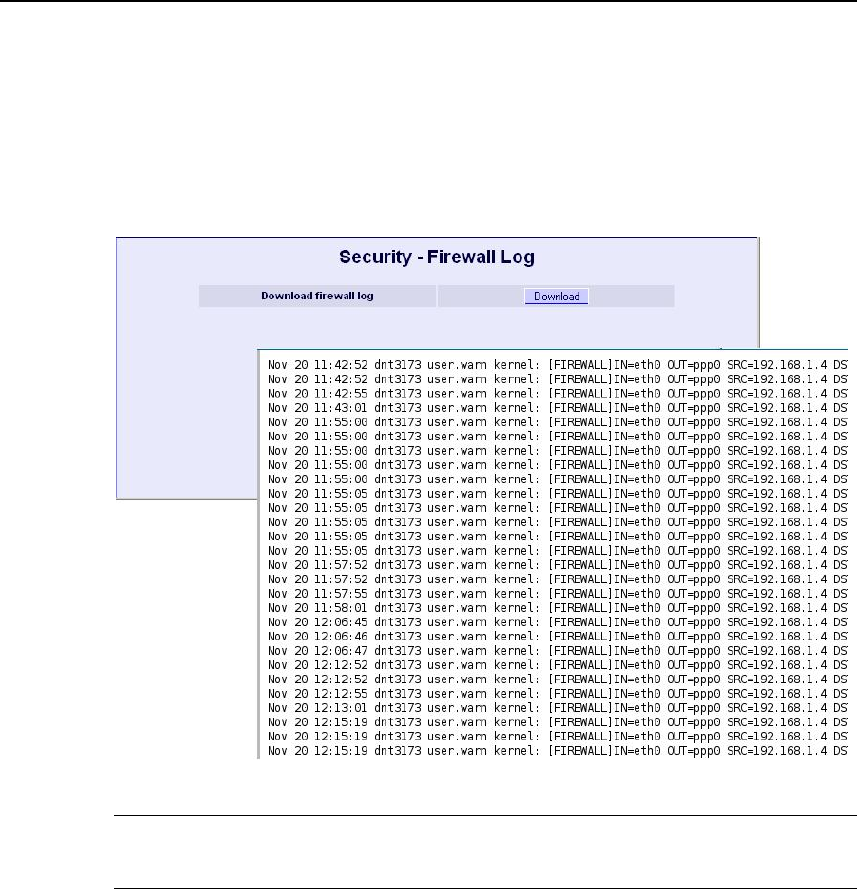
Security functions
SINAUT MD741-1
66 C79000- G8976-C212
6.4 Firewall Log
The application of individual firewall rules is recorded in the firewall log. To do this,
the LOG function must be activated for the various firewall functions.
Figure 6-4 Security > Firewall Log
Caution
The firewall log is lost in the event of a reboot.
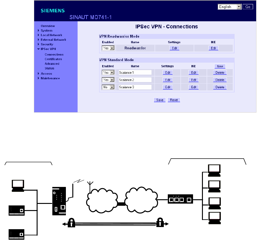
SINAUT MD741-1
67 C79000- G8976-C212
VPN connection 7
The SINAUT MD741-1 can connect the local network to a friendly remote network via a VPN
tunnel. The IP data packets that are exchanged between the two networks are encrypted, and
are protected against unauthorised tampering by the VPN tunnel. This means that even
unprotected public networks like the Internet can be used to transfer data without endangering
the confidentiality or integrity of the data.
Figure 7-1 IPsec VPN > Connections
For the SINAUT MD741-1 to establish a VPN tunnel, the remote network must
have a VPN gateway as the remote station for the SINAUT MD741-1.
APN
(E-)GPRS INTERNET
MD741-1
VPN gateway
Local network Remote network
Local
application
Admin PC
Local
applikation
Admin PC
External
remote
stations
VPN tunnel
Figure 7-2 IPsec VPN - Connections

VPN connection
SINAUT MD741-1
68 C79000- G8976-C212
For the VPN tunnel, the SINAUT MD741-1 uses the IPsec method in tunnel mode.
In this method the IP data packets to be transmitted are completely encrypted and
provided with a new header before they are sent to the remote station's VPN
gateway. There the data packets are received, decrypted, and used to reconstruct
the original data packets. These are then forwarded to their destination in the
remote network.
Differences between two VPN connection modes:
● In VPN Roadwarrior Mode the SINAUT MD741-1 VPN can accept connections
from remote stations with an unknown address. These can be, for example,
remote stations in mobile use that obtain their IP address dynamically.
The VPN connection must be established by the remote station. Only one VPN
connection is possible in Roadwarrior Mode. VPN connections in Standard
Mode can be used at the same time.
● In VPN Standard Mode the address (IP address or hostname) of the remote
station's VPN gateway must be known for the VPN connection to be
established. The VPN connection can be established either by the SINAUT
MD741-1 or by the remote station's VPN gateway as desired.
Establishment of the VPN connection is subdivided into two phases: First in Phase
1 (ISAKMP = Internet Security Association and Key Management Protocol) the
Security Association (SA) for the key exchange between the SINAUT MD741-1 and
the VPN gateway of the remote station is established.
After that in Phase 2 (IPsec = Internet Protocol Security) the Security Association
(SA) for the actual IPsec connection between the SINAUT MD741-1 and the
remote station's VPN gateway is established.
Requirements for the remote network's VPN gateway
In order to successfully establish an IPsec connection, the VPN remote station
must support IPsec with the following configuration:
● Authentication via X.509 certificates, CA certificates or pre-shared key (PSK)
● ESP
● Diffie-Hellman group 1, 2 or 5
● 3DES or AES encryption
● MD5 or SHA-1 hash algorithms
● Tunnel Mode
● Quick Mode
● Main Mode
● SA Lifetime (1 second to 24 hours)
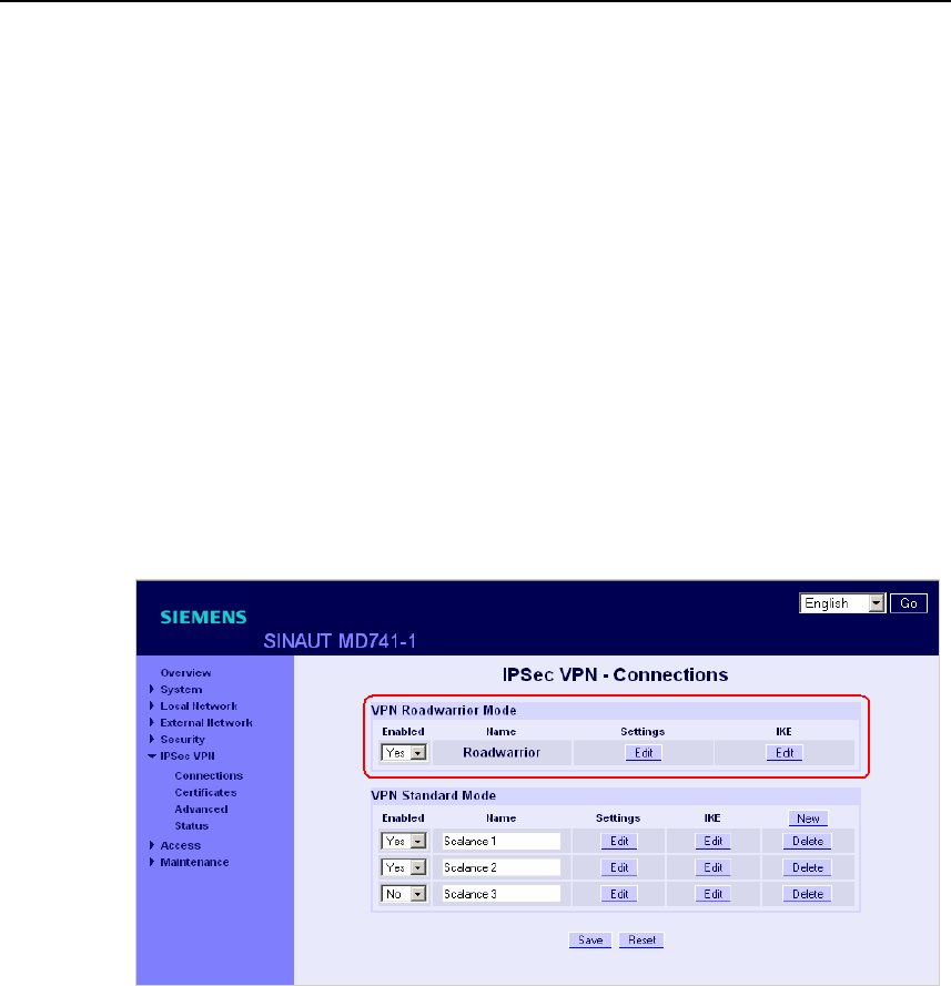
VPN connection
SINAUT MD741-1
C79000- G8976-C212 69
If the remote station is a computer running under Windows 2000, then the
Microsoft Windows 2000 High Encryption Pack or at least Service Pack 2 must
also be installed.
If the remote station is on the other side of a NAT router, then the remote station
must support NAT-T. Or else the NAT router must know the IPsec protocol
(IPsec/VPN passthrough).
7.1 VPN Roadwarrior Mode
The Roadwarrior Mode makes it possible for the SINAUT MD741-1 VPN to accept
a VPN connection initiated by a remote station with an unknown IP address. The
remote station must authenticate itself properly; in this VPN connection there is no
identification of the remote station based on the IP address or the hostname of the
remote station.
Figure 7-3 IPsec VPN > Connections
Set the SINAUT MD741-1 up in accordance with what has been agreed with the
system administrator of the remote station.
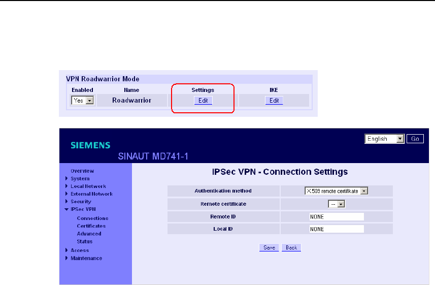
VPN connection
SINAUT MD741-1
70 C79000- G8976-C212
Roadwarrior Mode Edit Settings
Figure 7-4 IPsec VPN > Connection Settings
Function
Set the SINAUT MD741-1 up in accordance with what has been agreed with the
system administrator of the remote station.
Authentication method
Select the authentication method in accordance with what you have agreed with
the system administrator of the remote station.
The SINAUT MD741-1 supports three methods:
● X.509 certificate
● CA certificate
● Pre-shared key
X.509 certificate, CA certificate
In the authentication methods X.509 certificate and CA certificate, the keys used
for authentication have first been signed by a Certification Authority (CA). This
method is considered especially secure. A CA can be a service provider, but also,
for example, the system administrator for your project, provided that he has the
necessary software tools.

VPN connection
SINAUT MD741-1
C79000- G8976-C212 71
The CA creates a certificate file (PKCS12) with the file extension *p12 for each of
the two remote stations. This certificate file contains the public and private keys for
the own station, the signed certificate from the CA, and the public key of the CA.
For the authentication method X.509 there is additionally a key file (*.pem, *cer or
*.crt) for each of the two remote stations with the public key of the own station.
X.509 certificate
The public keys (files with extension *.pem, *cer or *.crt) are exchanged between
the SINAUT MD741-1 and the remote station's VPN gateway takes place
manually, for example on a CD-ROM or vie e-mail. To load the certificate, proceed
as described in Chapter 7.3.
CA certificate
The public keys are exchanged between the SINAUT MD741-1 and the remote
station's VPN gateway via the data connection when the VPN connection is
established. Manual exchange of the key files is not necessary.
Pre-shared secret key (PSK)
This method is primarily supported by older IPsec implementations. Here
authentication is performed with a character string agreed on beforehand. In order
to obtain high security, the character string should consist of about randomly-
selected 30 lower-case and upper-case letters and numerals.
Remote certificate
If you have selected X.509 certificate as the authentication method, then a list of
the remote certificates that you have already loaded into the SINAUT MD741-1 is
displayed here. Select the certificate for the VPN connection.
Remote ID, Local ID
The Local ID and the Remote ID are used by IPsec to identify the remote stations
uniquely when establishing the VPN connection. The own Local ID constitutes the
Remote ID of the remote station and vice versa.
For authentication with X.509 certificate or CA certificate:
● If you keep the factory setting NONE, then the Distinguished Names from the
own certificate and from the certificate communicated by the remote station are
automatically used as the Local ID and Remote ID.
• If you manually change the entry for the Local ID or the Remote ID, then the
corresponding entries must be adapted at the remote station. The manual entry
for Local or Remote ID must be made in the ASN.1 format, e.g. "C=XY/O=XY
Org/CN=xy.org.org"
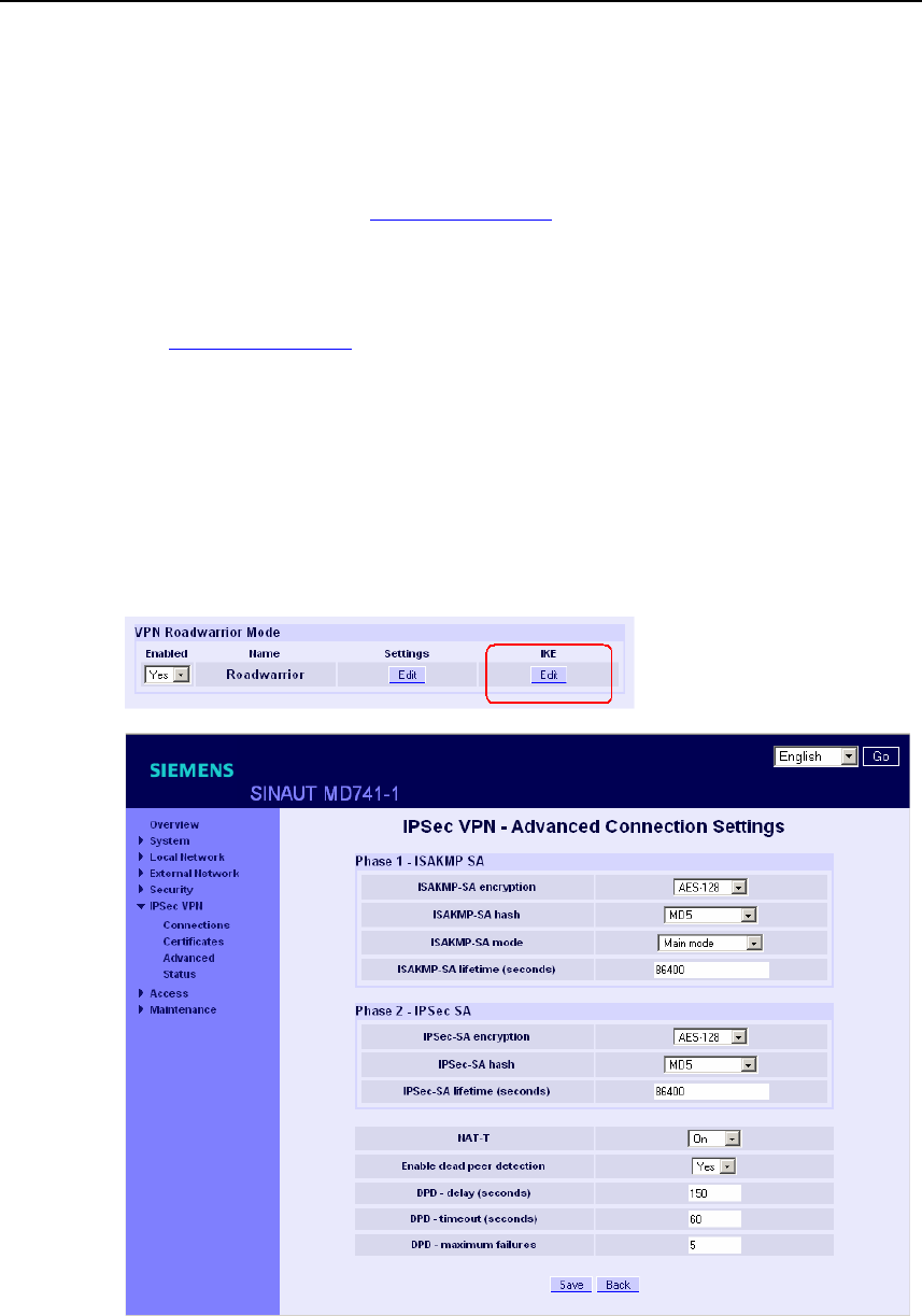
VPN connection
SINAUT MD741-1
72 C79000- G8976-C212
For authentication with pre-shared secret key (PSK):
● In Roadwarrior Mode the Remote ID must be entered manually. The Remote
ID must have the format of a hostname (e.g. RemoteStation.de) or the format
of an e-mail address (remote@station.de), and must be the same as the Local
ID of the remote station.
The Local ID can be left on NONE. In this case the IP address is used as the
local IP address. If you enter a Local ID; then it must have the format of a
hostname (e.g. RemoteStation.de) or the format of an e-mail address
(remote@station.de), and must be the same as the Local ID of the remote
station.
Roadwarrior Mode Edit IKE
Here you can define the properties of the VPN connection according to your
requirements and what you have agreed with the system administrator of the
remote station.
Figure 7-5 IPsec VPN > IKE bearbeiten

VPN connection
SINAUT MD741-1
C79000- G8976-C212 73
ISAKMP-SA encryption, IPsec-SA encryption
Agree with the administrator of the remote station which encryption method will be
used for the ISAKMP-SA and the IPsec-SA. The SINAUT MD741-1 supports the
following methods:
● 3DES-168
● AES-128
● AES-192
● AES-256
3DES-168 is a commonly used method and is therefore set as the default.
The method can be defined differently for ISAKMP-SA and IPsec-SA.
Note:
The more bits in the encryption algorithm - indicated by the appended number - the
more secure it is. The method AES-256 is therefore considered the most secure.
However, the longer the key, the more time the encryption process takes and the
more computing power is required.
ISAKMP-SA hash, IPsec-SA hash
Agree with the administrator of the remote station which method will be used for
computing checksums/hashes during the ISAKMP phase and the IPsec phase. The
following selections are available:
● MD5 or SHA-1 (automatic detection)
● MD5
● SHA-1
The method can be defined differently for ISAKMP-SA and IPsec-SA.
ISAKMP-SA mode
Agree with the administrator of the remote station which method will be used for
negotiating the ISAKMP-SA. The following selections are available:
● Main mode
● Aggressive mode

VPN connection
SINAUT MD741-1
74 C79000- G8976-C212
Note:
When the authentication method Pre-Shared Key is used, Aggressive mode must
be set in Roadwarrior mode.
ISAKMP-SA lifetime, IPsec-SA lifetime
The keys for an IPsec connection are renewed at certain intervals in order to
increase the effort required to attack an IPsec connection.
Specify the lifetime (in seconds) of the keys agreed on for the ISAKMP-SA and
IPsec-SA.
The lifetime can be defined differently for ISAKMP-SA and IPsec-SA.
NAT-T
There may be a NAT router between the SINAUT MD741-1 and the VPN gateway
of the remote network. Not all NAT routers allow IPsec data packets to go through.
It may therefore be necessary to encapsulate the IPsec data packets in UDP
packets so that they can go through the NAT router.
On:
If the SINAUT MD741-1 detects a NAT router that does not let the IPsec data
packets through, then UDP encapsulation is started automatically.
Force:
During negotiation of the connection parameters for the VPN connection,
encapsulated transmission of the data packets during the connection is insisted
upon.
Off:
The NAT-T function is switched off.
Enable dead peer detection
If the remote station supports the dead peer detection (DPD) protocol, then the
partner in question can detect whether the IPsec connection is still valid or not,
meaning that it may have to be re-established. Without DPD, depending on the
configuration it may be necessary to wait until the SA lifetime elapses or the
connection has to be re-initiated manually. To check whether the IPsec connection
is still valid, the dead peer detection sends DPD requests to the remote station
itself. If there is no answer, then after the permitted number of failed attempts the
IPsec connection is considered to be interrupted.
Yes

VPN connection
SINAUT MD741-1
C79000- G8976-C212 75
Dead peer detection is switched on. Independently of the transmission of user
data, the SINAUT MD741-1 detects if the connection is lost, in which case it waits
for the connection to be re-established by the remote stations.
No
Dead peer detection is switched off.
DPD - delay (seconds)
Time period in seconds after which DPD requests will be sent. These requests test
whether the remote station is still available.
DPD - timeout (seconds)
Time period in seconds after which the connection to the remote station will be
declared dead if no response has been made to the DPD requests.
DPD - maximum failures
Number of failed attempts permitted before the IPsec connection is considered to
be interrupted.
Factory setting
The factory settings for the SINAUT MD741-1 are as follows:
Name Any
Enabled No (switched off)
Authentication method CA certificate
Remote ID NONE
Local ID NONE
Remote certificate -
ISAKMP-SA encryption 3DES-168
IPsec-SA encryption 3DES-168
ISAKMP-SA hash MD5
IPsec-SA hash MD5
ISAKMP-SA mode Main
ISAKMP-SA lifetime (seconds) 86400
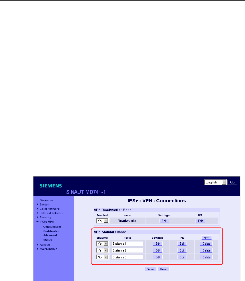
VPN connection
SINAUT MD741-1
76 C79000- G8976-C212
IPsec-SA lifetime (seconds) 86400
NAT-T On
Enable dead peer detection Yes
DPD - delay (seconds) 150
DPD – timeout (seconds) 60
DPD – maximum failures 5
7.2 VPN IPsec Standard Mode
The VPN connections already created are shown. You can enable (Enabled = Yes)
or disable (Enabled = No) each individual connection. You can use New to add
additional VPN connections, Edit Settings and Advanced Settings to set them up,
and Delete to remove a connection.
Figure 7-6 IPsec VPN > Connections
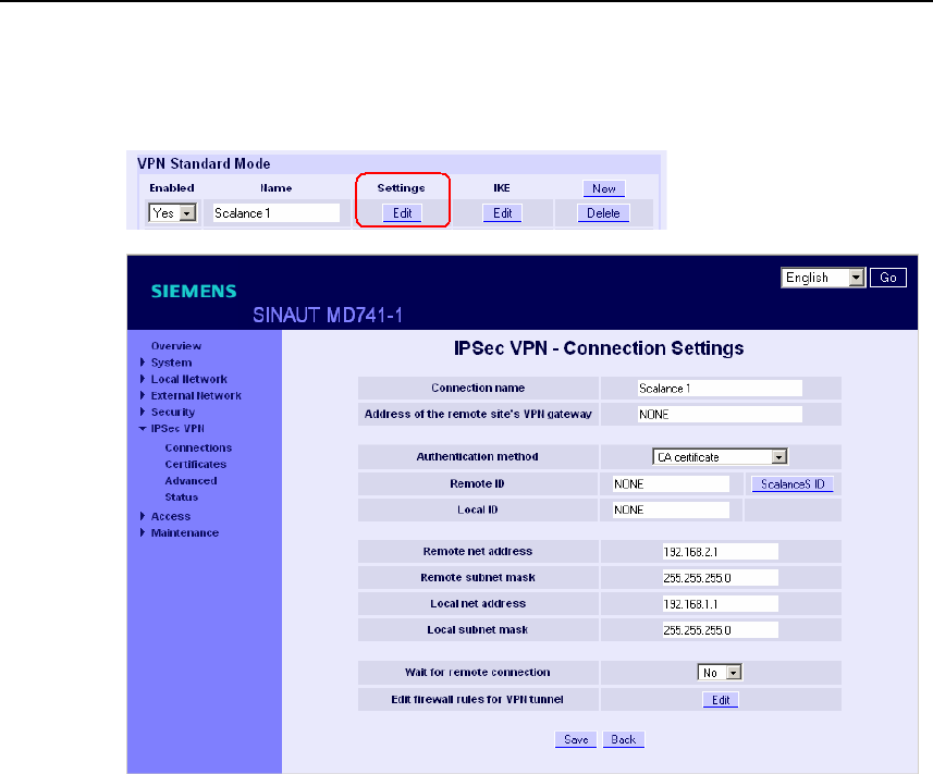
VPN connection
SINAUT MD741-1
C79000- G8976-C212 77
VPN Standard Mode - Edit Settings
Figure 7-7 IPsec VPN > Connection Settings
Connection name
Give the new connection a connection name here.
Remote host
Specify the address of the remote station here, either as a hostname (e.g.
myadress.com) or as an IP address.
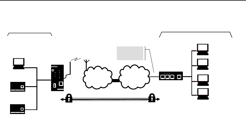
VPN connection
SINAUT MD741-1
78 C79000- G8976-C212
APN
(E-)GPRS INTERNET
MD741-1
VPN gateway
Local network Remote network
Local
application
Admin PC
Local
application
Admin PC
External
remote
stations
VPN tunnel
Address of
the remote
network
Figure 7-8 Address of the remote host
X.509 certificate, CA certificate
In the authentication methods X.509 certificate and CA certificate, the keys used
for authentication have first been signed by a Certification Authority (CA). This
method is considered especially secure. A CA can be a service provider, but also,
for example, the system administrator for your project, provided that he has the
necessary software tools. The CA creates a certificate file (PKCS12) with the file
extension *p12 for each of the two remote stations. This certificate file contains the
public and private keys for the own station, the signed certificate from the CA, and
the public key of the CA. For the authentication method X.509 there is additionally
a key file (*.pem, *cer or *.crt) for each of the two remote stations with the public
key of the own station.
X.509 certificate
The public keys (files with extension *.pem, *cer or *.crt) are exchanged between
the SINAUT MD741-1 and the remote station's VPN gateway takes place
manually, for example on a CD-ROM or vie e-mail. To load the certificate, proceed
as described in Chapter 7.3.
CA certificate
The public keys are exchanged between the SINAUT MD741-1 and the remote
station's VPN gateway via the data connection when the VPN connection is
established. Manual exchange of the key files is not necessary.
Pre-shared secret key (PSK)
This method is primarily supported by older IPsec implementations. Here
authentication is performed with a character string agreed on beforehand. In order
to obtain high security, the character string should consist of about randomly-
selected 30 lower-case and upper-case letters and numerals.

VPN connection
SINAUT MD741-1
C79000- G8976-C212 79
Remote ID, Local ID
The Local ID and the Remote ID are used by IPsec to identify the remote stations
uniquely when establishing the VPN connection.
For authentication with X.509 certificate or CA certificate:
● If you keep the factory setting NONE, then the Distinguished Names from the
own certificate and from the certificate communicated by the remote station are
automatically applied and used as the Local ID and Remote ID.
● If you manually change the entry for the Local ID or the Remote ID, then the
corresponding entries must be adapted at the remote station. The own Local ID
must be the same as the Remote ID of the remote station and vice versa. The
entries for Local or Remote IDs must be made in the ASN.1 format, e.g.
"C=XY/O=XY Org/CN=xy.org.org"
For authentication with pre-shared secret key (PSK):
● If you keep the factory setting NONE, then the own IP address is automatically
used as the Local ID, and the IP address of the remote station is used as the
Remote ID:
● If you manually change the entry for the Local ID or for the Remote ID, then the
entries must have the format of a hostname (e.g. RemoteStation.de) or the
format of an e-mail address (remote@station.de). The own Local ID must be
the same as the Remote ID of the remote station and vice versa.
Note:
If with pre-shared secret key (PSK) the IP address is not used as the Remote ID,
then the Aggressive Mode has to be set as the ISAKMP-SA mode.
Scalance S ID
If you have loaded a Scalance S certificate, by clicking the Scalance S button, you
can load the Remote ID from the certificate.
Wait for remote connection
Yes
The SINAUT MD741-1 waits for the VPN gateway of the remote network to initiate
establishment of the VPN connection.
No
The SINAUT MD741-1 initiates establishment of the connection.
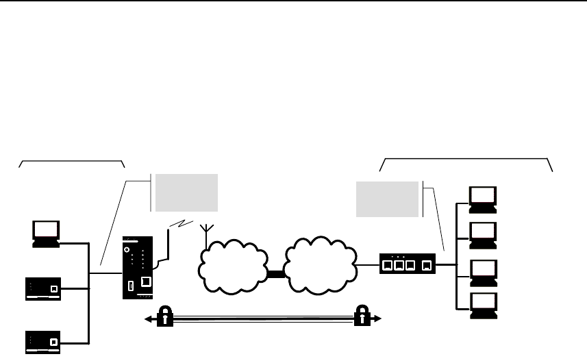
VPN connection
SINAUT MD741-1
80 C79000- G8976-C212
Remote net address
Here enter the IP address (e.g. 123.123.123.123) of the remote network. The
remote network can also be only a single computer.
APN
(E-)GPRS INTERNET
MD741-1
VPN gateway
Local network Gegenüberliegendes Netz
Local
application
Admin PC
Local
applikation
Admin PC
External
remote
stations
VPN tunnel
Address of
the remote
network
Address of
the local
network
Figure 7-9 Remote net address
Remote subnet mask
Here enter the subnet mask (e.g. 255.255.255.0) of the remote network. The
remote network can also be only a single computer.
Local net address
Here enter the IP address (e.g. 123.123.123.123) of the local network. The local
network can also be only a single computer.
Local subnet subnet mask
Here enter the subnet mask (e.g. 255.255.255.0) of the local network. The local
network can also be only a single computer.
Firewall rules for VPN tunnel
See Chapter 7.4
VPN Standard Mode - Edit IKE
Here you can define the properties of the VPN connection according to your
requirements and what you have agreed with the system administrator of the
remote station.
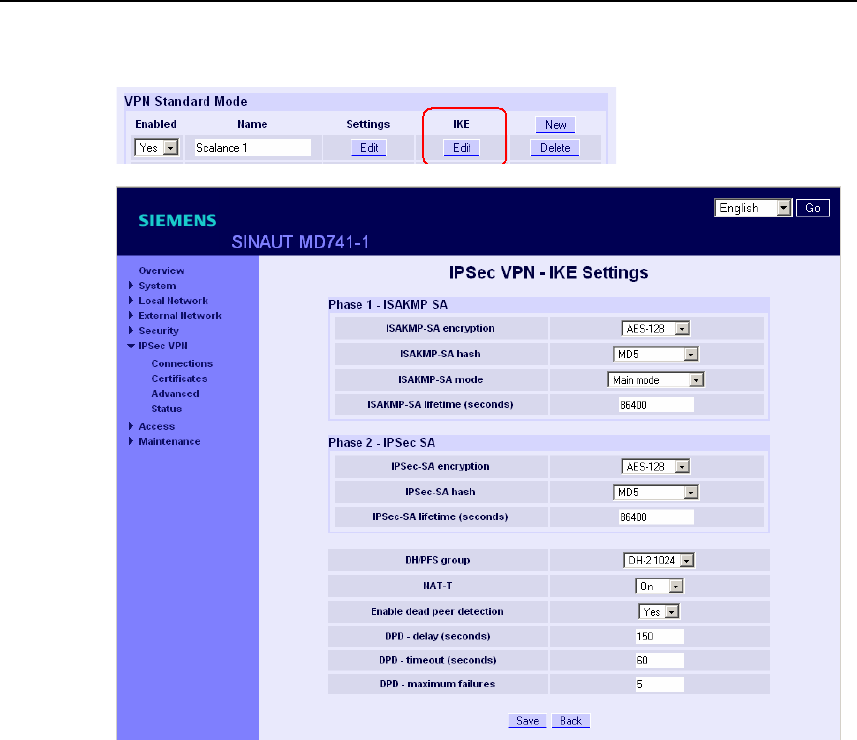
VPN connection
SINAUT MD741-1
C79000- G8976-C212 81
Figure 7-10 IPsec > IKE Settings
ISAKMP-SA encryption, IPsec-SA encryption
Agree with the administrator of the remote station which encryption method will be
used for the ISAKMP-SA and the IPsec-SA. The SINAUT MD741-1 supports the
following methods:
● 3DES-168
● AES-128
● AES-192
● AES-256
3DES-168 is a commonly used, and is therefore set as the default. The method
can be defined differently for ISAKMP-SA and IPsec-SA.

VPN connection
SINAUT MD741-1
82 C79000- G8976-C212
Note:
The more bits in the encryption algorithm - indicated by the appended number - the
more secure it is. The method AES-256 is therefore considered the most secure.
However, the longer the key, the more time the encryption process takes and the
more computing power is required.
ISAKMP-SA hash, IPsec-SA hash
Agree with the administrator of the remote station which method will be used for
computing checksums/hashes during the ISAKMP phase and the IPsec phase. The
following selections are available:
● MD5 or SHA-1 (automatic detection)
● MD5
● SHA-1
The method can be defined differently for ISAKMP-SA and IPsec-SA.
ISAKMP-SA mode
Agree with the administrator of the remote station which method will be used for
negotiating the ISAKMP-SA. The following selections are available:
● Main mode
● Aggressive mode
DH/PFS group
Agree with the administrator of the remote station the DH group for the key
exchange.
ISAKMP-SA lifetime, IPsec-SA lifetime
The keys for an IPsec connection are renewed at certain intervals in order to
increase the effort required to attack an IPsec connection.
Specify the lifetime (in seconds) of the keys agreed on for the ISAKMP-SA and
IPsec-SA.
The lifetime can be defined differently for ISAKMP-SA and IPsec-SA.

VPN connection
SINAUT MD741-1
C79000- G8976-C212 83
NAT-T
There may be a NAT router between the SINAUT MD741-1 and the VPN gateway
of the remote network. Not all NAT routers allow IPsec data packets to go through.
It may therefore be necessary to encapsulate the IPsec data packets in UDP
packets so that they can go through the NAT router.
On:
If the SINAUT MD741-1 detects a NAT router that does not let the IPsec data
packets through, then UDP encapsulation is started automatically.
Force:
During negotiation of the connection parameters for the VPN connection,
encapsulated transmission of the data packets during the connection is insisted
upon.
Off:
The NAT-T function is switched off.
Enable dead peer detection
If the remote station supports the dead peer detection (DPD) protocol, then the
partner in question can detect whether the IPsec connection is still valid or not,
meaning that it may have to be re-established. Without DPD, depending on the
configuration it may be necessary to wait until the SA lifetime elapses or the
connection has to be re-initiated manually. To check whether the IPsec connection
is still valid, the dead peer detection sends DPD requests to the remote station
itself. If there is no answer, then after the permitted number of failed attempts the
IPsec connection is considered to be interrupted.
Yes
Dead peer detection is switched on. Attempts are made to re-establish the IPsec
connection if it has been declared dead, independently of the transmission of user
data.
No
Dead peer detection is switched off.
DPD - delay (seconds)
Time period in seconds after which DPD requests will be sent. These requests test
whether the remote station is still available.

VPN connection
SINAUT MD741-1
84 C79000- G8976-C212
DPD - timeout (seconds)
Time period in seconds after which the connection to the remote station will be
declared dead if no response has been made to the DPD requests.
DPD – maximum failures
Number of failed attempts permitted before the IPsec connection is considered to
be interrupted.
Factory setting
The factory settings for the SINAUT MD741-1 are as follows:
Name NewConnection
Enabled No (switched off)
Authentication method CA certificate
Remote ID NONE
Local ID NONE
Remote certificate -
Wait for remote connection No
Remote net address 192.168.2.1
Remote subnet mask 255.255.255.0
Local net address 192.168.1.1
Local subnet subnet mask 255.255.255.0
ISAKMP-SA encryption 3DES-168
IPsec-SA encryption 3DES-168
ISAKMP-SA hash MD5
IPsec-SA hash MD5
DH/PFS group DH-2 1024
ISAKMP-SA mode Main
ISAKMP-SA lifetime (seconds) 86400
IPsec-SA lifetime (seconds) 86400
NAT-T On
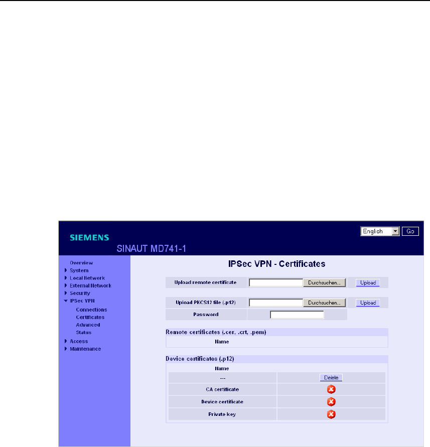
VPN connection
SINAUT MD741-1
C79000- G8976-C212 85
Enable dead peer detection Yes
DPD - delay (seconds) 150
DPD – timeout (seconds) 60
DPD – maximum failures 5
7.3 Loading VPN certificates
Loading and administering certificates and keys.
Figure 7-11 IPsec > Certificates
Upload remote certificate
Here load key files (*.pem, *.cer or *.crt) with remote certificates and public key
from remote stations into the SINAUT MD741-1. To do this, the files must be saved
on the Admin PC. A remote certificate is only required for the authentication
method with X.509 certificate.
Upload PKCS12 file (.p12)
Here load the certificate file (PKCS12 file) with the file extension .p12 into the
SINAUT MD741-1. To do this, the certificate file must be saved on the Admin PC.

VPN connection
SINAUT MD741-1
86 C79000- G8976-C212
Caution
If there is already a certificate file in the device, then it must be deleted before
loading a new file.
Password
The certificate file (PKCS12 file) is password-protected. Here enter the password
that you received with the certificate file.
Remote certificates (*.pem, *cer, .crt,)
A list with all of the loaded remote certificates is shown here. You can use Delete to
remove a remote certificates that is no longer needed.
Device certificates (.p12)
The name and status of the loaded certificate file (PKCS12 file) is shown here. A
white check mark on a green dot indicates that the corresponding component of
the certificate file is present, a white cross on a red dot indicates that the
corresponding component is missing or that the wrong password was entered.
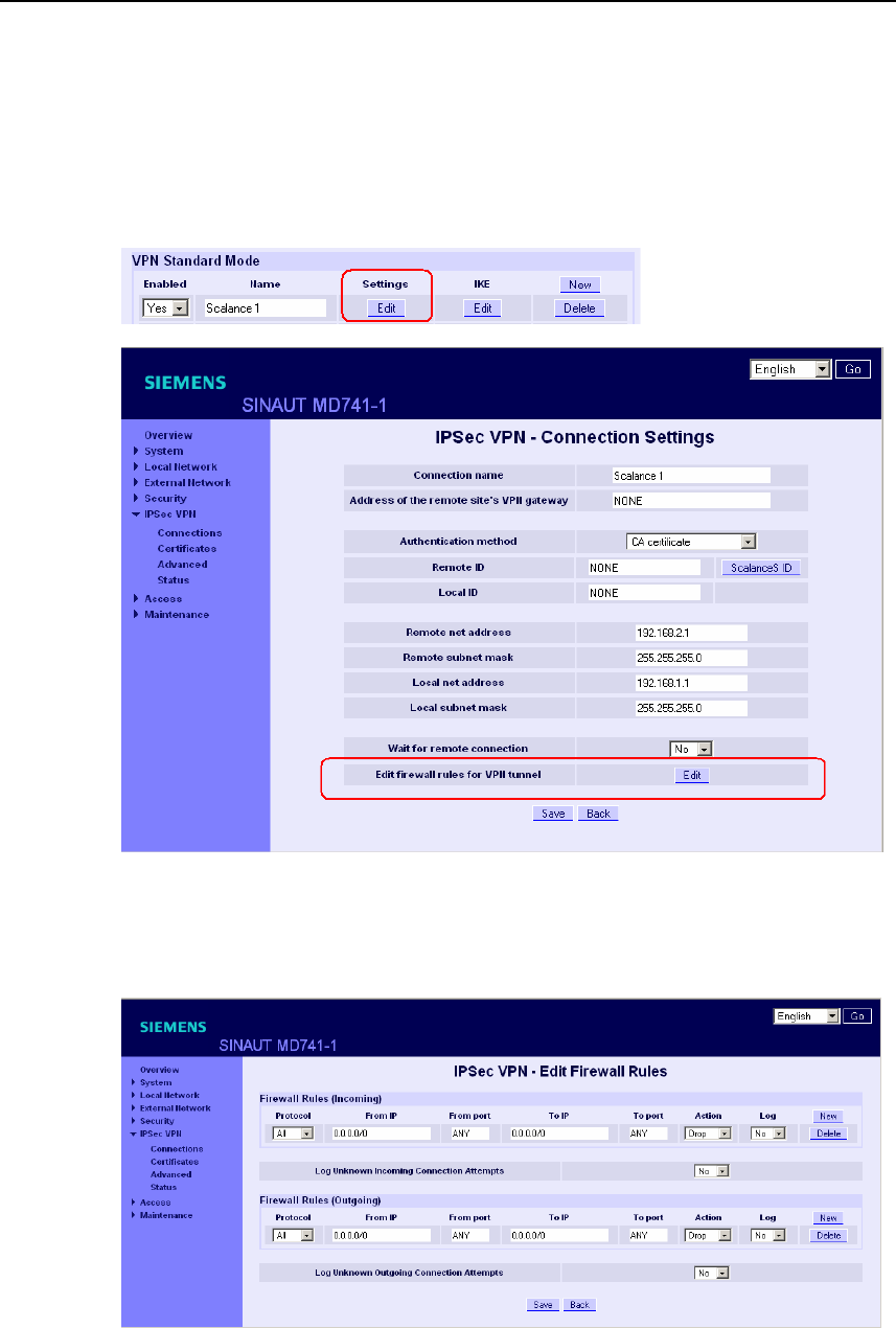
VPN connection
SINAUT MD741-1
C79000- G8976-C212 87
7.4 Firewall rules for VPN tunnel
The user interface for setting up the firewall rules for VPN tunnels can be found
under IPsec VPN > Connections:
Figure 7-12 IPsec > Connection Settings
IPsec VPN – Edit Firewall Rules
Figure 7-13 IPsec > Edit Firewall Rules
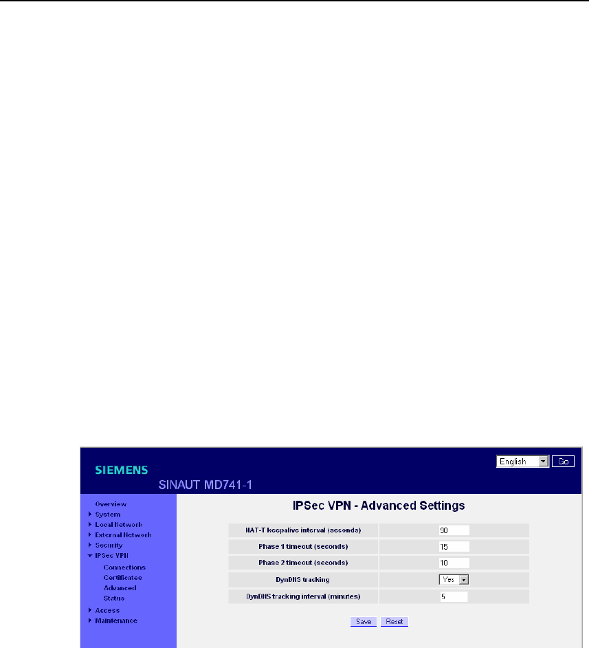
VPN connection
SINAUT MD741-1
88 C79000- G8976-C212
Function
The IPsec VPN connection is viewed as fundamentally secure. Thus data traffic
over this connection is not limited by default. It is possible, however, to create
firewall rules for the VPN connection
To set up firewall rules for the VPN connection, proceed in the same way as for
setting up the packet filter function of the general firewall (see Chapter 6.1).
However, the rules defined here apply only to the specific VPN connection.
Factory setting
The factory settings for the SINAUT MD741-1 are as follows:
Firewall rules for VPN tunnel No limitations
7.5 Advanced settings for VPN connections
Setting special timeouts and intervals for VPN connections.
Figure 7-14 IPsec > Advanced Settings
NAT-T keepalive interval (seconds)
If NAT-T is enabled (cf. Chapter 7.2), then keepalive data packets will be sent
periodically by the SINAUT MD741-1 through the VPN connection. The purpose of
this is to prevent a NAT router between the SINAUT MD741-1 and the remote
station from interrupting the connection during idle periods without data traffic.
Here you can change the interval between the keepalive data packets.

VPN connection
SINAUT MD741-1
C79000- G8976-C212 89
Phase 1 timeout (seconds)
The Phase 1 timeout determines how long the SINAUT MD741-1 waits for
completion of an authentication process of the ISAKMP-SA. If the set timeout is
exceeded, the authentication will be aborted and restarted.
Here you change the timeout.
Phase 2 timeout (seconds)
The Phase 2 timeout determines how long the SINAUT MD741-1 waits for
completion of an authentication process of the IPsec-SA. If the set timeout is
exceeded, the authentication will be aborted and restarted.
Here you change the timeout.
DynDNS tracking
If the VPN gateway of the remote stations uses a DynDNS service to get an IP
address and no Dead Peer Detection is used, the SINAUT MD741-1 should
periodically check, if the remote VPN gateway is still reachable. The DynDNS
tracking function provides this function. Yes activates this function, No deactivate
this function.
DynDNS tracking interval (minutes)
Configure here the interval it shall be checked, if the remote station is still
reachable.
Factory setting
The factory settings for the SINAUT MD741-1 are as follows:
NAT-T keepalive interval (seconds) 60
Phase 1 timeout (seconds) 15
Phase 2 timeout (seconds) 10
DynDNS tracking Yes
DynDNS tracking interval (minutes) 5
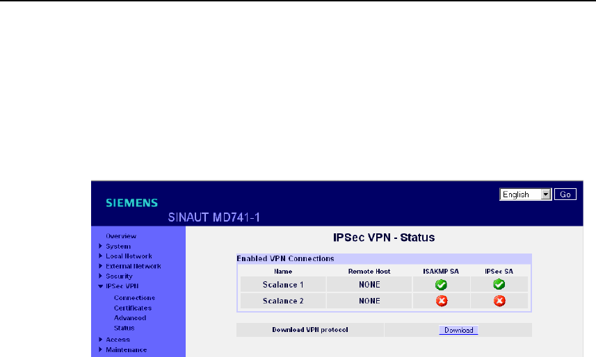
VPN connection
SINAUT MD741-1
90 C79000- G8976-C212
7.6 Status of the VPN connections
Indicates the status of the enabled VPN connections and the option for loading a
protocol file to the Admin PC.
Figure 7-15 IPsec > Status
Enabled VPN Connections
A white check mark on a green dot indicates that the specific Security Association
(SA) has been successfully established- A white cross on a red dot indicates that
the Security Association does not exist.
Download VPN protocol
This function can be used to download the VPN protocol file to the Admin PC.
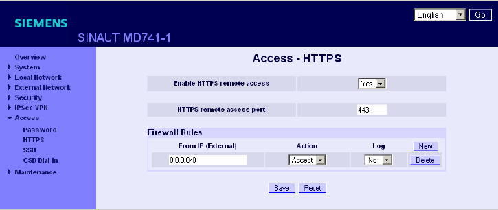
SINAUT MD741-1
91 C79000- G8976-C212
Remote access 8
8.1 HTTPS remote access
The HTTPS remote access (= HyperText Transfer Protocol Secure) allows secure
access to the Web user interface of the SINAUT MD741-1 from an external
network via EGPRS, GPRS or CSD.
Configuration of the SINAUT MD741-1 via the HTTPS remote access then takes
place exactly like configuration via a Web browser via the local interface (see
chapter 3).
Figure 8-1 Access > HTTPS remote access
Enable HTTPS remote access
Yes
Access to the Web user interface of the SINAUT MD741-1 from the external
network via HTTPS is allowed.
No
Access via HTTPS is not allowed.

Remote access
SINAUT MD741-1
92 C79000- G8976-C212
HTTPS remote access port
Default: 443 (factory setting)
You can define a different port. However, if you have defined a different port, then
the external remote station conducting the remote access must specify the port
number after the IP address when specifying the address.
Example:
If this SINAUT MD741-1 can be accessed via the Internet using the address
192.144.112.5, and if port number 442 has been defined for the remote access,
then the following must be specified in the Web browser at the external remote
station:
https://192.144.112.5:442
Firewall rules for HTTPS remote access
New
Adds a new firewall rule for HTTPS remote access that you can then fill out.
Delete
Removes a firewall rule for HTTPS remote access that has been created.
From IP (External)
Specify here the address(es) of the computer(s) for which remote access is
allowed. You have the following options:
IP address or address range: 0.0.0.0/0 means all addresses. To specify a range,
use the CIDR notation - see the Glossary.
Action
Define how access to the specified HTTPS port will be handled:
Accept means that the data packets can go through.
Reject means that the data packets are rejected, and the sender receives a
message about the rejection.
Drop means that the data packets are not allowed through. They are discarded
without the sender receiving any information about where they went.
Log
For each individual firewall rule you can define whether the event should be logged
when the rule takes effect - set Log toYes, or not - set Log to No (factory setting).
The log is kept in the firewall log, see Chapter 6.4.
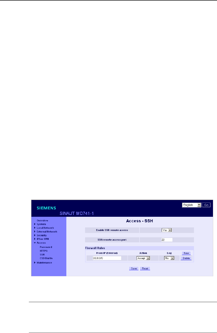
Remote access
SINAUT MD741-1
C79000- G8976-C212 93
Factory setting
The factory settings for the SINAUT MD741-1 are as follows:
Enable HTTPS remote access No (switched off)
HTTPS remote access port 443
Default for new rules:
From IP (External) 0.0.0.0/0
Action Accept
Log No (switched off)
8.2 SSH remote access
The SSH remote access (= Secured SHell) allows secure access to the file system
of the SINAUT MD741-1 from an external network via EGPRS, GPRS or CSD.
To do this, a connection must be established using an SSH-capable program from
the external remote station to the SINAUT MD741-1.
Use the SSH remote access only if you are familiar with the LINUX file system.
In the factory setting this option is deactivated.
Figure 8-2 Access >SSH remote access
Warning
Via SSH remote access it is possible to derange the configuration of the device in
such a way that it will have to be sent in for servicing. In this case contact your
dealer or distributor.

Remote access
SINAUT MD741-1
94 C79000- G8976-C212
Enable SSH remote access
Yes
Access to the file system of the SINAUT MD741-1 from the external network via
SSH is allowed.
No
Access via SSH is not allowed.
SSH remote access port
Default: 22 (factory setting)
You can define a different port. However, if you have defined a different port, then
the external remote station conducting the remote access must specify the port
number defined here in front of the IP address when specifying the address.
Example:
If this SINAUT MD741-1 can be accessed from the external network using the
address 192.144.112.5, and if port 22222 has been defined for the remote access,
then this port number must be specified in the SSH client (e.g. PUTTY) at the
external remote station:
ssh -p 22222 192.144.112.5
Firewall rules for SSH remote access
New
Adds a new firewall rule for SSH remote access that you can then fill out.
Delete
Removes a firewall rule for SSH remote access that has been created.
From IP (External)
Specify here the address(es) of the computer(s) for which remote access is
allowed. You have the following options:
IP address or address range: 0.0.0.0/0 means all addresses. To specify a range,
use the CIDR notation - see the Glossary.
Action
Define how access to the specified SSH port will be handled:
Accept means that the data packets can go through.

Remote access
SINAUT MD741-1
C79000- G8976-C212 95
Reject means that the data packets are rejected, and the sender receives a
message about the rejection.
Drop means that the data packets are not allowed through. They are discarded
without the sender receiving any information about where they went.
Log
For each individual firewall rule you can define whether the event should be logged
when the rule takes effect - set Log to Yes, or not - set Log to No (factory setting).
The log is kept in the firewall log, see Chapter 6.4.
Factory setting
The factory settings for the SINAUT MD741-1 are as follows:
Enable SSH remote access No (switched off)
HTTPS remote access port 22
Default for new rules:
From IP (External) 0.0.0.0/0
Action Accept
Log No (switched off)
8.3 Remote access via dial-in connection
The CSD dial-in access makes it possible to access the Web user interface of the
SINAUT MD741-1 via a dial-in data connection (CSD = Circuit Switched Data). To
do this, call the SINAUT MD741-1 at the data call number using an analogue
modem, or at the voice or data call number of its SIM card using a GSM modem.
The SINAUT MD741-1 accepts the call if:
● the call number of the telephone connection that you call from is saved in the
list of permitted numbers in SINAUT MD741-1, and
● the call number is transmitted by the telephone network (CLIP function)
Dialling must be performed by a PPP client, for example via a Windows dial-up
connection. In Windows, use the New Connection Wizard, and under Connect to
the network at my workplace set up a Dial-up connection.
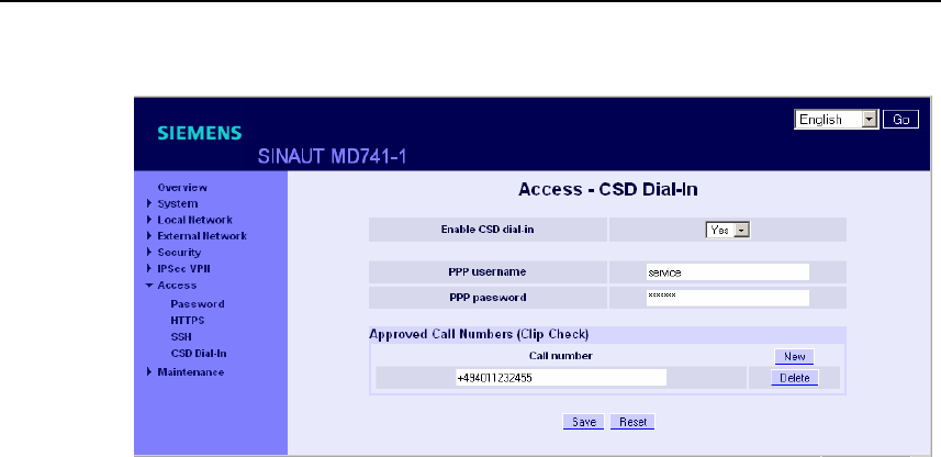
Remote access
SINAUT MD741-1
96 C79000- G8976-C212
Figure 8-3 Access > CSD Dial-In
Enable CSD dial-in
Yes
Access to the Web user interface of the SINAUT MD741-1 from a dial-in data
connection is allowed.
No
Access via dial-in data connection is not allowed.
PPP username / password
Select a username and a password that must be used by a PPP client (e.g. a
Windows dial-up connection) to log on to the SINAUT MD741-1. The same
username and the same password must be entered in the PPP client.
Approved Call Numbers
Specify the call number of the telephone connection from which the dial-in data
connection is established. The telephone connection must support Calling Line
Identification Presentation (CLIP), and this function must be activated.
The call number entered in the SINAUT MD741-1 must be exactly the same as the
call number reported, any may also have to include the country code and prefix,
e.g. +494012345678.
If multiple call numbers of a private branch exchange are to have access
authorisation, you can use the "*" symbol as a wildcard, e.g. +49401234*. Then all
call numbers that begin with +49401234 will be accepted.

Remote access
SINAUT MD741-1
C79000- G8976-C212 97
Note
Firewall rules entered for HTTPS and SSH access also apply for CSD access. The
source IP address ("From IP") for CSD access is defined as 10.99.99.2.
New
Adds a new approved call number for CSD remote access that you can then fill out.
Delete
Removes a firewall rule for CSD remote access.
Factory setting
The factory settings for the SINAUT MD741-1 are as follows:
Enable CSD dial-in No (switched off)
PPP username service
PPP password service
Approved Call Numbers *

Remote access
SINAUT MD741-1
98 C79000- G8976-C212
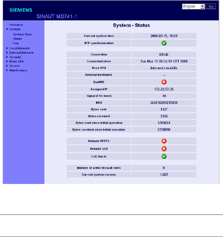
SINAUT MD741-1
99 C79000- G8976-C212
Status, log and diagnosis 9
9.1 System status display
The System-Status gives an overview about the current operating status of the
SINAUT MD741-1.
Figure 9-1 System > Status
Note
Use the Refresh function of the Web browser to update the displayed values.

Status, log and diagnosis
SINAUT MD741-1
100 C79000- G8976-C212
Current system time
Shows the current system time of the SINAUT MD741-1 in the format:
Year – Month – Day, Hours – Minutes
Connection
Shows if a wireless connection exists, and which one:
● EDGE connection (IP connection via EGPRS)
● GPRS connection (IP connection via GPRS)
● CSD connection (service connection via CSD)
Note
It may occur that an EDGE (EGPRS) or GPRS connection and an assigned IP
address are both shown, but the connection quality is still not good enough to
transmit data. For this reason we recommend using the active connection
monitoring (see Chapter 5.2).
Connected since
Shows how long the current connection to EGPRS or GPRS has existed.
Used APN
Shows the APN (= Access Point Name) of the EGPRS or GPRS that is being used.
External hostname
Shows the hostname (e.g. md741-1.mydns.org) of the SINAUT MD741-1, if a
DynDNS service is being used.
DynDNS
Shows if a DynDNS service is activated.
● White check mark at green dot: DynDNS service activated.
● White cross at red dot: DynDNS service not activated

Status, log and diagnosis
SINAUT MD741-1
C79000- G8976-C212 101
Assigned IP address
Shoes the IP address at which the SINAUT MD741-1 can be reached in EGPRS or
GPRS. This IP address is assigned to the SINAUT MD741-1 by the EGPRS or
GPRS service.
Signal (CSQ level)
Indicates the strength of the GSM signal as a CSQ value.
● CSQ < 6: Poor signal strength
● CSQ= 6..10: Medium signal strength
● CSQ=11-18: Good field strength
● CSQ > 18: Very good field strength
● CSQ = 99: No connection to the GSM network
IMSI
Shows the subscriber identity that is saved on the SIM card being used.
The IMSI (= International Mobile Subscriber Identity) is used by the GSM network
operator to detect the authorisations and agreed services for the SIM card.
IMEI
Shows the serial number of the SINAUT MD741-1 as a GSM wireless device. The
IMEI (= International Mobile Equipment Identity) is assign uniquely worldwide.
Bytes sent / Bytes received
Shows the number of bytes that have been sent or received during the existing
connection to GPRS. The counter is reset when a new connection is established.
Note
These figures serve only as a general indication of the data volume, and can differ
significantly from the GSM network operator's accounting.

Status, log and diagnosis
SINAUT MD741-1
102 C79000- G8976-C212
Bytes sent / Bytes received since initial operation
Shows the number of bytes that have been sent via GPRS or received since the
last time the factory settings were loaded. The counter is reset when the factory
settings are loaded.
Remote HTTPS
Shows whether remote access to the Web user interface of the SINAUT MD741-1
via EGPRS or GPRS is permitted.
● White check mark at green dot: Access is allowed.
● White cross at red dot: Access is not allowed.
Remote SSH
Shows whether remote access to the SSH console of the SINAUT MD741-1 via
EGPRS or GPRS is permitted.
● White check mark at green dot: Access is allowed.
● White cross at red dot: Access is not allowed.
CSD Dial-In
Shows whether remote CSD service calls are allowed.
● White check mark at green dot: CSD service calls are possible.
● White cross at red dot: CSD service calls are not possible.
Number of active firewall rules
Shows how many firewall rules are active.
Current system version
Shows the version number of the SINAUT MD741-1's software.
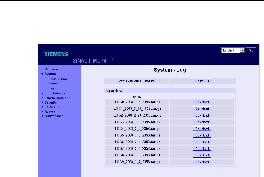
Status, log and diagnosis
SINAUT MD741-1
C79000- G8976-C212 103
9.2 Log
Figure 9-2 System > Log
Logfile
Important events in the operation of the SINAUT MD741-1 are saved in the log.
● Reboot
● Changes to the configuration
● Establishing of connections
● Interruption of connections
● Signal strength
● and operating messages
The log is saved to the log archive of the SINAUT MD741-1 when a file size
1 MByte, is reached, but after 24 hours at the latest.
Download current logfile
Download - the current log is loaded to the Admin PC. You can select the directory
to save the file to, and can view the file there.
Download - The archived log files are loaded to the Admin PC. You can select the
directory to save the files to, and can view the files there.
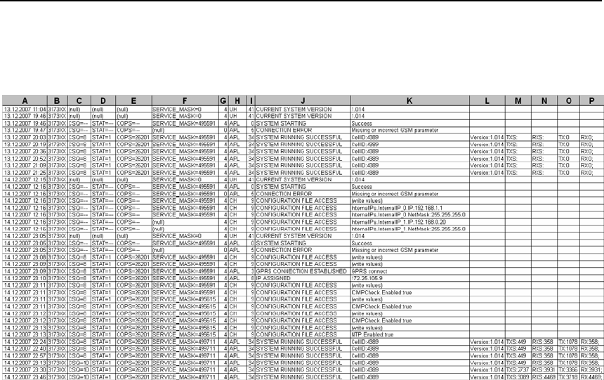
Status, log and diagnosis
SINAUT MD741-1
104 C79000- G8976-C212
Example:
Entries in log
Column A:
Time stamp
Column B:
Product number
Column C:
Signal quality (CSQ value)
Column D:
GSM login status
STAT = --- = Function not activated yet
STAT = 1 = Logged in to home network
STAT = 2 = Not logged in; searching for network
STAT = 3 = Login rejected
STAT = 5 = Logged in to third-party network (roaming)
Column E:
Indication of the network operator identification with the 3-digit country code (MCC)
and the 2-3-digit network operator code (MNC).

Status, log and diagnosis
SINAUT MD741-1
C79000- G8976-C212 105
Example: 26201 (262 = country code / 01 = network operator code)
Column F:
Coded operating status (for Hotline)
Column G:
Category of the log report (for Hotline)
Column H:
Internal source of the log report (for Hotline)
Column I:
Internal report number (for Hotline)
Column J:
Log report in plain text
Columns K-P:
Additional information on the plain text report, such as:
● Cell ID (identification number of the active GSM cell)
● Software version
● TXS, RXS (IP packets transmitted in the current connection)
● TX, RX (IP packets transmitted since the last factory settings reboot)
9.3 Remote logging
The SINAUT MD741-1 can transfer the system log once per day via FTP (= File
Transfer Protocol) to an FTP server.
The current system log and the system log files in the archive are transferred. After
successful transfer the transferred logs are deleted in the SINAUT MD741-1.
If the transfer fails, the SINAUT MD741-1 tries once again to transfer the data after
24 hours.
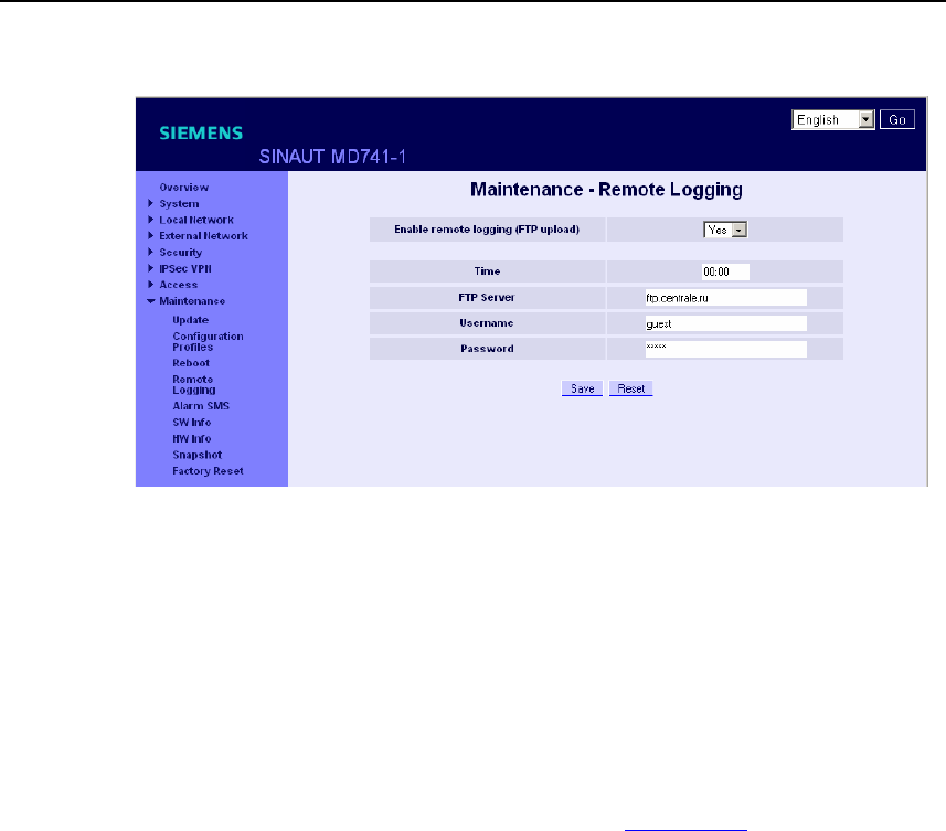
Status, log and diagnosis
SINAUT MD741-1
106 C79000- G8976-C212
Figure 9-3 Maintenance > Remote Logging
Enable remote logging (FTP upload)
Yes activates the function.
Time
Specifies the address of the FTP server to which the log files are to be transferred.
The address can be specified as a hostname (e.g. ftp.server.de) or as an IP
address.
Username
Specifies the username for logging in to the FTP server.
Password
Specifies the password for logging in to the FTP server.
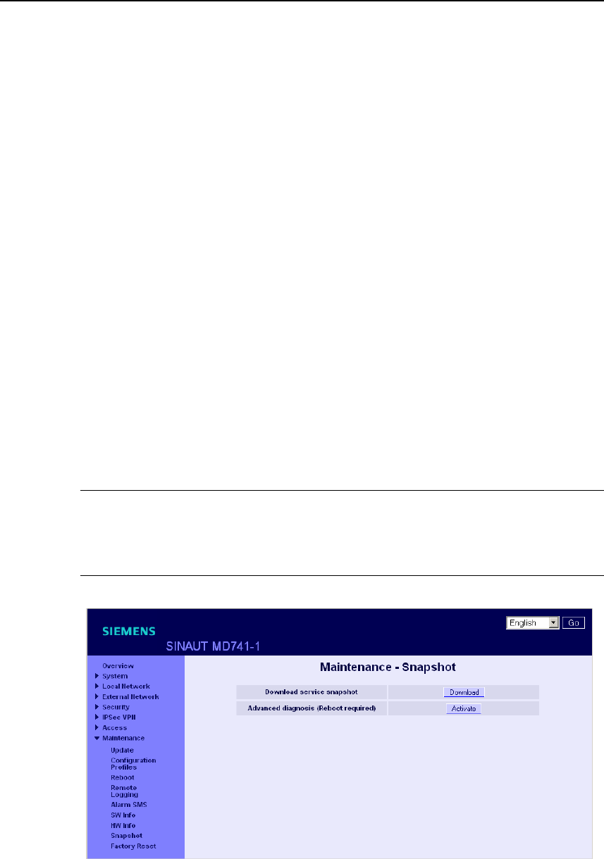
Status, log and diagnosis
SINAUT MD741-1
C79000- G8976-C212 107
Factory setting
The factory settings for the SINAUT MD741-1 are as follows:
Enable remote logging (FTP upload) No (switched off)
Time 00:00
FTP Server NONE
Username guest
Password guest
9.4 Snapshot
This function is used for support purposes.
The service snapshot downloads important log files and current device settings that
could be important for fault diagnosis and saves them in a file.
If you contact our Hotline in the event of a problem with the SINAUT MD741-1, in
many cases they will ask you for the snapshot file.
Note
This file contains the access parameters for EGPRS and GPRS and the addresses
of the remote station. It does not contain the username and password for access to
the SINAUT MD741-1.
Figure 9-4 Maintenance > Snapshot
This function is used for support purposes.

Status, log and diagnosis
SINAUT MD741-1
108 C79000- G8976-C212
The service snapshot downloads important log files and current device settings that
could be important for fault diagnosis and saves them in a file.
If you contact our Hotline in the event of a problem with the SINAUT MD741-1, in
many cases they will ask you for the snapshot file.
Note
This file contains the access parameters for EGPRS and GPRS and the addresses
of the remote station. It does not contain the username and password for access to
the SINAUT MD741-1.
Download service snapshot
Click on download. You can select the location on the Admin PC where the
snapshot file will be saved.
The filename of the snapshot file has the following structure:
<hostname>_Snapshot_<Date&TimeCode>.tgz,
e.g.: md741_Snapshot_200711252237.tgz
Advanced diagnosis
Only Activate the Advanced diagnosis if asked to do so by our Hotline. In operation
with advanced diagnosis, information is written to the diagnosis logs much more
often. Some additional information is also saved. This is useful for systematic
troubleshooting.
Note
When advanced diagnosis is active, the frequent write access to the non-volatile
memory of the SINAUT MD741-1 can lead to a reduction of its service life.
Factory setting
The factory settings for the SINAUT MD741-1 are as follows:
Advanced diagnosis Off (Activate)
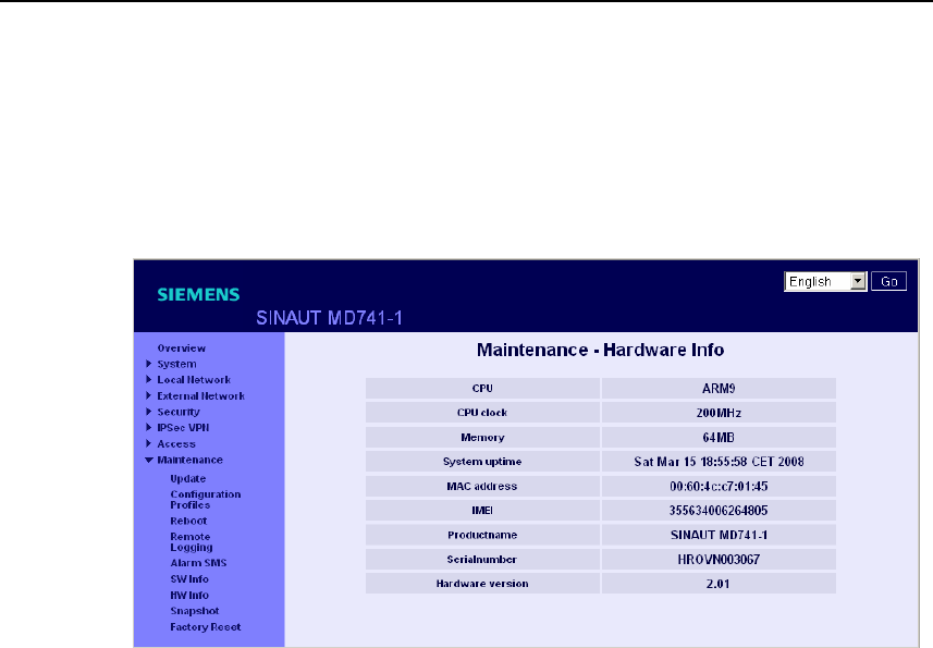
Status, log and diagnosis
SINAUT MD741-1
C79000- G8976-C212 109
9.5 Hardware information
Shows important information for hardware identification. This information is often
needed in the event of queries to our Hotline.
Figure 9-5 Maintenance > Hardware info
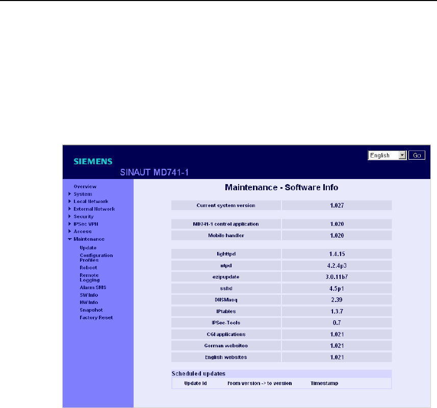
Status, log and diagnosis
SINAUT MD741-1
110 C79000- G8976-C212
9.6 Software information
Shows important information for software identification. This information is often
needed in the event of queries to our Hotline.
Planned updates are additionally shown. See also Chapter 10.2.
Figure 9-6 Maintenance > Software info
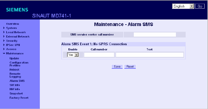
SINAUT MD741-1
111 C79000- G8976-C212
Additional functions 10
10.1 Alarm SMS
The SINAUT MD741-1 can transmit short alarm messages via the SMS
(= Short Message Service) of the GSM network. Two events can trigger
transmission of an alarm message via SMS:
● Event 1: No GPRS connection
A separate call number for sending the alarm message to can be specified for each
of these two events. The text of the alarm message can also be freely defined. The
following characters are available: A-Z a-z 0123456789,!?
Figure 10-1 Maintenance > Alarm SMS
Alarm SMS Event 1: No GPRS Connection In Port
The GPRS connection is not established despite multiple attempts. The SINAUT
MD741-1 then transmits an alarm message.

Additional functions
SINAUT MD741-1
112 C79000- G8976-C212
SMS service center call number
So that the SMS function will function reliably, enter the call number of the service
center here. Without an entry in this location the default SMS service center of your
network operator will be used.
Settings
Enable
With Yes the alarm message is sent when the event occurs, with No it is not.
Call number
Here enter the call number of the end device to which the alarm message is to be
sent via SMS. The end device must support SMS reception via GSM or fixed
network.
Text
Here enter the text that should be sent as an alarm message.
Factory setting
The factory settings for the SINAUT MD741-1 are as follows:
SMS service center call number -
Alarm SMS Event 1: No GPRS No (switched off)
Call number -
Text -
10.2 Software Update
The Update function can be used to load new operating software to the SINAUT
MD741-1 and activate this software.
In an immediate update the new software will be unzipped. This process can take
several minutes. After that the actual update process begins, which is indicated by
the LEDs lighting up in sequence.
The settings of the SINAUT MD741-1 will be accepted insofar as the settings still
have the same effect in the new software version as they did before the update.
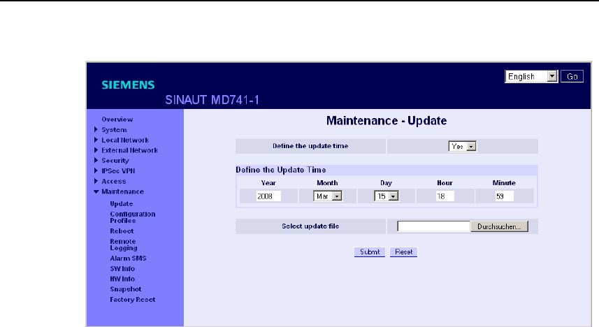
Additional functions
SINAUT MD741-1
C79000- G8976-C212 113
Figure 10-2 Maintenance > Update
Define the update time
No
Immediate update - The new operating software is activated immediately after you
load the software and click on Submit.
Yes
Time-controlled update - The new operating software is activated at the defined
update time. The software must have been loaded already.
Define the update time
If you want to have the update carried out with time control, specify the time when
the new operating software is to be activated.
Specify the Year – Month – Day – Hour – Minute.
Select update file
Use Browse to select the file, which includes the new operating software, for
example:
MD741_v1.024-v1.027.tgz
Load the firmware to the device with Open.

Additional functions
SINAUT MD741-1
114 C79000- G8976-C212
Submit
With Submit the operating software is either activated immediately or the operating
software is activated at the specified time.

SINAUT MD741-1
C79000- G8976-C212 115
Technical Data 11
Interfaces Application
interface
10/100 Base-T (RJ45 plug)
Ethernet IEEE802
10/100 Mbit/s
Service interface USB-A (reserved for later applications)
Security
functions Stateful inspection firewall
Anti-spoofing
Port forwarding
Additional
functions DNS cache, DHCP server, NTP, remote logging,
connection monitoring, alarm-SMS
Management Web-based administration user interface, ssh console
Wireless
connection EDGE / GPRS EDGE Multislot class 12 / EDGE Multislot class 12
Coding schemes CS-1, CS-2, CS-3, CS-4
GSM Module EGPRS (EDGE) / Quad band
EDGE (EGPRS) Multislot Class 12
Mobile Station Class B
Modulation and Coding Scheme MCS 1 – 9
GPRS Multislot Class 12
Full PBCCH support
Mobile Station Class B
Coding Scheme 1 – 4
EDGE / GPRS During the data transmission via EGPRS or GPRS the
device automatically selects from the following
classes:
from EGPRS Multislot Class 12 (4Tx slots)
to EGPRS Multislot Class 10 (2Tx slots),
from EGPRS Multislot Class 10 (2Tx slots)
to EGPRS Multislot Class 8 (1Tx),
from GPRS Multislot Class 12 (4Tx slots)
to GPRS Multislot Class 8 (1Tx)
from GPRS Multislot Class 10 (2Tx slots)
to GPRS Multislot Class 8 (1Tx)
CSD / MTC V.110, RLP, non-transparent
2.4, 4.8, 9.6, 14.4kbps
SMS (TX) Point to point, MO (outgoing)
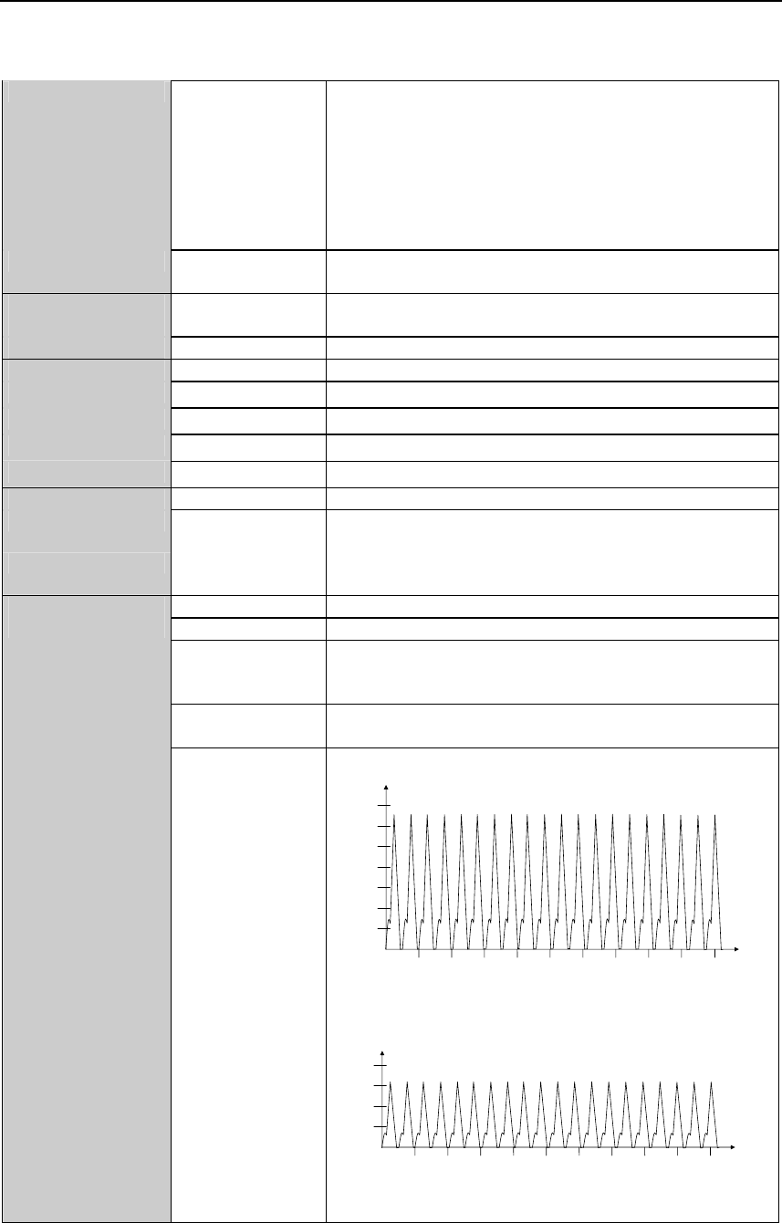
Technical Data
SINAUT MD741-1
116 C79000- G8976-C212
Max. transmitting
power (acc. to
output 99, V5)
Class 4 (+33dBm ±2dB) for EGSM850
Class 4 (+33dBm ±2dB) for EGSM900
Class 1 (+30dBm ±2dB) for GSM1800
Class 1 (+30dBm ±2dB) for GSM1900
Class E2 (+27dBm ± 3dB) for GSM 850 8-PSK
Class E2 (+27dBm ± 3dB) for GSM 900 8-PSK
Class E2 (+26dBm +3 /-4dB) for GSM 1800 8-PSK
Class E2 (+26dBm +3 /-4dB) for GSM 1900 8-PSK
Antenna
connection
Nominal impedance: 50 ohms, jack: SMA
Ambient
conditions Temperature
range
Operation: -20 °C to +60 °C
Storage: -40 °C to +70 °C
Air humidity 0-95 %, non-condensing
Housing Design Top-hat rail housing
Material Plastic
Protection class IP20
Dimensions 114 mm x 45 mm x 99 mm
Weight approx. 280g
DE CE Yes
GSM/EGPRS
module
Conforms to GCF, PTCRB
Environment The device complies with the European Directives
RoHS and WEEE.
Input voltage 12 - 30 V DC (24 V DC nominal)
Input Current 510 – 230 mA DC
Power input 4.4 W typical at 12 V
4.0 W typical at 24 V
4.5 W typical at 30 V
Current
consumption
See table below.
Power supply
Input current
characteristic
1000
200
400
600
800
1200
1400
[mA]
[ms]
10 20 30 40 50 7060 80 90 100
I
Burst
at 12V
4,62ms burst repeat rate
200
400
600
800
[mA]
[ms]
10 20 30 40 50 7060 80 90 100
I
Burst
at 24V
4,62ms burst repeat rate
Technical Data
SINAUT MD741-1
C79000- G8976-C212 117
Current
consumption (3) Input voltage Connected, no
data transfer
Continuous
data transfer
with low signal
quality (1)
Continuous
data transfer
with medium
signal quality (2)
Burst
Operating mode [V] [mA] [mA] [mA] [mA]
12 174 315 263 1000
24 97 168 137 450
GSM-CSD
30 82 137 116 360
12 174 365 282 1260
24 97 182 147 550
EGPRS / GPRS
30 82 150 121 420
(1) Measured at GSM900 Power Level 5 (33dBm transmitting power)
(2) Measured at GSM900 Power Level 10 (23dBm transmitting power)
(3) USB port not used

Technical Data
SINAUT MD741-1
118 C79000- G8976-C212

Applied Standards and Approvals
SINAUT MD741-1
C79000- G8976-C212 119
Applied Standards and Approvals 12
12.1 Equipment
Product name
SINAUT MD741-1
Manufacturer
Siemens Aktiengesellschaft, Industry Automation
Intended purpose
(E-)GPRS-VPN-Router for industrial application
12.2 EU Declaration of Conformance
Marking
Applied European directives
When used within the intended purpose, the equipment is compliant to the
requirements of the following European directives:

Applied Standards and Approvals
SINAUT MD741-1
120 C79000- G8976-C212
● Directive 1999/5/EC (R&TTE) of the European Parliament and of the Council of
9 March 1999 on radio equipment and telecommunications terminal equipment
and the mutual recognition of their conformity,
● Directive 2006/95/EC (LVD) of the European Parliament and of the Council of
12 December 2006 on the harmonization of the laws of Member States relating
to electrical equipment designed for use within certain voltage limits,
● Directive 2004/108/EC (EMC) of the European Parliament and of the Council of
15 December 2004 on the approximation of the laws of the Member States
relating to electromagnetic compatibility and repealing Directive 89/336/EEC
● Directive 94/9/EC (ATEX) of the European Parliament and the Council of 23
March 1994 on the approximation of the laws of the Member States concerning
equipment and protective systems intended for use in potentially explosive
atmospheres.
Directive 1999/5/EC (R&TTE)
Applied standards
● EN301 511: v.9.0.2
● 3GPP TS 51.010-1: v. 5.10.0
Classification
Telecommunication equipment, Radio equipment, Device class 1
Directive 2006/95/EC (LVD)
Applied standards
● EN 60950:2006
Directive 2004/108/EC (EMC)
Applied standards
● EN55022: 2006 Limit A
● EN55024:1998 + A1 : 2001 + A2 : 2003
● EN61000-6-2: 2001

Applied Standards and Approvals
SINAUT MD741-1
C79000- G8976-C212 121
Warning
The SINAUT MD741-1 is a Class A device. This device can cause radio
interference in residential areas; in this case the user may be required to take
appropriate measures.
Directive 94/9/EC (ATEX) – Approval pending – applied for approval
Additional marking
II 3 G EEx nA
FM xx ATEX xxxx X
T4A Ta=-20°C-60°C
Applied standards
● EN50021 (Type of protection “n”)
Classification
Group II, Category 3, Gas Atmosphere, Non-sparking equipment, 135°C maximum,
surface temperature, Ambient temperature range: -20°C … +60°C
12.3 Compliance to FM, UL and CSA
FM certification – Approval pending – applied for approval
Marking
FM
APPROVED
CLI, DIV2, GP. A,B,C,D T4 Ta=-20°C-60°C
CLI, Zone 2 IIC, T4 Ta=-20°C-60°C
Applied standards
● Factory Mutual Approval Standard Class Number 3611
Classification
Class I, Division 2, Group A, B, C, D, 135°C maximum, surface temperature,
Ambient temperature range: -20°C … +60°C
Class I, Zone 2, Group IIC, 135°C maximum, surface temperature, Ambient
temperature range: -20°C … +65°C

Applied Standards and Approvals
SINAUT MD741-1
122 C79000- G8976-C212
UL/CSA Certification
Marking
Applied standards
• UL 60950, 1st edition
• CSA C22.2 No.60950
12.4 Compliance to FCC
Approval pending – applied for approval
Marking
SINAUT MD741-1
FCC ID: LYHMD741-1
contains MC75 FCC ID: QIPMC75
Applied standards
● FCC Part 15
● FCC Part 15.19
● FCC Part 15.21
Mandatory user information
FCC Part 15
This equipment has been tested and found to comply with the limits for a Class A
digital device, pursuant to Part 15 of the FCC Rules. These limits are designed to
provide reasonable protection against harmful interference in a residential
installation. This equipment generates, uses and can radiate radio frequency
energy and, if not installed and used in accordance with the instructions, may
cause harmful interference to radio communications. However, there is no
guarantee that interference will not occur in a particular installation. If this
equipment does cause harmful interference to radio or television reception, which
can be determined by turning the equipment off and on, the user is encouraged to
try to correct the interference by one or more of the following measures:

Applied Standards and Approvals
SINAUT MD741-1
C79000- G8976-C212 123
● Reorient or relocate the receiving antenna.
● Increase the separation between the equipment and receiver.
● Connect the equipment into an outlet on a circuit different from that to which
the receiver is connected.
● Consult the dealer / installer or an experienced radio/TV technician for help.
FCC Part 15.19
This device complies with Part 15 of the FCC Rules. Operation is subject to the
following two conditions:
1. this device may not cause harmful interference, and
2. this device must accept any interference received, including interference
that may cause undesired operation.
FCC Part 15.21
Modifications not expressly approved by this company could void the user's
authority to operate the equipment.
Installation by qualified personnel only
You may only use the SINAUT MD741-1 with an antenna of the SINAUT MD741-1
accessory program.
The installation of the SINAUT MD741-1 and the antenna as well as servicing is to
be performed by qualified technical personnel only. When servicing the antenna, or
working at distances closer than those listed below, ensure the transmitter has
been disabled.
RF Exposure mobile
Caution
Typically, the antenna connected to the transmitter is an omni-directional antenna with
0dB gain. Using this antenna the total composite power in PCS mode is smaller than 1
watt ERP.
The internal / external antennas used for this mobile transmitter must provide a
separation distance of at least 20 cm from all persons and must not be co-located
or operating in conjunction with any other antenna or transmitter."

Applied Standards and Approvals
SINAUT MD741-1
124 C79000- G8976-C212
Contains FCC ID: QIPMC75
This device contains GSM, GPRS Class12 and EGPRS Class 10 functions in the
900 and 1800 MHz Band which are not operational in U.S. Territories.
This device is to be used only for mobile and fixed applications. The antenna(s)
used for this transmitter must be installed to provide a separation distance of at
least 20cm from all persons and must not be co-located or operating in conjunction
with any other antenna or transmitter.
Users and installers must be provided with antenna installation instructions and
transmitter operating conditions for satisfying RF exposure compliance. Antennas
used for this OEM module must not exceed 4.4dBi gain (GSM 1900) and 2.9dBi
(GSM 850) for mobile and fixed operating configurations. This device is approved
as a module to be installed in other devices.
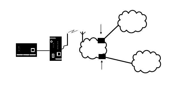
SINAUT MD741-1
125 C79000- G8976-C212
Glossary
AES Advanced Encryption Standard. The NIST (National Institute of
Standards and Technology) has been developing the AES encryption
standard jointly with industrial companies for years. This Æ
symmetrical encryption is designed to replace the previous DES
standard. The AES standard specifies three different key sizes with
128, 192 and 256 bits.
In 1997, the NIST launched the AES initiative and announced its
conditions for the algorithm. Of the encryption algorithms proposed,
the NIST short-listed five; the algorithms MARS, RC6, Rijndael,
Serpent and Twofish. In October 2000, the encryption algorithm
chosen was Rijndael.
APN (Access Point
Name) Trans-network connections, e.g. from a GPRS network to the Internet,
are created in the GPRS network via so-called APNs.
(E-)GPRS
Public
INTERNET
MD741-1
Local
application
Private
INTRANET
APN
(public)
APN
(private)
An end device that wants to establish a connection via the GPRS
network specifies an APN to indicate which network it wants to be
connected to: the Internet or a private company network that is
connected via a dedicated line.
The APN designates the transfer point to the other network. It is
communicated to the user by the network operator.
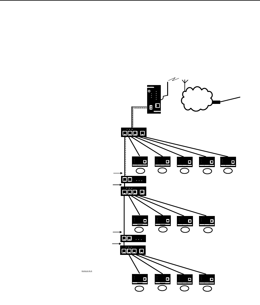
Glossary
SINAUT MD741-1
126 C79000- G8976-C212
Additional Internal
Routes The following sketch shows how the IP addresses could be distributed
in a local network with subnetworks, what network addresses result
from this, and what the specification for an additional internal route
could look like.
APN
(E-)GPRS
MD741-1
Switch
Router
Switch
Switch
Router
A1 A2 A3 A4 A5
B1 B2 B3 B4
C1 C2 C3 C4
Router
IP external: 192.168.11.2
IP internal: 192.168.15.254
Netmask: 255.255.255.0
Router
IP external: 192.168.15.1
IP internal: 192.168.27.254
Netmask: 255.255.255.0
Network A
Network address: 192.168.11.0 / 24
Netmask: 255.255.255.0
Network B
Network address: 192.168.15.0 / 24
Netmask: 255.255.255.0
Network C
Network address: 192.168.27.0 / 24
Netmask: 255.255.255.0
MD741-1 internal address:
192.168.11.1
MD741-1 external address:
(assigned by provider)
e.g. 80.81.192.37
Additional
internal routes
Network A is connected to the SINAUT MD741-1 and via it to a remote
network. Additional internal routes show the path to additional
networks (networks B, C), which are connected to each other via
gateways (routers). For the SINAUT MD741-1, in the example shown
networks B and C can both be reached via gateway 192.168.11.2 and
network address 192.168.11.0/24.
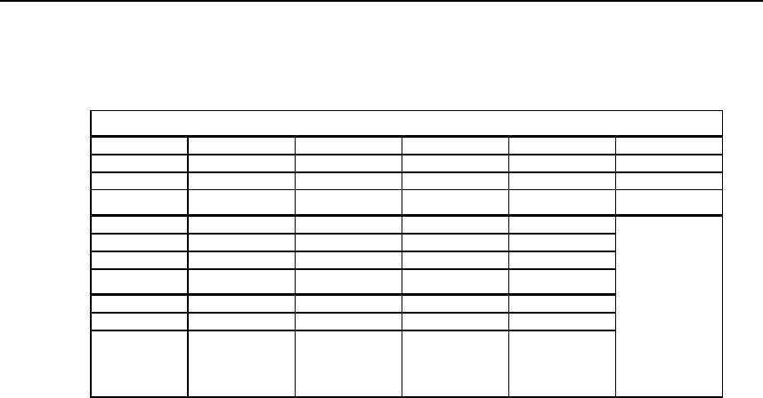
Glossary
SINAUT MD741-1
C79000- G8976-C212 127
Asymmetrical
encryption In asymmetrical encryption, data are encrypted with one key and
decrypted with a second key. Both keys are suitable for encryption and
decryption. One of the keys is kept secret by its owner (Private Key),
the other is issued to the public (Public Key), i.e. possible
communication partners.
A message encrypted with a Public Key can only be decrypted and
read by the recipient who has the corresponding Private Key. A
message encrypted with the Private Key can be decrypted by any
recipient who has the corresponding Public Key. Encryption with the
Private Key shows that the message actually originates from the owner
of the corresponding Public Key. We therefore speak of a digital
signature.
Asymmetrical encryption methods such as RSA are, however, slow
and vulnerable to certain attacks, which is why they are often
combined with a symmetrical method (Æ symmetrical encryption). On
the other hand, concepts are also possible which avoid the complex
administration of symmetrical keys.
CIDR Classless Inter-Domain Routing
IP netmasks and CIDR are notations for grouping a number of IP
addresses into an address space. Thus a range of contiguous
addresses is treated as a network.
The CIDR method reduces, for example the routing tables stored in
routers by means of a postfix in the IP address. This postfix can be
used to designate a network together with its subnetworks. This
method is described in RFC 1518.
In order to specify a range of IP addresses to the SINAUT MD741-1, or
when configuring the firewall, it may be necessary to specify the
address space in the CIDR notation. The following table shows the IP
netmask on the left-hand side, and to the far right the corresponding
CIDR notation.
Network A
Computer A1 A2 A3 A4 A5
IP address 192.168.11.3 192.168.11.4 192.168.11.5 192.168.11.6 192.168.11.7
Network mask 255.255.255.0 255.255.255.0 255.255.255.0 255.255.255.0 255.255.255.0
Network B
Computer B1 B2 B3 B4
IP address 192.168.15.3 192.168.15.4 192.168.15.5 192.168.15.6
Network mask 255.255.255.0 255.255.255.0 255.255.255.0 255.255.255.0
Network C
Computer C1 C2 C3 C4
IP address 192.168.27.3 192.168.27.4 192.168.27.5 192.168.27.6
Network mask 255.255.255.0 255.255.255.0 255.255.255.0 255.255.255.0
Additional
internal
routes:
Network:
192.168.15.0/24
Gateway:
192.168.11.2
Network:
192.168.27.0/24
Gateway:
192.168.11.2

Glossary
SINAUT MD741-1
128 C79000- G8976-C212
IP netmask binary CIDR
255.255.255.255 11111111 11111111 11111111 11111111 32
255.255.255.254 11111111 11111111 11111111 11111110 31
255.255.255.252 11111111 11111111 11111111 11111100 30
255.255.255.248 11111111 11111111 11111111 11111000 29
255.255.255.240 11111111 11111111 11111111 11110000 28
255.255.255.224 11111111 11111111 11111111 11100000 27
255.255.255.192 11111111 11111111 11111111 11000000 26
255.255.255.128 11111111 11111111 11111111 10000000 25
255.255.255.0 11111111 11111111 11111111 00000000 24
255.255.254.0 11111111 11111111 11111110 00000000 23
255.255.252.0 11111111 11111111 11111100 00000000 22
255.255.248.0 11111111 11111111 11111000 00000000 21
255.255.240.0 11111111 11111111 11110000 00000000 20
255.255.224.0 11111111 11111111 11100000 00000000 19
255.255.192.0 11111111 11111111 11000000 00000000 18
255.255.128.0 11111111 11111111 10000000 00000000 17
255.255.0.0 11111111 11111111 00000000 00000000 16
255.254.0.0 11111111 11111110 00000000 00000000 15
255.252.0.0 11111111 11111100 00000000 00000000 14
255.248.0.0 11111111 11111000 00000000 00000000 13
255.240.0.0 11111111 11110000 00000000 00000000 12
255.224.0.0 11111111 11100000 00000000 00000000 11
255.192.0.0 11111111 11000000 00000000 00000000 10
255.128.0.0 11111111 10000000 00000000 00000000 9
255.0.0.0 11111111 00000000 00000000 00000000 8
254.0.0.0 11111110 00000000 00000000 00000000 7
252.0.0.0 11111100 00000000 00000000 00000000 6
248.0.0.0 11111000 00000000 00000000 00000000 5
240.0.0.0 11110000 00000000 00000000 00000000 4
224.0.0.0 11100000 00000000 00000000 00000000 3
192.0.0.0 11000000 00000000 00000000 00000000 2
128.0.0.0 10000000 00000000 00000000 00000000 1
0.0.0.0 00000000 00000000 00000000 00000000 0
Example: 192.168.1.0 / 255.255.255.0 corresponds to CIDR:
192.168.1.0/24
Client / Server In a client/server environment, a server is a program or computer that
receives queries from a client program or client computer and answers
them.
In data communication, a computer that establishes a connection to a
server (or host) is also referred to as a client. That means that the
client is the computer that is calling and the server (or host) is the one
being called.
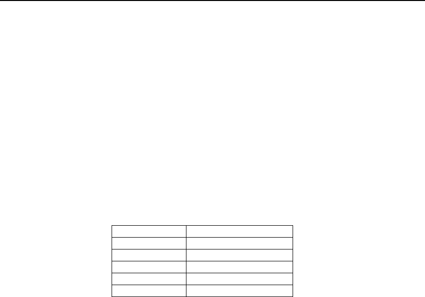
Glossary
SINAUT MD741-1
C79000- G8976-C212 129
CSD 9600 CSD (9600) stands for Circuit Switched Data or dial-in data
connection. Here a connection is created between two users (end
points of the connection), similar to a telephone call over a public
telephone network. User 1 dials the telephone number of user 2. The
network signals to user 2 that there is a call, user 2 accepts the call
and the network establishes the connection until one of the users
terminates the connection again.
In a GSM network this service is called CSD, and allows data
transmission at 9600 bit/s or 14400 bit/s, with transmission being either
secured or unsecured. Possible connections are GSM modem to GSM
modem, analog modem to GSM and ISDN modem to GSM modem.
CSQ / RSSI The CSQ value is a value defined in the GSM standard for indicating
the signal quality. CSQ values correspond to the received field
strength RSSI (= Received Signal Strength Indication):
CSQ RSSI
< 6 < -101 dBm
6 - 10 -101 … - 93 dBm
11 – 18 - 91 dBm … -77 dBm
> 18 > 75 dBm
99 Not logged in
Datagram In the transmission protocol TCP/IP, data are sent in the form of data
packets, the so-called IP datagrams. An IP datagram has the following
structure:
1. IP Header
2. TCP/UDP Header
3. Data (Payload)
The IP Header contains:
• the IP address of the sender (source IP address)
• the IP address of the recipient (destination IP address)
• the protocol number of the protocol of the next higher protocol
layer (according to the OSI layer model)
• the IP Header Checksum for checking the integrity of the header
upon receipt.
TCP/UDP Header contains the following information:
• the port of the sender (source port)
• the port of the recipient (destination port)
• a checksum for the TCP Header and a few items of information
from the IP Header (source and destination IP addresses, etc.)

Glossary
SINAUT MD741-1
130 C79000- G8976-C212
DES/3DES The symmetrical encryption algorithm (Æ symmetrical encryption)
DES, originally developed by IBM and checked by the NSA, was
determined in 1977 by the American National Bureau of Standards, the
predecessor of today's National Institute of Standards and Technology
(NIST), as the standard for American government institutions.
As this was the first standardized encryption algorithm of all, it quickly
established itself in industry and hence outside the USA.
DES works with a key length of 56 bits, which is no longer considered
secure due to the increase in computing power since 1977.
3DES is a variant of DES. It works with 3-times larger keys, i.e. 168
bits long. It is still considered secure today and is, among other things,
also part of the IPsec standard.
DHCP The Dynamic Host Configuration Protocol (DHCP) performs automatic
dynamic assignment of IP addresses and other parameters in a
network. The Dynamic Host Configuration Protocol uses UDP. It was
defined in RFC 2131 and was assigned the UDP ports 67 and 68.
DHCP uses the client – server method, in which the client is assigned
the IP addresses by the server.
DNS Addressing in IP networks is always by means of IP addresses. It is
generally preferable, however, to specify the addressing in the form of
a domain address (i.e. in the form www.abc.xyz.de). If the addressing
is by means of the domain address, then the sender first sends the
domain address to a domain name server (DNS) and gets back the
associated IP address. Only then does the sender address its data to
this IP address.
DynDNS provider Also Dynamic DNS provider. Every computer that is connected to the
Internet has an IP address (IP = Internet Protocol). An IP address
consists of up to 4 three-digit numbers, with dots separating each of
the numbers. If the computer is online via the telephone line via
modem, ISDN or ADSL, then the Internet service provider dynamically
assigns it an IP address, i.e. the address changes from session to
session. Even if the computer is online for more than 24 hours without
interruption (e.g. in the case of a flat rate), the IP address is changed
periodically.
For a local computer to be accessible via the Internet, its address must
be known to the external remote station. This is necessary for it to
establish a connection to the local computer. This is not possible,
however, if the address of the local computer constantly changes. It is
possible, however, if the user of the local computer has an account
with a DynamicDNS provider (DNS = Domain Name Server).
Then he can specify there a hostname under which the computer can
be accessed in the future, e.g.: www.xyz.abc.de. Moreover, the
DynamicDNS provider makes available a small program that has to be
installed and executed on the computer concerned. In each Internet
session of the local computer this tool reports to the DynamicDNS
provider which IP address the computer has at the moment. Its domain
name server registers the current hostname - IP address assignment
and reports this to other domain name servers in the Internet.
If now an external computer wants to establish a connection with a

Glossary
SINAUT MD741-1
C79000- G8976-C212 131
local computer which is registered with the DynamicDNS provider, the
external computer uses the hostname of the local computer as the
address. In this way a connection is established with the responsible
DNS (Domain Name Server) in order to look up there the IP address
which is currently assigned to this hostname. The IP address is
transmitted back to the external computer, and then used by it as the
destination address. This now leads precisely to the desired local
computer.
As a rule, all Internet addresses are based on this method: First a
connection is established to a DNS in order to determine the IP
addresses assigned to this hostname. Once that has been done, the
IP address that was "looked up" is used to establish the connection to
the desired remote station, which can be any Web site.
EDGE EDGE (= Enhanced Data Rates for GSM Evolution) refers to a method
in which the available data rates in GSM mobile phone networks are
increased by introducing an additional modulation process. With
EDGE, GPRS is expanded to become EGPRS (Enhanced GPRS), and
HSCSD is expanded to become ECSD.
EGPRS EGPRS stands for "Enhanced General Packet Radio Service", which
describes a packet-oriented data service based on GPRS, which is
accelerated by means of EDGE technology.
GPRS GPRS is the abbreviation for "General Packet Radio Service", a data
transmission system of GSM2+ mobile phone systems. GPRS systems
use the basestations of GSM networks as their wireless equipment,
and their own infrastructure for coupling to other IP networks, such as
the Internet. Data communication is packet-oriented; the Internet
Protocol (IP) is used. GPRS provides data rates of up to 115.2 KBit/s.
GSM GSM (= Global System for Mobile Communication) is a standard that is
used worldwide for digital mobile phone networks. In addition to the
voice service for telephone calls, GSM supports various data services,
such as fax, SMS, CSD and GPRS. Depending on the legal
requirements in the various countries, the frequency bands 900 MHz,
1800 MHz or 850 MHz and 1900 MHz are used.
HTTPS HTTPS (=HyperText Transfer Protocol Secure) is a variant of the
familiar HTTP, which is used by any Web browser for navigation and
data exchange in the Internet.
In HTTPS the original protocol is supplemented with an additional
component for data protection. While in HTTP data are transmitted
unprotected in plain text, in HTTPS data are transmitted only after an
exchange of digital certificates, and in encrypted form.
IP address Every host or router on the Internet / an intranet has a unique IP
address (IP = Internet Protocol). The IP address is 32 bits (= 4 bytes)
long, and is written as 4 numbers (each in the range from 0 to 255),
which are separated from each other by dots.
An IP address has 2 parts: the network address and the host address.
All hosts of a network have the same network address, but different
host addresses. Depending on the size of the network in question - a
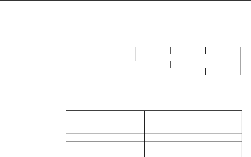
Glossary
SINAUT MD741-1
132 C79000- G8976-C212
distinction is made between networks of Class A, B and C - the two
address components may be of different sizes:
1st byte 2nd byte 3rd byte 4th byte
Class A Netw. addr. Host addr.
Class B Netw. addr. Host addr.
Class C Netw. addr. Host addr.
It can be seen from the first byte of the IP address whether the IP
address designates a network of Class A, B or C. The following
definitions apply:
Value of the
1st byte
Bytes for the
network
address
Bytes for the host
address
Class A 1-126 1 3
Class B 128-191 2 2
Class C 192-223 3 1
If you do the arithmetic, you can see that there can be a maximum of
126 Class A networks worldwide, and each of these networks can
comprise a maximum of 256 x 256 x 256 hosts (3 bytes of address
space). There can be 64 x 256 Class B networks, each of which can
contain up to 65,536 hosts (2 bytes of address space: 256 x 256).
There can be 32 x 256 x 256 Class C networks, each of which can
contain up to 256 hosts (1 byte of address space).
IP packet See Datagram
IPsec IP security (IPsec) is a standard that makes it possible to ensure the
authenticity of the sender, the confidentiality and the integrity of the
data in IP datagrams by means of encryption. The components of
IPSec are the Authentication Header (AH), the Encapsulating Security
Payload (ESP), the Security Association (SA), the Security Parameter
Index (SPI) and the Internet Key Exchange (IKE).
When communication starts the computers involved clarify the method
used and its implications, e.g. Transport Mode or Tunnel Mode.
In Transport Mode an IPSec header is inserted into each IP datagram
between the IP header and the TCP or UDP header. As the IP header
is not changed this mode is suitable only for a host-to-host connection.
In Tunnel Mode an IPSec header and a new IP header are inserted in
front of the entire IP datagram. This means that the original datagram
is contained, encrypted as a whole, in the payload of the new
datagram.
The Tunnel Mode is used in the VPN: the devices at the tunnel ends
perform the encryption and decryption of the datagrams, while the
datagrams themselves remain completely protected as they pass
through the tunnel, i.e. during transmission via a public network.

Glossary
SINAUT MD741-1
C79000- G8976-C212 133
NAT (Network Address
Translation) In Network Address Translation (NAT) - often also referred to as IP
Masquerading - an entire network is "hidden" behind a single device,
the NAT router. This device is usually a router. The internal computers
in the local network remain hidden with their IP addresses when they
communicate to the outside via the NAT router. For the external
communication partners only the NAT router with its own IP address
appears.
However, in order for internal computers to be able to communicate
direct with external computers (on the Internet) the NAT router must
change the IP datagrams passing from internal computers to the
outside and from the outside to an internal computer.
If an IP datagram is sent from the internal network to the outside the
NAT router changes the datagram's IP and TCP headers. It replaces
the source IP address and the source port with its own official IP
address and its own, previously unused port. To this end it creates a
table showing the correlation between the original values and the new
ones.
When receiving a reply datagram the NAT router recognises by means
of the destination port specified that the datagram is actually intended
for an internal computer. Using the table the NAT box exchanges the
destination IP address and the destination port and forwards the
datagram to the internal network.
Network mask / Subnet
mask A company network with access to the Internet is normally officially
assigned only a single IP address, e.g. 134.76.0.0. In this example
address it can be seen from the 1st byte that this company network is
a Class B network, i.e. the last 2 bytes can be used freely for host
addressing. Arithmetically that represents an address space of 65,536
possible hosts (256 x 256).
Such a huge network is not very practical. It is necessary here to form
subnetworks. This is done using a subnet mask. Like an IP address,
this is a field 4 bytes long. The value 255 is assigned to each of the
bytes that represent the network address. The main purpose of this is
to "hide" a part of the host address range in order to use it for the
addressing of subnetworks. For example, in a Class B network (2
bytes for the network address, 2 bytes for the host address), by means
of the subnet mask 255.255.255.0 it is possible to take the 3rd byte,
which was actually intended for host addressing, and use it now for
subnet addressing. Arithmetically that means that 256 subnets with
256 hosts each could be created.
Port number The Port Number field is a 2-byte field in UDP and TCP headers. The
assignment of port numbers serves to identify various data flows that
are processed simultaneously by UDP/TCP. The entire data exchange
between UDP/TCP and the application processes takes place via
these port numbers. The assignment of port numbers to application
processes is performed dynamically and randomly. Fixed port numbers
are assigned for certain frequently-used application processes. These
are called Assigned Numbers.

Glossary
SINAUT MD741-1
134 C79000- G8976-C212
PPPoE Acronym for Point-to-Point Protocol over Ethernet. It is based on the
standards PPP and Ethernet. PPPoE is a specification for connecting
users to the Internet via Ethernet using a jointly used broadband
medium such as DSL, Wireless LAN or cable modem.
PPTP Acronym for Point-to-Point Tunneling Protocol. This protocol was
developed by Microsoft, U.S. Robotics and others in order to transmit
data securely between two VPN nodes (Æ VPN) over a public network.
Private Key, Public
key; Certification
(X.509)
In asymmetrical encryption algorithms 2 keys are used: a Private Key
and a Public Key. The public key serves to encrypt data and the
private key to decrypt them.
The public key is provided by the future recipient of the data to those
who will send the data to him in encrypted form. The private key is
possessed only by the recipient and serves to decrypt the received
data.
Certification:
So that the user of the public key (for encryption) can be certain that
the public key conveyed to him really does come from the entity that is
to receive the data to be sent, certification can be used: the verification
of the authenticity of the public key and the consequent link between
the identity of the sender and his key is performed by a Certification
Authority or CA. This is done according to the rules of the CA, for
example by the sender being required to appear in person. Following
successful inspection the CA signed the sender's public key with its
(digital) signature. A certificate is created.
An X.509 certificate makes a connection between an identity in the
form of an 'X.500 Distinguished Name' (DN) and a public key. This
connection is authenticated by the digital signature of an X.509
Certification Authority (CA). The signature - an encryption with the
signature key - can be checked with the private key issued by the CA
to the certificate holder.
Protocol, Transfer
protocol Devices that communicate with each other must use the same rules.
They have to "speak the same language". Such rules and standards
are called protocols or transfer protocols. Frequently used protocols
include IP, TCP, PPP, HTTP and SMTP. TCP/IP is the umbrella term
for all protocols that are based on IP.
Service provider Supplier, company or institution that gives users access to the Internet
or to an online service.
Spoofing, Anti-
Spoofing In Internet terminology, spoofing means to specify a forged address.
The forged Internet address is used to pose as an authorised user.
Anti-spoofing means mechanisms to reveal or prevent spoofing.
SSH SSH (Secure Shell) is a protocol that enables secure, encrypted data
exchange between computers. Secure SHell is used for remote access
to the input console from LINUX-based machines.

Glossary
SINAUT MD741-1
C79000- G8976-C212 135
Stateful inspection
firewall A stateful inspection firewall is a packet filtering method. Packet filters
only let IP packets through if this has been defined previously using
firewall rules. The following is defined in the firewall rules:
• which protocol (TCP, UDP, ICMP) can go through,
• the permitted source of the IP packets (From IP / From port)
• the permitted destination of the IP packets (To IP / To port)
It is likewise defined here what will be done with IP packets that are
not allowed through (discard, reject).
For a simple packet filter it is always necessary to create two firewall
rules for a connection:
• One rule for the query direction from the source to the destination,
and
• a second rule for the query direction from the destination to the
source.
It is different with a stateful inspection firewall. Here a firewall rule is
only created for the query direction from the source to the destination.
The firewall rule for the response direction from the destination to the
source results from analysis of the data previously sent. The firewall
rule for the responses is closed again after the responses are received
or after a short time period has elapsed. Thus responses can only go
through if there was a previous query. This means that the response
rule cannot be used for unauthorised access. What is more, special
procedures make it possible for UDP and ICMP data to also go
through, even though these data were not requested before.
Symmetrical
encryption With symmetrical encryption the data are encrypted and decrypted
using the same key. Examples of symmetrical encryption algorithms
are DES and AES. These are fast, but require complex administration
as the number of users increases.

Glossary
SINAUT MD741-1
136 C79000- G8976-C212
TCP/IP (Transmission
Control
Protocol/Internet
Protocol
Network protocol that is used to connect two computers on the
Internet.
IP is the basic protocol.
UDP builds on IP, and sends individual packets. These can arrive at
the recipient in a different sequence from the one they were sent in, or
they can even get lost.
TCP serves to secure the connection, and ensures, for example, that
the data packets are forwarded to the application in the right
sequence.
UDP and TCP provide, in addition to the IP addresses, port numbers
between 1 and 65535, which can be used to distinguish the various
services.
A number of additional protocols are based on UDP and TCP, such as
HTTP (Hyper Text Transfer Protocol), HTTPS (Secure Hyper Text
Transfer Protocol), SMTP (Simple Mail Transfer Protocol), POP3 (Post
Office Protocol, Version 3), DNS (Domain Name Service).
ICMP builds on IP, and contains control messages.
SMTP is an e-mail protocol based on TCP.
IKE is an IPsec protocol based on UDP.
ESP is IPsec protocol based on IP.
On a Windows PC, WINSOCK.DLL (or WSOCK32.DLL) handles both
of these protocols.
(Æ Datagram)
UDP See TCP/IP
VPN (Virtual Private
Network) A Virtual Private Network (VPN) connects several separate private
networks (subnets) via a public network, e.g. the Internet, to form a
shared network. Confidentiality and authenticity are ensured by using
cryptographic protocols. A VPN therefore provides an inexpensive
alternative to dedicated lines when it comes to setting up a
supraregional corporate network.

Glossary
SINAUT MD741-1
C79000- G8976-C212 137
X.509 A kind of "seal" which proves the authenticity of a Public Key (Æ
asymmetrical encryption) and appendant data.
So that the user of the public key for encryption can be certain that the
public key conveyed to him really does come from its issuer and hence
from the entity that is to receive the data to be sent, certification can be
used. This verification of the authenticity of the public key and the
consequent link between the identity of the issuer and his key is
performed by a Certification Authority or CA. This is done according to
the rules of the CA, for example by the issuer of the public key being
required to appear in person. Following successful inspection the CA
signs the public key with its (digital) signature. A certificate is created.
An X.509(v3) certificate therefore contains a public key, information
about the key owner (given as Distinguished Name (DN)), permitted
designated uses, etc. and the signature of the CA.
The signature is created as follows: from the bit sequence of the public
key, the data on its owner and other data, the CA creates an individual
bit sequence which can be up to 160 bits long, the HASH value. This is
encrypted by the CA using its private key and added to the certificate.
Encryption with the CA's private key is proof of authenticity, i.e. the
encrypted HASH character sequence is the digital signature of the CA.
Should the data of the certificate be changed without authorization, the
HASH value is no longer correct and the certificate then becomes
worthless.
The HASH value is also known as the fingerprint. As it is encrypted
with the private key of the CA, anyone in possession of the
corresponding public key can decrypt the bit sequence and thus check
the authenticity of the fingerprint or signature in question.
Involving certification authorities means that not every key owner
needs to know the other one, but only the certification authority used.
The additional key information also simplifies the administrability of the
key.
X.509 certificates are employed, e.g. in e-mail encryption, using
S/MIME or IPsec.