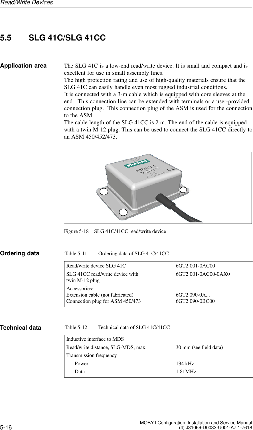
Siemens MOBYI-SLG41N SLG 41 Inductive TAG System User Manual MOBY I en A71

Siemens AG SLG 41 Inductive TAG System MOBY I en A71

Users Manual

Table of ContentsGeneral 1Introduction to MOBY I 2Configuration and MountingGuidelines 3Mobile Data Memories 4Read/Write Devices 5Interfaces 6Accessories 7Documentation AError Messages BASCII Table CCompatibility DPublished in January, 20026GT2 097-4BA00-0EA2 Configuration, Installation andServiceManualMOBYR I
iiThis manual contains notices which you should observe to ensure your own personal safety, aswell as to protect the product and connected equipment. These notices are highlighted in themanual by a warning triangle and are marked as follows according to the level of danger.!Dangerindicates that death, severe personal injury or substantial property damage will result if properprecautions are not taken.!Warningindicates that death, severe personal injury or substantial property damage can result if properprecautions are not taken.!Cautionindicates that minor personal injury or property damage can result if proper precautions are not taken.Notedraws your attention to particularly important information on the product, handling the product, orto a particular part of the documentation.Only qualified personnel should be allowed to install and work on this equipment. For the pur-poses of the safety notes contained in this manual; qualified persons are defined as persons whoare authorized to commission, to ground, and to tag circuits, equipment, and systems in accor-dance with established safety practices and standards.Note the following.!WarningThis device and its components may only be used for the applications described in the catalog or thetechnical description, and only in connection with devices or components from other manufacturerswhich have been approved or recommended by Siemens.This product can only function correctly and safely if it is transported, stored, set up, and installedcorrectly, and operated and maintained as recommended.MOBYR, SIMATICR and SINECR are registered trademarks of SIEMENS AG.Some of the other designations used in this documentation are also registered trademarks; theowner’s rights may be violated if they are used by third parties for their own purposes.We have checked the contents of this manual for agreement with thehardware and software described. Since deviations cannot be pre-cluded entirely, we cannot guarantee full agreement. However, thedata in this manual are reviewed regularly and any necessary cor-rections included in subsequent editions. Suggestions for improve-ment are welcomed.E Siemens AG 1997, 1998, 1999, 2000, 2001, 2002Technical data subject to changeDisclaimer of LiabilityCopyright E Siemens AG 1997 All rights reservedThe reproduction, transmission or use of this document or itscontents is not permitted without express written authority.Offenders will be liable for damages. All rights, including rightscreated by patent grant or registration of a utility model or design, arereserved.Siemens AGAutomation and DrivesSystems EngineeringPostfach 23 55, D-90713 FuerthSiemens Aktiengesellschaft Order No. 6GT2 097-4BA00-0EA2Safety GuidelinesQualified PersonnelCorrect UsageTrademarks
3-1MOBY I Configuration, Installation and Service Manual(4) J31069-D0033-U001-A7.1-7618Configuration and Mounting Guidelines 3
3-2 MOBY I Configuration, Installation and Service Manual(4) J31069-D0033-U001-A7.1-76183.1 Basic Requirements!WarningDo not make changes to the devices.Violation will invalidate interference emission certification (BZT, FCC), CEand the manufacturer’s warranty.NoteAny unauthorized modifications to this device could void the user’s author-ity to operate the equipment.To choose the correct MOBY I components, apply the following criteria toyour particular application.STransmission distance (i.e., read/write distance)SThe amount of data to be transferredSMetal-free spaces for MDS and SLGSStatic or dynamic transmission of the dataSSpeed for dynamic transmissionSTolerances of the trackingSEnvironmental conditions (e.g., moisture, temperature, chemical in-fluences and so on)FCC ComplianceStatementConfiguration and Mounting Guidelines
5-12 MOBY I Configuration, Installation and Service Manual(4) J31069-D0033-U001-A7.1-76185.4 SLG 41/SLG 41-SThe SLG 41 is a low-end read/write device.  It is particularly suitable for usewhen the MDS conveyor system (e.g., pallets) can be physically positionedrelatively precisely.  The swivel head of the SLG 41 makes it very adaptableto the transportation system.In dynamic operation, only a small amount of data can be read or writtenbetween SLG 41 and MDS.In contrast to the SLG 41, the antenna of the SLG 41-S is rotated by 90° inthe swivel head so that all positions of the transmission window can be im-plemented.Figure 5-12 SLG 41Table 5-8 Ordering data for SLG 41/SLG 41-SRead/write device up to 25 mmSLG 41SLG 41-S (antenna turned 90°)SLG plug connector and stub lines6GT2 001-0AA006GT2 001-0AA00-ZA23See chapter 3.10Table 5-9 Technical data of SLG 41/SLG 41-SInductive interface to MDSData transmission speed 19200 baudRead/write distanceSLG to MDS (max.) 30 mm (see field data table)Transmission frequencySPower 134 kHzSData 1.81 MHzSerial interface to ASM 6-pin SLG plug connector in acc. w. DIN 43651Transmission speed 19200 baud, RS 422Line length, ASM to SLG (max.) at 24 V DC 360 mSupply voltage (via serial interface)Nominal value 24 V DCPermissible range 20 to 30 V DCApplication areaOrdering dataTechnical dataRead/Write Devices
5-13MOBY I Configuration, Installation and Service Manual(4) J31069-D0033-U001-A7.1-7618Table 5-9 Technical data of SLG 41/SLG 41-SCurrent consumptionIdle/operation 20 mA / 90 mAMTBF 2 x 10⁶HousingDimensions in mm (W x H x D) 120 x 40 x 40Color Anthracite/ergo-grayMaterial Polyamide 12Plug connection DIN 43651Protection rating IP65Shock 50 gVibration 20 gMounting of SLG 4 M5 screwsTurning moment (at room temperature) v 3 NmAmbient temperatureDuring operation –25° to +70° CDuring transportation and storage –40° to +85° CWeight (approx.) 210 gThe exact field data are dependent on the type of MDS used.Table 5-10 Field data of SLG 41/SLG 41-SOperating distance (Sa)0 to 15 mmLimit distance (Sg)30 mmMedian deviation (L) Depends on MDSMinimum distance from SLG to SLG (D) > 200 mmMade in GermanySIEMENS MOBY I SLG 41THIS DEVICE COMPLIES WITH PART 15 OF THE  FCC RULES: OPERATION IS SUBJECT TOTHE FOLLOWING TWO CONDITIONS:(1) THIS DEVICE MAY NOT CAUSE HARMFUL INTERFERENCE, AND (2) THIS DEVICE MUSTACCEPT ANY INTERFERENCE THAT MAY CAUSE UNDESIRED OPERATION.NoteThe manufacturer is not responsible for any radio or TV interference causedby unauthorized modifications to this equipment:Such modifications could void the user’s authority to operate the equipment.Field dataFCC informationRead/Write Devices
5-14 MOBY I Configuration, Installation and Service Manual(4) J31069-D0033-U001-A7.1-7618SIEMENSM MSIEMENSMMTransmission window at operating distanceLength oftransmissionwindow (L)SLG 41-STransmission win-dow at operatingdistanceLength of trans-mission window(L)Figure 5-13 Transmission window of SLG 41/SLG 41-SaaaaaaSIEMENSSIEMENSaaaaaaSIEMENSSIEMENSa = 25 mmMetal-free spacewith flush installationa = 25 mmMetal-freespace with flushinstallationFigure 5-14 Metal-free space for SLG 41/SLG 41-SDDSLG 41 / SLG 41-SSLG 41SLG 41Figure 5-15 Distance D for SLG 41/SLG 41-STransmissionwindowMetal-free spaceDefinition ofdistance DRead/Write Devices
5-15MOBY I Configuration, Installation and Service Manual(4) J31069-D0033-U001-A7.1-76184080405,3 602528404940 3014.5SIEMENS4080405.3 602528404940 3014.5SIEMENSSLG 41:SLG 41-S:Position ofswivel headon deliveryPosition ofswivel headon delivery.3Figure 5-16 Dimensional diagram of SLG 41/SLG 41-SSIEMENSSIEMENSSIEMENSSIEMENSSLG 41SLG 41-SFigure 5-17 Read head changes of SLG 41/SLG 41-SDimensions(in mm)Possible read headchanges with theswivel headRead/Write Devices
5-16 MOBY I Configuration, Installation and Service Manual(4) J31069-D0033-U001-A7.1-76185.5 SLG 41C/SLG 41CCThe SLG 41C is a low-end read/write device. It is small and compact and isexcellent for use in small assembly lines.The high protection rating and use of high-quality materials ensure that theSLG 41C can easily handle even most rugged industrial conditions.It is connected with a 3-m cable which is equipped with core sleeves at theend.  This connection line can be extended with terminals or a user-providedconnection plug.  This connection plug of the ASM is used for the connectionto the ASM.The cable length of the SLG 41CC is 2 m. The end of the cable is equippedwith a twin M-12 plug. This can be used to connect the SLG 41CC directly toan ASM 450/452/473.Figure 5-18 SLG 41C/41CC read/write deviceTable 5-11 Ordering data of SLG 41C/41CCRead/write device SLG 41CSLG 41CC read/write device withtwin M-12 plugAccessories:Extension cable (not fabricated)Connection plug for ASM 450/4736GT2 001-0AC006GT2 001-0AC00-0AX06GT2 090-0A...6GT2 090-0BC00Table 5-12 Technical data of SLG 41C/41CCInductive interface to MDSRead/write distance, SLG-MDS, max.Transmission frequencyPowerData30 mm (see field data)134 kHz1.81MHzApplication areaOrdering dataTechnical dataRead/Write Devices
5-17MOBY I Configuration, Installation and Service Manual(4) J31069-D0033-U001-A7.1-7618Table 5-12 Technical data of SLG 41C/41CCSerial interface to evaluation unitData transmission rateLine length, ASM-SLG max. (for 24V DC)RS 42219 200 Baud360 mSerial interface to userSLG 41CSLG 41CC3 m connection line;open end2 m connection line;twin M-12 plug forASM 450/452/473VoltageNominal valuePermissible rangeCurrent consumption at room temeratureStandbyOperation24 V DC20 V to 30 V DC30 mA70 mA (typical)HousingDimensions (L x W x H) in mmColorMaterialConnection55 x 75 x 30GrayPlastic (polyamide 12)3 m connection line, cable endswith core sleeves and labelsProtection rating an acc. w. EN 60 529ShockVibrationIP6750 g20 gMounting of SLGTightening moment (at room temperature)4 M 5 screws< 2 NmAmbient temperatureDuring operationDuring transpostation and storage–25°C to +70°C–40°C to +85°CWeight approx. 210 gRead/Write Devices
5-18 MOBY I Configuration, Installation and Service Manual(4) J31069-D0033-U001-A7.1-7618Table 5-13 Field data of SLG 41C/41CCMDS 401/402 MDS 403 MDS 404/514Working distance (Sa)0 to 6 4 to 15 0 to 12Limit distance (Sg) 10 30 25Transmission windowSL: VerticalS2L: Horizontal204065–3060Width of transmission window (W) 8 25 12Minimum distance from SLG to SLG w200 w200 w200Made in GermanySIEMENS MOBY I SLG 41CTHIS DEVICE COMPLIES WITH PART 15 OF THE  FCC RULES: OPERATION IS SUBJECT TOTHE FOLLOWING TWO CONDITIONS:(1) THIS DEVICE MAY NOT CAUSE HARMFUL INTERFERENCE, AND (2) THIS DEVICE MUSTACCEPT ANY INTERFERENCE THAT MAY CAUSE UNDESIRED OPERATION.NoteThe manufacturer is not responsible for any radio or TV interference causedby unauthorized modifications to this equipment:Such modifications could void the user’s authority to operate the equipment.Field data (in mm)FCC informationRead/Write Devices
5-19MOBY I Configuration, Installation and Service Manual(4) J31069-D0033-U001-A7.1-7618The transmission windowis marked on the housingLength of the transmission window for (L)MDS 404/514Length of the transmission window (L)for MDS 401/402121255MMMTransmission windowat working distance2030B = 25Width of thetransmission windowL = 65Length of thetransmission window Transmission windowat working distanceThe MDS moves along the“SIEMENS” label on thehousing.MSIEMENSMLenght of the transmisison window forMDS 403MFigure 5-19 Transmission window of SLG 41C/41CCTransmission windowRead/Write Devices
5-20 MOBY I Configuration, Installation and Service Manual(4) J31069-D0033-U001-A7.1-7618a = 15 mm Metal-free area with flush installationSIEMENSMOBY ISLG 41Caaa aFigure 5-20 Metal-free area of SLG 41C/41CCMinimum distance from SLG to SLGD = ≥ 200 mmSIEMENSMOBY ISLG 41CDDSIEMENSMOBY ISLG 41CSIEMENSMOBY ISLG 41CFigure 5-21 Distance D: SLG 41C/41CCMetal-free spaceDefinition of distance DRead/Write Devices
5-21MOBY I Configuration, Installation and Service Manual(4) J31069-D0033-U001-A7.1-7618∅5.545 557565w30Core and sleevesFlexible cable anti-kink guard3 m0.1 m5530SIEMENSMOBY ISLG 41C∅5.545 557565w302 mSIEMENSMOBY ISLG 41CCCore color DesignationBrown – ReceivingPink + 24 VGray Ground (0V)Green + SendingYellow – SendingWhite + ReceivingBlack Cable shieldFigure 5-22 Dimensions of SLG 41C/41CCDimensions (in mm)Read/Write Devices

Navigation menu