Siemens MOBYU-MDSU524 Active transponder for identification system User Manual J31069 D0139 U001 A2 7618
Siemens AG Active transponder for identification system J31069 D0139 U001 A2 7618
Siemens >
Contents
user manual
Table of Contents
General 1
Introduction, MOBY U 2
Configuration and Installation
Guidelines 3
Mobile Data Memories 4
Read/Write Devices 5
Interfaces 6
Accessories 7
Documentation A
Error Messages B
ASCII Table C
Published in December, 2001
6GT2 597-4BA00-0EA2
Configuration, Installation and
Service
Manual
Preliminary Version
MOBYU
Notes on safety
This manual contains notes which must be adhered to for your own personal safety and to prevent property
damage. The notes are highlighted with a warning triangle and graduated by amount of danger.
!Danger
Means that death, severe injury or substantial property damage will occur if these precautions are
not taken.
!Warning
Means that death, severe injury or substantial property damage may occur if these precautions are
not taken.
!Caution
Means that injury or property damage may occur if these precautions are not taken.
Note
Is an important piece of information on the product, its handling or a particular part of the
documentation which requires special attention.
Qualified personnel
A device may only be commissioned and operated by qualified personnel. For the purpose of the safety notes in
this manual, qualified personnel are those persons who are authorized to commission, ground and tag devices,
systems and current circuits in accordance with applicable safety standards.
Intended use
Comply with the following.
!Warning
The product may only be used for the applications described in the catalog and the technical
description and only in connection with Siemens equipment or devices and components of other
manufacturers recommended by Siemens.
Correct and safe operation of the product is based on correct transportation, correct storage, setup
and installation as well as careful operator control and maintenance.
Brand names
SIMATICR and MOBYR and SINEC R are registered brand names of SIEMENS AG.
The other designations in this publication may be brand names whose use by third parties for their own purposes
may violate the rights of the owner.
Although we have checked this publication for agreement with the actual
hardware and software, we cannot fully exclude differences and do not
accept liability for full agreement. The information in this publication is
checked at regular intervals and necessary changes included in the next
release. Your suggestions and ideas are welcome (use the form at the end
of this manual).
Disclaimer of liabilityCopyright Siemens AG 2001 All rights reserved
Reproduction, utilization and revelation of the contents of this manual is
prohibited unless express permission is obtained. Violations will be
prosecuted. All rights reserved particularly when a patent is granted or a utility
model is registered.
Siemens AG
Bereich Automatisierungs- und Antriebstechnik (A&D)
Geschäftsgebiet Systems Engineering
Postfach 2355, D-90713 Fuerth E Siemens AG 2001
Subject to technical change without prior notice
Siemens Aktiengesellschaft Order no. 6GT2597-4BA00-0EA2
i
MOBY U – Manual for Configuration, Installation and Service
(4) J31069-D0139-U001-A2-7618
Table of Contents
1 General 1-1. . . . . . . . . . . . . . . . . . . . . . . . . . . . . . . . . . . . . . . . . . . . . . . . . . . . . . . . . . . . . . . .
2 Introduction – MOBY U 2–1. . . . . . . . . . . . . . . . . . . . . . . . . . . . . . . . . . . . . . . . . . . . . . . . .
3 Configuration and Installation Guidelines 3–1. . . . . . . . . . . . . . . . . . . . . . . . . . . . . . . .
3.1 The Fundamentals 3–2. . . . . . . . . . . . . . . . . . . . . . . . . . . . . . . . . . . . . . . . . . . . . .
3.1.1 Transmission Window 3–3. . . . . . . . . . . . . . . . . . . . . . . . . . . . . . . . . . . . . . . . . . . .
3.2 Basic Requirements 3–5. . . . . . . . . . . . . . . . . . . . . . . . . . . . . . . . . . . . . . . . . . . . .
3.3 EMC Guidelines 3–6. . . . . . . . . . . . . . . . . . . . . . . . . . . . . . . . . . . . . . . . . . . . . . . . .
3.3.1 Preface 3–6. . . . . . . . . . . . . . . . . . . . . . . . . . . . . . . . . . . . . . . . . . . . . . . . . . . . . . . .
3.3.2 General 3–7. . . . . . . . . . . . . . . . . . . . . . . . . . . . . . . . . . . . . . . . . . . . . . . . . . . . . . . .
3.3.3 Spreading of Interference 3–8. . . . . . . . . . . . . . . . . . . . . . . . . . . . . . . . . . . . . . . . .
3.3.4 Cabinet Layout 3–11. . . . . . . . . . . . . . . . . . . . . . . . . . . . . . . . . . . . . . . . . . . . . . . . . .
3.3.5 Avoiding Sources of Interference 3–14. . . . . . . . . . . . . . . . . . . . . . . . . . . . . . . . . .
3.3.6 Equipotential Bonding 3–15. . . . . . . . . . . . . . . . . . . . . . . . . . . . . . . . . . . . . . . . . . . .
3.3.7 Shielding the Cables 3–16. . . . . . . . . . . . . . . . . . . . . . . . . . . . . . . . . . . . . . . . . . . . .
3.3.8 Basic EMC Rules 3–18. . . . . . . . . . . . . . . . . . . . . . . . . . . . . . . . . . . . . . . . . . . . . . .
3.4 MOBY Shielding Concept 3–20. . . . . . . . . . . . . . . . . . . . . . . . . . . . . . . . . . . . . . . .
3.4.1 SLG Cable between ASM 475 and SLG U92 with RS 422 3–20. . . . . . . . . . . . .
3.5 SLG Cable and Plug Connector Allocations (RS 422) 3–21. . . . . . . . . . . . . . . .
3.5.1 Cable Configuration 3–21. . . . . . . . . . . . . . . . . . . . . . . . . . . . . . . . . . . . . . . . . . . . .
3.5.2 Plug Connector Allocations 3–22. . . . . . . . . . . . . . . . . . . . . . . . . . . . . . . . . . . . . . .
3.5.3 Connection Cables 3–24. . . . . . . . . . . . . . . . . . . . . . . . . . . . . . . . . . . . . . . . . . . . . .
3.6 SLG Cable and Plug Allocations (RS 232) 3–26. . . . . . . . . . . . . . . . . . . . . . . . . .
3.6.1 Cable Configuration 3–26. . . . . . . . . . . . . . . . . . . . . . . . . . . . . . . . . . . . . . . . . . . . .
3.6.2 Connection Cables with Lengths 3–27. . . . . . . . . . . . . . . . . . . . . . . . . . . . . . . . . . .
3.7 Service Cable and Plug Allocations 3–29. . . . . . . . . . . . . . . . . . . . . . . . . . . . . . . .
3.7.1 Cable Configuration 3–29. . . . . . . . . . . . . . . . . . . . . . . . . . . . . . . . . . . . . . . . . . . . .
3.7.2 Plug Allocations 3–29. . . . . . . . . . . . . . . . . . . . . . . . . . . . . . . . . . . . . . . . . . . . . . . . .
3.7.3 Connection Cables with Lengths 3–29. . . . . . . . . . . . . . . . . . . . . . . . . . . . . . . . . . .
4 Mobile Data Memories 4–1. . . . . . . . . . . . . . . . . . . . . . . . . . . . . . . . . . . . . . . . . . . . . . . . . .
4.1 Introduction 4–2. . . . . . . . . . . . . . . . . . . . . . . . . . . . . . . . . . . . . . . . . . . . . . . . . . . . .
4.2 MDS U313 4–6. . . . . . . . . . . . . . . . . . . . . . . . . . . . . . . . . . . . . . . . . . . . . . . . . . . . .
4.3 MDS U524 4–9. . . . . . . . . . . . . . . . . . . . . . . . . . . . . . . . . . . . . . . . . . . . . . . . . . . . .
4.4 MDS U589 4–12. . . . . . . . . . . . . . . . . . . . . . . . . . . . . . . . . . . . . . . . . . . . . . . . . . . . .
5 Read/Write Devices 5–1. . . . . . . . . . . . . . . . . . . . . . . . . . . . . . . . . . . . . . . . . . . . . . . . . . . . .
5.1 SLG U92 5–2. . . . . . . . . . . . . . . . . . . . . . . . . . . . . . . . . . . . . . . . . . . . . . . . . . . . . . .

ii MOBY U – Manual for Configuration, Installation and Service
(4) J31069-D0139-U001-A2-7618
6 Interfaces 6–1. . . . . . . . . . . . . . . . . . . . . . . . . . . . . . . . . . . . . . . . . . . . . . . . . . . . . . . . . . . . . .
6.1 Introduction 6–2. . . . . . . . . . . . . . . . . . . . . . . . . . . . . . . . . . . . . . . . . . . . . . . . . . . . .
6.2 ASM 452 6–3. . . . . . . . . . . . . . . . . . . . . . . . . . . . . . . . . . . . . . . . . . . . . . . . . . . . . . .
6.3 ASM 473 6–11. . . . . . . . . . . . . . . . . . . . . . . . . . . . . . . . . . . . . . . . . . . . . . . . . . . . . . .
6.4 ASM 475 6–18. . . . . . . . . . . . . . . . . . . . . . . . . . . . . . . . . . . . . . . . . . . . . . . . . . . . . . .
7 Accessories 7–1. . . . . . . . . . . . . . . . . . . . . . . . . . . . . . . . . . . . . . . . . . . . . . . . . . . . . . . . . . . .
7.1 MOBY Software 7–2. . . . . . . . . . . . . . . . . . . . . . . . . . . . . . . . . . . . . . . . . . . . . . . . .
7.2 MOBY Wide–Range Power Pack 7–4. . . . . . . . . . . . . . . . . . . . . . . . . . . . . . . . . .
A Documentation A–1. . . . . . . . . . . . . . . . . . . . . . . . . . . . . . . . . . . . . . . . . . . . . . . . . . . . . . . . .
B Error Messages B–1. . . . . . . . . . . . . . . . . . . . . . . . . . . . . . . . . . . . . . . . . . . . . . . . . . . . . . . .
B.1 General Errors B–2. . . . . . . . . . . . . . . . . . . . . . . . . . . . . . . . . . . . . . . . . . . . . . . . . .
B.2 ASM–Specific Errors B–7. . . . . . . . . . . . . . . . . . . . . . . . . . . . . . . . . . . . . . . . . . . . .
B.2.1 Error Indicators in FC 45 B–7. . . . . . . . . . . . . . . . . . . . . . . . . . . . . . . . . . . . . . . . .
B.3 Filehandler Error Messages for ASM 452/475 B–10. . . . . . . . . . . . . . . . . . . . . . .
C ASCII Table C–1. . . . . . . . . . . . . . . . . . . . . . . . . . . . . . . . . . . . . . . . . . . . . . . . . . . . . . . . . . . .
Table of Contents

iii
MOBY U – Manual for Configuration, Installation and Service
(4) J31069-D0139-U001-A2-7618
Figures
2-1 Overview of the MOBY U components 2–4. . . . . . . . . . . . . . . . . . . . . . . . . . . . .
3-1 Status zones for MDS in transmission field of SLG U92 3–3. . . . . . . . . . . . . . .
3-2 Spreading of interference 3–8. . . . . . . . . . . . . . . . . . . . . . . . . . . . . . . . . . . . . . . . .
3-3 Possible interference coupling 3–10. . . . . . . . . . . . . . . . . . . . . . . . . . . . . . . . . . . . .
3-4 Shielding by the housing 3–11. . . . . . . . . . . . . . . . . . . . . . . . . . . . . . . . . . . . . . . . .
3-5 Avoidance of interference with optimal layout 3–12. . . . . . . . . . . . . . . . . . . . . . . .
3-6 Filtering the voltage 3–13. . . . . . . . . . . . . . . . . . . . . . . . . . . . . . . . . . . . . . . . . . . . . .
3-7 Suppression of inductivity 3–14. . . . . . . . . . . . . . . . . . . . . . . . . . . . . . . . . . . . . . . .
3-8 Equipotential bonding 3–15. . . . . . . . . . . . . . . . . . . . . . . . . . . . . . . . . . . . . . . . . . . .
3-9 Shielding the cables 3–16. . . . . . . . . . . . . . . . . . . . . . . . . . . . . . . . . . . . . . . . . . . . .
3-10 Connecting the shield bar 3–17. . . . . . . . . . . . . . . . . . . . . . . . . . . . . . . . . . . . . . . .
3-11 Interruption of shielded cables 3–17. . . . . . . . . . . . . . . . . . . . . . . . . . . . . . . . . . . .
3-12 Layout of the ASM 475 with shield connecting element 3–20. . . . . . . . . . . . . . .
3-13 SLG with extra power pack 3–22. . . . . . . . . . . . . . . . . . . . . . . . . . . . . . . . . . . . . . .
3-14 Drawing of how to mount the SLG plug connector 3–23. . . . . . . . . . . . . . . . . . .
3-15 Connection cable ASM 452/473 ↔ SLG U92 with RS 422 3–24. . . . . . . . . . . .
3-16 Connection cable ASM 475 ↔ SLG U92 with RS 422 3–25. . . . . . . . . . . . . . . .
3-17 Wide–range power pack for SLG U92 3–26. . . . . . . . . . . . . . . . . . . . . . . . . . . . . .
3-18 Connection cable for PC ↔ SLG U92 3–27. . . . . . . . . . . . . . . . . . . . . . . . . . . . . .
4-1 Status zones for MDS in transmission field of SLG U92 4–2. . . . . . . . . . . . . . .
4-2 MDS U313 4–6. . . . . . . . . . . . . . . . . . . . . . . . . . . . . . . . . . . . . . . . . . . . . . . . . . . . .
4-3 Metal–free space, MDS U313 4–8. . . . . . . . . . . . . . . . . . . . . . . . . . . . . . . . . . . . .
4-4 Dimensions, MDS U313 4–8. . . . . . . . . . . . . . . . . . . . . . . . . . . . . . . . . . . . . . . . .
4-5 MDS U524 4–9. . . . . . . . . . . . . . . . . . . . . . . . . . . . . . . . . . . . . . . . . . . . . . . . . . . . .
4-6 Metal–free space, MDS U524 4–11. . . . . . . . . . . . . . . . . . . . . . . . . . . . . . . . . . . . .
4-7 Dimensions of MDS U524 4–11. . . . . . . . . . . . . . . . . . . . . . . . . . . . . . . . . . . . . . . .
4-8 MDS U589 4–12. . . . . . . . . . . . . . . . . . . . . . . . . . . . . . . . . . . . . . . . . . . . . . . . . . . . .
4-9 Metal–free space, MDS U589 4–14. . . . . . . . . . . . . . . . . . . . . . . . . . . . . . . . . . . . .
4-10 Dimensions of the MDS U589 4–15. . . . . . . . . . . . . . . . . . . . . . . . . . . . . . . . . . . . .
5-1 Read/write device SLG U92 5–4. . . . . . . . . . . . . . . . . . . . . . . . . . . . . . . . . . . . . .
5-2 Transmission window of the SLG U92 5–7. . . . . . . . . . . . . . . . . . . . . . . . . . . . . .
5-3 Metal–free space of SLG U92 5–7. . . . . . . . . . . . . . . . . . . . . . . . . . . . . . . . . . . . .
5-4 Distance D: SLG U92 5–8. . . . . . . . . . . . . . . . . . . . . . . . . . . . . . . . . . . . . . . . . . .
5-5 Dimensional drawing of the SLG U92 5–8. . . . . . . . . . . . . . . . . . . . . . . . . . . . . .
6-1 Interface ASM 452 6–3. . . . . . . . . . . . . . . . . . . . . . . . . . . . . . . . . . . . . . . . . . . . . .
6-2 Configurator – ASM 452 6–6. . . . . . . . . . . . . . . . . . . . . . . . . . . . . . . . . . . . . . . . . .
6-3 Connection plug for ASM 452, 473 ↔ SLG U92 with RS 422
(6GT2 090-0BC00) 6–7. . . . . . . . . . . . . . . . . . . . . . . . . . . . . . . . . . . . . . . . . . . . . .
6-4 Connection cable for ASM 452, 473 ↔ SLG U92 with RS 422
(6GT2 091-1CH20) 6–7. . . . . . . . . . . . . . . . . . . . . . . . . . . . . . . . . . . . . . . . . . . . . .
6-5 Dimensional drawing of the ASM 452 6–8. . . . . . . . . . . . . . . . . . . . . . . . . . . . . .
6-6 Pin allocation and LEDs of the ASM 452 6–9. . . . . . . . . . . . . . . . . . . . . . . . . . . .
6-7 Length of bared cable for PROFIBUS cable 6–10. . . . . . . . . . . . . . . . . . . . . . . . .
6-8 Setting PROFIBUS address/turning on terminating resistance 6–10. . . . . . . . .
6-9 Interface ASM 473 6–11. . . . . . . . . . . . . . . . . . . . . . . . . . . . . . . . . . . . . . . . . . . . . .
6-10 Configurator for an ASM 473 6–14. . . . . . . . . . . . . . . . . . . . . . . . . . . . . . . . . . . . . .
6-11 Maximum configuration of ASM 473s on one ET 200X 6–15. . . . . . . . . . . . . . .
6-12 Pin allocation and LEDs of the ASM 473 6–16. . . . . . . . . . . . . . . . . . . . . . . . . . . .
6-13 Dimensions for mounting holes for basic and expansion modules 6–17. . . . . .
6-14 Interface ASM 475 6–18. . . . . . . . . . . . . . . . . . . . . . . . . . . . . . . . . . . . . . . . . . . . . .
6-15 Configurator for an ASM 475 6–19. . . . . . . . . . . . . . . . . . . . . . . . . . . . . . . . . . . . . .
Table of Contents

iv MOBY U – Manual for Configuration, Installation and Service
(4) J31069-D0139-U001-A2-7618
6-16 Front plate and inside of the front door of the ASM 475 6–22. . . . . . . . . . . . . . .
6-17 Wiring of the ASM 475 to the SLG U92 with RS 422 (6GT2 091-0E...) 6–24. .
6-18 Baring of the cable shield for customer–fabricated cable 6–24. . . . . . . . . . . . . .
6-19 ASM 475 directory in the hardware catalog 6–25. . . . . . . . . . . . . . . . . . . . . . . . .
7-1 Program directories of ”MOBY Software,” release V 3.0 7–3. . . . . . . . . . . . . .
7-2 MOBY wide–range power pack 7–4. . . . . . . . . . . . . . . . . . . . . . . . . . . . . . . . . . . .
7-3 Plug allocation of 24 V output 7–6. . . . . . . . . . . . . . . . . . . . . . . . . . . . . . . . . . . . .
7-4 Dimensions of MOBY wide–range power pack 7–6. . . . . . . . . . . . . . . . . . . . . .
Table of Contents

v
MOBY U – Manual for Configuration, Installation and Service
(4) J31069-D0139-U001-A2-7618
Tables
2-1 Technical data of MOBY U (field components) 2–3. . . . . . . . . . . . . . . . . . . . . . .
3-1 Sources of interference: Origin and effects 3–9. . . . . . . . . . . . . . . . . . . . . . . . . .
3-2 Causes of coupling paths 3–10. . . . . . . . . . . . . . . . . . . . . . . . . . . . . . . . . . . . . . . . .
3-3 Cable configuration 3–21. . . . . . . . . . . . . . . . . . . . . . . . . . . . . . . . . . . . . . . . . . . . . .
3-4 Plug connector allocation of the SLG connector 3–22. . . . . . . . . . . . . . . . . . . . .
3-5 Cable lengths of ASM 475 ↔ SLG U92 with RS 422 3–24. . . . . . . . . . . . . . . . .
3-6 Cable lengths of ASM 475 ↔ SLG U92 with RS 422 3–25. . . . . . . . . . . . . . . . .
3-7 Plug allocation of SLG plug and submin D plug 3–27. . . . . . . . . . . . . . . . . . . . . .
3-8 Cable lengths for PC ↔ SLG U92 with RS 232 3–27. . . . . . . . . . . . . . . . . . . . . .
3-9 Components for individually fabricated cables 3–28. . . . . . . . . . . . . . . . . . . . . . .
4-1 Overview of the MDS 4–4. . . . . . . . . . . . . . . . . . . . . . . . . . . . . . . . . . . . . . . . . . . .
4-2 Operational/ambient conditions of the MDS 4–4. . . . . . . . . . . . . . . . . . . . . . . . .
4-3 Ordering data for the MDS U313 4–6. . . . . . . . . . . . . . . . . . . . . . . . . . . . . . . . . .
4-4 Technical data of the MDS U313 4–6. . . . . . . . . . . . . . . . . . . . . . . . . . . . . . . . . .
4-5 Field data of the MDS U313 4–7. . . . . . . . . . . . . . . . . . . . . . . . . . . . . . . . . . . . . .
4-6 Ordering data of the MDS 524 4–9. . . . . . . . . . . . . . . . . . . . . . . . . . . . . . . . . . . .
4-7 Technical data of the MDS U524 4–9. . . . . . . . . . . . . . . . . . . . . . . . . . . . . . . . . .
4-8 Field data of the MDS U524 4–10. . . . . . . . . . . . . . . . . . . . . . . . . . . . . . . . . . . . . .
4-9 Ordering data of the MDS U589 4–12. . . . . . . . . . . . . . . . . . . . . . . . . . . . . . . . . . .
4-10 Technical data of the MDS U589 4–13. . . . . . . . . . . . . . . . . . . . . . . . . . . . . . . . . .
4-11 Field data of the MDS U589 4–14. . . . . . . . . . . . . . . . . . . . . . . . . . . . . . . . . . . . . .
4-12 Cycles of the MDS U589at its utmost limits 4–14. . . . . . . . . . . . . . . . . . . . . . . . .
5-1 Ordering data of the SLG U92 5–4. . . . . . . . . . . . . . . . . . . . . . . . . . . . . . . . . . . .
5-2 Technical data of the SLG U92 5–5. . . . . . . . . . . . . . . . . . . . . . . . . . . . . . . . . . . .
5-3 Technical data of the SLG U92 5–7. . . . . . . . . . . . . . . . . . . . . . . . . . . . . . . . . . . .
6-1 Overview of the interfaces 6–2. . . . . . . . . . . . . . . . . . . . . . . . . . . . . . . . . . . . . . . .
6-2 Ordering data of the ASM 452 6–4. . . . . . . . . . . . . . . . . . . . . . . . . . . . . . . . . . . .
6-3 Technical data of ASM 452 6–5. . . . . . . . . . . . . . . . . . . . . . . . . . . . . . . . . . . . . . .
6-4 Ordering data of the ASM 473 6–12. . . . . . . . . . . . . . . . . . . . . . . . . . . . . . . . . . . .
6-5 Technical data of the ASM 473 6–12. . . . . . . . . . . . . . . . . . . . . . . . . . . . . . . . . . . .
6-6 Ordering data for ASM 475 6–19. . . . . . . . . . . . . . . . . . . . . . . . . . . . . . . . . . . . . . .
6-7 Technical data of the ASM 475 6–20. . . . . . . . . . . . . . . . . . . . . . . . . . . . . . . . . . . .
6-8 Function of the LEDs on the ASM 475 6–23. . . . . . . . . . . . . . . . . . . . . . . . . . . . .
6-9 Operating states shown by LEDs on the ASM 475 6–23. . . . . . . . . . . . . . . . . . .
7-1 Ordering data for MOBY Software 7–3. . . . . . . . . . . . . . . . . . . . . . . . . . . . . . . . .
7-2 Ordering data for MOBY wide–range power pack 7–4. . . . . . . . . . . . . . . . . . . .
7-3 Technical data of the MOBY wide–range power pack 7–5. . . . . . . . . . . . . . . . .
A-1 Ordering data for descriptions A–1. . . . . . . . . . . . . . . . . . . . . . . . . . . . . . . . . . . . .
B-1 General errors B–3. . . . . . . . . . . . . . . . . . . . . . . . . . . . . . . . . . . . . . . . . . . . . . . . . .
B-2 error_FCerror variable B–7. . . . . . . . . . . . . . . . . . . . . . . . . . . . . . . . . . . . . . . . . . .
B-3 Error variable error_Bus B–8. . . . . . . . . . . . . . . . . . . . . . . . . . . . . . . . . . . . . . . . . .
Table of Contents

vi MOBY U – Manual for Configuration, Installation and Service
(4) J31069-D0139-U001-A2-7618
Table of Contents
1-1
MOBY U – Manual for Configuration, Installation and Service
(4) J31069-D0139-U001-A2-7618
General
This manual on configuration, installation and service will help you to plan
and configure your MOBY U system. It contains the configuration and instal-
lation guidelines and all technical data on the individual components.
We have set up the MOBY hotline so that we can give our MOBY customers
optimum advice and service.
We are available from 8:30 to 11:30 AM and 1:00 to 4:00 PM Mondays
through Fridays under the following telephone number.
++49(0)911/750-2859
++49(0)911/750-2861
On so–called ”bridge” days (i.e., the Friday after or the Monday before a hol-
iday) our hotline is not available.
Of course, you can also fax or e–mail us your questions.
Fax: ++49(0)911/750-2800 or 750-2960
E-mail address: MOBY-HOTLINE@fthw.siemens.de
General news on MOBY U or an overview of our other identification systems
can be found on the Internet under the following address.
http://www.ad.siemens.de/moby
We can also answer special questions on products, give you a list of Siemens
representatives in your area, clarify customer–specific requirements, and so
on under the following e–mail address.
moby@fthw.siemens.de
MOBY hotline
Internet
E-mail
1

1-2 MOBY U – Manual for Configuration, Installation and Service
(4) J31069-D0139-U001-A2-7618
General
2-1
MOBY U – Manual for Configuration, Installation and Service
(4) J31069-D0139-U001-A2-7618
Introduction – MOBY U
MOBY U is the RF identification system which is especially designed for
long–range applications in industry and logistics. It uses the transmission
frequency in the ISM frequency band of 2.4 GHz in the UHF range (ultra
high frequency). This ISM frequency band is recognized around the world. It
unites the power of innovative HF technologies and, at the same time, ensur-
es continuity at the customer’s by being almost totally compatible with the
proven MOBY I system. Robust housing and power-saving circuiting
technology give you years of maintenance-free operation even under the
most rugged of industrial conditions.
MOBY U covers all transmission ranges up to three meters which means that
it meets the prerequisites for a transparent identification solution in the auto-
motive industry, for instance. It offers the communication distances (much
longer than one meter) required to design optimized working processes and
ensure necessary safety zones during automobile production.
The transmission frequency and the robust modulation not only give you
transmission ranges of several meters but also ensure sufficient distance to
the typical sources of electromagnetic interference in industrial production
plants. With MOBY U, you can forget the old sources of interference such as
welding devices and power switches, pulsed DC drives and switching power
packs and all the time–consuming interference suppression measures which
were needed.
Familiar sources of interference during UHF transmission such as reflection,
interference and over–ranging are handled with appropriate technical mea-
sures on the MOBY U. In addition, special coding procedures ensure that
data transmission is correct and data integrity is preserved. Proven methods
and algorithms of mobile radio technology (GSM, UMTS) have been used for
this purpose by the identification system. Specially designed antennas ensure
a homogenous transmission field so that the mobile data memories (MDSs)
are detected reliably even in difficult locations.
Conflicts with other users of the 2.4 GHz frequency band are avoided by us-
ing very low sending power (less than 50 mV per meter at 3-m intervals) and
automatic selection of free and interference-free frequency channels.
With its 32–Kbyte mobile data memories (MDS U524 and MDS U589 – up
to +220 °C cyclically), MOBY U offers a transparent solution for the auto-
motive industry.
Like the MDSs of MOBY U, UHF transponders with selective read/write
functions always require their own energy (battery) for data communication.
This power–saving circuiting technology guarantees years of maintenance–
free service.
2

2-2 MOBY U – Manual for Configuration, Installation and Service
(4) J31069-D0139-U001-A2-7618
Simple and flexible installation of the read/write devices (SLGs) and the mo-
bile data memories (MDSs) in particular are two common requirements of all
assembly and production lines.
The SLG U92 offers easy system integration via coupling to:
SReliable MOBY interface modules (ASMs) for PROFIBUS-DPV1 and
SIMATIC S7
– ASM 452
– ASM 473
– ASM 475
SDirectly on a standard PC, SICOMP or PC–PLC
Software tools such as SIMATIC S7 functions (FC) and C library MOBY API
for applications under Windows 98/2000/NT make implementation in specif-
ic applications easy.
As with the other MOBY identification systems, the MDSs can be operated
with direct byte addressing or with the filehandler.
The convenient and powerful filehandler of MOBY I with its file addressing
is directly integrated on the SLG U92 with expanded functions. The MOVE
and LOAD commands of the MOBY I filehandler are a thing of the past. The
SLG always fetches the file management information it needs directly from
the MDS.
MOBY U can be used in three different ways.
1. For existing system solutions with MOBY I compatibility (no
bunch/multitag)
– MOBY U with standard settings
– Range of up to 1.5 m (fixed setting)
– Byte addressing via absolute addresses
– Filehandler: With unmodified functions and without MOVE and
LOAD commands
2. For existing system solutions with MOBY I compatibility
plus expansions (no bunch/multitag)
– Just a few expanded commands for changing the standard settings and
requesting diagnostic data
– Range up to 3 m (to be limited in increments)
3. Full use of MOBY U performance (with bunch/multitag)
– Commands and/or user data with clear allocation due to the MDS
number for bunch/multitag
– Range up to 3 m (to be limited in increments)
Introduction – MOBY U
2-3
MOBY U – Manual for Configuration, Installation and Service
(4) J31069-D0139-U001-A2-7618
With MOBY U, a service and diagnostic interface is installed directly on the
read/write device (SLG) to make commissioning easier. Not only current
transmission parameters can be analysed here but data communication can
also be logged. Additional statistical functions are available for quantitative
and qualitative evaluation of data communication.
MOBY U is primarily used for applications in which objects must be quickly
and reliably identified inductively over long distances (up to three meters)
and the objects are to carry extra production and manufacturing parameters
along with them.
SAutomobile industry, particularly main assembly lines (raw product
manufacturing, surface treatment and assembly)
SIndustrial production plants
SContainer/pallet identification for transportation logistics and distribution
SVehicle identification, vehicle parks, etc.
STraffic control technology
SAssembly lines
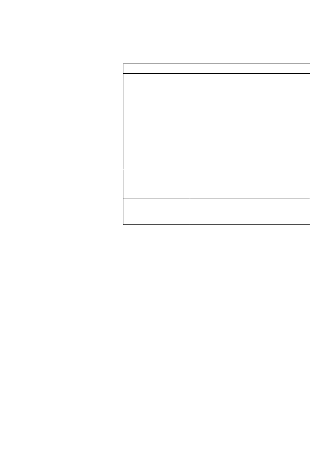
Table 2-1 Technical data of MOBY U (field components)
Fixed code memory MDS ID number (32 bits)
Read–only memory 128 bits, to be written once by the user
Application memory
Memory technology
Memory size
Memory organization
RAM
2 Kbytes or 32 Kbytes
File or address–oriented
Protection rating IP 67 to IP 68
Operational temperature –25 °C to +70/85 °C, 200 °C (cyclical),
220 °C (briefly)
Data transmission speed, SLG-MDS
(net) Without bunch With bunch size = 2
Write
Read Approx. 16.0 Kbyte/
sec
Approx. 14.4 Kbyte/
sec
Approx. 8.0 Kbyte/
sec
Approx. 7.2 Kbyte/
sec
Read/write distance 150 mm to 3000 mm
Can be connected to SIMATIC S7, PC, computer, other PLC,
PROFIBUS
SMDS: Mobile data memory
SSLG: Read and write device
SASM: Interface module
Primary
applications
Technical data
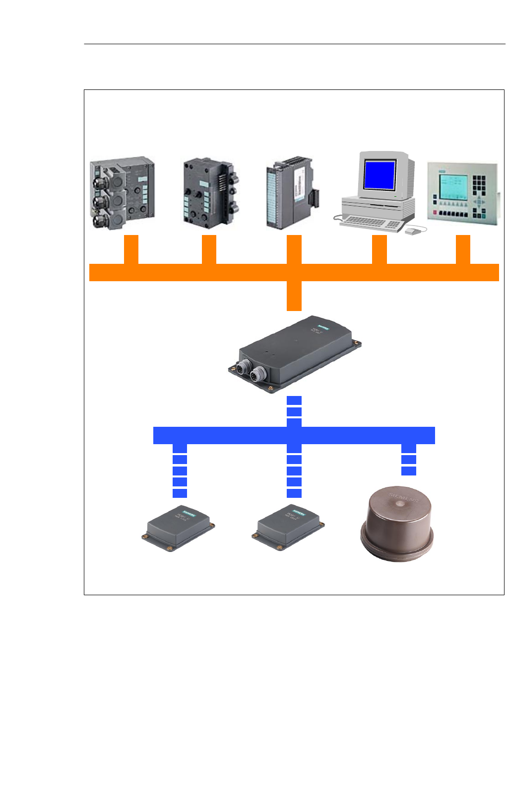
Overview of
the MOBY U
components
Introduction – MOBY U
2-4 MOBY U – Manual for Configuration, Installation and Service
(4) J31069-D0139-U001-A2-7618
ASM 452
for
SPROFIBUS-DPV1
SFC 45/FC 46
ASM 473
for
SET 200X
SFC 45/FC 56
ASM 475
for
SSIMATIC S7-300/
ET 200M
SFC 45/FC 56
PC/computer
SV.24/RS 422
SMOBY API
SICOMP/IMC
SV.24/RS 422
SMOBY API
Serial data transmission; max. of 115 kbit/sec
UHF data transmission, 2.45 GHz
SLG U92
with integrated
antenna
MDS U313
Logistics MDS U524
Production MDS U589
220 °C (cyclic)
Figure 2-1 Overview of the MOBY U components
Introduction – MOBY U
3-1
MOBY U – Manual for Configuration, Installation and Service
(4) J31069-D0139-U001-A2-7618
Configuration and Installation Guidelines 3

3-2 MOBY U – Manual for Configuration, Installation and Service
(4) J31069-D0139-U001-A2-7618
3.1 The Fundamentals
MOBY U is a UHF system with powerful features. This makes it much easier
to configure and handle the system.
SThe range (read/write distance) and communication speed are the same
for all data carriers. However, they do differ in memory size, operational
temperature and lifespan.
SReliable communication due to a homogenous transmission field with
circular polarization in dynamic and static operation. There is no fading
(i.e., temporary ”holes” in the field).
SThe range (0.15 m to 3 m) permits use throughout production.
SThe range of the transmission field can be limited (in increments) from
0.5 m to 3 m. This limitation prevents over–ranging and the communica-
tion range is clearly specified.
SFamiliar sources of interference during UHF transmissions such as reflec-
tion and interference have been removed with appropriate technical mea-
sures.
SDue to the transmission frequency and the robust modulation procedures,
electromagnetic sources of interference can be disregarded.
SSimple and flexible installation and customized system integration with
standard hardware and standard function blocks make commissioning fast
and easy.
SThe robust housing and the power–saving circuiting technology make for
years of maintenance–free operation even under the most rugged of pro-
duction environments.
SConflicts with other users of the 2.4 GHz frequency band are avoided by
using very low sending power (less than 50 mV per meter at 3-m inter-
vals) and automatic selection of free and interference–free frequency
channels.
Optimum utilization does require adherence to certain criteria.
STransmission window
STime that MDS is in the field (speed and amount of data) during dynamic
transmission
SMetal–free space and metallic environment around MDS and SLG
SAmbient conditions such as humidity, temperature, chemicals, and so on
SOther users of the frequency band at 2.4 GHz
SReadiness to communicate: Sleep-time, standby mode, antenna on/off
SBunch size for bunch/multitag
SSystem interface performance
SSLG synchronization
SProximity switches
Configuration and Installation Guidelines
3-3
MOBY U – Manual for Configuration, Installation and Service
(4) J31069-D0139-U001-A2-7618
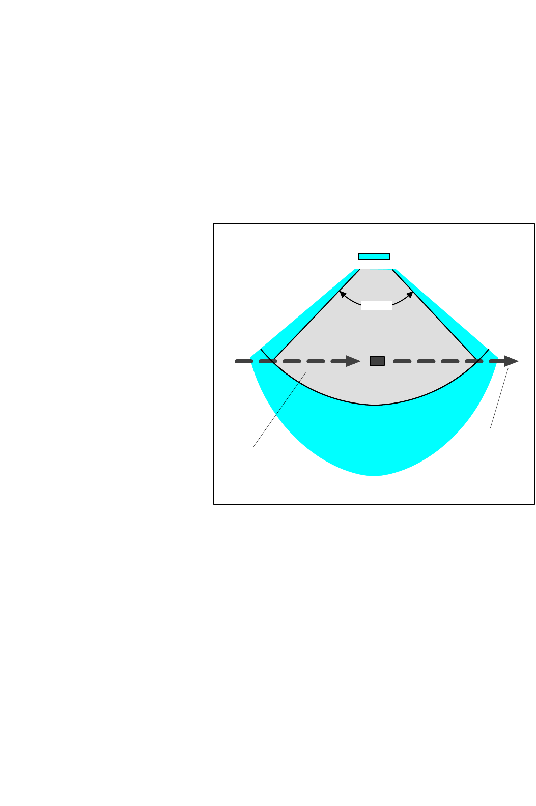
3.1.1 Transmission Window
MOBY U is a UHF system. UHF systems have a relatively wide range de-
spite their low emission power. However, the emission field has a directional
characteristic which depends on the antenna construction. MOBY U has vari-
ous function zones which depend on direction and distance to keep the
MDS’s power requirements low and to make localization reproducible. The
states and reactions of the affected components vary with the three different
zones of the transmission field (see figure 3-1).
SLG U92 with
integrated antenna
MDS
Zone 1: r = max. of 3.0 m
Can be adjusted in increments
Zone 2: r = up to approx. 5 m
Zone 3: r > approx.. 5 m or shielded
> 90°
Direction of
MDS’s
movement
Transmission
field
Figure 3-1 Status zones for MDS in transmission field of SLG U92
SZone 3:
In simplified terms, zone 3 is the UHF–free area. The MDS is asleep and
only wakes up once every < 0.5 sec to listen for an SLG. Power consump-
tion is very low. If other UHF users are in the vicinity and they are using
the same frequency range, this does not shorten the battery life of the
MDS since it does not wake up until it receives a special code.
Configuration and Installation Guidelines

3-4 MOBY U – Manual for Configuration, Installation and Service
(4) J31069-D0139-U001-A2-7618
SZone 2:
If the MDS receives this special code in the vicinity of an active SLG, it
enters zone 2 (see figure 3-1). Starting immediately it accepts the SLG
and responds briefly with its own ID. However, the SLG ignores all
MDSs which are not in zone 1 (radius can be parameterized on the SLG
in increments). Power consumption in zone 2 is a little higher than in
zone 3.
SZone 1:
When an MDS enters zone 1, it is registered by the SLG and can begin
exchanging data. All read and write functions can now be performed. The
power consumption of the MDS increases briefly during communication.
Since transmission through the air is very fast, total communication time
is very short. The entire 32–Kbyte data memory can be read in less than
four seconds. This means that data communication hardly uses the bat-
tery.
As long as the MDS is located in zone 1, it is ready to exchange data
when requested by the SLG. When no command for the MDS is queued,
it still reports at regular parameterizable intervals with its ID when re-
quested by the SLG. Its behavior corresponds to that of zone 2. Current
consumption drops again accordingly.
SWith MOBY U as a UHF system, the following physical characteristics
must be considered when you configure the system.
SThe waves in the UHF range spread out in straight lines.
SThe transmission field (zones 1 and 2) is shaped like an ellipse.
SThe range of the transmission ellipse up to 3 m can be adjusted in incre-
ments for better identification of the MDS.
SIn simplified terms, the transmission field can be thought of as a cone and
the midpoint of the antenna is located at the peak of this cone. The angle
of opening is approx. 90°. A primarily homogenous field is then assumed
within this parameterized area. Fading (temporary ”holes” in the field) in
this area is offset by technical measures.
SIdeally the MDS should penetrate the transmission cone of its basic sur-
face and exit through the surface area so that the MDS remains as long as
possible in the defined recording field.
SSince metallic surfaces reflect the waves, they can also be used for shield-
ing or even deflection. Particularly in typical production environments,
the wealth of metallic objects ensures a relatively uniform dispersion of
the transmission waves.
SFor optimum data communication, metal should be avoided at least in the
vicinity of the vertical waves.
SBoth the MDS and the SLG can be mounted directly on metal.
General
configuration rules
Configuration and Installation Guidelines

3-5
MOBY U – Manual for Configuration, Installation and Service
(4) J31069-D0139-U001-A2-7618
3.2 Basic Requirements
This device complies with part 15 of the FCC Rules.
Operation is subject to the following two conditions:
1. This device may not cause harmful interference.
2. This device must accept any interference received, including interference
that may cause undesired operation.
Note
Changes or modifications of this unit may void the user’s authority to oper-
ate the equipment.
FCC Compliance
Statement
Configuration and Installation Guidelines

3-6 MOBY U – Manual for Configuration, Installation and Service
(4) J31069-D0139-U001-A2-7618
3.3 EMC Guidelines
3.3.1 Preface
These EMC guidelines give you information on the following topics.
SWhy are EMC guidelines necessary?
SWhat outside interference affects the controller?
SHow can this interference be prevented?
SHow can this interference be corrected?
SWhich standards apply to EMC?
SExamples of interference–immune plant setup
This description is only meant for ”qualified personnel.”
SProject engineers and planners who are responsible for the plant configu-
ration with the MOBY modules and have to adhere to the applicable
guidelines
STechnicians and service engineers who have to install the connection
cables based on this description or correct malfunctions covered by these
guidelines
!Warning
Non–adherence to the highlighted information may cause hazardous states in
the plant. Individual components or the entire plant may be destroyed as a
result.
Configuration and Installation Guidelines

3-7
MOBY U – Manual for Configuration, Installation and Service
(4) J31069-D0139-U001-A2-7618
3.3.2 General
Increasing use of electrical and electronic devices creates the following situa-
tion.
SIncreasing density of the components
SIncreasing power electronics
SIncreasing switching speeds
SLower power consumption of the components
The more automation, the greater the danger of the devices interfering with
each other.
Electromagnetic compatibility (EMC) means the ability of an electrical or
electronic device to function correctly in an electromagnetic environment
without bothering its surroundings up to a certain degree.
EMC can be divided into three areas.
SOwn interference immunity
Immunity against internal (i.e., own) electrical interference
SFree interference immunity
Immunity against outside electromagnetic interference
SDegree of interference emission
Interference emission and influence of the electrical environment
All three areas must be considered when checking an electrical device.
The MOBY modules are checked for adherence to certain limit values. Since
the MOBY modules are only part of a total system and sources of interfer-
ence can be created just by combining different components, the setup of a
plant must adhere to certain guidelines.
EMC measures usually comprise a whole package of measures which must
all be taken to obtain an interference–immune plant.
Note
SThe constructor of the plant is responsible for adherence to the EMC
guidelines whereas the operator of the plant is responsible for radio inter-
ference suppression for the entire system.
SAll measures taken while the plant is being set up prevent expensive
modifications and removal of interference later on.
SNaturally, the country–specific rules and regulations must be adhered to.
They are not part of this documentation.
Configuration and Installation Guidelines
3-8 MOBY U – Manual for Configuration, Installation and Service
(4) J31069-D0139-U001-A2-7618
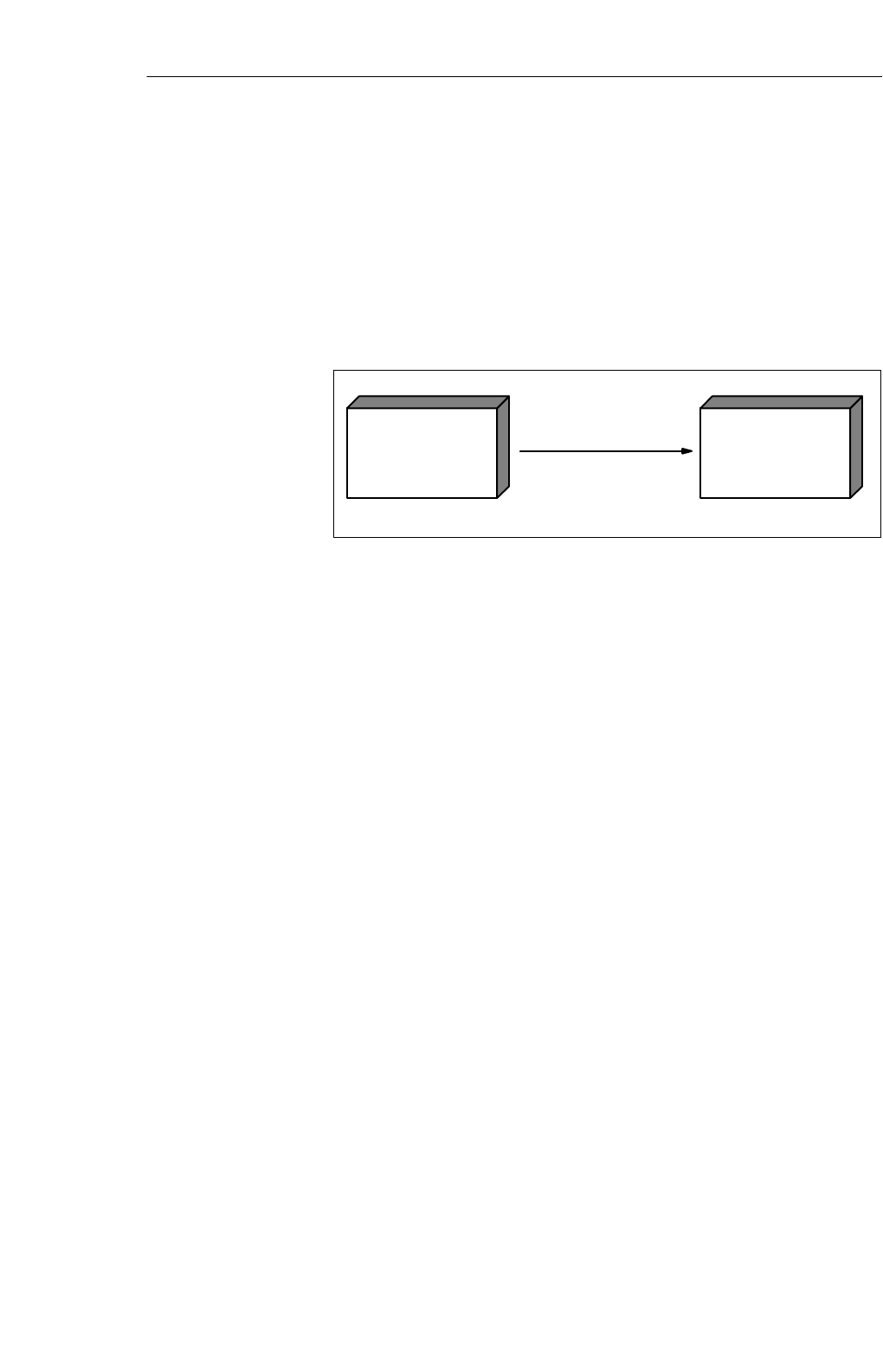
3.3.3 Spreading of Interference
The following three components must be present before interference can oc-
cur in a plant.
SSource of interference
SCoupling path
SPotentially susceptible equipment
Potential susceptible
equipment
(malfunctioning device)
Example: ASM 452
Source of interference
(instigator)
Example: Drive
Coupling path
Example: MOBY cable
Figure 3-2 Spreading of interference
If one of these components is missing (e.g., the coupling path between inter-
ference source and potentially susceptible equipment), the susceptible device
is not affected even when the source is emitting strong interference.
EMC measures affect all three components to prevent malfunctions caused
by interference. When setting up a plant, the constructor must take all pos-
sible precautions to prevent the creation of interference.
SOnly devices which meet limit value class A of VDE 0871 may be used
in a plant.
SAll interference–producing devices must be corrected. This includes all
coils and windings.
SThe cabinet must be designed to prevent mutual interference of the indi-
vidual components or keep this as low as possible.
SPrecautions must be taken to eliminate external interference.
The next few sections give you tips and hints on good plant setup.
Configuration and Installation Guidelines

3-9
MOBY U – Manual for Configuration, Installation and Service
(4) J31069-D0139-U001-A2-7618
To obtain a high degree of electromagnetic compatibility and thus a plant
with low interference, you must know the most frequent sources of
interference. These sources of interference must then be removed.
Table 3-1 Sources of interference: Origin and effects
Interference Source Interference Generator Effect on Susceptible
Equipment
Contactor, electronic
l
Contacts Network interference
valves Coils Magnetic field
Electric motor Collector Electrical field
Winding Magnetic field
Electric welding device Contacts Electrical field
Transformer Magnetic field, network interfe-
rence, equalizing current
Power pack, pulsed Circuit Electrical and magnetic field,
network interference
High–frequency devices Circuit Electromagnetic field
Transmitter
(e.g., plant radio) Antenna Electromagnetic field
Grounding or reference
potential difference Voltage difference Equalizing current
Operator Static charging Electrical discharge current,
electrical field
High–voltage cable Current flow Electrical and magnetic field,
network interference
High–voltage cable Voltage difference Electrical field
Sources of
interference
Configuration and Installation Guidelines
3-10 MOBY U – Manual for Configuration, Installation and Service
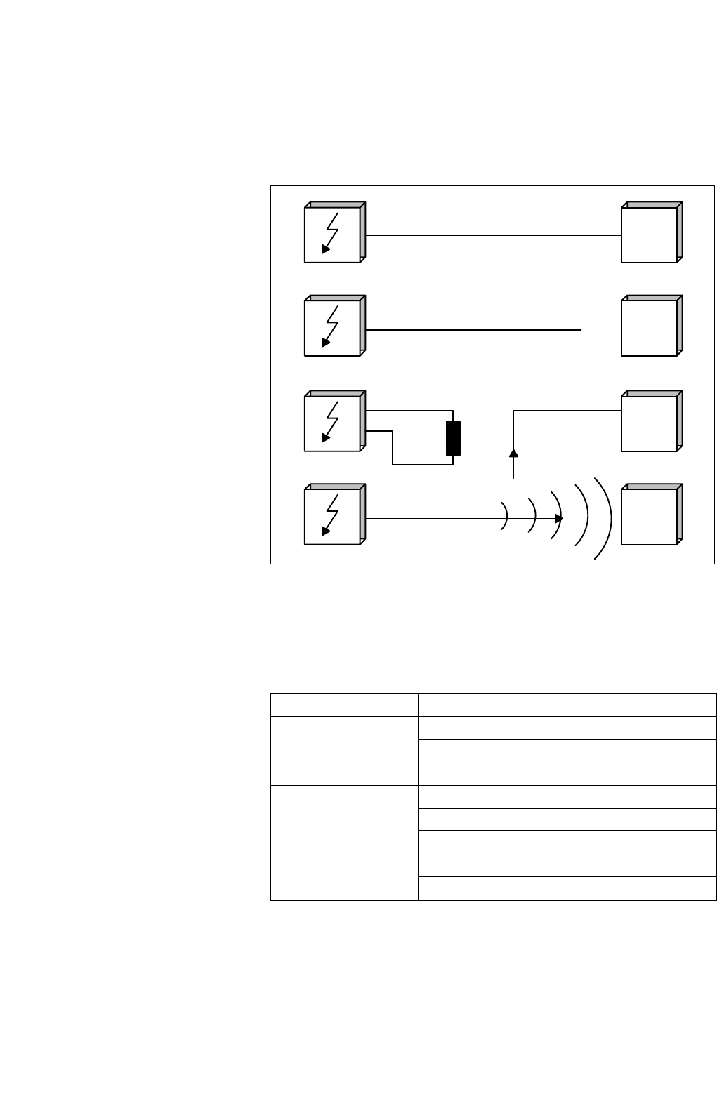
(4) J31069-D0139-U001-A2-7618
Before a source of interference can create actual interference, a coupling path
is needed. There are four types of interference coupling.
MOBY
ASM or
SLG
MOBY
ASM or
SLG
MOBY
ASM or
SLG
MOBY
ASM or
SLG
Galvanic coupling path
Capacitive coupling path
Inductive coupling path
Emission coupling
I
N
T
E
R
F
E
N
C
E
S
O
U
R
C
E
S
U
S
C
E
P
T
I
B
L
E
E
Q
U
I
P
M
E
N
T
Figure 3-3 Possible interference coupling
When MOBY modules are used, various components of the total system can
act as coupling paths.
Table 3-2 Causes of coupling paths
Coupling Path Caused by
Cables and lines Wrong or poor installation
Shield missing or connected incorrectly
Poor location of the cables
Switching cabinet or SI-
MATIC h i
Equalizing line missing or incorrectly wired
MATIC housing Grounding missing or faulty
Unsuitable location
Mounted modules not secure
Poor cabinet layout
Coupling paths
Configuration and Installation Guidelines
3-11
MOBY U – Manual for Configuration, Installation and Service
(4) J31069-D0139-U001-A2-7618
3.3.4 Cabinet Layout
User responsibility for the configuration of an interference–immune plant
covers cabinet layout, cable installation, grounding connections and correct
shielding of the cables.
Note
Information on EMC–proof cabinet layout can be taken from the setup
guidelines of the SIMATIC controller.
Magnetic and electrical fields as well as electromagnetic waves can be kept
away from susceptible equipment by providing a metallic housing. The better
induced interference current is able to flow, the weaker the interference field
becomes. For this reason all housing plates or plates in the cabinet must be
connected with each other and good conductivity ensured.
Figure 3-4 Shielding by the housing
When the plates of the switching cabinet are insulated against each other, this
may create a high–frequency–conducting connection with ribbon cables and
high–frequency terminals or HF conductive paste. The larger the connection
surface, the better the high–frequency conductivity. Connection of simple
wires cannot handle this task.
Shielding by
housing
Configuration and Installation Guidelines
3-12 MOBY U – Manual for Configuration, Installation and Service
(4) J31069-D0139-U001-A2-7618
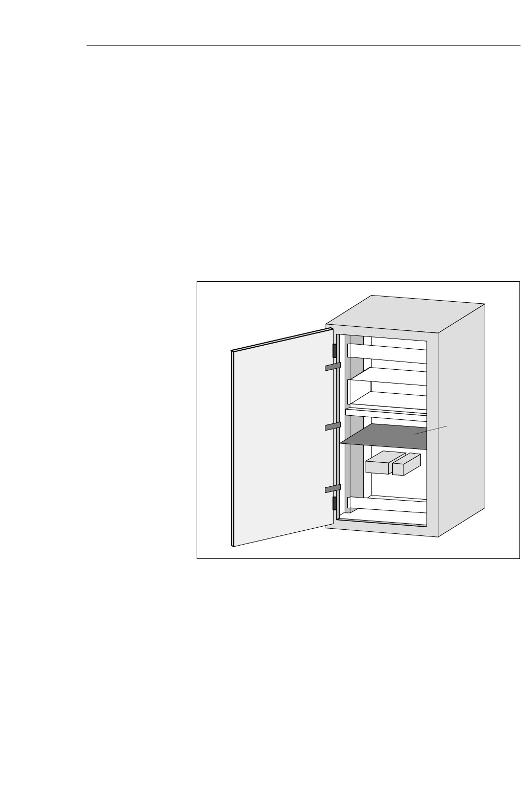
Installation of SIMATIC controllers on conductive mounting plates (not
painted) is a good way to get rid of interference. Adhering to the guidelines
when laying out the switching cabinet is a simple way to avoid interference.
Power components (transformers, drives, load power packs) should not be
located in the same room with controller components (relay control parts,
SIMATIC S5).
The following principles apply.
1. The effects of interference decrease the greater the distance between
source of interference and susceptible equipment.
2. Interference can be decreased even more by installing shielding plates.
3. Power lines and high–voltage cables must be installed separately at least
10 cm away from signal lines.
PS
Controller
Drive
Shield
plate
Figure 3-5 Avoidance of interference with optimal layout
Avoidance of
interference with
optimized layout
Configuration and Installation Guidelines
3-13
MOBY U – Manual for Configuration, Installation and Service
(4) J31069-D0139-U001-A2-7618
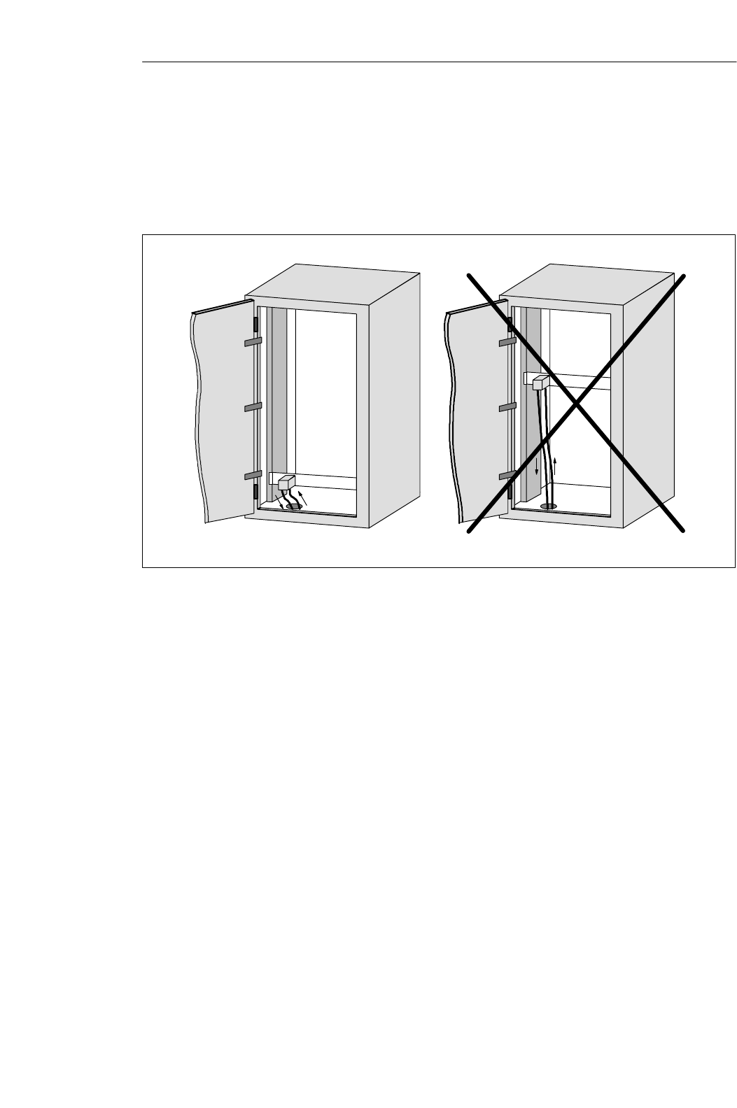
Power filters can be used to combat external interference over the power
network. In addition to correct dimensioning, proper installation is very
important. It is essential that the power filter be mounted directly on the
cabinet leadin. This keeps interference current from entering the cabinet by
filtering it out from the beginning.
Power filter
Is
Right
Power filter
Wrong
Is = Interference
current
Is
Figure 3-6 Filtering the voltage
Filtering the
voltage
Configuration and Installation Guidelines
3-14 MOBY U – Manual for Configuration, Installation and Service
(4) J31069-D0139-U001-A2-7618
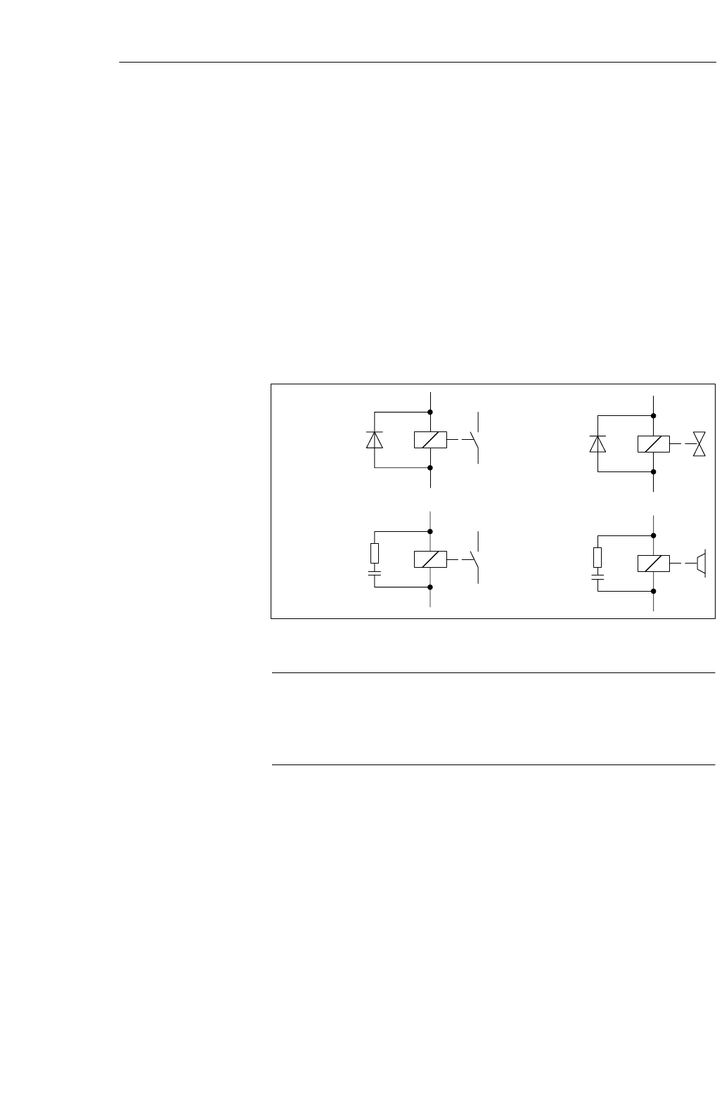
3.3.5 Avoiding Sources of Interference
Inclusion of interference sources in a plant must be avoided to achieve a
higher degree of interference immunity. All switched inductivity is frequent-
ly a source of interference in plants.
Relays, contactors, etc. generate interference voltages which must be
suppressed with one of the following circuits.
24 V coils create up to 800 V even with small relays and 220 V coils gener-
ate interference voltages of several kV when the coil is switched. Free wheel-
ing diodes or RC circuits can be used to prevent interference voltage and thus
also inductivity in lines which must be installed parallel to the coil line.
Relay coils
Contactors
Valves
Brakes
Figure 3-7 Suppression of inductivity
Note
All coils in the cabinet must be interference–suppressed. Don’t forget the
valves and motor brakes. A special check must be made for neon lamps in
the switching cabinet.
Suppression of
inductivity
Configuration and Installation Guidelines
3-15
MOBY U – Manual for Configuration, Installation and Service
(4) J31069-D0139-U001-A2-7618
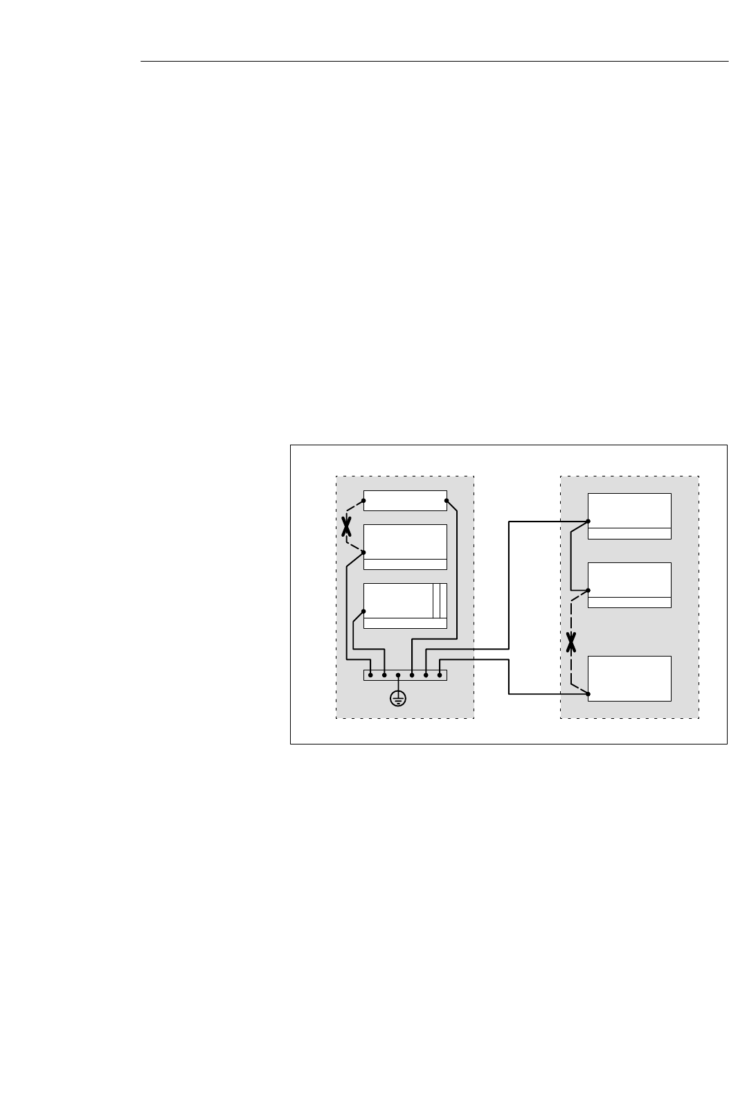
3.3.6 Equipotential Bonding
Differences in potential may be created between the parts of the plant by dif-
fering layout of plant parts and differing voltage levels. When the parts of the
plant are connected with signal lines, equalizing currents flow over the signal
lines. These equalizing currents may distort the signals.
This makes it very important to provide correct equipotential bonding.
SThe cross section of the equipotential bonding line must be large enough
(at least 10 mm2).
SThe distance between signal cable and equipotential bonding line must be
as short as possible (effects of antenna).
SA fine–wire line must be used (better high–frequency conductivity).
SWhen the equipotential bonding lines are connected to the central equipo-
tential bonding rail, power components and non–power components must
be combined.
Power pack
PLC
EU
EU
EU
Drive
Wrong
Wrong
Cabinet 1 Cabinet 2
Figure 3-8 Equipotential bonding
The better the equipotential bonding in a plant, the less interference is
created by potential fluctuations.
Don’t confuse equipotential bonding with the protective ground of a plant.
Protective ground prevents the creation of high touch voltages on defective
devices.
Configuration and Installation Guidelines
3-16 MOBY U – Manual for Configuration, Installation and Service
(4) J31069-D0139-U001-A2-7618
3.3.7 Shielding the Cables
To suppress interference coupling in the signal cables, these cables must be
shielded.
The best shielding is achieved by installation in steel tubing. However, this is
only required when the signal line has to be led through high interference.
Use of cables with braided shields is usually sufficient. In both cases, correct
connection is decisive for shielding.
Note
A shield which is not connected or is not connected correctly is not a shield.
The following principles apply.
SWith analog signals, the shield is connected on one side to the receiver
side.
SWith digital signals, the shield is applied on both sides to the housing.
SSince interference signals are frequently in the HF range (> 10 kHz), a
large–surface shield which meets HF requirements is needed.
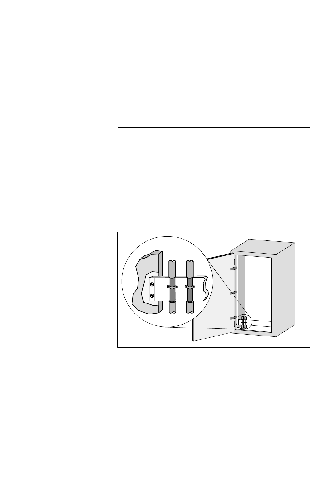
Figure 3-9 Shielding the cables
The shield bar must be connected (over a large surface for good conductivity)
to the switching cabinet housing. It must be located as close as possible to the
cable leadin. The cables are bared and then clamped to the shield bar (high–
frequency clamps) or bound with cable binders. Make sure that the connec-
tion is very conductive.
Configuration and Installation Guidelines
3-17
MOBY U – Manual for Configuration, Installation and Service
(4) J31069-D0139-U001-A2-7618
Remove
paint
Cable binder
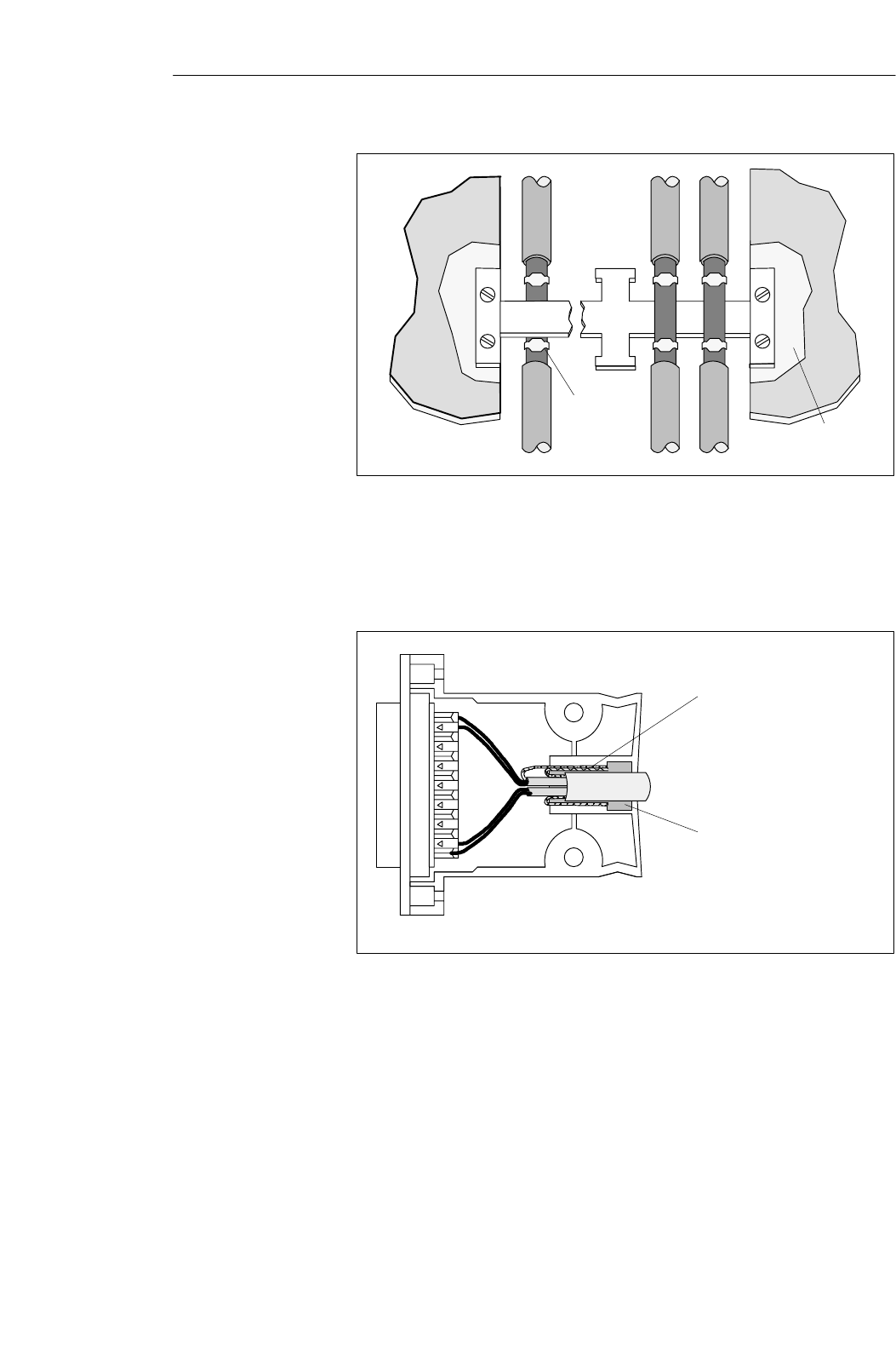
Figure 3-10 Connecting the shield bar
The shield bar must be connected with the PE bar.
If shielded cables have to be interrupted, the shield must be continued on the
plug case. Only suitable plug connectors may be used.
Fold back shield by 180° and
then connect with plug case.
Rubber sleeve
Figure 3-11 Interruption of shielded cables
If intermediate plug connectors which have no shield connection are used,
the shield must be continued with cable clamps at the point of interruption.
This gives you a large–surface, HF conductive connection.
Configuration and Installation Guidelines

3-18 MOBY U – Manual for Configuration, Installation and Service
(4) J31069-D0139-U001-A2-7618
3.3.8 Basic EMC Rules
Often the adherence to a few elementary rules is sufficient to ensure electro-
magnetic compatibility (EMC). The following rules should be observed when
setting up the switching cabinet.
SProtect the programmable controller from external interference by instal-
ling it in a cabinet or housing. The cabinet or housing must be included in
the grounding concept.
SShield the programmable controller from electromagnetic fields of induc-
tivity by using divider plates.
SUse metallic plug connector cases for shielded data transmission lines.
SConnect all inactive metallic parts over a large surface with low ohmic
HF.
SMake a large–surface connection between the inactive metallic parts and
the central grounding point.
SDon’t forget to include the shield bar in the grounding concept. This
means that the shield bar itself must be connected over a large surface
with ground.
SDo not use aluminum parts for grounding connections.
SDivide the cables into groups and install the groups separately.
SAlways install high–voltage cables and signal lines in separate ducts or
bundles.
SAlways have the entire cabling enter the cabinet on only one side and at
only one level.
SInstall the signal lines as close as possible to grounding surfaces.
STwist the ”to” and ”from” conductors of individual cables in pairs.
Shielding by the
housing
Surface–shaped
grounding
connection
Planning the cable
installation
Configuration and Installation Guidelines

3-19
MOBY U – Manual for Configuration, Installation and Service
(4) J31069-D0139-U001-A2-7618
SShield the data transmission cables and apply the shield on both sides.
SShield the analog cables and apply the shield on one side (e.g., on the
drive).
SAlways apply the cable shields over a large surface on the cabinet leadin
on the shield bar and affix these with clamps.
SContinue the applied shield without interruption up to the module.
SUse braided shields and not foil shields.
SUse only power filters with metal housing.
SConnect the filter housing (over a large surface and with low ohmic HF)
to cabinet ground.
SNever secure the filter housing on painted surfaces.
SSecure the filter on the cabinet’s entry point or in the direction of the
source of interference.
Shielding the
cables
Power and signal
filters
Configuration and Installation Guidelines
3-20 MOBY U – Manual for Configuration, Installation and Service
(4) J31069-D0139-U001-A2-7618
3.4 MOBY Shielding Concept
With MOBY U, the data are transferred between ASM and SLG at a speed of
19200, 38400, 57600 or 115200 Baud over an RS 422 interface. The distance
between ASM and SLG can be up to 1000 m. With respect to cabling,
MOBY should be handled like a data processing system. Special attention
should be paid to shield installation for all data cables. The following figures
shows the primary factors needed for a reliable setup.
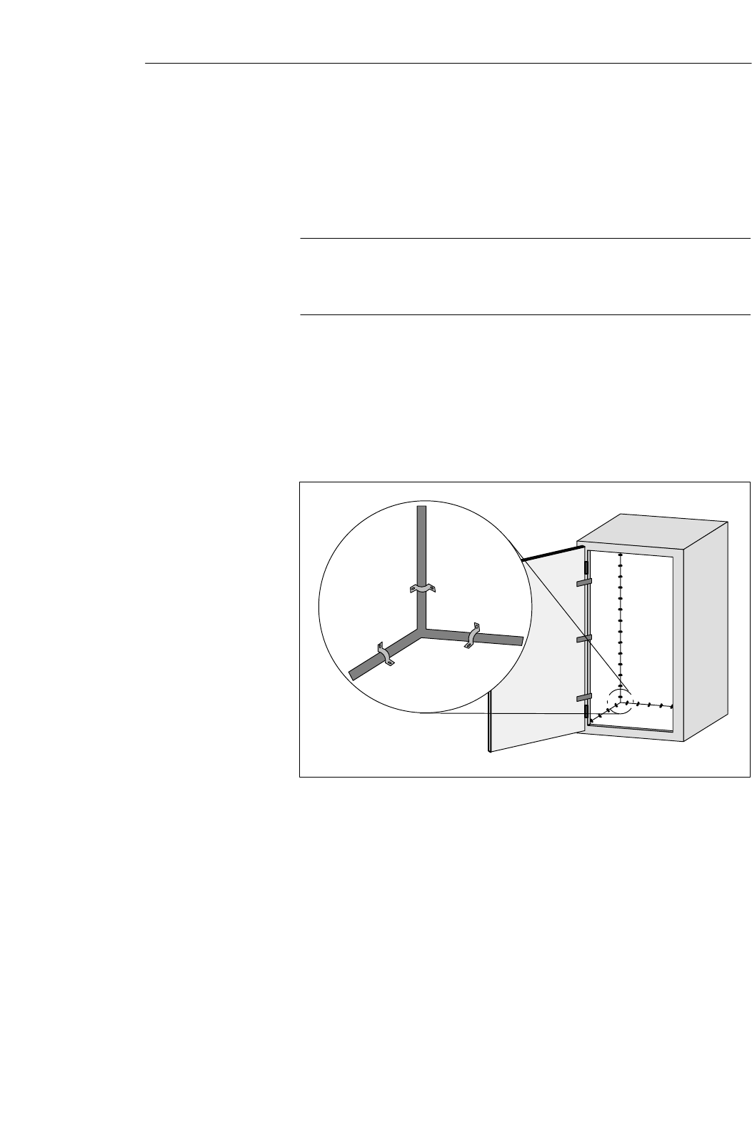
3.4.1 SLG Cable between ASM 475 and SLG U92 with RS 422
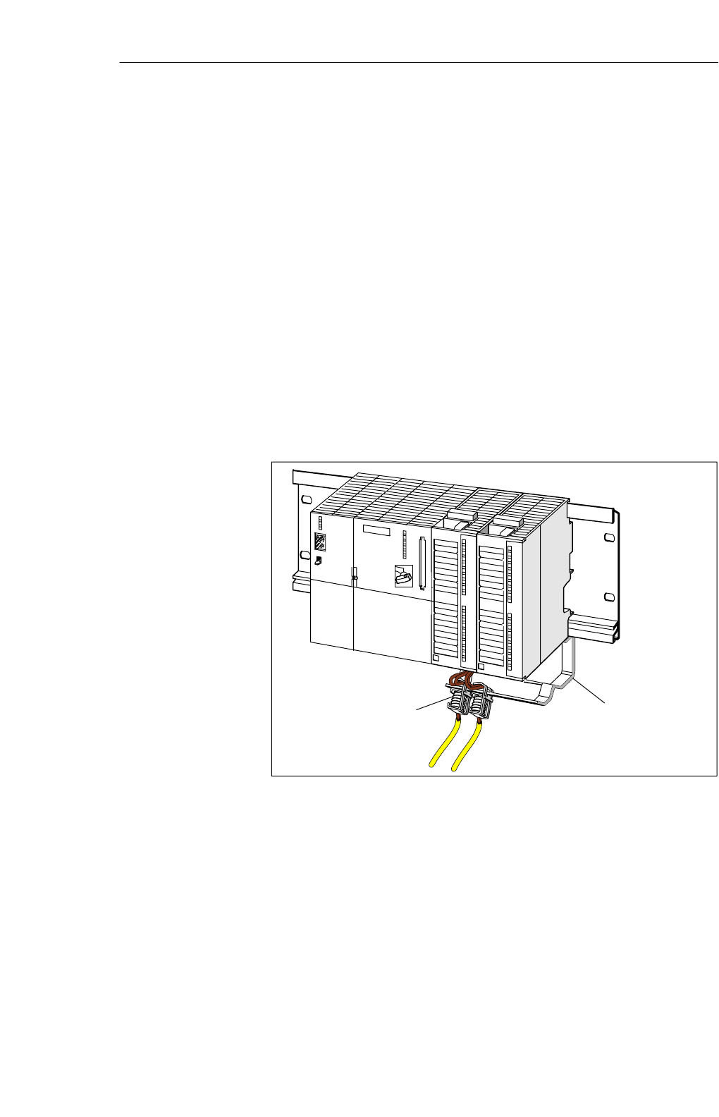
When the SLG U92 is connected to the ASM 475, it is essential to use a
shield connection terminal for the cable shield. Shield connection terminals
and holder brackets are standard components of the S7–300 product family.
Shield connection termi-
nal
Holding
bracket
Cable to SLG1 Cable to SLG2
Figure 3-12 Layout of the ASM 475 with shield connecting element
Layout of an
S7–300 with MOBY
Configuration and Installation Guidelines
3-21
MOBY U – Manual for Configuration, Installation and Service
(4) J31069-D0139-U001-A2-7618
3.5 SLG Cable and Plug Connector Allocations (RS 422)
The jacket used for MOBY SLG connection cables is made of polyurethane
(PUR in acc. w. VDE 0250). This gives the cables very good resistance to oil,
acid, lye and hydraulic fluid.
3.5.1 Cable Configuration
The cable between ASM and SLG has six cores plus shield. Four of these
cores are allocated to the serial data interface. The power supply of the SLG
requires two cores. Regardless of the wire diameter, data can usually be
transmitted up to a distance of 1000 m.
The voltage on the connection cable drops due to the power consumption of
the SLG. For this reason, the permitted cable length is usually shorter than
1000 m. It depends on the current consumption of the SLG and the ohmic
resistance of the connection cable. The following table gives you an over-
view of the permitted cable lengths.
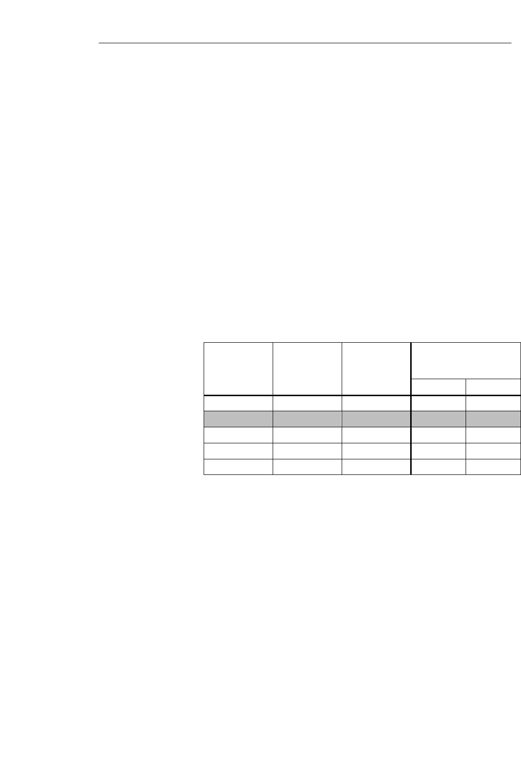
Table 3-3 Cable configuration
Conductor
Cross Section in
mm2
Conductor
Cross Section in
mm
Resistance
W/km1SLG U92 with RS 422
(I = 300 mA) Max. Cable
Length in m for
UV = 24 V UV = 30 V
0.0720.32550 30 70
0.2 0.5 185 85 210
0.5 0.8 70 230 570
0.821.0250 320 800
1.521.4224 660 1000
1 The resistance values are average values. They refer to the ”to” and ”from” conductors.
A single wire has half the specified resistance.
2 When these conductor cross sections are used, crimp contacts must be used in the SLG
connection plug. These crimp contacts are not included with the connection plugs.
Field highlighted in gray:
Standard cable recommended by Siemens (LiYC11Y, 6 x 0.25, shielded). The cable is
available from SIEMENS under the order number ”6GT2 090-0A...”.
We recommend always grounding the shield of the SLG cable over a large
surface to the grounding rail.
Grounding of the
SLG cable
Configuration and Installation Guidelines
3-22 MOBY U – Manual for Configuration, Installation and Service
(4) J31069-D0139-U001-A2-7618
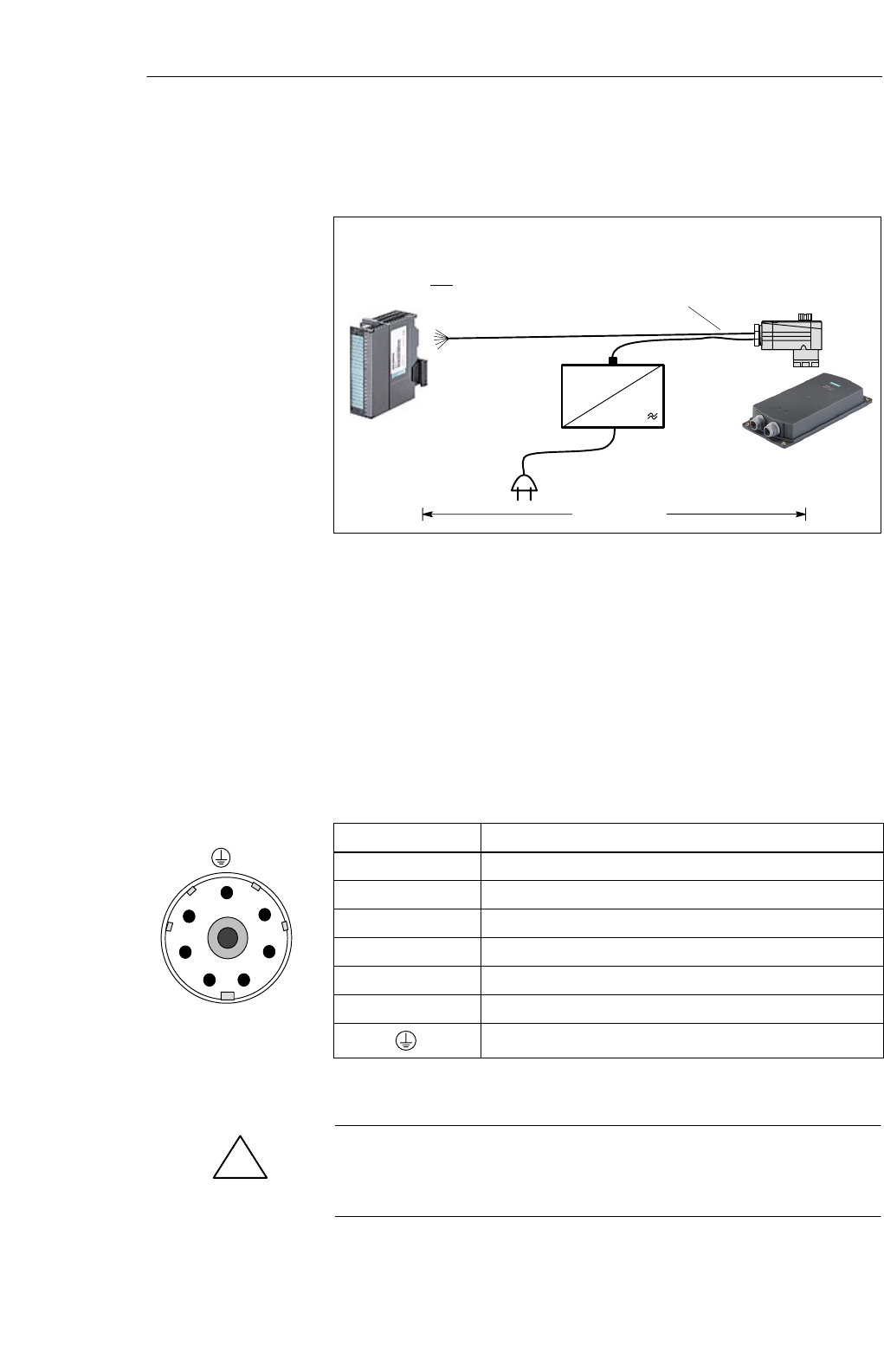
When an extra power pack is installed in the vicinity of the SLG, you can
always use the maximum cable length of 1000 m between ASM and SLG.
230 V
SLG
Max. of 1000 m
24 V =
6–core (with 24 V connection)
90 –
Note
The 24 V power supply (pin 2 on the SLG connector)
may not be connected to the ASM.
Figure 3-13 SLG with extra power pack
The power pack in our drawing can be obtained from Siemens under the
number 6GT2 494-0AA00 (see chapter 7.2).
The cable from the extra power pack to the SLG must be provided by the
customer.
3.5.2 Plug Connector Allocations
Table 3-4 Plug connector allocation of the SLG connector
Pin Name
1- Receive
2+24 Volt
3Ground (0 V)
4+ Send
5- Send
6+ Receive
Cable shield
!Caution
When the extra power pack is used in the vicinity of the SLG, do not wire
the +24 V pin to the ASM. (Cf. table 3-4.)
Extra power pack
for SLG
1
6
5
4
3
2
Plug on SLG
Configuration and Installation Guidelines
3-23
MOBY U – Manual for Configuration, Installation and Service
(4) J31069-D0139-U001-A2-7618
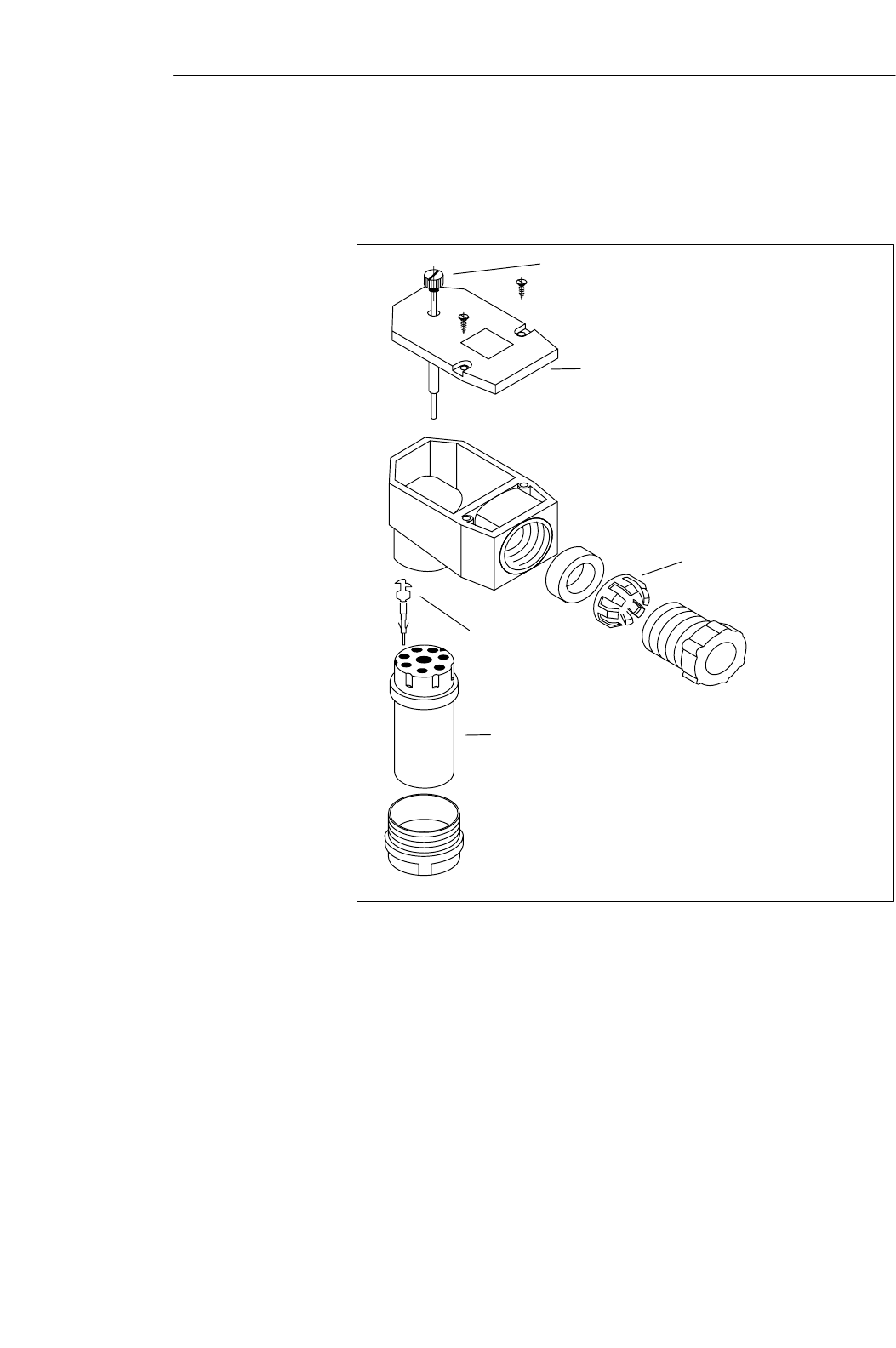
If the user has to turn the SLG plug of a prefabricated cable in a different
direction, follow the diagram below and position the contact carrier
differently. The plug connector on the SLG cannot be turned.
Knurled screw for
vibration–proof connections
(no tools required)
Removable housing cover
for easy mounting
Cable holder with cage claw
Crimp contacts
for use with
strong vibration*
Contact carrier must be
affixed at 7 positions.
* Manual crimp pliers: order from:
Hirschmann,
72606 Nürtingen
Tel. 07127/14-1479;
Type XZC0700,
Order no.: 932 507-001
Figure 3-14 Drawing of how to mount the SLG plug connector
Installing the SLG
plug connector
Configuration and Installation Guidelines
3-24 MOBY U – Manual for Configuration, Installation and Service
(4) J31069-D0139-U001-A2-7618
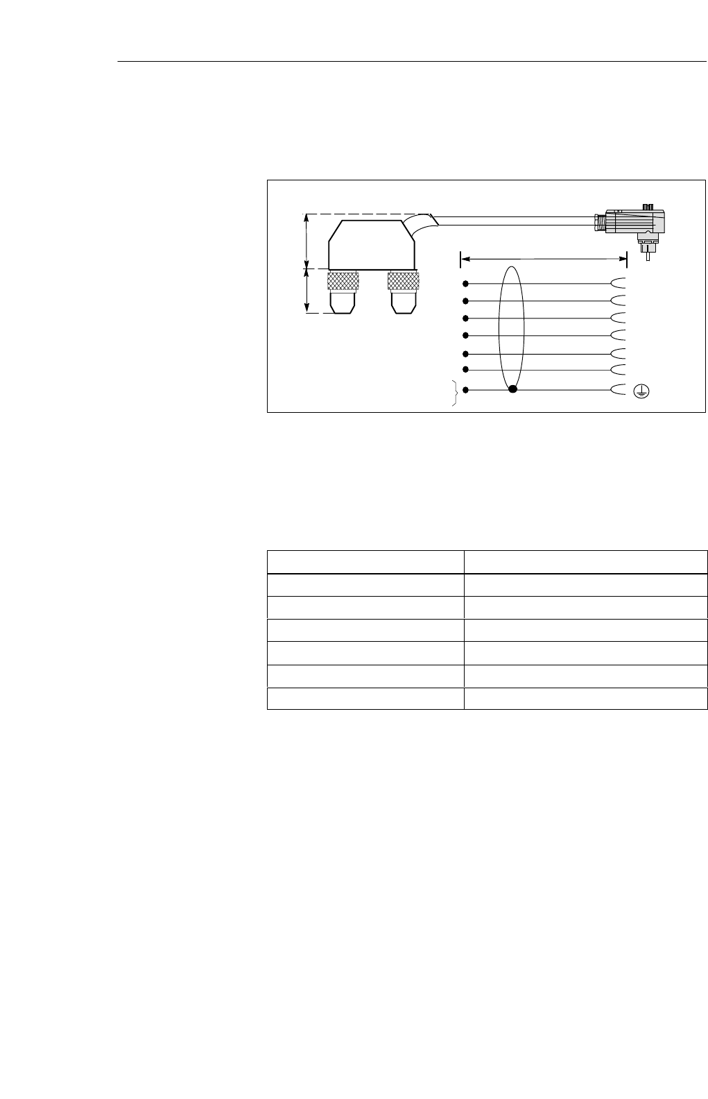
3.5.3 Connection Cables
6
1
4
5
3
2
Two 5–pin, round M12 plug
connectors
X1/2
X1/3
X1/1
X1/4
X2/3
X2/1
X1/5
X2/5
x1 X2
White
Brown
Green
Yellow
Gray
Pink
SLG plug (socket)
2m
22.5
18.5
Figure 3-15 Connection cable ASM 452/473 ↔ SLG U92 with RS 422
The connection cable can be ordered in the following lengths.
Table 3-5 Cable lengths of ASM 475 ↔SLG U92 with RS 422
Length of Stub Line in m Order Number
216GT2 091-1CH20
56GT2 091-1CH50
10 6GT2 091-1CN10
20 6GT2 091-1CN20
50 6GT2 091-1CN50
226GT2 091-2CH20
1 Inexpensive standard length
2 Connection cable with straight SLG plug
Connection cable
ASM 452/473 ↔
SLG U92 with
RS 422
6GT2 091-1C...
Configuration and Installation Guidelines
3-25
MOBY U – Manual for Configuration, Installation and Service
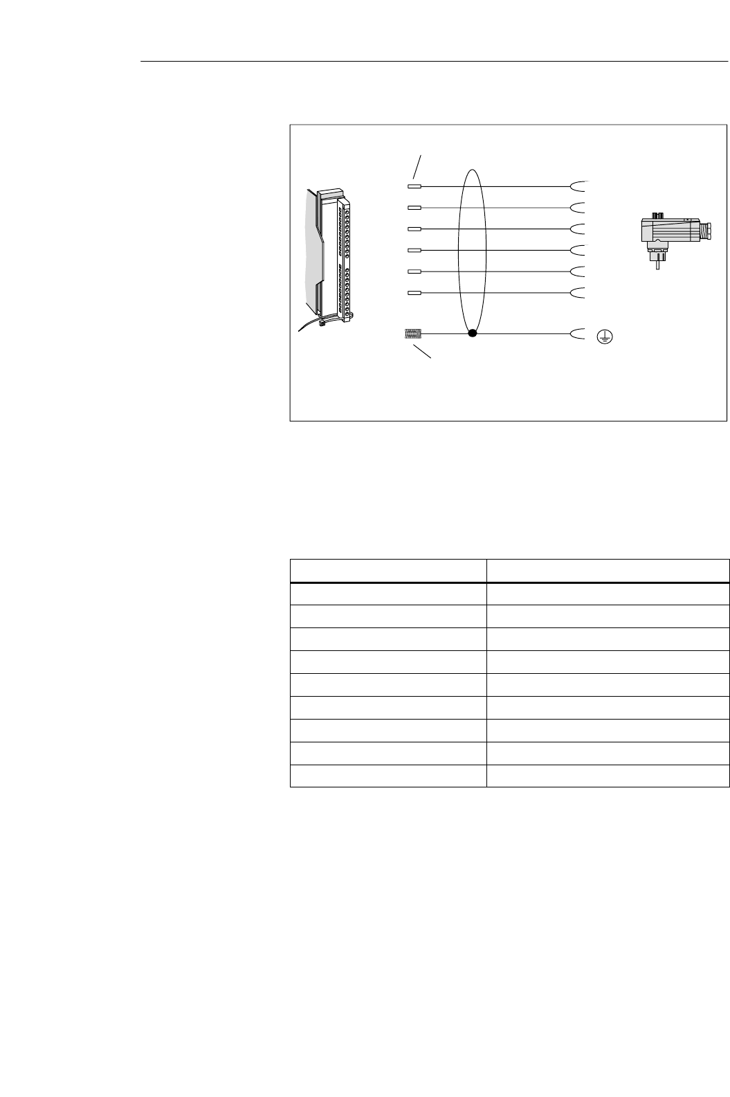
(4) J31069-D0139-U001-A2-7618
SLG plug
(socket)
Cable with core sleeves
White
Brown
Green
Yellow
Pink
Gray
(Shield)
6
1
4
5
2
3
4 (12)
5 (13)
6 (14)
7 (15)
8 (16)
9 (17)
Cable shield open
16GT2
091-0E... with angled SLG plug (standard)
6GT2 091-2E... with straight SLG plug (not shown)
1
Figure 3-16 Connection cable ASM 475 ↔ SLG U92 with RS 422
The connection cable can be ordered in the following lengths.
Table 3-6 Cable lengths of ASM 475 ↔SLG U92 with RS 422
Length of Stub Line in m Order Number
26GT2 091-0EH20
56GT2 091-0EH50
10 6GT2 091-0EN10
20 6GT2 091-0EN20
50 6GT2 091-0EN50
216GT2 091-2EH20
516GT2 091-2EH50
1016GT2 091-2EN10
5016GT2 091-2EN50
1 With straight SLG plug
Connection cable
ASM 475 ↔
SLG U92 with
RS 422
6GT2 091-0E...
Configuration and Installation Guidelines
3-26 MOBY U – Manual for Configuration, Installation and Service
(4) J31069-D0139-U001-A2-7618
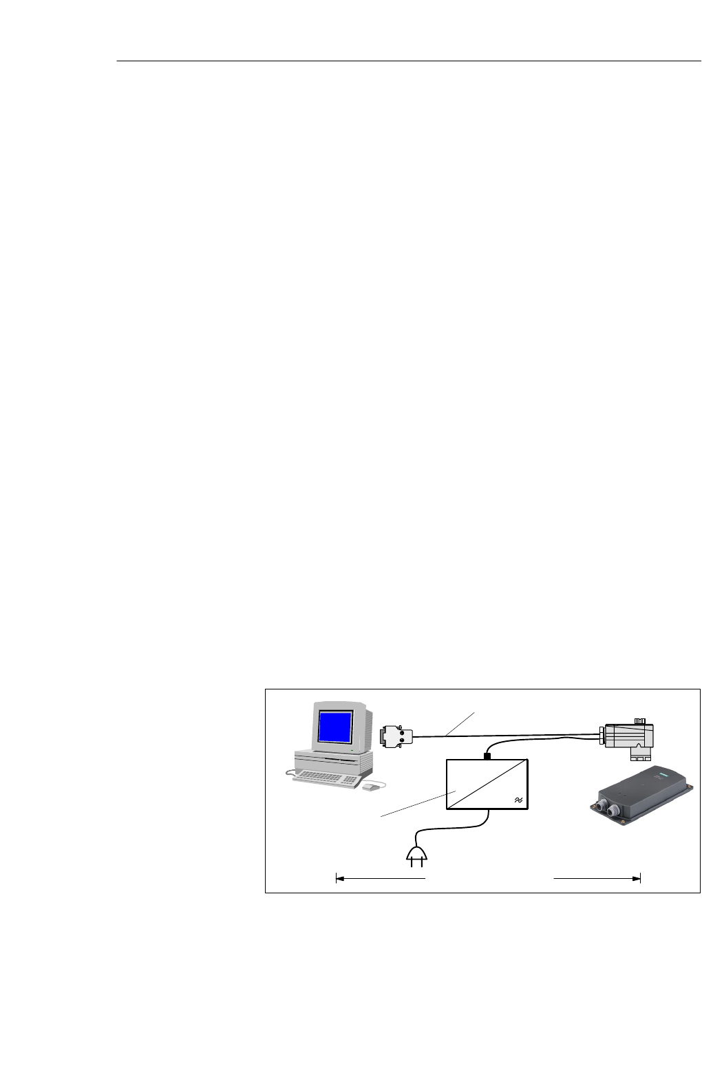
3.6 SLG Cable and Plug Allocations (RS 232)
With MOBY U, the data are transferred between PC and SLG at a speed of
19200, 38400, 57600 or 115200 Baud over an RS 232 interface. The distance
between PC and SLG can be up to 32 m.
The SLG cable is comprised of a stub line between PC and SLG and a con-
nection line for the 24 V power supply of the SLG from a standard power
pack (see chapter. 7.2).
SThe connection line for the power supply has a fixed length of 5 m.
SThe stub line between PC and SLG is available in two lengths (5 m and
20 m).
The connection cable for the power supply can be extended with a stub line
(order number 6GT2494-0AA0).
The jacket used for MOBY SLG connection cables is made of polyurethane
(PUR in acc. w. VDE 0250). This gives the cables very good resistance to oil,
acid, lye and hydraulic fluid.
3.6.1 Cable Configuration
The RS 232 cable between PC and SLG has three cores plus shield. The
cable for the power supply of the SLG requires two cores.
We recommend always grounding the shield of the SLG cable over a large
surface to the grounding rail.
230 V
SLG
Max. of 32 m (with RS 232)
24 V =
90 –
6GT2 494-0AA00
6GT2 591-1C...
Figure 3-17 Wide–range power pack for SLG U92
The power pack in our drawing can be obtained from Siemens under the
number 6GT2 494-0AA00 (see chapter 7.2).
Grounding of the
SLG cable
Power pack for
SLG U92
Configuration and Installation Guidelines
3-27
MOBY U – Manual for Configuration, Installation and Service
(4) J31069-D0139-U001-A2-7618
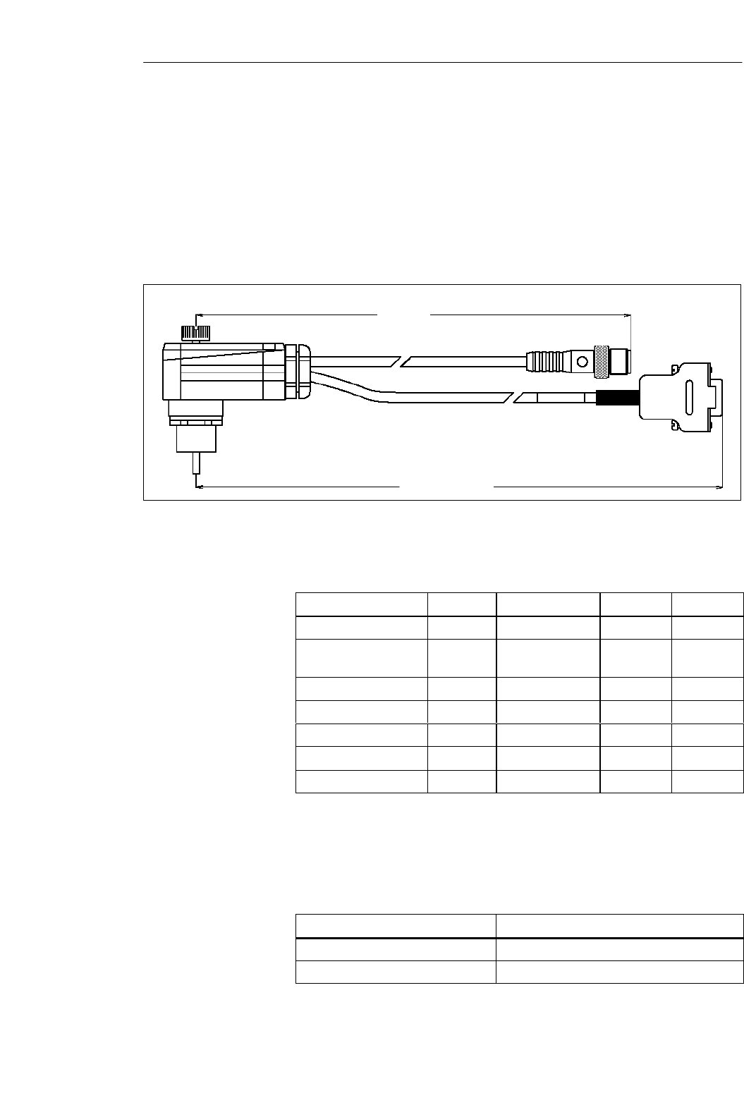
3.6.2 Connection Cables with Lengths
5 m
5/20 m
N6RFFR
KVPG11 Sensor 763
FPGHR
LIY11Y-6x0,25
5x RBC162/1AG
Nameplate
Sub D 9B
1x RBC162AG
Figure 3-18 Connection cable for PC ↔ SLG U92
Table 3-7 Plug allocation of SLG plug and submin D plug
SLG (RS 232) N6RFFR Sensor 763 (Pin) LIYC11Y Sub D 9B
GND 1 Green 5 (GND)
Vdc+ (power +) 22 (24 V DC)
white
Vdc– (power –) 31 (GND) brown
TxD (send data) 4 White 2 (RxD)
n.c. 5
RxD (receive data) 6 Brown 3 (TxD)
Shield GND Shield Housing
The connection cable can be ordered in the following lengths.
Table 3-8 Cable lengths for PC ↔ SLG U92 with RS 232
Length of Stub Line in m Order Number
56GT2 591-1CH50
20 6GT2 591-1CN20
Connection cable
for PC e SLG U92
with RS 232
6GT2 591-1C...
Configuration and Installation Guidelines

3-28 MOBY U – Manual for Configuration, Installation and Service
(4) J31069-D0139-U001-A2-7618
Users who want to make their own cables can order the following
components from the MOBY catalog.
Table 3-9 Components for individually fabricated cables
Component Order Number
SLG connection plug with screw ter-
minals with angled output 6GT2 090-0BA00
SLG stub line;
Type: 6 x 0.25 mm26GT2 090-0AN50 (50 m)
6GT2 090-0AT12 (120 m)
6GT2 090-0AT80 (800 m)
M12 socket
for extension of the 24 V cable 6GT2 390-1AB00
Non prefabricated
cables
Configuration and Installation Guidelines

3-29
MOBY U – Manual for Configuration, Installation and Service
(4) J31069-D0139-U001-A2-7618
3.7 Service Cable and Plug Allocations
3.7.1 Cable Configuration
3.7.2 Plug Allocations
3.7.3 Connection Cables with Lengths
Configuration and Installation Guidelines

3-30 MOBY U – Manual for Configuration, Installation and Service
(4) J31069-D0139-U001-A2-7618
Configuration and Installation Guidelines
4-1
MOBY U – Manual for Configuration, Installation and Service
(4) J31069-D0139-U001-A2-7618
Mobile Data Memories 4
4-2 MOBY U – Manual for Configuration, Installation and Service
(4) J31069-D0139-U001-A2-7618
4.1 Introduction
MOBY identification systems ensure that a product is accompanied by
meaningful data from the beginning to the end.
First, mobile data memories are affixed to the product or its carrier or its
packaging, then conductively written, changed and read. All information on
production and material flow control is located right on the product. Its
robust construction permits use in rugged environments and makes the MDS
insensitive to many chemical substances.
The primary components of mobile data memories (MDSs) are logic, an
antenna, a data memory and a battery.
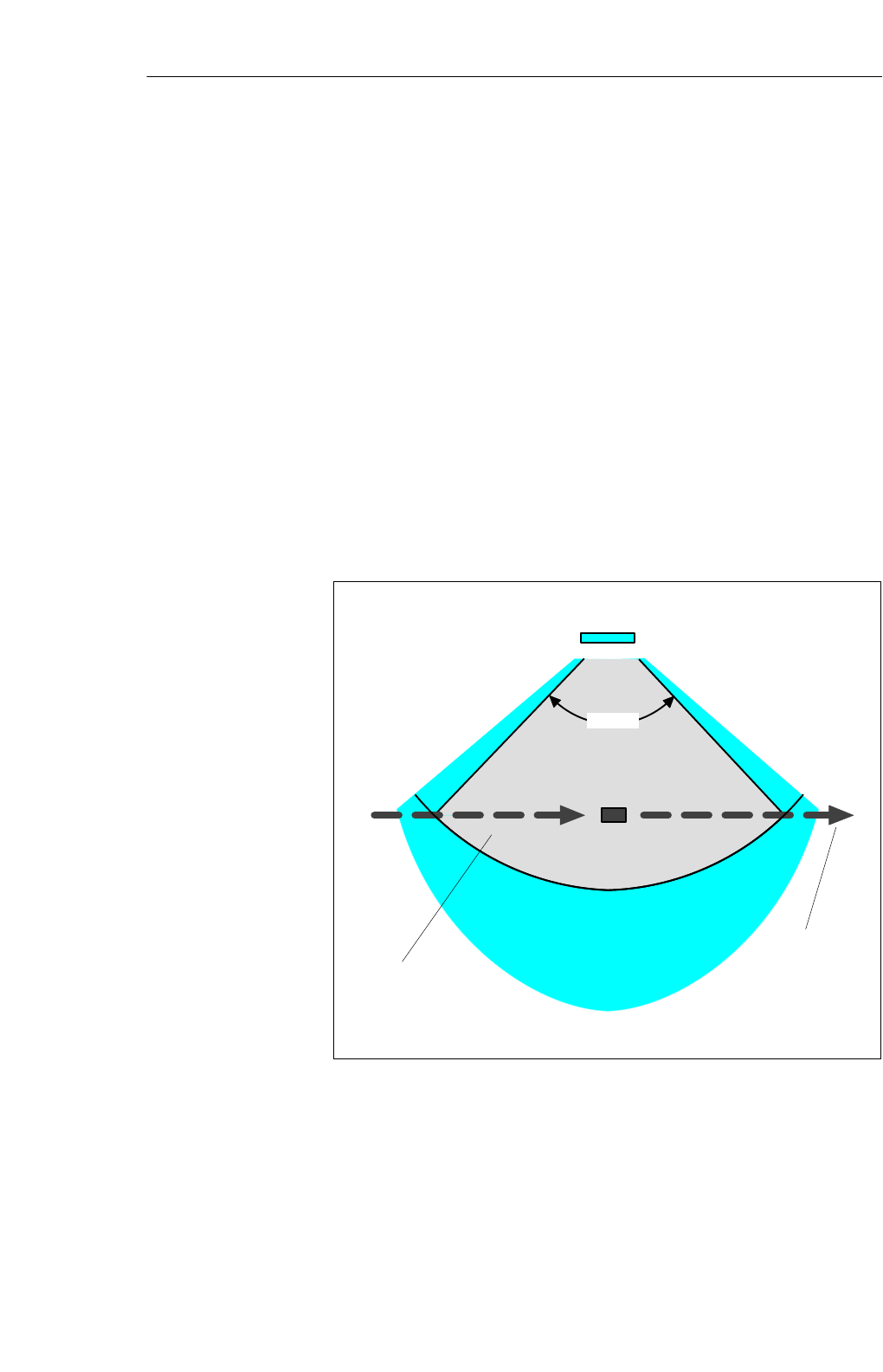
To keep the MDS’s power consumption low and make localization
reproducible, MOBY U has different function zones based on direction and
distance. The three different zones of the transmission field (see figure 4-1)
represent different states and reactions of the affected components.
SLG U92 with
integrated antenna
MDS
Zone 1: r = max. of 3.0 m
Can be adjusted in increments
Zone 2: r = up to approx. 5 m
Zone 3: r > approx. 5 m or shielded
> 90°
Direction of
MDS’s
movement
Transmission
field
Figure 4-1 Status zones for MDS in transmission field of SLG U92
Application area
Construction and
functions
Mobile Data Memorie
s

4-3
MOBY U – Manual for Configuration, Installation and Service
(4) J31069-D0139-U001-A2-7618
SZone 3:
In simplified terms, zone 3 is the UHF–free area. The MDS is asleep and
only wakes up to listen for an SLG once every < 0.5 sec. Power consump-
tion is very low. If other UHF users are in the vicinity and they are using
the same frequency range, this does not shorten the battery life of the
MDS since it does not wake up until it receives a special code.
SZone 2:
If the MDS receives this special code in the vicinity of an active SLG, it
enters zone 2 (see figure 4-1). Starting immediately it accepts the SLG
and responds briefly with its own ID. However, the SLG ignores all
MDSs which are not in zone 1 (radius can be parameterized on the SLG
in increments). Power consumption in zone 2 is a little higher than in
zone 3.
SZone 1:
When an MDS enters zone 1, it is registered by the SLG and can begin
exchanging data. All read and write functions can now be performed. The
power consumption of the MDS increases briefly during communication.
Since transmission through the air is very fast, total communication time
is very short. The entire 32–Kbyte data memory can be read in less than
four seconds. This means that data communication hardly uses the bat-
tery.
As long as the MDS is located in zone 1, it is ready to exchange data
when requested by the SLG. When no command for the MDS is queued,
it still reports at regular parameterizable intervals with its ID (sleep–time,
similar to t–ABTAST with MOBY I) when requested by the SLG. Its
behavior corresponds to that of zone 2. Current consumption drops again
accordingly.
Mobile Data Memorie
s
4-4 MOBY U – Manual for Configuration, Installation and Service
(4) J31069-D0139-U001-A2-7618
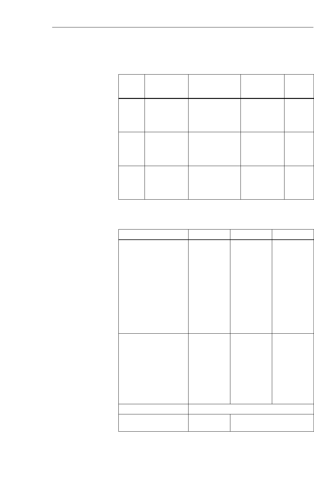
Table 4-1 Overview of the MDS
MDS
Type Memory Size Temperature Range
(during Operation) Dimensions
L x W x H
(in mm)
Protection
Rating
MDS
U313 2–Kbyte RAM
32–bit fixed code
128–bit read–
only memory
–25 to +70 °C111 x 67 x 23.5 IP 67
MDS
U524 32–Kbyte RAM
32–bit fixed code
128–bit read–
only memory
–25 to +85 °C111 x 67 x 23.5 IP 68
MDS
U589 32–Kbyte RAM
32–bit fixed code
128–bit read–
only memory
–25 to +220 °C
(cyclic) Ø 30 x 10 IP 68
Table 4-2 Operational/ambient conditions of the MDS
MDS U313 MDS U524 MDS U589
Proof of the physical strength
is provided by the vibration
test in acc. w. DIN EN
721-3-7, class 7 M3
Test conditions
SFrequency range
SAmplitude of the dis-
placement
SAcceleration
STest duration per axis
SSpeed of passage
Proof of the physical strength
is provided by the continuous
shock test in acc. w. DIN EN
721-3-7, class 7 M3
Test conditions
SAcceleration
SDuration
STest duration per axis
Torsion and bending stress Not permitted
Protection rating in acc. w.
EN 60529 IP 67 IP 68
Overview
Operational/ambie
nt conditions
Mobile Data Memorie
s
4-5
MOBY U – Manual for Configuration, Installation and Service
(4) J31069-D0139-U001-A2-7618
Table 4-2 Operational/ambient conditions of the MDS
MDS U589MDS U524MDS U313
Ambient temperature
SDuring operation in acc.
w.
EN 60 721-3-7,
class 7 K4
–25 to +70 °C –25 to +85 °C–25 to +220 °C
(cyclic)
SDuring transportation
and storage in acc. w.
EN 60 721-3-7,
class 7 K3
–40 to +85 °C –40 to +85 °C –40 to +85 °C
Temperature gradient over
storage temperature range, in
acc. w. DIN IEC 68, part
2-14
3 °C/min
Temperature gradient with
fast temperature change in
acc. w.
DIN IEC 68, part 2-14
Change from 0 °C to 70 °C (85 °C) in 10 sec;
Duration: 30 min;
Change from 70 °C (85 °C) to 0 °C in 15 sec;
100 cycles
Cleaning with water jet –Max. of 5 min at
max. of 2 bar
Chemical resistance
Definition of IP 67
– Protection against penetration of dust (dustproof)
– Total protection against accidental touch
– Protection against stream of water
Definition of IP 68:
– Protection against penetration of dust (dustproof)
– Total protection against accidental touch
– The MDS can be continuously submerged in water. Ask manufacturer for condi-
tions.
Mobile Data Memorie
s
4-6 MOBY U – Manual for Configuration, Installation and Service
(4) J31069-D0139-U001-A2-7618
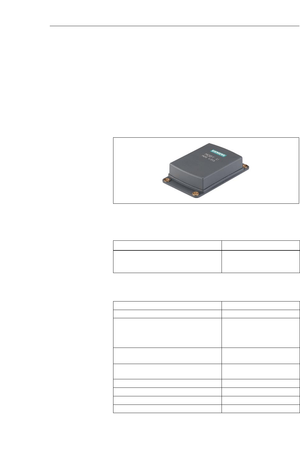
4.2 MDS U313
The MDS U313 is a mobile data memory (MDS) with a storage capacity of 2
Kbytes for use in transportation and logistics. The particularly low current
consumption guarantees a long life of 5 years. The interference–immune and
robust MDS can be read and written at a maximum distance of 3 m. The
MDS U313 is addressed directly with byte memory accesses. The transmis-
sion frequency in the ISM frequency band at 2.4 GHz makes the MDS’s net
data transmission speed very fast (up to 16 Kbyte/sec without multitaging
and up to 8 Kbyte/sec with multitaging of two MDSs).
Figure 4-2 MDS U313
Table 4-3 Ordering data for the MDS U313
Order No.
MDS U313 mobile data memory with 2–Kbyte
RAM, MDS ID number (32 bits), read–only me-
mory (128 bits)
6GT2500-3BD10
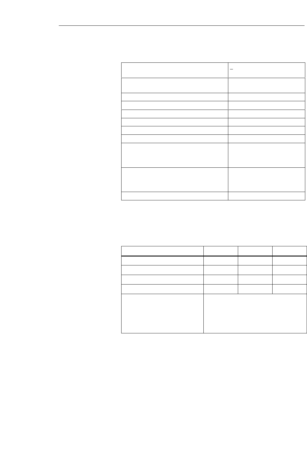
Table 4-4 Technical data of the MDS U313
Fixed code memory MDS ID number (32 bits)
Read–only memory 128 bits, to be written once by user
Application memory
Memory technology
Memory size
Memory organization
RAM
2 Kbytes
Byte access
Data retention time 10 years
MTBF (at +40°C) 2.5 x 10⁶ hours (without conside-
ring battery)
Read/write distance 0.15 m up to 3 m
Depends on direction No
Multitaging capability Yes
Power supply Battery
Ordering data
Technical data
Mobile Data Memorie
s
4-7
MOBY U – Manual for Configuration, Installation and Service
(4) J31069-D0139-U001-A2-7618
Table 4-4 Technical data of the MDS U313
Battery lifespan > 5 years at 25°C1); no replace-
ment
Shock, vibration in acc. w. DIN EN 721-3-7,
class 7 M3 50 g/10 g
Free fall 1 m
Mounting 4 M4screws
Tightening moment (at room temperature) v 0.8 Nm
Recommended distance from metal Can be mounted directly on metal
Protection rating in acc. w. EN 60529 IP 67
Chemical resistance See table 4-2.
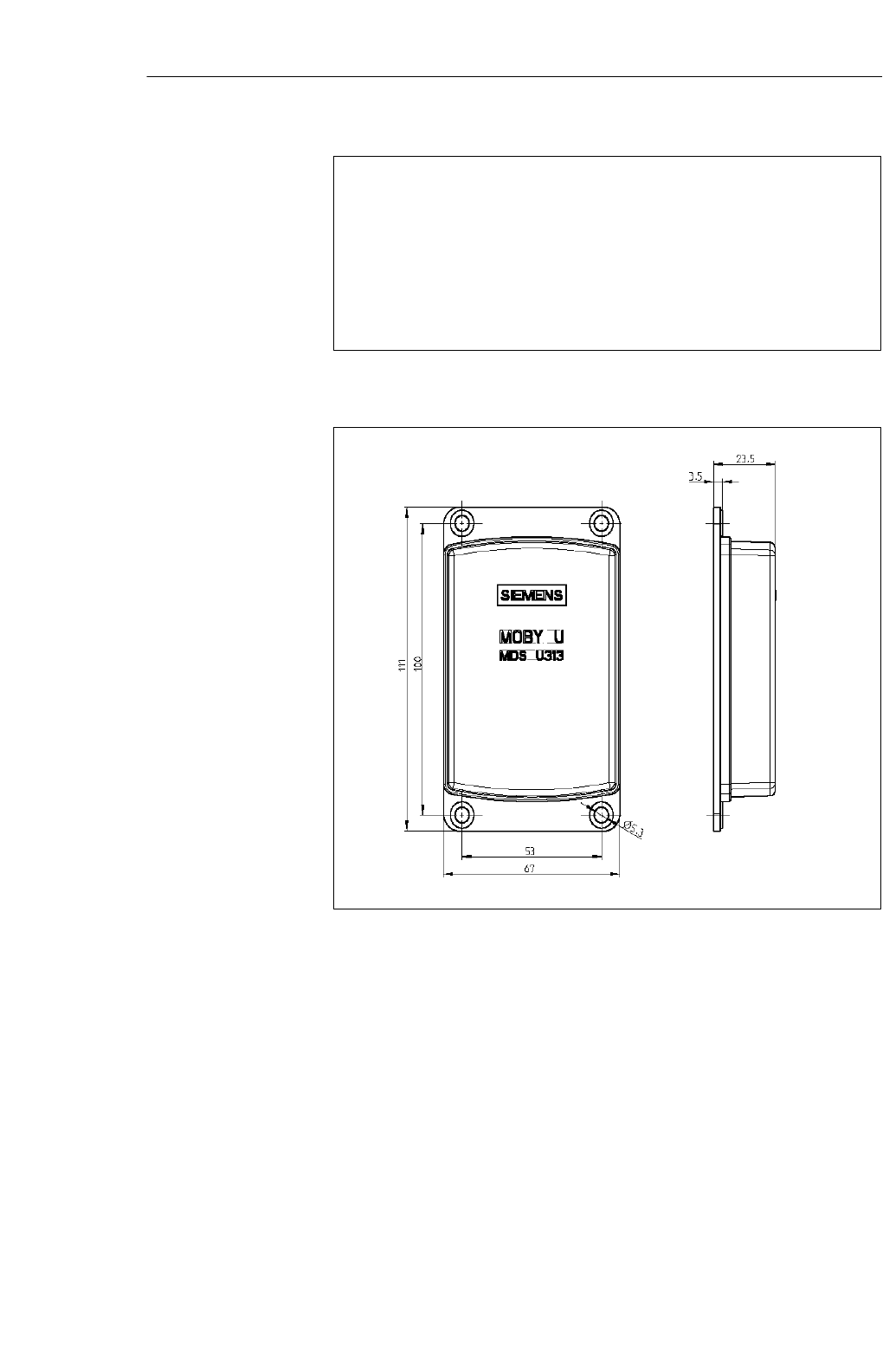
Housing
Dimensions (L x W x H) in mm
Color/material
111 x 67 x 23.5
Anthracite/plastic, PA 12 GF 25
Ambient temperature
Operation
Transportation and storage
–25 to +70 °C
–40 to +85 °C
Weight, approx. 100 g
1) Lifespan depends on temperature, time MDS is in the SLG’s antenna field (zones 1 and
2) and the amount of read/written data (see chapter LEERER MERKER).
Table 4-5 Field data of the MDS U313
Standard Minimal Maximal
Working distance (Sa) 1400 350
Limit distance (Sg) 2000 500
Transmission window (L) 2800 700
Transmission window (W) 2800 700
Minimum distance of MDS to MDS
with
Bunch > 1
Bunch = 1 Directly adjacent
The minimum distance must be such that only
one MDS can be inside the range limit.
The field data apply to reading and writing the MDS. Overranging can be
actively limited by the SLG (in increments of 0.5 m).
Field data (in mm)
Mobile Data Memorie
s
4-8 MOBY U – Manual for Configuration, Installation and Service
(4) J31069-D0139-U001-A2-7618
Representation of ”metal–free
space”
Figure 4-3 Metal–free space, MDS U313
Figure 4-4 Dimensions, MDS U313
Metal–free space
(in mm)
Dimensions (in
mm)
Mobile Data Memorie
s
4-9
MOBY U – Manual for Configuration, Installation and Service
(4) J31069-D0139-U001-A2-7618
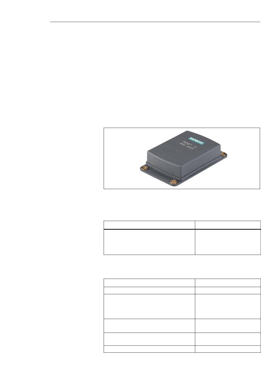
4.3 MDS U524
The MDS U524 is a mobile data memory (MDS) with a large, 32–Kbyte stor-
age capacity for use in the automotive industry and other industrial produc-
tion plants with similar requirements. The particularly low current consump-
tion guarantees a long life of 8 years. The interference–immune and robust
MDS can be read and written at a maximum distance of 3 m. Addressing the
MDS U524 is easy with the filehandler (from MOBY I) which uses logical
file addresses. In addition, the MDS can also be used with direct memory
accessing. The transmission frequency in the ISM frequency band at 2.4 GHz
makes the MDS’s net data transmission speed very fast (up to 16 Kbyte/sec
without multitaging and up to 8 Kbyte/sec with multitaging of two MDSs).
Figure 4-5 MDS U524
Table 4-6 Ordering data of the MDS 524
Order No.
Mobile data memory MDS U524
With 32–Kbyte RAM
MDS ID number (32 bits)
Read–only memory (128 bits)
6GT2500-5CE10
Table 4-7 Technical data of the MDS U524
Fixed code memory MDS ID number (32 bits)
Read–only memory 128 bits, to be written once by user
Application memory
Memory technology
Memory size
Memory organization
RAM
32 Kbytes
Byte access; filehandler mode
Data retention time 10 years
MTBF (at +40°C) 2.5 x 10⁶ hours (without conside-
ring battery)
Read/write distance 0.15 m up to 3 m
Ordering data
Technical data
Mobile Data Memorie
s
4-10 MOBY U – Manual for Configuration, Installation and Service
(4) J31069-D0139-U001-A2-7618
Table 4-7 Technical data of the MDS U524
Depends on direction No
Multitaging capability Yes
Power supply Battery
Battery lifespan w 8 years at +25°C 1;
No replacement
Shock, vibration in acc. w. DIN EN 721-3-7,
class 7 M3 50 g/10 g
Free fall 1 m
Mounting 4 M4screws
Tightening moment (at room temperature) v 0.8 Nm
Recommended distance from metal Can be mounted directly on metal
Protection rating in acc. w. EN 60529 IP 68
Chemical resistance See table 4-2.
Housing
Dimensions L x W x H (in mm)
Color
Material
111 x 67 x 23.5
Anthracite
Plastic, PA 12 GF 25
Ambient temperature
Operation
Transportation and storage
–25 to +85 °C
–40 to +85 °C
Weight, approx. 100 g
1 Lifespan depends on temperature, time MDS is in the SLG’s antenna field (zones 1 and
2) and the amount of read/written data (see chapter LEERER MERKER).
Table 4-8 Field data of the MDS U524
Standard Minimal Maximal
Working distance (Sa) 1400 350
Limit distance (Sg) 2000 500
Transmission window (L) 2800 700
Transmission window (W) 2800 700
Minimum distance of MDS to MDS
with
Bunch > 1
Bunch = 1
Directly adjacent
The minimum distance must be such that only
one MDS can be inside the range limit.
The field data apply to reading and writing the MDS. Overranging can be
actively limited by the SLG (in increments of 0.5 m).
Field data (in mm)
Mobile Data Memorie
s
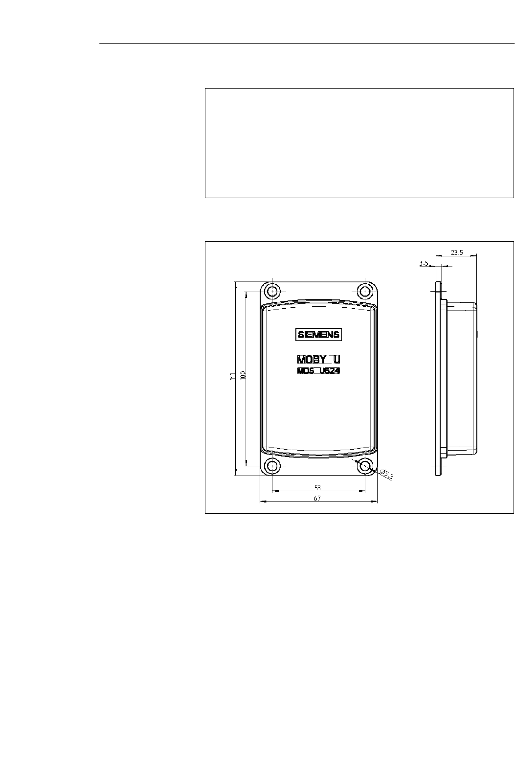
4-11
MOBY U – Manual for Configuration, Installation and Service
(4) J31069-D0139-U001-A2-7618
Representation of ”metal–free
space”
Figure 4-6 Metal–free space, MDS U524
Figure 4-7 Dimensions of MDS U524
Metal–free space
(in mm)
Dimensions (in
mm)
Mobile Data Memorie
s
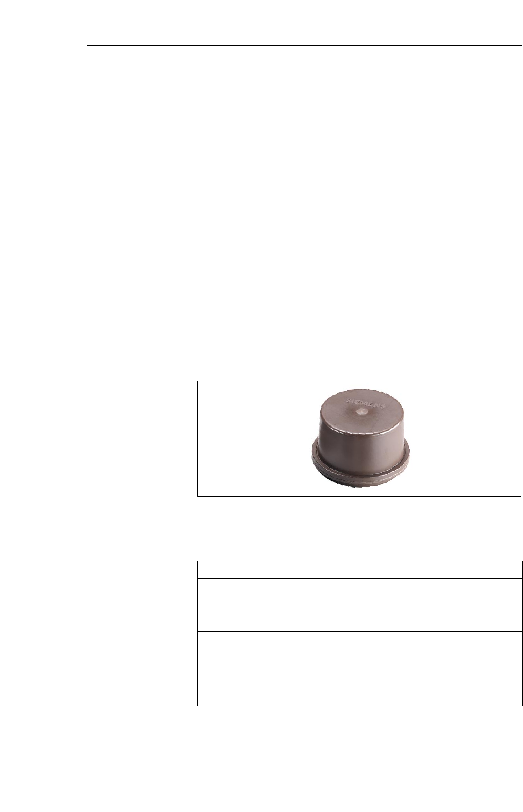
4-12 MOBY U – Manual for Configuration, Installation and Service
(4) J31069-D0139-U001-A2-7618
4.4 MDS U589
The MDS U589 is a mobile data memory (MDS) with a large, 32–Kbyte stor-
age capacity. It is designed for use at high temperature ranges (up to +220
°C, cyclically) especially in the paint shops of the automotive industry. The
size of the MDS permits it to be attached to a skid or directly to a chassis.
The particularly low current consumption guarantees a long life of 5 years.
The interference–immune and robust MDS can be read and written at a maxi-
mum distance of 3 m. Addressing the MDS U589 is easy with the filehandler
(from MOBY I) which uses logical file addresses. In addition, the MDS can
also be used with direct memory accessing. The transmission frequency in
the ISM frequency band at 2.4 GHz makes the MDS’s net data transmission
speed very fast (up to 16 Kbyte/sec without multitaging and up to 8 Kbyte/
sec with multitaging of two MDSs).
Some typical applications are listed below.
SBasic coat, KTL area, cataphoresis with drying chambers
SCovering coat
SWashing at temperatures > 85 °C
SOther applications with high temperatures
Figure 4-8 MDS U589
Table 4-9 Ordering data of the MDS U589
Order No.
Mobile data memory MDS U589
With 32–Kbyte RAM
MDS ID number (32 bits)
Read–only memory (128 bits)
6GT2 500-5JK10
Accessories:
Holder
Standard model for MDS U589
Short model for MDS 439E/U589
Long model for MDS 439E/U589
Covering hood for MDS 439E/U589
6GT2 590-0QA00
6GT2 090-0QA00
6GT2 090-0QA00-ZA31
6GT2 090-0QB00
Ordering data
Mobile Data Memorie
s

4-13
MOBY U – Manual for Configuration, Installation and Service
(4) J31069-D0139-U001-A2-7618
Table 4-10 Technical data of the MDS U589
Fixed code memory MDS ID number (32 bits)
Read–only memory 128 bits, to be written once by user
Application memory
Memory technology
Memory size
Memory organization
RAM
32 Kbytes
Byte access; filehandler mode
Data retention time 10 years
MTBF (at +40°C) 2.5 x 10⁶ hours (without conside-
ring battery)
Read/write distance 0.15 m up to 3 m
Depends on direction No
Multitaging capability Yes
Power supply Battery
Battery lifespan w 5 years at +25°C 1;
No replacement
Shock, vibration in acc. w. DIN EN 721-3-7,
class 7 M3 50 g/5 g 2
Free fall 1 m
Mounting With holder
Recommended distance from metal Can be mounted directly on metal
Protection rating in acc. w. EN 60529 IP 68
Chemical resistance See table 4-2.
Housing
Dimensions (Ø x H) in mm
Color/material
114 x 83
Brown/PPS
Ambient temperature
Operation
Transportation and storage
–25 to +220 °C (cyclic)
–40 to +85 °C
Weight, approx. 600 g
1 Lifespan depends on temperature, time MDS is in the SLG’s antenna field (zones 1 and
2) and the amount of read/written data (see chapter LEERER MERKER).
2 Only applies to original holder
Technical data
Mobile Data Memorie
s
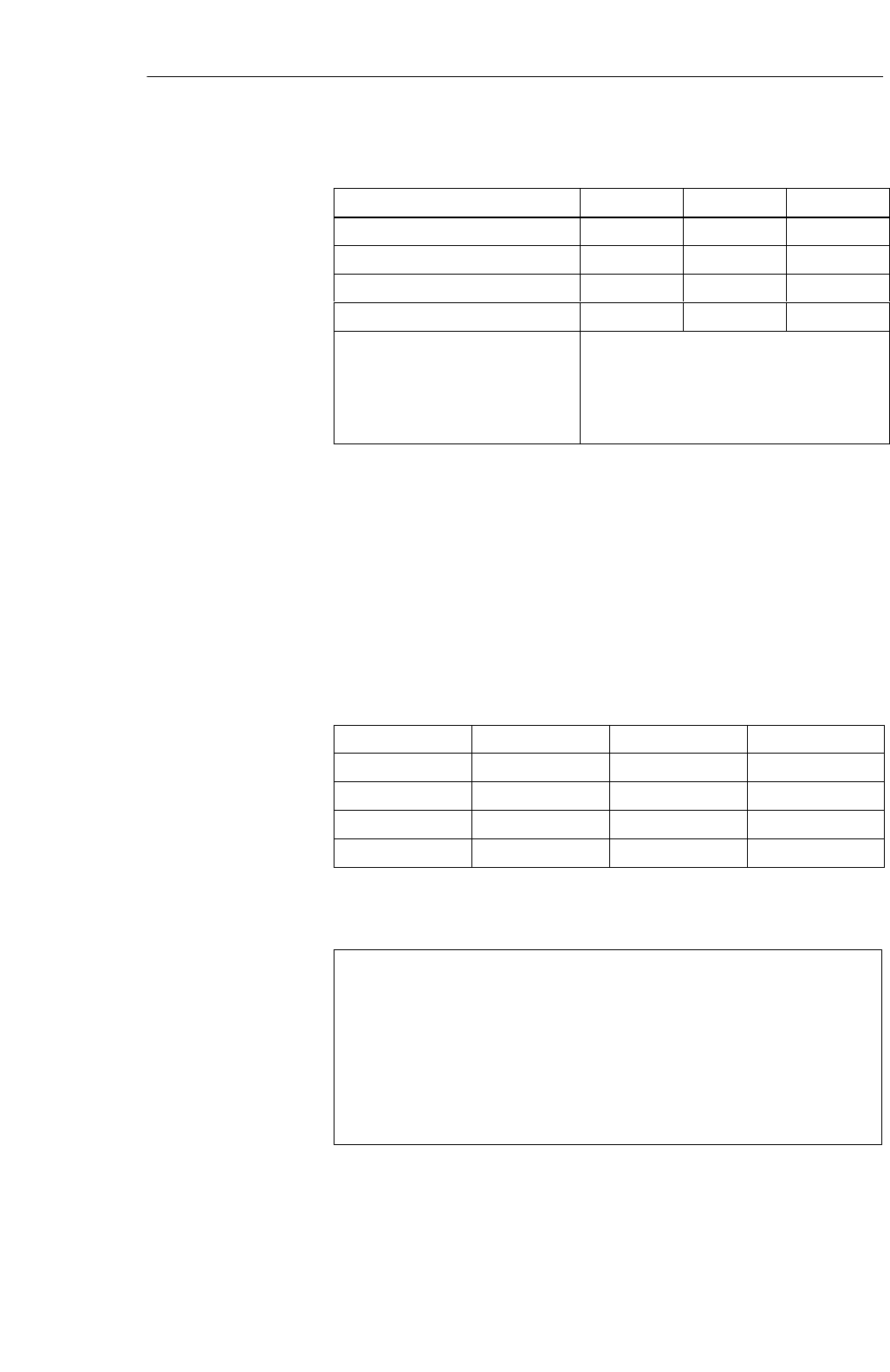
4-14 MOBY U – Manual for Configuration, Installation and Service
(4) J31069-D0139-U001-A2-7618
Table 4-11 Field data of the MDS U589
Standard Minimal Maximal
Working distance (La) 1400 350
Limit distance (Lg) 2000 500
Transmission window (L) 2800 700
Transmission window (W) 2800 700
Minimum distance of MDS to MDS
with
Bunch > 1
Bunch = 1
Directly adjacent
The minimum distance must be such that only
one MDS can be inside the range limit.
The field data apply to reading and writing the MDS. Overranging can be
actively limited by the SLG (in increments of 0.5 m).
At temperatures between 85 °C and 200 °C (briefly at 220 °C), the interior
temperature of the MDS must never be allowed to exceed the critical
threshold of 85 °C. Every heating up phase must be followed by a cooling off
phase. The following tables lists several cycles of the MDS U589 at its
utmost limits.
Table 4-12 Cycles of the MDS U589at its utmost limits
Tu (Heating Up) Heating Up Tu (Cooling Off) Cooling Off
200°C1 h 25 °C> ? h
25 °C> ? h
25 °C> ? h
25 °C> ? h
Siemens will calculate a temperature profile on request.
Representation of ”metal–free
space”
Figure 4-9 Metal–free space, MDS U589
Field data (in mm)
Cyclic operation of
MDS at
temperatures
> 85 5C
Metal–free space
(in mm)
Mobile Data Memorie
s
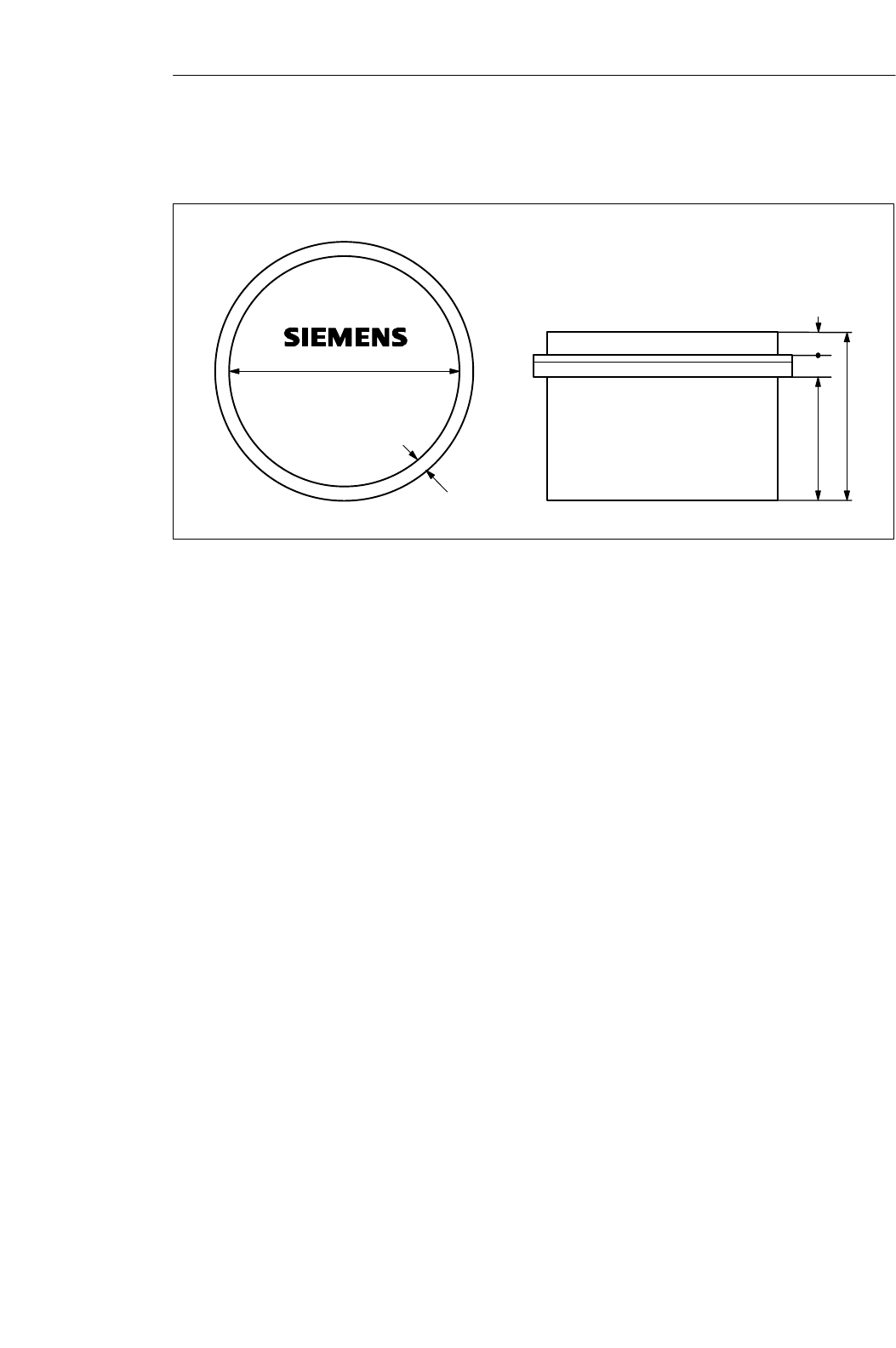
4-15
MOBY U – Manual for Configuration, Installation and Service
(4) J31069-D0139-U001-A2-7618
114"0.5
7.5"0.5
11"1
83"3
61"1
11"1
Figure 4-10 Dimensions of the MDS U589
Dimensions
(in mm)
Mobile Data Memorie
s

4-16 MOBY U – Manual for Configuration, Installation and Service
(4) J31069-D0139-U001-A2-7618
Mobile Data Memorie
s
5-1
MOBY U – Manual for Configuration, Installation and Service
(4) J31069-D0139-U001-A2-7618
Read/Write Devices 5

5-2 MOBY U – Manual for Configuration, Installation and Service
(4) J31069-D0139-U001-A2-7618
5.1 SLG U92
The MOBY U identification system was designed especially for applications
in automotive production, logistics and similar where high demands are
placed on interference immunity, long read/write distances with moving data
memories, quick and reliable data transmission, easy installation, and reliable
function even in rugged environments. It uses the ISM frequency band of 2.4
GHz (familiar world–wide). Its emission strength is way below the values
recommended by well–known health authorities from all over the world.
MOBY U covers a transmission range of up to three meters and thus pro-
vides the prerequisites for a transparent identification solution. The SLG is
available for every situation with 2 interface versions.
The primary application areas for MOBY U are listed below.
SMain assembly lines of the automotive industry (raw product manufactur-
ing, surface treatment and assembly)
SVehicle identification/entry check for moving companies, vehicle parks,
and so on
SContainer/pallet identification for transportation logistics and distribution
STraffic control technology
SAssembly lines
The SLG U92 handles the commands received from the interface or PC/PLC.
The commands with the data to be read or written are converted into
appropriate communication commands via the HF interface between SLG
and MDS. The amount of data that can be transferred between SLG and MDS
depends on the following factors.
SThe speed at which the MDS moves through the SLG’s transmission win-
dow
SThe length of the transmission window
SThe number of MDSs in the transmission window (bunch/multitag)
SThe time during which the MDS is ready for communication (depends on
sleep time and standby time)
The SLG U92 is available in two hardware versions for connection to differ-
ent systems.
SSystem interface with RS 232
for serial connection to any system
(PC/PLC/communications processors)
SSystem interface with RS 422
for serial connection to MOBY interfaces (ASM 475, ASM 473, ASM
452) for integration in SIMATIC S7 or PROFIBUS or any system (PC/
PLC/communications processors)
Application area
Setup and
functions
Read/Write Devices

5-3
MOBY U – Manual for Configuration, Installation and Service
(4) J31069-D0139-U001-A2-7618
Except for the system interface, the hardware and firmware of both hardware
versions are identical.
Software tools such as SIMATIC S7 functions (FC 45/FC 46)
and the MOBY API library for applications under Windows 98/NT/2000
make implementation in specific applications easy.
The integrated file management system (compatible with the familiar MOBY
I filehandler and supplemented with multitag commands) ensures simple,
convenient administration of data on the mobile data memories.
The SLG U92 works with a transmission frequency in the ISM band between
2.4 and 2.4835 GHz. This makes transmission distances of up to three meters
possible with a very low sending strength (less than 50 mV per meter at
3-m intervals) and high net transmission speeds of up to 16 Kbyte/sec. By
selection of the transmission frequency, use of robust modulation procedures
and appropriate check routines, sources of electromagnetic interference can
be disregarded and you are still assured of correct data transmission and in-
tegrity. MOBY U technology eliminates familiar interference during UHF
transmissions such as reflection, interference and overranging. Specially de-
signed antennas ensure a homogenous transmission field in which mobile
data memories (MDSs) are always (100%) detected. This means expensive
shielding and antenna directing can be omitted. The antenna field of the SLG
can be activated and deactivated for communication with an MDS with a
function call or automatically by triggering a digital input. There are two
ways to manage the data on the mobile data memory.
SByte addressing via absolute addresses (start address, length)
SConveniently with a file management system (compatible with the
MOBY I filehandler)
When the filehandler is used, the MOBY U read/write device always fetches
its file management information directly from the MDS.
The SLG U92 can be run at three levels.
1. MOBY U can be used for existing system solutions with MOBY I with
standard settings, unchanged filehandler functions but without the MOVE
and LOAD commands which used to be required.
2. Only a few extra commands are required for changes in the standard
settings and requesting diagnostic data.
3. Utilization of all features including multitaging. At this level, the
commands and/or user data can also be clearly related to the MDS
number.
Two LEDs show the current status (e.g., communication) and make commis-
sioning easier.
Read/Write Devices
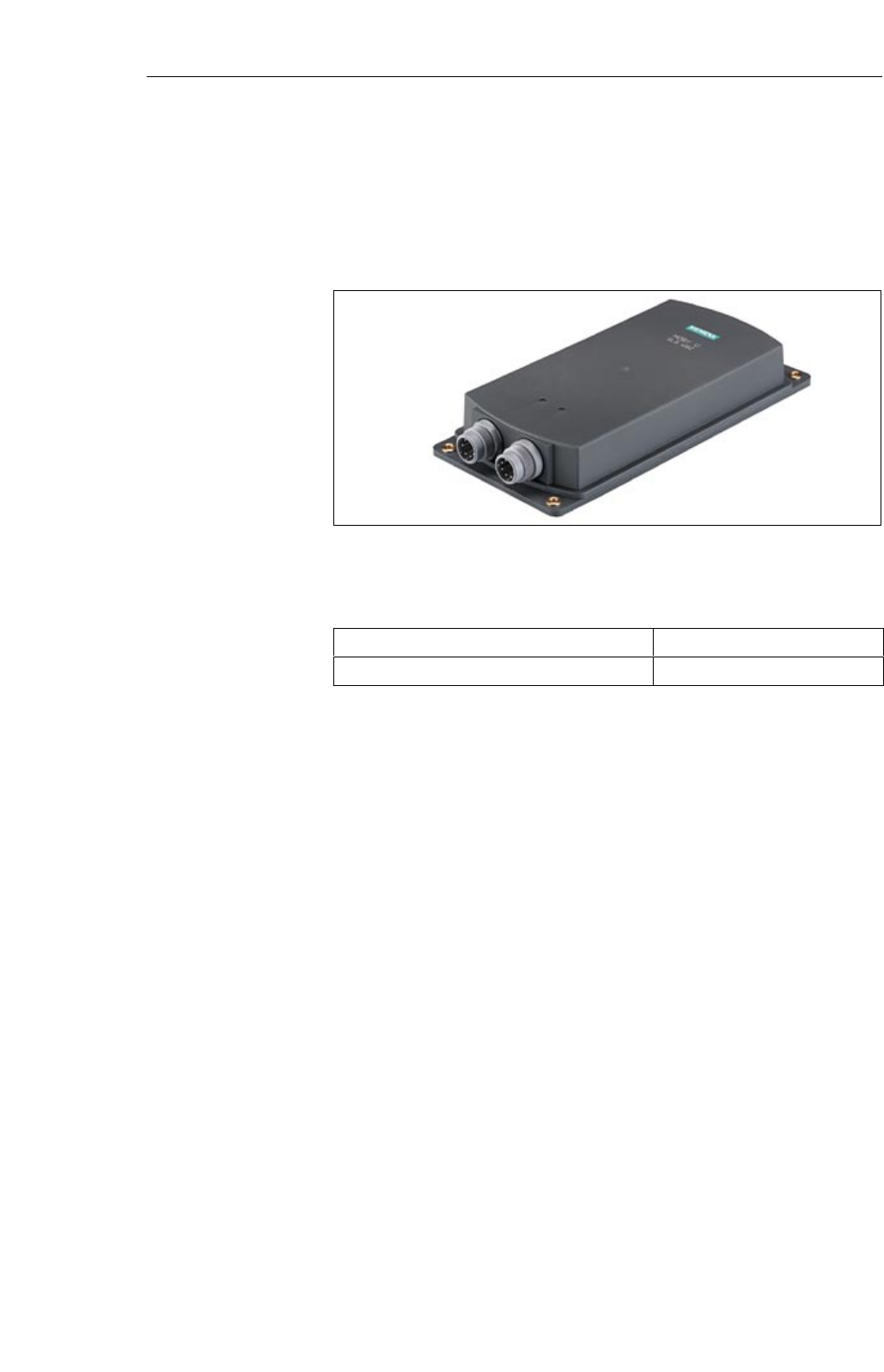
5-4 MOBY U – Manual for Configuration, Installation and Service
(4) J31069-D0139-U001-A2-7618
A separate service and diagnostic interface (RS 232) is available for easy
commissioning and diagnosis later during regular operation. In addition, the
service function ”load software to SLG” can be used to load future function
expansions via this interface without having to exchange the SLG in existing
applications.
Figure 5-1 Read/write device SLG U92
Table 5-1 Ordering data of the SLG U92
SLG U92 read/write device with RS 422 6GT2501-0CA00
SLG U92 read/write device with RS 232 6GT2501-1CA00
Ordering data
Read/Write Devices

5-5
MOBY U – Manual for Configuration, Installation and Service
(4) J31069-D0139-U001-A2-7618
Table 5-2 Technical data of the SLG U92
Air interface
Transmission frequency 2.4 to 2.4835 GHz
Band width 2 x 1 MHz within 83 MHz
Gross bit rate of radio channel 384 kbit/sec
Data transmission speed (net) Without bunch With bunch size of 2
p()
Write
Read Approx. 16.0 Kbyte/sec
Approx. 14.4 Kbyte/sec Approx. 8.0 Kbyte/s
Approx. 7.2 Kbyte/sec
Range (read/write) 0.15 m up to 3 m
Limit distance (Lg)
Maximal
Adjustable via range limitation
3.0 m
Maximal
Minimal
Default
3
.
0
m
0.5 m
1.5 m
Location resolution Range limitation, adjustable in 0.5 m increments
Working distance (La)Approx. 75% of limit distance Lg
Field length/width at Lg = 1.5 m 2 m
Read/write device (SLG)
Functions MOBY filehandler
Direct read/write access
Multi-identification capability Up to 12 MDSs
MDS recording time < 1 sec for 12 MDSs
Object speed < 2 m/sec at La = 1.5 m and < 2.5 Kbytes of data
read/written
Power supply 24 V DC (nominal value), 20 V DC to 30 V DC
Limited Power Source according EN 60 950 /
IEC 60 950
Current consumption (send) < 300 mA
Operating modes (SLG) Standby
Search
Communication
Synchronization, SLG - SLG By semaphore control with 2nd interface; max. of
3 SLGs together
Minimum distance between two
SLGs > 6 m
Directly adjacent with synchronization
SLG - SLG
Technical data
Read/Write Devices
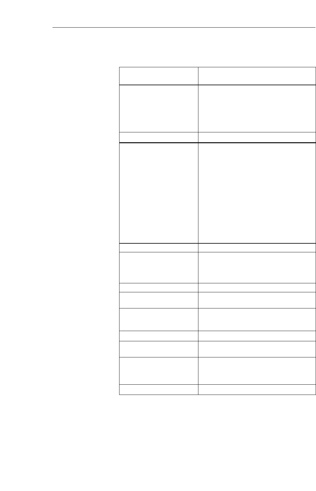
5-6 MOBY U – Manual for Configuration, Installation and Service
(4) J31069-D0139-U001-A2-7618
Table 5-2 Technical data of the SLG U92
ASM/PC Interface 6–pin SLG plug in acc. w. EN 175201-804
RS 232 or RS 422 (SLG U92 version)
Transmission speed
Transmission protocol
Line length, SLG - ASM
Line length, SLG - PC
Automatic baud rate recognition, 19.2 to 115.2
KBaud (depends on ASM/PC and/or line length)
3964 R
Max. of 1000 m (RS 422; shielded)
Max. of 30 m (RS 232; shielded)
Service interface 11-pin plug in acc. w. EN 175201-804
Interface for service
Transmission speed
Line length, SLG - PC
Transmission protocol
2 DIs for proximity switch
DI 1/DI 2
DI 1 (or DI 2)
Line length, SLG - proximity
switch
Interface for SLG synchroniza-
tion
Line length, SLG - SLG
RS 232
19.2 KBaud
Max. of 30 m
Terminal, ASCII characters
Proximity switch for trigger antenna field, on/off
Proximity switch for antenna field duration, on
Max. of 50 m
Max. of 30 m
Indicator elements 2 LEDs
Housing
Dimensions [L x W x H]
Color
Material
290 x 135 x 42 without plug
Anthracite
Plastic, PA 12 GF 25
Mounting 4 M6screws
Tightening moment (at room
temperature)
v 2 Nm
Shock, vibration in acc. w. DIN
EN
721-3-7, class 7 M3
30 g/1.5 g
MTBF (at +40 °C) 2 x 10⁶ hours
Protection rating in acc. w. EN
60529 IP 65
Ambient temperature
Operation
Transportation and storage
–25 to +70 °C
–40 to +85 °C
Weight, approx. 900 g
Read/Write Devices
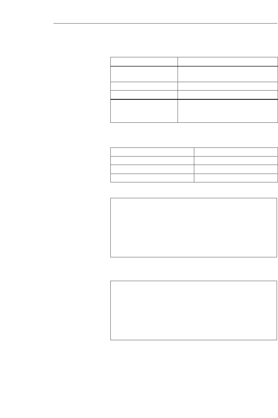
5-7
MOBY U – Manual for Configuration, Installation and Service
(4) J31069-D0139-U001-A2-7618
Table 5-2 Technical data of the SLG U92
Antenna Integrated in the SLG
Emission
Emission density
< 50 mV per meter at 3-m intervals
< 0.5 mW/cm2 (at distance of 1 m)
Angle of opening Approx. 90 ° horizontal/vertical
Polarization Circular
Certifications BAPT (ETS 300 440), FCC (15.249)
CE (ETS 300 683), UL, CSA
Safe for pacemakers
The field data are the same regardless of MDS type.
Table 5-3 Technical data of the SLG U92
Working distance (La)150 to
Limit distance (Lg)
Transmission window L
Minimum distance D from SLG to SLG
Presentation of ”transmission win-
dow”
Figure 5-2 Transmission window of the SLG U92
Representation of ”metal–free
space”
Figure 5-3 Metal–free space of SLG U92
Field data
Transmission
window
Metal–free space
(in mm)
Read/Write Devices
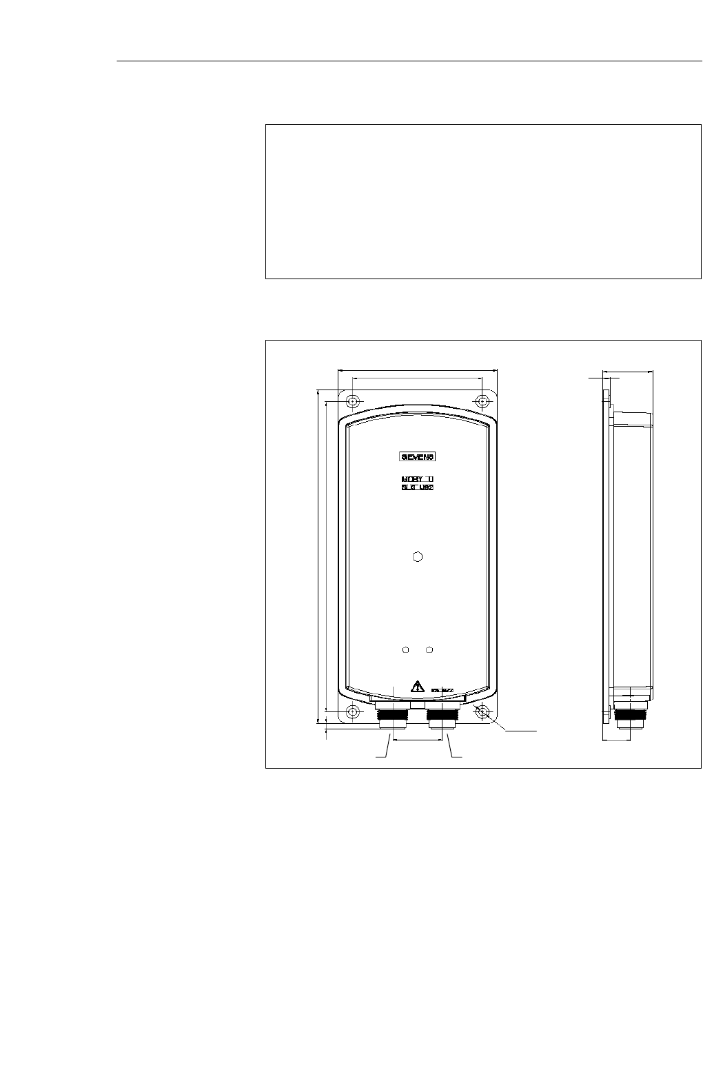
5-8 MOBY U – Manual for Configuration, Installation and Service
(4) J31069-D0139-U001-A2-7618
Presentation of ”definition of distance D”
Figure 5-4 Distance D: SLG U92
Service interface To ASM/PC
135 110 42
6
23.2
290
4.7 270
42 ∅6.5
Figure 5-5 Dimensional drawing of the SLG U92
Definition distance
D
Dimensions (in
mm)
Read/Write Devices
6-1
MOBY U – Manual for Configuration, Installation and Service
(4) J31069-D0139-U001-A2-7618
Interfaces 6

6-2 MOBY U – Manual for Configuration, Installation and Service
(4) J31069-D0139-U001-A2-7618
6.1 Introduction
The ASM interfaces are the link between the MOBY U components
(SLGs/MDSs) and the high–level controllers (e.g., SIMATIC S7) or PCs or
computers. Depending on the interface used, up to two SLGs can be
connected.
An ASM consists of a microcontroller system with its own program (PROM).
The CPU receives the commands over the user interface and stores these in
the RAM. The user receives an acknowledgment that the command has
arrived. If the command is okay, the CPU begins executing it.
Table 6-1 Overview of the interfaces
ASM
Type Interfaces
to PC/
Computer
Interfaces
to SLG Function
Blocks SLG
Connec-
tions
Dimensions
(W x H x D in
mm)
Temperature
Range
(Operation)
Protect
ion
Rating
ASM 452 PROFIBUS-
DPV1 2 x 5–pin
prox. switch
plug
FC 45
FC 46
FC 56
1134 x 110 x 55 0 to +55 °CIP 67
ASM 473 Can be plug-
ged into
ET 200X
2 x 5–pin
prox. switch
plug
FC 45
FC 56 187 x 110 x 55 0 to +55 °CIP 67
ASM 475 Can be plug-
ged into
S7-300/
ET 200M
Via screw
terminals FC 45
FC 56 2
(parallel) 40 x 125 x 120 0 to +60 °CIP 20
Application area
Setup and
functions
Overview
Interfaces
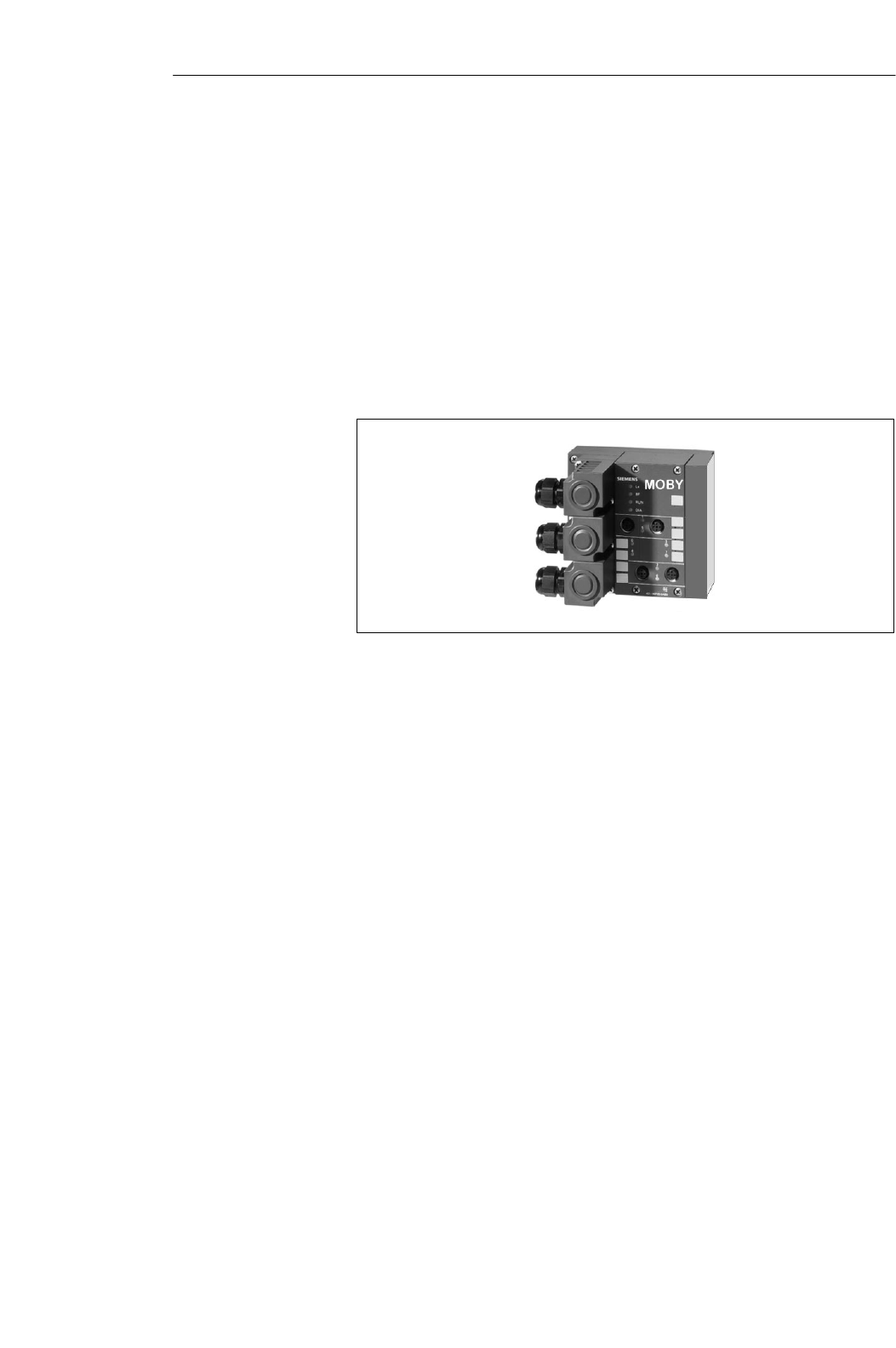
6-3
MOBY U – Manual for Configuration, Installation and Service
(4) J31069-D0139-U001-A2-7618
6.2 ASM 452
The ASM 452 interface is a MOBY module for use with MOBY components
via PROFIBUS–DPV1 on the following devices.
SAll computers and PCs
SAll controllers
When the interfaces are used with a SIMATIC S7, function blocks are avail-
able to the user.
Figure 6-1 Interface ASM 452
The ASM 452 represents the further development of the familiar 450/451
interface modules. By using non–cyclic data communication on PROFIBUS–
DPV1, even the most extensive PROFIBUS configurations have optimum
data throughput. The minimum cyclic data load of the ASM 452 on PROFI-
BUS guarantees the user that other PROFIBUS stations (e.g., DI/DO) will
continue to be processed very quickly.
The ASM 452 is an interface module for communication between PROFI-
BUS and the SLG U92 with RS 422. The data on the MDS U313/524/589can
be addressed with the ASM 452 in the following ways.
S Physical addressing (”normal” addressing) or
S With a filehandler similar to DOS
The SIMATIC S7 offers FCs for the two methods of access.
SFC 45 for ”normal” addressing
SFC 46 for filehandler without multitaging. FC 56 for filehandler with
multitaging.
FC 45 and FC 46/56 give the S7 user an easy–to–use interface with powerful
commands. FC 45 and FC 56 offer additional command chaining and S7 data
structures via UDTs.
Application area
Interfaces

6-4 MOBY U – Manual for Configuration, Installation and Service
(4) J31069-D0139-U001-A2-7618
Table 6-2 Ordering data of the ASM 452
Interface ASM 452
for PROFIBUS-DPV1
can be connected with 1x SLG U92 with
RS 422
6GT2 002-0EB20
Accessories:
Plug connector for PROFIBUS–DP connec-
tion and 24 V power
SLG cable ASM 452 $ SLG
Length 2 m; standard cable
Other lengths: 5 m, 10 m, 20 m and 50 m
Opt. conn. plug without SLG cable
(for cable lengths > 20 m)
ASM 452 $ SLG
M12 covering caps for unused SLG connec-
tions (1 package = 10 each)
MOBY software 1)
with FC 46, FC 45, FC 56, GSD file
6ES7 194-1AA00-0XA0
6GT2 091-1CH20
6GT2 091-1C...
6GT2 090-0BC00
3RX9 802-0AA00
6GT2 080-2AA10
Replacement part:
Plug connector plate; T design for PROFI-
BUS connection 6ES7 194-1FC00-0XA0
Description of FC 45 (for ASM 452)
deutsch
English 6GT2 097-3AM00-0DA1
6GT2 097-3AM00-0DA2
Description of FC 46 (for ASM 452)
deutsch
English 6GT2 097-3AC40-0DA1
6GT2 097-3AC40-0DA2
Description of FC 56
1) See chapter .7.1
Ordering data
Interfaces
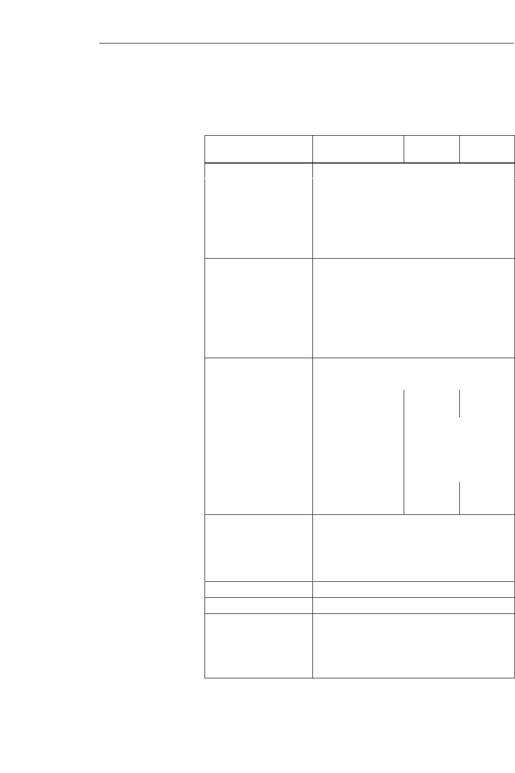
6-5
MOBY U – Manual for Configuration, Installation and Service
(4) J31069-D0139-U001-A2-7618
Table 6-3 Technical data of ASM 452
ASM 452
with FC 45 ASM 452
with FC 46 ASM 452
with FC 56
Serial interface to user PROFIBUS-DPV1
Procedure after connection EN 50170, vol. 2, PROFIBUS
PG 11 screw connection
PROFIBUS and power supply plugs are not included
Transmission speed
PROFIBUS
an
d
power supp
l
y p
l
ugs are not
i
nc
l
u
d
e
d
.
9600 Baud to 12 Mbaud (automatic detection)
Max. block length 2 words (cyclic)/240 bytes (non–cyclic)
Serial interface to SLG
Plug connector
Line length, max.
2 M12 coupling plugs
2 m = standard length;
Other prefabricated cables: 5 m, 10 m, 20 m,
50 ( t 1000 t)
50 m (up to 1000 m on request)
SLGs which can be connec-
ted 1x SLG U92 with RS 422
Software functions
Programming Depends on PROFIBUS-DP master
Function blocks for
SIMATIC S7 FC 45 FC 46 FC 56
MDS addressing Direct access with ad-
dresses Access via logical file names
(file system similar to DOS)
Commands Initialize MDS, read
data from MDS, write
data to MDS, and so on
Format MDS, read file, write
file, and so on
Multitag capability No No Yes
S7 data structures via UDTs Yes No Yes
Voltage
Nominal value
Permissible range
Current consumption
24 V DC
20 to 30 VDC
Max. of 180 mA; typ. 130 mA
(without SLG, DO not loaded)
Digital inputs None
Digital outputs None
Ambient temperature
Operation
Transportation and storage 0 to +55 °C
–40 to +70 °C
Dimensions (W x H x D) in
mm 134 x 110 x 55 (without bus plug)
Technical data
Interfaces
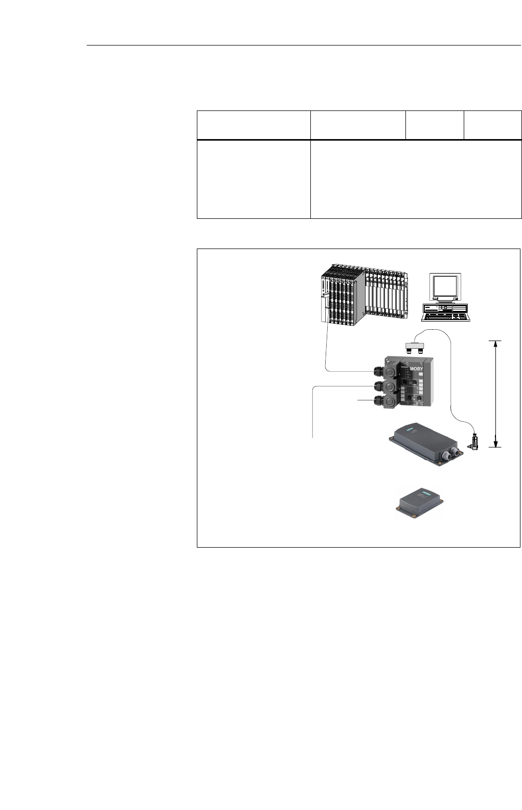
6-6 MOBY U – Manual for Configuration, Installation and Service
(4) J31069-D0139-U001-A2-7618
Table 6-3 Technical data of ASM 452
ASM 452
with FC 56
ASM 452
with FC 46
ASM 452
with FC 45
Mounting 4 M5 screws;
Mounting on all plates or walls
Weight, approx. 0.5 kg
Protection rating IP 67
MTBF (at 40 °C)30 x 104 hours = 34 years
PROFIBUS-DP
master module
(e.g., S7-400 CPU)
PROFIBUS line
To other
PROFIBUS stations
AT-comp. PC
24 V
for
SLG
SLG
* Standard cable lengths
2 m*
MDS
Figure 6-2 Configurator – ASM 452
The ASM 452 has the same housing as the distributed I/O device ET 200X.
For the general chapters on the ASM 452 (e.g., mounting, operation and
wiring, general technical data) see the ET 200X manual (order no. 6ES7
198-8FA00-8AA0). Accessories and network components are also covered by
this manual.
The ASM 452 is integrated in the hardware configuration with a GSD file.
The ASM is then configured with HW Config of SIMATIC Manager or
another PROFIBUS tool. ”MOBY software” contains a GSD file for the
ASM 452.
Hardware
description
PROFIBUS
configuration
Interfaces
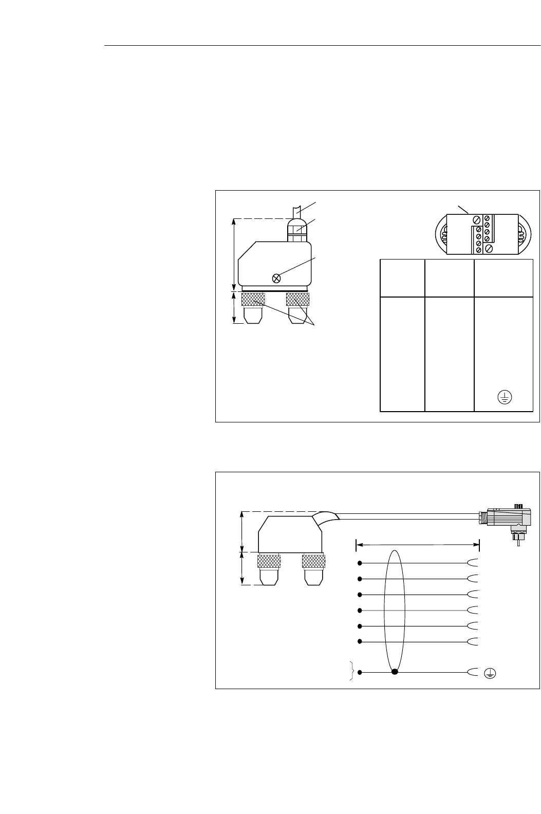
6-7
MOBY U – Manual for Configuration, Installation and Service
(4) J31069-D0139-U001-A2-7618
An SLG always occupies two M12 connection sockets on the ASM 452. A
prefabricated cable (cf. figure 6-4) makes it very easy to connect the SLG.
The standard version of the connection cable has a length of 2 m. Other
available lengths are 5 m, 10 m, 20 m and 50 m.
An SLG connection plug with screw terminals is available for users who
want to make their own cables (see figure 6-3). Cables and SLG connection
plugs can be ordered from the MOBY catalog.
SLG cable: 6GT2 090-0Ajjj
PG 11 screw;
Max. cable diameter = 6.5 mm
(Don’t tighten screw until plug is
assembled.)
2 screws to
open the plug
Coupling plug M12
on ASM 452
1
2
3
4
5
6
S
S
Plug Pin
1
2
3
4
5
6
S
S
Core
Color
Green
White
Brown
Yellow
Gray
Pink
- (nc)
Shield
Connection to
Pin of SLG
Plug
4
6
1
5
3
2
-
Plug covering hood removed
Protection rating IP 67
48
18.5
Figure 6-3 Connection plug for ASM 452, 473 $ SLG U92 with RS 422
(6GT2 090-0BC00)
6
1
4
5
3
2
Two 5–pin, round M12
plug connectors
X1/2
X1/3
X1/1
X1/4
X2/3
X2/1
X1/5
X2/5
x1 X2
White
Brown
Green
Yellow
Gray
Pink
SLG plug (socket)
2 m *
22.5
18.5
* Standard length
Figure 6-4 Connection cable for ASM 452, 473 $ SLG U92 with RS 422
(6GT2 091-1CH20)
SLG connection
technology
Interfaces
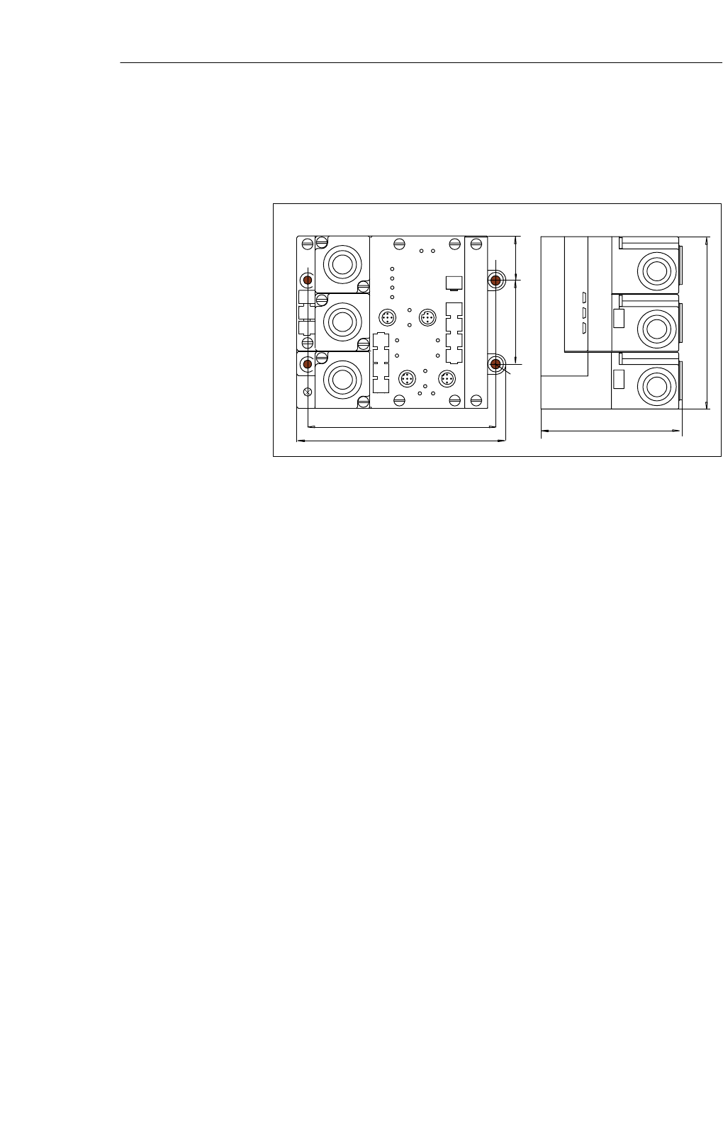
6-8 MOBY U – Manual for Configuration, Installation and Service
(4) J31069-D0139-U001-A2-7618
The following diagram shows a dimensional drawing of the ASM 452 with
bus connection plugs. The length of the PG screws and the radius of the cable
must both be added to the total width and depth specified below.
110
90
53.5 28.25
134
120
Ø 5.5
Figure 6-5 Dimensional drawing of the ASM 452
Dimensional
drawing
Interfaces
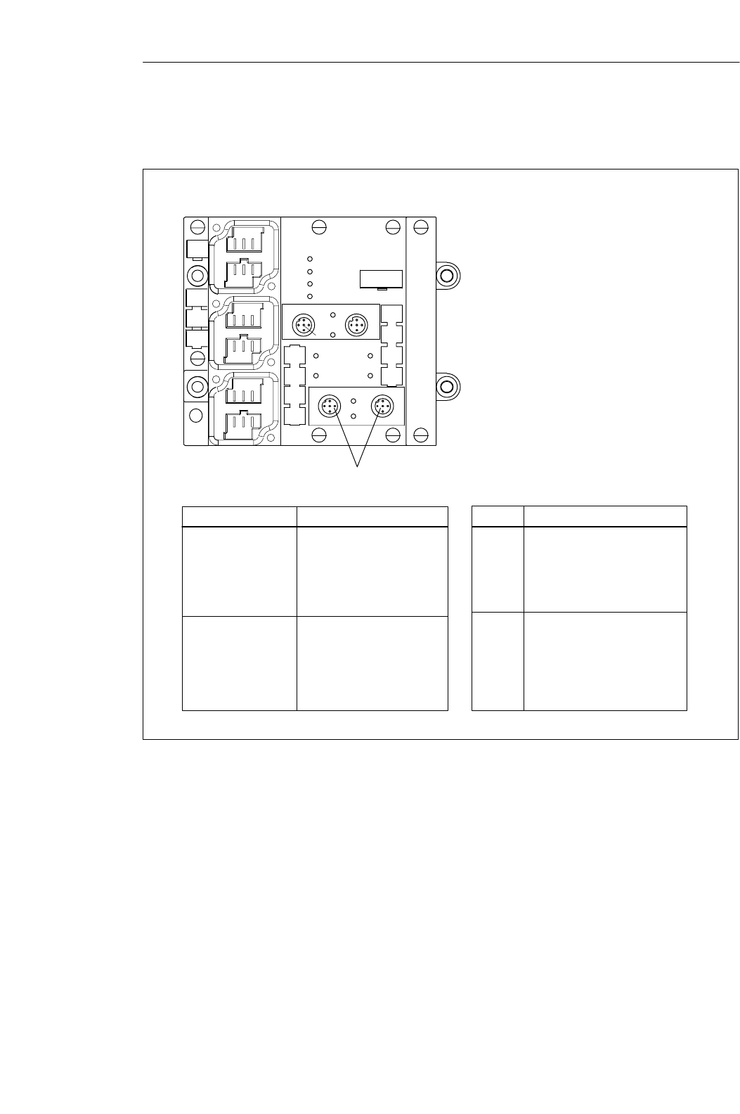
6-9
MOBY U – Manual for Configuration, Installation and Service
(4) J31069-D0139-U001-A2-7618
The figure below shows the pin allocations of the ASM 452.
1 +RxD
2 +TxD
3 -TxD
4 -RxD
5PE
1 +24 V
2 Res.
30 V
4 Res.
5PE
1
2
3
45
654
32
1
x1 X2
x3 x4
654
654
32
1
32
1
X11
X12
X13
Socket
X11 and X12
(PROFIBUS-DP)
Pin Allocation
1 Signal B
2PE
3* PE
4 Signal A
5* L+
6* M
X13
(power supply) 1PE
2L+
3M
4PE
5L+
6M
SF
BF
ON
24 V DC
LEDs for MOBY
RxD: Communication with SLG active
ANW: MDS present
ERR: Error indicator
All other LEDs are not assigned.
LEDs for PROFIBUS-DP
SF: System Fault (hardware error on ASM)
BF: Bus Fault (fault on PROFIBUS-DP)
ON: On when the logic voltage is present on
the ASM 452 (is generated from 24 V
power)
24 V DC: On when 24 V is connected to
ASM 452
* Don’t circuit
Pin Allocation (SLG)
Socket
X1/X3
RxD
ERR ANW
DE0 DE1
SLG2
RxD
X2
SLG1
Not available for MOBY U
Figure 6-6 Pin allocation and LEDs of the ASM 452
Pin allocations
Interfaces
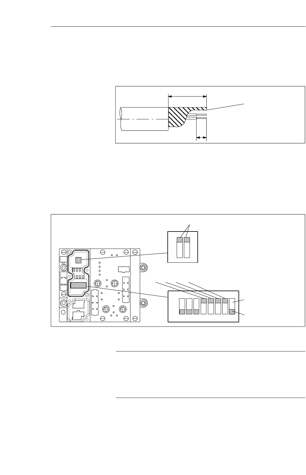
6-10 MOBY U – Manual for Configuration, Installation and Service
(4) J31069-D0139-U001-A2-7618
The following figure shows an example of how to bare a cable. The lengths
apply to all cables which you can connect to the connection plugs. Twist
existing shield braiding, stick in a core sleeve, and trim off excess.
45
6
Twisted and trimmed
shield braiding
Figure 6-7 Length of bared cable for PROFIBUS cable
The plug connector plate of the ASM must be removed before you can set the
PROFIBUS address or turn on the terminating resistance. The plug connector
plate covers the DIP switches. The following figure shows the location of the
DIP switches on the ASM and the applicable sample setting.
Example: PROFIBUS address 120 (status on delivery)
7654321
ON
23 +24 + 25 + 26 = 8 + 16 + 32 + 64 = 120
8
Example: Terminating resistance on (status on delivery)
OFF
ON
Res.
Filehandler
Figure 6-8 Setting PROFIBUS address/turning on terminating resistance
Note
SThe PROFIBUS address on the ASM 452 must always be the same as the
PROFIBUS address specified for this ASM in the configuration software.
SYou must always turn both DIP switches to ”on” or to ”off” so that the
terminating resistance is correct.
Example of how
much cable to bare
PROFIBUS
address and
terminating
resistance
Interfaces
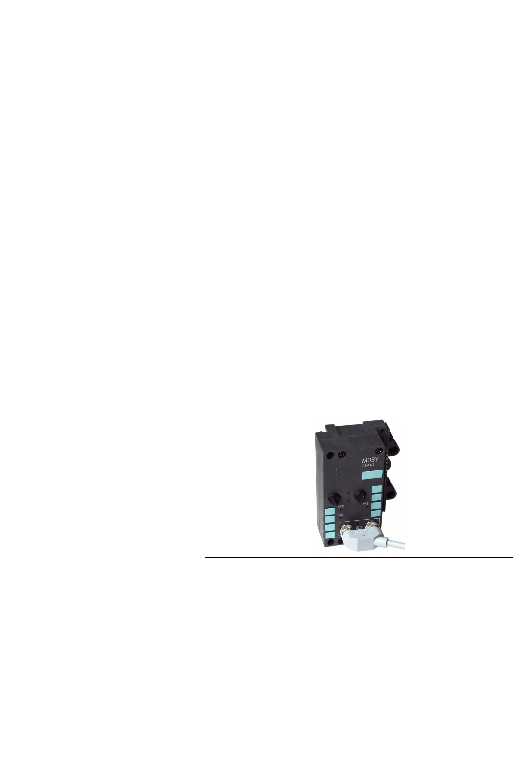
6-11
MOBY U – Manual for Configuration, Installation and Service
(4) J31069-D0139-U001-A2-7618
6.3 ASM 473
The ASM 473 interface is a MOBY module for the SIMATIC S7. It can be
connected to the distributed I/O device ET 200X and DESINA.
PROFIBUS–DPV1 serves as the interface to the user when the ET 200X is
used. An S7–300 or S7–400 with integrated PROFIBUS connection can be
used as the controller.
The ASM 473 supplements the SIMATIC S7 MOBY interface module ASM
475. With its protection rating of IP 67, it can be set up and operated directly
within the process without an extra protective case.
An ET 200X basic module (BM 141/142) with the order number
6ES7 141-1BF11-0XB0 or 6ES7 142-1BD21-0XB0 or a BM 143 is a prereq-
uisite for using the ASM 473.
The data are accessed on the MDS with physical addresses.
Function FC 45 is available for operation on a SIMATIC S7. The hardware
configuration of the ASM 473 is performed with an Object Manager (OM)
which is integrated in SIMATIC Manager.
Other features
SUp to 7 ASM 473s can be run in parallel on one ET 200X station.
SAll I/O modules from the ET 200X family can be run parallel to the ASM
473.
Figure 6-9 Interface ASM 473
Application area
Interfaces
6-12 MOBY U – Manual for Configuration, Installation and Service
(4) J31069-D0139-U001-A2-7618
Table 6-4 Ordering data of the ASM 473
Interface ASM 473
1x SLG U92 with RS 422 can be connected 6GT2 002-0HA00
Accessories:
SLG cable, ASM 473 $ SLG
Length 2 m; standard cable
Other lengths: 5 m, 10 m, 20 m and 50 m
Opt. conn. plug without SLG cable (for cable
lengths > 20 m)
ASM 473 $ SLG
MOBY Software1
with FC 45, GSD file
6GT2 091-1CH20
6GT2 091-1C...
6GT2 090-0BC00
6GT2 080-2AA10
Description of FC 45 (for ASM 473)
deutsch
English
6GT2 097-3AM00-0DA1
6GT2 097-3AM00-0DA2
1 See chapter 7.1.
Table 6-5 Technical data of the ASM 473
Interface to the ET 200X
Communication
Command buffer on ASM
SIMATIC S7 P bus,
cyclic/non–cyclic services
2 words (cyclic)/
238 bytes (non–cyclic)
142 x 238 bytes
Serial interface to SLG
Plug connector
Line length, max.
SLGs which can be connected
2 M12 coupling plugs
2 m = standard length;
Other prefabricated cables = 5 m,
10 m, 20 m, 50 m
(up to 1000 m on request)
1x SLG U92 with RS 422
Software functions
Programming
Function blocks for SIMATIC S7
MDS addressing
Commands
PROFIBUS diagnosis
S7 diagnosis
Firmware can be loaded.
Depends on PROFIBUS-DP ma-
ster
FC 45
Direct access with addresses
Initialize MDS, read data from
MDS, write data to MDS, and so
on
Yes, in acc. w. ET 200X basis sta-
tion
Yes, can be called via S7 OEM
Yes, via S7 OEM
Ordering data
Technical data
Interfaces
6-13
MOBY U – Manual for Configuration, Installation and Service
(4) J31069-D0139-U001-A2-7618
Table 6-5 Technical data of the ASM 473
Voltage
Nominal value
Permissible range
Current consumption
Power loss of the module
24 V DC
20.4 V to 28.8 V DC
Typ. 75 mA; max. of 500 mA (or
see technical data of your SLG)
1.6 W (typical)
Digital inputs/outputs Via expansion modules from the
ET 200X family
Ambient temperature
Operation
Transportation and storage
0 °C to +55 °C
–40 °C to +70 °C
Dimensions (W x H x D) in mm
Single device
Scaling interval
Mounting
Protection rating
Weight, approx.
87 x 110 x 55
60 x 110 x 55
2 M5 screws (supplied by custo-
mer)
2 M3 screws (supplied by device)
IP 67
0.275 kg
For information on setup and other general technical data, see the ET 200X
manual (order number 6SE7 198-8FA01-8AA0).
Interfaces
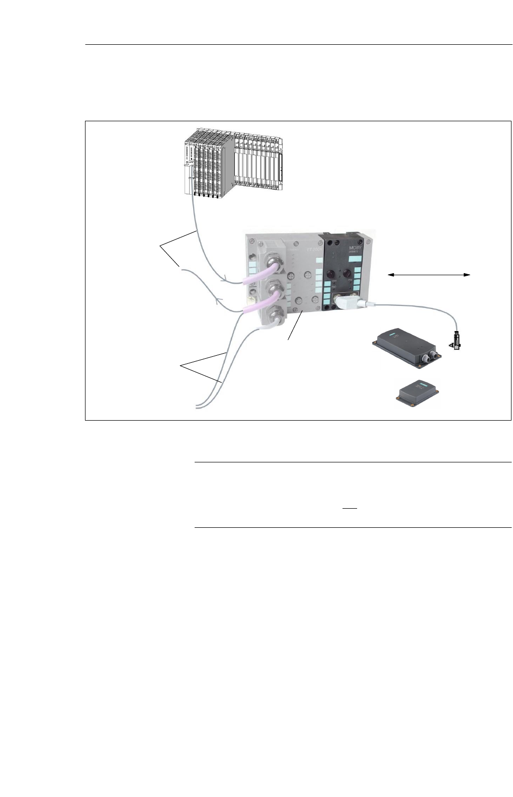
6-14 MOBY U – Manual for Configuration, Installation and Service
(4) J31069-D0139-U001-A2-7618
PROFIBUS-DP master module
(e.e., S7-400 CPU)
(Connection of master of other mfg
being prepared)
2 m (standard cable length)
MDS
PROFIBUS
to all
PROFIBUS slaves
24 V power for ET
200X electronics and
MOBY SLG
SLG
Basis module:
ET 200X; BM 141
ET 200X; BM 142
DESINA; BM 143
Figure 6-10 Configurator for an ASM 473
Note
The ET 200X differs from the ASM 452 (see figure 6-2) in that the 24 V
must be fed to the PROFIBUS plug and the load voltage plug (see ET 200X
manual for more information).
Configuration
Interfaces
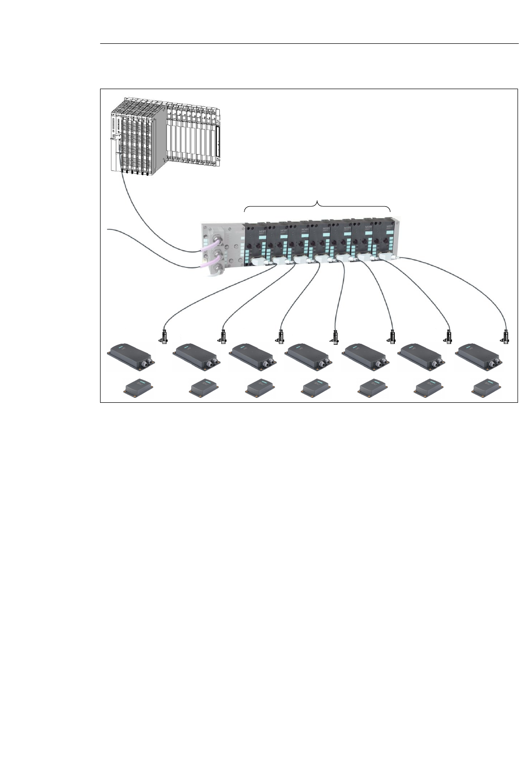
6-15
MOBY U – Manual for Configuration, Installation and Service
(4) J31069-D0139-U001-A2-7618
A max. of 7 ASM 473s can be op-
erated in one ET 200X.
Figure 6-11 Maximum configuration of ASM 473s on one ET 200X
Depending on the PROFIBUS master, up to 123 ET 200X modules can be
operated on one PROFIBUS branch.
The ASM 473 is integrated in the hardware configuration of SIMATIC
Manager by calling Setup.exe in the directory S7_OM\ASM473_OM on the
”MOBY Software” CD. At the moment the ASM 473 cannot be integrated on
the master of another manufacturer.
An SLG always occupies two M12 connection sockets (X3 and X4) on the
ASM 473. A prefabricated cable (cf. figure 6-4) makes it very easy to
connect the SLG. The standard version of the connection cable has a length
of 2 m. Other lengths are available on request. An SLG connection plug with
screw terminals (see figure 6-3) is available for users who want to make their
own cables. Cables and SLG connection plugs can be ordered from the
MOBY catalog.
Hardware
configuration
SLG connection
technology
Interfaces
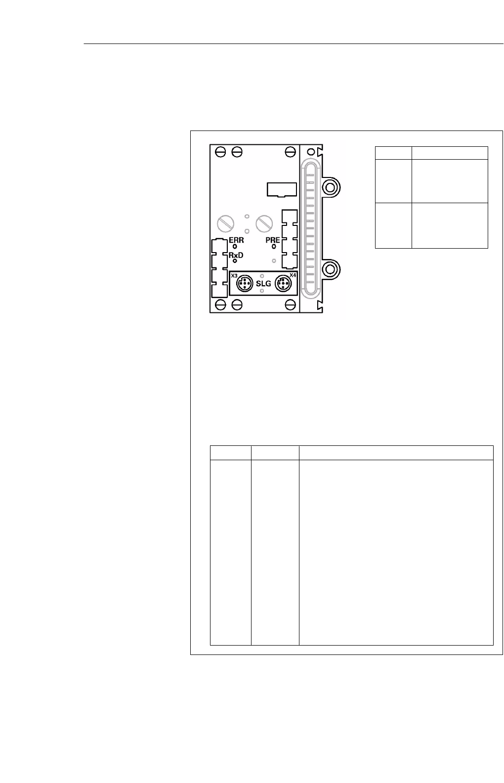
6-16 MOBY U – Manual for Configuration, Installation and Service
(4) J31069-D0139-U001-A2-7618
The following figure shows the pin allocation to the SLG and describes the
indicator elements.
ERR
ON (perm.)
OFF
OFF
2 Hz
5 Hz
1 flash
every 2
sec
PRE
OFF/ON
ON
2 Hz
2 Hz
5 Hz
OFF
Socket Pin Allocation (SLG)
1
2
3
4
5
+RxD
+TxD
–TxD
–RxD
PE
LEDs for PROFIBUS-DP
General operational indicators (SF, BF, ON, 24 V DC) are located on the
basic module of the ET 200X.
LEDs for MOBY
RxD: SLG is active with a command.
PRE: Indicates the presence of an MDS
ERR: Error indicated by flashing pattern (see chapter B.1)
x3
1
2
3
4
5
+24 V
n. c.
0 V
n. c.
PE
x4
The PRE and ERR LEDs indicate other operational states of the ASM.
Description, Causes, Remedies
Hardware is defective (RAM, Flash, etc.).
Loader is defective (can only be fixed at the plant).
Firmware loading procedure is active or no
firmware detected
→Load firmware.
→Don’t turn off ASM during this.
Firmware load terminated with error
→New start is required.
→Load firmware again.
→Check update files.
Operating system error
→Turn ASM or ET 200X basis station
off/on.
ASM has started up and is waiting for a RESET
(init_run) from the user.
Figure 6-12 Pin allocation and LEDs of the ASM 473
Pin allocations
Interfaces
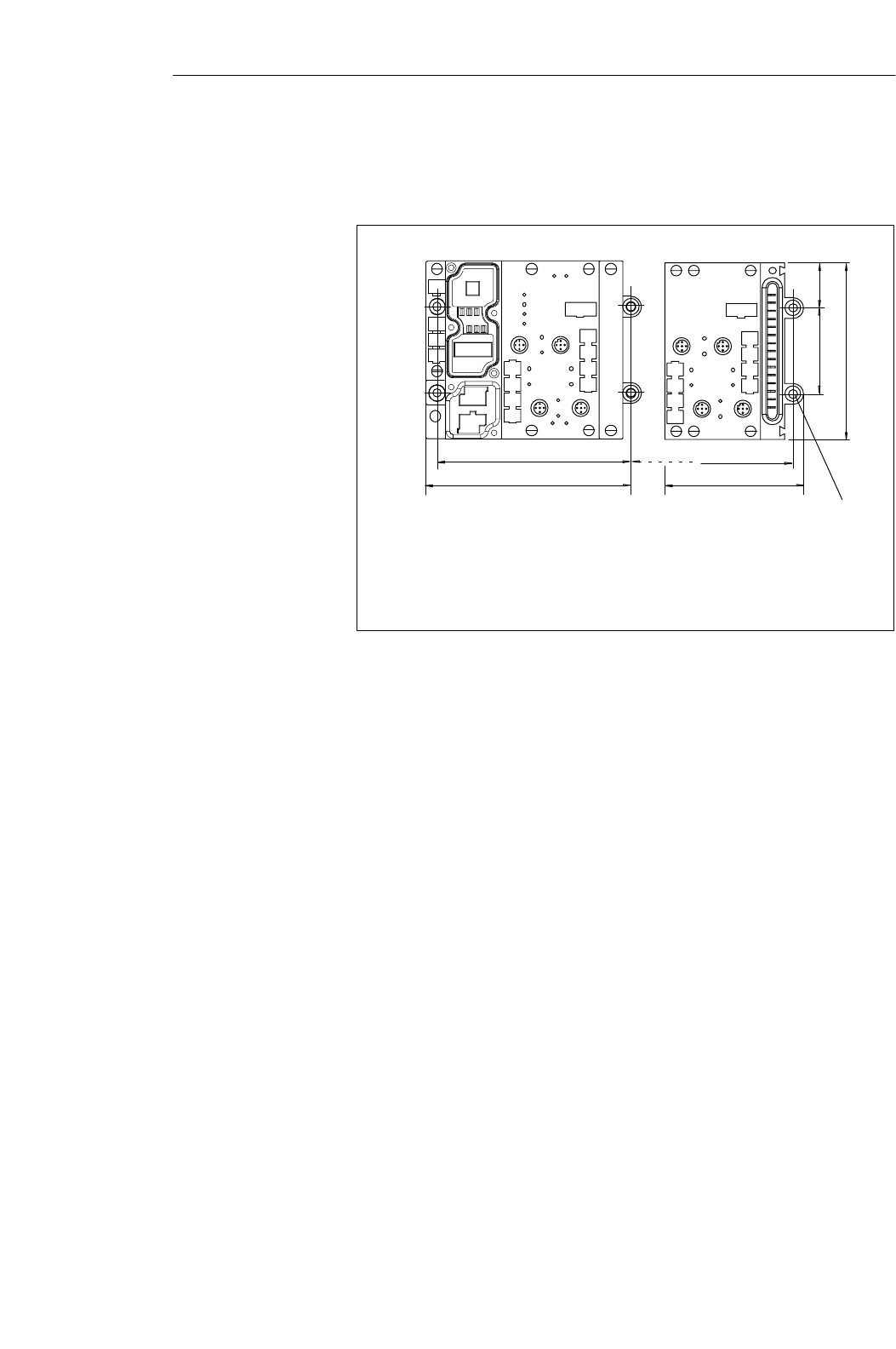
6-17
MOBY U – Manual for Configuration, Installation and Service
(4) J31069-D0139-U001-A2-7618
The figure below shows the dimensions for the positions of the holes for the
mounting screws for one basic module and one ASM 473 expansion module.
n 60
120
53.5
n = number of expansion modules
28.25
126.8
BM 141/142 ASM 473
87
110
For M5 mounting
screw
Figure 6-13 Dimensions for mounting holes for basic and expansion modules
Dimensional
drawing of
mounting holes
Interfaces
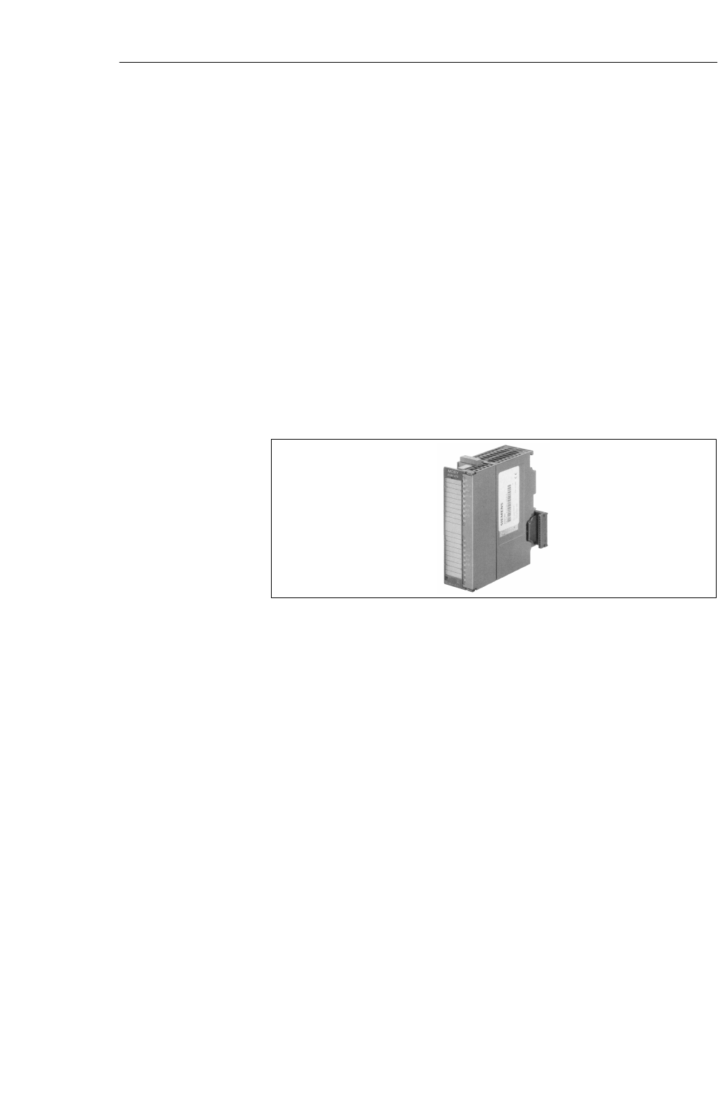
6-18 MOBY U – Manual for Configuration, Installation and Service
(4) J31069-D0139-U001-A2-7618
6.4 ASM 475
The ASM 475 interface module is a MOBY module which can be installed
on the SIMATIC S7–300 and ET 200M.
Up to eight ASM 475 interface modules can be installed and run in one mod-
ule rack of the SIMATIC S7–300. When a setup with several module racks
(max. of four) is used, the ASM 475 can be installed and run in every rack. In
its maximum configuration, one SIMATIC S7–300 can handle up to 32
ASMs centrally. The ASMs can just as well be run on the distributed I/O ET
200M on PROFIBUS. This makes operation in an S7–400 environment pos-
sible. Up to 7 ASMs can be run on one ET 200M.
Error messages and operational states are indicated with LEDs. The galvanic
isolation between SLG and the SIMATIC S7–300 bus permits interference–
immune operation.
Figure 6-14 Interface ASM 475
The ASM 475 is an interface module for communication between the
SIMATIC S7 and the SLG U92 with RS 422. The data on the MDS
U313/524/589can be addressed with the ASM 475 in the following ways.
SPhysical addressing (”normal” addressing) or
SWith a filehandler similar to DOS
The SIMATIC S7 offers a function for each of the two methods of access.
SFC 45 for ”normal” addressing
SFC 56 for Filehandler
FC 45 and FC 56 give the S7 user an easy–to–use interface with powerful
commands. FC 45 and FC 56 offer additional command chaining and S7 data
structures via UDTs.
Application area
Interfaces
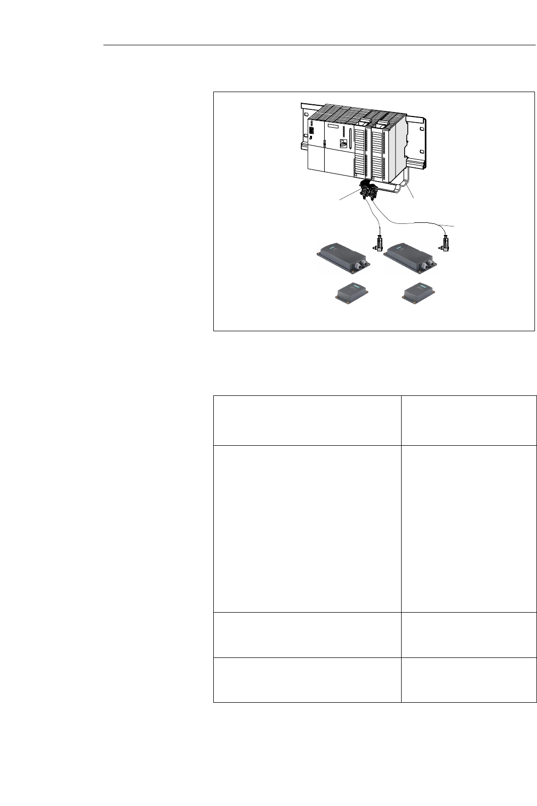
6-19
MOBY U – Manual for Configuration, Installation and Service
(4) J31069-D0139-U001-A2-7618
6GT2 091-0E...
ASM 475
SLG SLG
Shield connection terminal
(6ES7 390-5BA00-0AA0)
Shield connecting element
(6ES7 390-5AA00-0AA0)
for 2 modules
MDS MDS
Figure 6-15 Configurator for an ASM 475
Table 6-6 Ordering data for ASM 475
Interface ASM 475
for SIMATIC S7
2 x SLG U92 with RS 422 can be connected pa-
rallel, without front plug connector
6GT2 002-0GA00
Accessories:
Front plug connector (1 per ASM)
SLG cable, ASM 475 $ SLG
Lengths: 2 m, 5 m, 10 m, 20 m and 50 m
Optional: SLG cable, ASM 475 → SLG
with straight SLG plug
Shield connection terminal (1 per SLG cable)
Shield connecting element
MOBY Software 1)
with FC 45, FC 56, S7 Object Manager
6ES7 392-1AJ00 -0AA0
6GT2 091-0E...
6GT2 091-2E...
6ES7 390-5BA00 -0AA0
6ES7 390-5AA00 -0AA0
6GT2 080-2AA10
Description of FC 45 (for ASM 475)
deutsch
English
6GT2 097-3AM00-0DA1
6GT2 097-3AM00-0DA2
Description of FC 56 (for ASM 475)
deutsch
English
1) See chapter .7.1.
Ordering data
Interfaces
6-20 MOBY U – Manual for Configuration, Installation and Service
(4) J31069-D0139-U001-A2-7618
Table 6-7 Technical data of the ASM 475
ASM 475 with FC 45 ASM 475 with FC 56
Serial interface to
SIMATIC S7-300 or
ET 200M
Communication
Command buffer on ASM
475
P bus; cyclic and non–cyclic services
2 words (cyclic)/238 bytes (non–cyclic)
142 x 238 bytes per SLG U92
Serial interface to SLG
Plug connector With screw terminal on front plug connector
The front plug connector is included.
Line length, max. Prefabricated cables = 2 m, 5 m, 10 m,
50 m (up to 1000 m on request)
SLGs which can be connec-
ted 2x SLG U92 with RS 422
Parallel operation
Software functions
Programming Depends on PROFIBUS-DP master
Function blocks for
SIMATIC S7
MDS addressing
Commands
Multitag mode
S7 data structures with UDTs
FC 45
Access directly via ad-
dresses
Initialize MDS, read data
from MDS, write data to
MDS, and so on.
No
Yes
FC 56
Access via logical
file names (file system si-
milar to DOS)
Format MDS,
read file,
write file, etc.
Yes
Yes
Voltage
Nominal value
Permissible range
Current consumption
SWithout SLG at U =
24 V DC, max.
SWith connected SLGs,
max.
Power loss of the mo-
dule(typ.)
Current consumption from P
bus, max.
Potential isolation between
S7-300 and MOBY
24 V fuse to SLG
24 V DC
20.4 to 28.8 VDC
350 mA
500 mA, per connected SLG
2 W
80 mA
Yes, use own power pack for ground–free operation
for the ASM 475
Yes, electronic
Technical data
Interfaces
6-21
MOBY U – Manual for Configuration, Installation and Service
(4) J31069-D0139-U001-A2-7618
ASM 475 with FC 56ASM 475 with FC 45
Ambient temperature during
operation
SHorizontal setup of SI-
MATIC
SVertical setup of SIMA-
TIC
Transportation and storage
0 to +60 °C
0 to +40 °C
–40 to +70 °C
Dimensions (W x H x D) in
mm 40 x 125 x 120
Weight, approx. 0.2 kg
Wiring The ASM 475 is commissioned in the following steps.
SMount module
SMount module on profile rail of the S7–300
(see manual of the S7-300)
Note
Before mounting the module, switch the CPU of the S7–300 to STOP.
!Warning
Wire the S7–300 only when the power is off.
Note
To ensure interference–free operation of the ASM 475, make sure that ASM
and SIMATIC CPU (or ASM and IM 153 with ET 200M operation) use the
same voltage.
If not, error indicators which light up on the CPU when the ASM is turned
on may not go off.
Interfaces
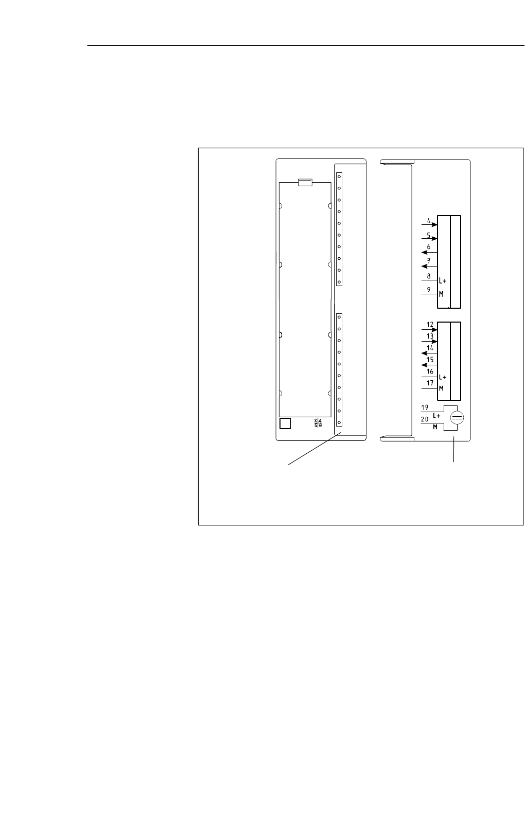
6-22 MOBY U – Manual for Configuration, Installation and Service
(4) J31069-D0139-U001-A2-7618
Front plate The following figure shows the front plate of the ASM 475 and the inside of
the front door with the connection diagram. The SLGs must be connected
with the ASM as shown in the connection diagram.
Status and error indicators
SLG 1
S+
S–
E+
E–
SLG 2
S+
S–
E+
E–
Connection diagram
The numbers for the
connection refer to plug
connector X1 of the
upper portion of the
housing.
ASM475/6 SF
DC5 V
ACT_1
ERR_1
PRE_1
RxD_1
ACT_2
ERR_2
PRE_2
RxD_2
6GT2 002-0GA10
MOBY
Figure 6-16 Front plate and inside of the front door of the ASM 475
Interfaces
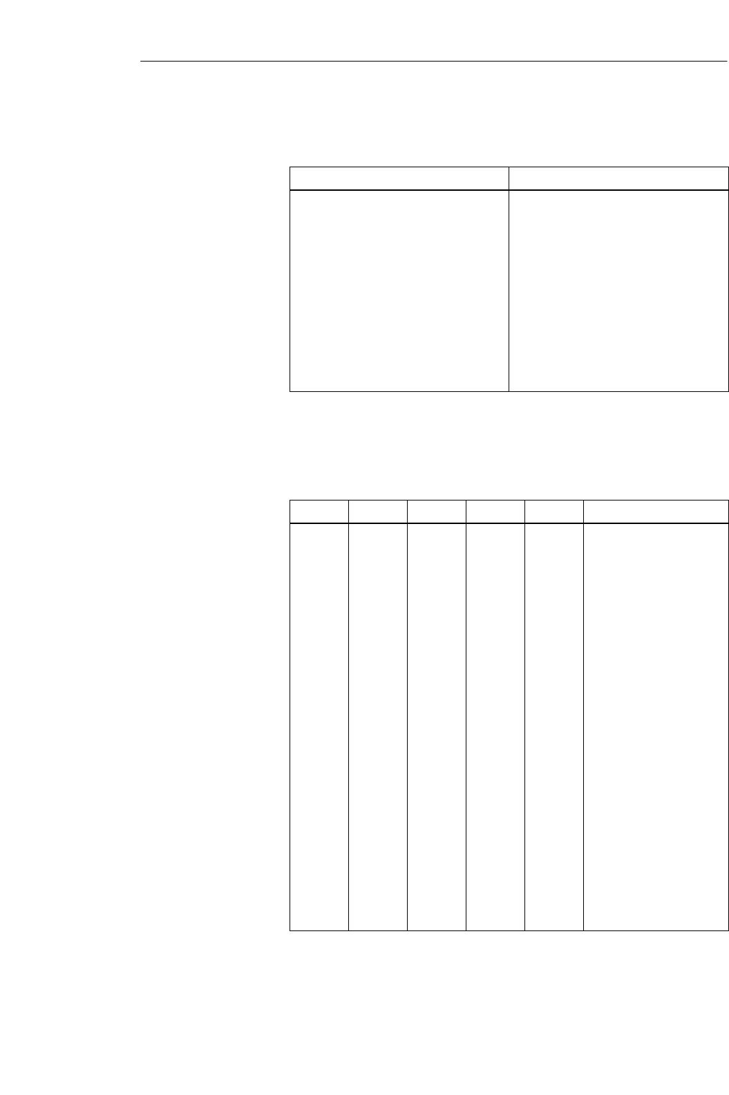
6-23
MOBY U – Manual for Configuration, Installation and Service
(4) J31069-D0139-U001-A2-7618
Table 6-8 Function of the LEDs on the ASM 475
LED Meaning
SF
5V DC System Fault (hardware error on ASM)
24 V are connected on ASM and the 5 V
on the ASM are okay.
ACT_1, ACT_2
Error 1 Error 2
y
The SLG is active with execution of a
user command.
A flashing pattern shows the error that oc-
E
rror_
1
,
E
rror_
2
PRE_1, PRE_2
A
fl
as
hi
ng pattern s
h
ows t
h
e error t
h
at oc-
curred last. This indicator can be reset
with the parameter Option_1.
Shows the presence of an MDS;
PRE
_
1
,
PRE
_
2
RxD_1, RxD_2
Shows
the
presence
of
an
MDS;
Indicates running communication with the
SLG; interference on SLG can also cause
this indicator to go on.
The LEDs PRE, ERR and SF on the ASM 475 indicate additional operating
states.
Table 6-9 Operating states shown by LEDs on the ASM 475
SF PRE_1 ERR_1 PRE_2 ERR_2 Meaning
ON
ON
OFF
OFF/ON
OFF
2 Hz
ON
(perm.)
ON
OFF
OFF/ON
OFF
2 Hz
ON
(perm.)
OFF
OFF
Hardware is defective
(RAM, Flash, etc.).
Loader is defective (can
only be fixed at the plant).
Firmware loading proce-
dure is active or no firm-
ware was detected.
– Load firmware.
– Don’t turn off
ASM during this.
OFF 2 Hz 2 Hz 2 Hz 2 Hz Firmware loading termina-
ted with error
– New start required
– Load firmware
again.
– Check update files.
Any 5 Hz 5 Hz 5 Hz 5 Hz Operating system error
– Turn ASM off/on.
OFF OFF 1 flash
every 2
sec
OFF 1 flash
every 2
sec
ASM has started up and is
waiting for a RESET
(init_run) from the user.
Indicator elements
on the ASM
Interfaces
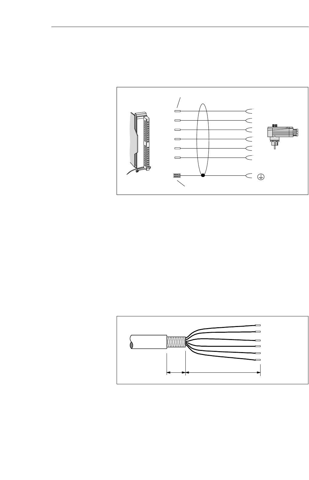
6-24 MOBY U – Manual for Configuration, Installation and Service
(4) J31069-D0139-U001-A2-7618
The following figure shows the design of a connection cable between ASM
and SLG. The specified colors apply to the standard MOBY cable for the
ASM 475.
SLG – plug
(socket)
Cable with core sleeves
White
Brown
Green
Yellow
Pink
Gray
(Shield)
6
1
4
5
2
3
4 (12)
5 (13)
6 (14)
7 (15)
8 (16)
9 (17)
Front plug
of the ASM
(6ES7 392-1AJ00-0AA0)
Cable shield open
Figure 6-17 Wiring of the ASM 475 to the SLG U92 with RS 422 (6GT2 091-0E...)
See figure 3-12 or 6-15.
Implement lightning rods and grounding measures if required for your
application. Protection against lightning always requires an individual look at
the entire plant.
To ensure EMC, the SLG cable must be led over an S7–300 shield
connecting element (see figure 6-15). When customers make their own
cables, the shield of the SLG cable must be bared as shown in figure 6-18.
Specifications in mm
30 170
Figure 6-18 Baring of the cable shield for customer–fabricated cable
Wiring to the SLG
Shield connection
Lightning rods
Cable fabrication
by the customer
Interfaces
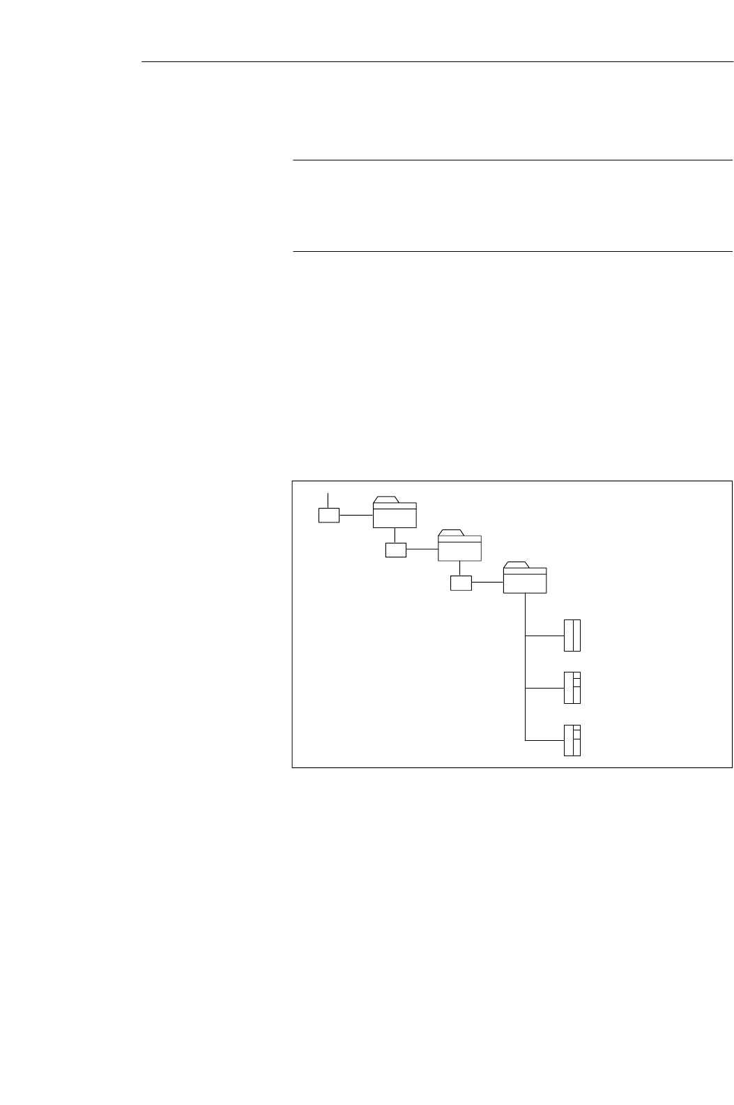
6-25
MOBY U – Manual for Configuration, Installation and Service
(4) J31069-D0139-U001-A2-7618
Note
Installation of MOBY requires functional STEP 7 software on a PC/PG.
Please remember to use the latest version of STEP 7. At the moment, you
will need STEP 7 V 5.1 Service Pack 3 for MOBY U operation.
Installation and configuration of the ASM 475 in the SIMATIC is performed
with an installation program. The installation program is included on the
”MOBY Software” product (6GT2 080-2AA10).
The installation files are located in subdirectory S7_om on the MOBY
software CD. Most of the installation is automatic after Setup.exe is called.
The specified steps during SETUP must be answered.
See the ASM 475 module in the hardware catalog of HW Config in the fol-
lowing subdirectory for hardware configuration of the SIMATIC S7.
SIMATIC 300
SM 300
Special 300
MOBY ASM470
MOBY ASM475
MOBY ASM476
Figure 6-19 ASM 475 directory in the hardware catalog
Configuration of
the ASM for
SIMATIC S7 under
STEP 7
Installation
Interfaces

6-26 MOBY U – Manual for Configuration, Installation and Service
(4) J31069-D0139-U001-A2-7618
You can use the ”file dearchivation” function of SIMATIC Manager to load
the FC with a sample project from the applicable subdirectory of ”MOBY
Software.” The sample project is located in the S7PROJ directory of
SIMATIC Manager.
Directory in MOBY Soft-
ware Project Name in SIMATIC
Manager Path Name in SIMATIC
Manager
FC 45 MOBY FC45 Moby_f_l
FC 56*
* Under preparation
FC 45/56 with
sample project
Interfaces
7-1
MOBY U – Manual for Configuration, Installation and Service
(4) J31069-D0139-U001-A2-7618
Accessories 7

7-2 MOBY U – Manual for Configuration, Installation and Service
(4) J31069-D0139-U001-A2-7618
7.1 MOBY Software
The ”MOBY Software” product is delivered on CD. It contains all function
blocks and drivers for the MOBY system. The software components and their
documentation are described briefly in the file ”Read_me.txt” in the main
directory of the CD.
The software components on the CD which are relevant to MOBY U are
listed below.
SFC 45
SIMATIC S7 function for ASM 452 / 473 / 475
SFC 46
SIMATIC S7 function for ASM 452
SFC 56 for ASM 452/473/475 1
SMOBY_lib MOBY API
MOBY API application interface with the 3964R driver for
Windows 98/2000/NT 4.0
SManuals
Current status of MOBY documentation in PDF format
SS7-om
Installation program and Object Manager for interface modules ASM 473
and ASM 475
Sample projects are installed here with the appropriate FCs. These are
located in the applicable FC directories.
SDemo
Test and demo programs for PC with Windows 98/2000/NT 4.0
STools
Useful programs for MOBY configuration are located here.
SShort descriptions of the individual directories in German or English (cf.
“Les_mich.txt” or “Read_me.txt”).
SProfi_gsd
PROFIBUS master device files for ASM 452
Only the components related to MOBY U are specified from all the software
components (i.e., the complete MOBY system is not included).
Note
You will need at least version 3.4 of the MOBY Software CD to run MOBY
U.
1 Under preparation
Accessories
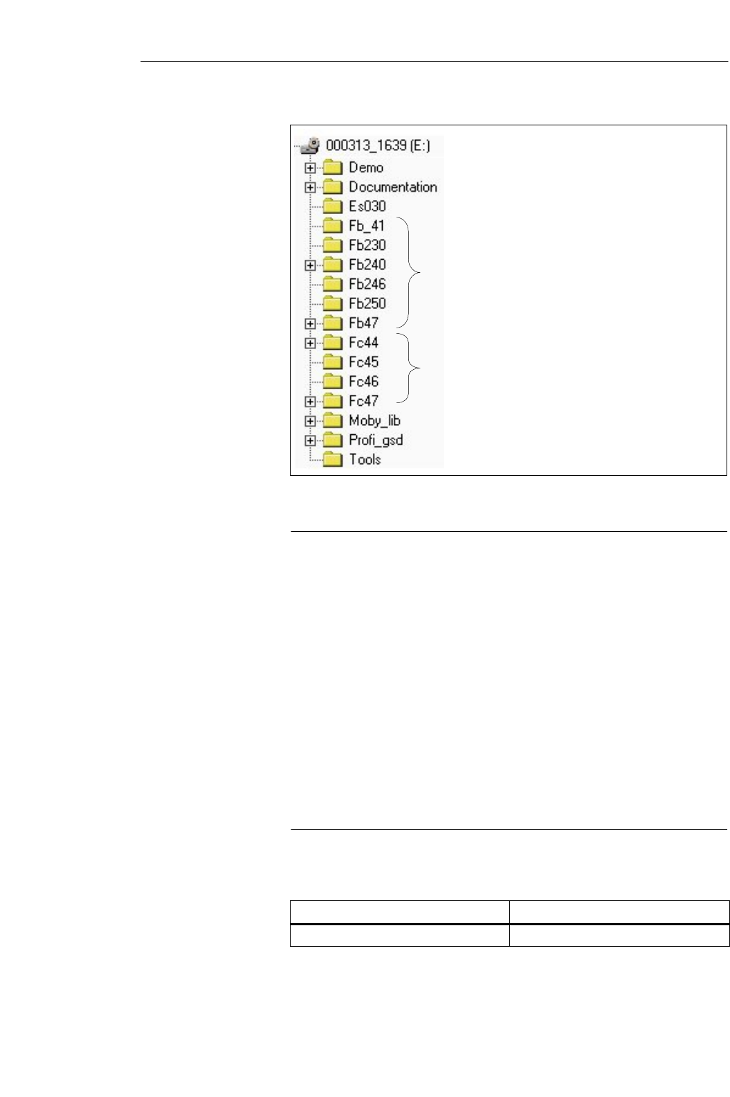
7-3
MOBY U – Manual for Configuration, Installation and Service
(4) J31069-D0139-U001-A2-7618
C libraries and 3964 R drivers
Complete MOBY documentation
Function blocks for SIMATIC S5
Functions for SIMATIC S7
Auxiliary programs for the configuration
PROFIBUS device master files
Figure 7-1 Program directories of ”MOBY Software,” release V 3.0
Note
On MOBY software or licensing
When you purchase an ASM or SLG interface module, this does not include
software or documentation. The CD-ROM “MOBY Software,” which con-
tains all available FBs/FCs for the SIMATIC, C libraries for Windows
98/2000/NT, demo programs and so on must be ordered separately. In
addition, the CD–ROM contains the complete MOBY documentation (Ger-
man and English) in PDF format.
When you purchase an ASM or SLG interface module, the price for use of
the software including documentation on the ”MOBY Software” CD–ROM
is included. The purchaser obtains the right to make copies (duplication li-
cense) as needed for customer applications or system development for the
plant.
In addition, the enclosed contract is valid for the use of software prod-
ucts against a one–time payment.
Table 7-1 Ordering data for MOBY Software
Order No.
MOBY Software 6GT2 080-2AA10
Ordering data
Accessories
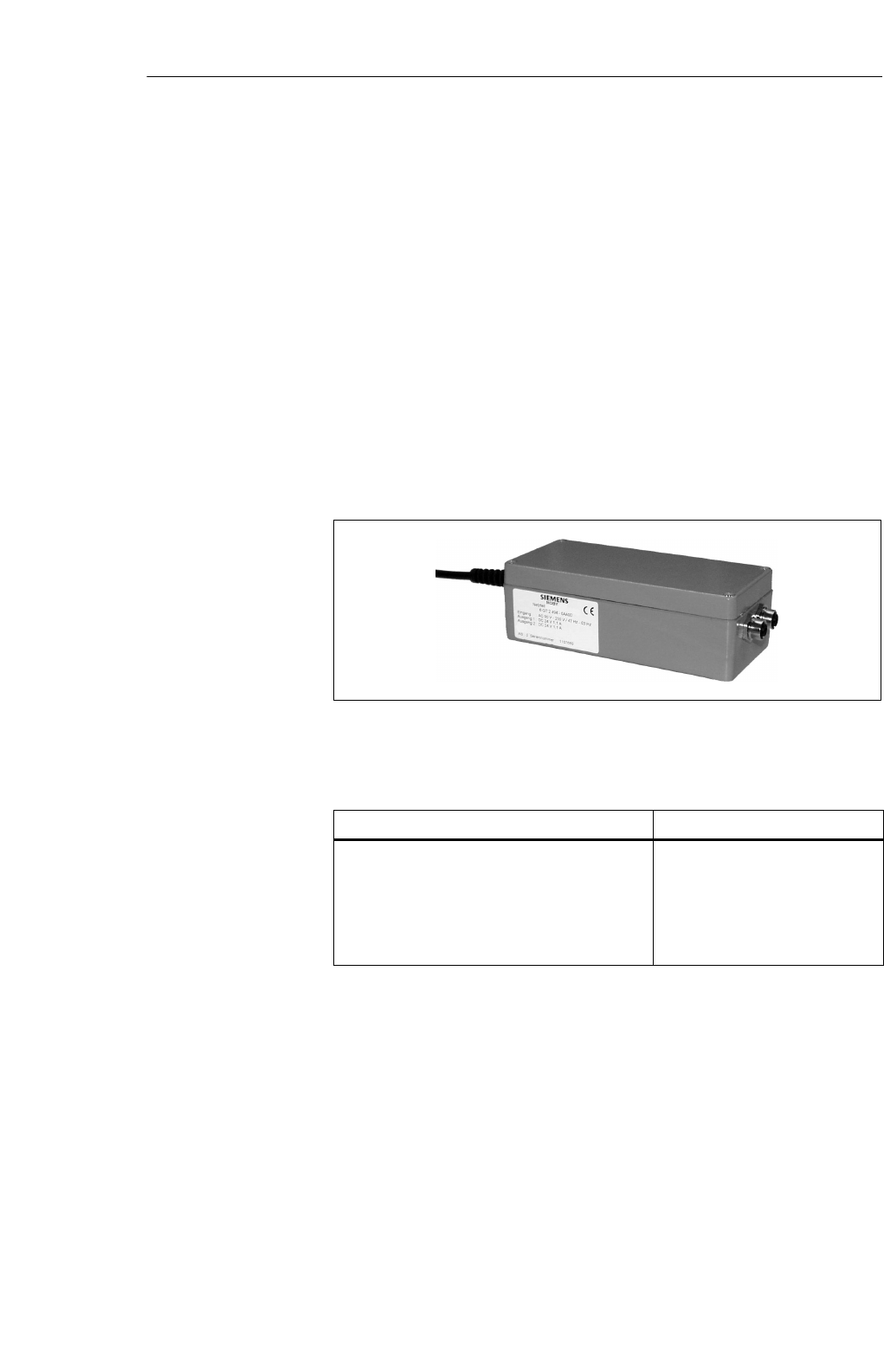
7-4 MOBY U – Manual for Configuration, Installation and Service
(4) J31069-D0139-U001-A2-7618
7.2 MOBY Wide–Range Power Pack
The MOBYR wide–range power pack is a compact, primary–pulsed power
supply, designed for use on single–phase, alternating current networks with
two DC outputs (socket plug connector, circuited in parallel).
The robust physical construction is comprised of an aluminum housing which
gives the finely–adjusted system a good blend of physical strength, protection
against electromagnetic interference and optimum heat dissipation.
The primary–pulsed power supply is protected against overload with a
built–in power limitation circuit and is permanently short–circuit proof.
The standardly integrated overvoltage fuse (SIOV) protects the electronics
from excessively high voltages. Two SLG U92s can be directly connected to
the MOBY wide–range power pack. You will also need the connection cable
6GT2 591-1C... (see chap. 3.6.2) for this.
Figure 7-2 MOBY wide–range power pack
Table 7-2 Ordering data for MOBY wide–range power pack
Order No.
MOBY wide–range power pack, 100 - 230 V
AC/24 V DC/2.2 A; incl. 2 counterplugs for the
output voltage
Accessories:
24 V stub line for SLG U92 with RS 232; length
of 5 m, extension for 6GT2 591-1C...
6GT2 494-0AA00
6GT2 491-1HH50
Description
Ordering data
Accessories

7-5
MOBY U – Manual for Configuration, Installation and Service
(4) J31069-D0139-U001-A2-7618
Table 7-3 Technical data of the MOBY wide–range power pack
Input
Input voltage
Nominal value
Range
Frequency
Input current
Efficiency
Power connection
Power failure bypass
Undervoltage switchoff
Overvoltage protection
100 - 230 V AC
90 - 253 V AC
50/60 Hz
0.85 - 0.45 A
w 80 % at full load
2–m power line with fuse contact
plug
w 10 msec
Yes
SIOV
Output
Nominal output voltage
Nominal output current
Residual ripple
Startup current limitation
Permanent short–circuit proof
Socket contacts
24 V DC
2.2 A
20 mVss to 160 kHz
50 mVss > 160 kHz
NTC
Yes
Ambient conditions
Ambient temperature
Operation
Transportation and storage
Cooling
-20 _C to +40 _C
(max. of +60 _C; see notes on sa-
fety)
-40 _C to +80 _C
Convection
General information
Dimensions, power supply incl. mounting plate,
(L x W x H) in mm
Weight
Color
205 x 80 x 60
(without connection plugs)
Approx. 1000 g
Anthracite
Electromagnetic compatibility
Interference emission (EN 50081-1)
Interference immunity (EN 50082-2) Class B in acc. w. EN 55022
EN 61000-4-2
Safety
Certifications
Electrical safety test
Potential isolation, primary/secondary
Protection class
Protection rating
CE, GS
EN 60950/VDE 0805 and
VDE 106 (part 1)
4 kV AC
I, in acc. w. EN 60950 (VDE
0805)
IP 65, in acc. w. EN 60529 (only
when installed)
Technical data
Accessories
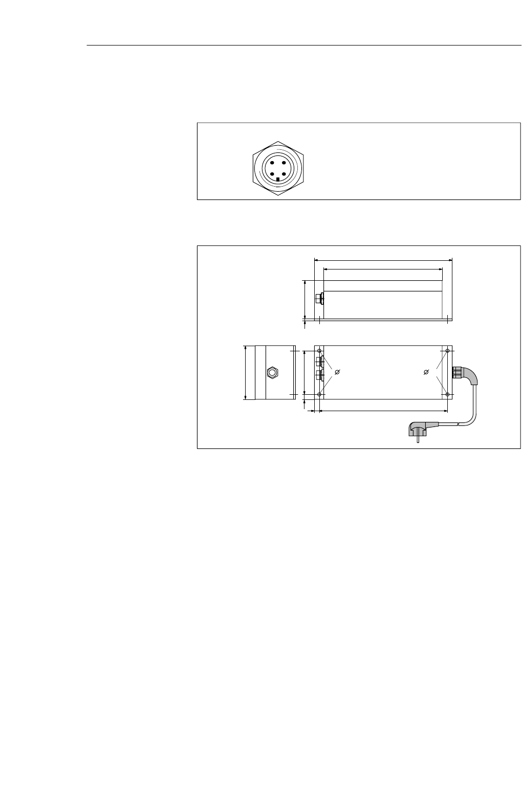
7-6 MOBY U – Manual for Configuration, Installation and Service
(4) J31069-D0139-U001-A2-7618
2
3
1
4
Outputs 1 and 2:
Socket 1: Ground (0 V)
Socket 2: +24 V DC
Socket 3: +24 V DC
Socket 4: Ground (0 V)
Figure 7-3 Plug allocation of 24 V output
80
7.5 65
190
7.5
176
205
573
5 5
Figure 7-4 Dimensions of MOBY wide–range power pack
Plug allocation of
24 V output
Dimensions (in
mm)
Accessories

7-7
MOBY U – Manual for Configuration, Installation and Service
(4) J31069-D0139-U001-A2-7618
!Caution
Do not open the devices or modify them.
Failure to adhere will invalidate the CE and the manufacturer’s warranty.
Applicable DIN/VDE regulations or country–specific specifications must be
observed when installing the power pack.
The application area of the power pack is limited to ”information technology
of electrical office machines” as described in the standard EN 60950/VDE
0805.
A device may only be commissioned and operated by qualified personnel.
For the purposes of this manual, qualified personnel are persons who are
authorized to commission, ground and tag devices, systems and electrical
circuits in accordance with safety standards. The device may only be used
for the applications described in the catalog and the technical description
and then only with Siemens devices and components or devices or compo-
nents of other manufacturers recommended by Siemens.
Correct operation of the product is dependent on correct storage, setup and
installation as well as careful use and maintenance.
During installation, make sure that sufficient space is available so that the
electrical output can be accessed.
The housing may heat up during operation to up to +40 °C and this is no
cause for worry. However, make sure that the power pack is covered when
the ambient temperature exceeds +40 °C to protect people from touching the
excessively hot housing. The power pack must also have sufficient ventila-
tion.
Notes on safety
Accessories

7-8 MOBY U – Manual for Configuration, Installation and Service
(4) J31069-D0139-U001-A2-7618
Accessories

A-1
MOBY U – Manual for Configuration, Installation and Service
(4) J31069-D0139-U001-A2-7618
Documentation
Table A-1 Ordering data for descriptions
Order No.
Description of FC 45
deutsch
English 6GT2 097-3AM00-0DA1
6GT2 097-3AM00-0DA2
Description of ASM 452/PC 46
deutsch
English 6GT2 097-3AC40-0DA1
6GT2 097-3AC40-0DA2
Description of ASM 475/FC 45/FC 56
for SIMATIC S7
deutsch
English
Description of ASM 473
Description of 3964 R for
Win 95/NT (German/English) On MOBY Software CD
Description of MOBY API On MOBY Software CD
Description of MDS U589
deutsch
English
Descriptions,
bound
A

A-2 MOBY U – Manual for Configuration, Installation and Service
(4) J31069-D0139-U001-A2-7618
Documentation
B-1
MOBY U – Manual for Configuration, Installation and Service
(4) J31069-D0139-U001-A2-7618
Error Messages
This chapter gives you the error messages of MOBY U. The messages are
divided into three groups.
B.1 This section covers the messages with the error numbers 01 hex to 1F
hex. These messages apply to all interfaces and SLG U92s which use
direct MDS addressing.
B.2 Function blocks (e.g., FC 45) output additional messages on the status
of the hardware. These special messages are described in this section.
B.3 The third section covers the filehandler messages. The messages apply
to the ASM 452 with FC 46/56 and the ASM 475 with FC 56.
B

B-2 MOBY U – Manual for Configuration, Installation and Service
(4) J31069-D0139-U001-A2-7618
B.1 General Errors
The following error codes may occur during MOBY U operation. The error
codes are transferred during telegram communication in the status byte or are
indicated by the red LED on the front plate. This LED shows the last error
(for most ASMs) permanently even when this error has already been cor-
rected.
With FC 45, this error code is indicated in the ”error_MOBY” variables.
Error Messa
g
es
B-3
MOBY U – Manual for Configuration, Installation and Service
(4) J31069-D0139-U001-A2-7618
Table B-1 General errors
Error
Code in
Hex
LED
Indicatio
n
Cause, Remedy
00
–
01
02
03
04
05
00
01
02
02
03
04
05
Not an error; result is okay.
See error code 0F.
Presence error: MDS has moved out of the transmission window of SLG. The MOBY
command was only partially executed.
Read command: No data are supplied to the computer.
Write command: The data memory which just left the field has an incomplete data
record.
! Sa (working distance from SLG to MDS) is not adhered to.
! Configuration error: Data block to be processed is too large (for dynamic operation).
The next command (READ, WRITE, NEXT) is automatically assigned to the next MDS.
Remarks:
The error indication with the red LED on the front plate shows error code 02 this time.
Presence error:
!A mobile data memory moved past the SLG but wasn’t processed with a command or
concluded with a NEXT command.
!An INIT command was terminated with RESET.
This error message cannot be given until the next command (read, write, status, RESET,
DI/DO, or NEXT). Although the command is not executed, this error message is genera-
ted. The ASM then executes the next command normally. Error 02 is reported immediately
via external diagnosis.
Remarks:
The red error LED showing the errors does not distinguish between error 01 and error 02
(see error code 01).
Errors in connection with the SLG
! Voltage of ASM < 20 V or ASM not connected
! 24 V has voltage drops.
! Fuse on the ASM has blown. Check wiring.
! Cable wired wrong between ASM and SLG or cable break
! Hardware defective: ASM or SLG
! Other SLG in the vicinity is active.
! Interference on SLG cable or bus cable
Error in memory of MDS
The data memory has never been written or has lost its contents due to battery failure.
! Initialize data memory with the STG
! With the ASM: Call initialization command.
! Check battery of MDS or change MDS (battery bit).
! Data memory is defective.
! Initialization was performed with wrong memory size.
– Unknown command code in byte 2 of the telegram
– The MDS reported address error (check telegram).
Error Messa
g
es

B-4 MOBY U – Manual for Configuration, Installation and Service
(4) J31069-D0139-U001-A2-7618
Table B-1 General errors
Error
Code in
Hex
Cause, RemedyLED
Indicatio
n
06
07
08
09
0A
0B
0C
0D
0E
06
07
08
09
10
11
12
13
14
Field interference on SLG
The SLG is receiving interference from its surroundings.
!External interference field. The field of interference can be localized with the ”
inductive field indicator” of the STG.
!The distance between two SLGs is too small and does not adhere to configuration
guidelines.
!The connection cable to the SLG is faulty, too long or does not meet specifications.
Too many sending errors
The MDS was unable to receive the command or the write data from the SLG even after
several attempts.
! The MDS is positioned on the boundary of the transmission window.
! Data transmission to the MDS is being bothered by external interference.
CRC sending error
– The monitor receiving circuit detected an error while sending.
! Same cause as for error 06
– The MDS reports CRC errors very frequently.
! The MDS is located on the boundary of the SLG.
! The MDS and/or the SLG have a hardware defect.
Only for initialization: CRC error while receiving the acknowledgment from the MDS
! Same cause as for error 06
Only for initialization: MDS is unable to execute INIT command.
! MDS is defective.
Only for initialization: Timeout while initializing the MDS
!The MDS is located on the boundary of the transmission window.
!The MDS is using too much current (defective).
!Only with MDS 507/407E: MDS 507/407E mode was not enabled with the ”RESET
with parameter transfer” command.
Memory of the MDS cannot be written.
! Memory of the MDS is defective.
! EEPROM-MDS was written too often and has reached the end of its life.
! Wrong end address was parameterized with INIT command.
Address error (address area exceeded)
! Specified address doesn’t exist on the MDS.
! Check and correct command for telegram structure.
! Status byte of command is not 00.
ECC error
The data cannot be read from the MDS.
! MDS data have been lost (MDS defective).
! The MDS was not initialized with ECC driver.
!Initialize MDS.
!MDS with EEPROM has reached the end of its life. The data have been lost.
!Replace MDS.
! The MDS moved out of the field while being written.
!The MDS is positioned incorrectly.
! User sent wrong command to ASM.
Error Messa
g
es
B-5
MOBY U – Manual for Configuration, Installation and Service
(4) J31069-D0139-U001-A2-7618
Table B-1 General errors
Error
Code in
Hex
Cause, RemedyLED
Indicatio
n
0F
10
11
12
14
15
16
17
18
01
16
17
18
20
21
22
23
24
Startup message
The ASM sends this message after every startup. (A startup occurs each time the voltage is
applied, each time the front switch is activated, after a reset via plug X1 or after a bus er-
ror.) The startup message remains queued until the user sends a RESET command to the
ASM. This gives the user a chance to know when power returns to the ASM (i.e., ASM is
ready again).
NEXT command is not possible or not permitted.
! ASM is not using the presence check.
! ASM has already received a NEXT command.
Short circuit or overload of the 24 V outputs
Next command must be a RESET command.
!The affected output is turned off.
!All 24 V outputs are switched off if overload is total.
!Reset can only be performed by turning the power off and on again.
Internal ASM communication error
Connection to the MOBY processor is faulty. Next command must be a RESET command.
! Hardware of ASM defective
! Disturbing EMC interference
Internal ASM error
Stack overflow. Next command must be a RESET command.
! Turn 24 V power off and on again.
Wrong operational parameterization/RESET parameter has a mistake.
! Check switch on ASM.
! Check RESET command.
The command cannot be executed with the current bus configuration.
! Input or output areas are too small for the size of the telegram.
! Length specified in read or write command is too long.
! Adapt bus configuration on the master module.
Handshake error
Next command must be a RESET command.
!During the handshake, user set a wrong bit in the command byte of the telegram.
! Check user program and correct.
Only RESET command permitted
!An error occurred which must be acknowledged with a RESET command (cause can
be a brief short circuit on PROFIBUS).
Error Messa
g
es
B-6 MOBY U – Manual for Configuration, Installation and Service
(4) J31069-D0139-U001-A2-7618
Table B-1 General errors
Error
Code in
Hex
Cause, RemedyLED
Indicatio
n
19
1A
1C
1D
1E
1F
20
(binary
xx1x xxxx)
40
(binary
x1xx xxxx)
80
(binary
1xxx xxxx)
25
26
28
29
30
31
32
64
128
Previous command active
A new command was sent to the ASM/SLG although the last command is still active.
! An active command can only be terminated with a RESET command.
! The new command is concluded with error 19hex. The old command is being executed
by the ASM/SLG and will be reported as finished afterwards.
PROFIBUS-DP error occurred
! Bus connection is interrupted (wire break, plug pulled).
! Master won’t address ASM anymore.
! The error is reported as soon as the bus connection is okay again.
– The telegram doesn’t have the correct format.
! Antenna is already off.
! Antenna is already on.
! Mode in SET–ANT command is unknown.
! Antenna cannot be turned off since an MDS command is still waiting.
! Antenna is off. The MDS command cannot be executed.
Number of MDSs in the field of the SLG > number of MDSs in the bunch specified in the
RESET command.
AB byte doesn’t correspond to user data length.
! Check and correct the telegrams in the user program.
Communication with the MDS was terminated with RESET. This error can only be retur-
ned with a RESET command.
No error message!
Only occurs when an enabled ECC driver is being used. It indicates that the driver found a
1–bit error and corrected it. The read or written data are okay.
No error message!
Usually this bit is always set. It is reserved to indicate the status of a 2nd battery on the
MDS.
No error message!
Battery power of the MDS has fallen below the threshold value. We recommend changing
the MDS immediately.
This status bit is always set with EEPROM–MDSs.
With SINUMERIK, the battery message does not have an ”F” in IDENTIFICATION. The
”fnr” field can be evaluated in one place for the complete system to detect a weak battery.
2 If several states occur at the same time, the following sequence applies: 0052, 0050, 0051
Error Messa
g
es

B-7
MOBY U – Manual for Configuration, Installation and Service
(4) J31069-D0139-U001-A2-7618
B.2 ASM–Specific Errors
B.2.1 Error Indicators in FC 45
The FC 45 indicates the error codes with 3 variables.
Serror_MOBY:
MOBY errors in table B-1
Serror_FC:
Errors supplied by FC 45 due to incorrect
parameterization (cf. table B-2)
Serror_BUS:
Errors reported by system functions
SFC 58/59 (cf. table B-3)
Table B-2 error_FCerror variable
error_FC
(B#8#..) Description
00 Not an error; standard value when everything is okay.
01 Params_DB doesn’t exist on the SIMATIC.
02 Params_DB is too small.
⇒UDT 10/11 was not used in the definition.
⇒Params_DB must be 300 bytes long (for each channel).
⇒Check Params_DB, Params_ADDR for correctness.
03 The DB after the pointer “command_DB_number” doesn’t exist on the SIMATIC.
04 “Command_DB” on SIMATIC is too small.
⇒UDT 20/21 was not used in the command definition.
⇒The last command in “command_DB” is a chained command. Reset the chaining bit.
05 Invalid type of command
06 The received acknowledgment is not the expected acknowledgment. The parameters of the command
and acknowledgment telegrams do not match (command, length, address_MDS).
⇒The user changed the pointer command_DB_number/
-_address while the command was being executed.
⇒The user changed the command parameters in the MOBY CMD data block (UDT 20) while
the command was being executed.
07 The parameter MOBY_mode (defined in UDT 10) has an illegal value.
08 A bus error has occurred which was reported by system
functions SFC 58/59. More information on the error is available in the variable error_Bus.
Error Messa
g
es
B-8 MOBY U – Manual for Configuration, Installation and Service
(4) J31069-D0139-U001-A2-7618
Table B-2 error_FCerror variable
error_FC
(B#8#..) Description
09 The ASM has failed.
⇒Power failure on MOBY ASM
⇒PROFIBUS plug pulled or PROFIBUS cable broken
The error is indicated when the ASM_Failure bit was set in OB 122. OB 122 is called when the FC
45 can no longer access the cyclic word for the MOBY ASM.
0A The user started another init_run without waiting for ready while the first init_run command was still
being processed.
⇒Do not set init_run cyclically.
0B init_run cannot be executed. Cyclic process image for ASM is faulty. FC 45 reports timeout of PII
(This error can be fixed by writing the value #00 to address DBB 58 in UDT 10. However, in certain
error situations, the FC 45s don’t generate an error message and get hung up.)
⇒ASM_address in UDT 10 is parameterized incorrectly. ASM_address may be pointing to the
wrong module.
⇒ASM hardware/firmware is faulty.
0C Area length error. error_BUS has the error 8x22 or 8x23.
⇒DAT_DB does not exist or is too small. Check DAT_DB_number and
DAT_DB_address in UDT 20.
⇒ Perform init_run.
Table B-3 Error variable error_Bus
Error code
(W#16#...) Description
800A ASM is not ready (temporary message).
⇒This message is sent to a user who is not using the FC 45 but non–cyclically polls the ASM in
very quick succession.
8x7F Internal error in parameter x. Cannot be corrected by the user.
8x22
8x23 Area length error while reading a parameter
Area length error while writing a parameter
This error code indicates that parameter x is completely or partially outside the operand range or the
length of a bit field in an ANY parameter is not divisible by 8.
8x24
8x25 Area error while reading a parameter
Area error while writing a parameter
This error code indicates that parameter x is located in an area which is illegal for the system func-
tion.
8x26 The parameter contains number of a time cell which is too large.
8x27 The parameter contains number of a counter cell which is too large.
8x28
8x29 Direction error while reading a parameter
Direction error while writing a parameter
The reference to parameter x is an operand whose bit address is not 0.
Error Messa
g
es

B-9
MOBY U – Manual for Configuration, Installation and Service
(4) J31069-D0139-U001-A2-7618
Table B-3 Error variable error_Bus
Error code
(W#16#...) Description
8x30
8x31 The parameter is located in the write–protected global DB.
The parameter is located in the write–protected instance DB.
8x32
8x34
8x35
The parameter has a DB number that is too large.
The parameter has an FC number that is too large.
The parameter has an FB number that is too large.
8x3A
8x3C
8x3E
The parameter has the number of a DB which is not loaded.
The parameter has the number of an FC which is not loaded.
The parameter has the number of an FB which is not loaded.
8x42
8x43
An access error occurred while the system was trying to read a parameter from the I/O area of the
inputs. An access error occurred while the system was trying to write a parameter to the I/O area of
the outputs.
8x44
8x45 Error during nth (n > 1) read access after an error occurred
Error during nth (n > 1) write access after an error occurred
8090 Specified logical base address is invalid. There is no allocation in SDB1/SDB2x or this is not a base
address.
8092 A type other than BYTE was specified in an ANY reference.
8093 The area identifier obtained when the logical address was configured (SDB1, SDB2x) is not permit-
ted for these SFCs. Permissible are:
0 = S7-400
1 = S7-300
2.7 = DP modules
80A0 Negative acknowledgment while read–accessing module. (Module was pulled during read access or
module is defective.)
80A1 Negative acknowledgment while write–accessing the module. (Module was pulled during write ac-
cess or module is defective.)
80A2 DP protocol error for layer 2, possible hardware defect.
80A3 DP protocol error with direct–data–link–mapper or user interface/user, possible hardware error.
80B0 SSFC for this type of module not possible
SModule doesn’t know the data record.
SData record number ≥ 241 is illegal.
SData records 0 and 1 are not permitted with SFC58 “WR_REC.”
80B1 The length specified in the RECORD parameter is wrong.
80B2 The configured slot is not occupied.
80B3 The actual module type is not the required module type in SDB1.
80C0 SRD REC: The module has the data record but no read data have arrived yet.
SWR REC: ASM is not ready to receive new data.
⇒ Wait for the cyclic counter to count up.
80C1 The data of the preceding write job on the module for the same data record have not yet been proces-
sed by the module.
80C2 The module is processing the maximum possible number of jobs for one CPU.
80C3 Required resources (memory, etc.) are busy at the moment.
Error Messa
g
es

B-10 MOBY U – Manual for Configuration, Installation and Service
(4) J31069-D0139-U001-A2-7618
Table B-3 Error variable error_Bus
Error code
(W#16#...) Description
80C4 Communication error:
SParity error
SSW ready not set
SError in block length management
SChecksum error on CPU side
SChecksum error on module side
80C5 Distributed I/O not available
Error Messa
g
es

B-11
MOBY U – Manual for Configuration, Installation and Service
(4) J31069-D0139-U001-A2-7618
B.3 Filehandler Error Messages for ASM 452/475
The command ID of the started command is illegal (not defined). The correct
KK must be specified.
The telegram control parameters (DBN or KK) are not in the correct
sequence. Two or more telegrams are written to the same page frame
memory area. Parameterization of the FB call parameters ”SSNR” and
”KAN” of all channels must be checked.
S1st command block: DBN (= byte 8/9 in telegram) is not 0001.
SNext block: DBN of user is not in the correct ascending order or the KK
parameter (byte 4) doesn’t fit the command which was just executed.
Checkbyte mode is on. The checkbyte generated by FB 230 doesn’t fit the
command telegram. Error correction same as A0 11.
The filehandler is now processing the commands of another user (e.g., STG,
indicated by bit 6 ”STG active/ASM test” of BEST). Command execution
will be delayed until the other user is finished. If necessary, start the
command again.
Error in connection to the SLG
SCable between ASM and SLG is incorrectly wired or there is a cable
break.
S24 V power is not connected or turned off.
SHardware defective: Channel module or SLG
This error does not occur when the system commands (RESET, NEXT, ASM-
STATUS) are started.
EAKO 1: - A command was started but there is no MDS in the
SLG’s transmission window.
EAKO 0: - The old/current MDS has moved out of the transmission
window and the next/new MDS has entered the
transmission window. A command was started
(not NEXT). This command refers to the new MDS but
the old/current MDS was not yet concluded with NEXT.
- A new MDS entered the transmission field of the SLG
and exited it again without this MDS being processed
with a command. (”MDS slipped through”).
Filehandler
error messages
A0 06:
A0 11:
A0 15:
A0 16:
B0 01:
B0 02:
Error Messa
g
es

B-12 MOBY U – Manual for Configuration, Installation and Service
(4) J31069-D0139-U001-A2-7618
The MDS reports a memory error.
The MDS has never been written or its battery failed and it lost its memory
(not with EEPROM-MDS). Then:
SChange the MDS (if the battery monitoring bit is set).
SFormat MDS with FORMAT.
During certain important processing procedures (e.g., writing system area of
MDS, formatting MDS), the MDS may not leave the SLG’s transmission
window since otherwise the command would be terminated with this error.
Then:
SStart command again.
SThe MDS is positioned on the boundary of the SLG’s transmission win-
dow.
SWith EAKO = 1: MDS is not located in the SLG’s transmission window
when a command starts.
SThe commands FORMAT or TRACE were sent with the wrong parame-
ters. The physically addressed address doesn’t exist on the MDS (MDS
memory is smaller than specified by the command).
SWith READ/WRITE/UPDATE: Pointer in FAT is defective. A block is
pointed to which doesn’t exist on the MDS.
Field interference on SLG. The SLG is receiving interference from its
surroundings, e.g,
Sexternal interference field. The interference field can be documented with
the ”inductive field indicator” of the STG.
SThe distance between two SLGs is too short and does not comply with the
configuration guidelines.
SThe connection cable to the SLG is defective, too long or does not meet
specifications.
Too many sending errors have occurred. The MDS was not able to correctly
receive the command or the write data from the ASM even after several
attempts.
SThe MDS is positioned directly in the boundary area of the transmission
window.
SThe data transmission to the MDS is being affected by external interfer-
ence.
C0 02:
C0 06:
C0 07:
C0 08:
C0 09:
Error Messa
g
es

B-13
MOBY U – Manual for Configuration, Installation and Service
(4) J31069-D0139-U001-A2-7618
SCRC sending error. The monitor receiving circuit detected an error while
sending. Cause of the error same as for C0 08.
SThe MDS is reporting CRC errors very often. (MDS is located on the
boundary or MDS/SLG defective.)
Same as C0 08.
MDS is unable to execute FORMAT command. The MDS is defective.
When being formatted, the MDS must be located in the transmission window
of the SLG. Otherwise a timeout error occurs. This means:
SThe MDS is positioned directly in the boundary area of the transmission
window.
SThe MDS is using too much current (defective).
Memory of the MDS cannot be written.This means:
SThe MDS has less memory than specified in the FORMAT command (i.e.,
parameterize the MDS type correctly).
SThe memory of the MDS is defective.
Address error. The address area of the MDS was exceeded.
SMDS is the wrong type.
An ECC error occurred. The data cannot be read from the MDS. This means:
SMDS data have been lost (MDS defective).
SThe MDS moved out of the field while being written. The MDS is posi-
tioned incorrectly. (Attention: The system area of the MDS is automati-
cally written to each SLG station.)
The filehandler is not working correctly.
SCheck the command structure or command sequence.
The filehandler will only still accept a RESET command.
SFilehandler was not yet initialized with a RESET command.
SThis state can only be resolved with a RESET command.
C0 10:
C0 11:
C0 12:
C0 13:
C0 14:
C0 15:
C0 16:
C0 17:
D0 01:
Error Messa
g
es

B-14 MOBY U – Manual for Configuration, Installation and Service
(4) J31069-D0139-U001-A2-7618
The commands FORMAT, CREATE, WRITE, ATTRIB, UPDATE, COVER,
QUEUE-READ or QUEUE-WRITE were sent with illegal parameters.
SFORMAT with illegal MDS name or MDS type
SCREATE with illegal filename
SWRITE/UPDATE with length of 0 (DLNG=0)
SIllegal attribute
SQUEUE-WRITE or QUEUE-READ with illegal option
SCOVER with illegal user (Only 0 or 1 are legal.)
SThe system data transferred with the LOAD command are wrong.
– DLNG is parameterized incorrectly for LOAD.
– Wrong data block specified or incorrectly parameterized
– MOVE command not executed correctly. On the MDS, DIR + FAT
don’t match checksum.
SThe MOVE command cannot be executed. The checksum does not fit
DIR + FAT. The data memory has probably exited the transmission win-
dow while system operations (e.g., write DIR + FAT) were being executed
or the data structure of the MDS is defective.
The RESET command was transferred to the filehandler with the wrong
parameters.
SCheck bytes 11 to 17 of the telegram.
WRITE command:No longer enough memory space available on the MDS.
The data will not be completely written to the MDS.
CREATE command:
When a file is set up, no data block can be reserved for it.
No more memory blocks are free.
The MDS could not be identified by the filehandler. Format the MDS again.
The logically addressed address is not within the file. The FAT has an error.
The MDS must be formatted again.
The data memory has been locked with the COVER command. A
write–access command (e.g., UPDATE, CREATE) would destroy the data
memory layout and is thus rejected.
D0 05:
D0 07:
D0 09:
D0 14:
D0 15:
D0 18:
D0 22:
Error Messa
g
es

B-15
MOBY U – Manual for Configuration, Installation and Service
(4) J31069-D0139-U001-A2-7618
COVER command:
The MDS name specified in the command does not agree
with the actual MDS name.
SThe type of MDS present near the SLG does not agree with the set ECC
mode. The MDS must be reformatted for the desired ECC mode.
SThe MDS is not a filehandler MDS. Format MDS.
No more directory entries are free. The file specified in the CREATE
command can no longer be created.
The file specified in the CREATE command already exists in the directory
(no duplicate names permitted).
SA secondary FAT error was discovered in the READ or WRITE com-
mand. The file application table (FAT) is defective. The MDS must be
formatted again.
SWrong address specified in TRACE command
SThe file addressed by a command (e.g., WRITE) doesn’t exist in the di-
rectory. The file must be set up with CREATE.
SCheck file name (possibly not in ASCII format).
SOn or more files are to be read with QUEUE–READ but they do not exist
on the MDS. Valid data are not transferred to the user.
Write access (WRITE, UPDATE or DELETE) to a file which may not be
changed (and is protected with an appropriate attribute).
SChange the access rights with the ATTRIB command and then start the
WRITE/UPDATE/DELETE command again.
The RWD switch on the ASM doesn’t have sufficient rights for this
command. The command was ignored. → Check the switch.
QUEUE-READ: Specified file length shorter than file length
D0 23:
E0 01:
E0 02:
E0 03:
E0 05:
F0 01:
F0 05:
F0 06:
F0 07:
Error Messa
g
es

B-16 MOBY U – Manual for Configuration, Installation and Service
(4) J31069-D0139-U001-A2-7618
QUEUE-READ: The skip calculated by the filehandler is larger than 0FFF
hex (4095 dec).
A new BEDB with the appropriate length must be loaded. Then start a
RESET command.
The command index is illegal. Change command index.
Access rights of the applicable SLG do not permit this command. For
instance, if the ”R” access rights (read–only) have been granted to the SLG, a
WRITE command cannot be sent to this SLG. This means that either the FB
parameter ”RWD” must be changed (and then a RESET command started to
accept the change) or a legal command must be started.
The WRITE/UPDATE /LOAD/QUEUE-WRITE or QUEUE-READ
command parameter specified in DW 9 (DLNG) in BEDB is not permitted.
Permitted is only a user data length of 7FF0 hex (32752 dec) or a maximum
of 210 decimal bytes for QUEUE–READ. Change DLNG accordingly.
The data block specified in DW 1 (BEDB) doesn’t exist on the AS. The
applicable data block must be loaded. Then start a RESET command so that
the absolute addresses will be calculated.
This is a purely software error which cannot occur during normal operation.
If the error occurs anyway, start a RESET command. Two or more telegrams
are written to the same page frame memory location. This means:
SThere is an error in the user program.
SCheck the hardware.
– SIMATIC bus
– SIMATIC CPU
The read checkbyte of the acknowledgment telegram and the checkbyte
calculated by FB 230 do not match (checkbyte mode was turned on). A
RESET command must be started. Error correction same as H1 08.
The channel module executed a hardware reset. The cause here may be a
drop in voltage on the device rack or a plug–in contact error, for instance.
The user must start a RESET command to parameterize the SLG again.
F0 08:
H1 02:
H0 03:
H0 05:
H0 06:
H1 07:
H1 08:
H1 09:
H1 10:
Error Messa
g
es

B-17
MOBY U – Manual for Configuration, Installation and Service
(4) J31069-D0139-U001-A2-7618
The read acknowledgment has absolutely nothing to do with running
operation. It is a purely software or synchronization error which cannot occur
during normal operation. If the error occurs, start a RESET command. Error
correction same as H1 08.
The command identifier of the command and the acknowledgment don’t
match. This is a software or synchronization error which cannot occur during
normal operation. If the error occurs, start a RESET command. Error
correction same as H1 08.
The first command block wasn’t acknowledged appropriately (i.e., the
telegram control parameters don’t match). It is a purely software or
synchronization error which cannot occur during normal operation.
If the error occurs, start a RESET command. Error correction same as H1 08.
An error was detected while the interface control register was being read.
This means that there is no more synchronization between writing the
command blocks and reading their acknowledgments. Usually there is an
error in a plug–contact (plug–in contact of the channel module). A RESET
command must be started to re–establish synchronization. Error correction
same as H1 08.
The starting address pointer to the user data calculated from the parameters
DATDB and DATDW (DW 1 in BEDB) is outside the specified data block
(pointer too long). Either DATDW must be shortened or the specified data
block (DATDB) must be extended. Then a RESET command must be started.
The telegram control parameters of the command and acknowledgment
blocks don’t match. It is a purely software or synchronization error which
cannot occur during normal operation. If the error occurs, start a RESET
command. For error correction see H1 08.
See error H1 16.
While the command was being executed (ready bit not yet set), the data start
address pointer (calculated from DATDB and DATDW) was changed. This
means that the absolute addresses are no longer correct. A RESET command
must be started so that the absolute addresses can be calculated again.
The absolute address which is accessed during a read or write command
(from/to the data block) is outside the data block. This means that either the
data block must be lengthened or the user data start address pointer (DATDB
and DATDW) must be corrected (create more space in the data block). Then
a RESET command must be started.
H1 11:
H1 12:
H1 13:
H1 14:
H1 15:
H1 16:
H1 17:
H1 18:
H1 19:
Error Messa
g
es

B-18 MOBY U – Manual for Configuration, Installation and Service
(4) J31069-D0139-U001-A2-7618
During running operation (cyclic call of FB 230), the AS memory was
compressed or the absolute location of the blocks (BEDB and/or DATDB)
was changed. This means that the absolute addresses are no longer correct. A
RESET command must be started.
This indicator tells the user that only a RESET command can be used as the
next command. All other commands will be rejected.
QUEUE-READ: QUDBTYP or QUANZ parameter not permitted
QUEUE-READ: DB or DX from specified DB/DX area missing on AS
QUEUE-READ: QUDW pointer is outside the DB or DX specified in
QUDB.
QUEUE-READ: AS is missing DB or DX or DB/DX are too small to read in
the user data.
The parameterized channel number (MOBY DB) is outside the valid area
(1 to 8).
ASM doesn’t react when startup bit of FC 56 is set (timeout).
init_RUN was not concluded within a certain time (timeout).
init_RUN was started several times without waiting for the acknowledgment.
Voltage failure on ASM/BUS error
command_DB too short (must be at least 28 bytes)
MOBY mode outside the permitted area (0 to 15)
ANW outside permissible area (0 to 7)
LOAD/MOVE command not permitted with multitaging
H1 20:
H1 21:
H0 25:
H0 26:
H0 27:
H0 28:
H1 31:
H1 32:
H1 33:
H1 34:
H1 35:
H1 36:
H1 37:
H1 38:
H1 39:
Error Messa
g
es

B-19
MOBY U – Manual for Configuration, Installation and Service
(4) J31069-D0139-U001-A2-7618
There is a gap between two consecutive acknowledgments.
DBN greater than ADB
DPV1 error occurred with SFC 58/59.
QUEUE-WRITE parameterized incorrectly (DATDB/DATDW or DLNG)
Option 0000 hex: The file entry parameterized in DATDB with the number
xxx or xxx + 1 is not correct. Counting of the file entries
in DATDB begins with 1.
Option 0001 hex: The file entry parameterized in DATDB with the number
xxx or xxx + 1 has a filename which already exists on
the MDS. Counting of the file entries in DATDB begins
with 1.
Note
The file entries are counted decimally.
H1 40:
H1 41:
H1 42:
Kx xx:
Error Messa
g
es

B-20 MOBY U – Manual for Configuration, Installation and Service
(4) J31069-D0139-U001-A2-7618
Error Messa
g
es
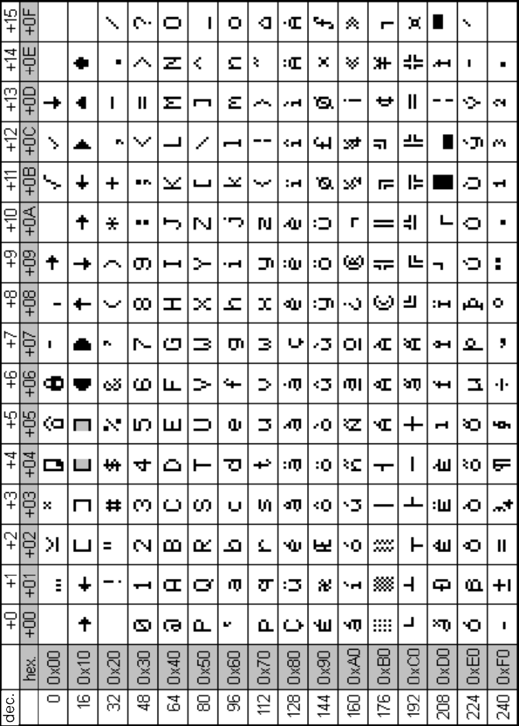
C-1
MOBY U – Manual for Configuration, Installation and Service
(4) J31069-D0139-U001-A2-7618
ASCII Table C

C-2 MOBY U – Manual for Configuration, Installation and Service
(4) J31069-D0139-U001-A2-7618
ASCII Table
Index-1
MOBY U – Manual for Configuration, Installation and Service
(4) J31069-D0139-U001-A2-7618
Index
Number
3RX9 802-0AA00, 6-4
6ES7 194-1AA00-0XA0, 6-4
6ES7 194-1FC00-0XA0, 6-4
6ES7 390-5AA00-0AA0, 6-19
6ES7 390-5BA00-0AA0, 6-19
6ES7 392-1AJ00-0AA0, 6-24
6GT2 000-0EF00, 4-9
6GT2 001-0EA10, 5-4
6GT2 002-0EB20, 6-4
6GT2 002-0HA00, 6-12, 6-19
6GT2 080-2AA10, 6-4, 6-12, 6-19, 7-3
6GT2 090-0A..., 3-21, 6-7
6GT2 090-0AN50, 3-28
6GT2 090-0AT12, 3-28
6GT2 090-0AT80, 3-28
6GT2 090-0BA00, 3-28
6GT2 090-0BC00, 6-4, 6-7
6GT2 090-0QA00, 4-12
6GT2 090-0QA00-ZA31, 4-12
6GT2 090-0QB00, 4-12
6GT2 091-0E..., 6-19, 6-24
6GT2 091-0EH20, 3-25
6GT2 091-0EH50, 3-25
6GT2 091-0EN10, 3-25
6GT2 091-0EN20, 3-25
6GT2 091-0EN50, 3-25
6GT2 091-1C..., 6-12
6GT2 091-1CH20, 3-24, 6-4, 6-7, 6-12, 6-19
6GT2 091-1CH50, 3-24
6GT2 091-1CN10, 3-24
6GT2 091-1CN20, 3-24
6GT2 091-1CN50, 3-24
6GT2 091-2CH20, 3-24
6GT2 091-2E..., 3-25, 6-19
6GT2 091-2EH20, 3-25
6GT2 091-2EH50, 3-25
6GT2 091-2EN10, 3-25
6GT2 091-2EN50, 3-25
6GT2 097-3AC40-0DA1, A-1
6GT2 097-3AC40-0DA2, A-1
6GT2 097-3AC60-0DA1, 6-4
6GT2 097-3AM00-0DA1, 6-4, 6-12, 6-19, A-1
6GT2 097-3AM00-0DA2, 6-4, 6-12, 6-19, A-1
6GT2 390-1AB00, 3-28
6GT2 491-1HH50, 7-4
6GT2 494-0AA00, 3-22, 7-4
6GT2 500-5JK10, 4-12
6GT2 590-0QA00, 4-12
6SE7 198-8FA01-8AA0, 6-13
A
ASM 452
Dimensions, 6-8
Ordering data, 6-4
Pin allocations, 6-9
PROFIBUS address and terminating resist-
ance, 6-10
PROFIBUS configuration, 6-6
SLG connection technology, 6-7
Technical data, 6-5
ASM 473
Configuration, 6-14
Dimensions, 6-17
Hardware configuration, 6-15
Ordering data, 6-12
Pin allocations, 6-16
Setup and function, 6-11
SLG connection technology, 6-15
Technical data, 6-12
ASM 475
Ordering data, 6-19
Setup and functions, 6-18
Technical data, 6-20
B
Basic EMC rules, 3-18
C
Cable configuration, 3-21

Index-2 MOBY U – Manual for Configuration, Installation and Service
(4) J31069-D0139-U001-A2-7618
Cables, Shielding, 3-16
E
EMC guidelines, Avoiding interference sources,
3-14
Equipotential bonding, 3-15
Extra power pack for SLG, 3-22
L
LEDs for MOBY, 6-16
LEDs for PROFIBUS-DP, 6-16
M
MDS U313
Field data, 4-7
Ordering data, 4-6
Technical data, 4-6
MDS U524
Field data, 4-10
Ordering data, 4-9
Technical data, 4-9
MDS U589
Field data, 4-14
Ordering data, 4-12
Technical data, 4-13
MOBY Software, 7-2
Ordering data, 7-3
MOBY wide-range power pack
Dimensions, 7-6
Ordering data, 7-4
Plug allocation of 24 V output, 7-6
Technical data, 7-5
O
Ordering data, Descriptions, A-1
P
Plug connector allocations, 3-22
S
Shielding concept, 3-20
SLG U92
Field data, 5-7
Ordering data, 5-4
Technical data, 5-5
T
Transmission window, 3-3
Index
To:
Siemens AG
A&D SE ES4
Postfach 2355
D-90713 Fuerth
Sender:
Your name:
_______________________________
Your position:
______________________________
Your company:
_______________________________
Street: _______________________________
City: _______________________________
Telephone:______________________________
Please check your branch of industry.
❒Automotive industry
❒Chemicals industry
❒Electro industry
❒Foodstuffs
❒Control technology
❒Mechanical engineering
❒Petrochemicals
❒Pharmaceutical industry
❒Plastics
❒Paper
❒Textiles
❒Transportation
❒Other _____________

If you have experienced concrete problems, please explain here.
_____________________________________
_____________________________________
_____________________________________
_____________________________________
_____________________________________
_____________________________________
_____________________________________
_____________________________________
_____________________________________
_____________________________________
_____________________________________
_____________________________________
Remarks/suggestions
Your ideas and suggestions help us to improve the quality and usefulness of our documenta-
tion. Please fill out this questionnaire and return it to Siemens.
Title of the manual:____________________________
Order number of the manual: _______________________
Answer the following questions with your personal opinion (1 = good to 5 = poor).
1. Does this manual satisfy your requirements?
2. Is the information easy to find?
3. Is the information easy to understand?
4. Are there enough technical details to satisfy your requirements?
5. What is your opinion of the figures and tables?