Siemens MOBYU-SLGU92-0 Write-Read-Station for identification system User Manual J31069 D0139 U001 A2 7618
Siemens AG Write-Read-Station for identification system J31069 D0139 U001 A2 7618
UserManual.wiki
>
Siemens
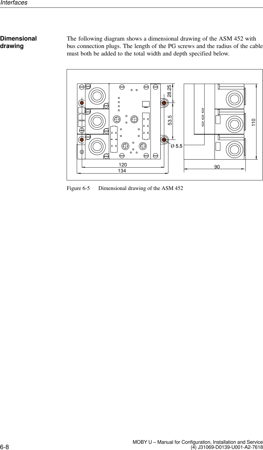
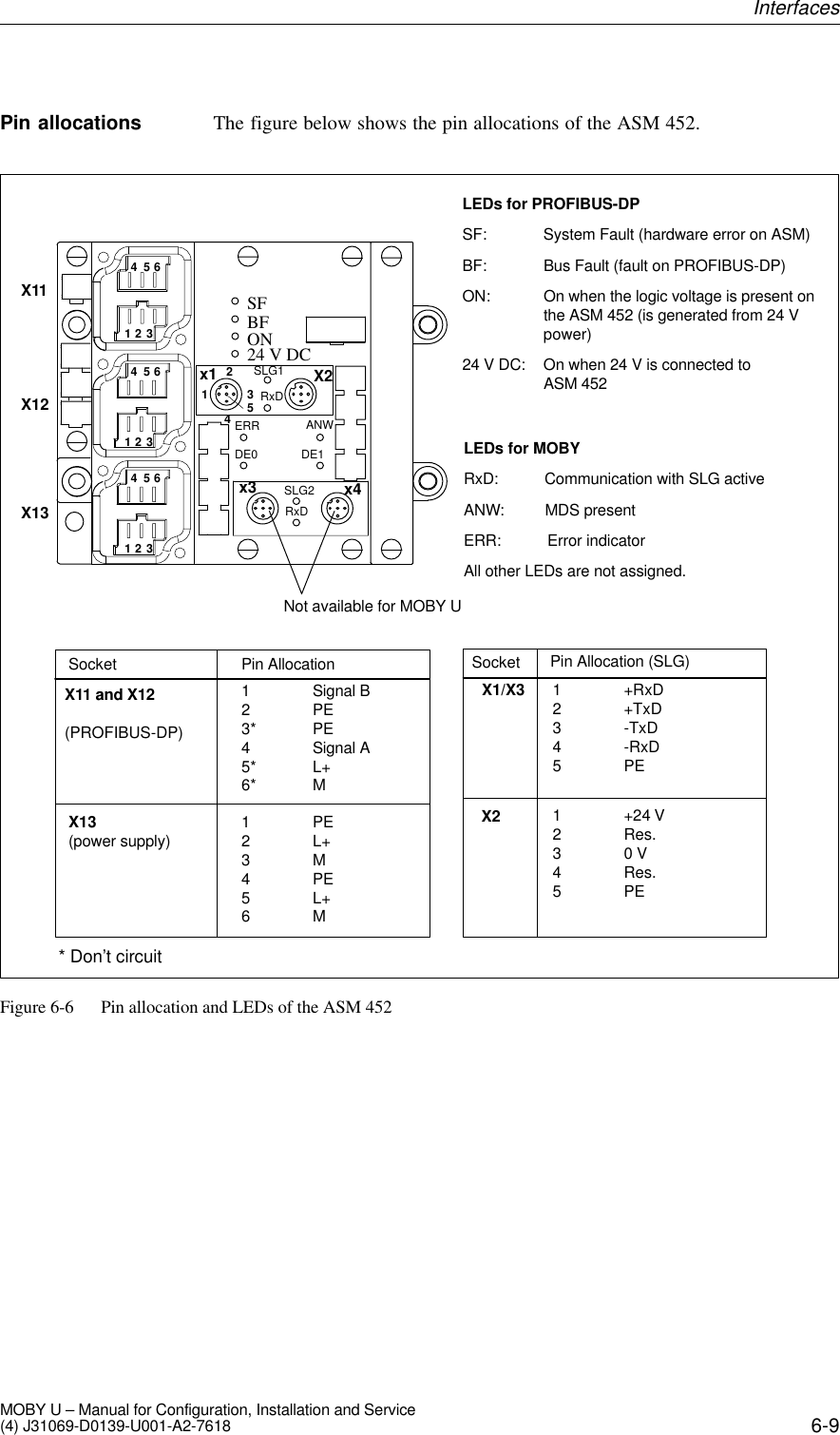
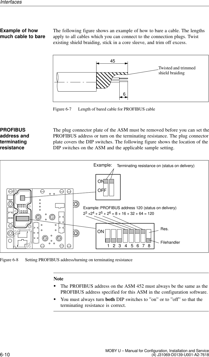
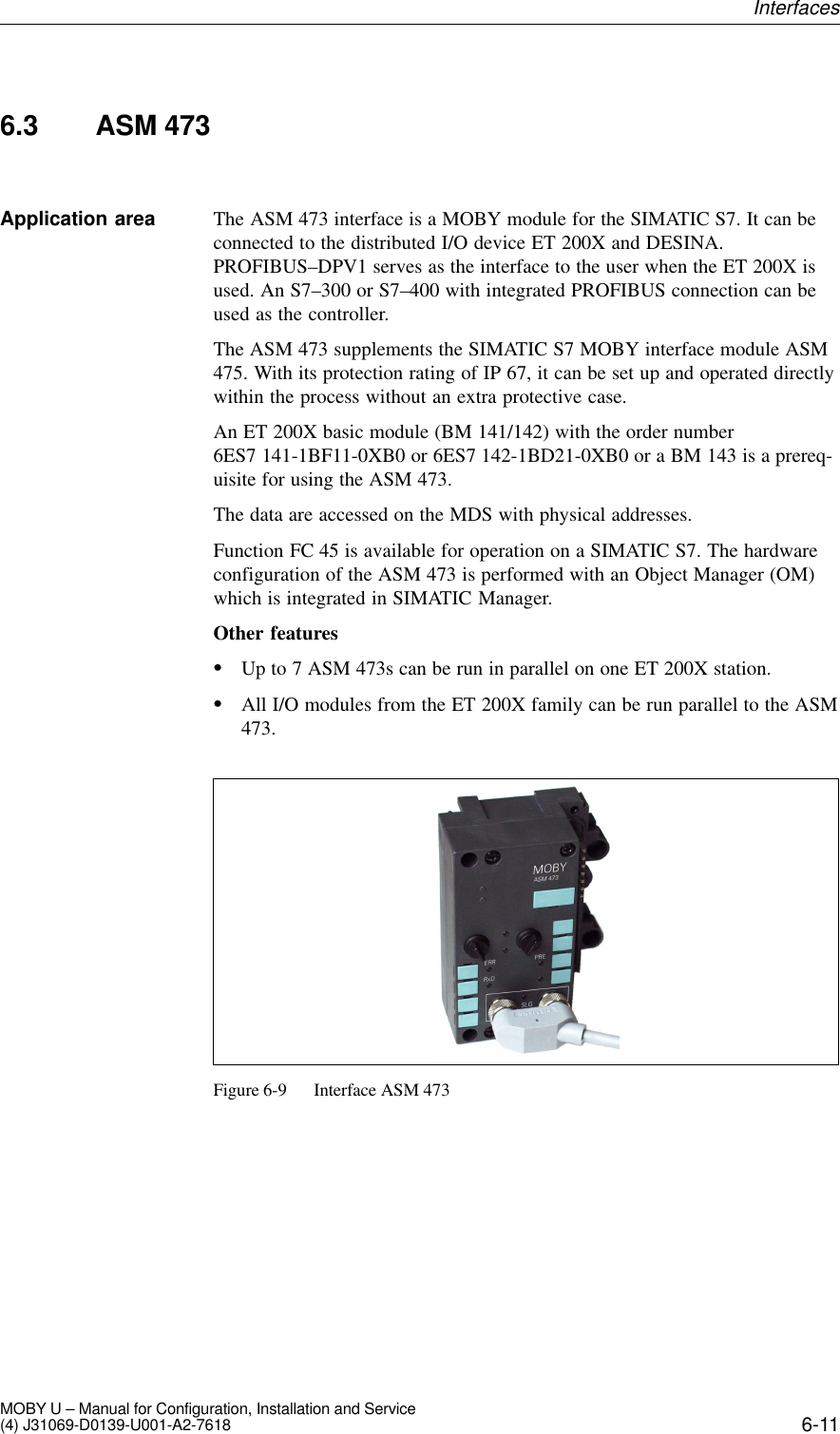
>
MOBYU-SLGU92-0 User Manual
>
user manual
Contents
1.
user manual
2.
data sheet
3.
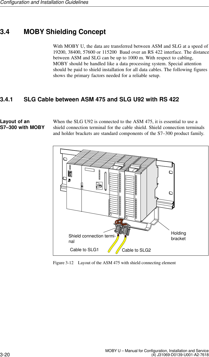
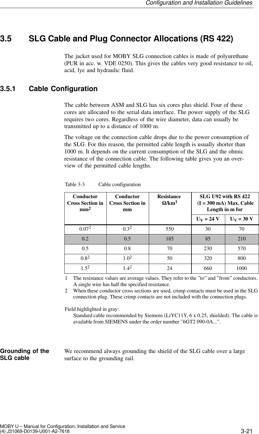
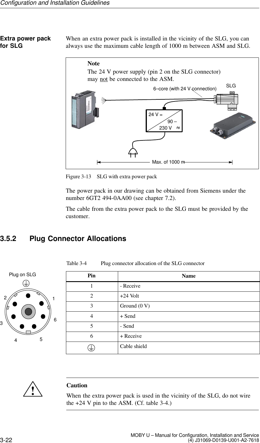
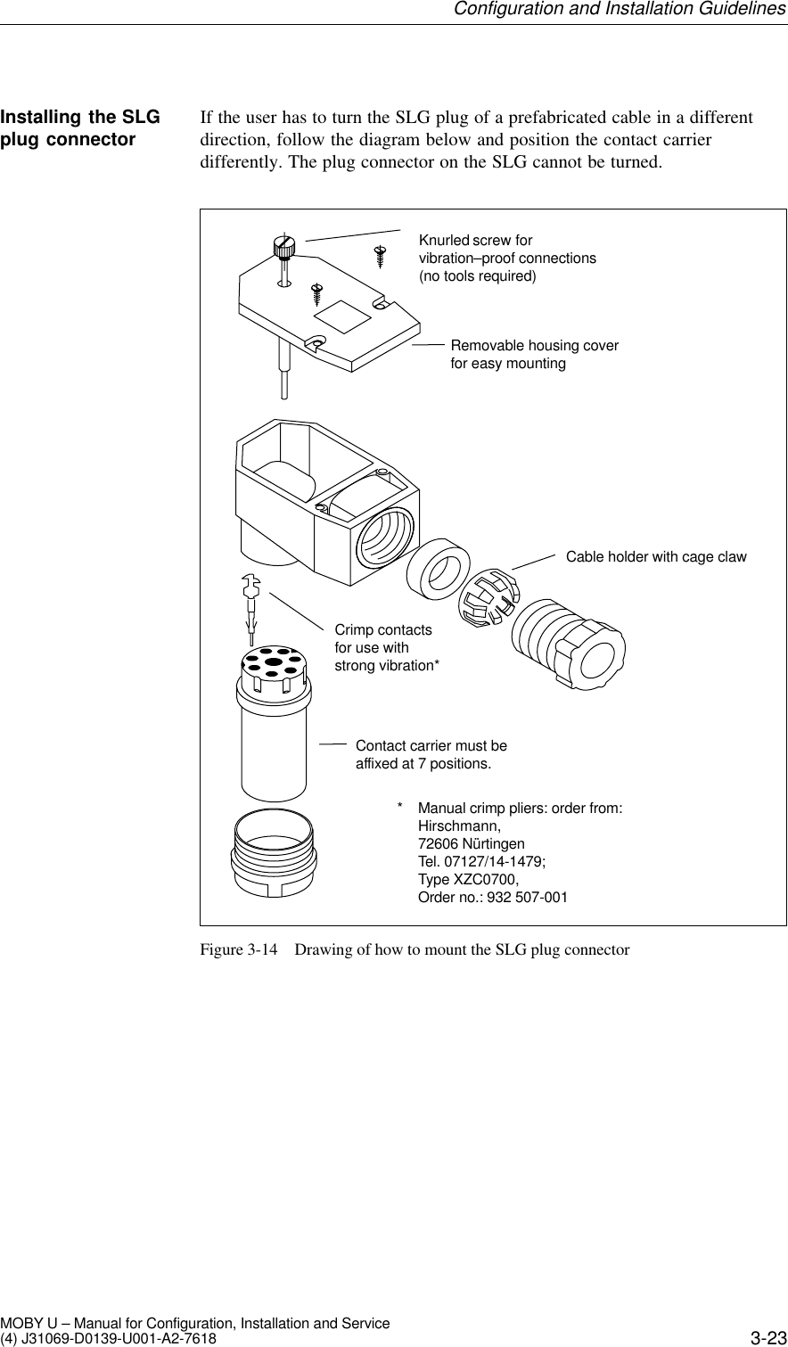
Additional information to user manual
4.
product information sheet
user manual
Navigation menu
Upload a User Manual
Namespaces
Wiki Guide
HTML
PDF
Info
Views
User Manual
Discussion / Help
Navigation
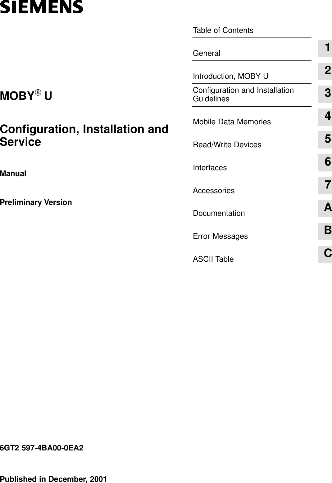

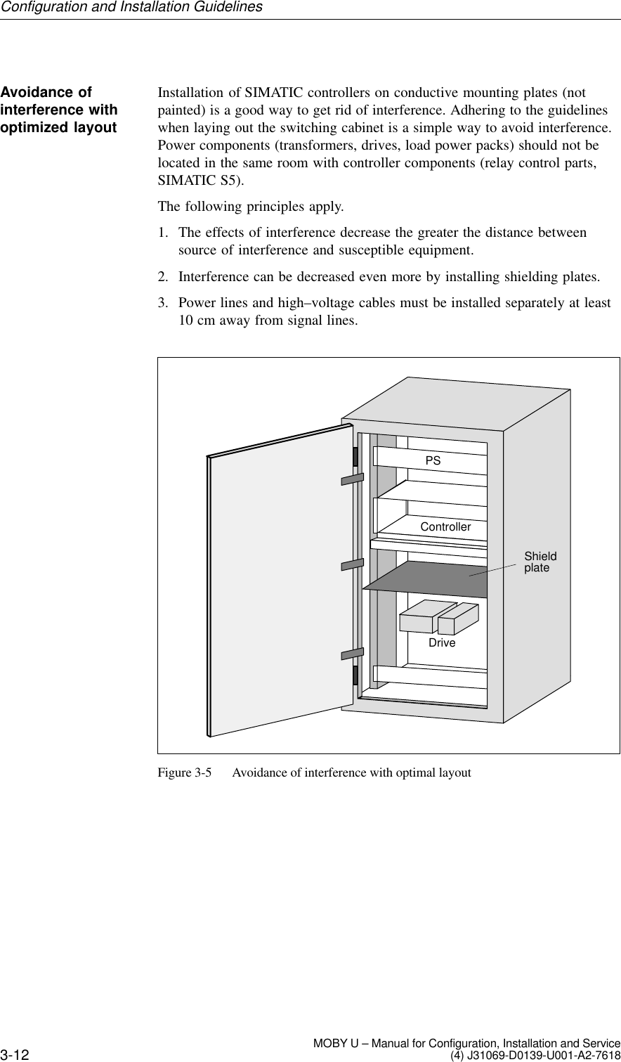
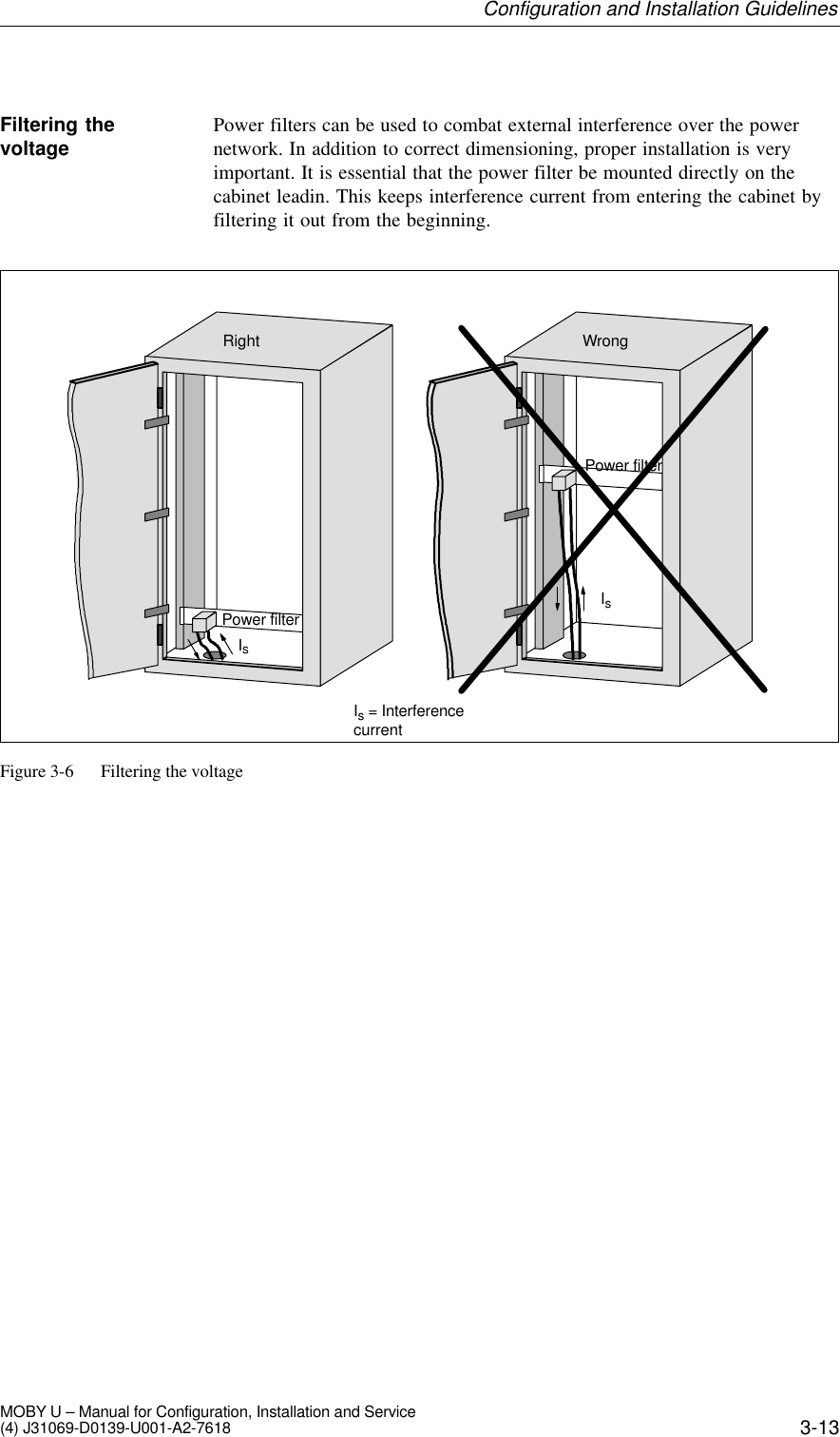
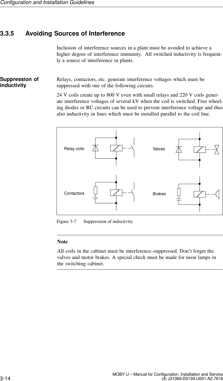
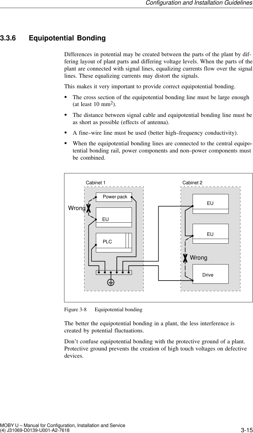


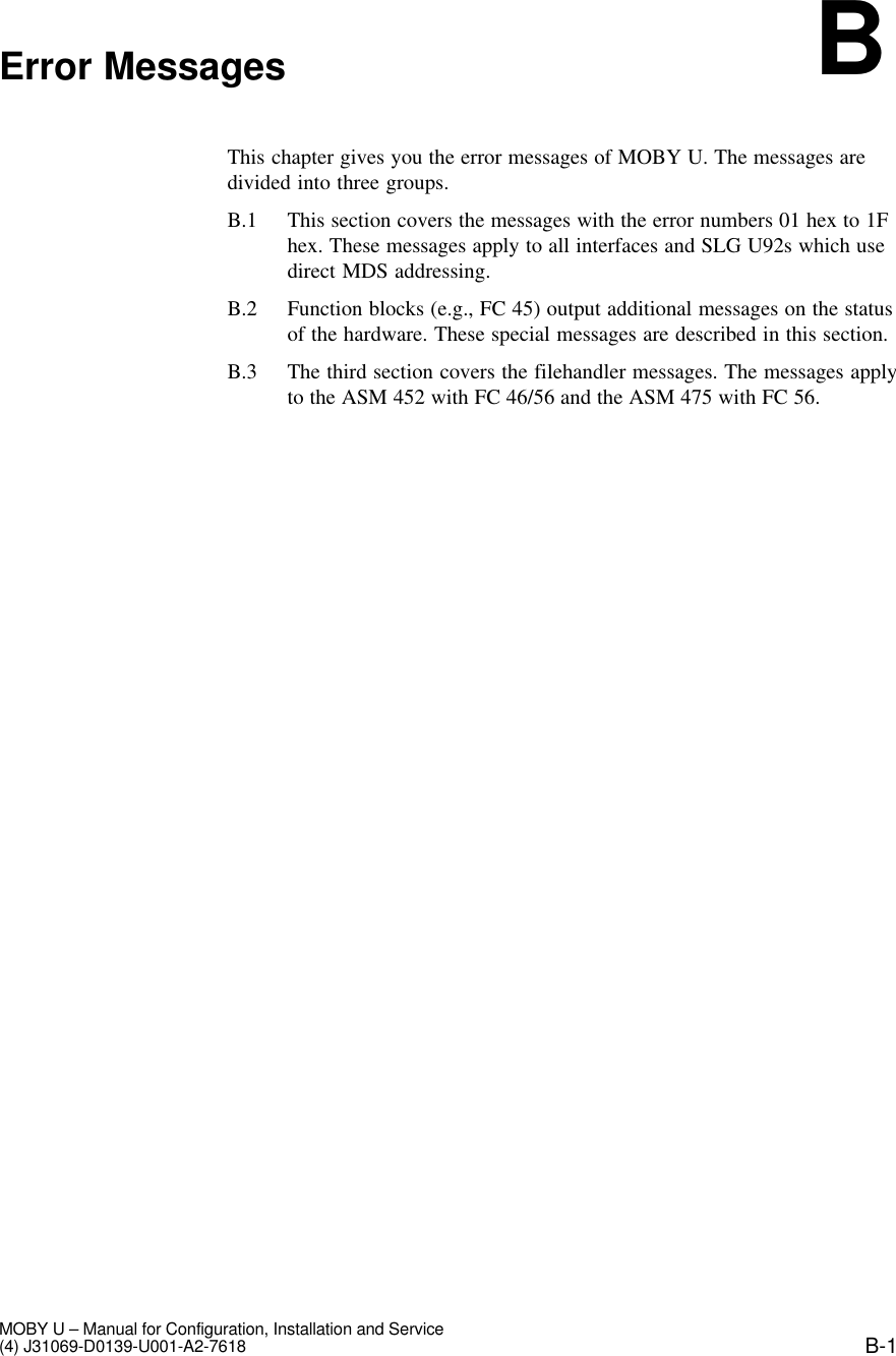
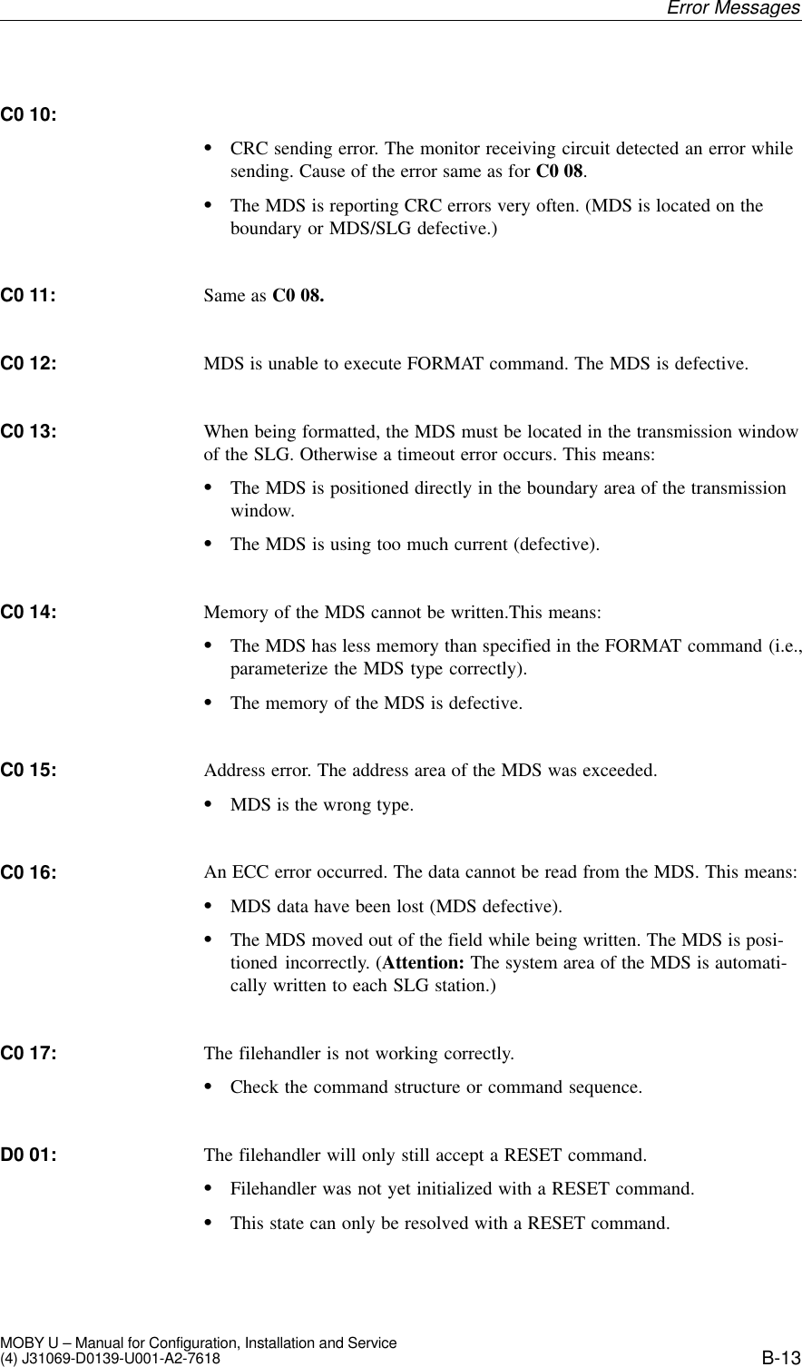
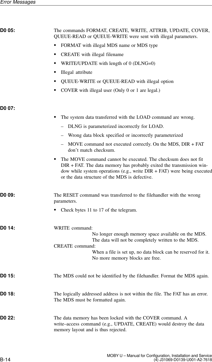
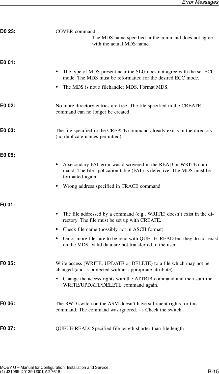
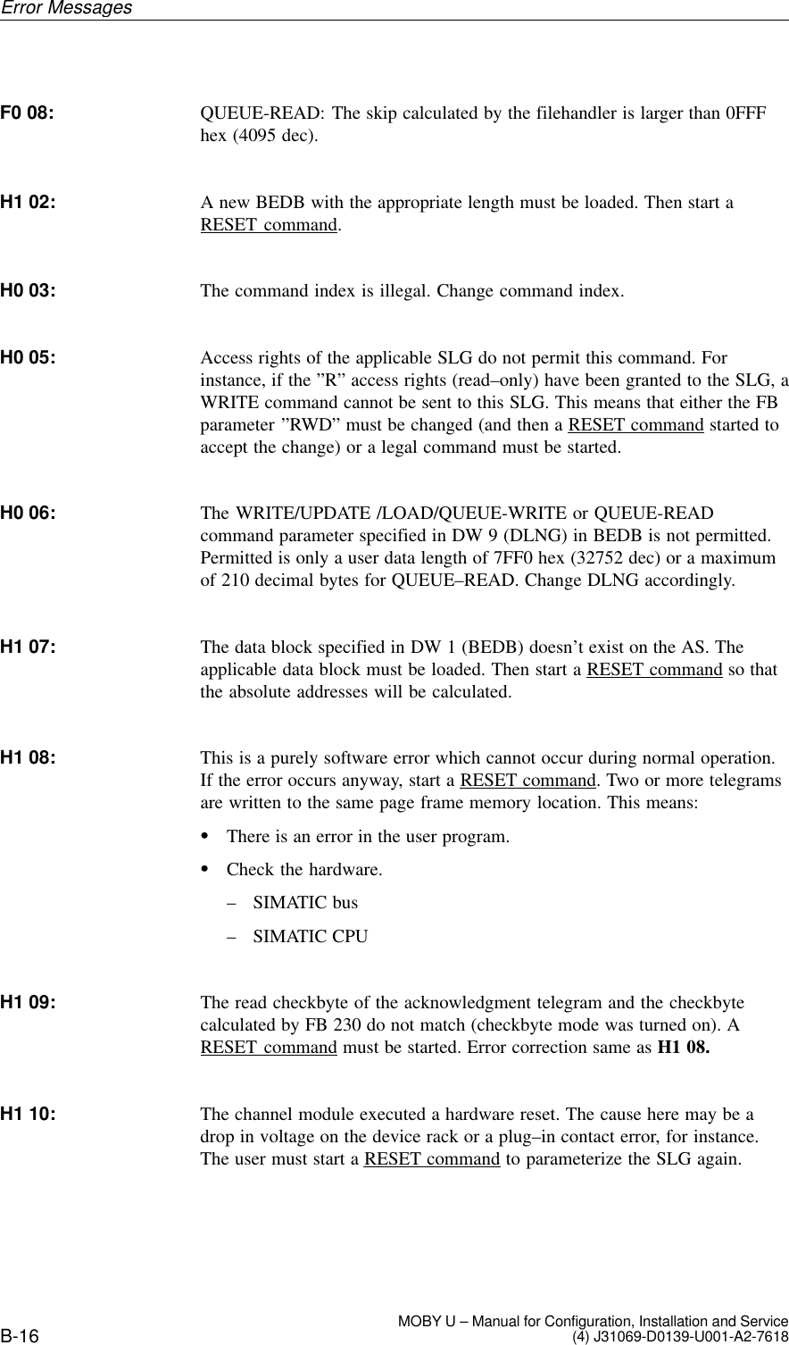
![5-6 MOBY U – Manual for Configuration, Installation and Service(4) J31069-D0139-U001-A2-7618Table 5-2 Technical data of the SLG U92ASM/PC Interface 6–pin SLG plug in acc. w. EN 175201-804RS 232 or RS 422 (SLG U92 version)Transmission speedTransmission protocolLine length, SLG - ASMLine length, SLG - PCAutomatic baud rate recognition, 19.2 to 115.2KBaud (depends on ASM/PC and/or line length)3964 RMax. of 1000 m (RS 422; shielded)Max. of 30 m (RS 232; shielded)Service interface 11-pin plug in acc. w. EN 175201-804Interface for serviceTransmission speedLine length, SLG - PCTransmission protocol2 DIs for proximity switchDI 1/DI 2DI 1 (or DI 2)Line length, SLG - proximityswitchInterface for SLG synchroniza-tionLine length, SLG - SLGRS 23219.2 KBaud Max. of 30 mTerminal, ASCII charactersProximity switch for trigger antenna field, on/offProximity switch for antenna field duration, onMax. of 50 mMax. of 30 mIndicator elements 2 LEDsHousingDimensions [L x W x H]ColorMaterial290 x 135 x 42 without plugAnthracitePlastic, PA 12 GF 25Mounting 4 M6screwsTightening moment (at roomtemperature)v 2 NmShock, vibration in acc. w. DINEN721-3-7, class 7 M330 g/1.5 gMTBF (at +40 °C) 2 x 10⁶ hoursProtection rating in acc. w. EN60529 IP 65Ambient temperatureOperationTransportation and storage–25 to +70 °C–40 to +85 °CWeight, approx. 900 gRead/Write Devices](https://usermanual.wiki/Siemens/MOBYU-SLGU92-0.user-manual/User-Guide-222601-Page-66.png)