Siemens RF340R Inductive Tag Reader User Manual RFID Systeme SIMATIC RF300
Siemens AG Inductive Tag Reader RFID Systeme SIMATIC RF300
UserManual.wiki
>
Siemens
>
RF340R User Manual
>
Manual Part 3
Contents
1.
Manual Part 1
2.
Manual Part 2
3.
Manual Part 3
Manual Part 3
Navigation menu
Upload a User Manual
Namespaces
Wiki Guide
HTML
PDF
Info
Views
User Manual
Discussion / Help
Navigation
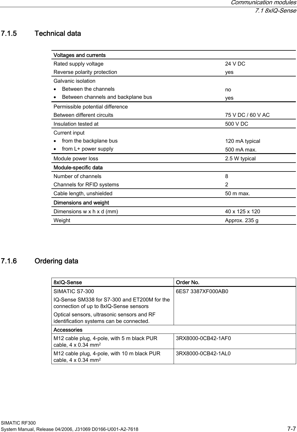

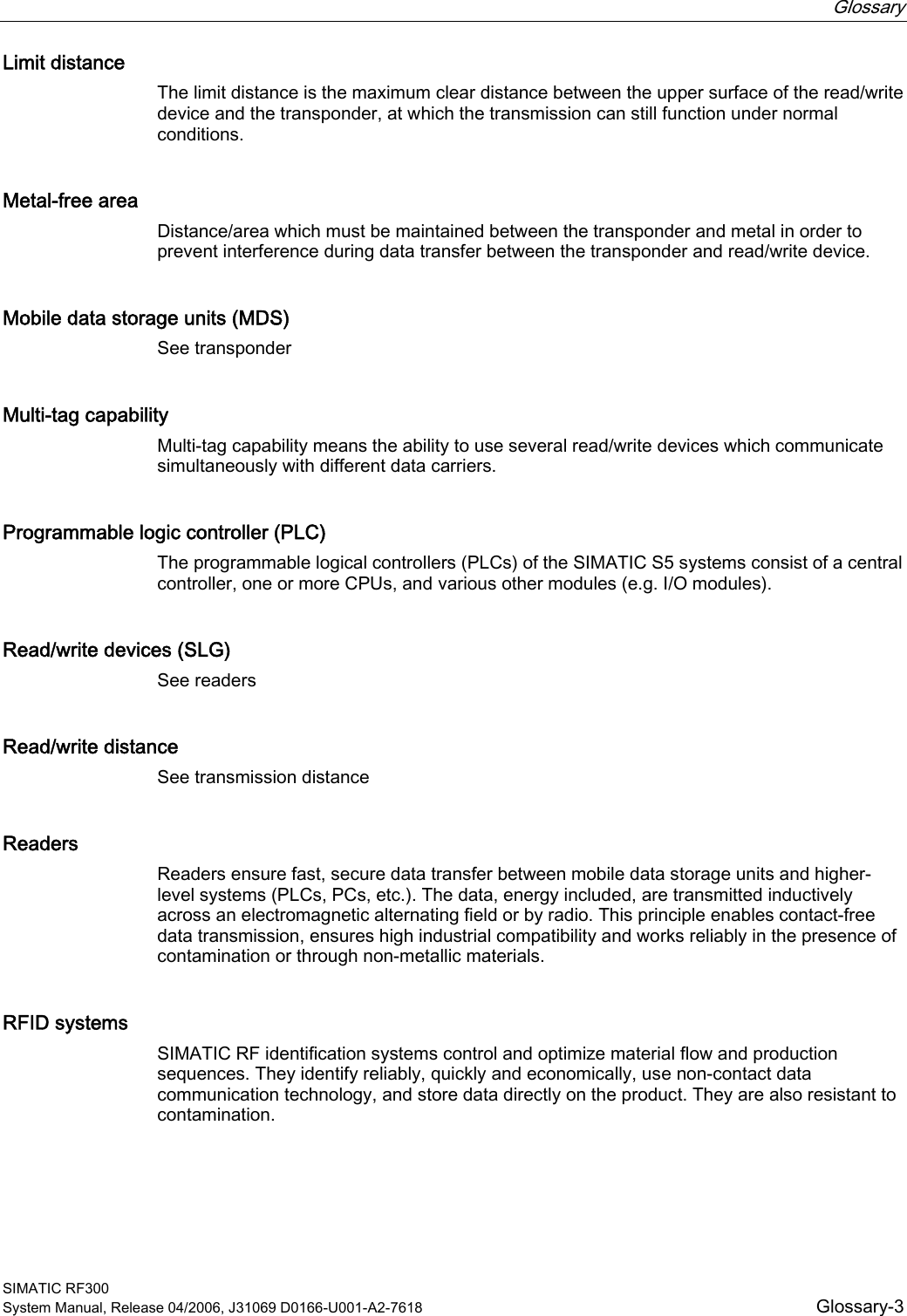
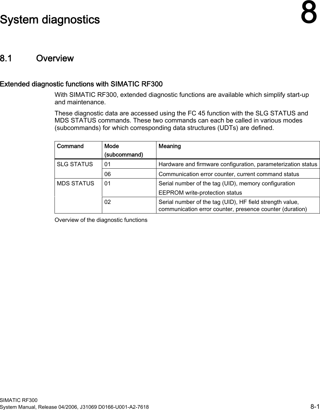
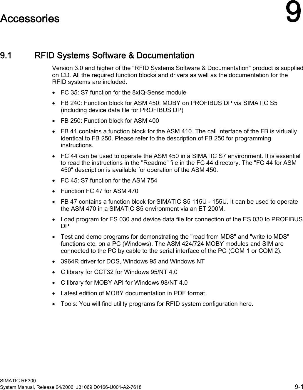
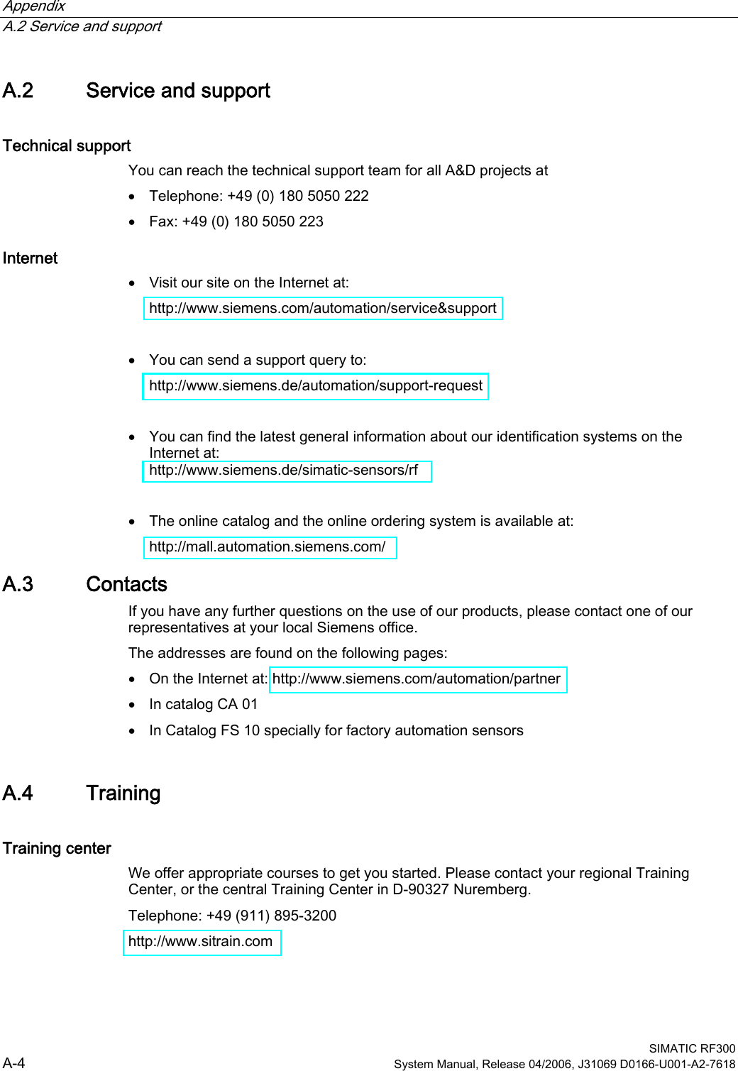
![Communication modules 7.4 ASM 473 SIMATIC RF300 7-36 System Manual, Release 04/2006, J31069 D0166-U001-A2-7618 7.4.2 Pin assignment and display elements Pin assignments The figure below illustrates the pin assignment for the read/write device and the display elements. 2))+]+]2))21+]+]+]2));;21SHUP2))21 5[' 7[' 7[' 5[' 3( 9 QF 9 QF 3((5535([IODVKHYHU\V6RFNHW 3LQDVVLJQPHQWUHDGHU/('VIRU352),%86'3*HQHUDOLQGLFDWRUV6)%)219'&DUHORFDWHGRQWKHEDVLFPRGXOHRIWKH(7;/('VIRU02%<5[' 5HDGHUDFWLYHZLWKFRPPDQG35( ,QGLFDWHVWKHSUHVHQFHRIDWUDQVSRQGHU(55 (UURULQGLFDWHGE\IODVKLQJVHTXHQFH7KHIROORZLQJ$60VWDWHVDUHDOVRLQGLFDWHGZLWKWKH/('V35(DQG(55'HVFULSWLRQ&DXVHV5HPHG\+DUGZDUHLVGHIHFWLYH5$0IODVK&KDUJHULVGHIHFWLYHFDQRQO\EHUHSDLUHGLQWKHIDFWRU\)LUPZDUHORDGLQJLVDFWLYHRUQRILUPZDUHGHWHFWHGൺ/RDGILUPZDUHൺ$60PXVWQRWEHVZLWFKHGRIIXQWLOORDGHG)LUPZDUHORDGLQJWHUPLQDWHGZLWKHUURUVൺ5HVWDUWUHTXLUHGൺ/RDGILUPZDUHDJDLQൺ&KHFNXSGDWHILOHV2SHUDWLQJV\VWHPHUURUൺ6ZLWFK$60RU(7;EDVHVWDWLRQ2))21$60KDVERRWHGDQGLVZDLWLQJIRUD5(6(7LQLWBUXQIURPWKHXVHU Figure 7-26 Interfaces and indicators of the ASM 473 for RF300](https://usermanual.wiki/Siemens/RF340R.Manual-Part-3/User-Guide-668536-Page-30.png)

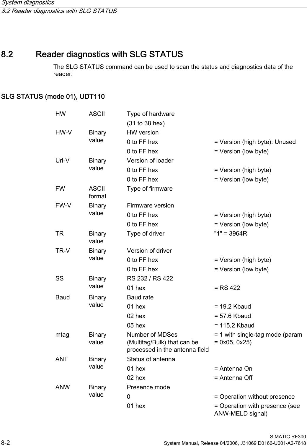
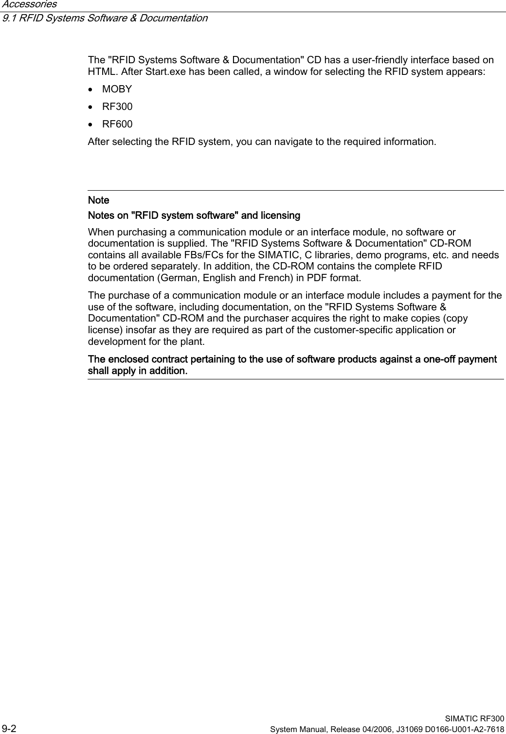

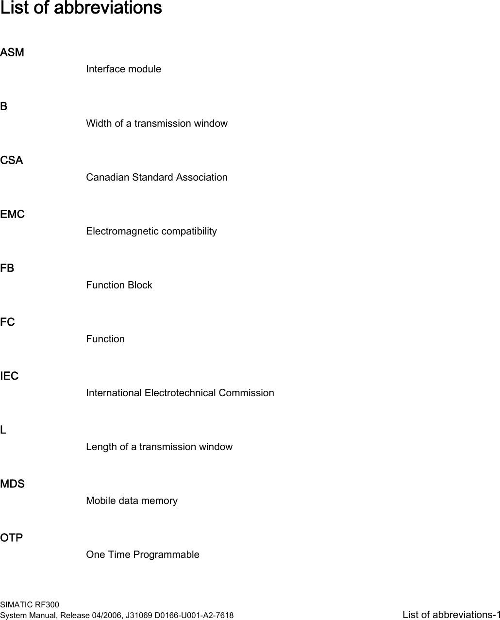
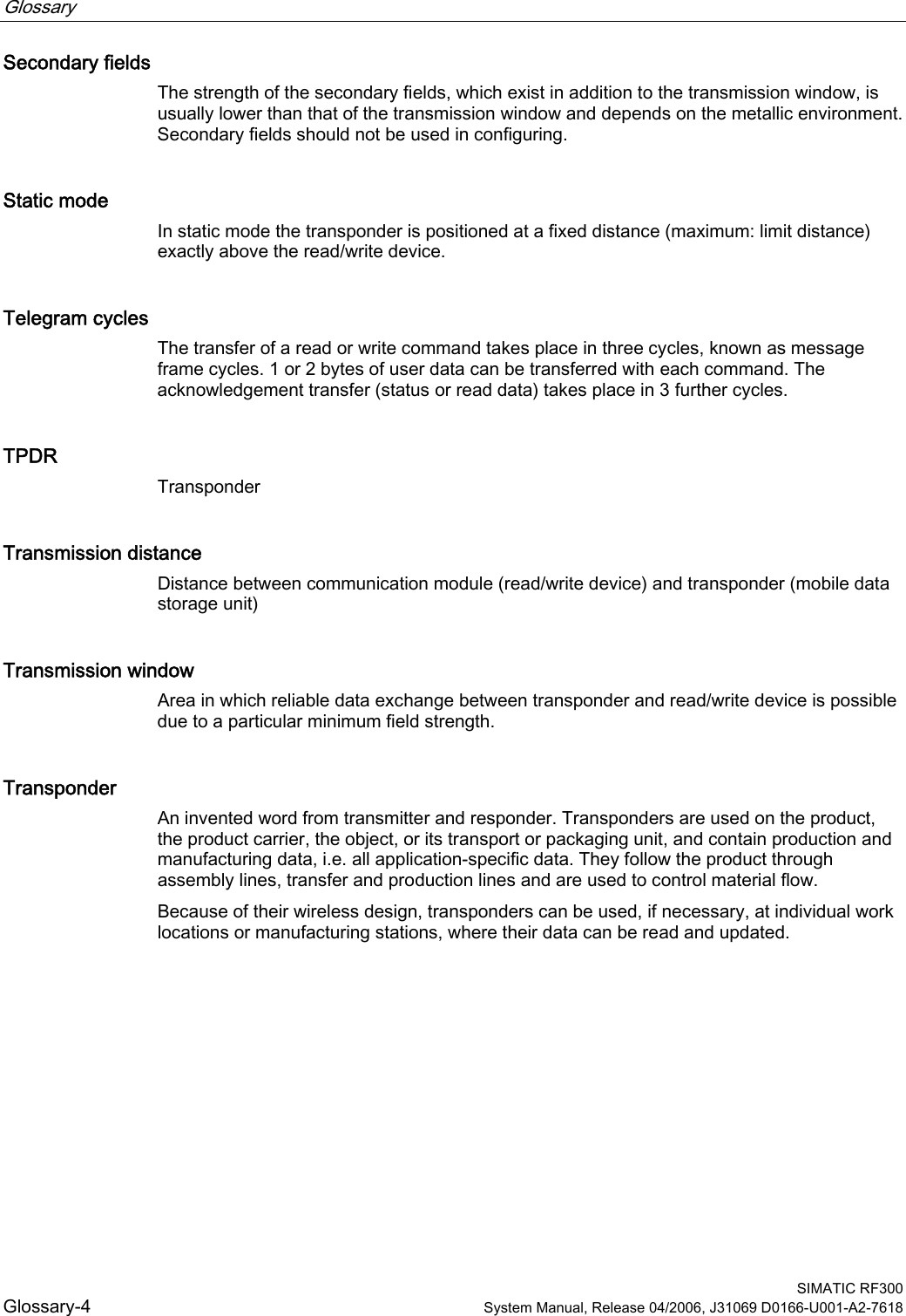
![List of abbreviations SIMATIC RF300 List of abbreviations-2 System Manual, Release 04/2006, J31069 D0166-U001-A2-7618 RFID Radio Frequency Identification Devices Sa Operating distance between MDS and SLG Sg Limit distance SLG Read/write device SP Intersection of the axes of symmetry of the MDS Tag See transponder TPDR Transponder UHF Ultra High Frequency UID Unique Identification. A serial number which identifies the transponder uniquely. UL Underwriter Laboratories, USA VDE Verband Deutscher Elektrotechniker [Association of German Electrical Engineers] XPDR Transponder](https://usermanual.wiki/Siemens/RF340R.Manual-Part-3/User-Guide-668536-Page-58.png)