Siemens RF340R02 RFID Reader 13.56 MHz User Manual SIMATIC RF300
Siemens AG RFID Reader 13.56 MHz SIMATIC RF300
UserManual.wiki
>
Siemens
>
RF340R02 User Manual
>
User Manual part 2
Contents
1.
User Manual part 2
2.
User Manual part 1
3.
User Manual part 3
4.
Users manual 1 of 3
5.
Users manual 2 of 3
6.
User manual 3 of 3
User Manual part 2
Navigation menu
Upload a User Manual
Namespaces
Wiki Guide
HTML
PDF
Info
Views
User Manual
Discussion / Help
Navigation
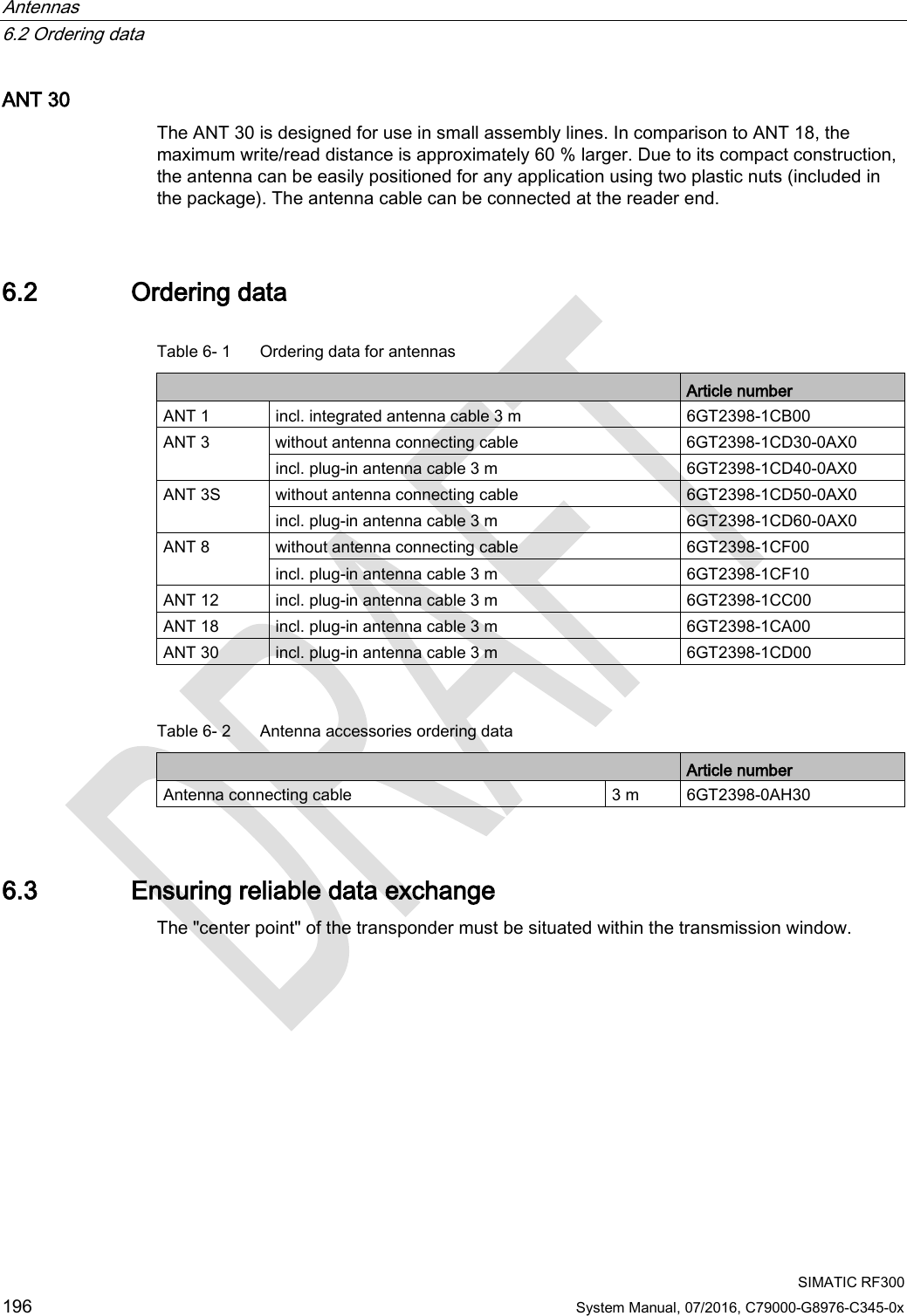
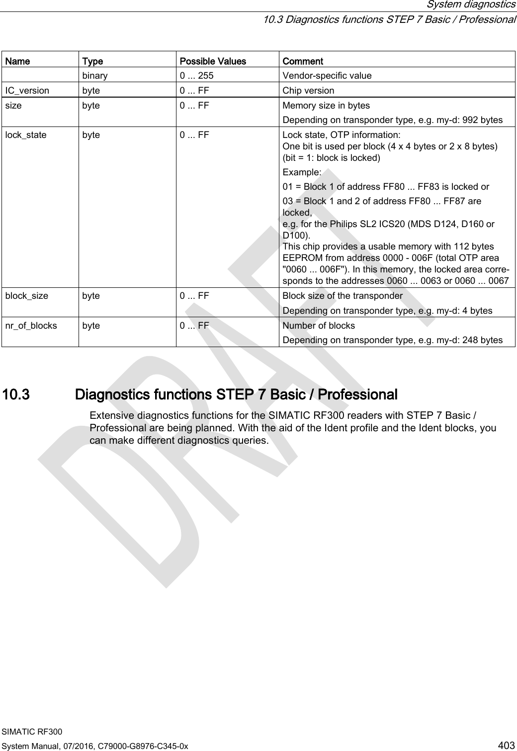
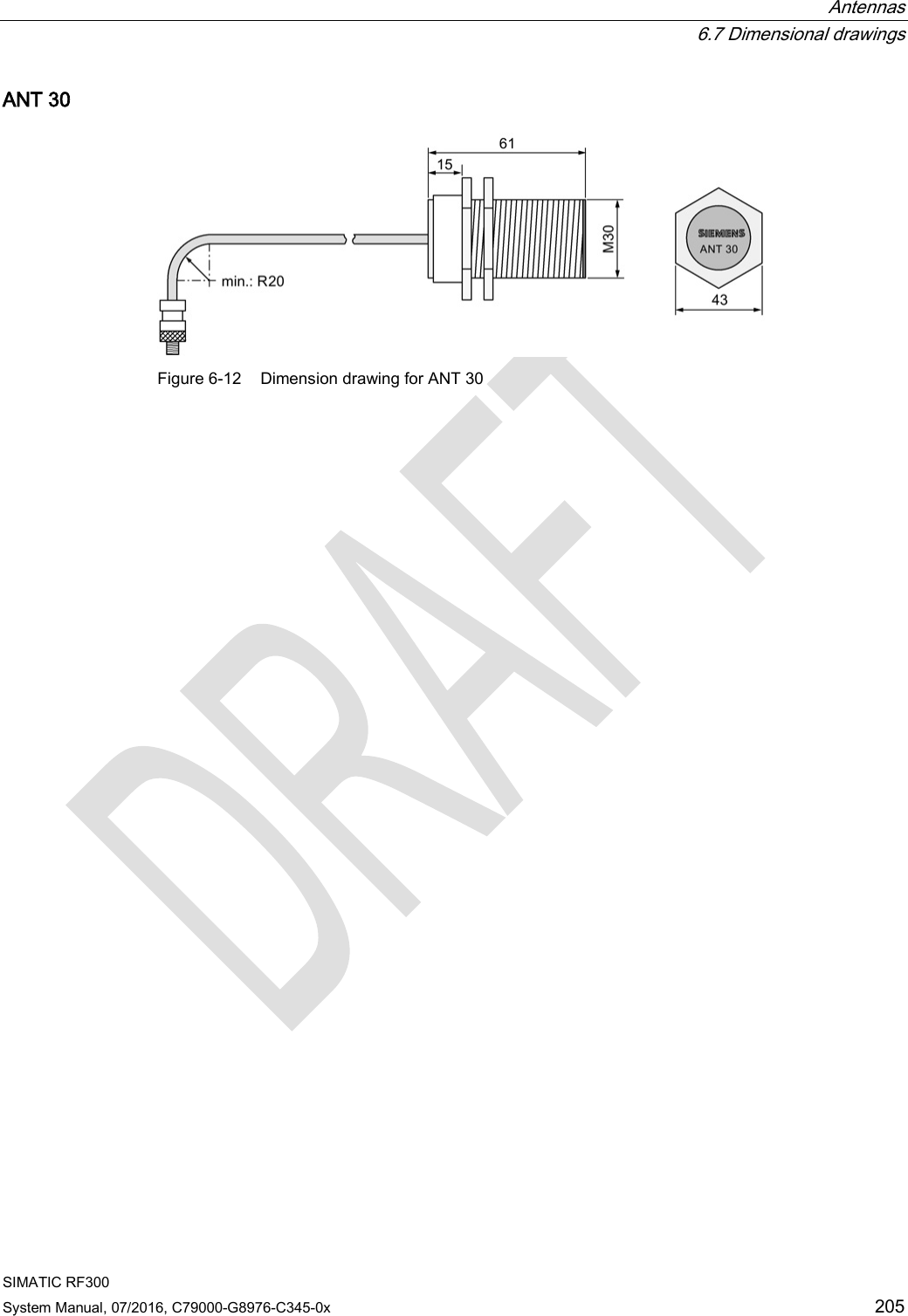
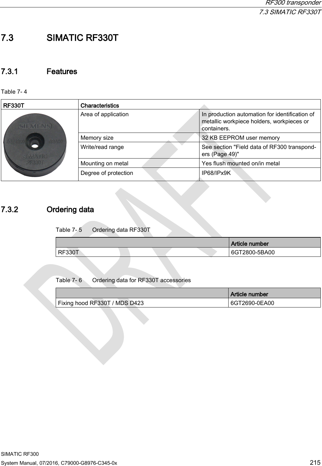
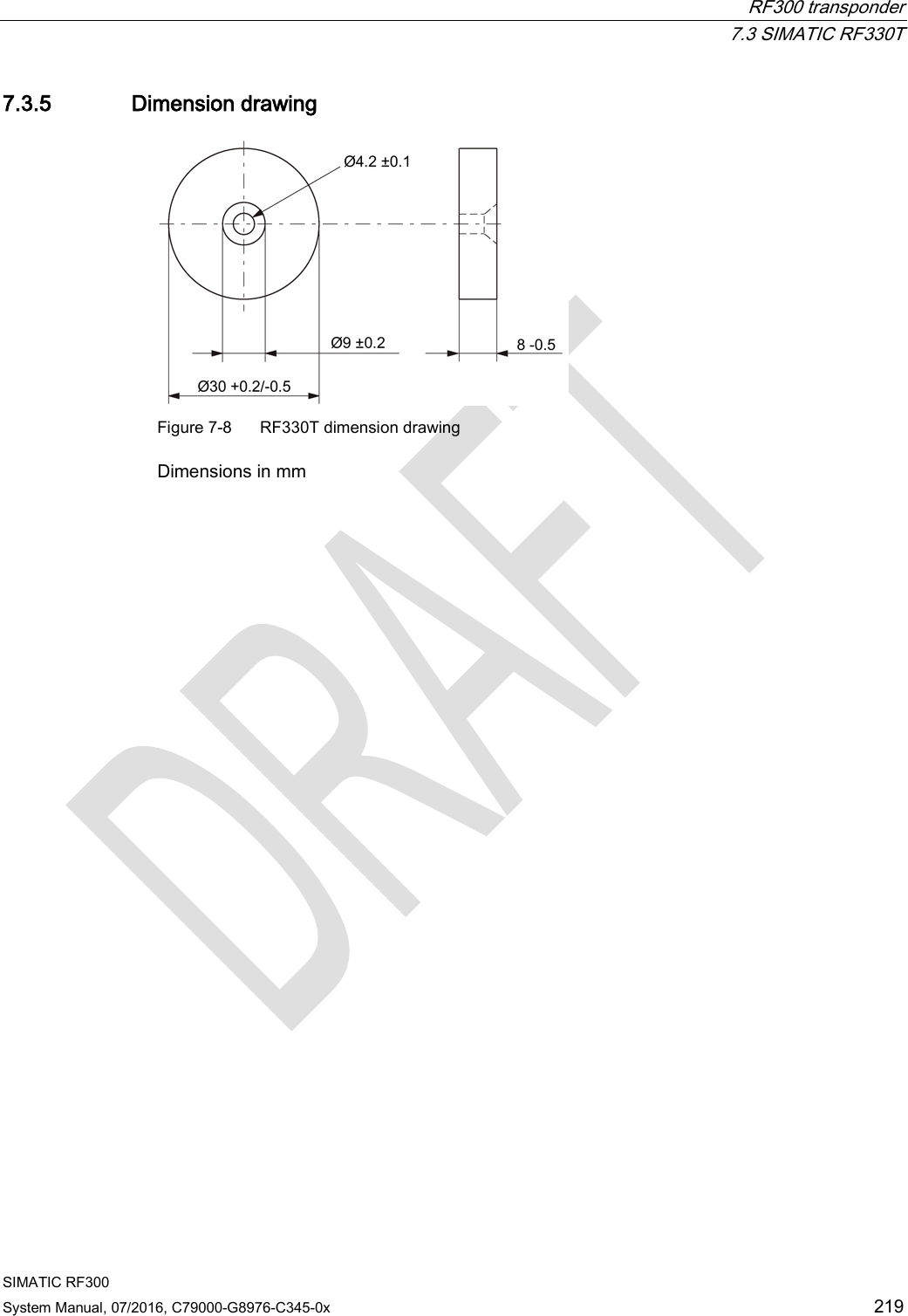
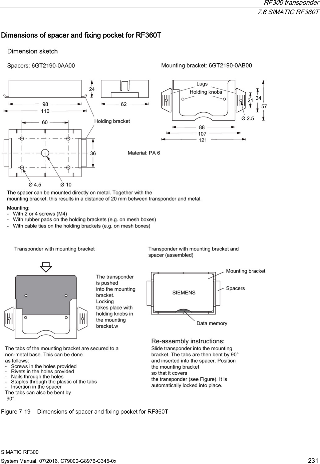
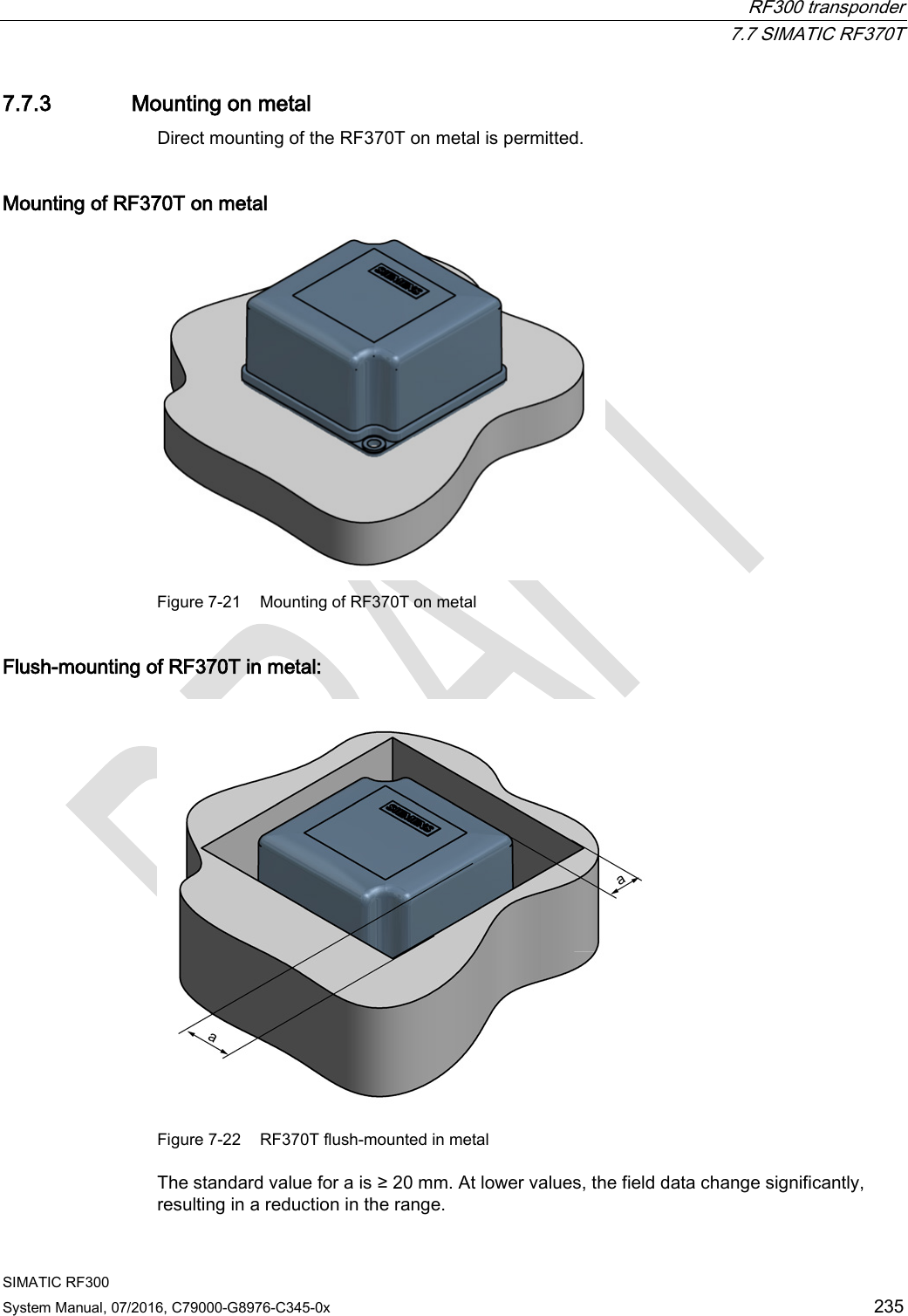
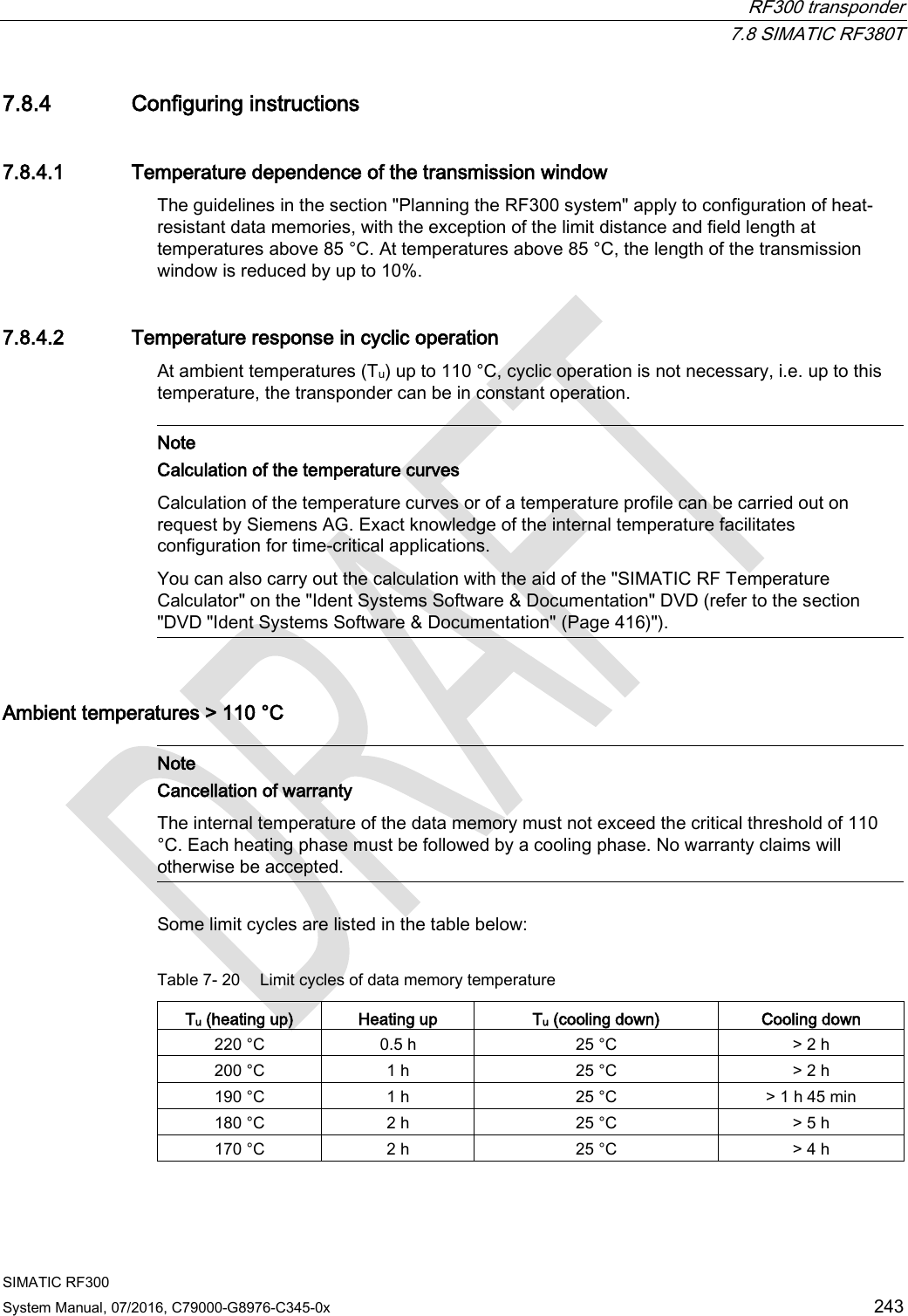
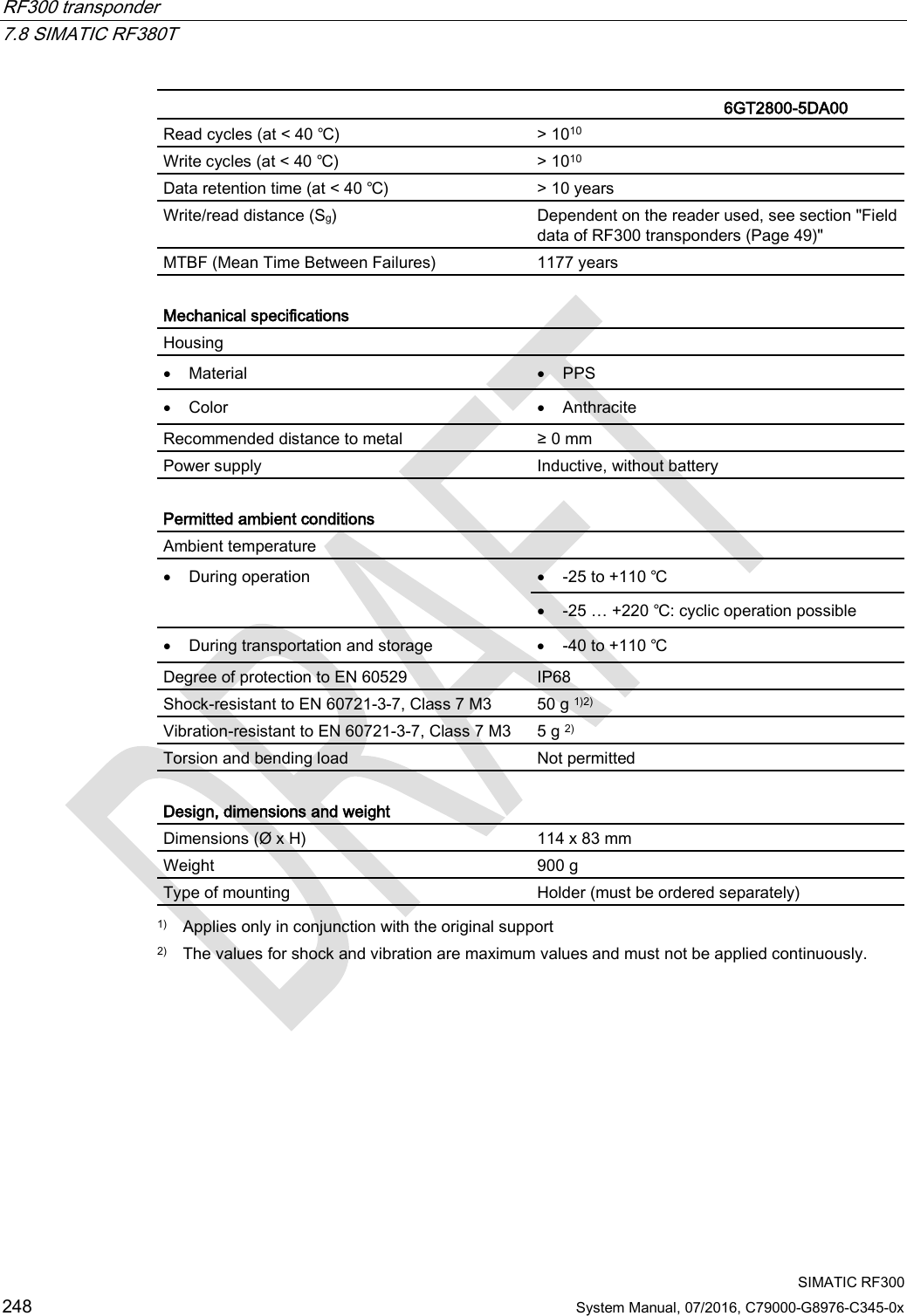
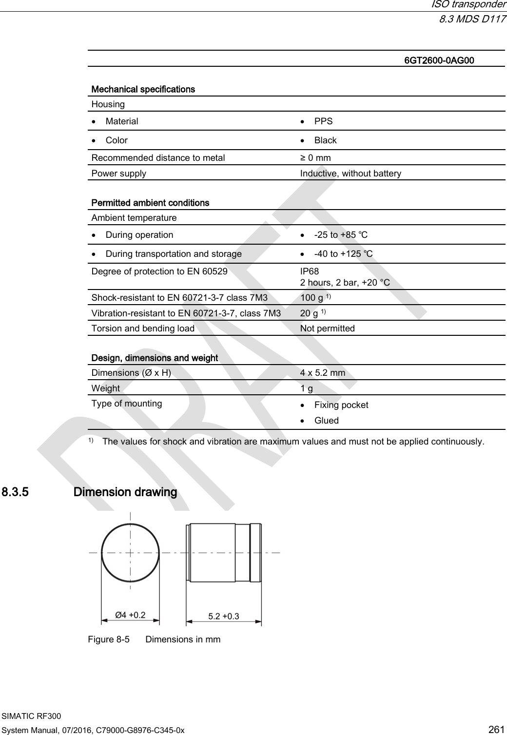
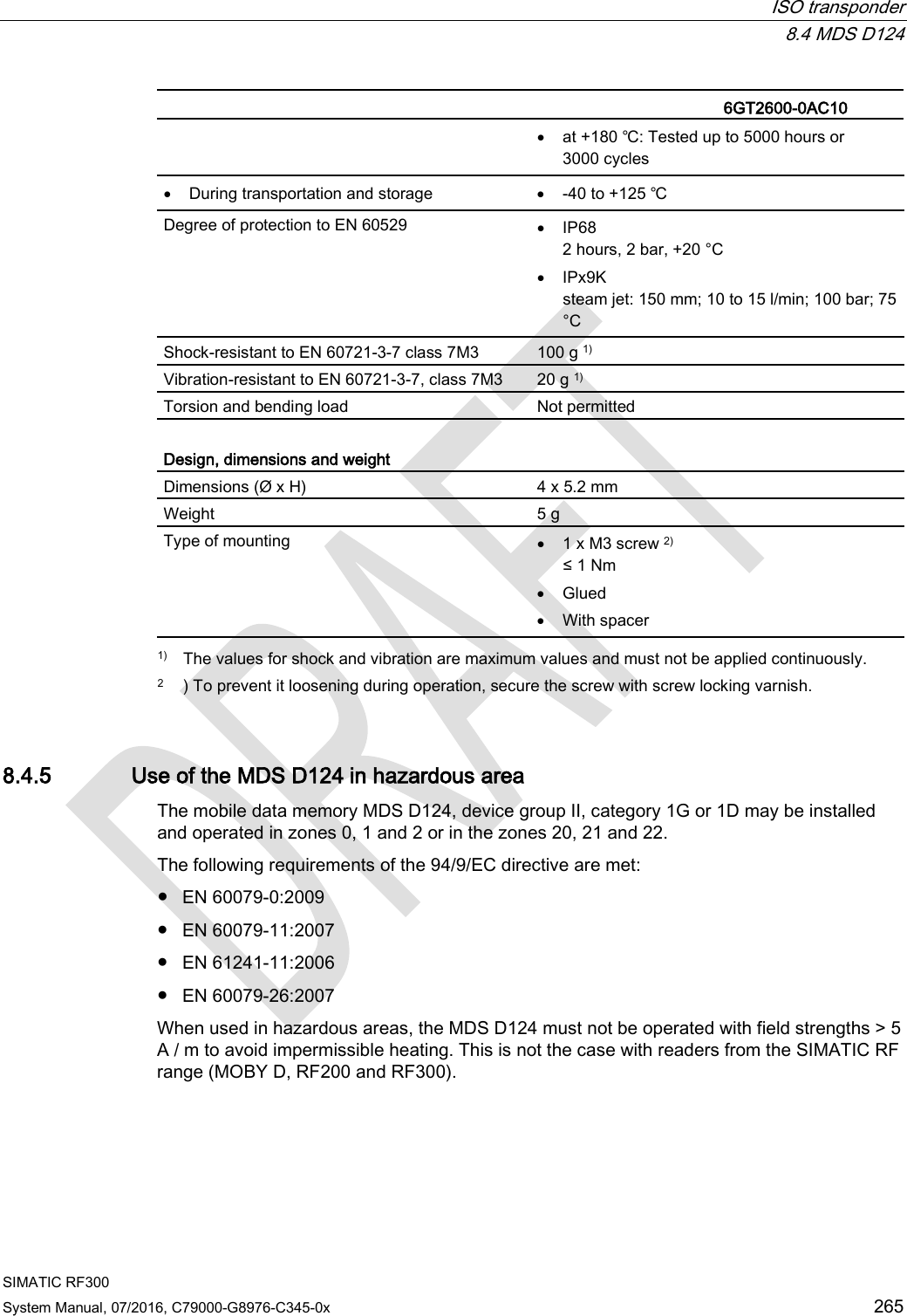
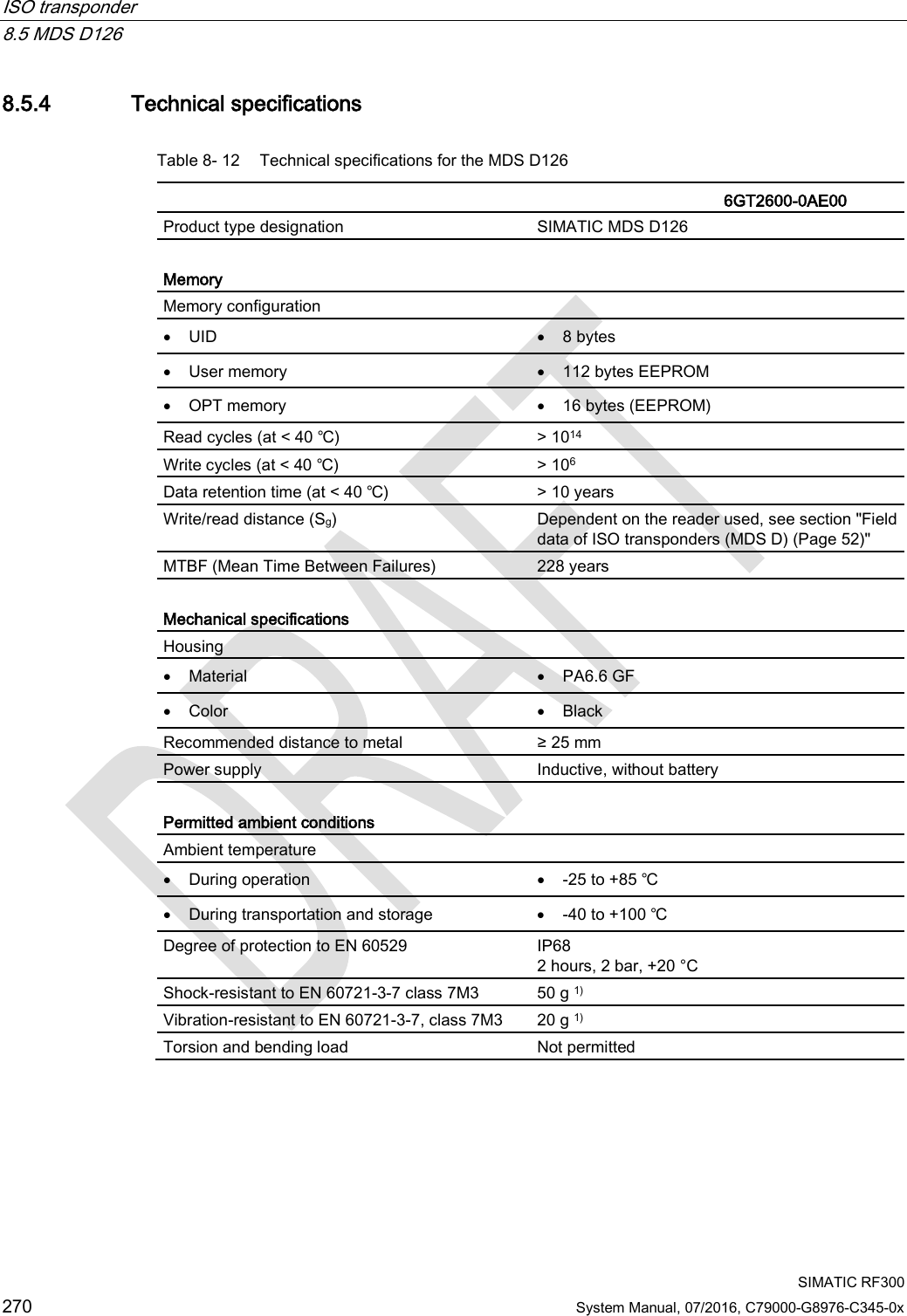
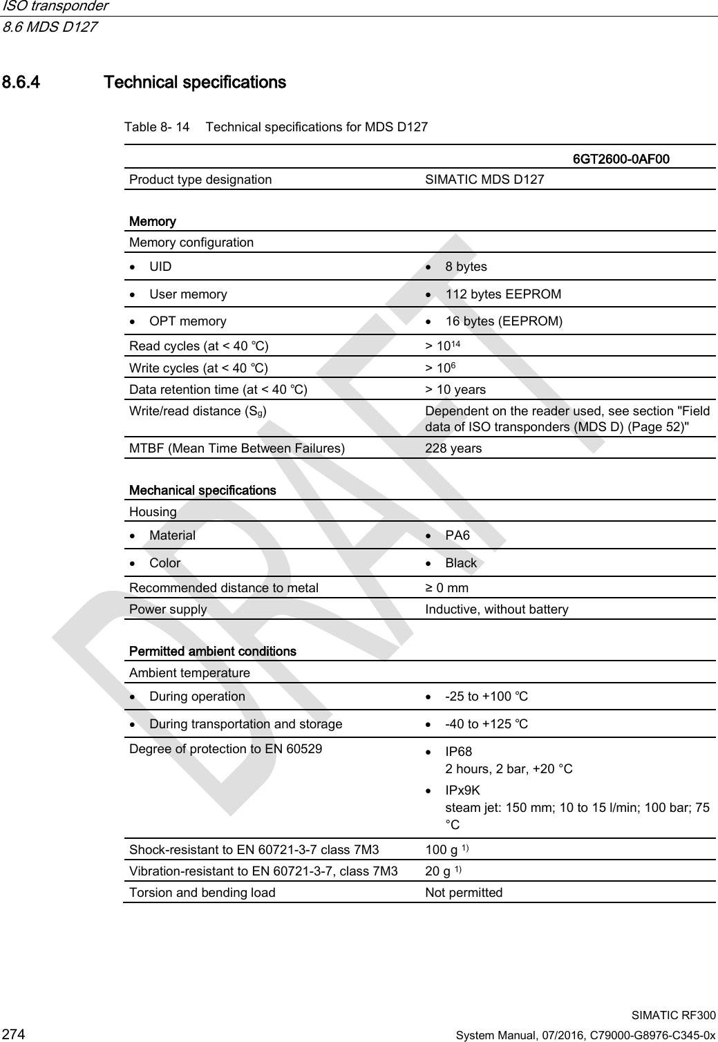
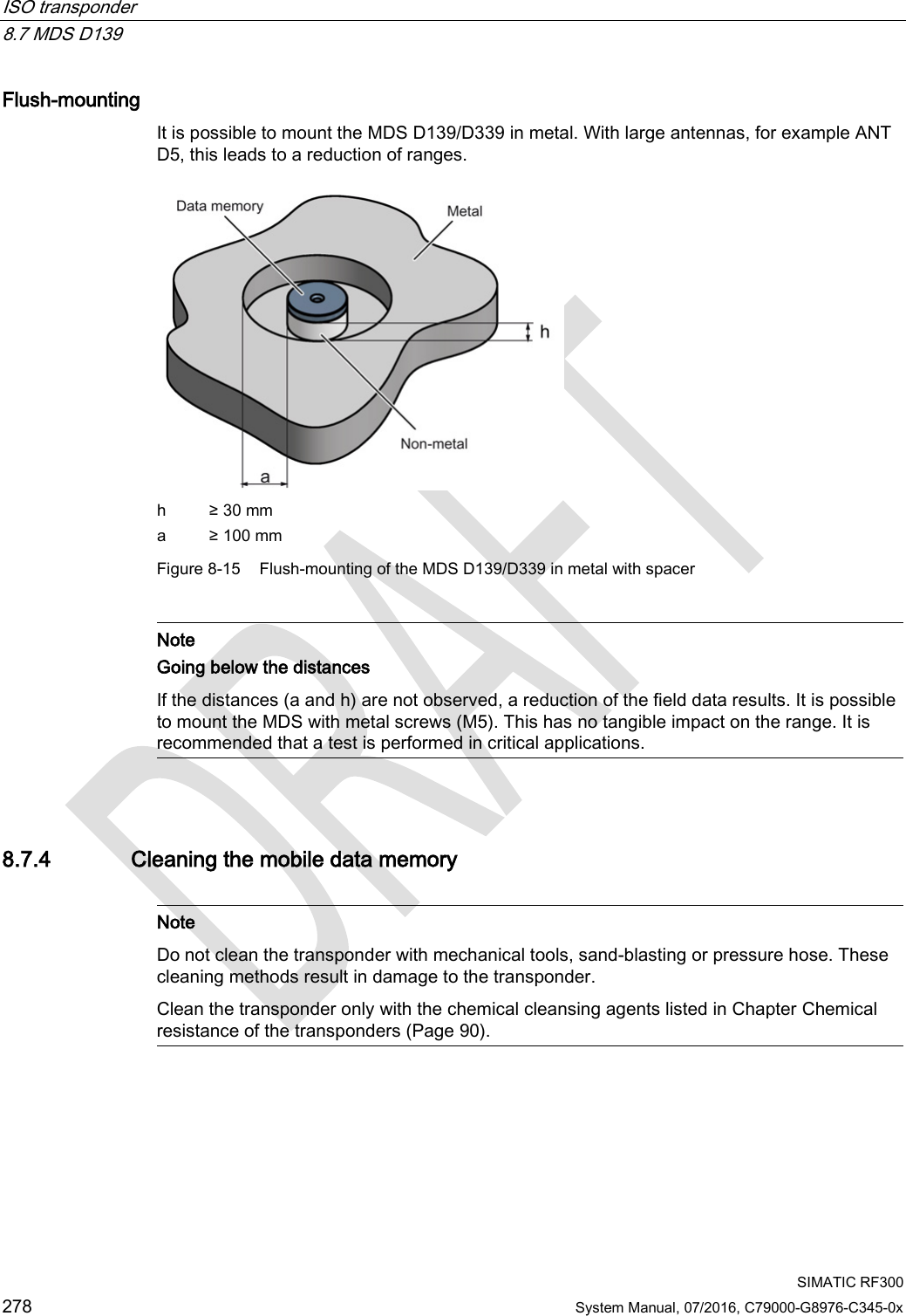
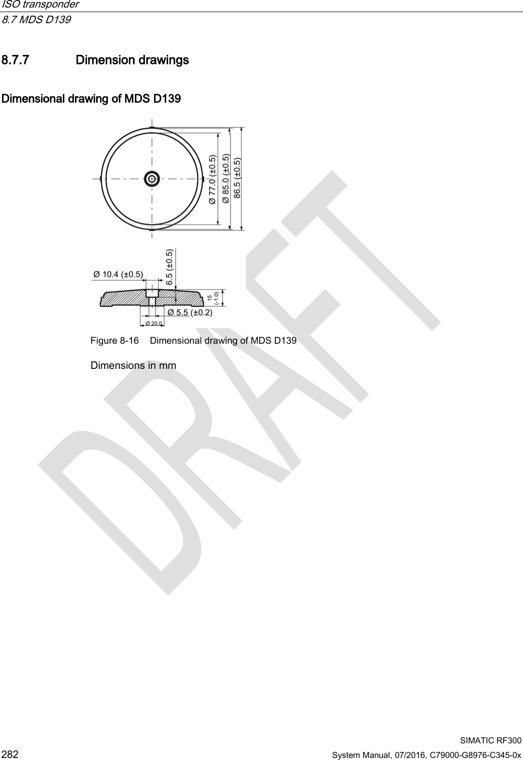
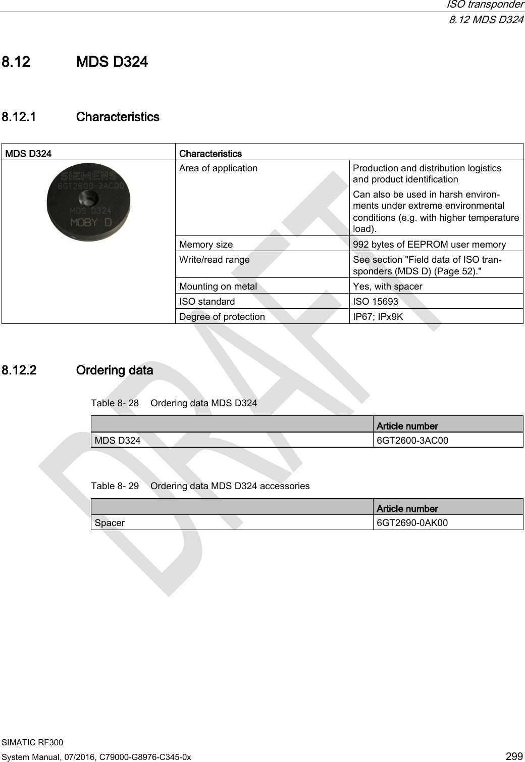
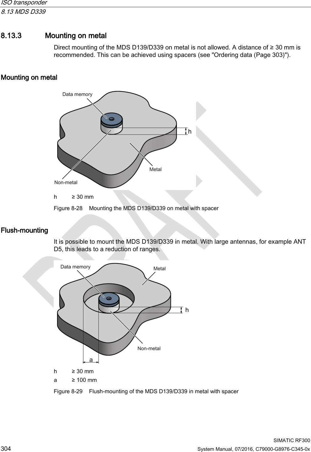
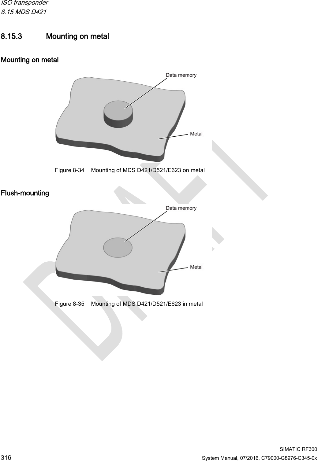
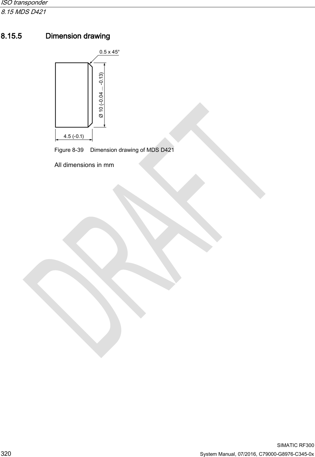
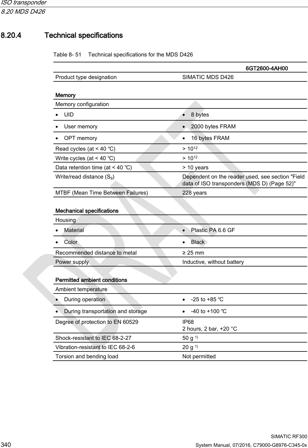
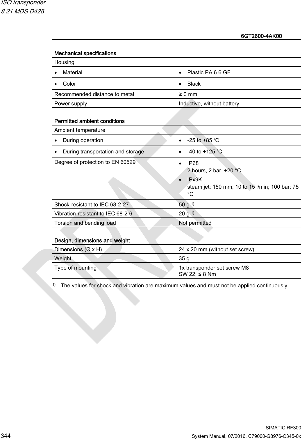
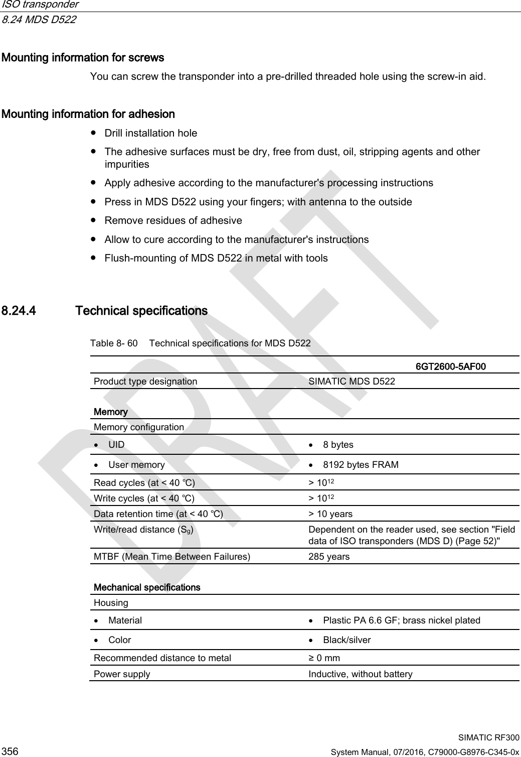
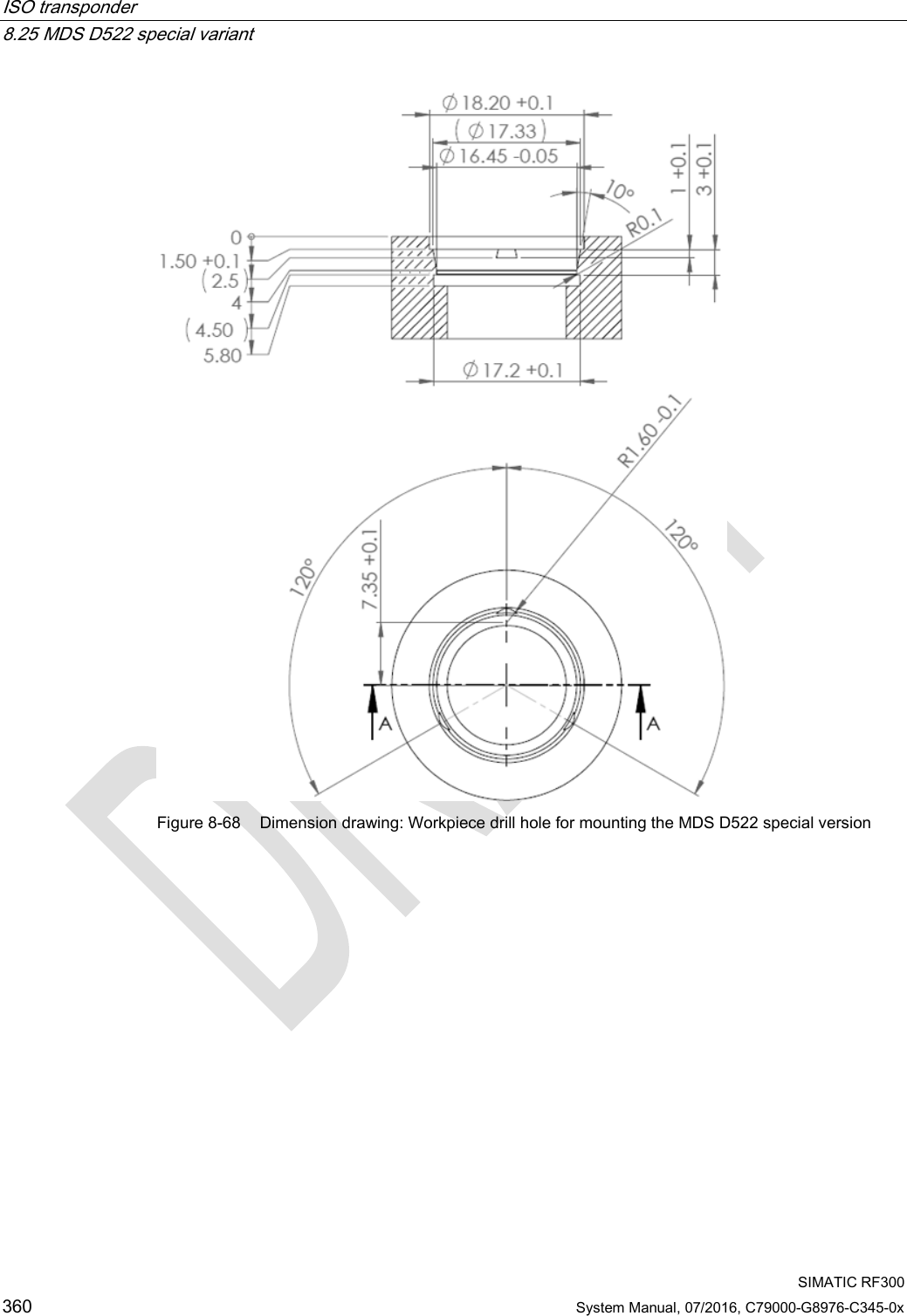
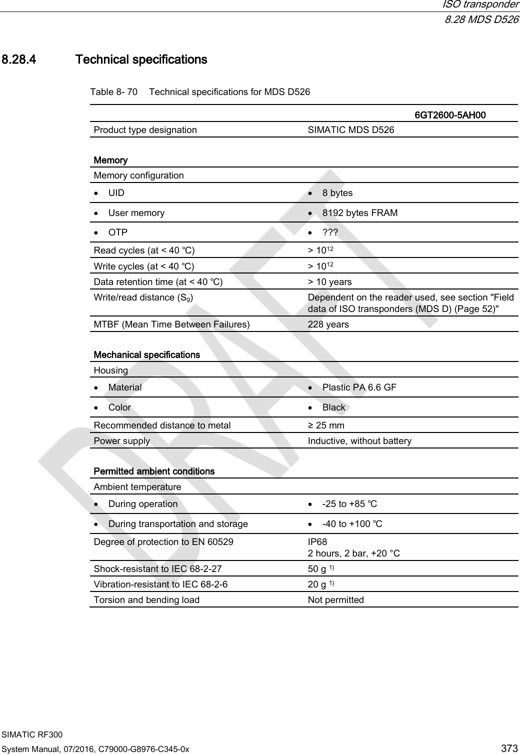
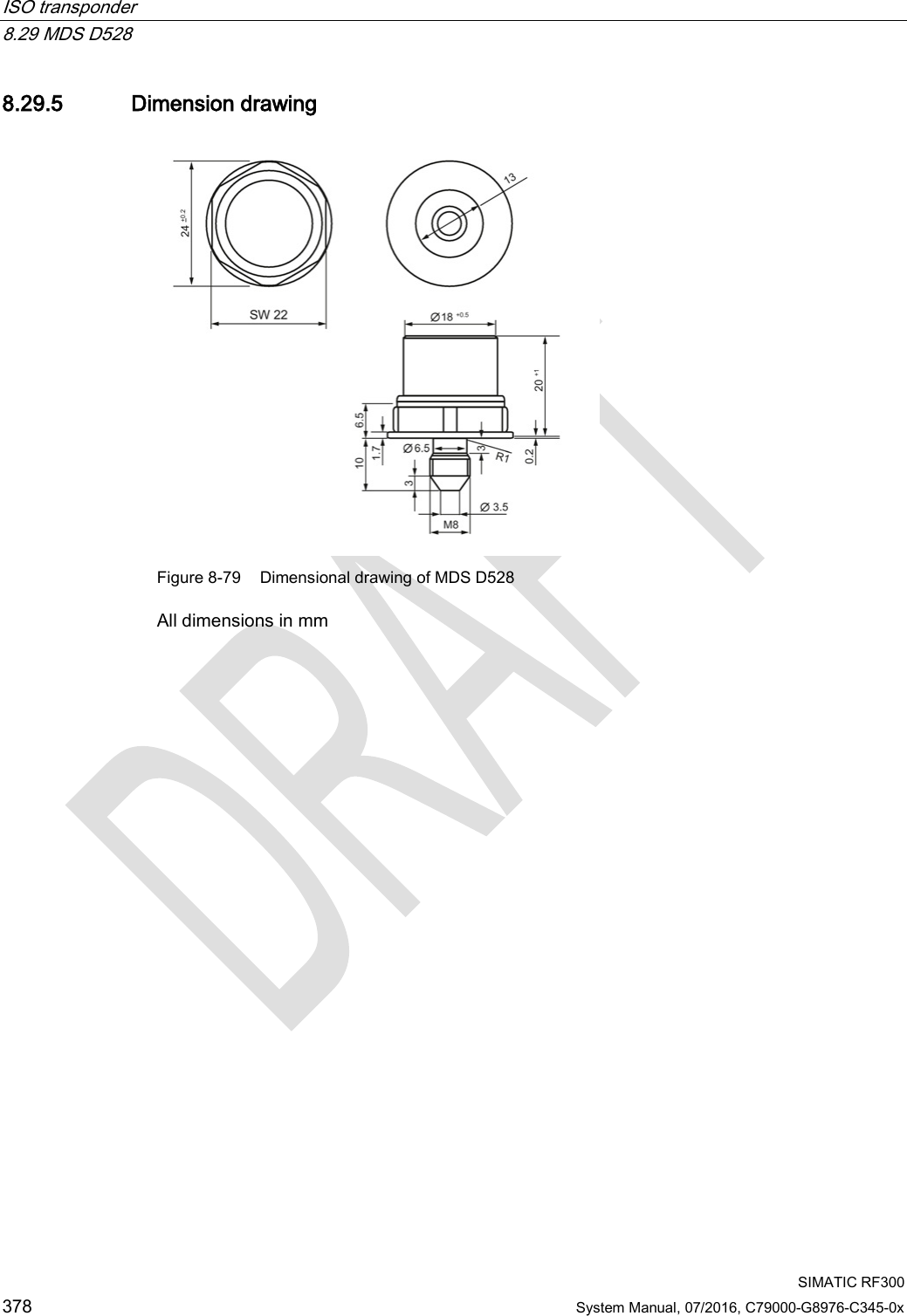
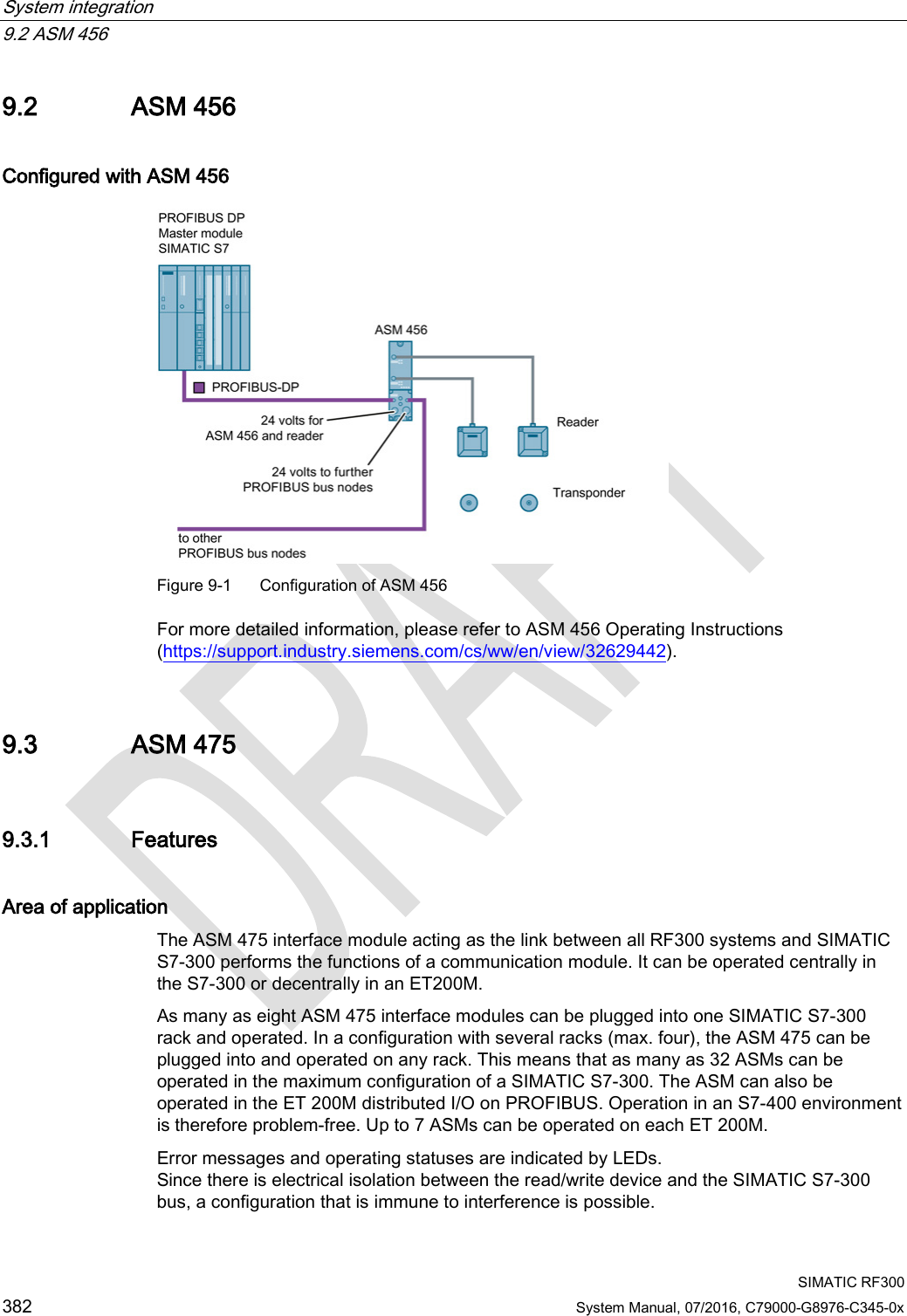
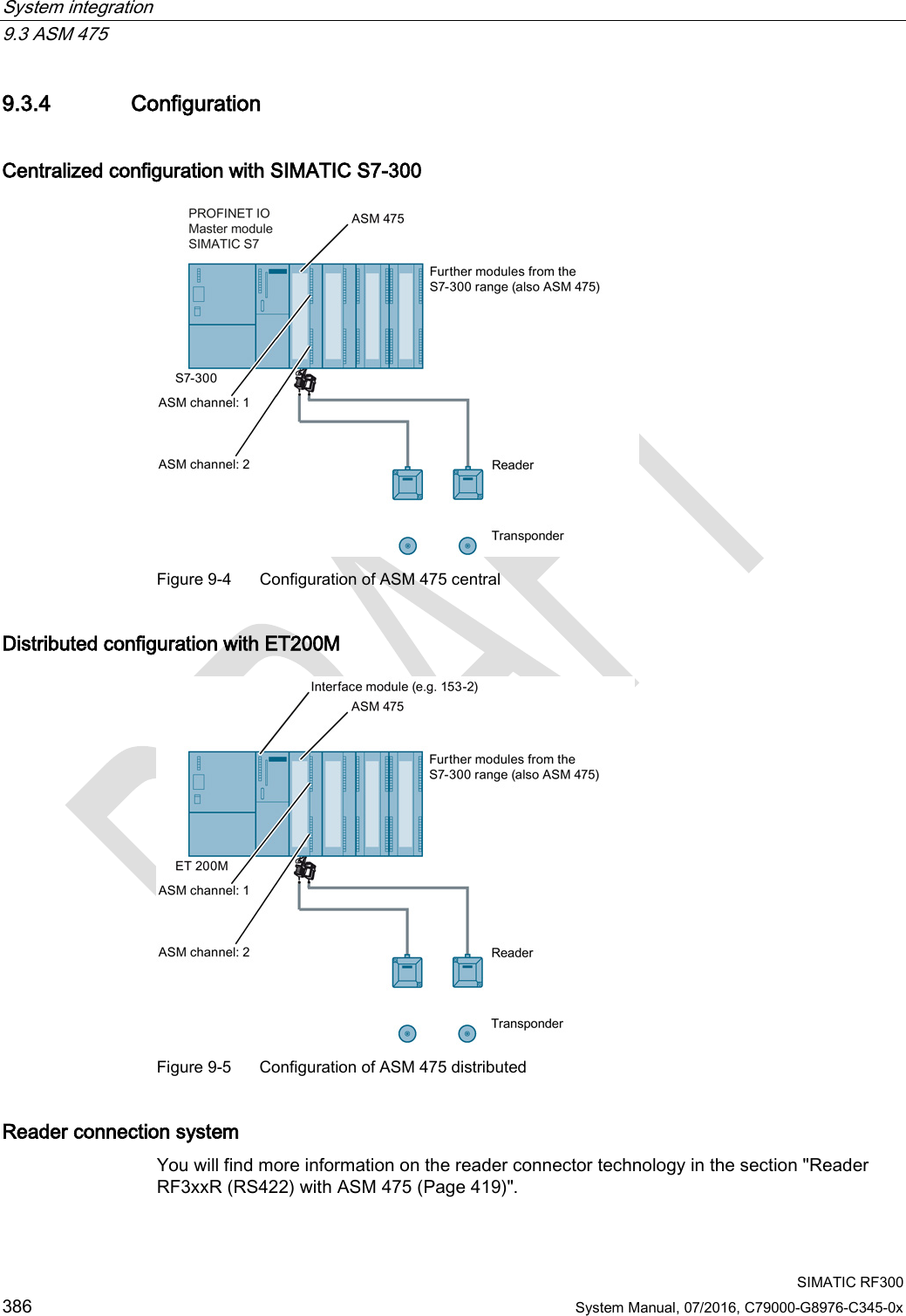
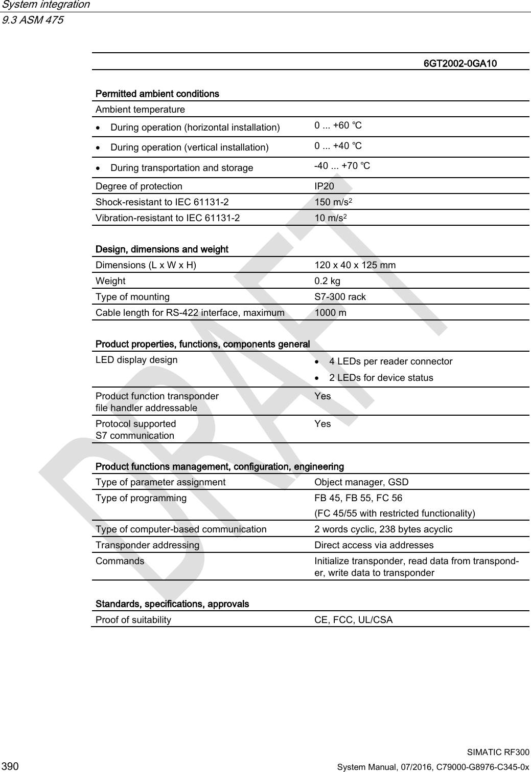
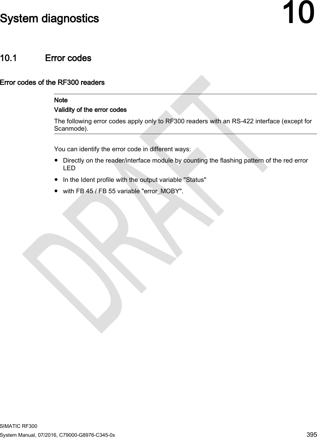
![Antennas 6.5 Minimum distance between antennas SIMATIC RF300 200 System Manual, 07/2016, C79000-G8976-C345-0x 6.5 Minimum distance between antennas Table 6- 3 Minimum distance between antennas Diagram (example) Minimum distance [mm] Antennas next to each other ANT 1 D ≥ 100 mm ANT 3 D ≥ 80 mm ANT 3S D ≥ 20 mm ANT 8 D ≥ 50 mm ANT 12 D ≥ 70 mm ANT 18 D ≥ 100 mm ANT 30 D ≥ 100 mm Antennas face to face ANT 1 D ≥ 500 mm ANT 3 D ≥ 100 mm ANT 3S D ≥ 50 mm ANT 8 D ≥ 50 mm ANT 12 D ≥ 100 mm ANT 18 D ≥ 100 mm ANT 30 D ≥ 200 mm The reader electronics can be mounted directly alongside each other.](https://usermanual.wiki/Siemens/RF340R02.User-Manual-part-2/User-Guide-3093595-Page-8.png)


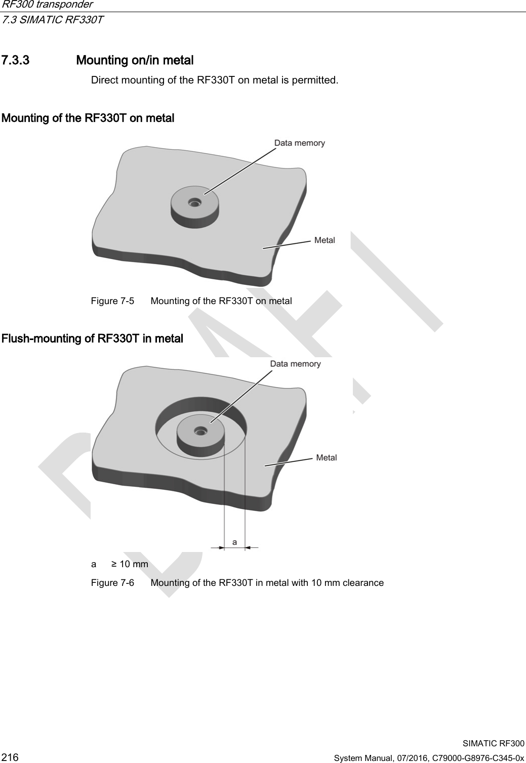
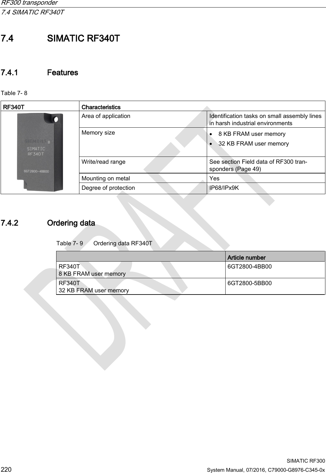
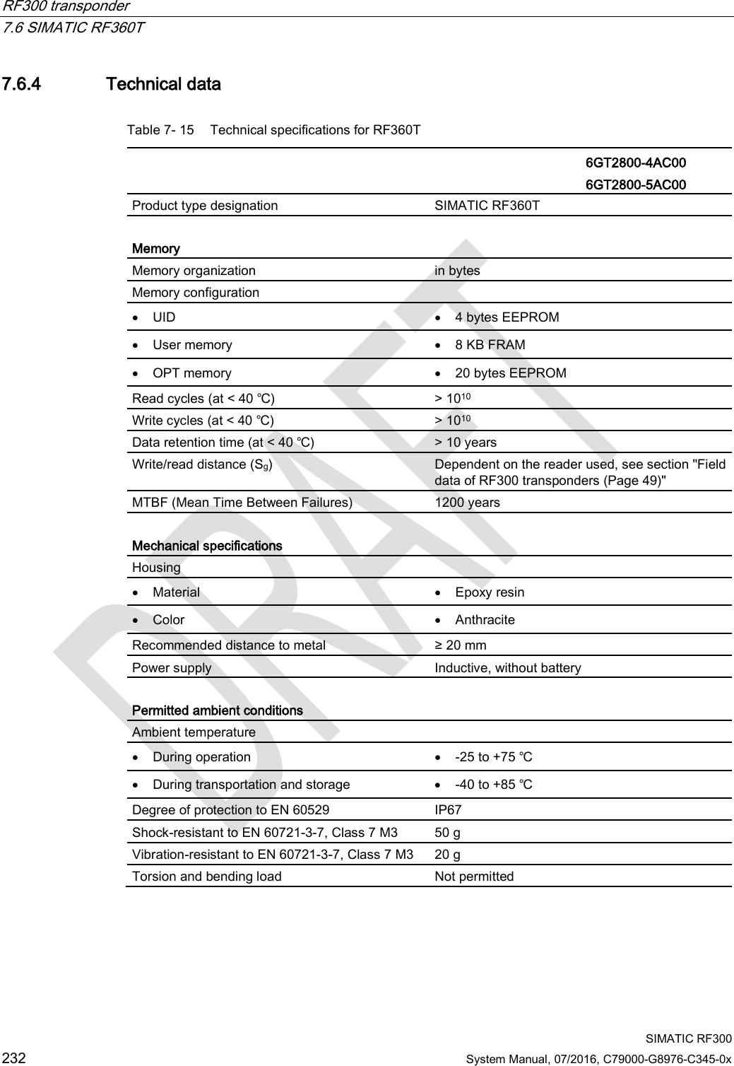
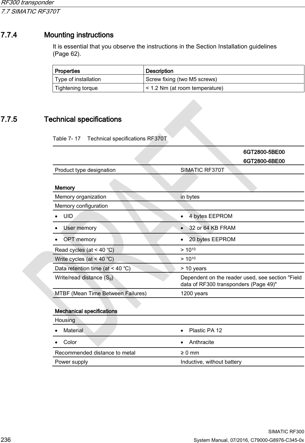
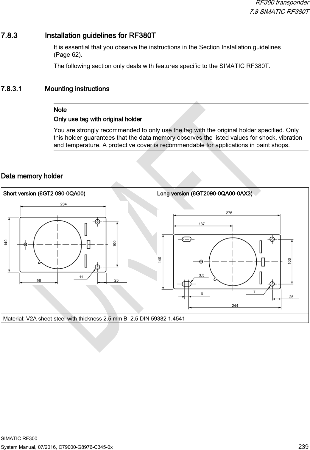
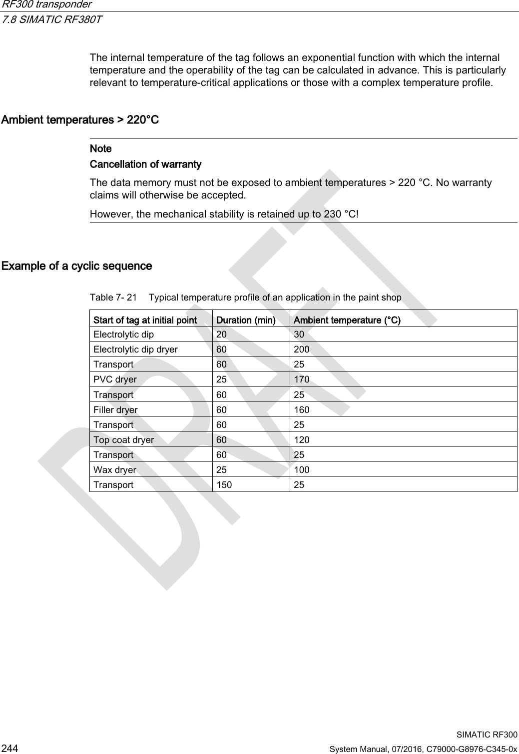
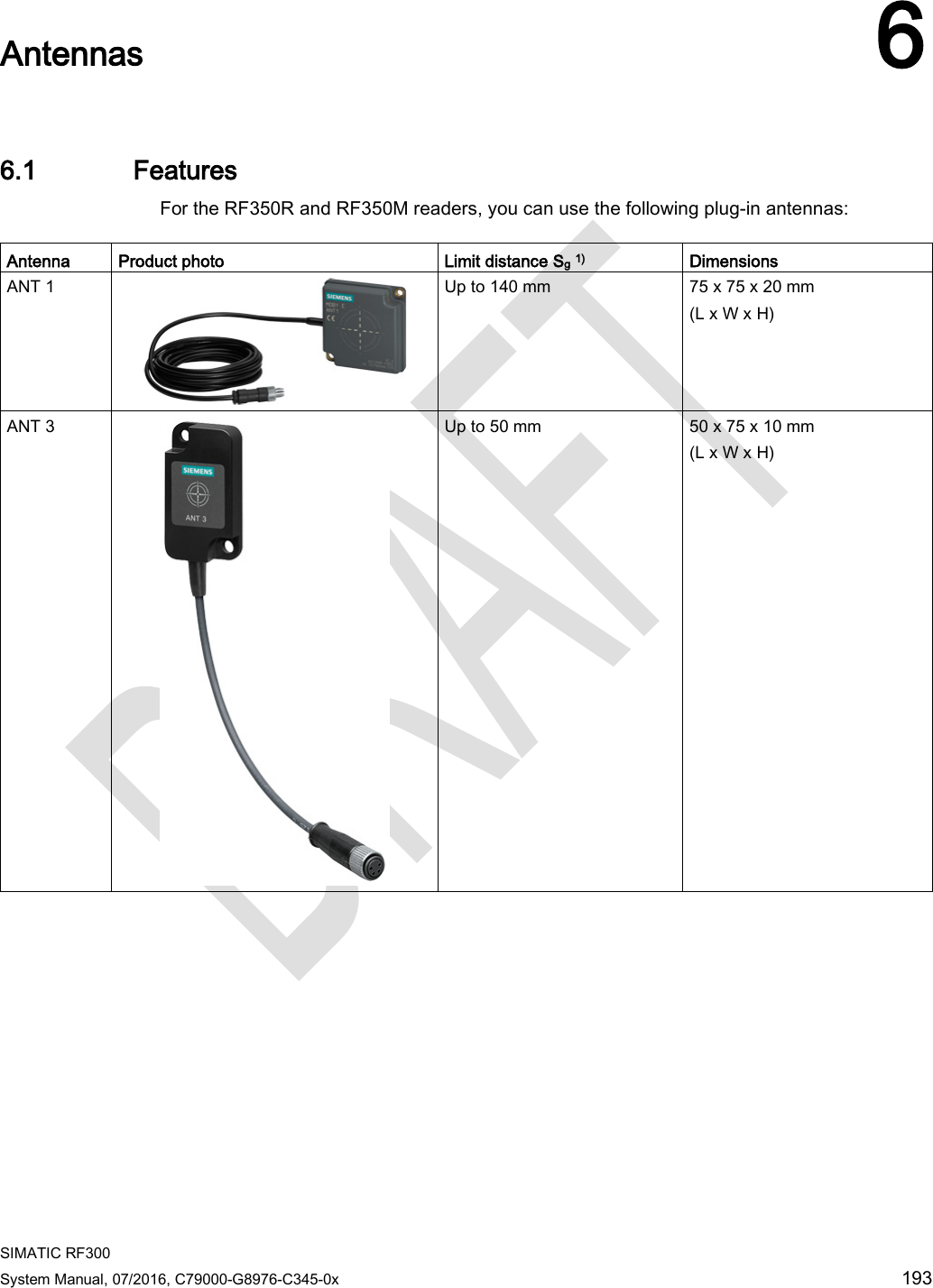
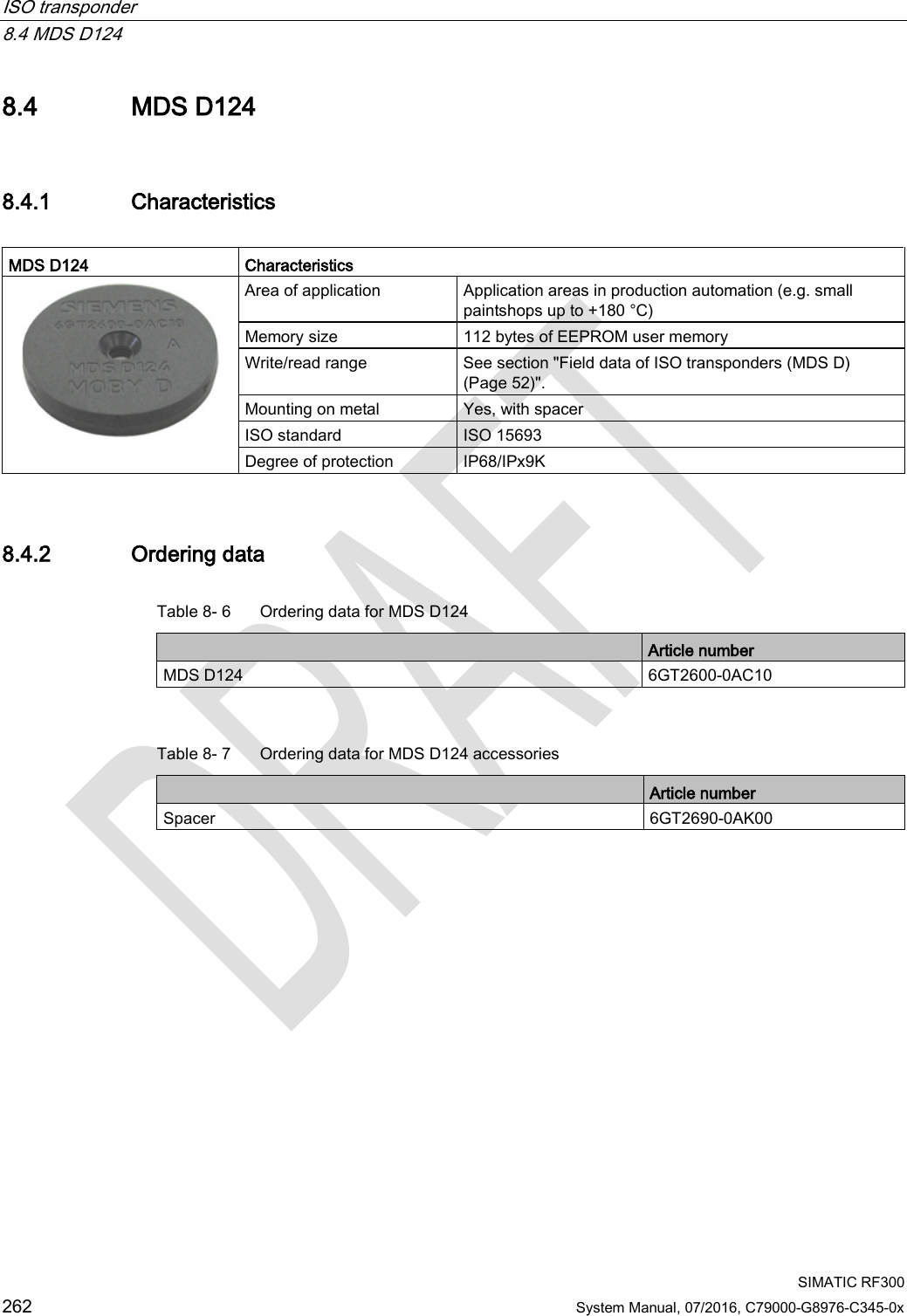
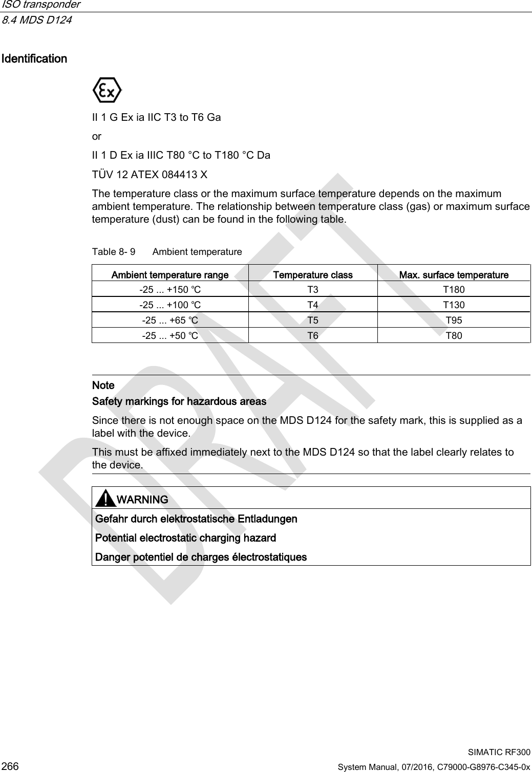
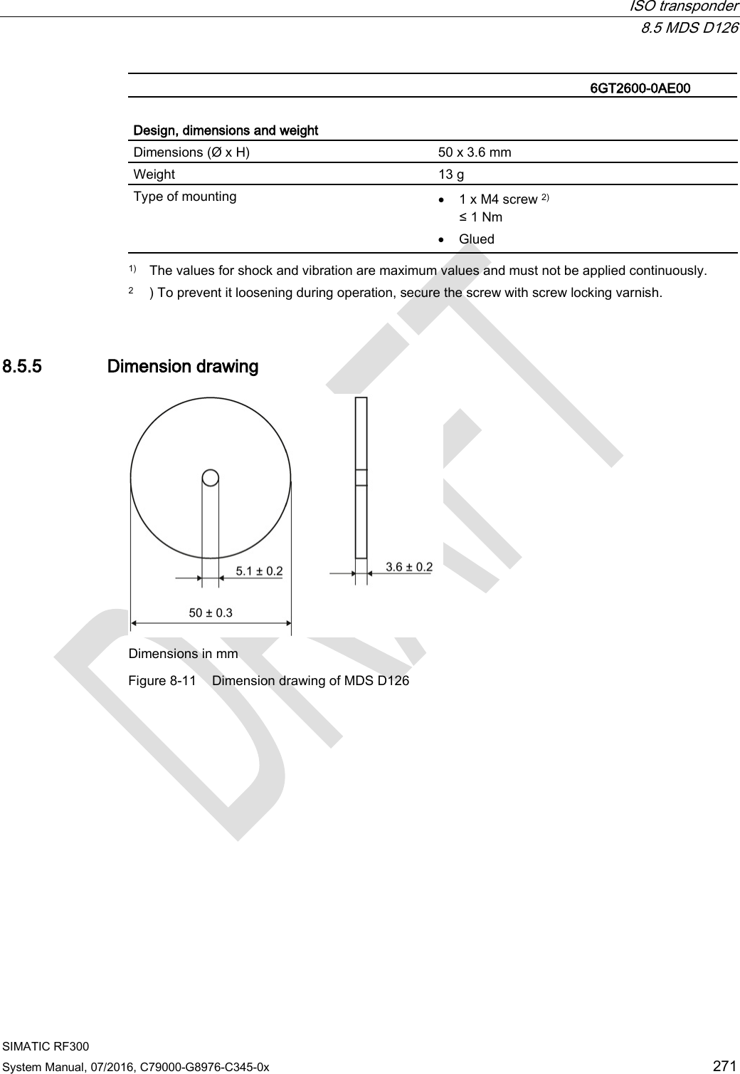
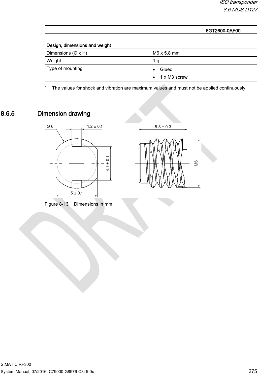
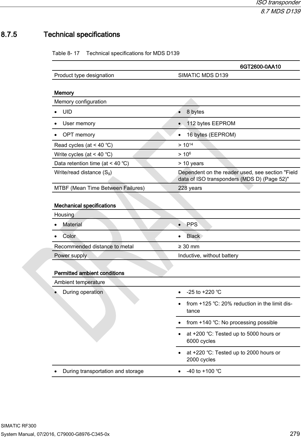
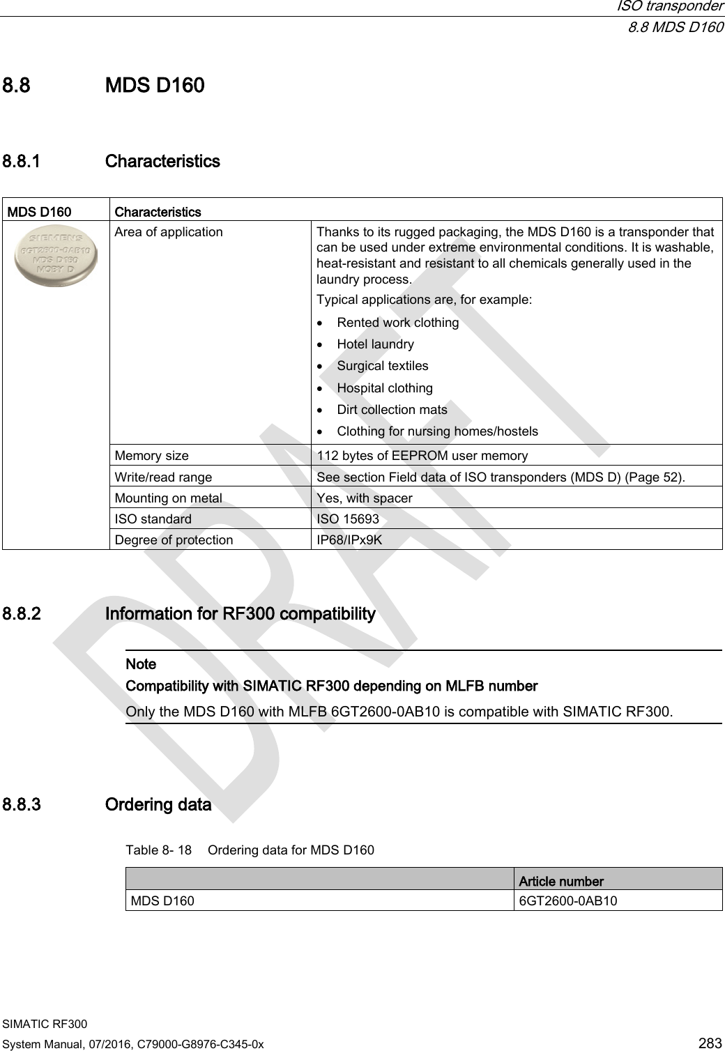
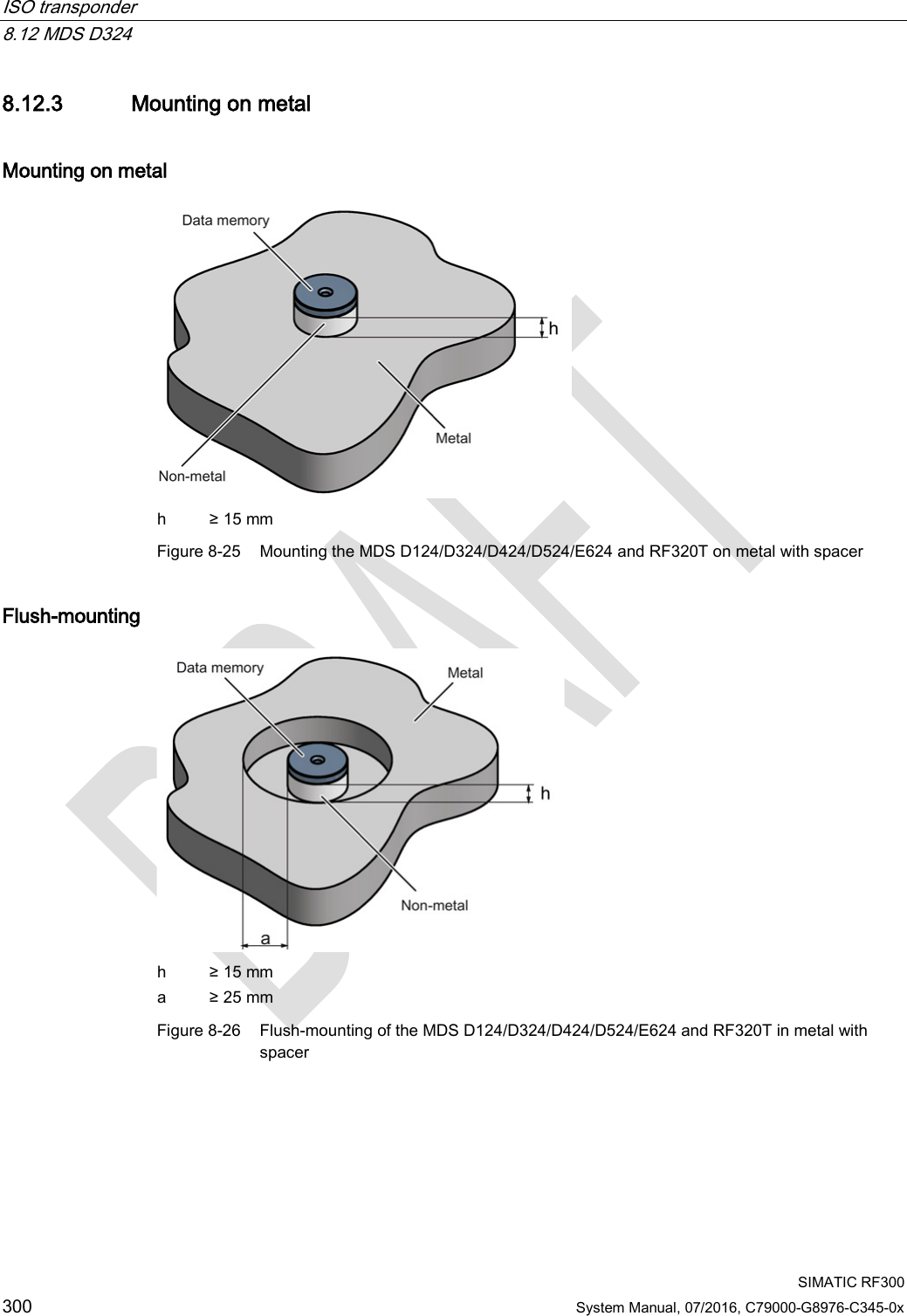
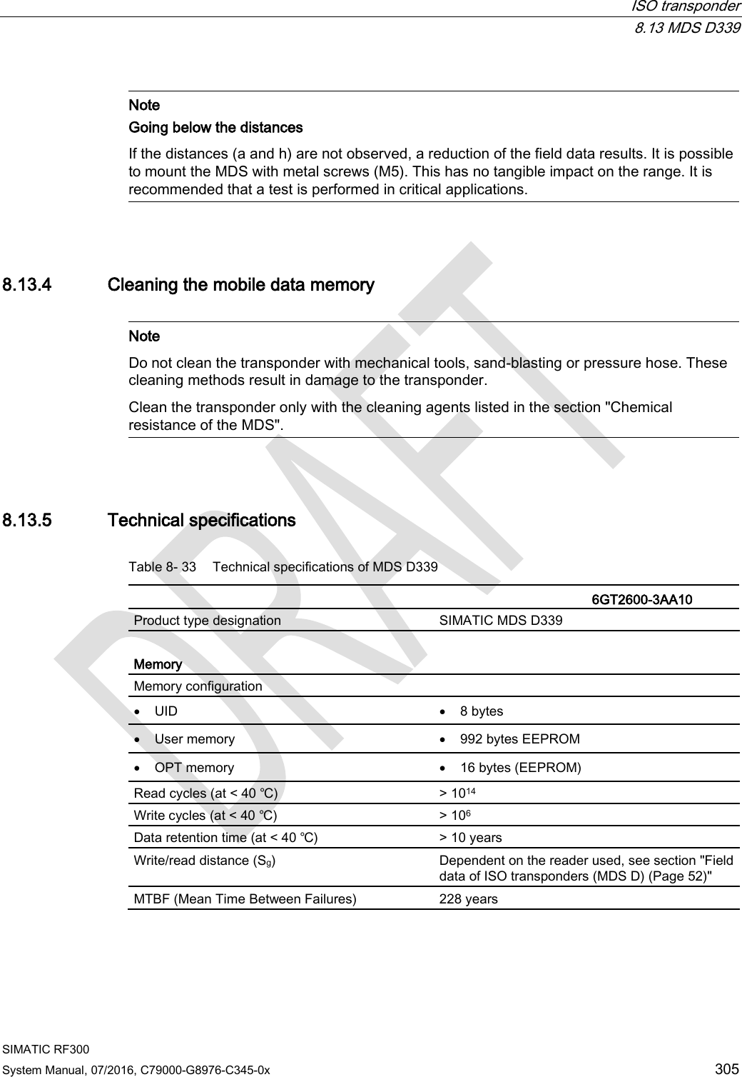
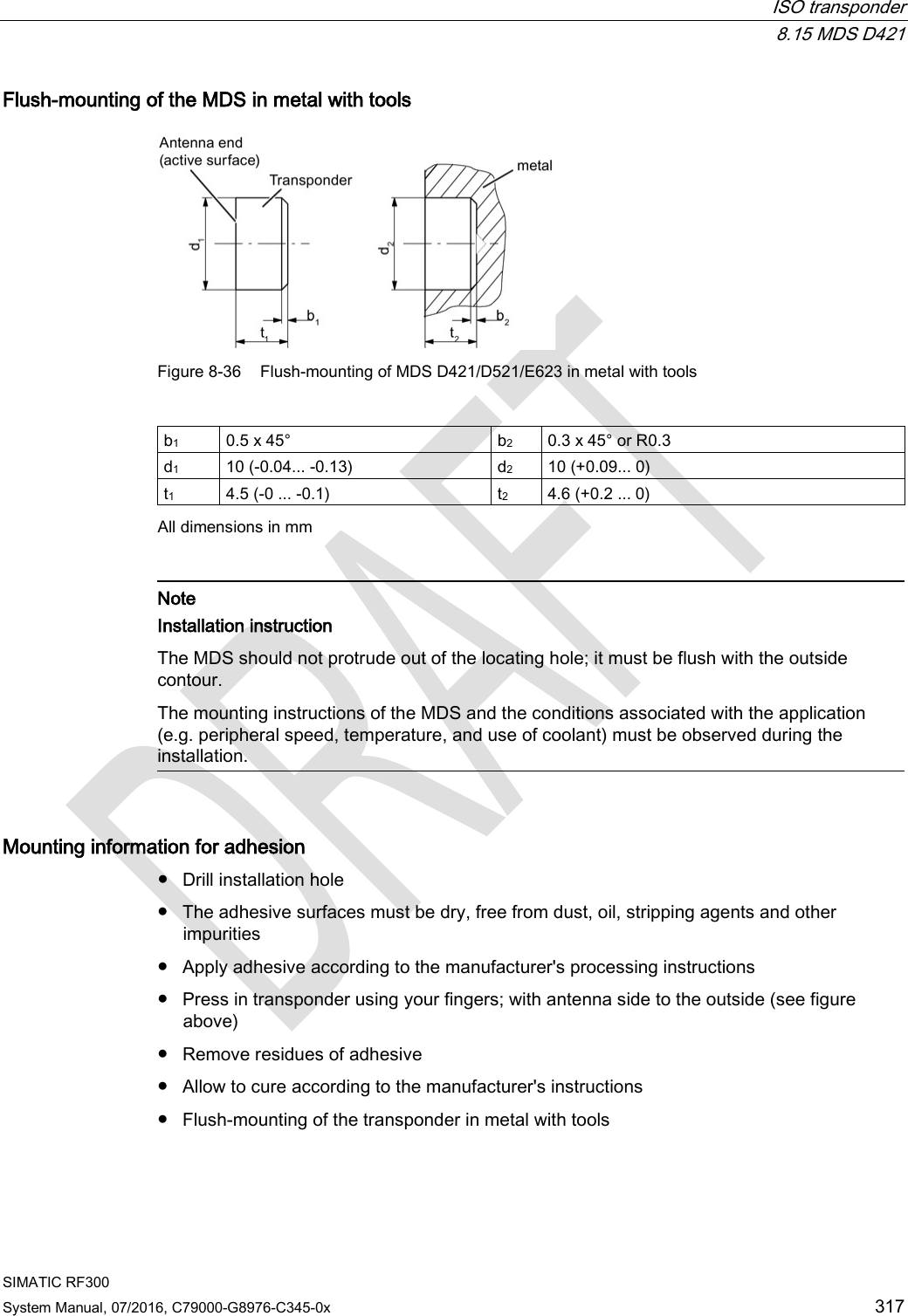
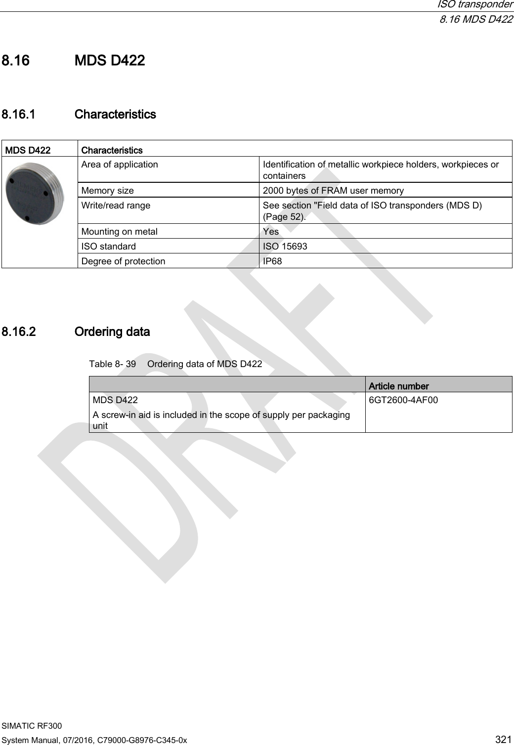
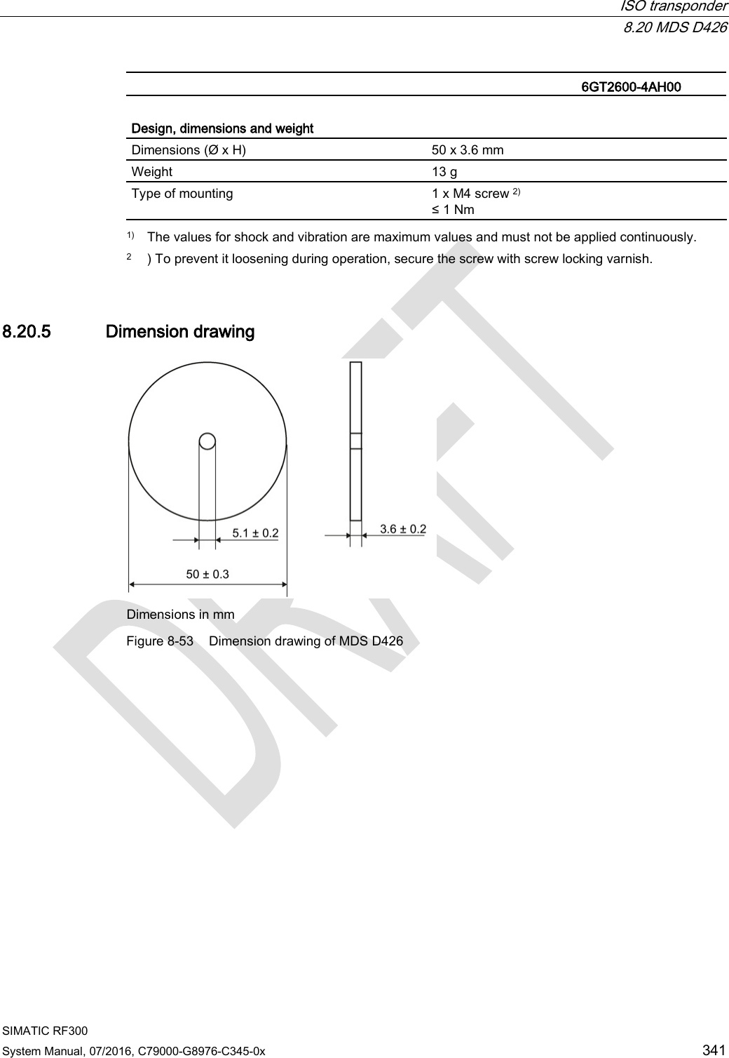
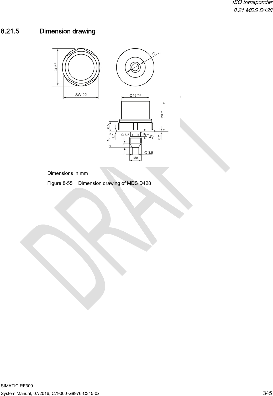
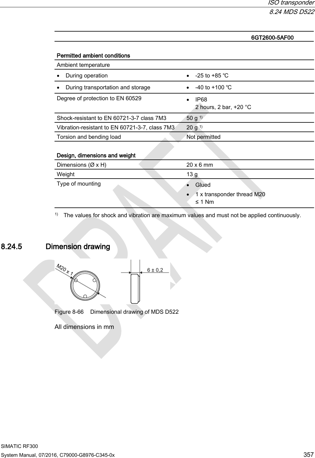
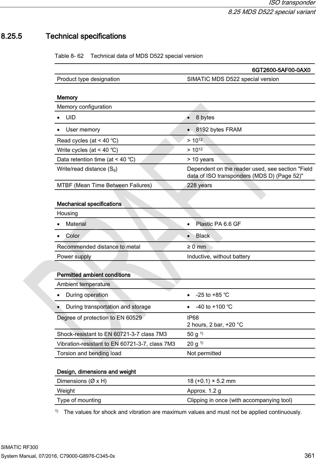
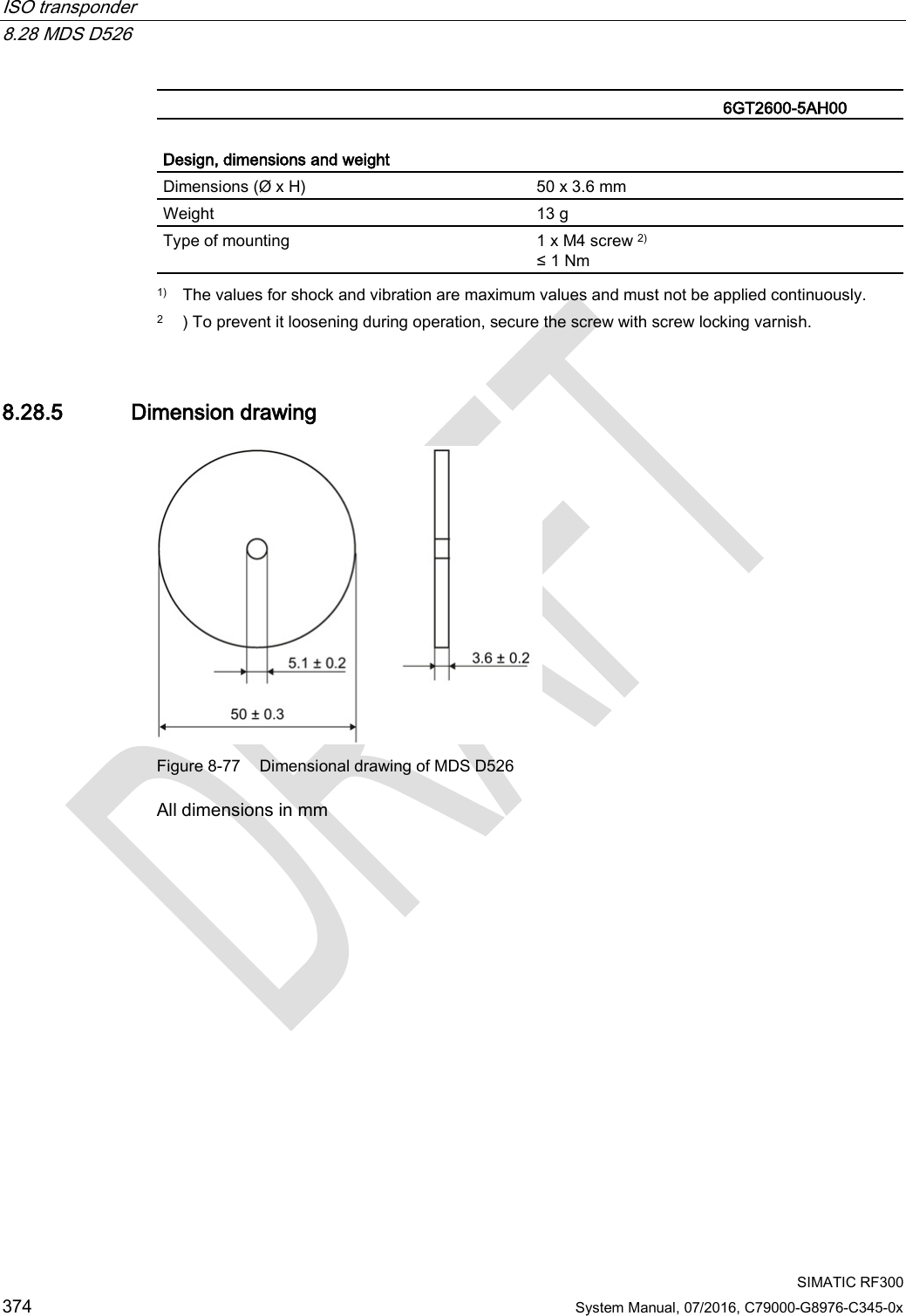
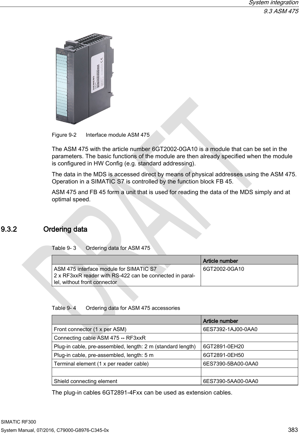
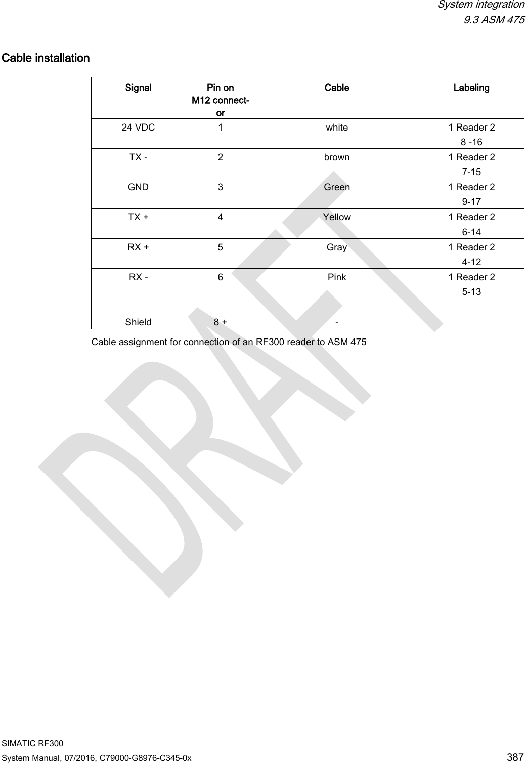
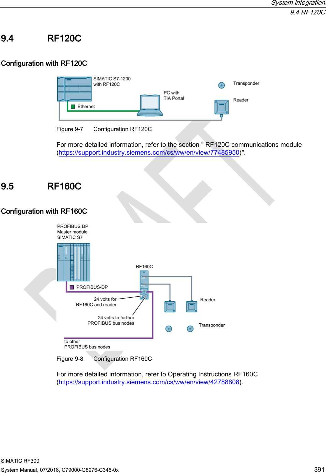
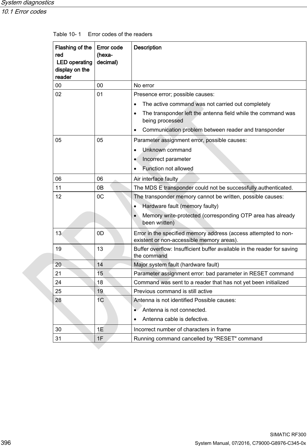
![RF300 transponder 7.8 SIMATIC RF380T SIMATIC RF300 246 System Manual, 07/2016, C79000-G8976-C345-0x 7.8.5 Use of the transponder in the Ex protection area The TÜV SÜD Automotive GmbH as approved test center as well as the TÜV SÜD Product Service GmbH as certification center, identification number 0123, as per Article 9 of the Directive of the European Council of 23 March 1994 (94/9/EC), has confirmed the compliance with the essential health and safety requirements relating to the design and construction of equipment and protective systems intended for use in hazardous areas as per Annex II of the Directive. The essential health and safety requirements are satisfied in accordance with the following standards: Table 7- 22 Approvals Document Title EN 60079-0: 2006 Electrical equipment for hazardous gas atmospheres - Part 0: General requirements EN 60079-15: 2005 Electrical equipment for hazardous gas atmospheres - Part 15: Design, testing and identification of electrical equipment with type of protection "n" DIN VDE 0848-5: 2001 (in parts) Safety in electrical, magnetic and electromagnetic fields - Part 5: Explosion protection ZLS SK 107.1 Central office of the states for safety; test components Identification Table 7- 23 The identification of the electrical equipment as an encapsulated unit II 3G Ex nC IIB T5 -25°C to +70°C Um=30Vdc The equipment is assigned the following references: XXXYYYZZZ [= serial number, is assigned during production] TPS 09 ATEX 1 459 X [= certificate number] "No use of the equipment in the vicinity of processes generating high charges" 7.8.5.1 Use of the transponder in hazardous areas for gases Temperature class delineation for gases The temperature class of the transponder for hazardous areas depends on the ambient temperature range: Ambient temperature range Temperature class -25 °C to +70 °C T5](https://usermanual.wiki/Siemens/RF340R02.User-Manual-part-2/User-Guide-3093595-Page-54.png)

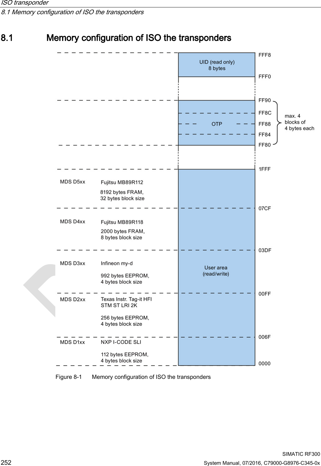
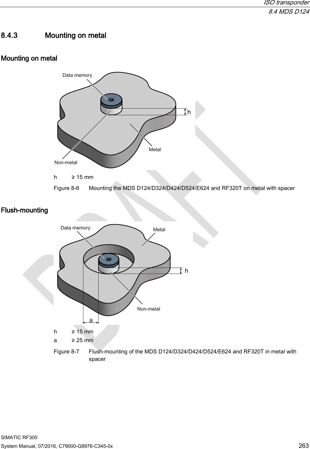
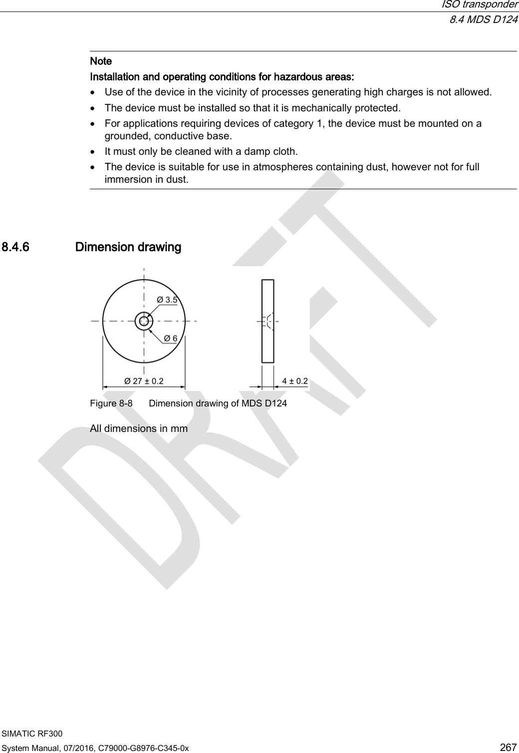

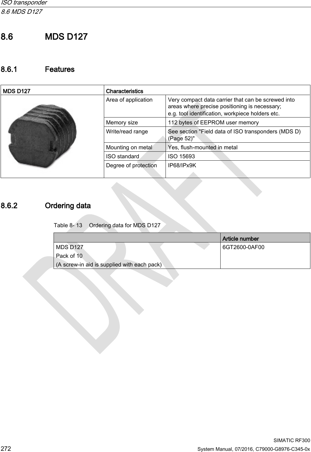
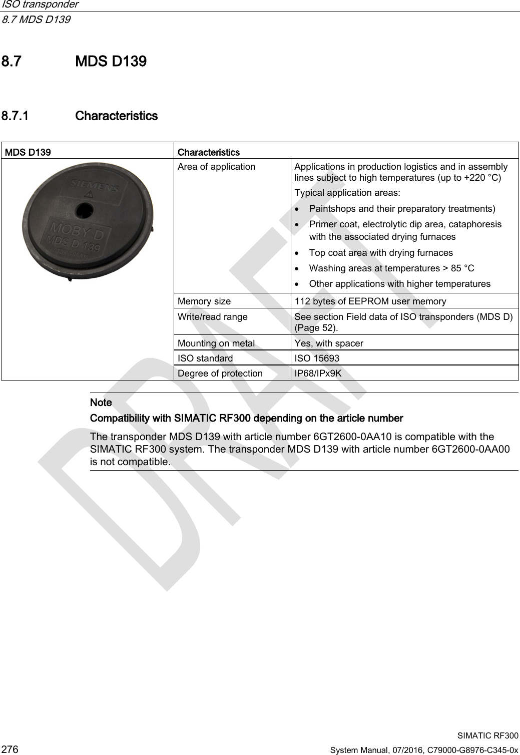
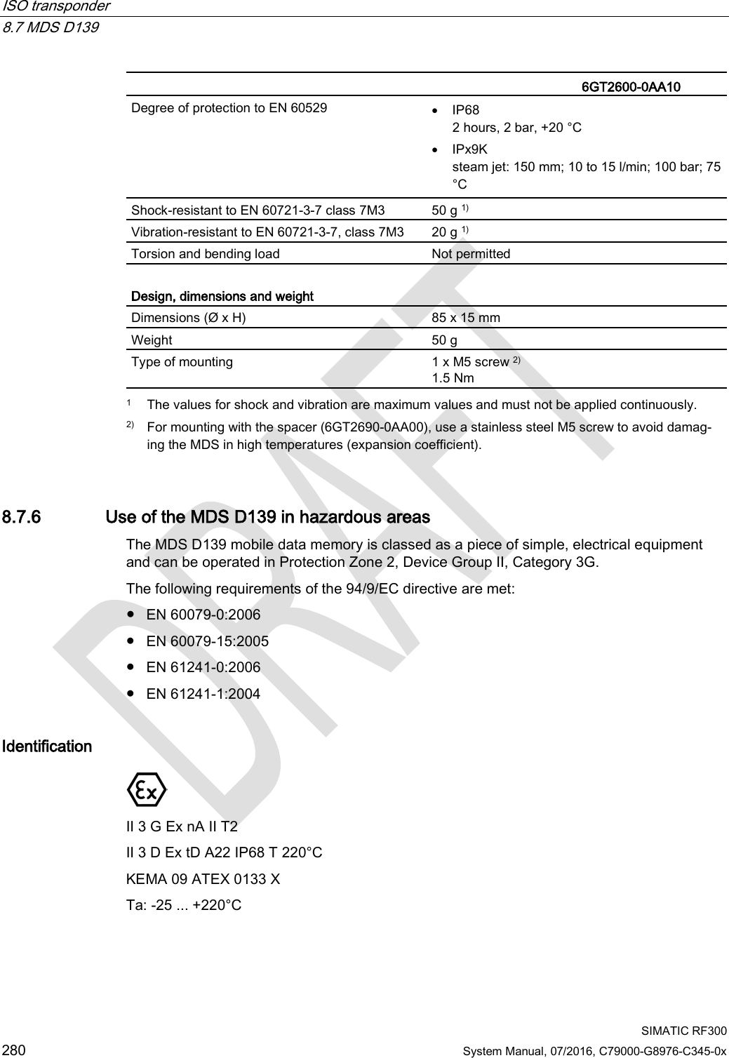
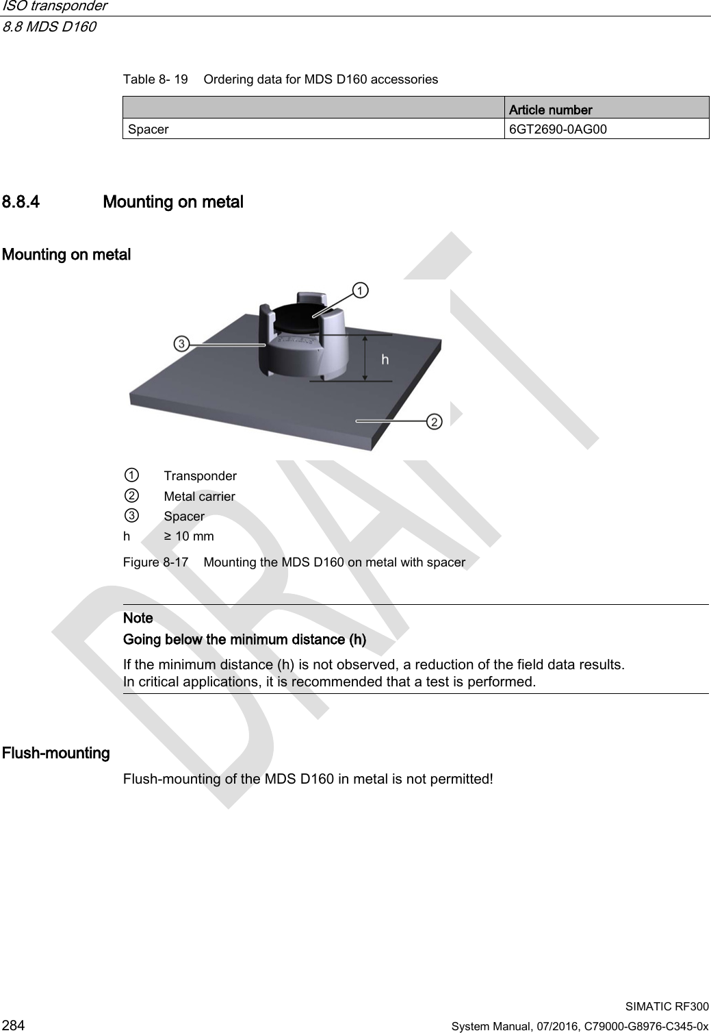

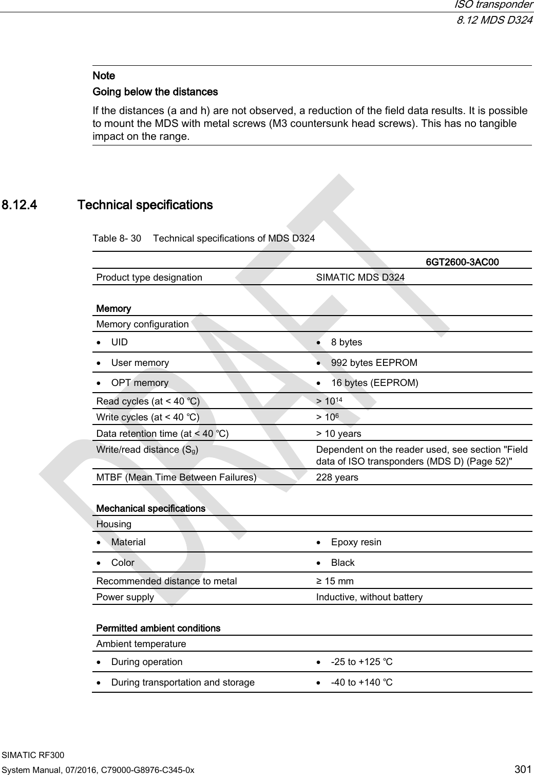

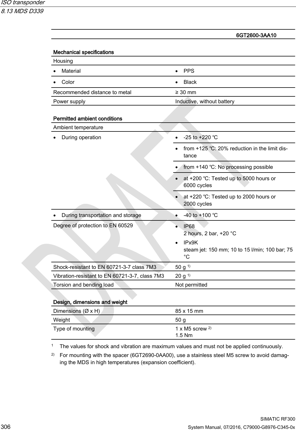
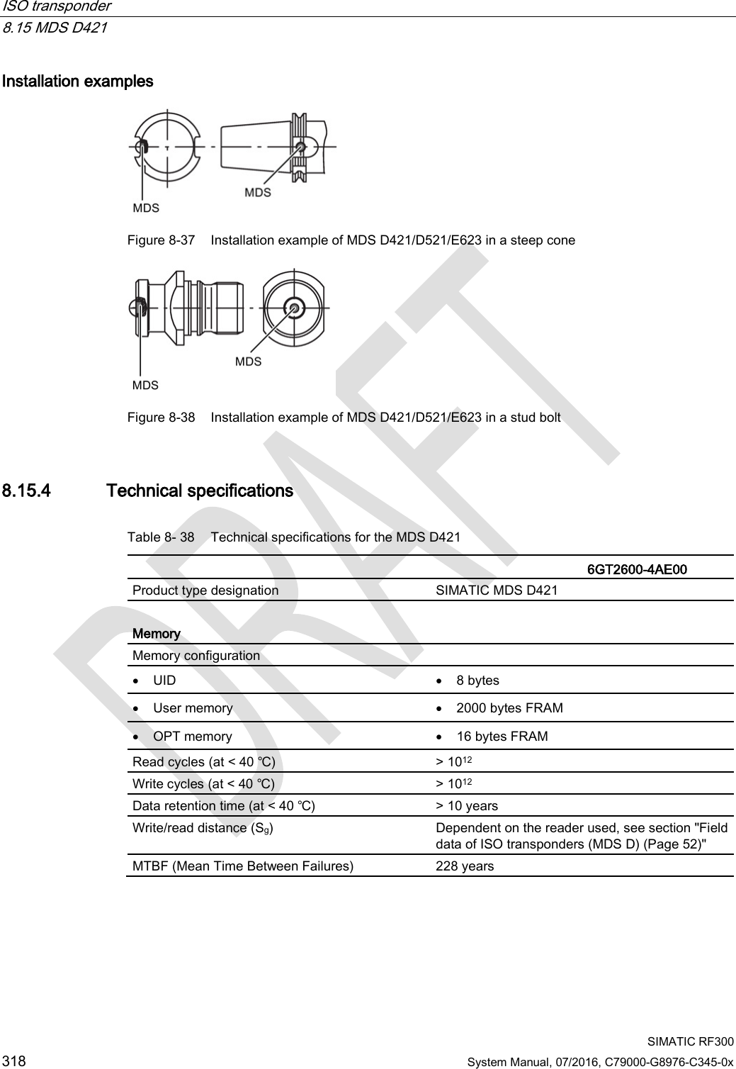
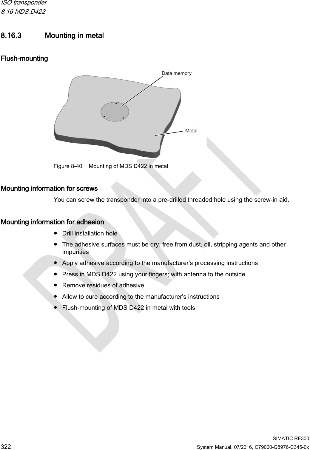


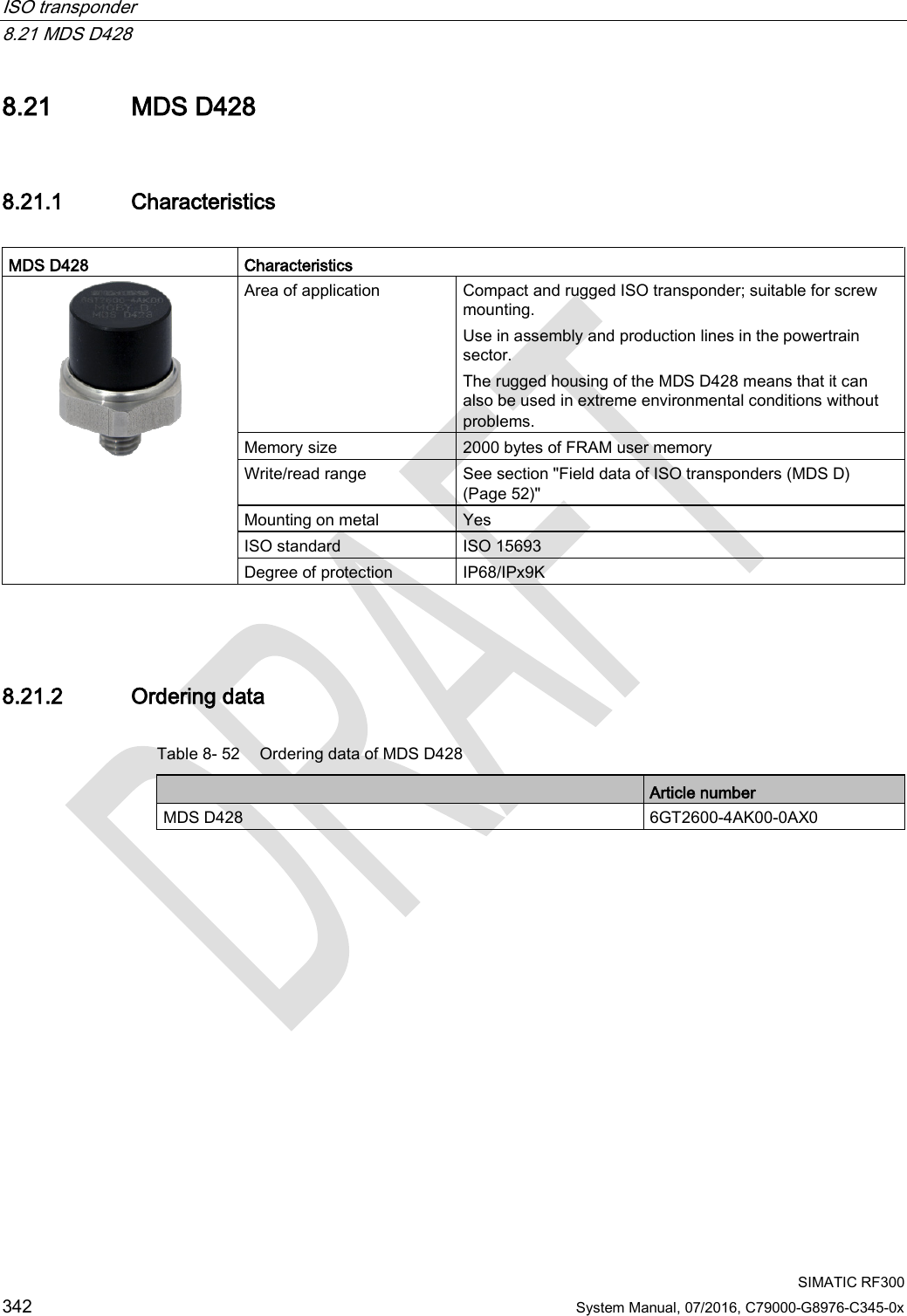
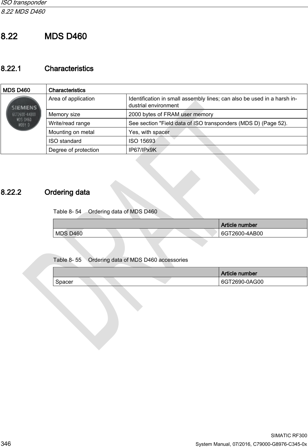
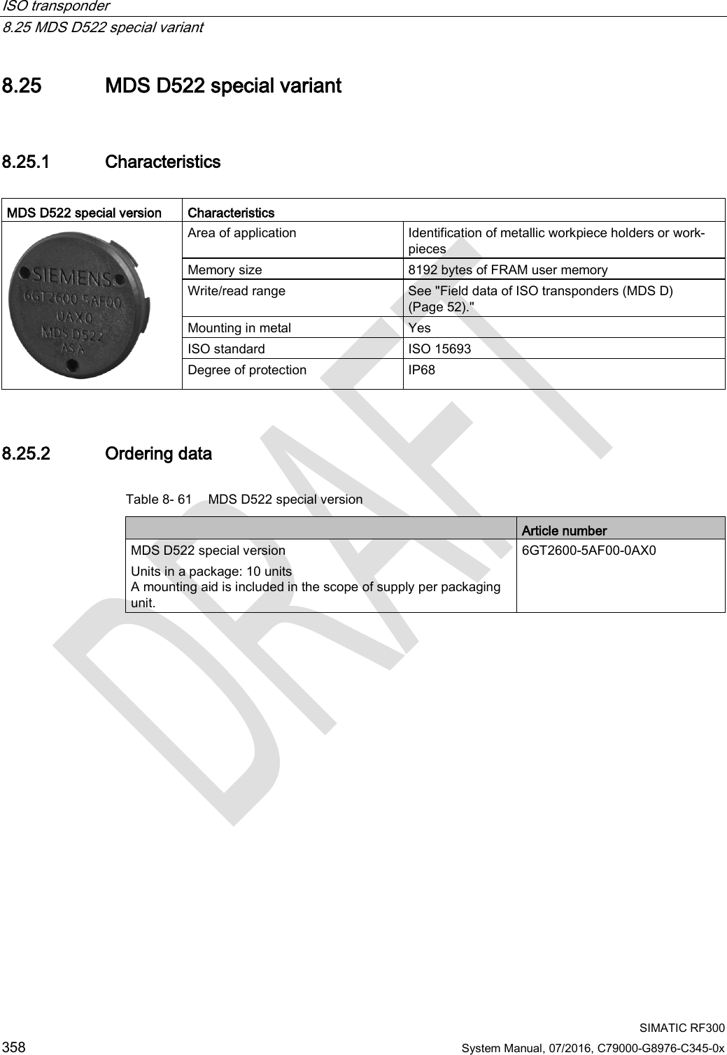
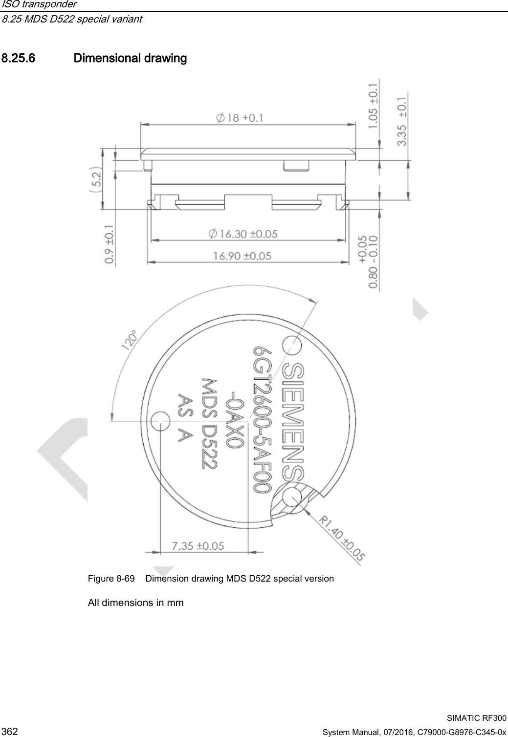

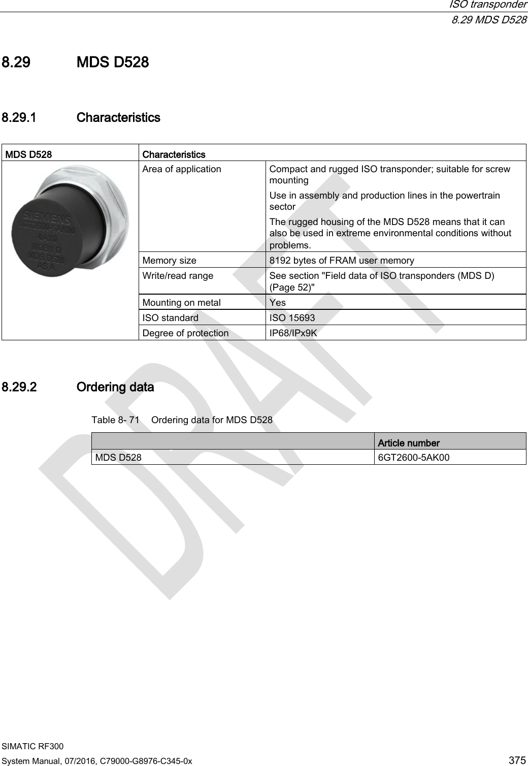

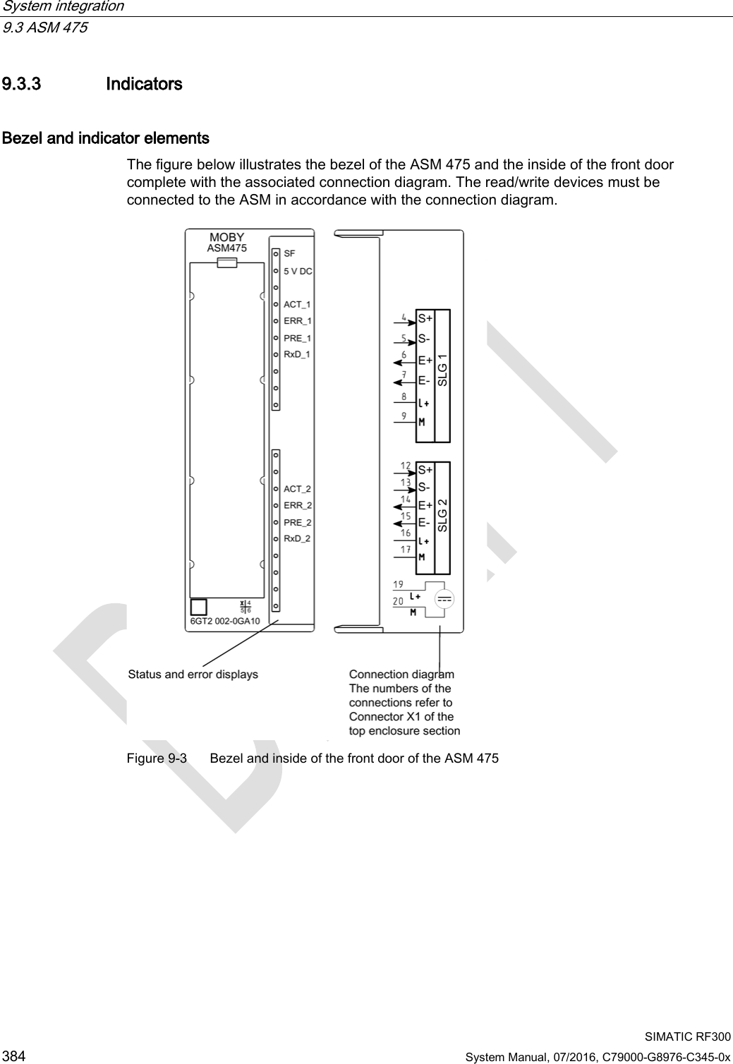
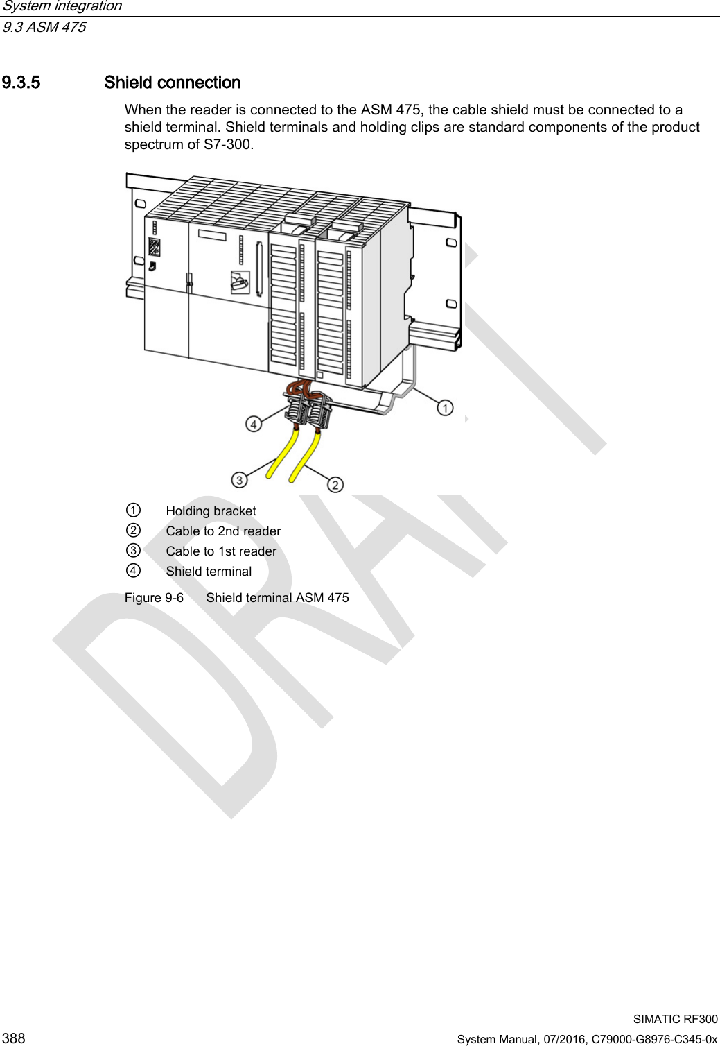

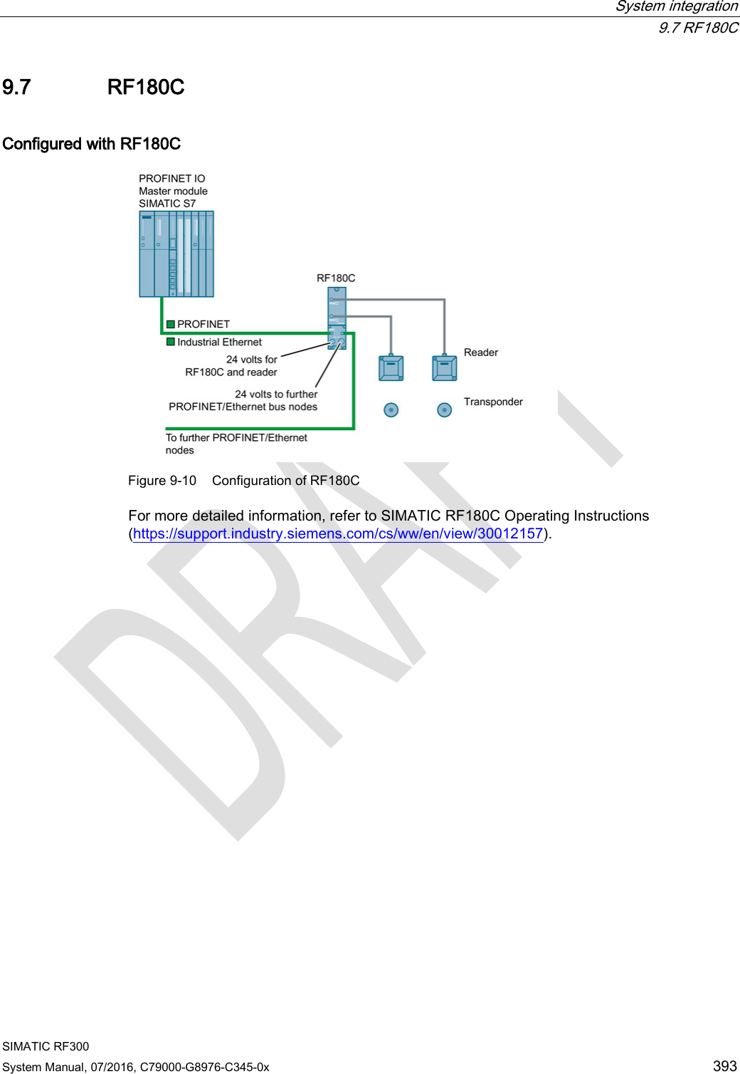
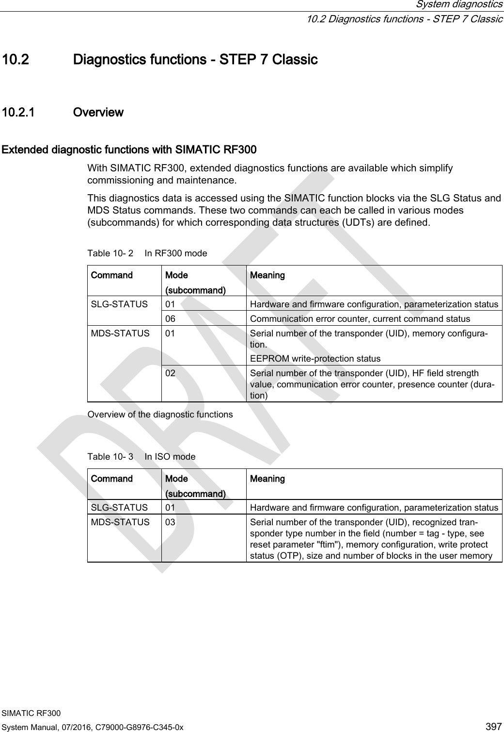
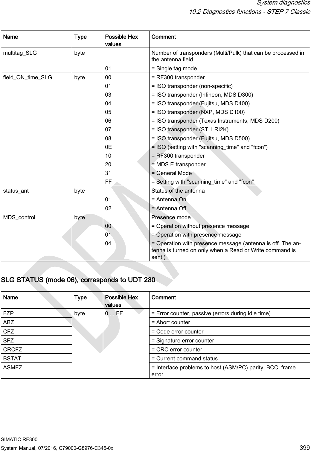
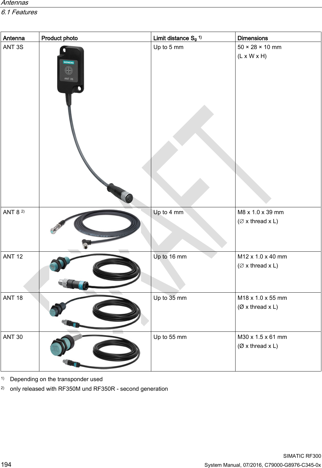
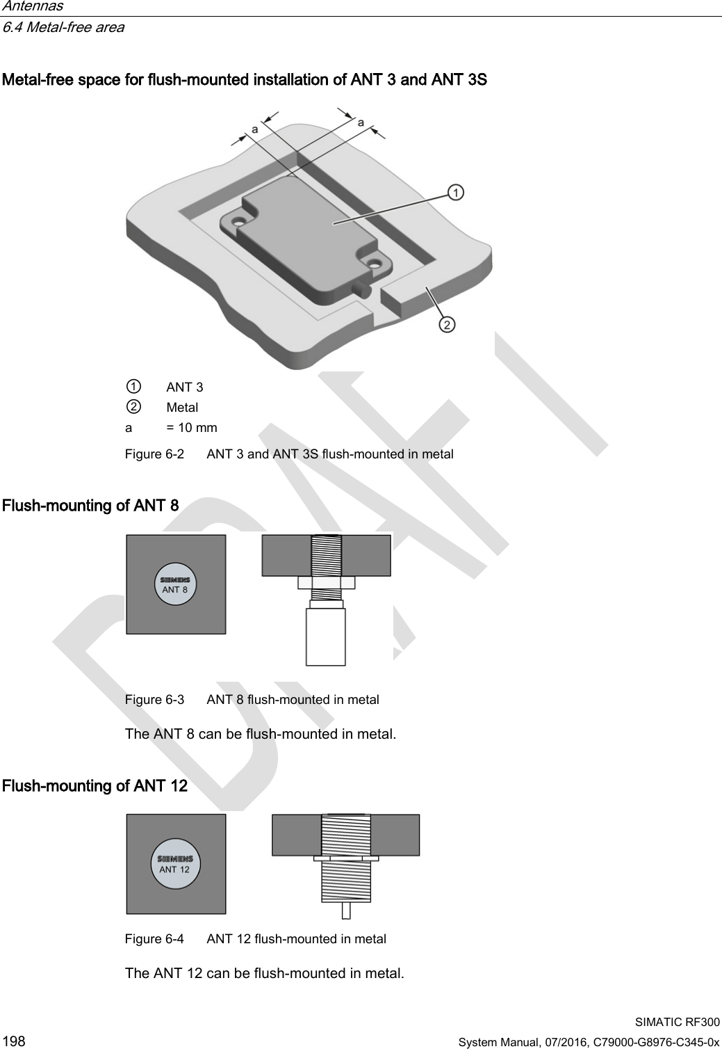
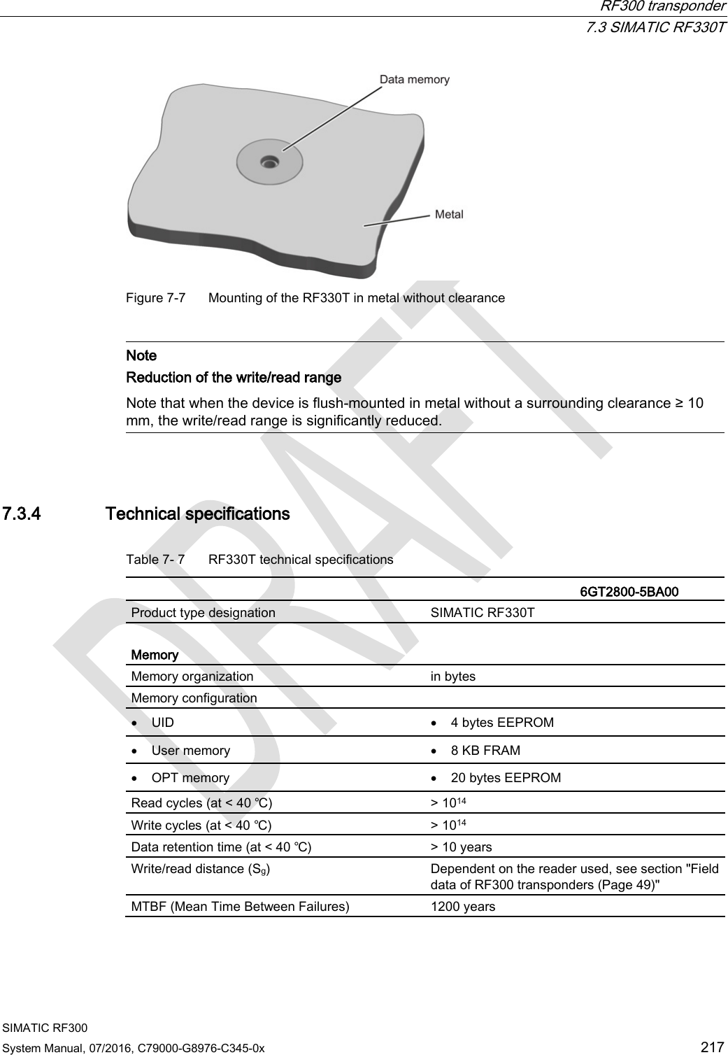
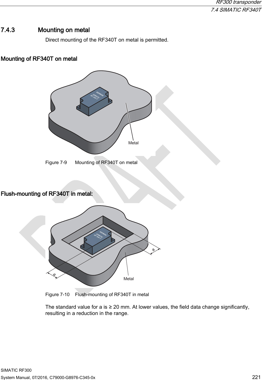
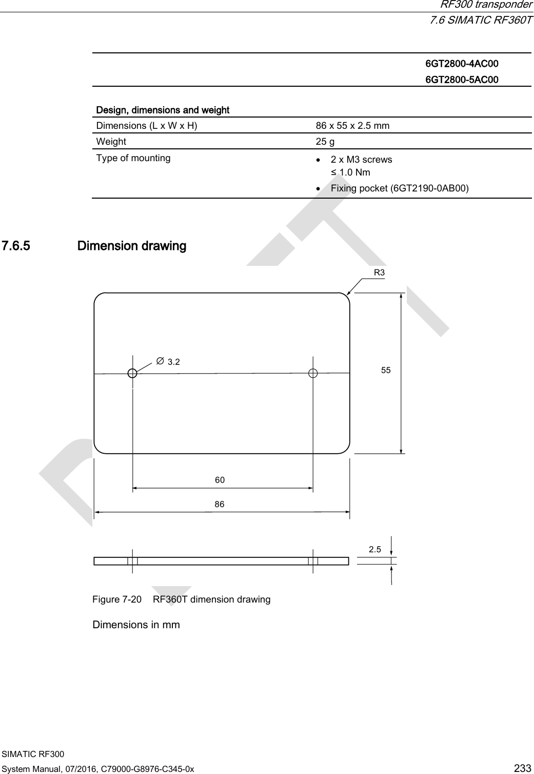
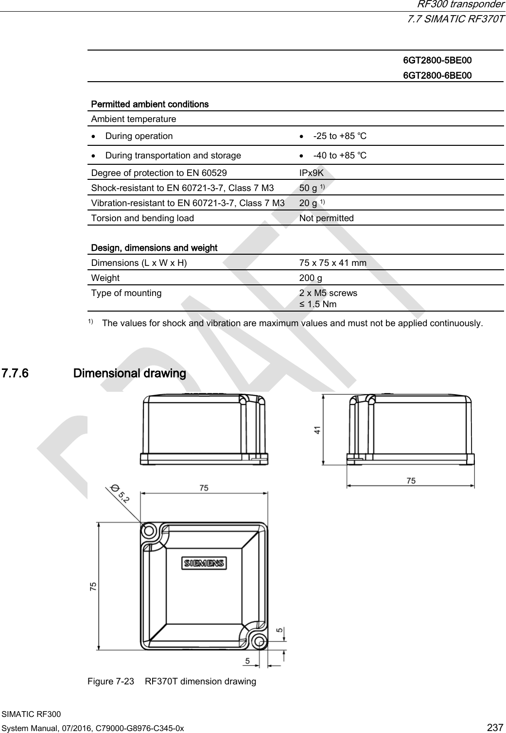
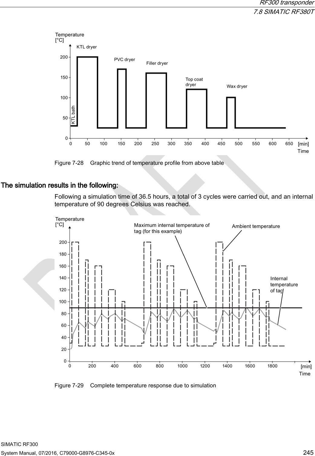
![System diagnostics 10.2 Diagnostics functions - STEP 7 Classic SIMATIC RF300 System Manual, 07/2016, C79000-G8976-C345-0x 401 10.2.3 Transponder diagnostics with MDS STATUS The MDS STATUS command can be used to scan the status and diagnostics data of the transponder that is located within the antenna field. MDS STATUS (mode 1), corresponds to UDT 260 (only for RF300 transponders) Name Type Possible Hex values Comment UID array[1…8] byte 000000005555555 ... 00000000FFFFFFFF Unique identifier = b0-31: 4 byte TAG ID, b32-63: 0 MDS_type byte 01 02 03 04 Transponder memory configuration = Transponder without FRAM = Transponder with FRAM 8 KB = Transponder with FRAM 32 KB = Transponder with FRAM 64 KB Lock_state byte 0 ... FF EEPROM write protection status MDS STATUS (mode 02), corresponds to UDT 270, only for RF300 transponders Name Type Possible Hex values Comment UID array[1…8] byte 0000000055555555 ... 00000000FFFFFFFF Unique identifier = b0-31: 4 byte TAG ID, b32-63: 0 LFD byte 0 ... FF = Value for field strength determined in the transponder FZP byte 0 ... FF = Error counter (passive) ➙ errors during idle time FZA byte 0 ... FF = Error counter (active) ANWZ byte 0 ... FF = Presence counter](https://usermanual.wiki/Siemens/RF340R02.User-Manual-part-2/User-Guide-3093595-Page-209.png)
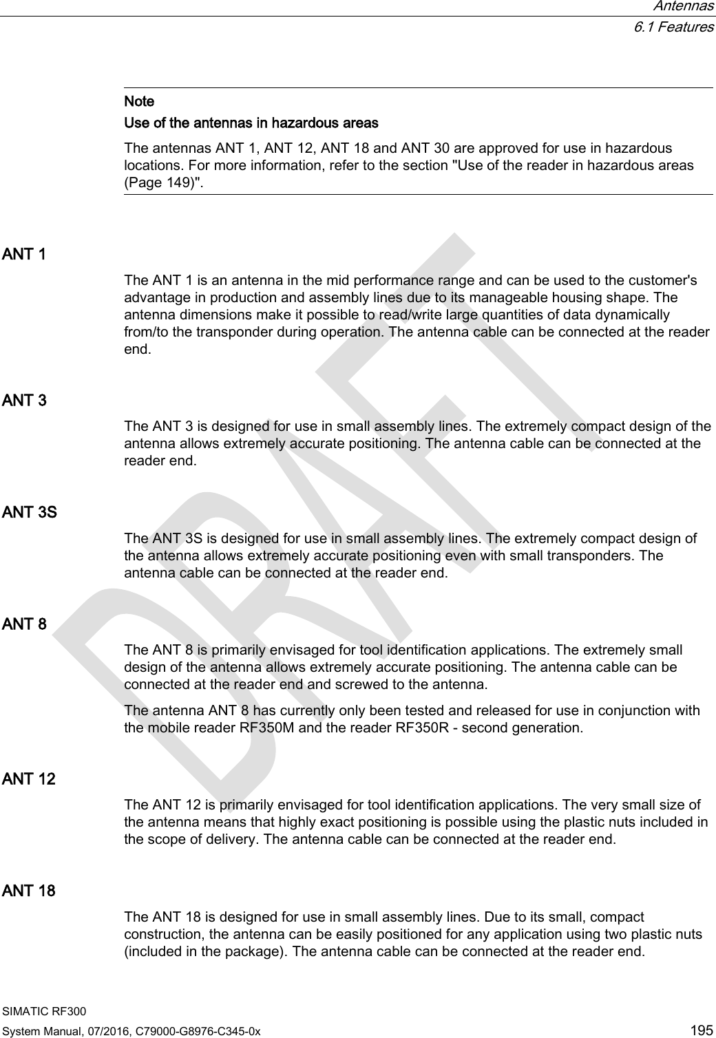
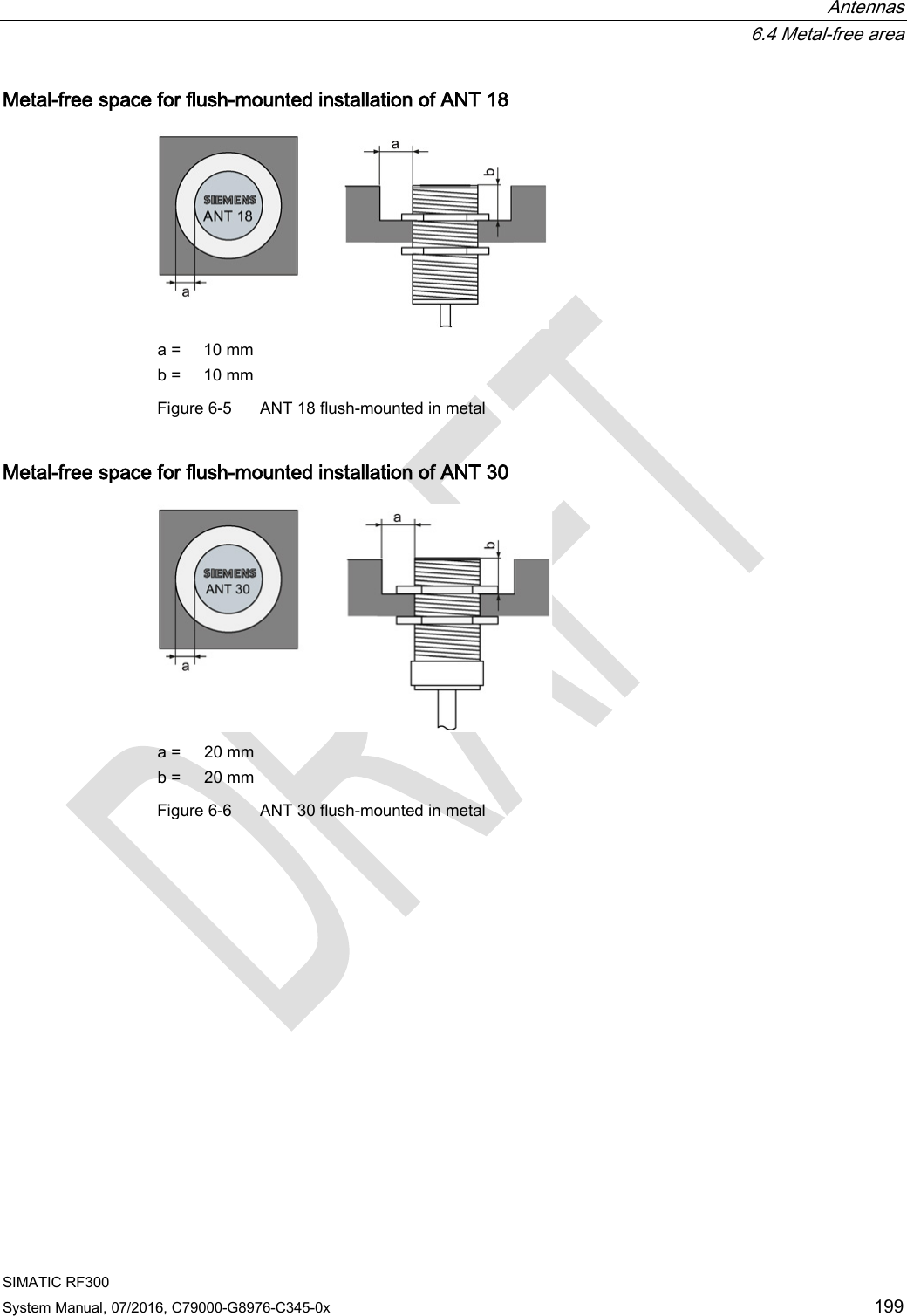
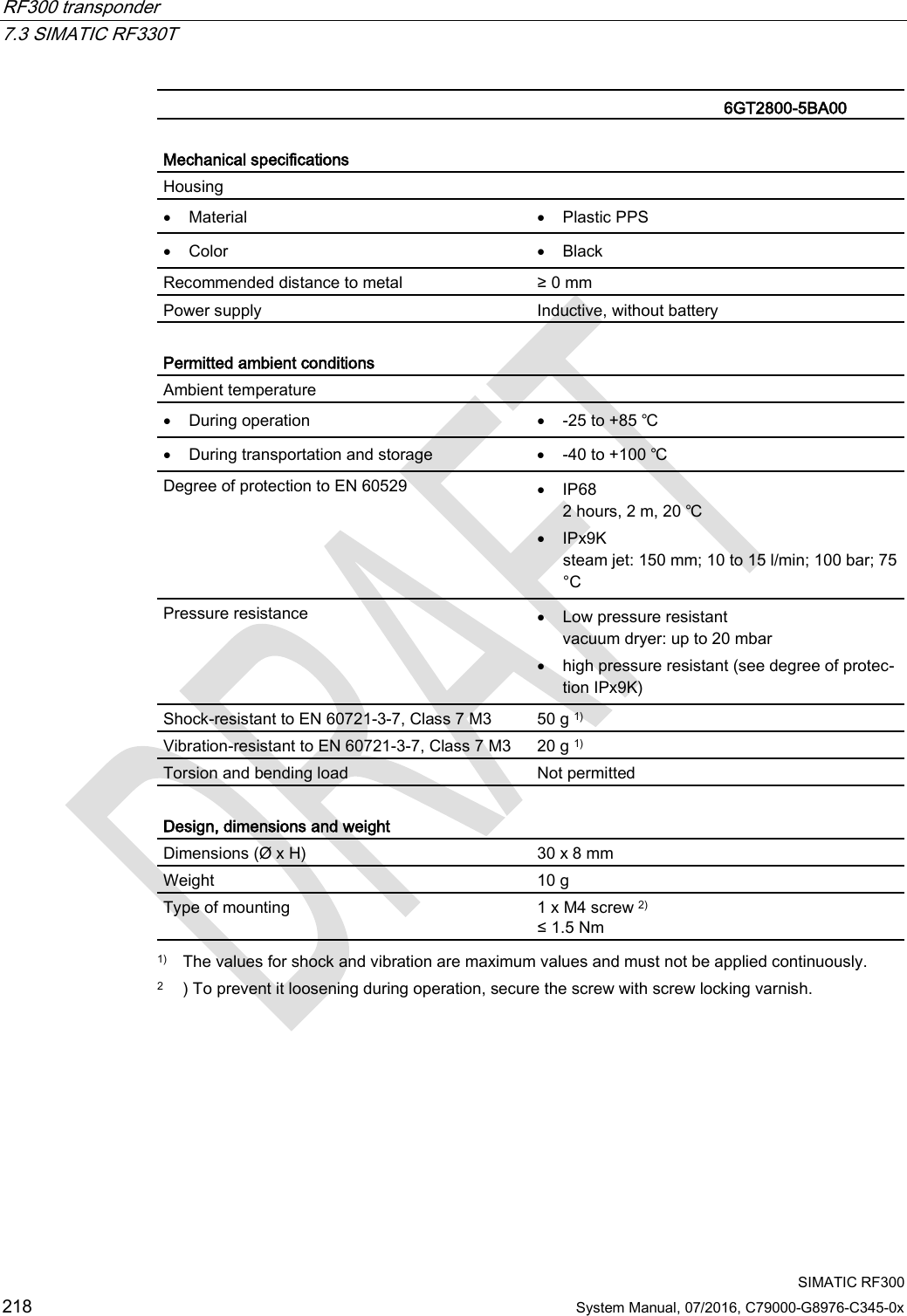
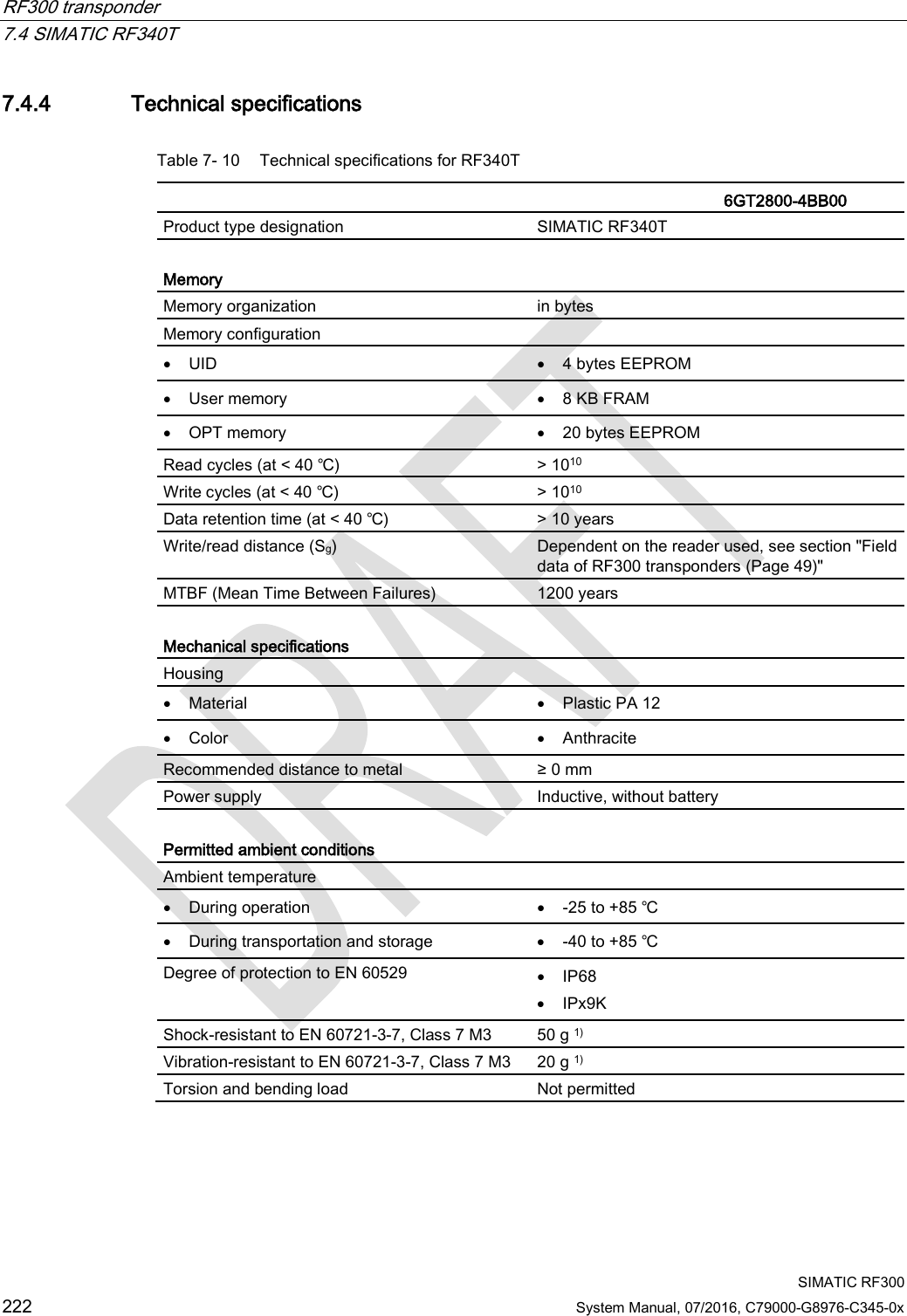
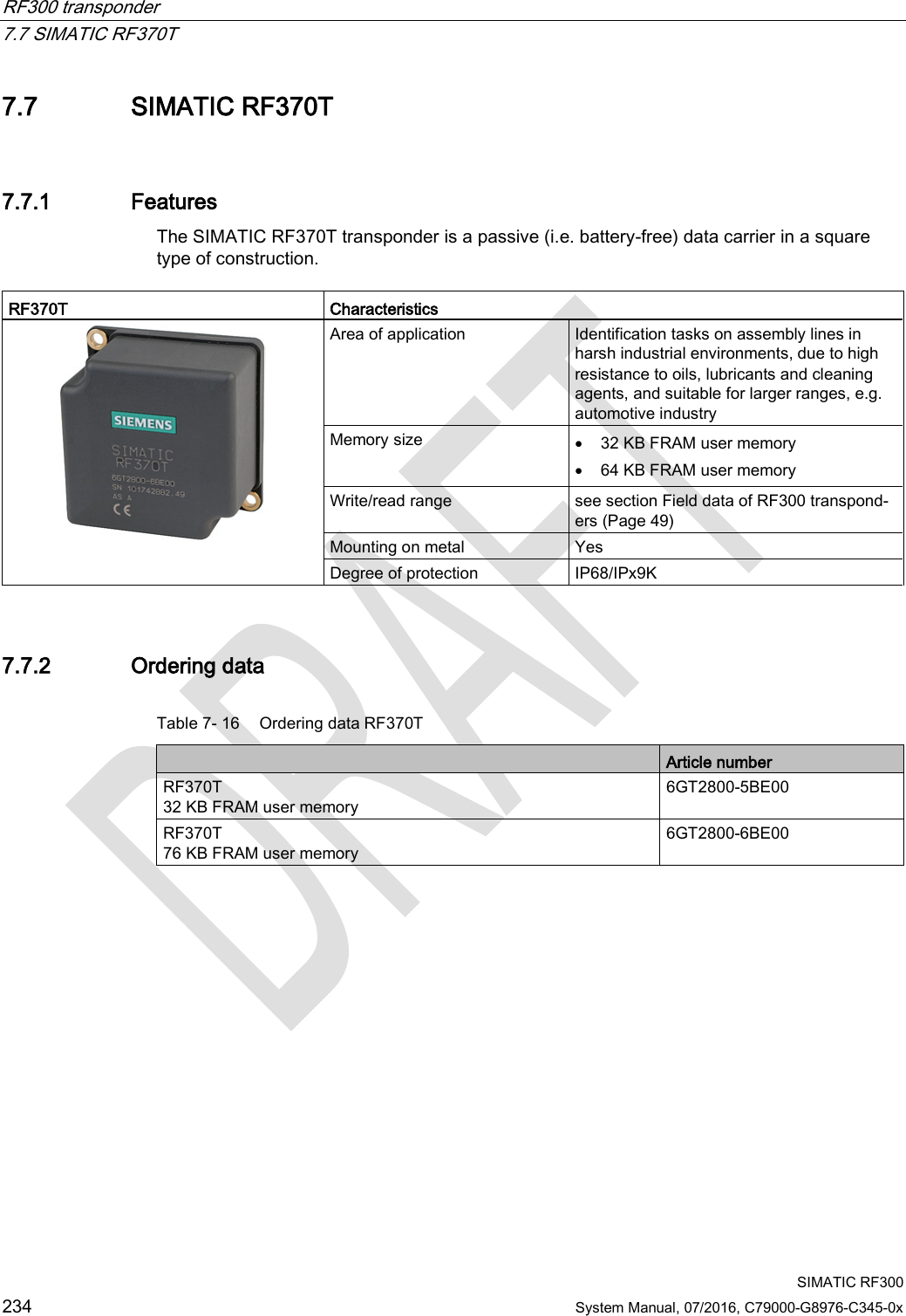
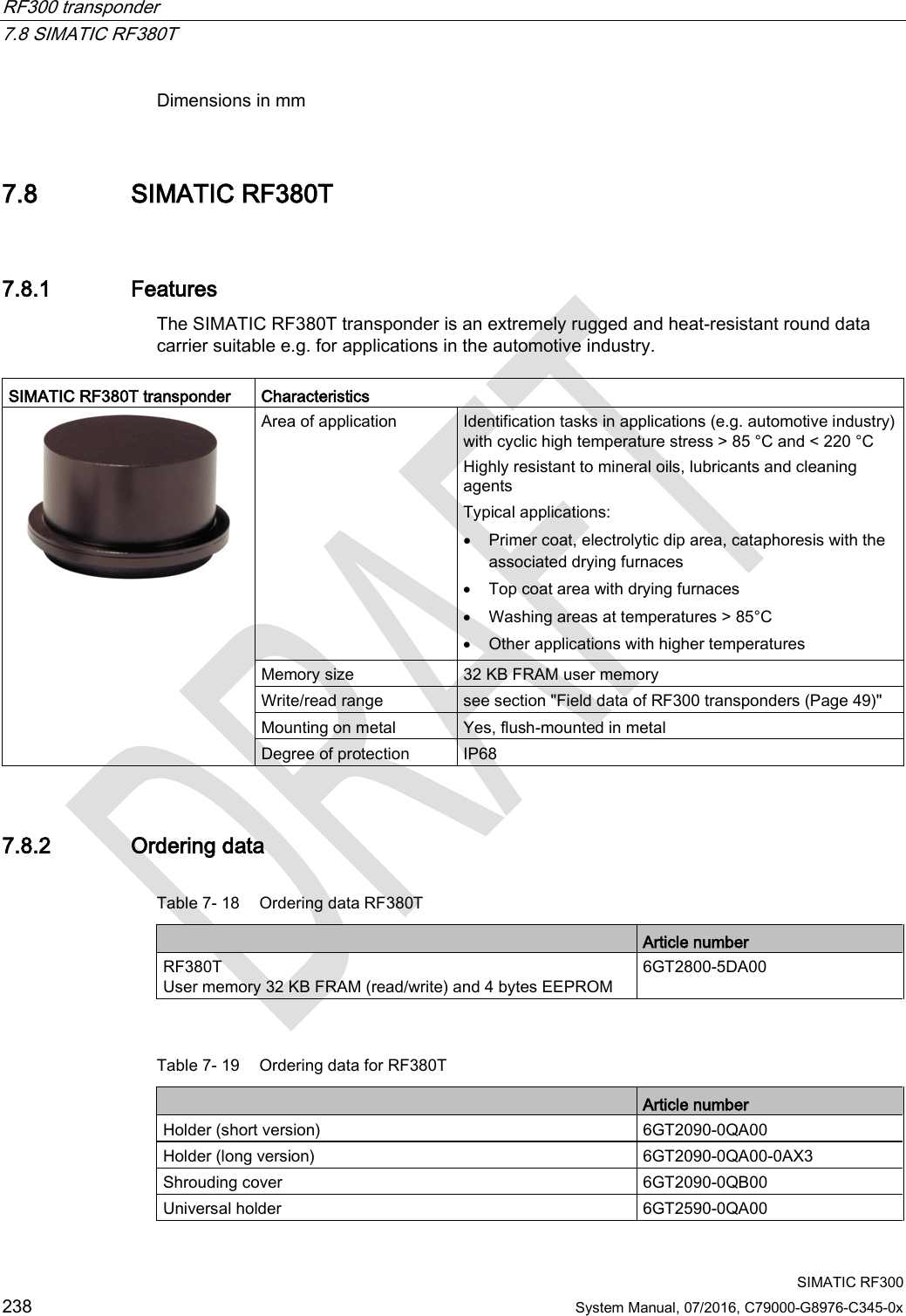
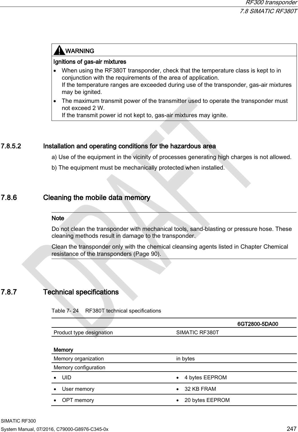
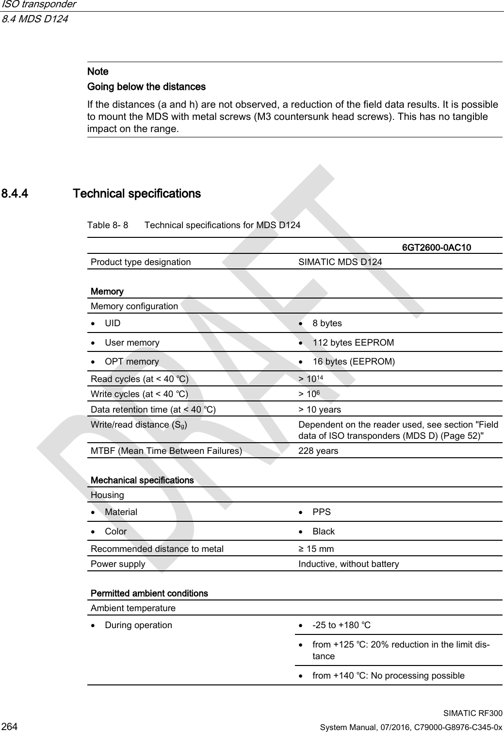
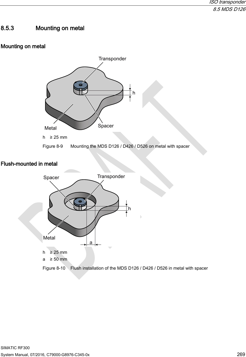
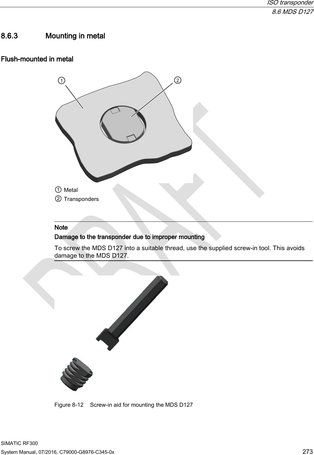
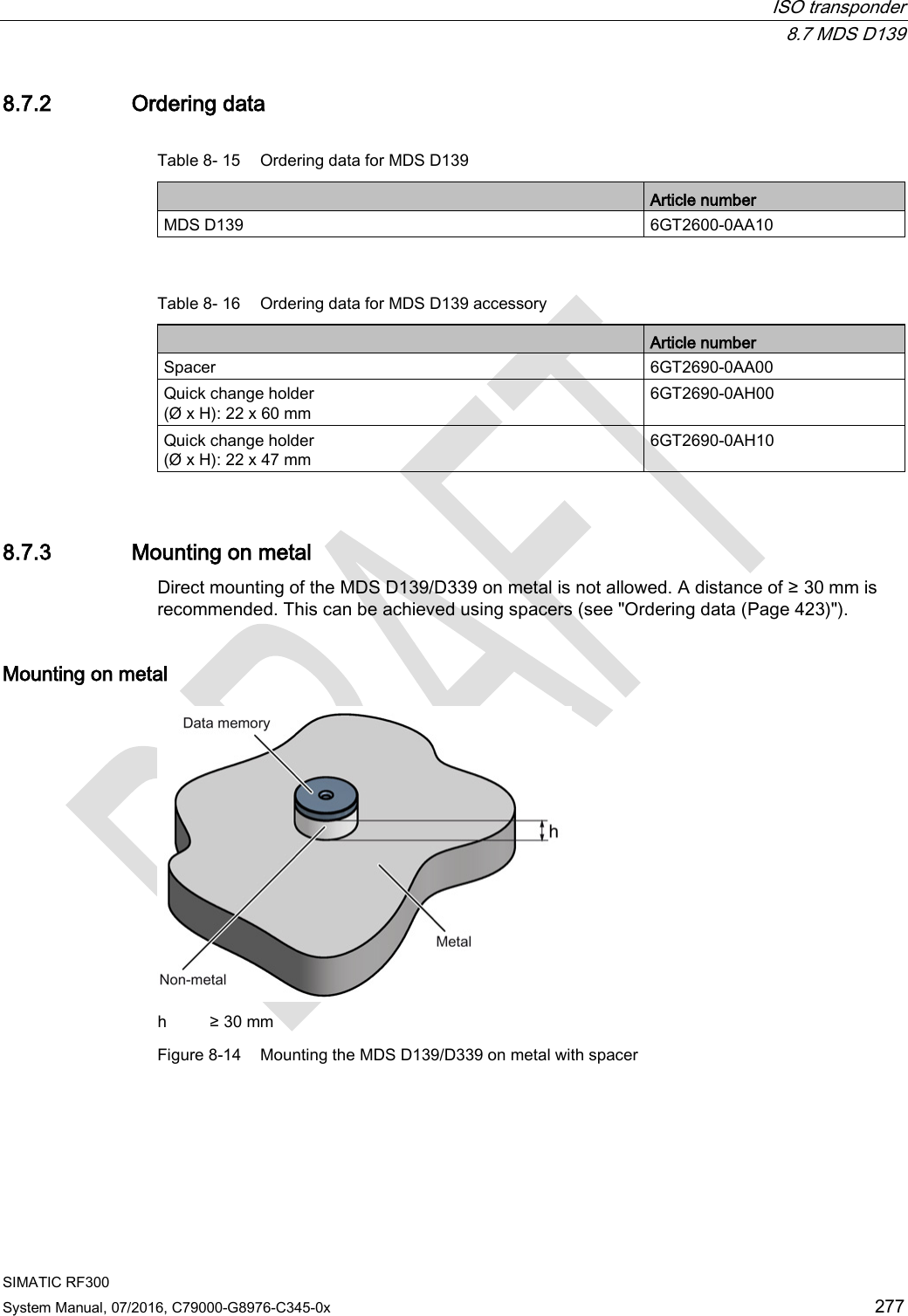
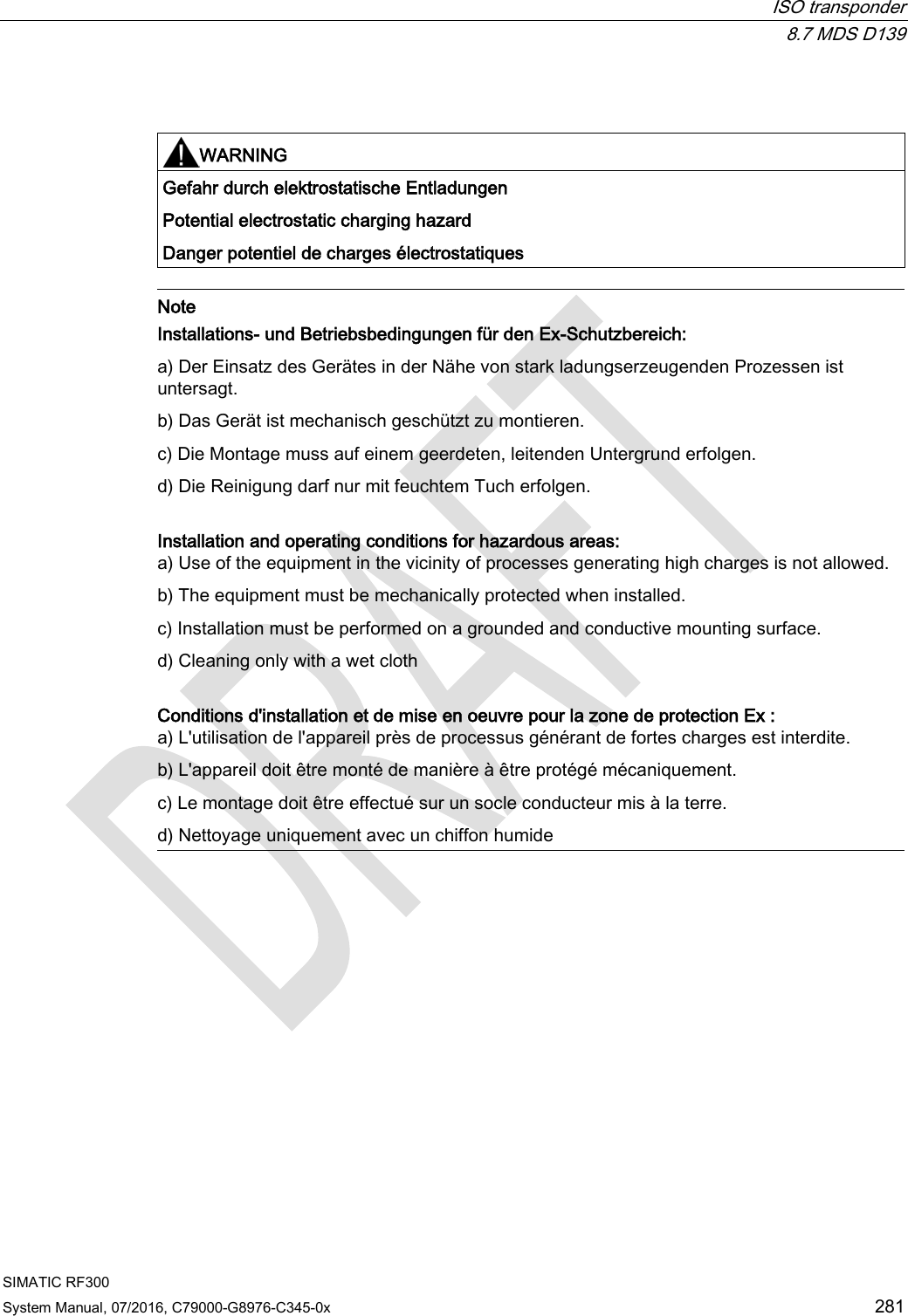
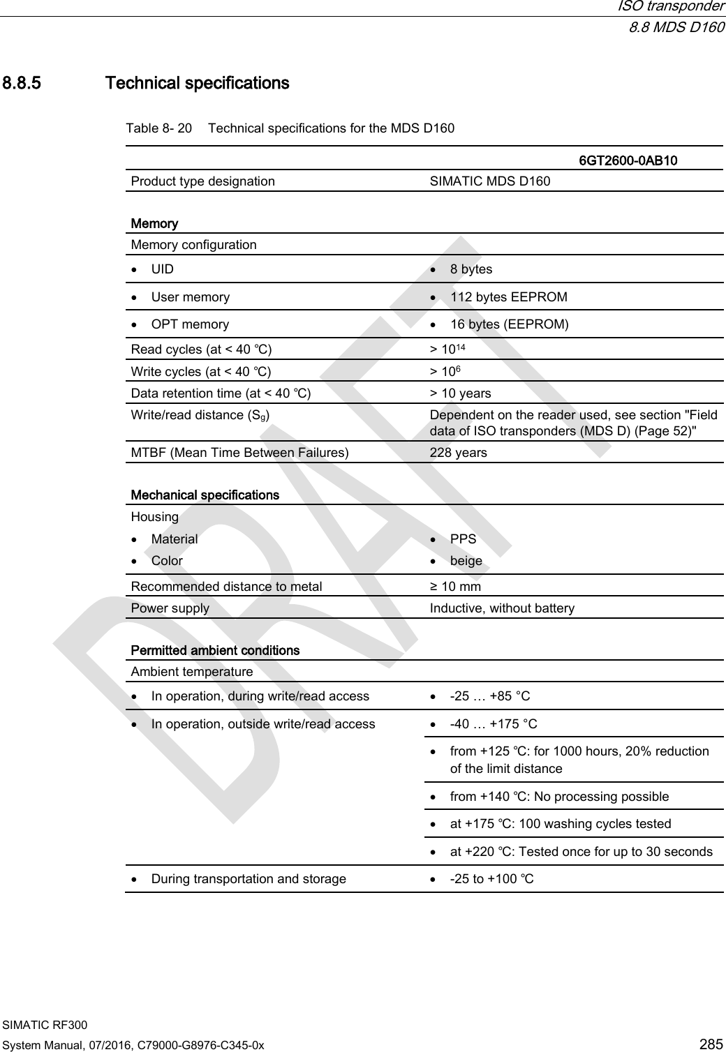
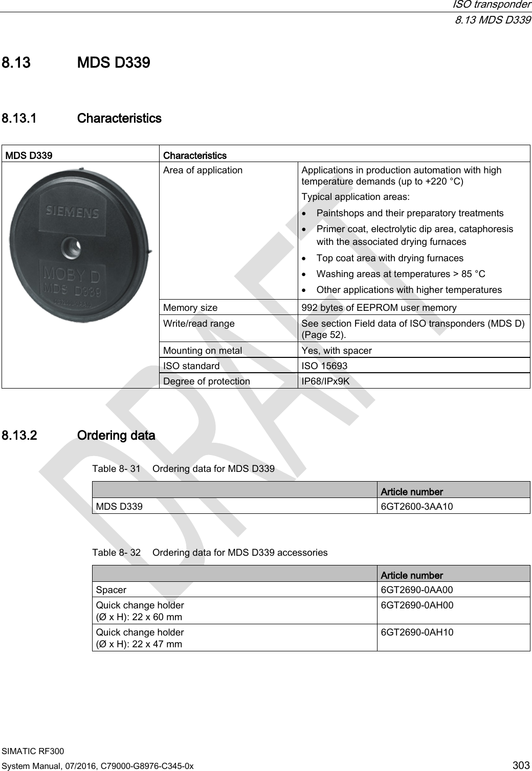
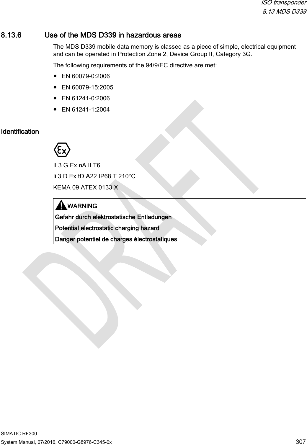
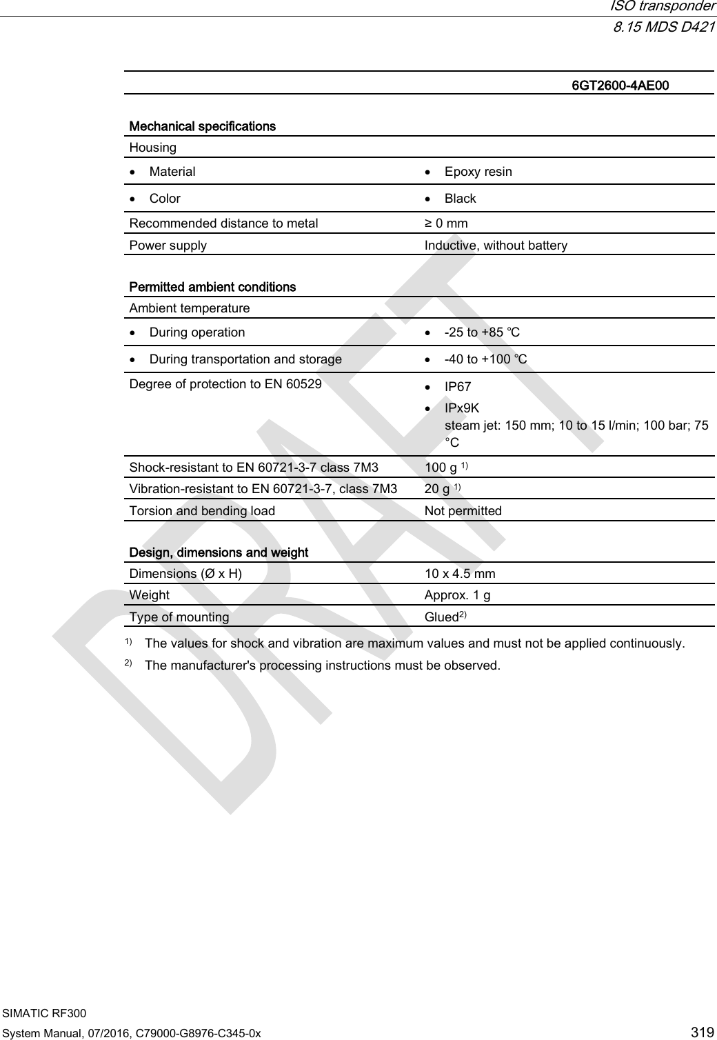
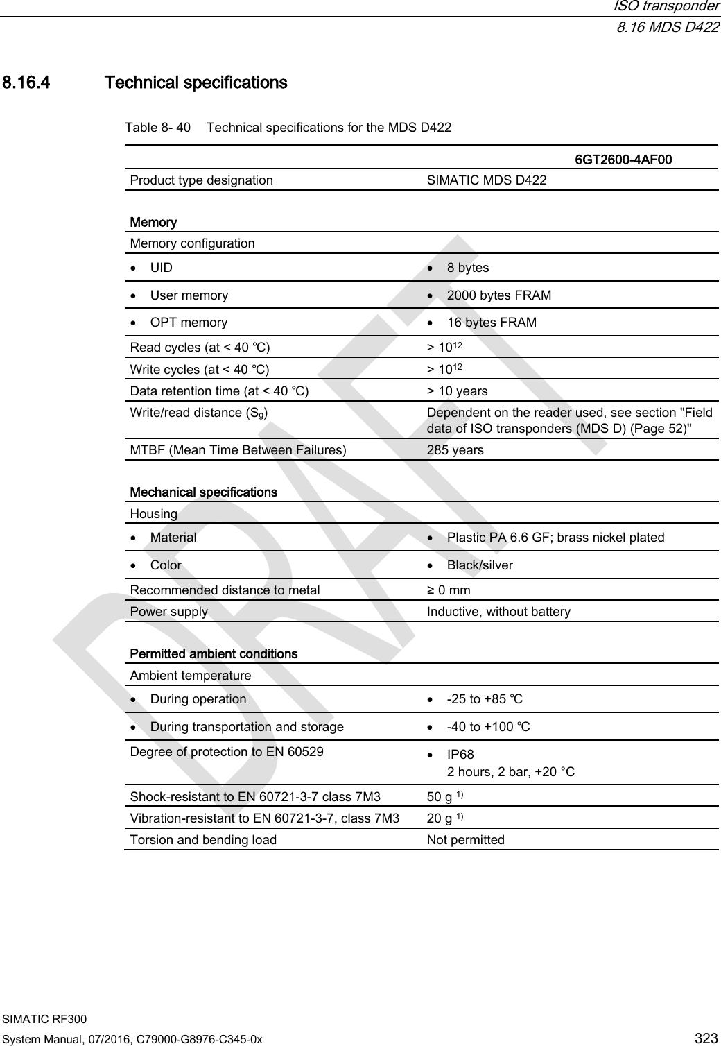
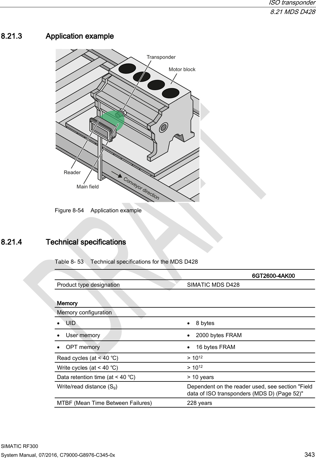
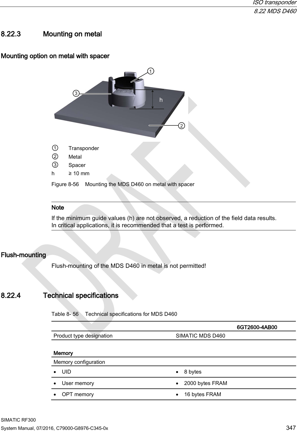
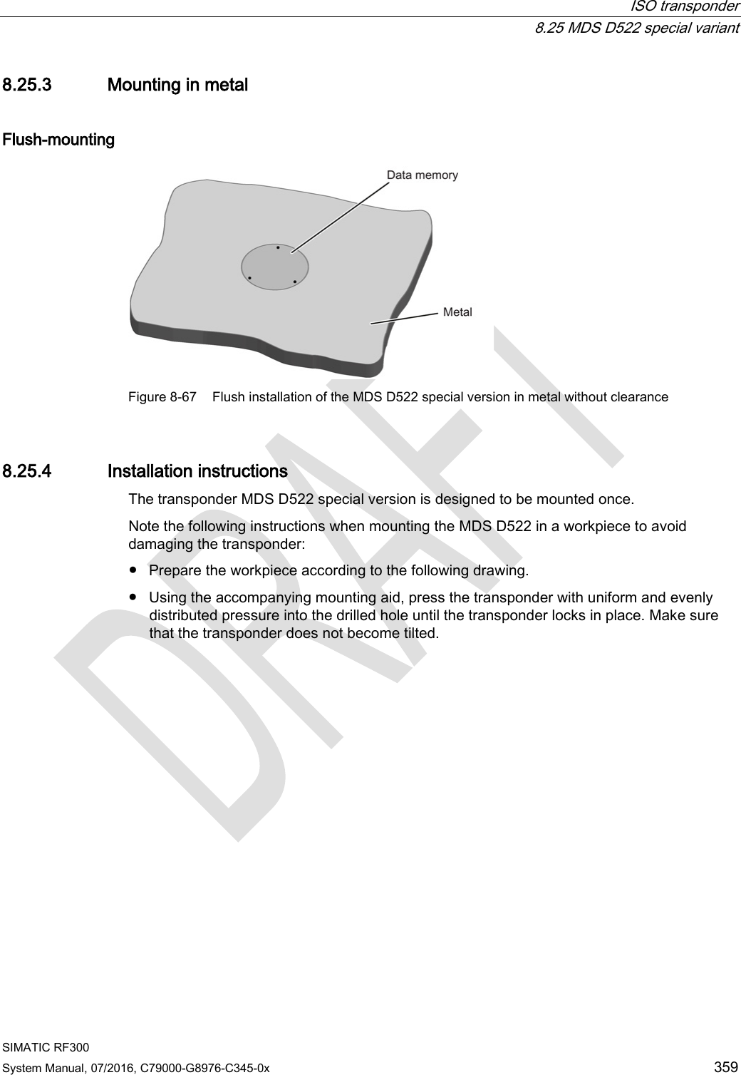
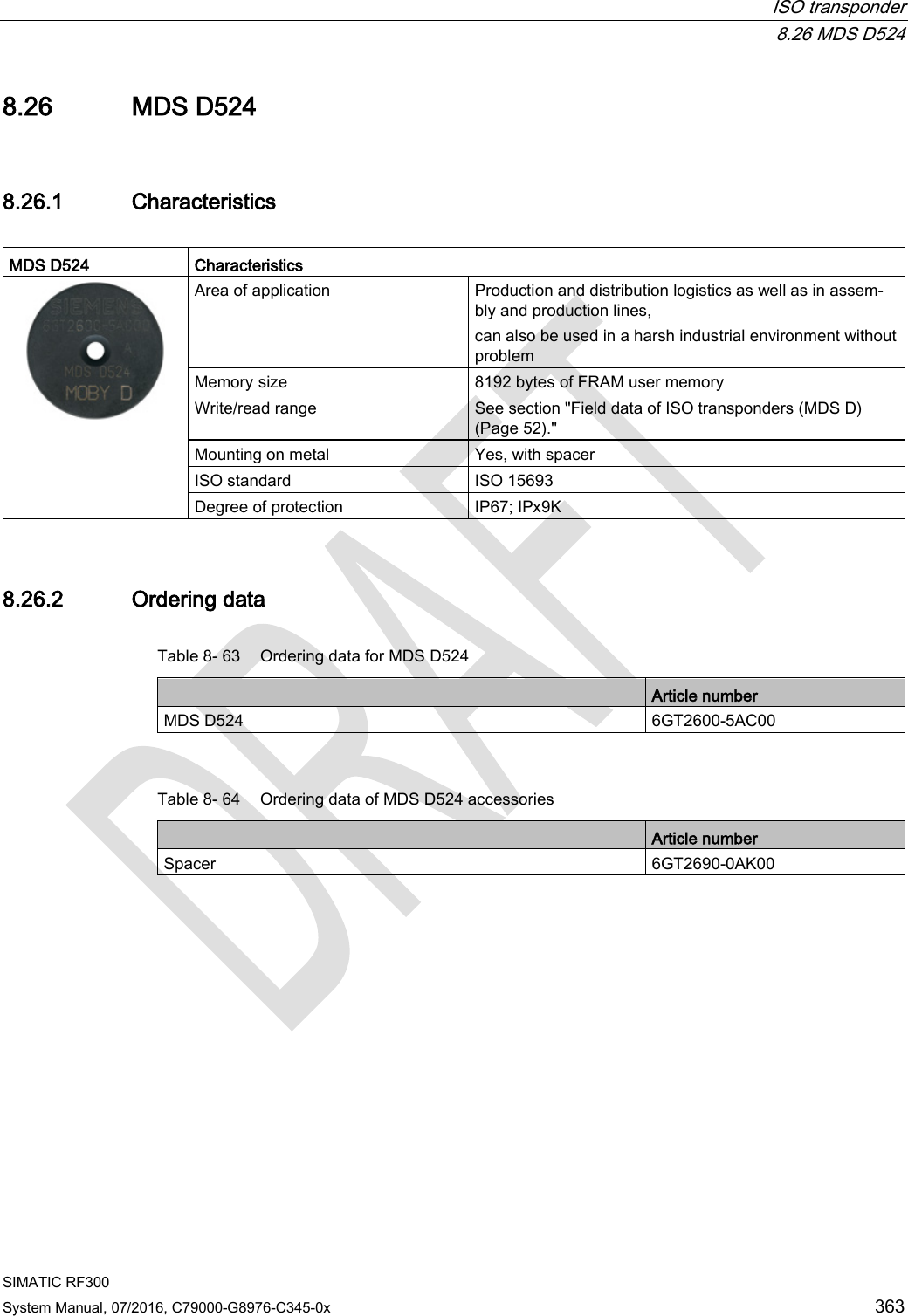
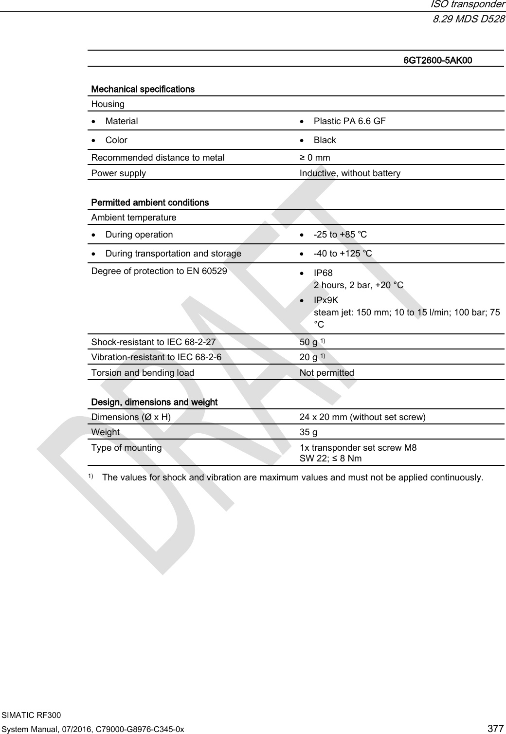
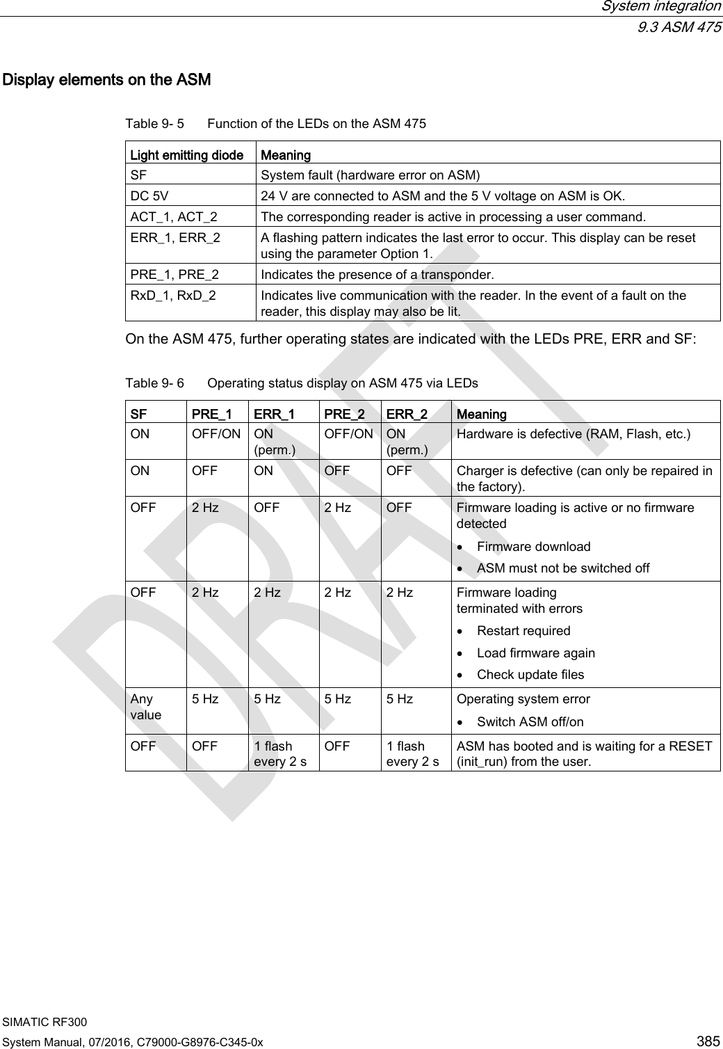
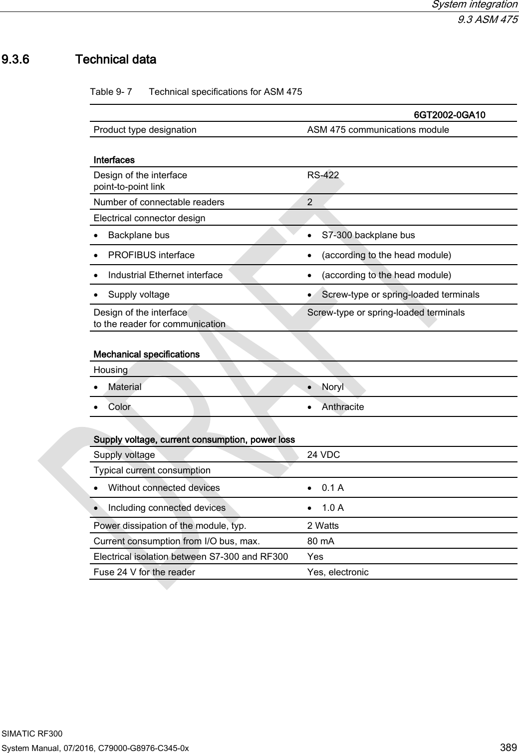
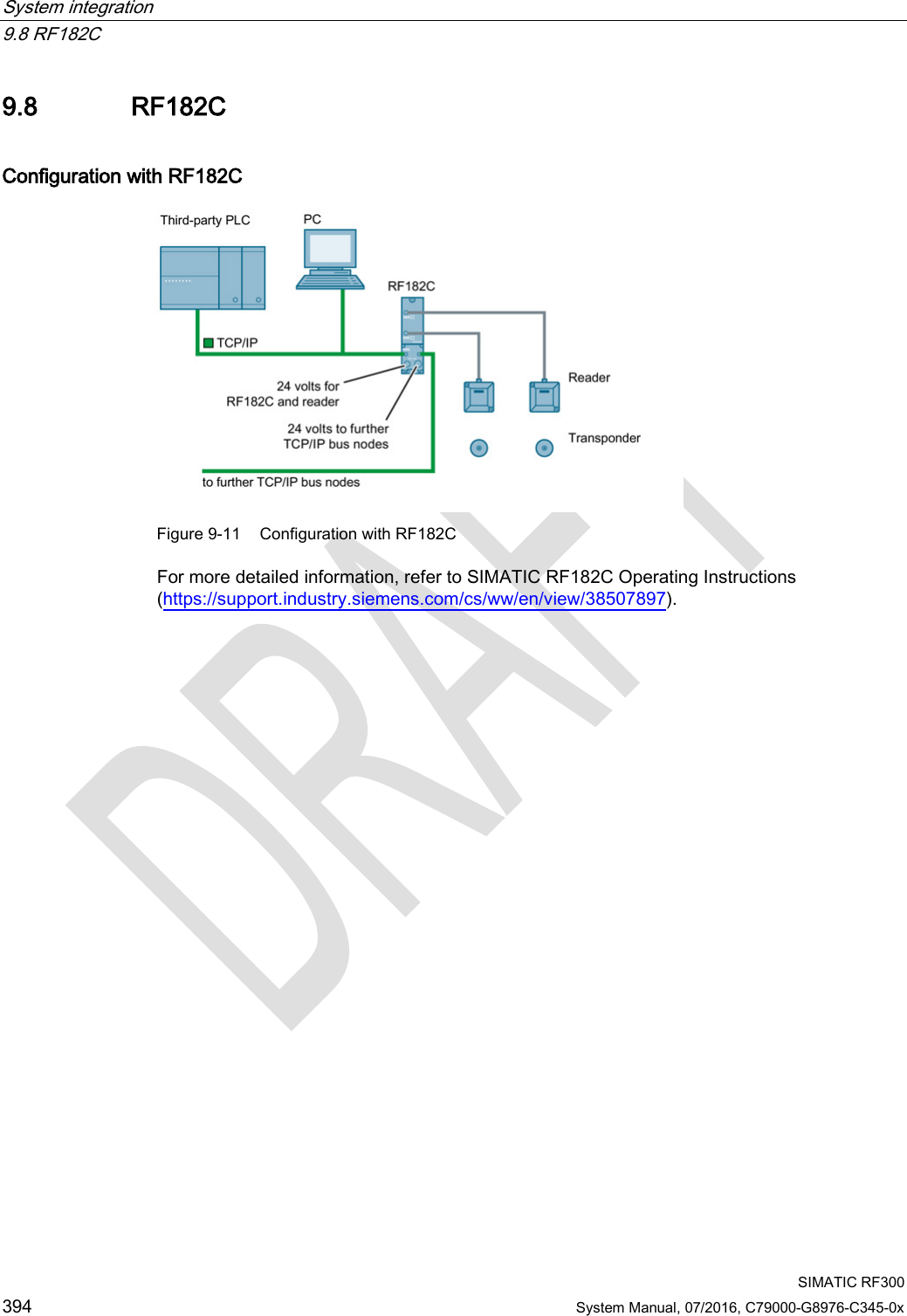
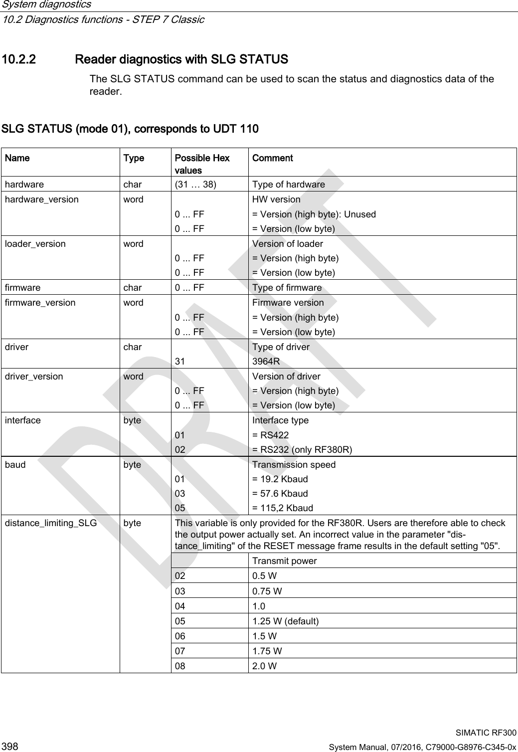
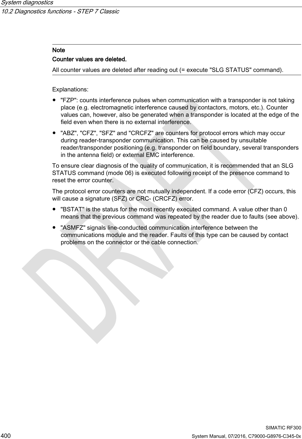
![System diagnostics 10.2 Diagnostics functions - STEP 7 Classic SIMATIC RF300 402 System Manual, 07/2016, C79000-G8976-C345-0x Note Counter values are deleted. All counter values are deleted when the transponder exits the antenna field or when the antenna is switched off. Explanations: ● "LFD" is a measured value for the field strength that is determined in the transponder. The lower the value, the higher the field strength. ● "FZP" counts interference pulses when communication with a transponder is not taking place (e.g. electromagnetic interference caused by contactors, motors, etc.). Counter values can also be generated when a transponder is located at the edge of the field even when there is no external interference. ● "FZA" counts errors that can occur during reader-to-transponder communication. This can be caused by unsuitable reader/transponder positioning (e.g. transponder on field boundary, several data carriers in the field) or external electromagnetic interference. ● "ANWZ" is the value for the time that the transponder remains in the field before the MDS STATUS command (mode 02) is executed. A time step is 10 ms. The maximum time that can be recorded is therefore 2.5 s. MDS STATUS (mode 03), corresponds to UDT 230 Name Type Possible Values Comment UID array[1…8] byte 0000000000000000 ... FFFFFFFFFFFFFFFF Unique identifier =8 byte UID, MSB first MDS_type byte 00 03 04 05 06 07 08 11 12 13 14 15 16 21 22 23 Transponder type (vendor, identification) = ISO transponder (non-specific) = ISO transponder (Infineon, MDS D300) = ISO transponder (Fujitsu, MDS D400) = ISO transponder (Philips, MDS D100) = ISO transponder (Texas Instruments, MDS D200) = ISO transponder (ST, LRI2K) = ISO transponder (Fujitsu, MDS D500) = RF300 transponder (0 kB) = RF300 transponder (8 kB) = RF300 transponder (32 kB) = RF300 transponder (64 kB) = RF300 transponder (128 kB) = RF300 transponder (256 kB) = ISO transponder (NXP, 1 kB, MDS E) = ISO transponder (Infineon, 1 kB, MDS E) = ISO transponder (NXP, 4 kB)](https://usermanual.wiki/Siemens/RF340R02.User-Manual-part-2/User-Guide-3093595-Page-210.png)