Siemens RF350R Inductive Tag Reader User Manual RFID Systeme SIMATIC RF300
Siemens AG Inductive Tag Reader RFID Systeme SIMATIC RF300
UserManual.wiki
>
Siemens
>
RF350R User Manual
>
Manual Part 1
Contents
1.
Manual Part 1
2.
Manual Part 2
3.
Manual Part 3
Manual Part 1
Navigation menu
Upload a User Manual
Namespaces
Wiki Guide
HTML
PDF
Info
Views
User Manual
Discussion / Help
Navigation
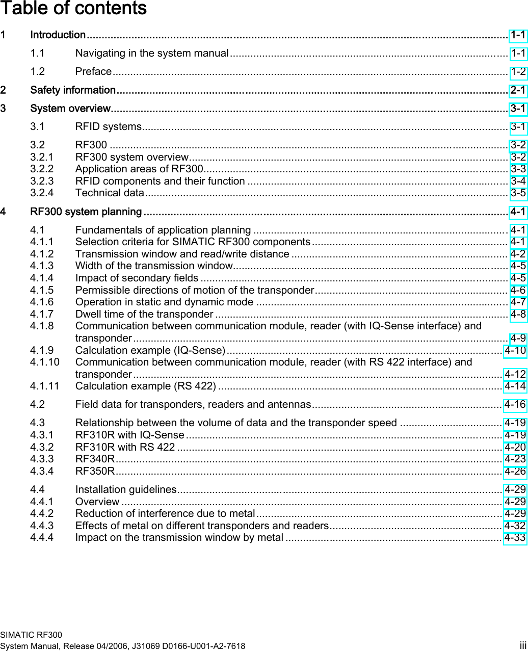
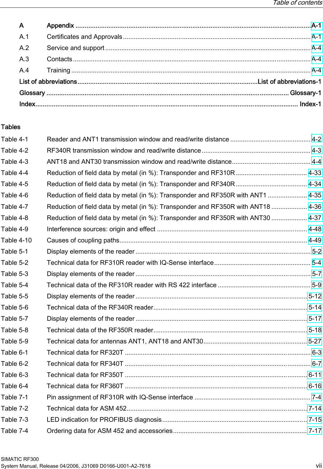
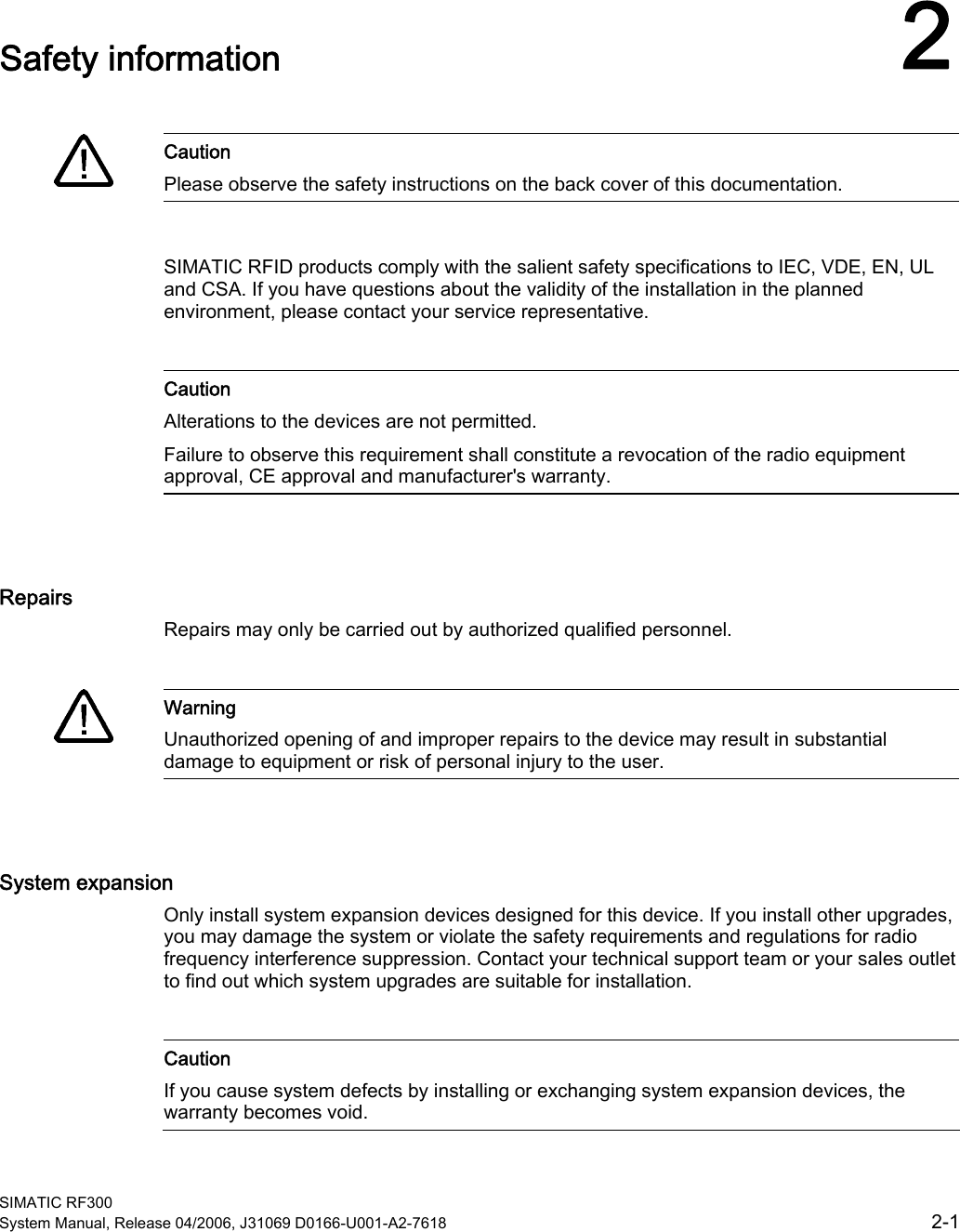

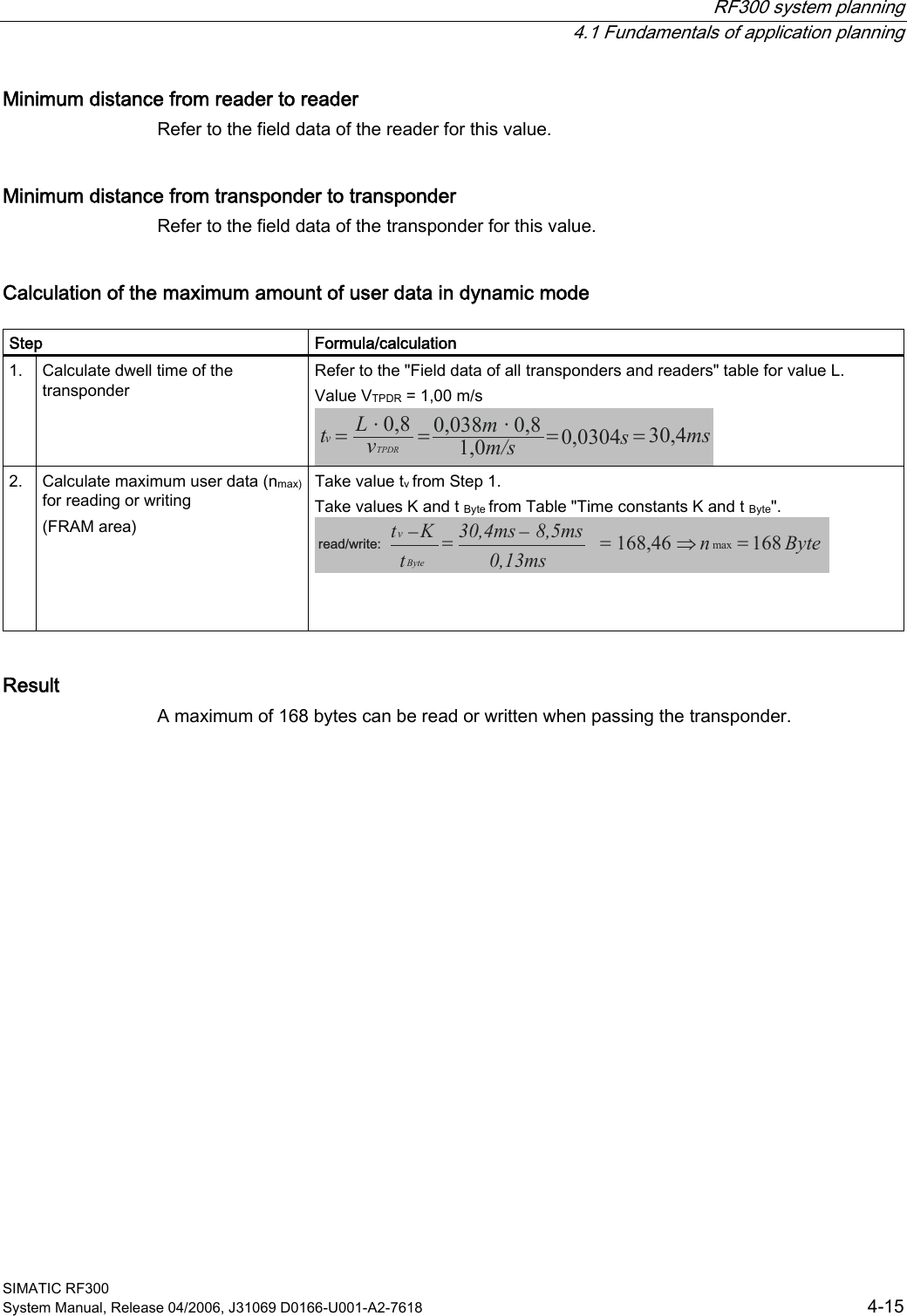
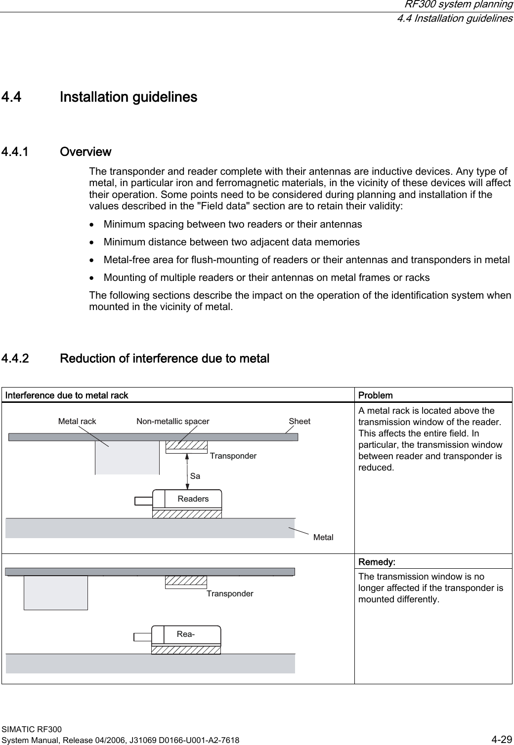
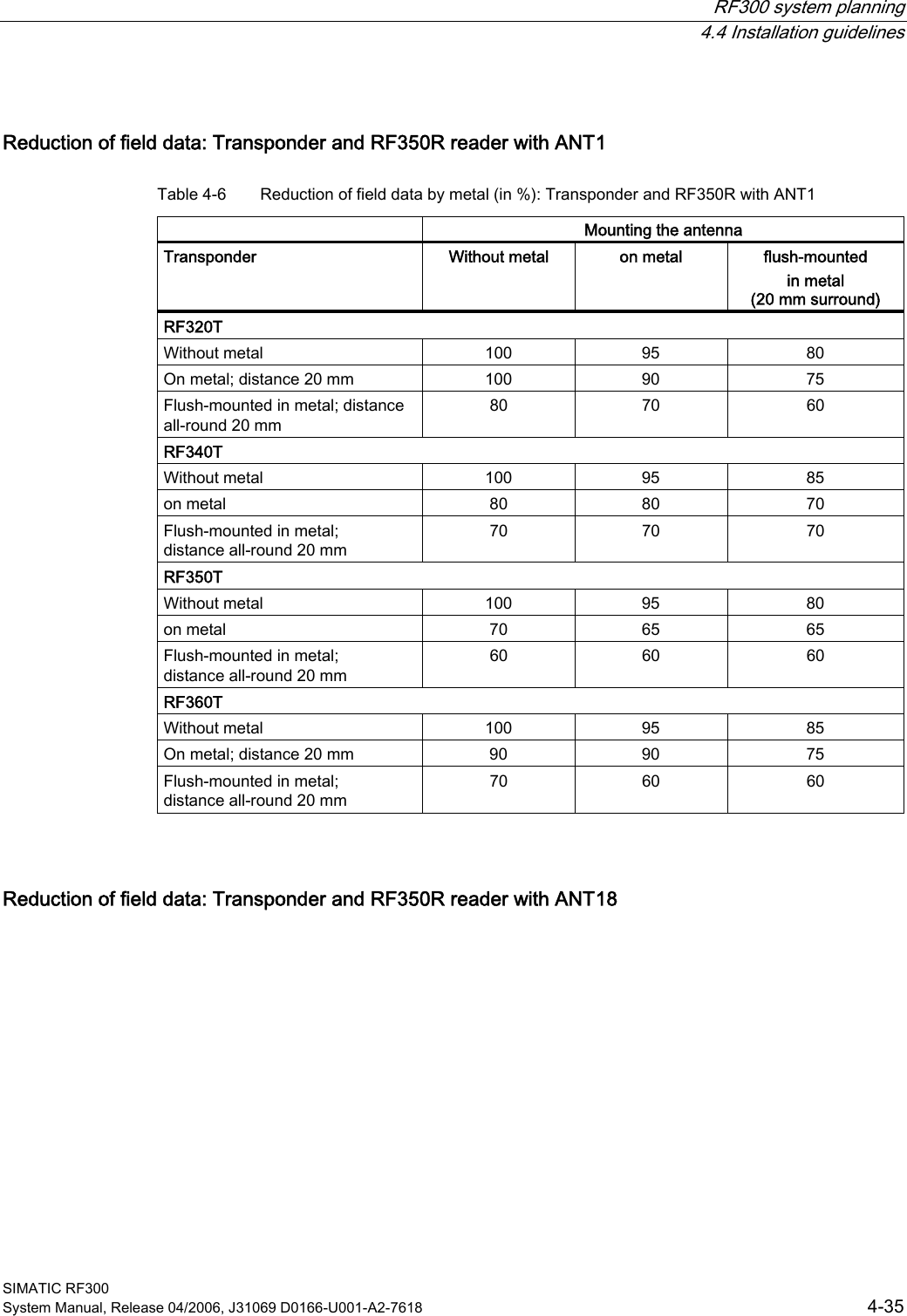
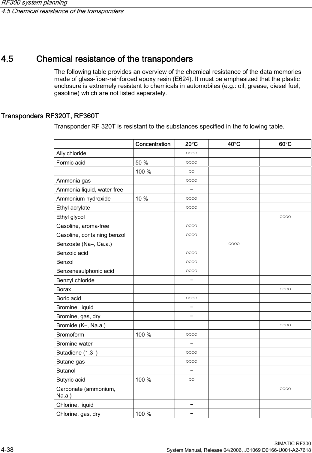
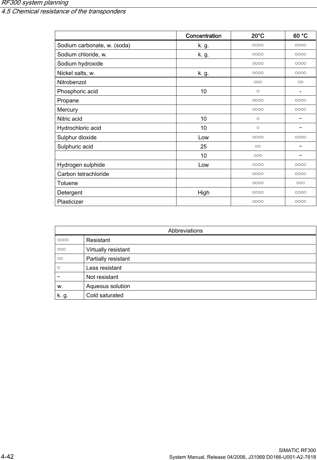
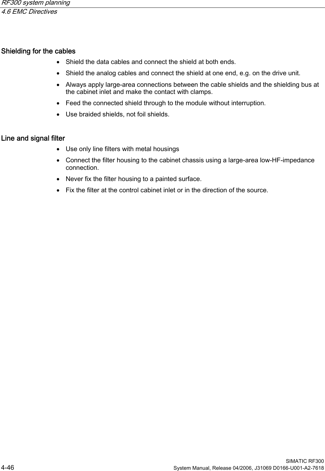
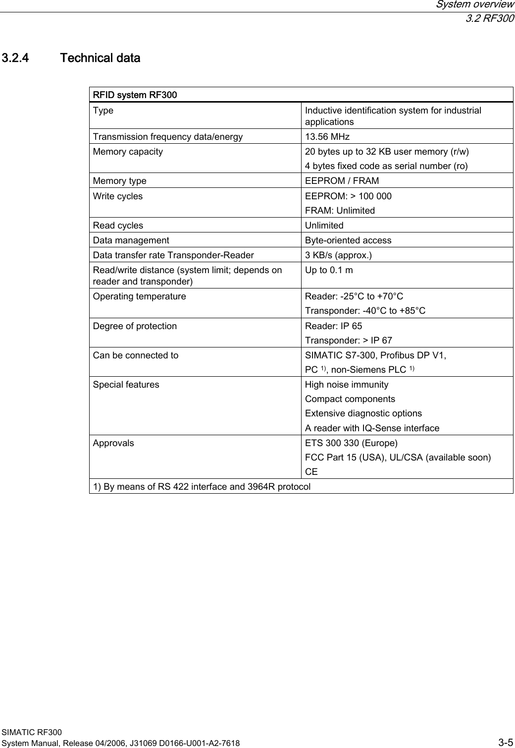
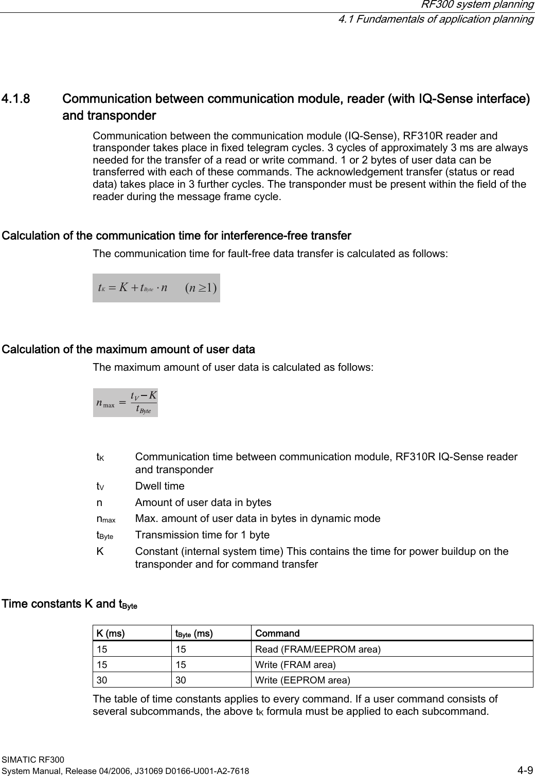
![System overview 3.2 RF300 SIMATIC RF300 3-4 System Manual, Release 04/2006, J31069 D0166-U001-A2-7618 3.2.3 RFID components and their function RF300 system components 6HULDODV\QFKURQRXVLQWHUIDFH565)7 5)73RZHUDQGGDWDWUDQVPLVVLRQ0+]5)5,46HQVH,46HQVHLQWHUIDFH[,46HQVHIRU(70RQ6ZLWK)&3&LQWHUIDFHWKLUGSDUW\3/&$60IRU6,0$7,&6$60IRU(7;DQG)&$60IRU352),%86'395)7 5)75)5 5)5 5)5$60bIRU352),%86'3'39 Communication modules A communication module (interface module) is used to integrate the RF identification system in PLC/automation systems. Reader The reader (read/write device) ensures inductive communication, supplies power to the transponder, and handles the connection to the various PLCs (e.g. SIMATIC S7) through the communication module (e.g. ASM 475). Transponder The transponder (data memory) stores all data relevant to the production process and is used, for example, instead of barcode. Conventions The RF310R and RF340R readers are equipped with an integral antenna, whereas the RF350R reader is operated over an external antenna. In this system manual, the term "Reader" is used throughout even where it is actually referring to the antenna of the reader.](https://usermanual.wiki/Siemens/RF350R.Manual-Part-1/User-Guide-674261-Page-18.png)
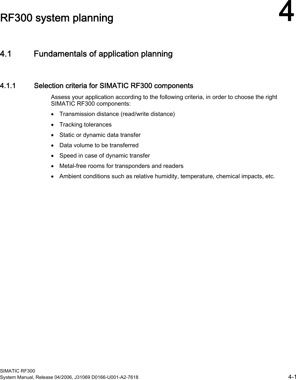
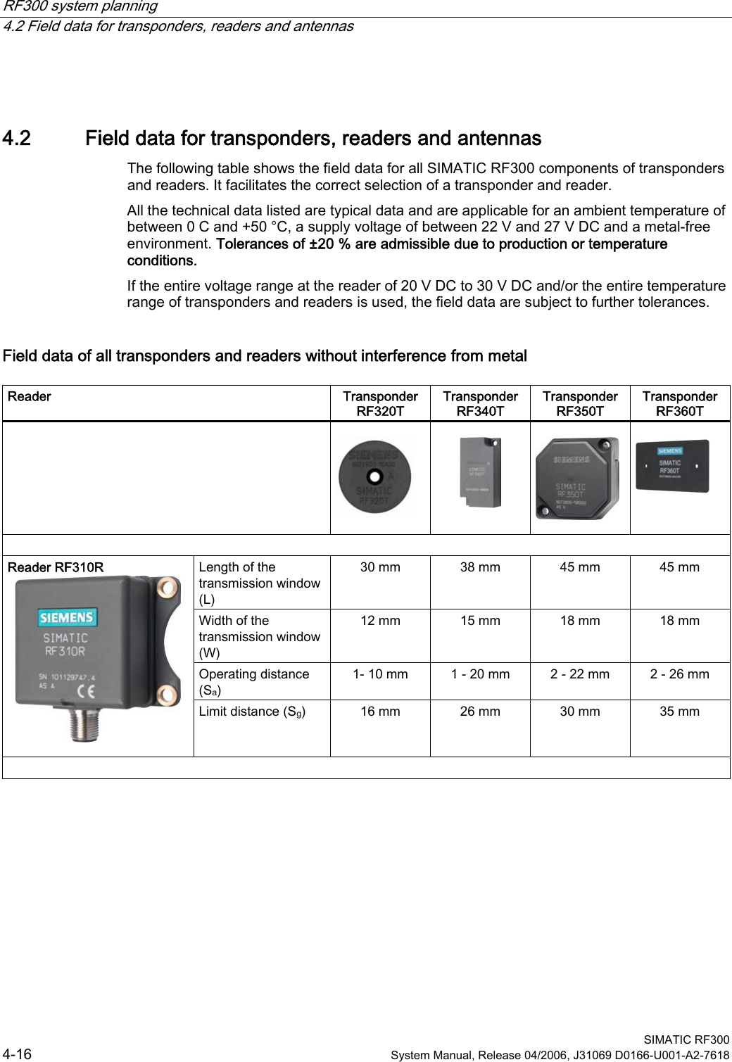
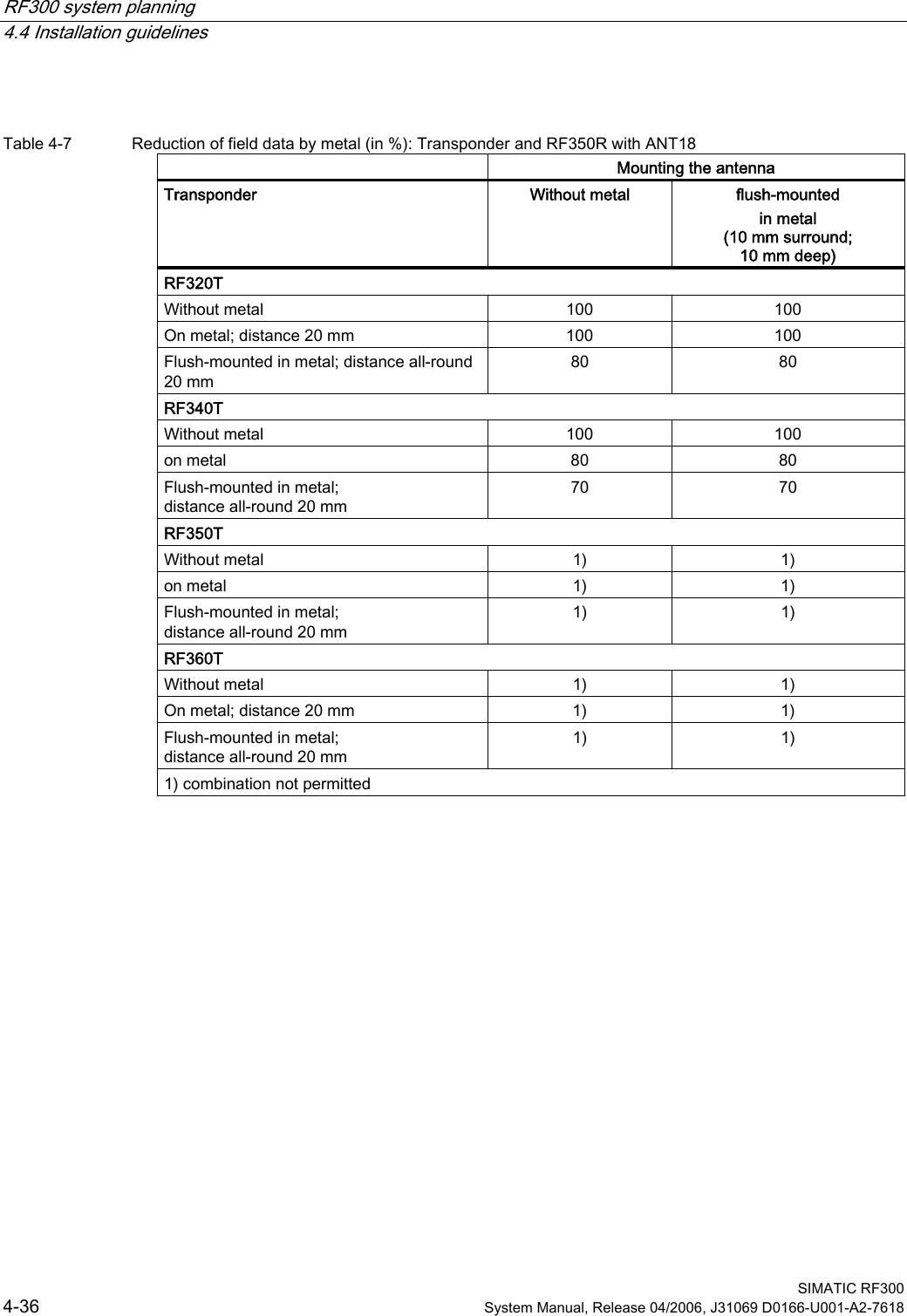
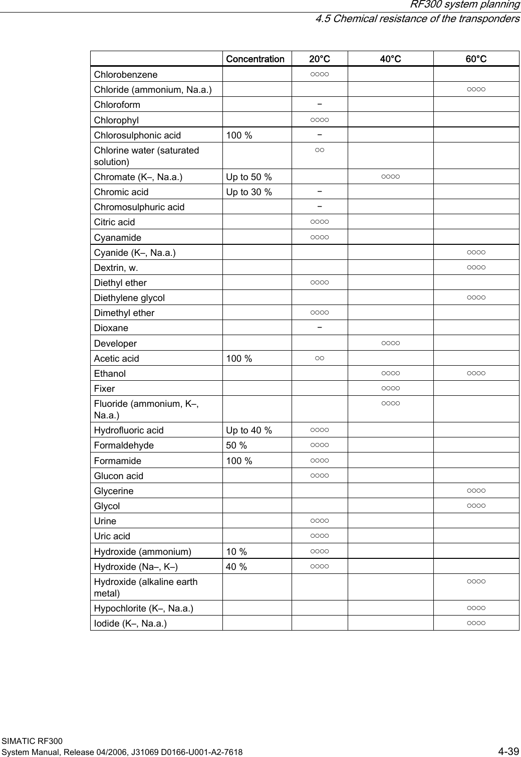
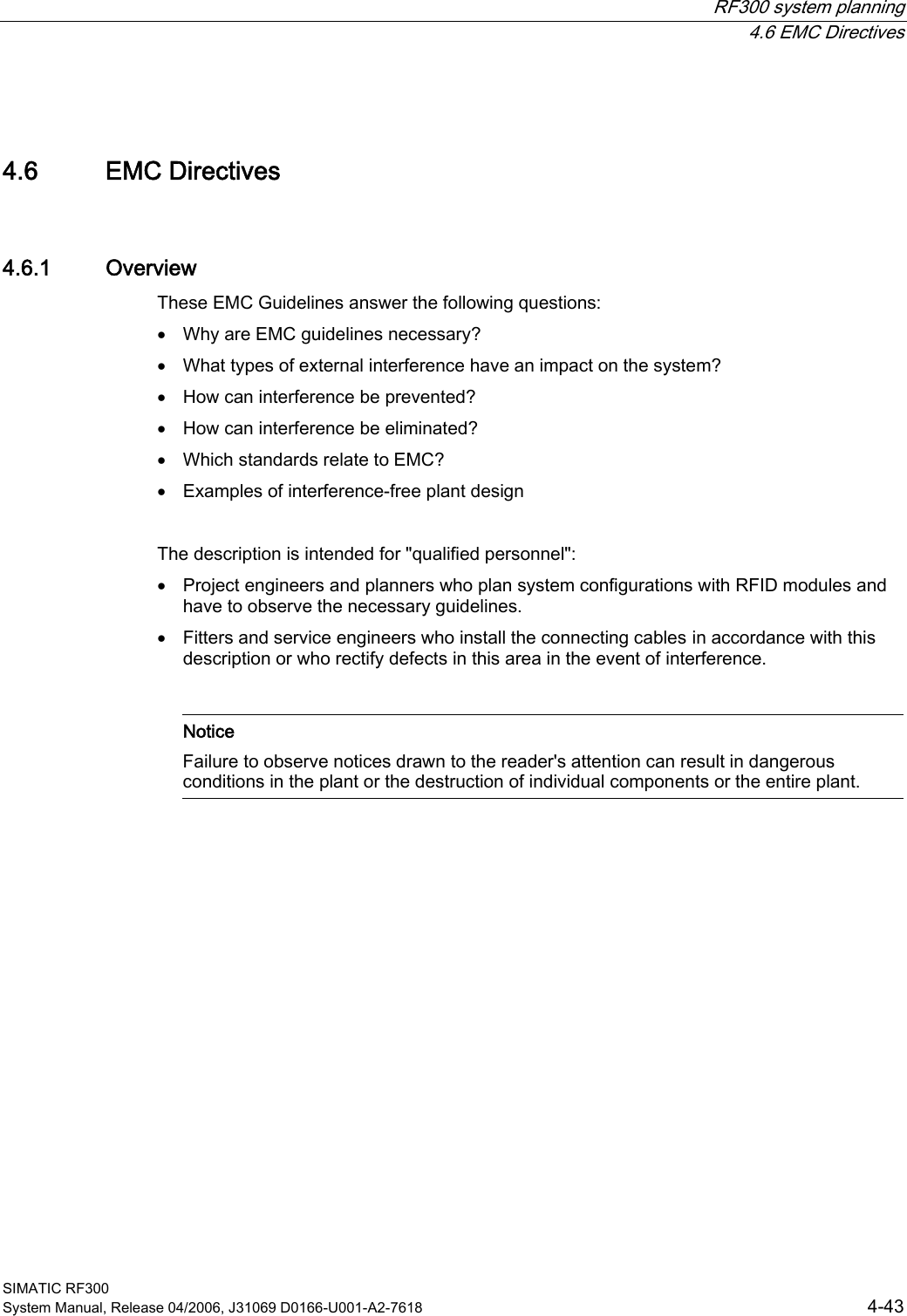
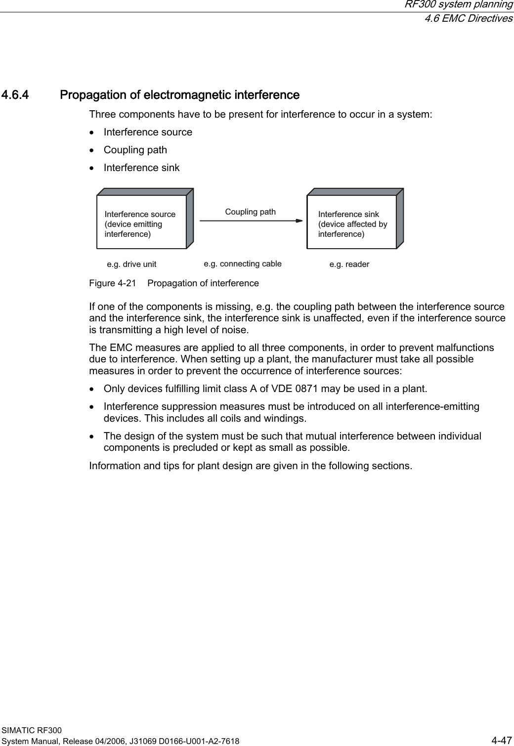
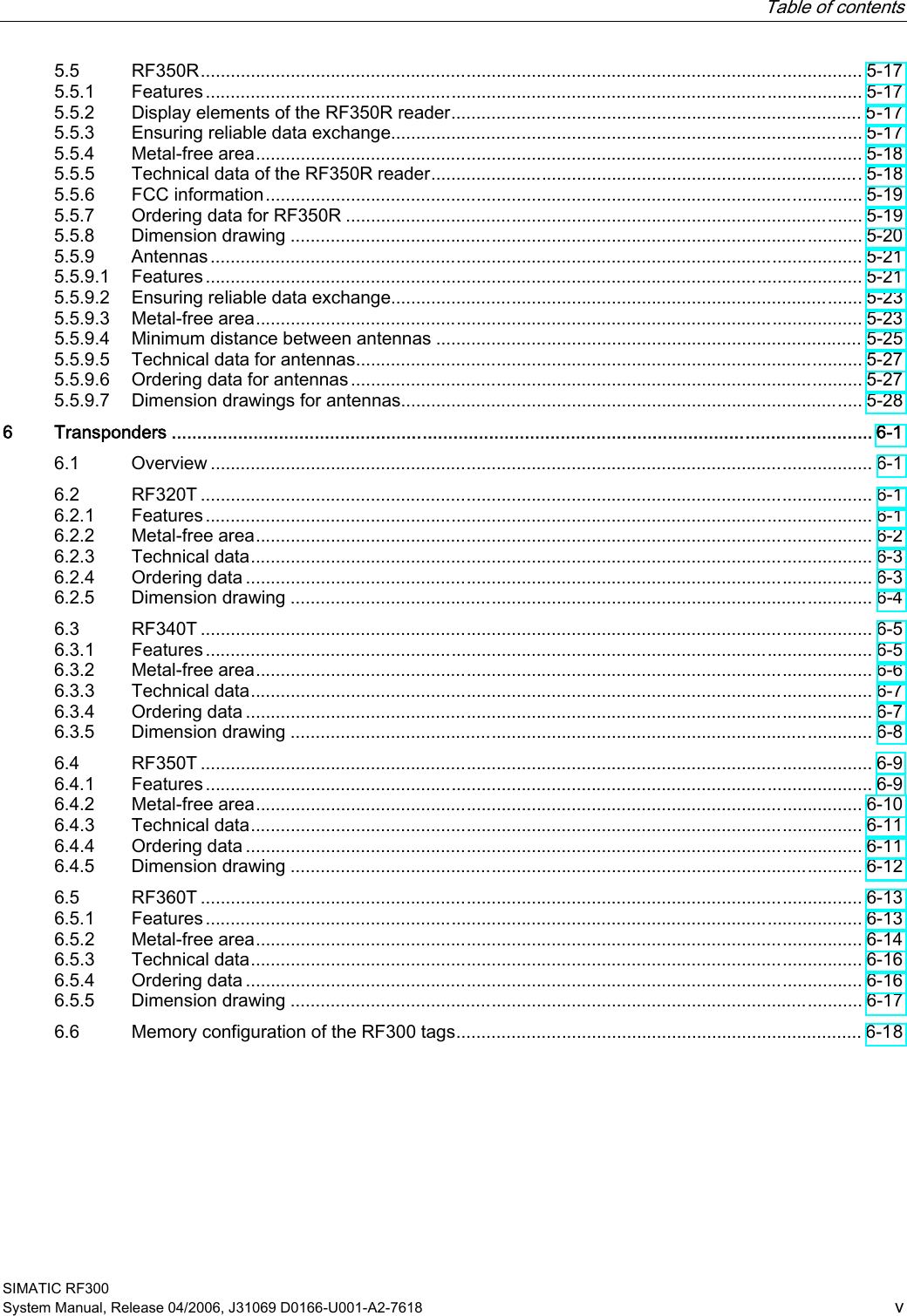
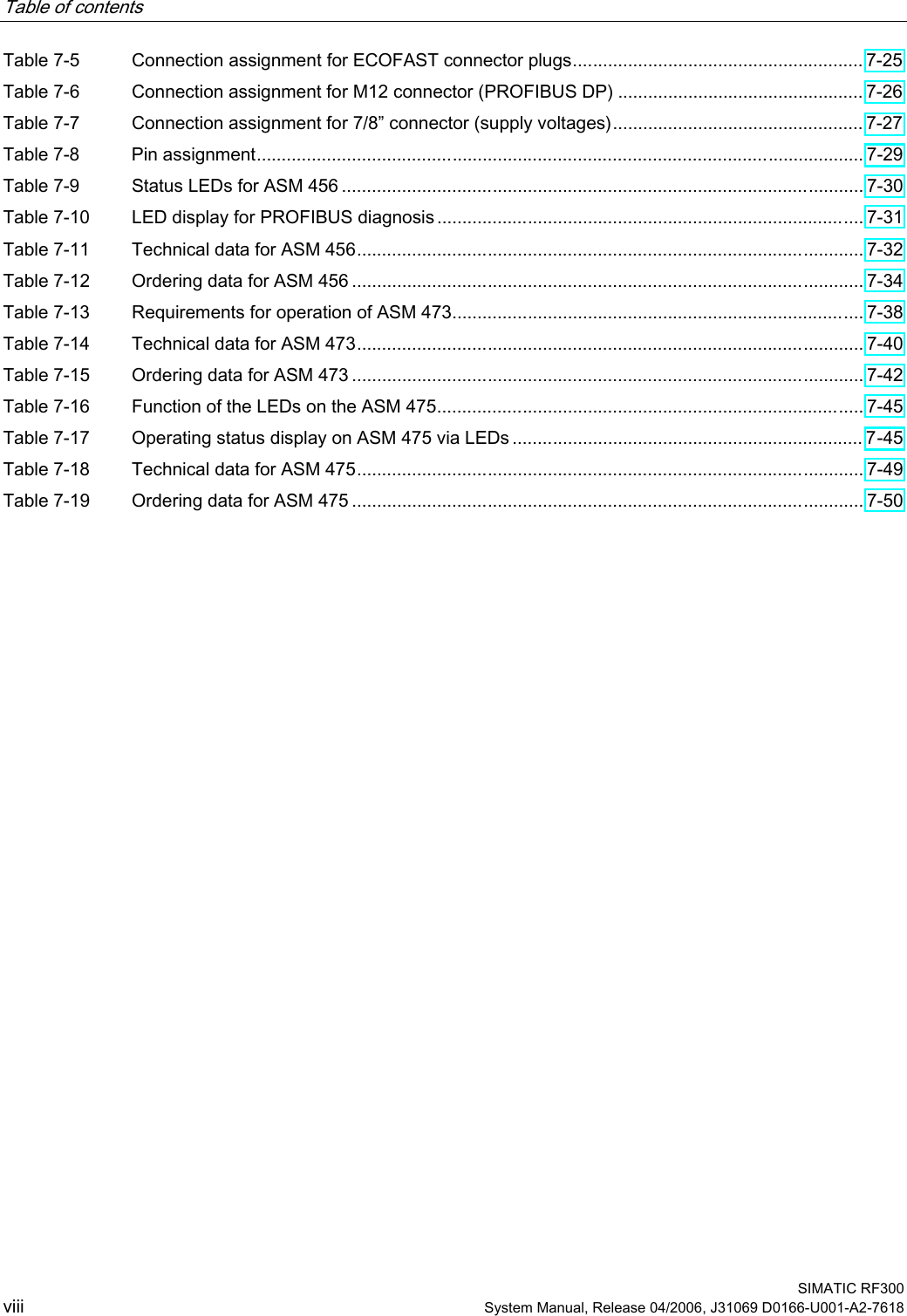
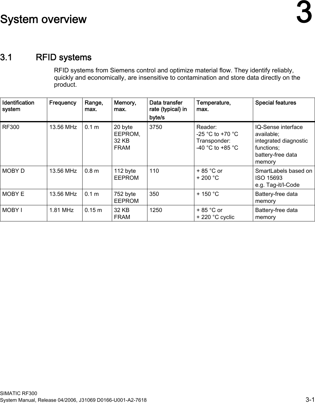
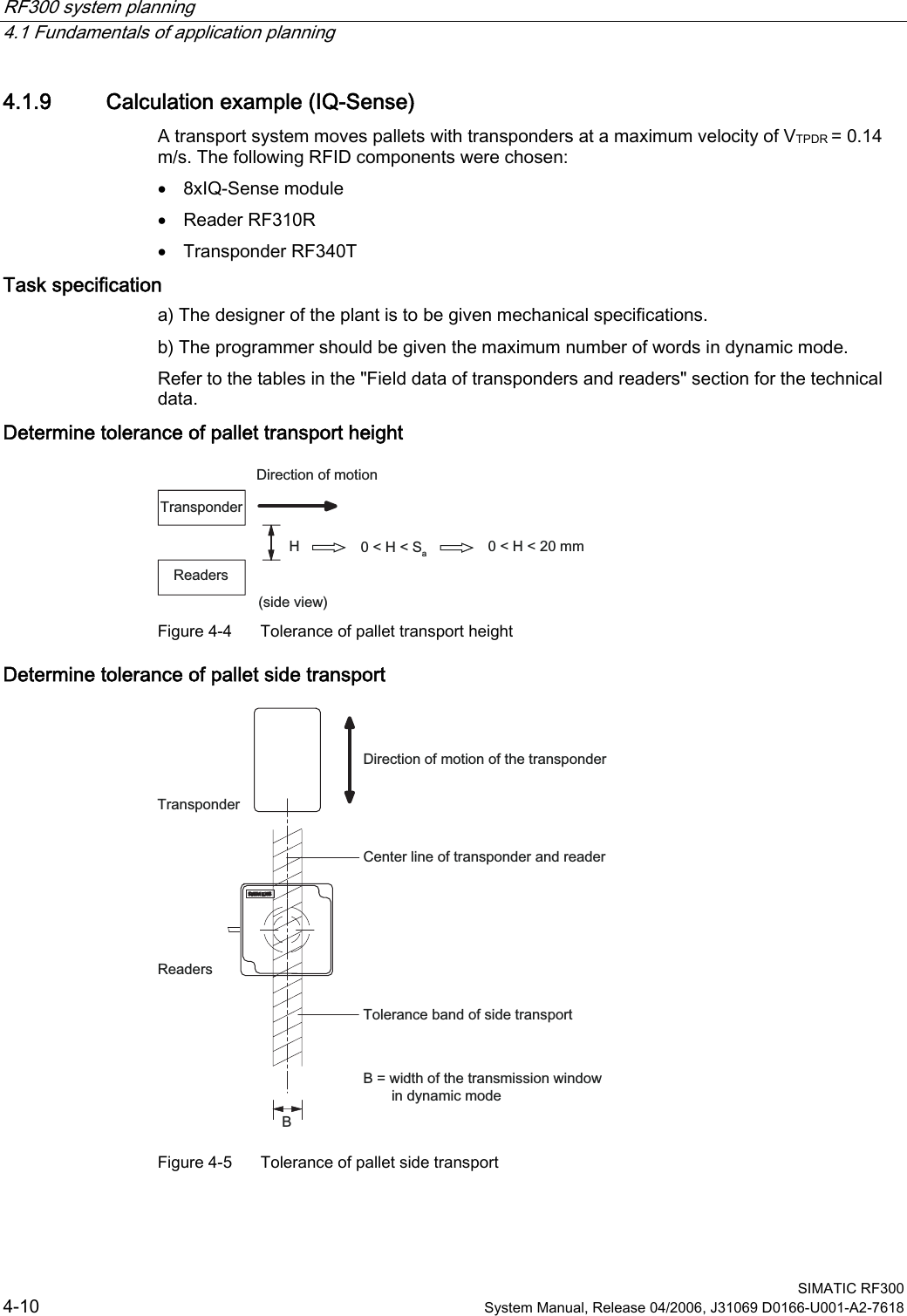
![RF300 system planning 4.1 Fundamentals of application planning SIMATIC RF300 4-8 System Manual, Release 04/2006, J31069 D0166-U001-A2-7618 4.1.7 Dwell time of the transponder The dwell time is the time in which the transponder remains within the transmission window of a reader. The reader can exchange data with the transponder during this time. The dwell time is calculated thus: 0,8[ ][/]TPDRvLmtvms⋅= tV: Dwell time of the transponder L: Length of the transmission window vTPDR: Speed of the transponder (TPDR) in dynamic mode 0,8: Constant factor used to compensate for temperature impacts and production tolerances The dwell time can be of any duration in static mode. The dwell time must be sufficiently long to allow communication with the transponder. The dwell time is defined by the system environment in dynamic mode. The volume of data to be transferred must be matched to the dwell time or vice versa. In general: Kvtt≥ tV:: Dwell time of the data memory within the field of the reader tK: Communication time between transponder and communication module](https://usermanual.wiki/Siemens/RF350R.Manual-Part-1/User-Guide-674261-Page-28.png)
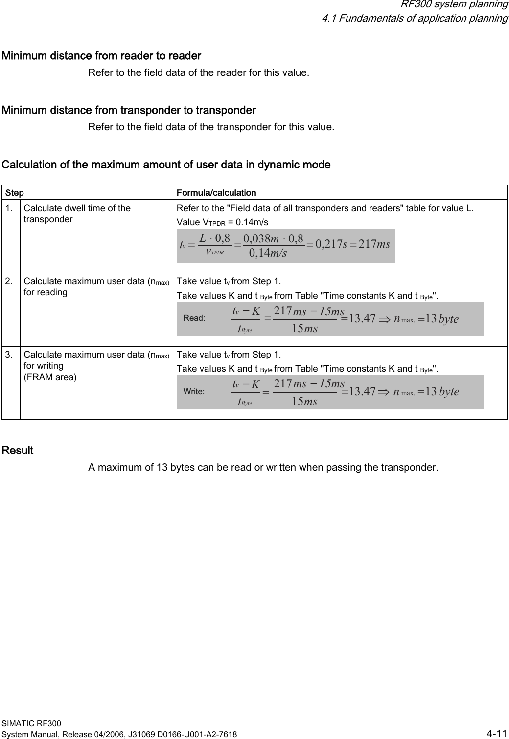
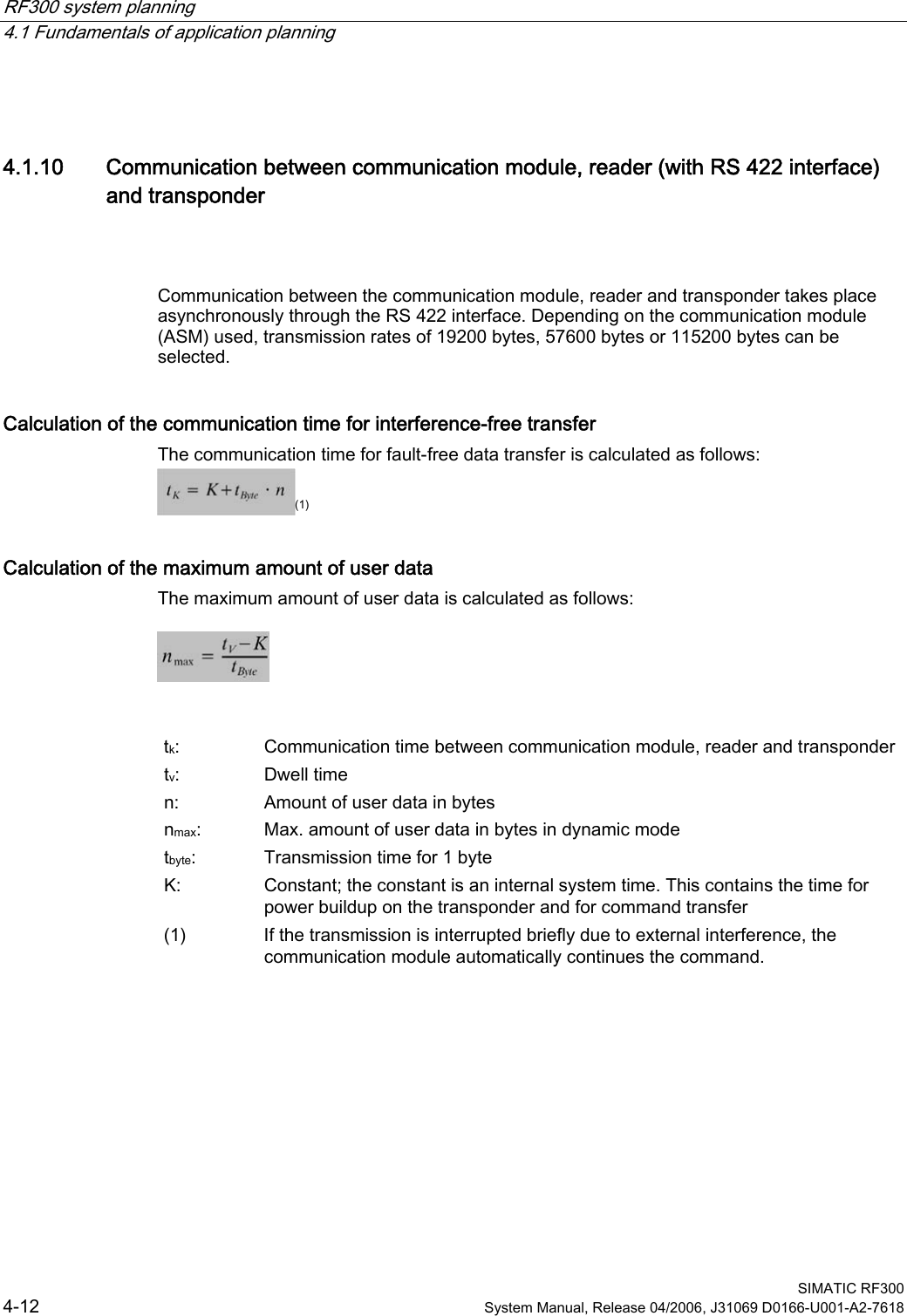
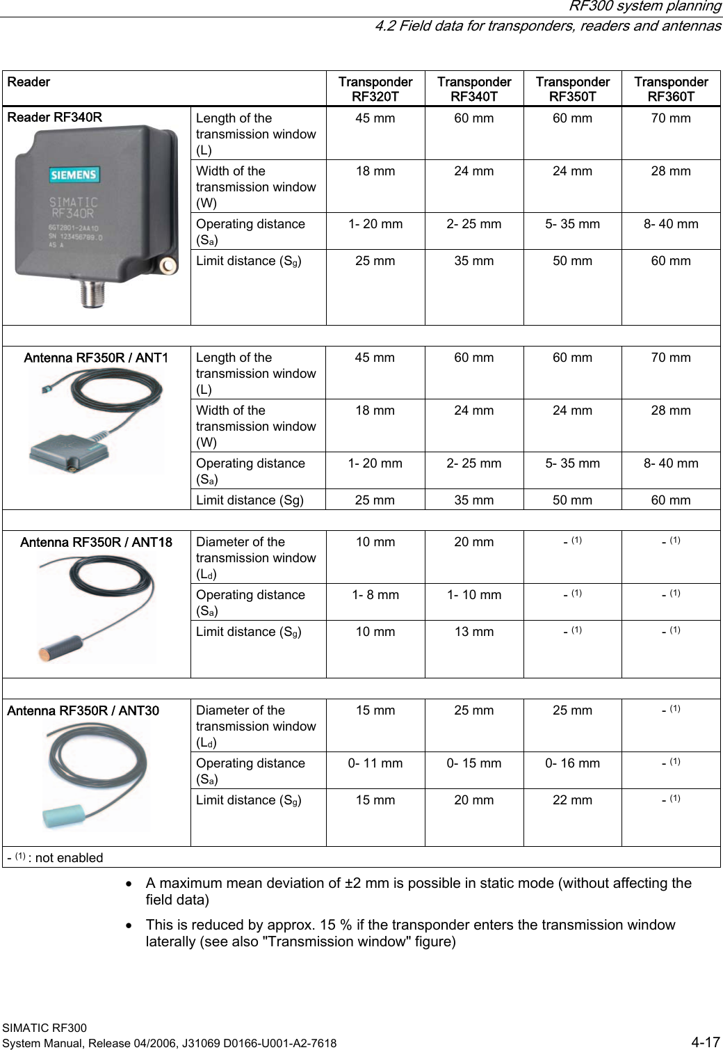
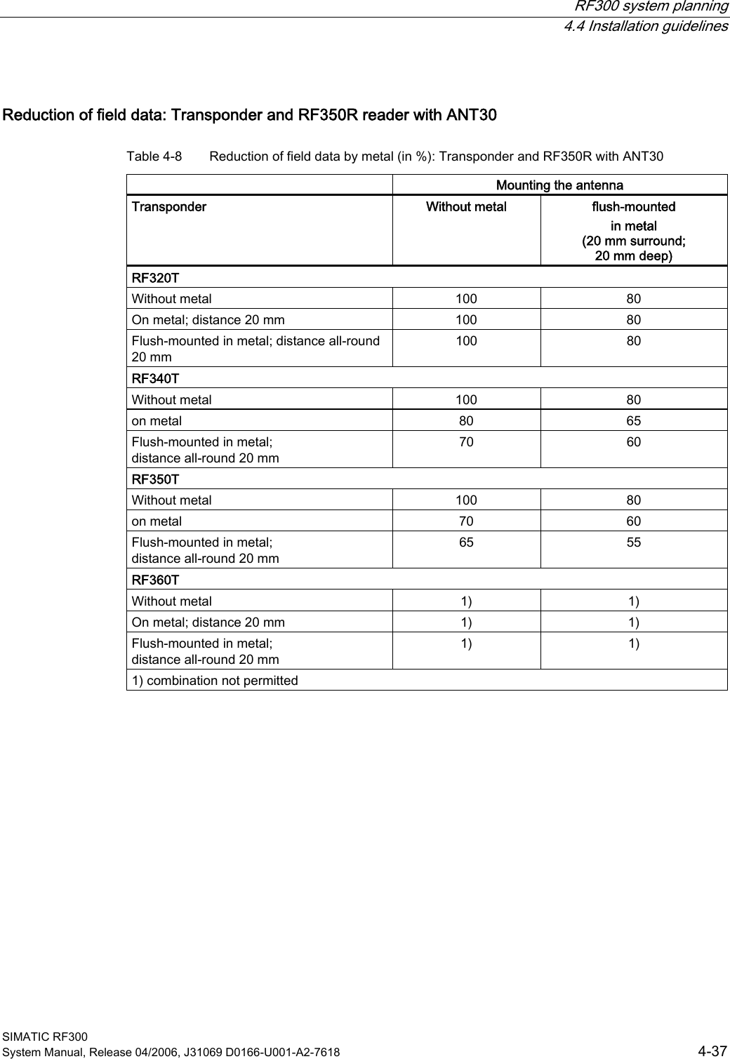
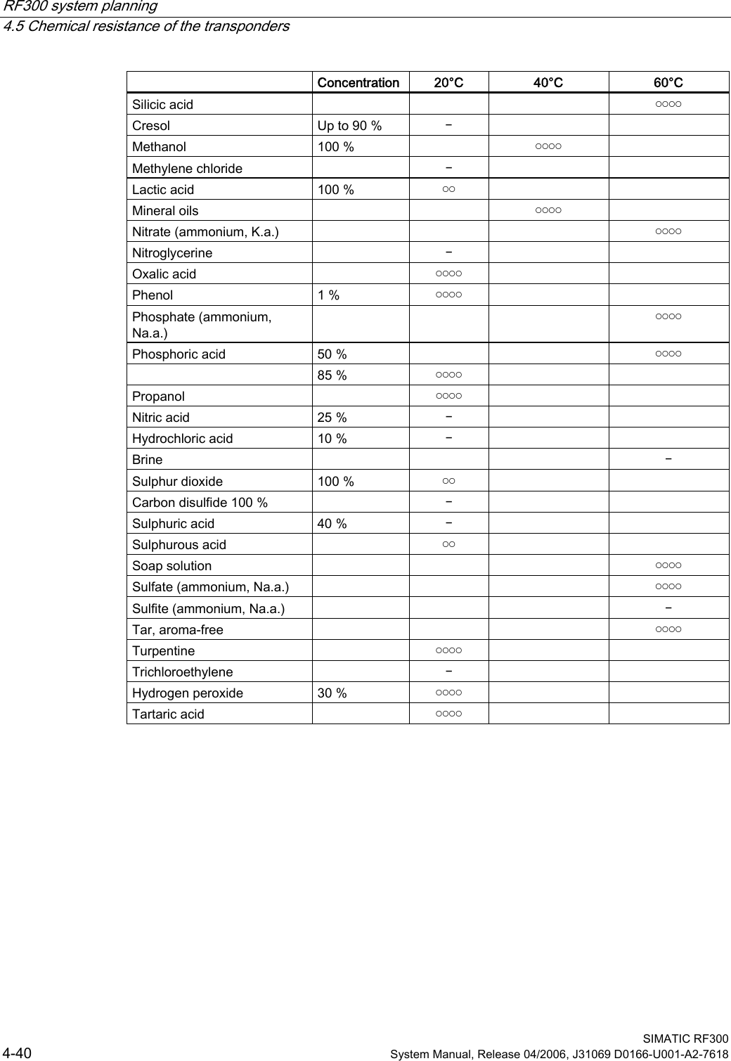
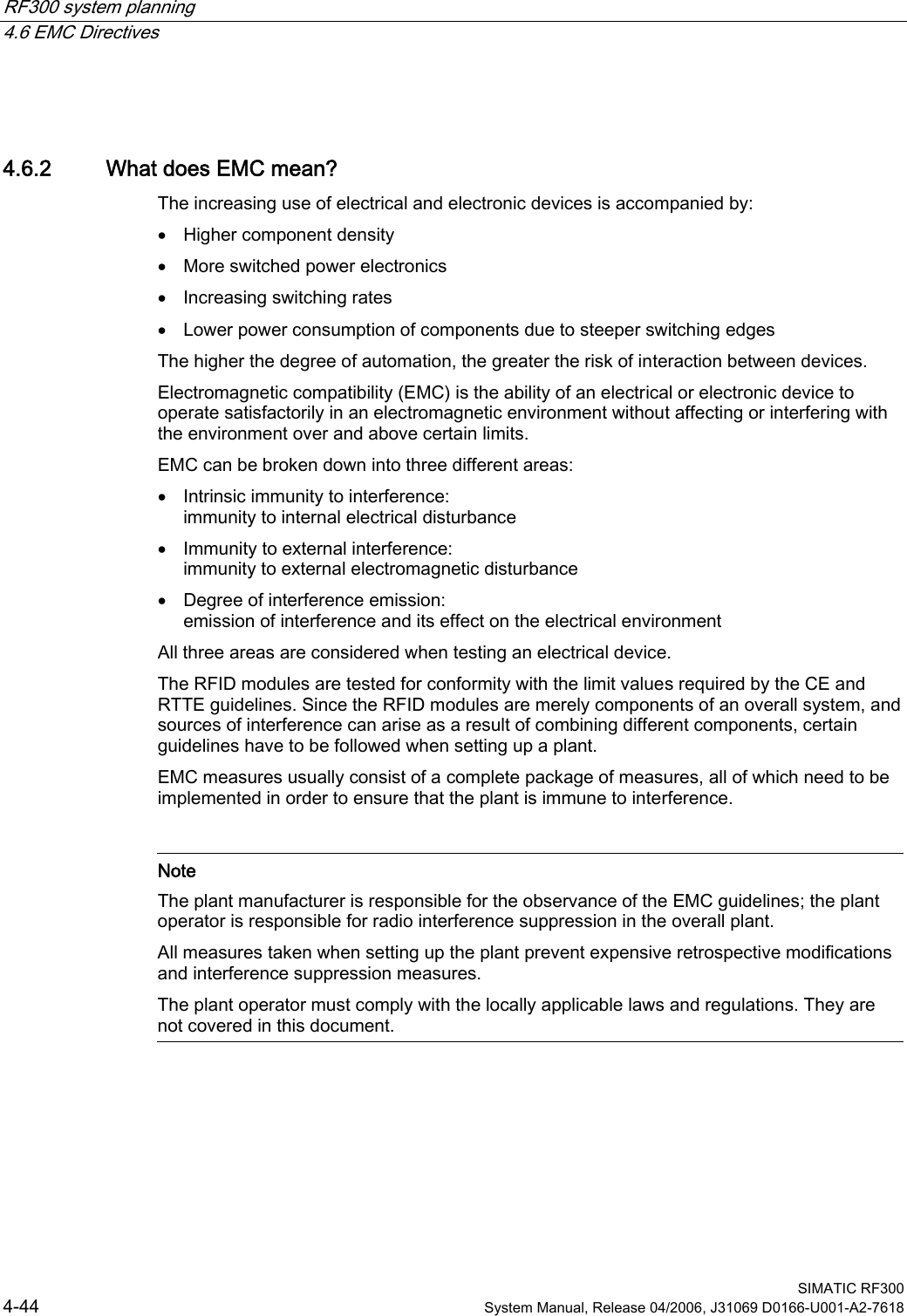
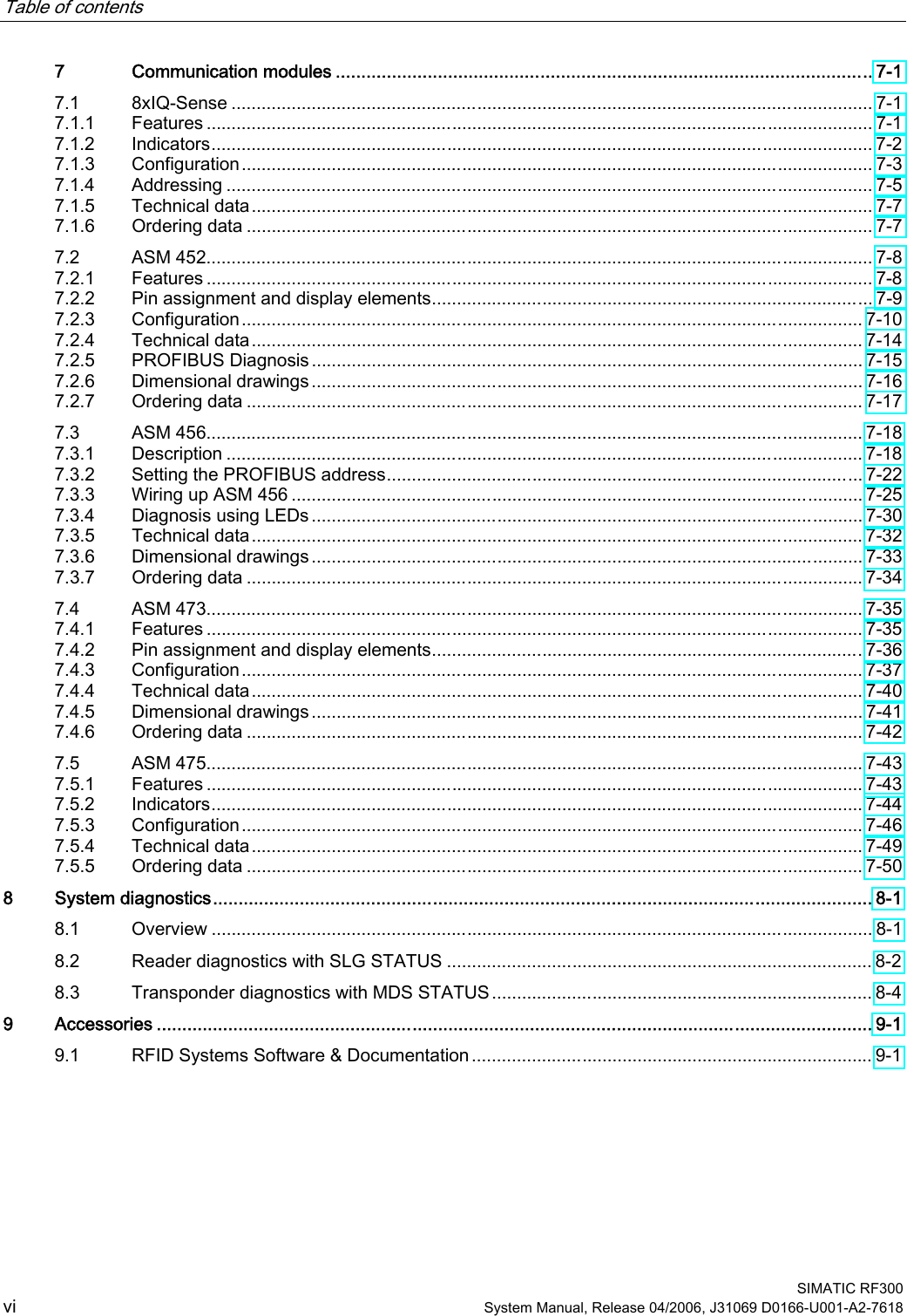
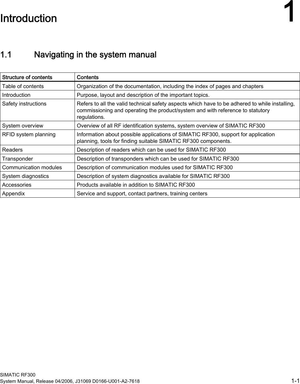
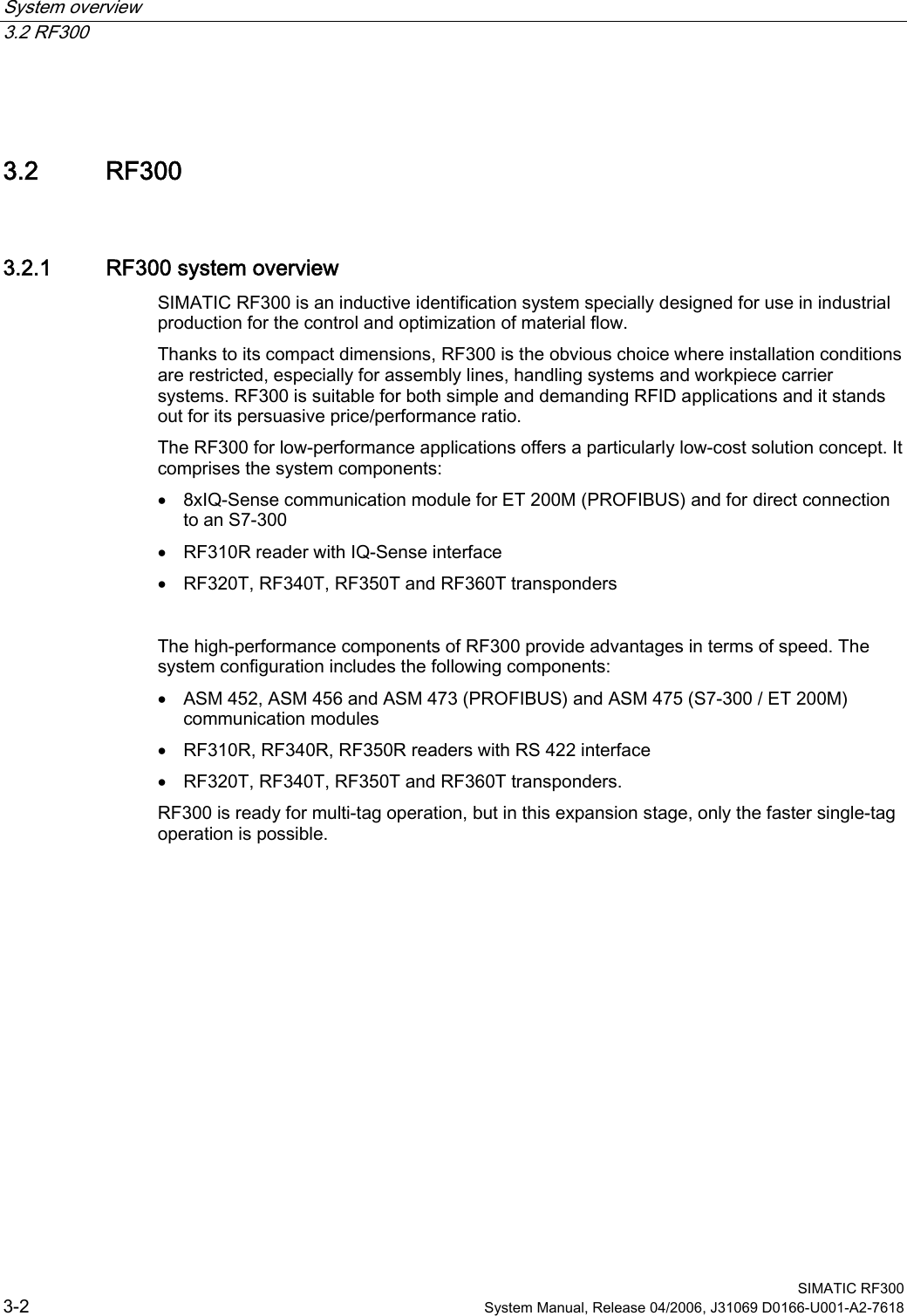
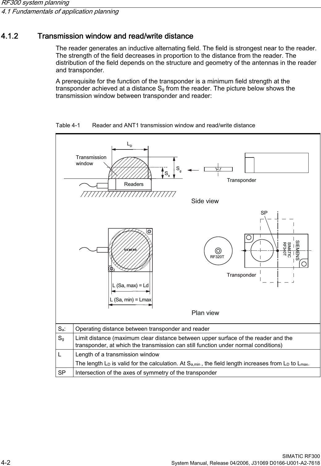
![RF300 system planning 4.1 Fundamentals of application planning SIMATIC RF300 System Manual, Release 04/2006, J31069 D0166-U001-A2-7618 4-13 Time constants K and tbyte Transmission rate [baud] K [ms] tbyte [ms] 19200 28 0,85 57600 14 0,38 115200 11 0,28 The values for K and tbyte include the overall time that is required for communication in static mode. It is built up from several different times: • Serial communication between communication module, reader and • Processing time between reader and transponder and their internal processing time. The values shown in the table must be used when calculating the maximum quantity of user data in static mode. They are applicable for both reading and writing in the FRAM area. For writing in the EEPROM area (max. 20 bytes), the byte time tByte is approx. 11 ms. Transmission rate [baud] Memory area K [ms] tbyte [ms] Independent FRAM 8,5 0,13 Independent Write Read EEPROM 8,5 8,5 12,2 0,13 In dynamic mode, the values for K and tbyte are independent of the transmission speed. The communication time only includes the processing time between the reader and the transponder and the internal system processing time of these components. The communication times between the communication module and the reader do not have to be taken into account because the command for reading or writing is already active when the transponder enters the transmission field of the reader. The values shown above must be used when calculating the maximum quantity of user data in dynamic mode. They are applicable for both writing and reading.](https://usermanual.wiki/Siemens/RF350R.Manual-Part-1/User-Guide-674261-Page-33.png)