Contents
- 1. User Manual
- 2. User Manual II
User Manual II
Readers
5.2 RF630R reader
SIMATIC RF600
System Manual, 12/2009, J31069-D0171-U001-A9-7618 121
5.2 RF630R reader
5.2.1 Description
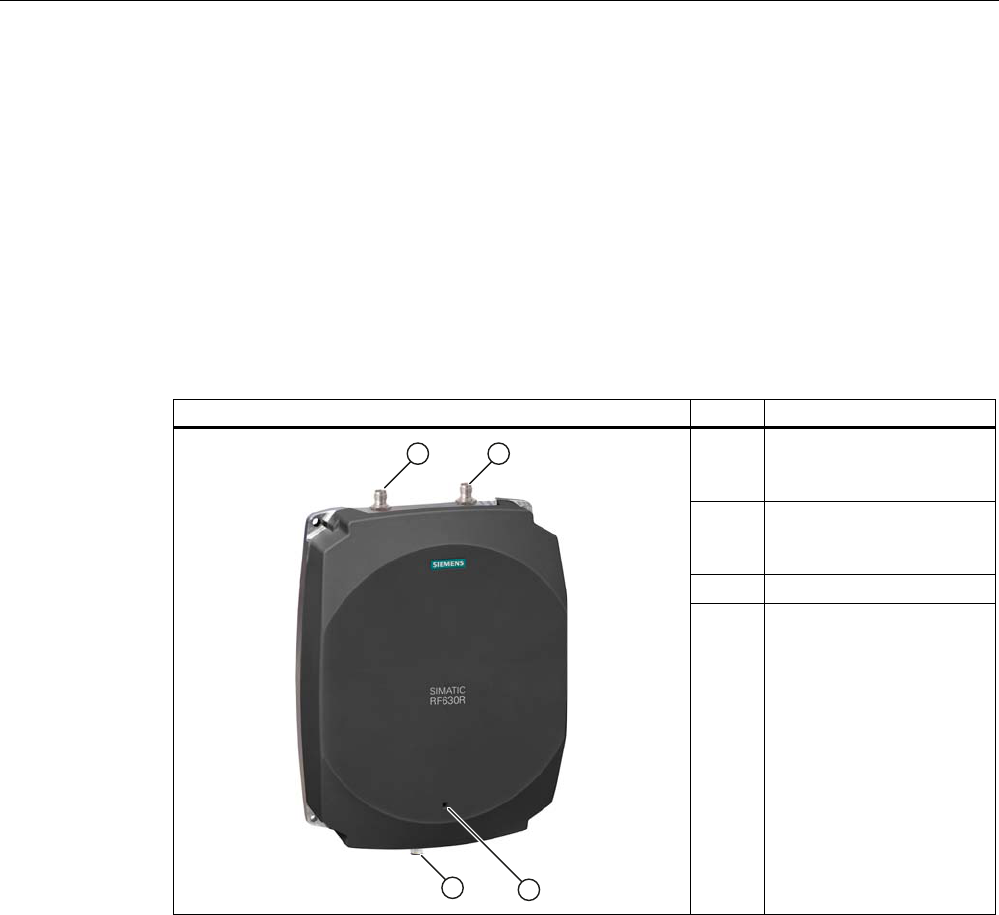
The SIMATIC RF630R is an active stationary reader in the UHF frequency range without an
integrated antenna. Up to two external UHF RFID antennas can be connected via TNC
reverse connections.
The maximum HF power output is 0.5 W on the reader output. The SIMATIC RF630R is
connected to a SIMATIC S7 controller via an ASM interface module. The degree of
protection is IP65.
Item Description
(1) TNCreverse interface for
connection of antenna 1
(ANT 1)
(2) TNCreverse interface for
connection of antenna 2
(ANT 2)
(2) LED status indicator
(3) RS 422 interface
(8-pin M12 connector)
Readers
5.2 RF630R reader
SIMATIC RF600
122 System Manual, 12/2009, J31069-D0171-U001-A9-7618
Highlights
● The tags are read in accordance with the requirements of the EPCglobal Class 1, Gen 2
and ISO/IEC 18000-6C standards
● Supports low-cost SmartLabels as well as reusable, rugged data media
● High reading speed: Depending on the function block (multitag mode), many tags can be
detected simultaneously (bulk reading), rapidly moving tags are reliably acquired.
● The RF630R (ETSI) "6GT2811-4AA00-0AA0" is suitable for the frequency band 865 to
868 MHz UHF (EU, EFTA, Turkey). The reader supports the ETSI EN 302 208 V1.1.1
standard as well as the new ETSI EN 302 208 V1.2.1 standard (4-channel plan).
● The RF630R (FCC) "6GT2811-4AA00-1AA0" is suitable for the frequency bands 920.25
to 924.75 MHz (Thailand) and 902 to 928 MHz (North America).
● Up to 2 external antennas can be connected and configured in operating mode
● IP65 degree of protection for reader
● Can be used for a high temperature range
● Dense Reader Mode (DRM) for environments in which many readers are operated in
close proximity to each other
● TIA system interface:
– RS 422
5.2.1.1 Ordering data
Device Order No.
RF630R (ETSI) reader basic unit for EU, EFTA, Turkey 6GT2811-4AA00-0AA0
RF620A antennas for EU, EFTA, Turkey (868 MHz)
RF660A antennas for EU, EFTA, Turkey (868 MHz)
6GT2812-1EA00
6GT2812-0AA00
RF630R (FCC) reader basic unit for the USA 6GT2811-4AA00-1AA0
RF620A Antennas for the USA and China (915 MHz)
RF660A Antennas for the USA and China (915 MHz)
6GT2812-1EA01
6GT2812-0AA01
Accessories Designation Order No.
Antenna cable 3 m (cable attenuation: 1.0 dB)
10 m (cable attenuation: 2.0 dB)
10 m (cable attenuation: 4.0 dB)
20 m (cable attenuation: 4.0 dB)
6GT2815-0BH30
6GT2815-1BN10
6GT2815-0BN10
6GT2815-0BN20
Connecting cable RS 422, M12 plug, 8-pin socket: 2 m
RS 422, M12 plug, 8-pin socket: 5 m
RS 422, M12 plug, 8-pin socket: 10 m
RS 422, M12 plug, 8-pin socket: 20 m
RS 422, M12 plug, 8-pin socket: 50 m
6GT2891-0FH20
6GT2891-0FH50
6GT2891-0FN10
6GT2891-0FN20
6GT2891-0FN50
Software & Documentation RFID CD-ROM 6GT2080-2AA10
Readers
5.2 RF630R reader
SIMATIC RF600
System Manual, 12/2009, J31069-D0171-U001-A9-7618 123
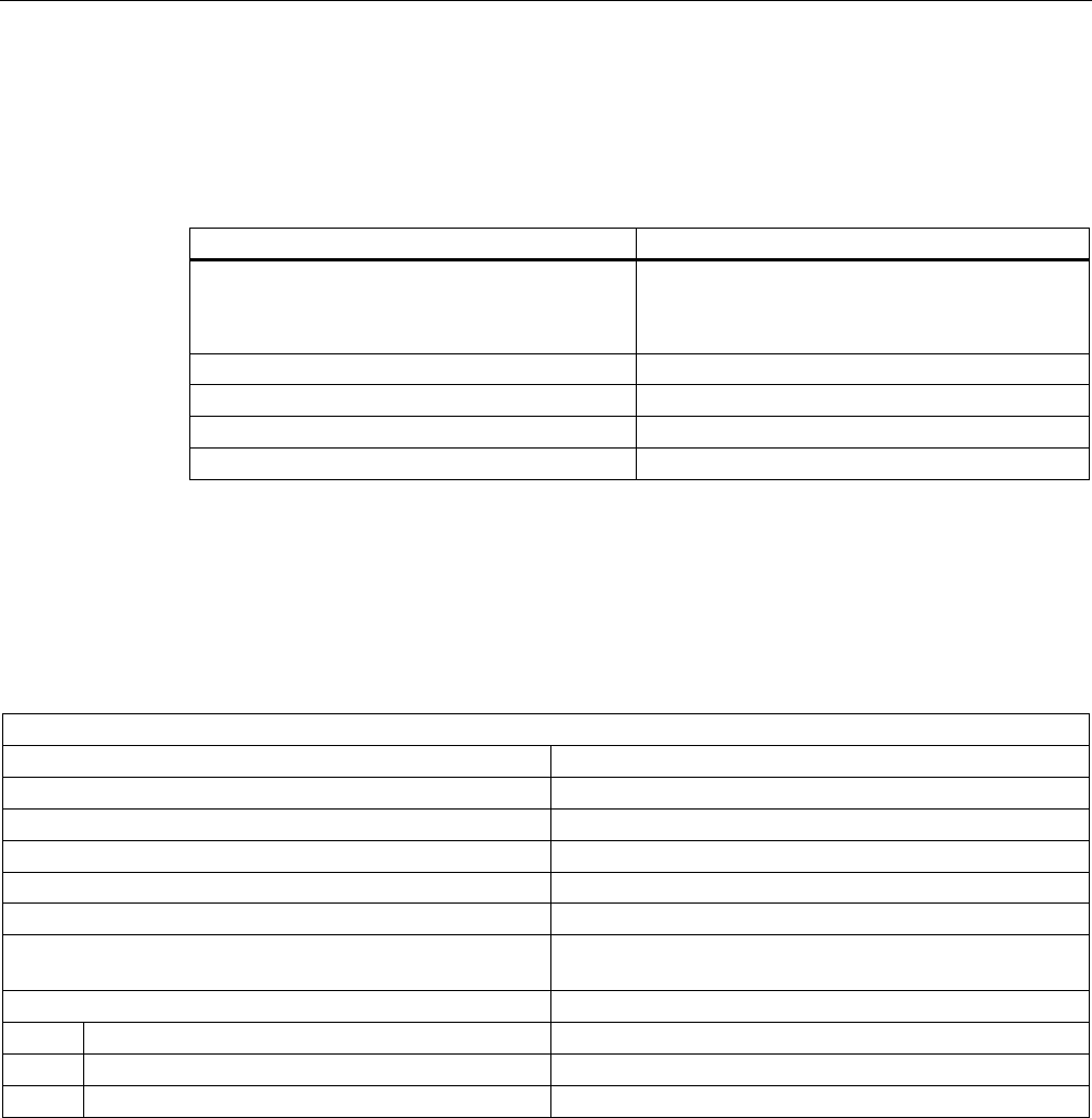
5.2.1.2 Status display
The device is equipped with a three colored LED. The LED can be lit in green, red or yellow.
The meaning of the indication changes in accordance with the color and state (on, off,
flashing) of the LED:
Green
LED
Red LED Yellow
LED
Meaning
Off Off Off The device is starting up.
Flashing Off Off The device is ready. The antenna is switched off.
On Off Off The device is ready. The antenna is switched on.
Off Off On "With presence": At least one tag is in the field.
"Without presence": Communication with a tag is active.
Off Flashing Off Reader is not active, a serious error has occurred. In addition, this LED also indicates
the fault status through the number of flashing pulses. Reboot (operating voltage Off
→ On is necessary).
The LED flashes once for the 'INACTIVE' status, rebooting is not necessary in this
case.
For more detailed information on the flash codes of the reader see Chapter Error messages
and flash codes for RF620R/RF630R (Page 330)
Note
LED not lit yellow?
If the LED does not light up yellow even though a tag is located within the field, common
causes are:
• Incorrect configuration in the init_run command, or init_run command was not executed
(see "Configuration Manual RF620R/RF630R")
• Antenna is switched off
• A tag is used, that is not compatible with the reader protocol (EPC Global Class 1 Gen 2).
• Tag is defective
• Reader or antenna has a defect
• Tag is not in the field of radiation of the transmit antenna
Readers
5.2 RF630R reader
SIMATIC RF600
124 System Manual, 12/2009, J31069-D0171-U001-A9-7618
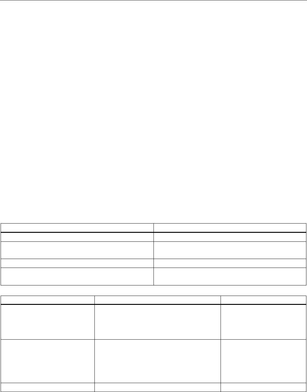
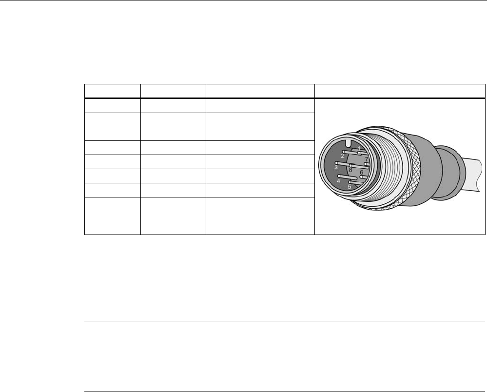
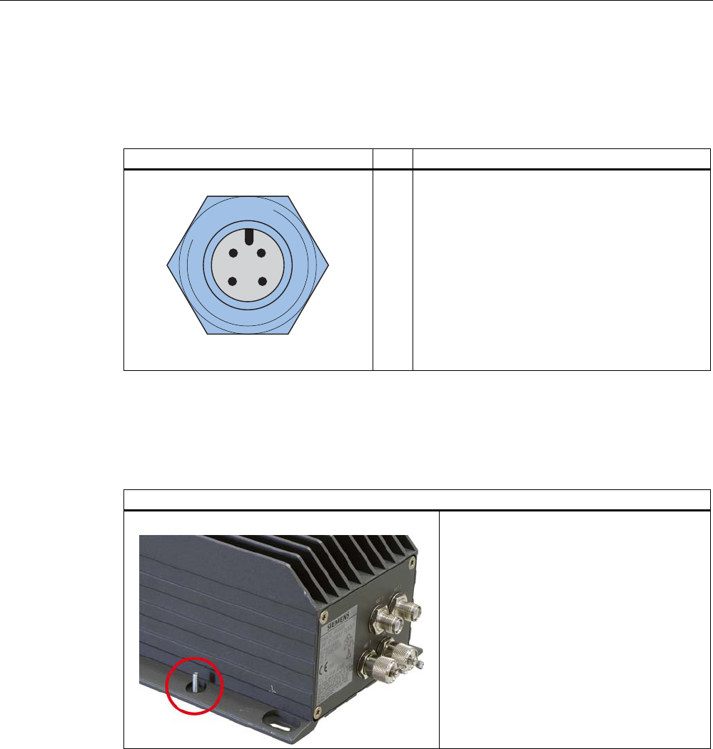
5.2.1.3 Pin assignment of the RS422 interface
Pin Pin
Device end
8-pin M12
Assignment
1 + 24 V
2 - Transmit
3 0 V
4 + Transmit
5 + Receive
6 - Receive
7 Free
8 Earth (shield)
The knurled bolt of the M12 plug is not connected to the shield (on the reader side).
Note
You must therefore not use any SIMATIC connecting cables that use the angled M12 plug.
Readers
5.2 RF630R reader
SIMATIC RF600
System Manual, 12/2009, J31069-D0171-U001-A9-7618 125
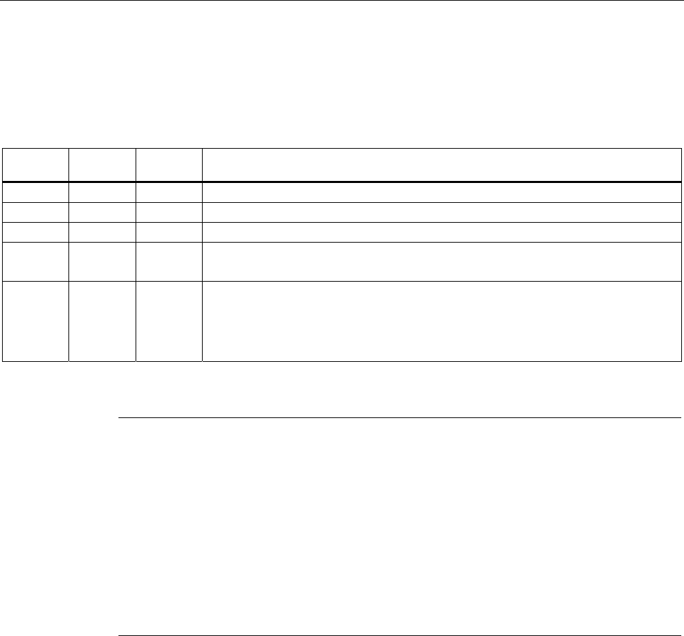
5.2.1.4 Pin assignment of the connecting cable
Table 5- 6 RS 422 - on reader side
M12 pin Core color Pin assignment View of M12 connector
1 white 24 VDC
2 brown TX neg
3 green GND
4 yellow TX pos
5 Gray RX pos
6 pink RX neg
7 blue Not assigned
8 red Earth (shield)
Comment
This cable has an 8-pin M12 connector at one end and the other cable end is 'open'. There
are 8 color-coded single cores there for connecting to external devices. There are different
cable lengths in the product range (3 m to 50 m). Long cables can be reduced if necessary.
Note
For long cables: Adapt supply voltage and data rate accordingly
Note that with long cables in particular, the supply voltage of 24 V DC must always be
applied. Note also that the data rate on the serial interface must, if necessary, be reduced.
(See "Configuration Manual RF620R/RF630R")
Readers
5.2 RF630R reader
SIMATIC RF600
126 System Manual, 12/2009, J31069-D0171-U001-A9-7618
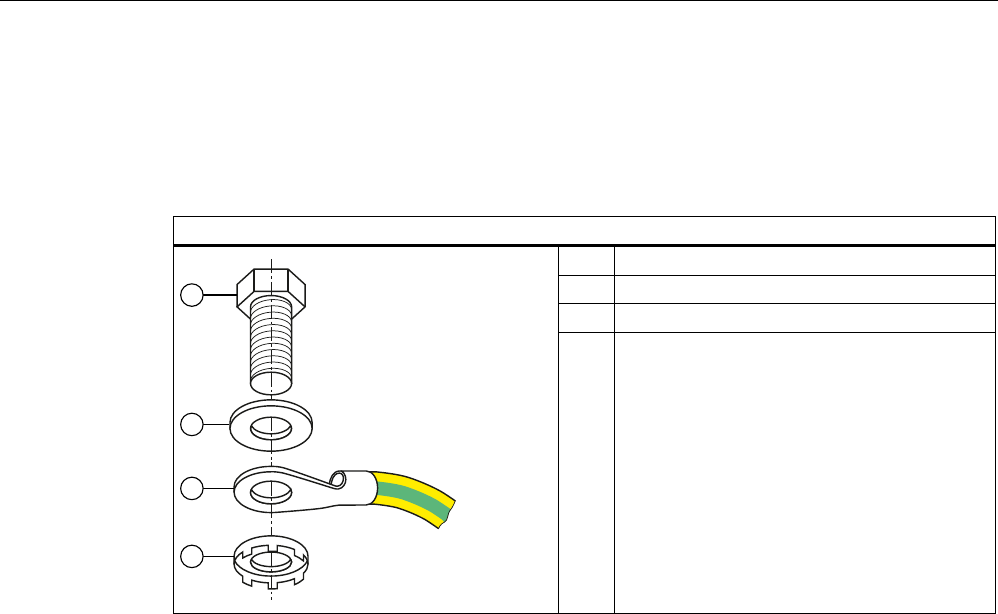
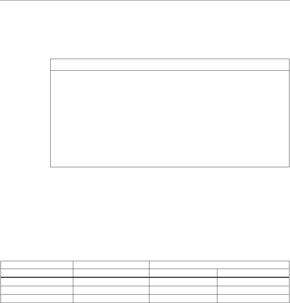
5.2.1.5 Grounding connection
The RF620R/RF630R can be electrically connected to the ground potential through a contact
washer. The tightening torque must be increased in this case to ensure that electrical contact
is made (2.7 Nm).
Ground connection
(a) Hexagon-head screw
(b) Plain washer
(c) Cable lugs
D
E
G
F
(d) Contact washer:
Use contact washers according to the
Siemens standard SN 70093-6-FSt-flNnnc-
480h for ground connection,
Siemens item No.: H70093-A60-Z3
5.2.2 Planning application
5.2.2.1 Minimum mounting clearances of two antennas of different readers
At 500 mW ERP radiated power, due to the opening angle of the antennas, their fields can
overlap considerably. It is no longer possible to clarify in which antenna field access to the
data of a tag is performed.
In order to avoid this, always keep a minimum distance of 3 m between two antennas of
different RF630R readers with the maximum radiated power of 500 mW ERP.
Dense Reader Mode (DRM)
The readers can also interfere with each other (secondary fields), if the channels (Reader
TX, Transponder TX) overlap. In order to prevent a transponder channel overlapping with a
reader channel, we recommend that the Dense Reader Mode (DRM) is used.

Readers
5.2 RF630R reader
SIMATIC RF600
System Manual, 12/2009, J31069-D0171-U001-A9-7618 127
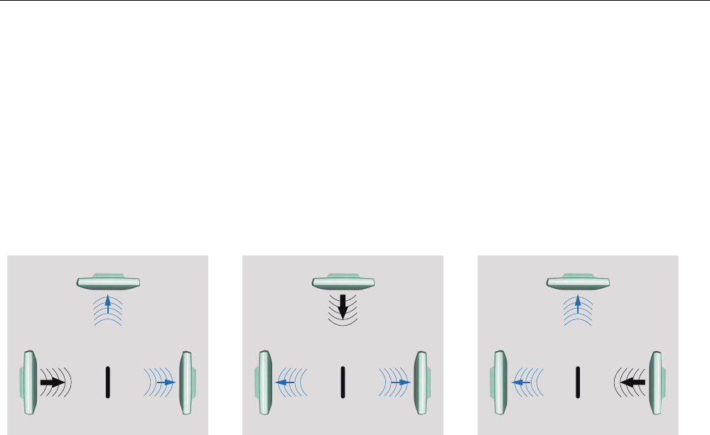
5.2.2.2 Antenna/read point configurations
You can connect up to two external antennas to the RF630R reader. The standard setting is
that two antennas are connected when the reader is started.
You have 3 possibilities for aligning the antennas and covering the read point.
One RF630R reader with two antennas and two read points
If you connect two external antennas to the device and align them in different directions, you
can read tags at two different read points. With this technique, a particular antenna must be
switched off application-dependently to be able to establish which tags have been read from
which antenna. The reader also provides a mode for this purpose in which the antennas can
be switched on and off cyclically (both antennas must be connected). Note the minimum
distances between the antennas for the antenna configuration (see Chapter Specified
minimum and maximum spacing of antennas (Page 49) .
One RF630R reader with two antennas and one read point
If you connect two external antennas to the device and align them in the same direction
(portal configuration), you can read tags at one read point. With this method, the reader
automatically switches between the two antennas while the tags are being read. Note the
minimum distances between the antennas for the antenna configuration (see Chapter
Specified minimum and maximum spacing of antennas (Page 49) .
One RF630R reader with one antenna and one read point
If you connect an external antenna to the device, you can read tags at one read point.
Readers
5.2 RF630R reader
SIMATIC RF600
128 System Manual, 12/2009, J31069-D0171-U001-A9-7618
5.2.3 Installing/Mounting
5.2.3.1 Mounting/Installation
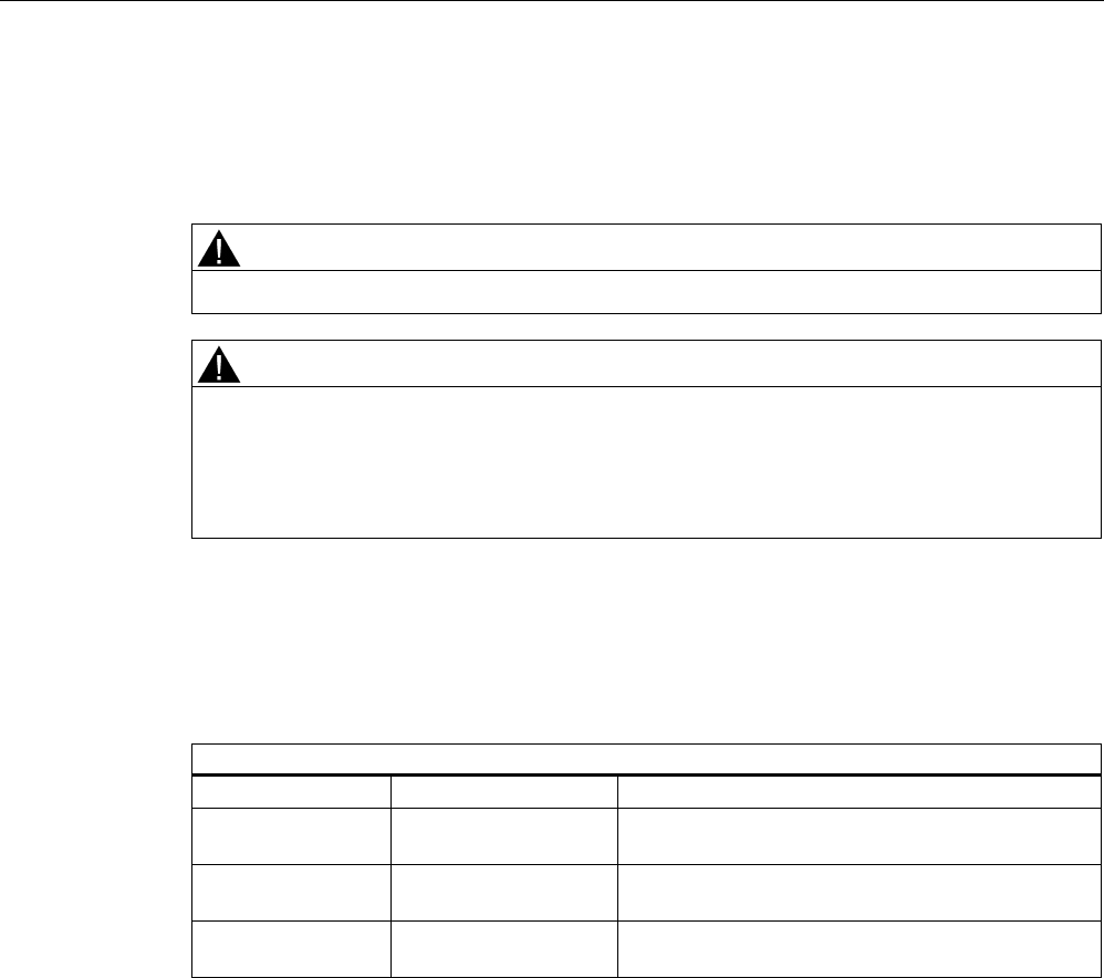
Requirement
WARNING
Ensure that the wall or ceiling can hold four times the total weight of the device.
CAUTION
Emitted radiation
The transmitter complies with the requirements of Health Canada and the FCC limit values
for subjecting persons to HF radiation, provided that a minimum spacing of 26 cm exists
between antenna and person. When the antennas are installed, you must therefore ensure
that a minimum spacing of 26 cm is maintained between personnel and antennas.
Mounting/installing the device
You can mount the reader directly onto a flat surface.
The positions of the fixing holes for the device are shown in the section Dimension drawings
(Page 134).
Readers
5.2 RF630R reader
SIMATIC RF600
System Manual, 12/2009, J31069-D0171-U001-A9-7618 129
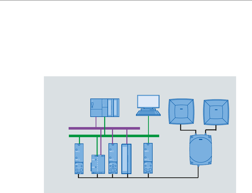
5.2.4 Configuration/integration
The RS422 system interface is provided for integrating the device into system
environments/networks. The system interface transfers data to SIMATIC controllers or PCs
with the appropriate interface.
Apart from transmitting communication data from the reader to the controller and vice versa,
the RS422 interface also supplies power to the reader (24 V DC).
3URILQHW
3URILEXV
6,0$7,&6
5)&
56'&9
5)& $60
5)5
6,0$7,&5)$ 6,0$7,&5)$
$60 5)&
Figure 5-7 Overview of configuration of the RF630R reader
The RF630R reader can alternatively be connected to a SIMATIC controller via the ASM
456, ASM 475, RF170C and RF180C interface modules/communication modules.
The RF630R reader can alternatively also be connected directly to the PC via the RF182
communication module.
For further details on the interface modules used, see Chapter RF660R (Page 309) .
Further information about commissioning the readers can be found in the Configuration
Manual "RF620R/RF630R" in the "Commissioning" section.
Readers
5.2 RF630R reader
SIMATIC RF600
130 System Manual, 12/2009, J31069-D0171-U001-A9-7618
5.2.4.1 Transmission protocols
RS 422 communication
3964R protocol
Transmission rates 19.2 kbps
57.6 kbps
115.2 kbps
Start bits 1
Data bits 8
Parity Odd
Stop bits 1
5.2.5 Technical data
5.2.5.1 Mechanical data
Mechanical data
Weight 1640 g
Dimensions (L x W x H) in mm 252 x 193 x 52 mm, without connections
Material for housing top section ABS (GF 20)
Material for housing bottom section Aluminum
Color of housing top section Anthracite
Color of housing bottom section Silver
Status displays on the device 1 LED
Colors: Red, yellow, green
Interfaces
Antenna connections 2x RTNC plug
RS422 1 x plug (8-pin M12)
Software SIMATIC S7

Readers
5.2 RF630R reader
SIMATIC RF600
System Manual, 12/2009, J31069-D0171-U001-A9-7618 131
Thermal and electrical properties
MTBF (Mean Time Between Failures) 16 years
Supply voltage
• Permitted range
21.6 to 30 V DC 1
Supply voltage Current consumption
(in standby mode, no
transmit power)
Current consumption
(in standby mode, no
transmit power)
20 V input voltage on the reader, typical 135 mA 2.7 W
24 V input voltage on the reader, typical 115 mA 2.76 W
30 V input voltage on the reader, typical 95 mA 2.85 W
Supply voltage Current consumption
(at 500 mW ERP)
Power requirement
(at 500 mW ERP)
20 V input voltage on the reader, typical 470 mA 9.4 W
24 V input voltage on the reader, typical 395 mA 9.48 W
30 V input voltage on the reader, typical 320 mA 9.6 W
Rampup time 7 s
1) All supply and signal voltages must be safety extra low voltage (SELV/PELV according to EN 60950)
24 V DC power supply: safe (electrical) isolation of extra-low voltage (SELV / PELV acc. to EN 60950)
Mechanical environmental conditions
Shock resistant to EN 60068-2-27
Vibration EN 60068-2-6
50 g1
20 g1
Climatic Conditions
Ambient temperature during operation -25 °C to +55 °C
(a 10-minute warm-up time must be observed at an
operating temperature below -20 °C)
Ambient temperature for transport and storage -40 °C to +85 °C
1) The values for shock and vibration are maximum values and must not be applied continuously.

Readers
5.2 RF630R reader
SIMATIC RF600
132 System Manual, 12/2009, J31069-D0171-U001-A9-7618
EMC & approvals for ETSI variant
ETSI EN 301 489-1 / -3 Electromagnetic compatibility
ETSI EN 302 208
Approvals • Radio to R&TTE- guidelines EN 300 330, EN 301 489
• CE
• ETSI EN 302-208 V1.1.1
• ETSI EN 302-208 V1.2.1
• Reader degree of protection acc. to EN 60529 (IP65)
EMC & approvals for FCC variant
Electromagnetic compatibility FCC Part 15
Approvals • FCC, cULus
• IEC60950, including US and Canadian variants of it
• FCC CFR47 Part 15.247
• RoHS-compliant according to EU Directive 2002/95/EC
• Industrial Canada, RSS-210, Issue 7, June 2007
5.2.5.2 Technical data according to EPC and ISO
Technical data
Frequency accuracy max.± 10 ppm
Channel spacing EU, EFTA, Turkey: 200 kHz
US: 500 kHz
China: 250 kHz
Modulation methods ASK: DSB modulation & PR-ASK modulation
Encoding, Manchester or Pulse Interval (PIE)
Effective radiant power
(the radiant power depends on the antennas and cables
used, see Guidelines for selecting RFID UHF antennas
(Page 169) )
≤ 0.5 W ERP
ETSI frequencies
Frequency range EU, EFTA, Turkey
according to ETSI EN 302 208 V1.1.1 (commissioning until
December 31, 2009)
865 to 868 MHz (10 subchannels LBT at 2 W ERP, 12
subchannels at 0.5 W ERP, 15 subchannels LBT at 0.1 W
ERP)
Frequency bands for EU, EFTA, Turkey:
according to ETSI EN 302 208 V1.2.1 (valid since
November 4, 2008, publication in the Official Journal of the
European Union)
• 865.7 MHz
• 866.3 MHz
• 866.9 MHz
• 867.5 MHz
(4 channels LBT optional at max. 2 W ERP)
Readers
5.2 RF630R reader
SIMATIC RF600
System Manual, 12/2009, J31069-D0171-U001-A9-7618 133
Read distance for EU, EFTA, Turkey / China
Antennas mounted on opposing sides
(portal configuration)
max. 3.5 m (recommended maximum value for
configuration)
Antennas mounted on the same side Max. 2 m (recommended maximum value for configuration;
depending on the transponder)
FCC frequencies
North American frequency band 902 ... 928 MHz (50 channels, frequency hopping)
Frequency band for China 920.125 to 924.875 MHz (16 subchannels at 2 W ERP, 20
subchannels at 0.1 W ERP)
Read distance for USA
Antennas mounted on opposing sides
(portal configuration)
max. 3.5 m (recommended maximum value for
configuration)
Readers mounted on the same side max. 2 m (recommended maximum value for configuration)
5.2.5.3 Maximum number of readable tags
The maximum number of readable tags depends on the following parameters:
● Size of the antenna field
● Readability of the tags
For a transmit power of 500 mW ERP, the following is read when the tag RF620T is used:
● Max. 40 tags in the antenna field (tags perpendicular to antenna at 1 m distance). If 2
antennas are used, up to 80 tags can be recognized.
● Max. 18tags per second
Note for 2-antenna operation
● If 2 antennas are connected to the SIMATIC RF630R, the antennas must be controlled
using the SET-ANT command.
● If 2 antennas are configured as a gate, both antennas should be simultaneously switched
on with the SET-ANT command. The reader multiplexes both antennas internally. The
multiplexing time is 100 ms (internal changeover time from antenna to antenna).
Readers
5.2 RF630R reader
SIMATIC RF600
134 System Manual, 12/2009, J31069-D0171-U001-A9-7618
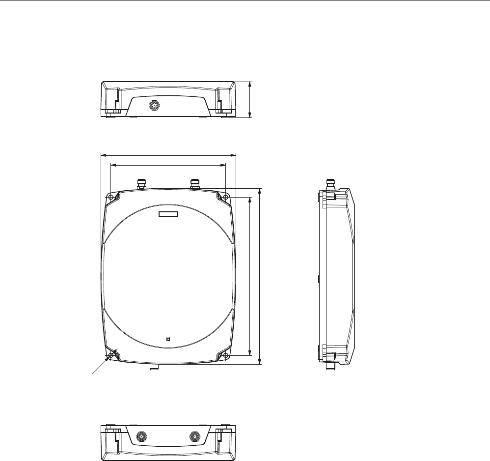
5.2.6 Dimension drawings
ෘ
Figure 5-8 Dimension drawing for RF630R
All dimensions in mm
Readers
5.2 RF630R reader
SIMATIC RF600
System Manual, 12/2009, J31069-D0171-U001-A9-7618 135
5.2.7 Certificates and approvals
Table 5- 7 6GT2811-4AA00-0AA0
Certificate Designation
CE approval according to R&TTE guideline
Table 5- 8 6GT2811-4AA00-1AA0
Standard
Federal Communications
Commission
FCC CFR 47, Part 15 sections 15.247
Radio Frequency Interference Statement
This equipment has been tested and found to comply with the limits
for a Class B digital device, pursuant to Part 15 of the FCC Rules.
FCC ID: NXW-RF630R
Industry Canada Radio
Standards Specifications
RSS-210 Issue 7, June 2007, Sections 2.2, A8
IC: 267X-RF630
This product is UL-certified for the USA and Canada.
It meets the following safety standard(s):
UL 60950-1 - Information Technology Equipment Safety - Part 1:
General Requirements
CSA C22.2 No. 60950 -1 - Safety of Information Technology
Equipment
UL Report E 205089

Readers
5.2 RF630R reader
SIMATIC RF600
136 System Manual, 12/2009, J31069-D0171-U001-A9-7618
5.2.7.1 FCC information
Siemens SIMATIC RF630R (FCC): 6GT2811-4AA00-1AA0
FCC ID: NXW-RF630R
This device complies with part 15 of the FCC rules.
Operation is subject to the following two conditions:
(1) This device may not cause harmful interference, and
(2) This device must accept any interference received, including interference that may cause
undesired operation.
Caution
Any changes or modifications not expressly approved by the party responsible for
compliance could void the user's authority to operate the equipment.
Note
This equipment has been tested and found to comply with the limits for a Class B digital
device, pursuant to part 15 of the FCC Rules. These limits are designed to provide
reasonable protection against harmful interference when the equipment is operated in a
commercial environment. This equipment generates, uses, and can radiate radio frequency
energy and, if not installed and used in accordance with the instruction manual, may cause
harmful interference to radio communications. Operation of this equipment in a residential
area is likely to cause harmful interference in which case the user will be required to correct
the interference at his own expense.
FCC NoticeTo comply with FCC part 15 rules in the United States, the system must be
professionally installed to ensure compliance with the Part 15 certification.
It is the responsibility of the operator and professional installer to ensure that only certified
systems are deployed in the United States. The use of the system in any other combination
(such as co-located antennas transmitting the same information) is expressly forbidden.
FCC Exposure InformationTo comply with FCC RF exposure compliance requirements, the
antennas used for this transmitter must be installed to provide a separation distance of at
least 20 cm from all persons and must not be co-located or operating in conjunction with any
other antenna or transmitter.
5.2.7.2 IC-FCB information
Siemens SIMATIC RF630R (FCC): 6GT2811-4AA00-1AA0
IC: 267X-RF630
Industry Canada NoticeTo reduce potential radio interference to other users, the antenna
type and its gain should be so chosen that the equivalent isotropically radiated power
(e.i.r.p.) is not more than that permitted for successful communication.
This device has been designed to operate with the SIMATIC RF620A antenna 902-928 as
well as the SIMATIC RF660A antenna 902-928 listed below, and having a maximum gain of
5,5 dBi.
Other antennas or antennas having a gain greater than 5,5 dBi are strictly prohibited for use
with this device.
The required antenna impedance is 50 Ohms.
Readers
5.3 RF660R reader
SIMATIC RF600
System Manual, 12/2009, J31069-D0171-U001-A9-7618 137
5.3 RF660R reader
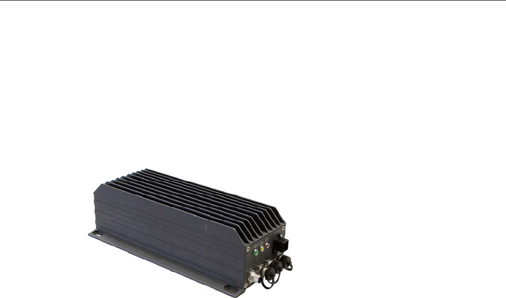
5.3.1 Description
SIMATIC RF660R is a stationary reader for connecting up to 4 external antennas. A rugged
housing with high IP65 degree of protection means that the device is a universal and reliable
partner in harsh environments such as production plants, conveyor systems, warehouses, or
direct at the loading gate.
Figure 5-9 RF660R reader
Highlights
● The tags are read in accordance with the requirements of the EPCglobal Class 1, Gen 1
and Gen 2, and ISO/IEC 18000-6B standards
● Supports low-cost SmartLabels as well as reusable, rugged data media
● High reading speed: many tags can be read simultaneously (mass recording), rapidly
moving tags are reliably recorded
● Suitable for the 865 to 868 MHz UHF bands in Europe and the 920.125 to 924.875 MHz
band in China as well as the 902 to 928 MHz UHF band in North America
● Up to 4 antennas can be connected and configured in operating mode
● Reader degree of protection IP65, antenna degree of protection IP67
● Can be used for a high temperature range
● Antenna switching for high tag reader probability
● Dense Interrogator Environment mode, (DIE mode) for environments in which many
readers are operated in close proximity to each other
● Flexible system integration:
– Serial (RS 232)
– Ethernet (TCP/IP)
Readers
5.3 RF660R reader
SIMATIC RF600
138 System Manual, 12/2009, J31069-D0171-U001-A9-7618
5.3.1.1 Ordering data
Device Order No.
RF660R reader basic unit for ETSI and FCC 6GT2811-0AA01
Accessories Description Order No.
Antennas RF620A for ETSI (868 MHz)
RF620A for FCC (915 MHz)
RF660A for ETSI (868 MHz)
RF660A for FCC (915 MHz)
6GT2812-1EA00
6GT2812-1EA01
6GT2812-0AA00
6GT2812-0AA01
Antenna cable 3 m (cable attenuation: 1.0 dB)
10 m (cable attenuation: 2.0dB)
10 m (cable attenuation: 4.0dB)
20 m (cable attenuation: 4.0dB)
6GT2815-0BH30
6GT2815-1BN10
6GT2815-0BN10
6GT2815-0BN20
Connecting cable RS 232, 9-pin sub D female connector: 5 m
RS 232, 9-pin sub D female connector: 10 m
Digital I/O, M12 socket: 2m
Digital I/O, M12 socket: 5m
Digital I/O, M12 socket: 10m
Digital I/O, M12 socket: 20m
Digital I/O, M12 socket: 50m
Digital I/O, open cable ends, 5m
Ethernet: 10 m (only for RF660R)
Ethernet: 20m (only for RF660R)
6GT2891-0GH50
6GT2891-0GN10
6GT2891-0FH20
6GT2891-0FH50
6GT2891-0FN10
6GT2891-0FN20
6GT2891-0FN50
3RX8000-0CD81-1GF0
6GT2891-0HN10
6GT2891-0HN20
Wide-range power supply unit for
SIMATIC RF systems
With EU plug
With UK plug
With US plug
6GT2898-0AA00
6GT2898-0AA10
6GT2898-0AA20
24 V connecting cable 5 m between reader and power pack 6GT2491-1HH50
Software and documentation CD-ROM 6GT2080-2AA10
NOTICE
Loss of validity for type tests and certificates
Note that when either the RF620A antenna, the 3 m antenna cable or the 10 m antenna cable (order
no. 6GT2815-1BN10, cable attenuation: 2.0dB) is used, the certifications for operating the reader
outside of the validity range of ETSI (EU, EFTA, Turkey), IC (Canada), FCC (USA) become void.
NOTICE
Excessive radiated power
Note that when the 3 m antenna cable is used, the antenna attenuation for the RF660R
must be set at 1.0 dB. Otherwise, the result would be a radiated power that exceeds the
permitted range.
Readers
5.3 RF660R reader
SIMATIC RF600
System Manual, 12/2009, J31069-D0171-U001-A9-7618 139
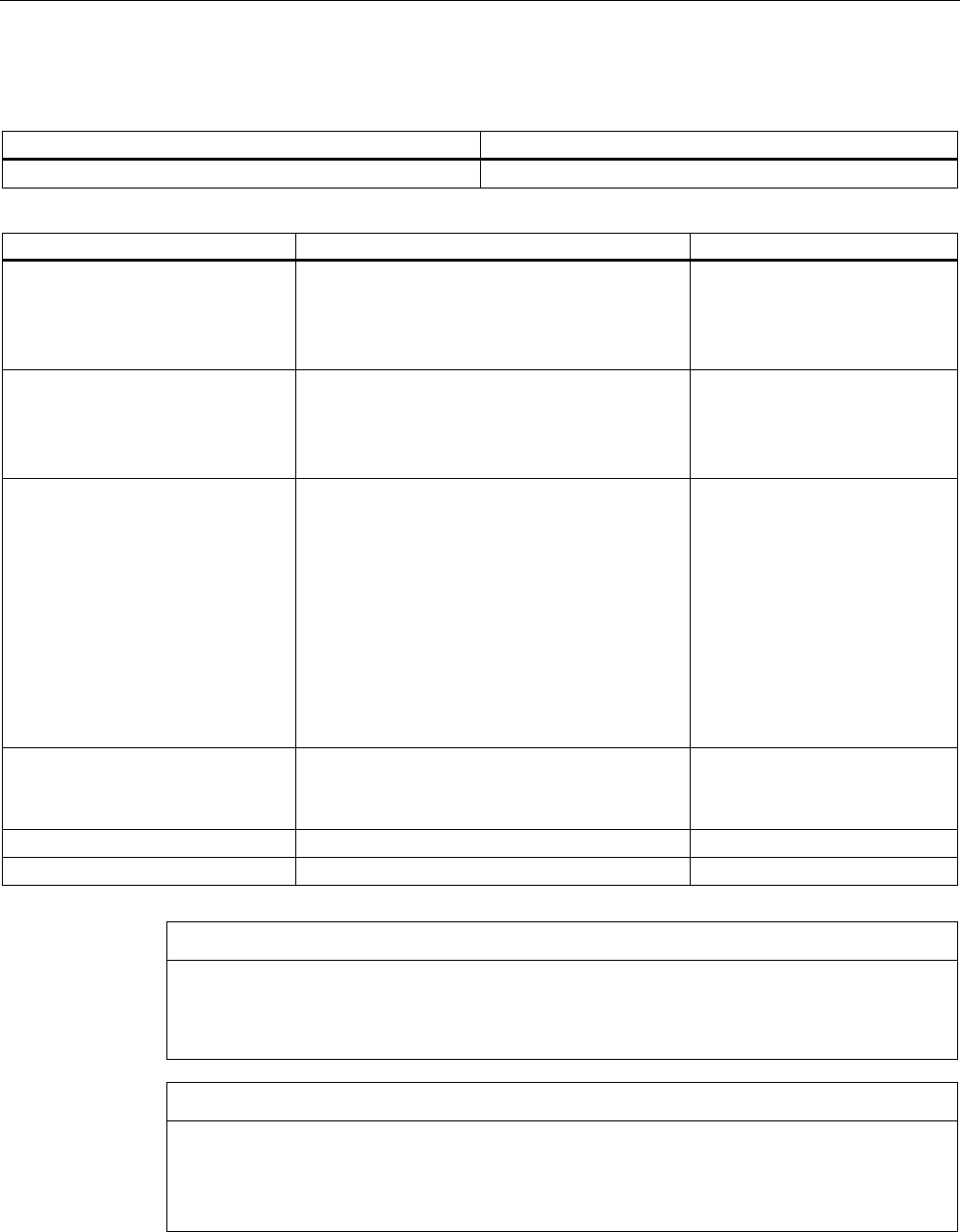
5.3.1.2 Design of the RF660R reader
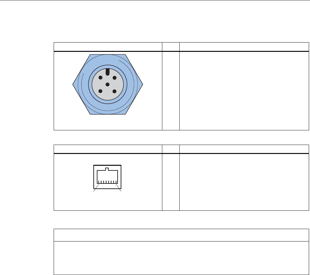
Item Description
(1) Status LED
(2) Industrial Ethernet
(RJ45 socket)
(3) RS 422 interface
(not assigned)
(4) RS 232 interface
(5-pin M12 connector)
(5) Digital I/O
(8-pin M12 connector)
(6) Power, 24 V DC;
(4-pin M12 connector)
Description
4 antenna connections
ANT 1 to ANT 4
(RTNC plug)
Readers
5.3 RF660R reader
SIMATIC RF600
140 System Manual, 12/2009, J31069-D0171-U001-A9-7618
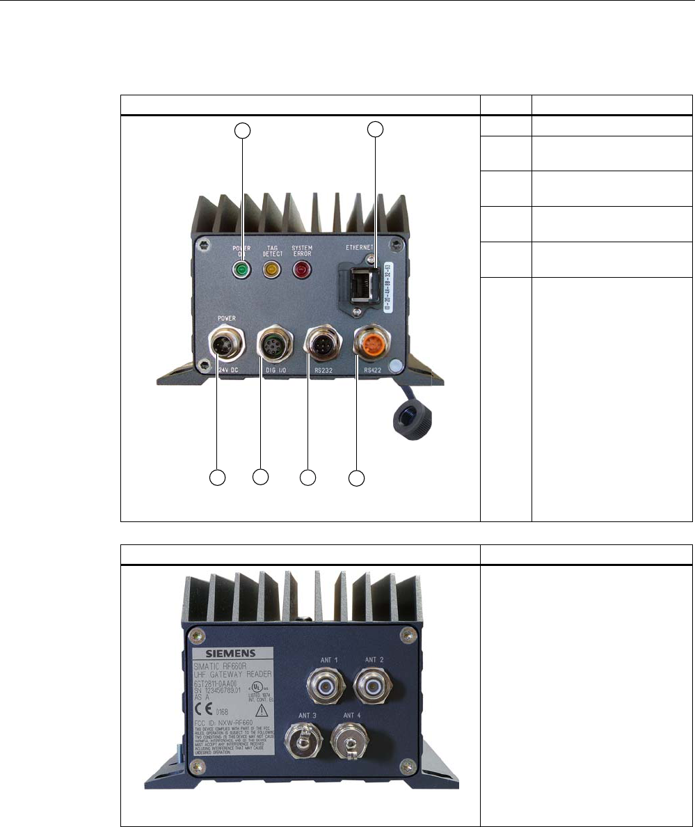
5.3.1.3 Status displays
Status displays LEDs Color Description
Power on Green Power supply ON
Tag
Detect
Yellow LED lit, as soon as at least one tag with a correct tag ID is
within the field.
System
error
Red Reader is not active, a more or less major fault has occurred
In addition, this LED also indicates the fault status through
the number of flashing pulses. Reboot (operating voltage Off
→ On is necessary).
The LED flashes once for the 'INACTIVE' status, rebooting is
not necessary in this case.
Note
If "Tag Detect" is not lit even though a tag is located within the field, common reasons
include:
• Tag protocol has been set incorrectly (can be set with Configuration Software)
• Tag is defective
• Reader or antenna has a defect
• Tag is not in the field of radiation of the transmit antenna
Readers
5.3 RF660R reader
SIMATIC RF600
System Manual, 12/2009, J31069-D0171-U001-A9-7618 141
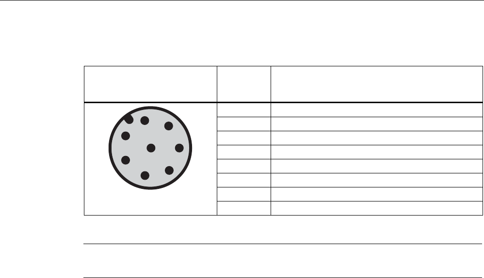
5.3.1.4 Pin assignment of the serial interfaces
RS 232 connector (on reader side) Pin Pin assignment
1
2
3
4
5
RS232_TX
N.C.
N.C.
RS232_RX
GND
Industrial Ethernet (on reader side) Pin Pin assignment
1
2
3
4
5
6
7
8
Transmit Data (+)
Transmit Data (-)
Receive Data (+)
Terminated
Terminated
Receive Data (-)
Terminated
Terminated
NOTICE
We recommend that only original Siemens Ethernet connectors are used (10 m cable:
Order No. 6GT2891-0HN10; 20 m cable: Order No. 6GT2891-0HN20) for connecting to the
Ethernet socket of the reader. If plug-in connectors from other manufacturers are used, it
may be difficult or even impossible to remove the plug from the reader
Readers
5.3 RF660R reader
SIMATIC RF600
142 System Manual, 12/2009, J31069-D0171-U001-A9-7618
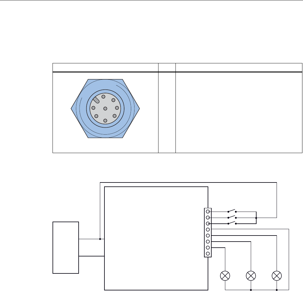
5.3.1.5 Pin assignment and connections of the digital I/O interface
Pin assignment
Digital I/O socket (on reader side) Pin Pin assignment
1
2
3
4
5
6
7
8
Input USER_IN (0)
Input USER_IN (1)
Input USER_IN (2)
GND (IN)
Output USER_OUT (0)
Output USER_OUT (1)
Output USER_OUT (2)
Housing
Connections
9
5)5
'LJLWDO,2
3LQ86(5B,1B
3LQ86(5B,1B
3LQ86(5B,1B
3LQ86(5B287B
3LQ86(5B287B
3LQ86(5B287B
3LQ*1'
9
9
3RZHU
6XSSO\
/RDG /RDG /RDG
Figure 5-10 Connections for digital I/O
Output USER_OUT (0), (1), (2)
● These are high-side switches that connect Vcc (+24 V) to the output ('active high').
● Each output is rated for 0.5 A current and is electronically protected.
● The 0 V rail is Pin 4 (GND).
● Three digital outputs can be operated simultaneously with up to 0.5 A each.
● The outputs are optically isolated through optocouplers.
Readers
5.3 RF660R reader
SIMATIC RF600
System Manual, 12/2009, J31069-D0171-U001-A9-7618 143
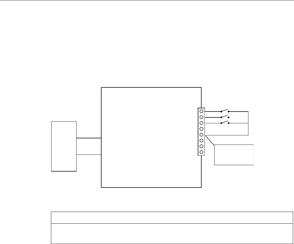
Input USER_IN (0), (1), (2)
● The inputs are optically isolated through optocouplers.
● The 24 V voltage for the digital inputs (e.g. switches, proximity switches) must be
supplied over a separate cable.
● The 24 V voltage for the digital inputs can alternatively be supplied from a digital output
(USER-OUT). In the user program, however, the digital output must be permanently
connected to "1" in this case.
5)5
'LJLWDO,2
3LQ86(5B,1B
3LQ86(5B,1B
3LQ86(5B,1B
3LQ86(5B287B
3LQ86(5B287B
3LQ86(5B287B
3LQ*1'
9
9
3RZHU
6XSSO\
&RQWURO
,QSXWV
VZLWFKHGಱಯ
E\6RIWZDUH
9
Figure 5-11 RF660R connection diagram
NOTICE
It may be necessary to restart the reader
The length of trigger pulses must be longer than 30 ms.
Readers
5.3 RF660R reader
SIMATIC RF600
144 System Manual, 12/2009, J31069-D0171-U001-A9-7618
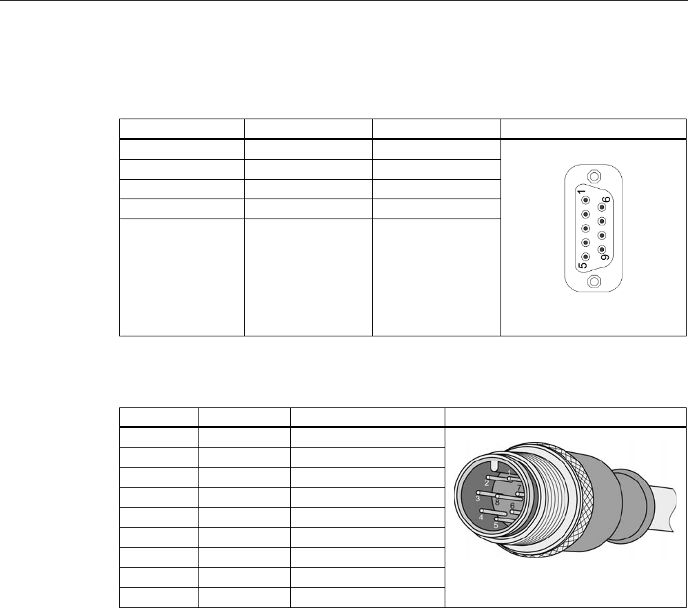
5.3.1.6 Pin assignment of the connecting cable
Table 5- 9 RS 232
Signal M12Pin SUB-D pin Image
TX (reader) 1 2
- 2 -
- 3 -
RX (reader) 4 3
GND 5 5
Table 5- 10 Digital I/O, for cable with open cable ends
M12 pin Core color Pin assignment View of M12 connector
1 white Input USER_IN (0)
2 brown Input USER_IN (1)
3 green Input USER_IN (2)
4 yellow GND
5 Gray Output USER_OUT (0)
6 pink Output USER_OUT (1)
7 blue Output USER_OUT (2)
8 red Housing
Shield Shield
Comment
This cable has an 8-pin M12 connector at one end and the other cable end is 'open'. There
are 8 color-coded single cores there for connecting to external devices. Cable length = 5m.
The cable length can be reduced, if needed.
Readers
5.3 RF660R reader
SIMATIC RF600
System Manual, 12/2009, J31069-D0171-U001-A9-7618 145
5.3.1.7 Power supply
Pin assignment of the power connections
Power connector (on reader side) Pin Pin assignment
1
2
3
4
Ground (0 V)
+24 V
+24 V
Ground (0 V)
5.3.1.8 Grounding connection
A low-impedance earth connection ensures that interference signals generated, for example,
by external power supply cables or signal cables are safely discharged to earth.
Earthing connection
The ground terminal (M4 threads) on the
device (large surface, large-area contact) has
to be connected with the ground conductor of
the plant or the cabinet in which the reader is
to be installed.
The minimum conductor cross-section may
not be less than 2.5 mm2.
Readers
5.3 RF660R reader
SIMATIC RF600
146 System Manual, 12/2009, J31069-D0171-U001-A9-7618
5.3.2 Planning application
Firmware and software compatibility
CAUTION
Damage to the reader
The SIMATIC RF660R reader with firmware version V1.2 must only be configured and
operated with the relevant SIMATIC RF660R Configuration Software V1.2.
The SIMATIC RF660R reader with firmware version V1.3 must only be configured and
operated with the relevant SIMATIC RF660R Configuration Software V1.2 (limited
functionality) or V1.3.
No other combination of firmware and configuration software is permissible. The
configuration software V1.3 recognizes if it has been connected to a SIMATIC RF660R
reader with firmware version V1.3 or version 1.2.
Therefore always refer to the chapter "Firmware/Configuration Software Compatibility" of
the Configuration Manual before you make any changes to the firmware version or the
version of the SIMATIC RF660R Configuration Software.
Compatibility RF-MANAGER versions/reader firmware versions
Below you will find an overview of the compatibility of RF-MANAGER versions and RF660R
reader firmware versions.
In the RF-MANAGER 2008 Service Pack 2, you can select the matching ETSI standard
(ETSI standard EN 302 208 V1.1.1 or EN 302 208 V1.2.1) for your reader RF660R
depending on the firmware version.
For additional information refer to the "RF-MANAGER 2008 Service Pack 2" documentation.
This documentation can be downloaded via the portal .
Older RF-MANAGER versions RF-MANAGER 2008 SP2
Reader firmware version GR_XML_2.0 GR_XML_2.0 GR_XML_3.0
V1.1 X X -
V1.2 Restricted functionality Restricted functionality -
V1.3 X
1) - X
1) No commands may be used that are no longer permitted in firmware V1.3.
See also
Service & Support (Page 350)
Readers
5.3 RF660R reader
SIMATIC RF600
System Manual, 12/2009, J31069-D0171-U001-A9-7618 147
5.3.2.1 Increasing the probability of identification for tags - Antenna switching
To achieve a high probability of reading tags, the antenna switching function has been
implemented in the RF660R reader:
During a defined time period, the reader transmits on one antenna and receives on the other.
As long as the antenna is receiving signals from further tags, the reader continues to
transmit on the same transmitter antenna until all responding tags have been identified.
Subsequently, or if no tags respond, the reader activates another antenna as the transmitter
antenna. After all the antenna have transmitted at least once and no tag has responded, or
when the settling time is excessively long, the reader activates frequency hopping (in the
USA) or channel selection (in Europe).
Cycle 1 Cycle 2 Cycle 3
$17
7; 5;
5;
$17
$17
$17
5; 5;
7;
$17
$17
$17
5; 7;
5;
$17
$17
Antenna 1 transmits
Antennas 2 and 3 receive
Antenna 2 transmits
Antennas 1 and 3 receive
Antenna 3 transmits
Antennas 1 and 2 receive
Readers
5.3 RF660R reader
SIMATIC RF600
148 System Manual, 12/2009, J31069-D0171-U001-A9-7618
5.3.3 Installation /Mounting
Requirement
WARNING
Ensure that the wall or ceiling can hold four times the total weight of the device.
CAUTION
Emitted radiation
The transmitter complies with the requirements of Health Canada and the FCC limit values
for subjecting persons to HF radiation, provided that a minimum spacing of 26 cm exists
between antenna and person. When the antennas are installed, you must therefore ensure
that a minimum spacing of 26 cm is maintained between personnel and antennas.
Mounting/installing the device
The positions of the fixing holes for the device are shown in the section Dimension drawings
(Page 154).
Examples of mounting types
Material Hole diameter Mounting
Concrete
8 mm diameter
60 mm depth
Rawlplug: 8 mm diameter, 50 mm length
Screws: 4 mm diameter, 50 mm length
Plasterboard
(min. 13 mm thick)
14 mm diameter Gravity toggle: 4 mm diameter, 50 mm length
Metal
(min. 2 mm thick)
5 mm diameter
M4 metal screws: 4 mm diameter,
15 mm length
Readers
5.3 RF660R reader
SIMATIC RF600
System Manual, 12/2009, J31069-D0171-U001-A9-7618 149
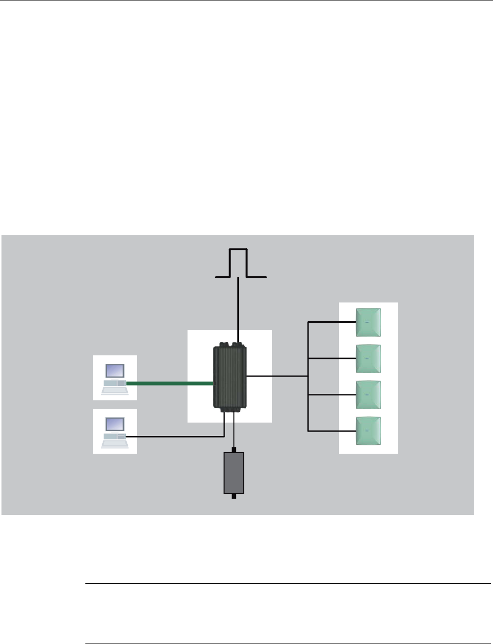
5.3.3.1 Configuration/integration
Configuration
Two communication interfaces are available for integrating the device into system
environments/networks:
● Ethernet and
● RS 232
The communication interfaces transfer the data to IT, ERP and SCM systems on SIMATIC
PLCs or PCs (also used for configuration and diagnostics).
Simple process controls (e.g. a traffic signal) can be directly implemented using the
write/read device via three digital inputs and outputs with 24 V each.
5),'
'HYLFH
'DWD0DQDJHPHQW
3&LQWHUIDFLQJ
IRUFRQILJXUDWLRQ
DQGGLDJQRVWLFV
$QWHQQD
6,0$7,&5)$
5XJJHGKRXVLQJZLWK
KLJKGHJUHHRI
SURWHFWLRQ,3
8SWRDQWHQQDVRQ
RQH5)5UHDGHU
FRQQHFWDEOH
3URFHVVFRQWURO
[GLJLWDOLQSXW9
[GLJLWDORXWSXW9$
3RZHUVXSSO\
5HDGHU
6,0$7,&5)5
8SWRP
IRUHDFKDQWHQQD
9$&
9'&
56
(WKHUQHW7&3,3
Figure 5-12 Configuration overview of the RF660R reader
Note
Maximum cable length for the RS232 interface
For secure and error-free data transmission, a data transfer rate of 115.2 kbit/s applies:
maximum cable length 10 m.

Readers
5.3 RF660R reader
SIMATIC RF600
150 System Manual, 12/2009, J31069-D0171-U001-A9-7618
Transmission protocols
RS232 communication
XML protocol
Transmission rates 115200 bps
Start bits 1
Data bits 8
Parity None
Flow control Xon/Xoff
Stop bits 1
Ethernet communication
The Ethernet interface offers automatic selection between 10BaseT and 100BaseTX.
Shielded Twisted-Pair patch cables with standard RJ45 connectors are recommended for a
reliable connection.
Readers
5.3 RF660R reader
SIMATIC RF600
System Manual, 12/2009, J31069-D0171-U001-A9-7618 151
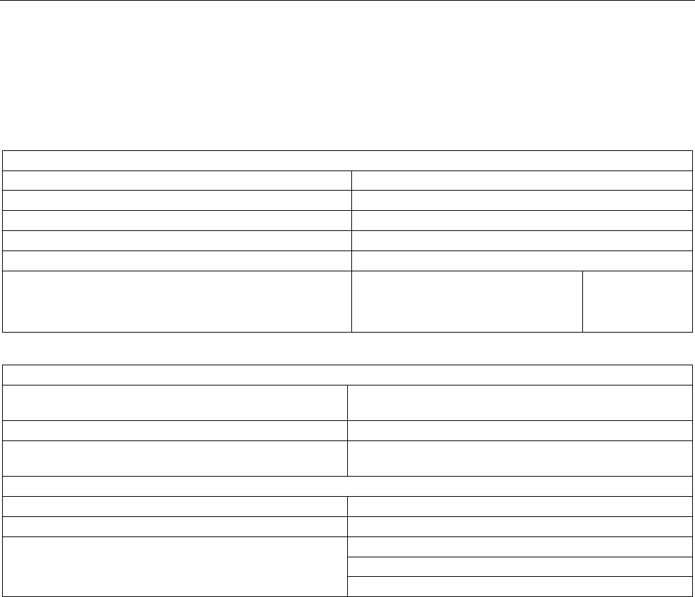
5.3.4 Technical specifications
5.3.4.1 Mechanical data
Mechanical specification of RF660R
Weight 3.7 kg
Dimensions (L x W x H) in mm 320 x 145 x 100 without connections
Material Aluminum
Color Anthracite
MTBF (Mean Time Before Failure) 27,2 years
Power consumption, typical 24 V
• At 2 W transmit power
• No digital outputs active
800 mA
Mechanical environmental conditions
Shock ETSI EN 300 019-2-3 V2.1.2
IEC 60068-2-27
Total shock response spectrum Type 3.3
Vibration ETSI EN 300 019-2-3 V2.1.2
IEC 60068-2-64
Climatic Conditions
Ambient temperature during operation -25 °C to +55 °C
Ambient temperature for transport and storage -40 °C to +85 °C
ETSI EN 301 489-1 / -3
ETSI EN 302 208 V1.2.1
Electromagnetic compatibility
FCC Part 15

Readers
5.3 RF660R reader
SIMATIC RF600
152 System Manual, 12/2009, J31069-D0171-U001-A9-7618
Status displays on the device
Power On Green LED
Tag Detect Yellow LED
System error Red LED
Interfaces
Antenna connections 4x RTNC connector
Maximum number of antenna channels operating
independently of each other
2 (with 2 x 2 antennas, tags can be read by a reader at 2
independent locations)
Ethernet 10BaseT or 100BaseTx 1x RJ45 connection
according to IEEE 802.3 and ISO 8802-3
RS422 Currently unassigned
RS232 1x connector (5-pin M12). Bit rate: 115200 bps
Digital inputs 3 (8-pin M12)
log. "0": 0…7 V
log. "1": 15…24 V
Digital outputs (short-circuit proof) 3 (8-pin M12)
24 V; 0.5 A each
Power supply 24 V DC (4-pin M12) 20 to 30 V (2.2 A)
Approvals • Radio to R&TTE- guidelines EN 300 330, EN 301 489
• CE, EMC, FCC, IC, cULus
• IEC60950, including US and Canadian variants of it
• FCC CFR47 Part 15.247
• Industrial Canada, RSS-210, Issue 6, Sept. 2005
• ETSI EN 302-208 V1.2.1
• Reader degree of protection acc. to EN 60529 (IP65)

Readers
5.3 RF660R reader
SIMATIC RF600
System Manual, 12/2009, J31069-D0171-U001-A9-7618 153
5.3.4.2 Technical data according to EPC and ISO
Frequencies
European frequency band 865 … 868 MHz (4 channels 865.7 MHz; 866.3 MHz;
866.9 MHz; 867.5 MHz without LBT with up to 2 W ERP)
North American frequency band 902 ... 928 MHz (50 channels, frequency hopping)
Frequency band for China 920.125 to 924.875 MHz (16 subchannels at 2 W ERP, 20
subchannels at 0.1 W ERP)
Frequency accuracy max.± 10 ppm
Channel spacing EU: 200 kHz
US: 500 kHz
China: 250 kHz
Modulation methods ASK: DSB modulation & PR-ASK modulation
Encoding, Manchester or Pulse Interval (PIE)
Effective radiant power Europe / China USA
Range 0.1 to 2 W ERP 0.4 to 4 W EIRP =
0.24 to 2.4 W ERP
Reading distance Europe / China USA
Antennas mounted on opposing sides
(portal configuration)
max. 10 m (recommended
maximum value for
configuration)
max. 10 m (recommended
maximum value for
configuration)
Antennas mounted on the same side max. 10 m (recommended
maximum value for
configuration)
max. 10 m (recommended
maximum value for
configuration)
Readers
5.3 RF660R reader
SIMATIC RF600
154 System Manual, 12/2009, J31069-D0171-U001-A9-7618
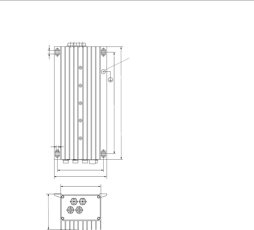
5.3.5 Dimension drawings
*URXQGLQJFRQQHFWLRQ
$OOGLPHQVLRQVLQPP
Figure 5-13 Dimension drawing of the reader
Readers
5.3 RF660R reader
SIMATIC RF600
System Manual, 12/2009, J31069-D0171-U001-A9-7618 155
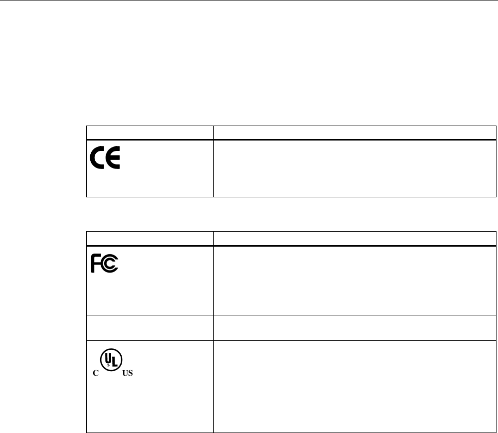
5.3.6 Certificates and approvals
5.3.6.1 CE mark
Table 5- 11 6GT2811-0AA01
Certificate Description
CE approval according to R&TTE guideline
Table 5- 12 FCC IDs: NXW-RF660; IC: 267X-RF660
Standards
Federal Communications
Commission
FCC Title 47, Part 15.sections 15.247
Radio Frequency Interference Statement
This equipment has been tested and found to comply with the limits
for a Class A digital device, pursuant to Part 15 of the FCC Rules.
FCC ID: NXW-RF660
Industry Canada Radio
Standards Specifications
RSS-210 Issue 7, June 2007, Sections 2.2, A8
IC: 267X-RF660
This product is UL-certified for the USA and Canada.
It meets the following safety standard(s):
UL 60950-1 - Information Technology Equipment Safety - Part 1:
General Requirements
CSA C22.2 No. 60950 -1 - Safety of Information Technology
Equipment
UL Report E 205089

Readers
5.3 RF660R reader
SIMATIC RF600
156 System Manual, 12/2009, J31069-D0171-U001-A9-7618
5.3.6.2 FCC information
Siemens SIMATIC RF660R
FCC ID: NXW-RF660
This device complies with part 15 of the FCC rules.
Operation is subject to the following two conditions:
(1) This device may not cause harmful interference, and
(2) This device must accept any interference received, including interference that may cause
undesired operation.
Caution
Any changes or modifications not expressly approved by the party responsible for
compliance could void the user's authority to operate the equipment.
Note
This equipment has been tested and found to comply with the limits for a Class A digital
device, pursuant to part 15 of the FCC Rules. These limits are designed to provide
reasonable protection against harmful interference when the equipment is operated in a
commercial environment. This equipment generates, uses, and can radiate radio frequency
energy and, if not installed and used in accordance with the instruction manual, may cause
harmful interference to radio communications. Operation of this equipment in a residential
area is likely to cause harmful interference in which case the user will be required to correct
the interference at his own expense.
FCC NoticeTo comply with FCC part 15 rules in the United States, the system must be
professionally installed to ensure compliance with the Part 15 certification.
It is the responsibility of the operator and professional installer to ensure that only certified
systems are deployed in the United States. The use of the system in any other combination
(such as co-located antennas transmitting the same information) is expressly forbidden.
FCC Exposure InformationTo comply with FCC RF exposure compliance requirements, the
antennas used for this transmitter must be installed to provide a separation distance of at
least 20 cm from all persons and must not be co-located or operating in conjunction with any
other antenna or transmitter.
5.3.6.3 IC-FCB information
Siemens SIMATIC RF660R
IC: 267X-RF660
Industry Canada NoticeTo reduce potential radio interference to other users, the antenna
type and its gain should be so chosen that the equivalent isotropically radiated power
(e.i.r.p.) is not more than that permitted for successful communication.
This device has been designed to operate with the SIMATIC RF620A antenna 902-928 as
well as the SIMATIC RF660A antenna 902-928 listed below, and having a maximum gain of
5,5 dBi.
Other antennas or antennas having a gain greater than 5,5 dBi are strictly prohibited for use
with this device.
The required antenna impedance is 50 Ohms.