Siemens Gigaset 504 Agu Instruction Manual
2014-12-11
: Siemens Siemens-Gigaset-504-Agu-Instruction-Manual-121376 siemens-gigaset-504-agu-instruction-manual-121376 siemens pdf
Open the PDF directly: View PDF ![]() .
.
Page Count: 93
- Contents
- The product series Gigaset 501/504
- The device
- Installing the device
- The user interface
- Configuring Advanced Settings
- Administration
- Status information
- Appendix
- Glossary
- Index
Dca[m_n ~}=>DR
Dca[m_n
2
Contents
Contents
The product series Gigaset 501/504 . . . . . . . . . . . . . 4
Do your part for the environment (ECO) . . . . . . . . . . . . . . . . . . . . . . . . . . . . . . . . . . . . 5
Features and applications . . . . . . . . . . . . . . . . . . . . . . . . . . . . . . . . . . . . . . . . . . . . . . . 5
The device . . . . . . . . . . . . . . . . . . . . . . . . . . . . . . . . . . 7
Operating elements . . . . . . . . . . . . . . . . . . . . . . . . . . . . . . . . . . . . . . . . . . . . . . . . . . . . 7
LED panel . . . . . . . . . . . . . . . . . . . . . . . . . . . . . . . . . . . . . . . . . . . . . . . . . . . . . . . . . . . .8
Ports on the rear panel . . . . . . . . . . . . . . . . . . . . . . . . . . . . . . . . . . . . . . . . . . . . . . . . . 9
Bottom . . . . . . . . . . . . . . . . . . . . . . . . . . . . . . . . . . . . . . . . . . . . . . . . . . . . . . . . . . . . . 10
System requirements . . . . . . . . . . . . . . . . . . . . . . . . . . . . . . . . . . . . . . . . . . . . . . . . . . 11
Installing the device . . . . . . . . . . . . . . . . . . . . . . . . 12
Overview of the installation steps . . . . . . . . . . . . . . . . . . . . . . . . . . . . . . . . . . . . . 12
Setting up the router Gigaset 504 AGU . . . . . . . . . . . . . . . . . . . . . . . . . . . . . . . . . 12
Connecting to the splitter data port . . . . . . . . . . . . . . . . . . . . . . . . . . . . . . . . . . . 13
Wired connection to the PC . . . . . . . . . . . . . . . . . . . . . . . . . . . . . . . . . . . . . . . . . . 15
Connecting to the mains power supply . . . . . . . . . . . . . . . . . . . . . . . . . . . . . . . . . 16
Checking the operating state . . . . . . . . . . . . . . . . . . . . . . . . . . . . . . . . . . . . . . . . . 16
Making the basic settings . . . . . . . . . . . . . . . . . . . . . . . . . . . . . . . . . . . . . . . . . . . 16
Network configuration of the PCs . . . . . . . . . . . . . . . . . . . . . . . . . . . . . . . . . . . . . . . . 17
The user interface . . . . . . . . . . . . . . . . . . . . . . . . . . 18
Starting the user interface . . . . . . . . . . . . . . . . . . . . . . . . . . . . . . . . . . . . . . . . . . . . . . 18
The start screen . . . . . . . . . . . . . . . . . . . . . . . . . . . . . . . . . . . . . . . . . . . . . . . . . . . . . . 19
Selecting a language . . . . . . . . . . . . . . . . . . . . . . . . . . . . . . . . . . . . . . . . . . . . . . . . . . 20
Connecting to the Internet manually . . . . . . . . . . . . . . . . . . . . . . . . . . . . . . . . . . . . . 20
Elements in the user interface . . . . . . . . . . . . . . . . . . . . . . . . . . . . . . . . . . . . . . . . . . . 21
Configuring Advanced Settings . . . . . . . . . . . . . . . 22
Internet . . . . . . . . . . . . . . . . . . . . . . . . . . . . . . . . . . . . . . . . . . . . . . . . . . . . . . . . . . . .23
Internet selection . . . . . . . . . . . . . . . . . . . . . . . . . . . . . . . . . . . . . . . . . . . . . . . . . . 23
Internet Connection . . . . . . . . . . . . . . . . . . . . . . . . . . . . . . . . . . . . . . . . . . . . . . . . 25
Firewall . . . . . . . . . . . . . . . . . . . . . . . . . . . . . . . . . . . . . . . . . . . . . . . . . . . . . . . . . . . . .28
Setting up access control to the Internet . . . . . . . . . . . . . . . . . . . . . . . . . . . . . . . . 28
Setting up the NAT function . . . . . . . . . . . . . . . . . . . . . . . . . . . . . . . . . . . . . . . . . . . . 30
Port Forwarding . . . . . . . . . . . . . . . . . . . . . . . . . . . . . . . . . . . . . . . . . . . . . . . . . . . 32
Opening the firewall for a selected PC (Exposed Host) . . . . . . . . . . . . . . . . . . . . . 34
Dynamic DNS . . . . . . . . . . . . . . . . . . . . . . . . . . . . . . . . . . . . . . . . . . . . . . . . . . . . . 35
Qos (Quality of Service) . . . . . . . . . . . . . . . . . . . . . . . . . . . . . . . . . . . . . . . . . . . . . 36
LAN configuration . . . . . . . . . . . . . . . . . . . . . . . . . . . . . . . . . . . . . . . . . . . . . . . . . . . . 37
Assigning static IP addresses to individual PCs . . . . . . . . . . . . . . . . . . . . . . . . . . . 38
3
Contents
Configuring wireless connections . . . . . . . . . . . . . . . . . . . . . . . . . . . . . . . . . . . . . . . . 39
Setting encryption . . . . . . . . . . . . . . . . . . . . . . . . . . . . . . . . . . . . . . . . . . . . . . . . . 41
WPA2-PSK and WPA-PSK/WPA2-PSK . . . . . . . . . . . . . . . . . . . . . . . . . . . . . . . . . . . . 41
WEP encryption . . . . . . . . . . . . . . . . . . . . . . . . . . . . . . . . . . . . . . . . . . . . . . . . . . . 42
Connecting PCs wirelessly . . . . . . . . . . . . . . . . . . . . . . . . . . . . . . . . . . . . . . . . . . . 44
Permitted clients . . . . . . . . . . . . . . . . . . . . . . . . . . . . . . . . . . . . . . . . . . . . . . . . . . 45
Repeater function (WDS) . . . . . . . . . . . . . . . . . . . . . . . . . . . . . . . . . . . . . . . . . . . . 46
Administration . . . . . . . . . . . . . . . . . . . . . . . . . . . . . 49
Regional Options . . . . . . . . . . . . . . . . . . . . . . . . . . . . . . . . . . . . . . . . . . . . . . . . . . . . . 49
System Password . . . . . . . . . . . . . . . . . . . . . . . . . . . . . . . . . . . . . . . . . . . . . . . . . . . . . 50
System management . . . . . . . . . . . . . . . . . . . . . . . . . . . . . . . . . . . . . . . . . . . . . . . . . . 51
Backing up and restoring a configuration . . . . . . . . . . . . . . . . . . . . . . . . . . . . . . . . . . 52
Backing up configuration data . . . . . . . . . . . . . . . . . . . . . . . . . . . . . . . . . . . . . . . . 53
Restoring the saved data . . . . . . . . . . . . . . . . . . . . . . . . . . . . . . . . . . . . . . . . . . . . 53
Restoring factory settings . . . . . . . . . . . . . . . . . . . . . . . . . . . . . . . . . . . . . . . . . . . 53
Reboot . . . . . . . . . . . . . . . . . . . . . . . . . . . . . . . . . . . . . . . . . . . . . . . . . . . . . . . . . . . . .53
Updating firmware . . . . . . . . . . . . . . . . . . . . . . . . . . . . . . . . . . . . . . . . . . . . . . . . . . . . 54
System Log . . . . . . . . . . . . . . . . . . . . . . . . . . . . . . . . . . . . . . . . . . . . . . . . . . . . . . . . . . 55
Status information . . . . . . . . . . . . . . . . . . . . . . . . . . 56
Overview . . . . . . . . . . . . . . . . . . . . . . . . . . . . . . . . . . . . . . . . . . . . . . . . . . . . . . . . . . . 56
Security . . . . . . . . . . . . . . . . . . . . . . . . . . . . . . . . . . . . . . . . . . . . . . . . . . . . . . . . . . . .57
Internet . . . . . . . . . . . . . . . . . . . . . . . . . . . . . . . . . . . . . . . . . . . . . . . . . . . . . . . . . . . .58
Local Network . . . . . . . . . . . . . . . . . . . . . . . . . . . . . . . . . . . . . . . . . . . . . . . . . . . . . . . 59
Wireless Network . . . . . . . . . . . . . . . . . . . . . . . . . . . . . . . . . . . . . . . . . . . . . . . . . . . . . 60
Device . . . . . . . . . . . . . . . . . . . . . . . . . . . . . . . . . . . . . . . . . . . . . . . . . . . . . . . . . . . . . .61
Appendix . . . . . . . . . . . . . . . . . . . . . . . . . . . . . . . . . . 62
Troubleshooting . . . . . . . . . . . . . . . . . . . . . . . . . . . . . . . . . . . . . . . . . . . . . . . . . . . . . . 62
Local area networks with Gigaset products . . . . . . . . . . . . . . . . . . . . . . . . . . . . . . . . . 66
Wired local area network (Ethernet) . . . . . . . . . . . . . . . . . . . . . . . . . . . . . . . . . . . 67
Wireless local area network (WLAN) . . . . . . . . . . . . . . . . . . . . . . . . . . . . . . . . . . . 68
Linking a wireless network to an Ethernet . . . . . . . . . . . . . . . . . . . . . . . . . . . . . . 70
Extending the wireless network coverage with a repeater . . . . . . . . . . . . . . . . . . 71
Deactivating HTTP proxy and configuring a pop-up blocker . . . . . . . . . . . . . . . . . . . . 72
Deactivating the HTTP proxy . . . . . . . . . . . . . . . . . . . . . . . . . . . . . . . . . . . . . . . . . 72
Configuring the pop-up blocker . . . . . . . . . . . . . . . . . . . . . . . . . . . . . . . . . . . . . . 72
Specifications . . . . . . . . . . . . . . . . . . . . . . . . . . . . . . . . . . . . . . . . . . . . . . . . . . . . . . . . 74
Authorisation . . . . . . . . . . . . . . . . . . . . . . . . . . . . . . . . . . . . . . . . . . . . . . . . . . . . . . . . 75
Glossary . . . . . . . . . . . . . . . . . . . . . . . . . . . . . . . . . . 76
Index . . . . . . . . . . . . . . . . . . . . . . . . . . . . . . . . . . . . . 89
4
The product series Gigaset 501/504
The product series Gigaset 501/504
The devices of the product series Gigaset 501/504 are powerful but easy-to-use commu-
nication devices for connecting your PC or local area network (LAN) to the Internet. They
contain an integrated ADSL modem (ADSL /ADSL2+), allowing you easy access to the
Internet.
With the router Gigaset 504 you can also connect a set-top box to watch IPTV, if this is
supported by your Internet service provider.
You can connect your PC via cable or wirelessly and create a wired local network (LAN)
or wireless local area network (WLAN). For network security, wireless transmission can
be encrypted using the WPA/WPA2 standard or 64/128-bit WEP.
Your device allows several users to access the Internet simultaneously. A single user
account can be shared if your Internet service provider permits this. If you want to surf
the Internet, watch IPTV and make calls using the Internet at the lowest possible cost,
the Gigaset devices are a convenient and simple solution.
The devices have an extensive range of functions but remain simple to use. They can be
configured and operational within a few minutes.

5
The product series Gigaset 501/504
Do your part for the environment (ECO)
Thanks to a switch-mode power supply unit, all of our broadband prod-
ucts offer significantly reduced power consumption - for more energy-
efficient use, which helps make a cleaner environment for everyone.
You can turn the WLAN off completely when you're not using it. It's our
goal to ensure a sustainable economic process by using an environmentally friendly pro-
duction and management system - which makes it easy for us to meet the strict ISO
14001 standards for international environmental management.
Features and applications
The router Gigaset 504 AGU's wide range of features makes it ideal for a large number
of applications.
Depending on your device, some of the features may differ from the description in this
instruction manual.
uInternet access
The router supports shared Internet access for up to 252 users via the integrated
ADSL /ADSL2+ modem. This means several users in your network can surf the Inter-
net at the same time, all using the same Internet account.
uSetting up a local area network
The router offers the following possibilities:
– Depending on the device up to four devices connected via Ethernet ports with a
transmission speed of 10 or 100 Mbps (with automatic recognition).
– Up to 252 mobile terminals connected via a radio interface with a transmission
speed of up to 54 Mbps. It complies with IEEE 802.11g standard and can work
with all products that satisfy Standard IEEE 802.11b or 802.11g.
– Using the router Gigaset 504 AGU makes it easy to set up a network at home or
in small offices. For example, users can exchange data or share resources in the
network, such as a file server or printer.
– The router Gigaset 504 AGU supports DHCP for dynamic IP configuration of the
local area network, and DNS for domain name mapping.
An introduction into the various options of establishing a local network can be found
in the appendix in section "Local area networks with Gigaset products" on page 66.
uSecurity functions
The router Gigaset 504 AGU offers comprehensive security features:
–Firewall protection against unauthorised access from the Internet
All PCs in the local area network use the Public IP address of the router to establish
Internet connections, making them 'invisible' to other Internet users. The router
only allows access from the Internet if it has been requested from the local area
network.
Thanks to the firewall, the router also offers comprehensive protection against
attacks from computer hackers.
6
The product series Gigaset 501/504
– Service filtering and URL blocking
The router can filter Internet access, allowing you to determine which PCs may
access which Internet services.
You can also deactivate access to certain Internet domains and sites (URL block-
ing).
– Access control and encryption for the local area network
You can use various encryption methods and authentication methods (WEP, WPA/
WPA2-PSK, WPA/WPA2, MAC access control) to prevent unauthorised access to
your wireless LAN or to make data illegible to unauthorised parties. The security
settings available to you depend on the components used in your local network.
With MAC access control you can allow wireless access to selected PCs.
uOffering your own services on the Internet
– If you want to offer your own services on the Internet, you can set up the router
as a virtual server without permitting further access to the local area network.
–DMZ (Exposed Host)
This allows you to release a PC in your local area network for unlimited access
from the Internet. Note that in this case your local area network will no longer be
adequately protected against Internet attacks.
7
The device
The device
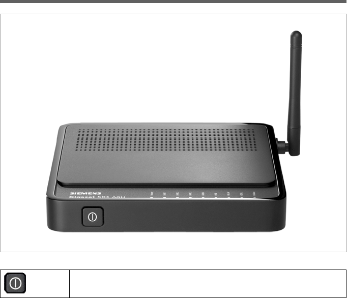
Operating elements
Button to switch the device on and off.
8
The device
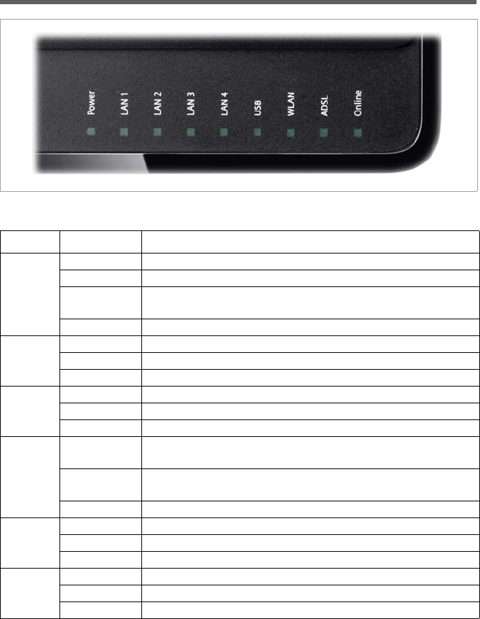
LED panel
The LEDs (from left to right) have the following functions:
LED State Status
Power
On (green) The router is connected to the mains.
Flashing Firmware update is running.
Frequently
flashing
Self-test failure. Device is not bootable or device malfunc-
tion.
Off The router is disconnected from the mains.
LAN /
LAN1 –
LAN4
On A device is connected to the relevant LAN port.
Flashing The relevant LAN port is sending or receiving data (traffic).
Off There is no device connected.
USB
On (green) A device is connected to the router via the USB port.
Flashing The USB port is sending or receiving data.
Off There is no device connected.
WLAN
On The radio interface is activated, no data transmission at
present.
Flashing The router is sending or receiving data on the radio inter-
face.
Off The radio interface is deactivated.
ADSL
On A DSL connection is established.
Flashing The DSL line is being synchronised.
Off DSL is deactivated.
Online
On Connection to the Internet has been established.
Flashing Data is being sent to or received from the Internet.
Off There is no Internet connection.
9
The device
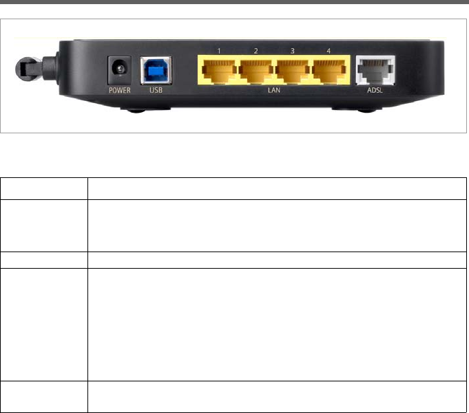
Ports on the rear panel
The rear panel of the router houses the ports.
Element Description
POWER Socket for the mains adapter supplied
Warning: Using the wrong power supply unit may damage the
router.
USB USB port for connecting a PC via USB cable.
LAN1 – LAN4
(yellow)
Four 10/100 Mbps switch ports with automatic recognition (RJ-45).
You can connect up to four devices with Ethernet ports (such as PCs,
a Hub or Switch).
You can connect an external modem (e.g. a VDSL or cable modem)
to the LAN1 port. The integrated ADSL modem is then deactivated.
You will find additional information on the configuration settings on
page 23.
ADSL
(grey)
DSL socket for connecting the integrated modem to the DSL port of
the splitter
10
The device
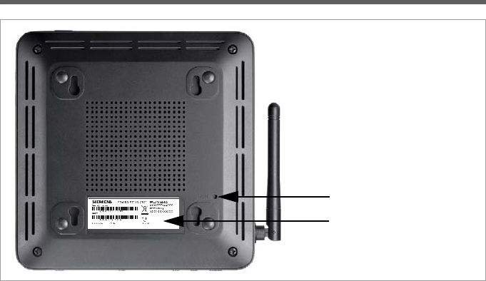
Bottom
Reset button
The underside of the router houses the reset button providing the following functions:
Label
On the label you will find the serial number of your device.
Reboot function: Press and hold the button behind the opening for more than 1 sec-
ond but less than 5 seconds to reboot the device. This does not
affect the configuration settings.
Reset function: Press and hold the button behind the opening for at least 5 sec-
onds to return all settings to factory settings. Warning: This will
clear all the configuration settings you have made since the initial
startup. Updated firmware will not be affected.
Reset button
Label

11
The device
System requirements
You require the following components to operate your router Gigaset 504 AGU:
uA PC with
– an 802.11g or 802.11b compatible wireless Network adapter.
or
–an Ethernet port (10Base-T or 100Base-TX)
uA Web browser such as Microsoft Internet Explorer V 6.0 or higher or Mozilla Firefox
V 1.0 or higher for configuring your router.
uTo access the Internet you require
– a DSL port (splitter),
– the access data for your Internet service provider.
Trademarks
Gigaset Communications GmbH is a trademark licensee of Siemens AG.
Microsoft, Windows 98/SE, Windows ME, Windows 2000, Windows XP, Windows Vista
and Internet Explorer are registered trademarks of the Microsoft Corporation.
Mozilla Firefox is a registered trademark of the Mozilla Organisation.
Note:
An 802.11b-compatible network adapter has a maximum transmission speed of
11 Mbps. An 802.11g-compatible network adapter has a maximum transmission
speed of 54 Mbps.
Note:
We recommend you use a PC with the Windows Vista or Windows XP operating
system because only then are all system requirements for using the device ful-
filled.
For experienced users
The default settings for the router Gigaset 504 AGU are:
– IP address: 192.168.254.254
– Subnet mask: 255.255.255.0
–WLAN: Off
– SSID: AlShamil
– Radio channel: 1 or automatic
– System password: admin

12
Installing the device
Installing the device
Overview of the installation steps
1. First install an Ethernet network card in the PCs you want to connect to the router
Gigaset 504 AGU. The installation is described in the user guides for these products.
2. Then make the necessary connections (PCs, splitter) on the router Gigaset 504 AGU
and activate the device (page 15).
3. Then configure the router Gigaset 504 AGU to activate the device's Internet access
(refer to the section entitled "Internet" on page 23). To do this you will need the ac-
cess data for your Internet service provider.
4. If you wish to use other functions of the router Gigaset 504 AGU, for example the
comprehensive security features, use the Advanced Settings (page 22).
Setting up the router Gigaset 504 AGU
The router can be set up in any suitable location in the home or office. You do not need
any special wiring. However, you should comply with the following guidelines:
uOperate the router only indoors within a temperature range of 0 to +40 °C. Do not
position the router near sources of heat. Do not cover the ventilation slots. High
temperatures can damage the device.
uA mains socket for 220/230 V~ and a connection socket for the splitter or LAN must
be available in the place where you set up the router.
uDo not position the device in the immediate vicinity of stereo equipment, TV sets,
microwave ovens or the like. This may cause interference.
uPosition the router so that it is as near to the centre of your wireless network as pos-
sible. The general rule is: The higher you place the antenna, the better the perform-
ance. Make sure that the place where you position the router offers optimum recep-
tion throughout the house, apartment or office.
uMake sure the router cannot fall down, as this could damage the antenna. Position
the router on a non-slip surface.
uDo not place the router on any furniture surface that could be affected by the heat
from the device.
uLay the cables so that nobody can trip over them. You should not cover the cables
with anything.
Note:
Before the PCs can communicate with the router and with each other in a local net-
work, you may have to change your network settings (see page 17). Configure these
network settings on one PC first so that it can establish a connection to the router. You
can then use this PC to configure the device. To find out how to do this, refer to the
document entitled "Configuring the local area network" on the CD-ROM.
13
Installing the device
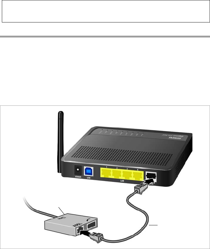
Connecting to the splitter data port
You can operate the router in two different operating modes in order to set up an Inter-
net connection:
– with an integrated ADSL modem
– with an external modem, such as a VDSL or cable modem
Using the integrated ADSL modem
ìConnect the ADSL port (grey) on the router to the ADSL socket on the splitter. To do
this, use the DSL cable supplied (grey).
Please remember:
Network connections (LAN) via cables and telephone lines may only be set up with
the router within enclosed rooms.
Splitter
ADSL cable (grey)
14
Installing the device
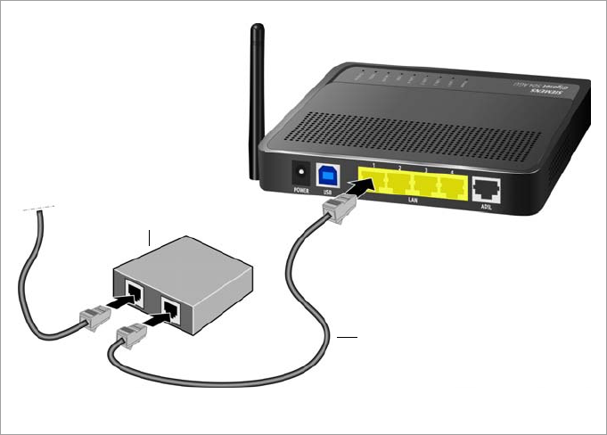
Using an external modem
In this case the LAN1 port is used as WAN port. The integrated ADSL modem is then
deactivated.
ìConnect the LAN1 port on the router with an external modem. To do this, use the
cable supplied with your modem or any Ethernet straight cable having an RJ45 con-
nector on both sides.
ìThen connect this modem to the relevant communications port (e.g. splitter).
To put the LAN port into operation for a WAN connection you have to change the Con-
nection type of the Internet connection to Ethernet (see page 23).
Modem
Ethernet cable
15
Installing the device
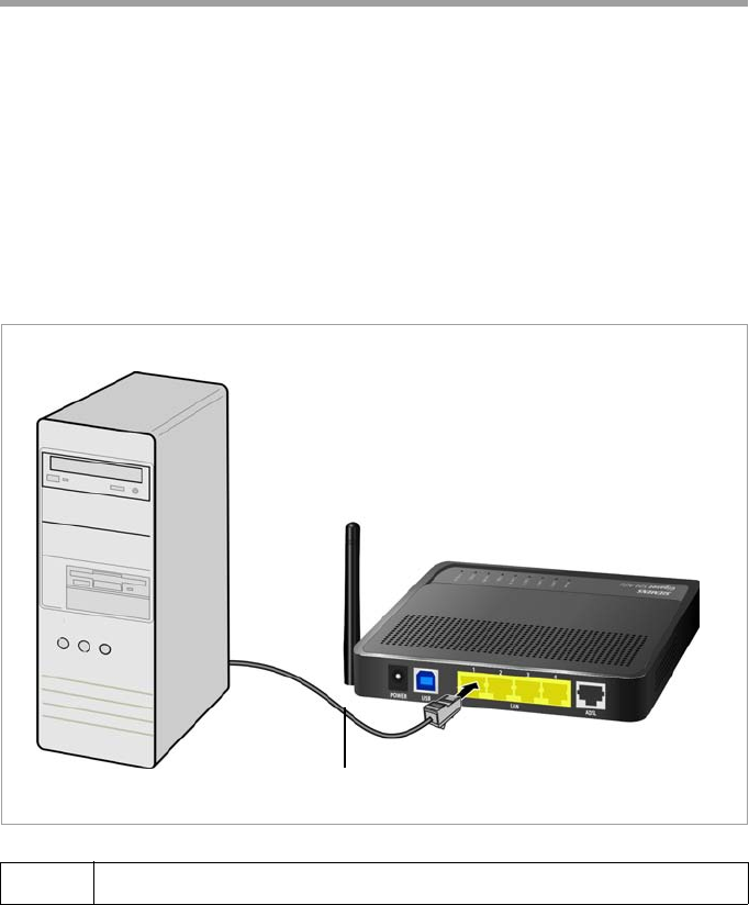
Wired connection to the PC
You can connect wired or wireless PCs to your router to create a local area network
(LAN).
First connect just one PC to the router via cable. You can then carry out the general con-
figuration.
Wireless connection is possible after completing the installation of the router and
switching on the WLAN function via the configuration program. You will find informa-
tion about this topic in the chapter "Configuring wireless connections" on page 39.
ìConnect one of the LAN ports (LAN1 – LAN4, yellow) on the router to the Ethernet
network card in your PC. To do this, use the LAN cable supplied
(CAT5, yellow).
iAlternatively you can also connect a PC via the USB port (blue).
LAN cable (yellow)
16
Installing the device
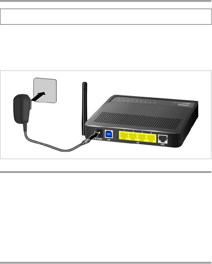
Connecting to the mains power supply
ìConnect the mains adapter cable to the POWER socket on the router.
ìPlug the mains adapter into a mains socket.
ìSwitch on the device.
The router is now switched on and ready for operation.
Checking the operating state
Your router Gigaset 504 AGU is now ready for use. The LED displays on the front panel
of the router provide information about the operating state (see page 8).
When the device is ready for use, the LEDs light up as follows:
uThe Power LED on the front lights up.
uThe ADSL LED flashes to indicate that the DSL connection is being synchronised.
Once this process is complete, the ADSL LED lights up permanently.
uThe LAN LEDs light up if a device is connected to the corresponding LAN port.
uThe USB LED lights up if a device is connected to the USB port.
If this is not the case, refer to the section entitled Troubleshooting on (page 62).
Making the basic settings
You can now make the basic settings for Internet access using the user interface of the
router (page 18).
Please remember:
Only use the mains adapter supplied with the device (9 V DC, 1 A).

17
Installing the device
Network configuration of the PCs
In order to communicate via the router Gigaset 504 AGU, the network configuration
may have to be set up on the connected PCs.
This usually takes place automatically provided you have not made any changes to the
standard settings for the network configuration and you use one of the following oper-
ating systems:
uWindows Vista
uWindows XP
uWindows 2000
With Windows 98/SE, you have to carry out the network configuration.
The description of the network configuration can be found on the CD-ROM.
18
The user interface
The user interface
You have connected a PC to the router Gigaset 504 AGU and possibly made the settings
in the local area network. You can now configure the router using this PC from the user
interface of the router. As Internet browser we recommend Microsoft Internet Explorer
V 6.0 or higher, or Mozilla Firefox V 1.0 or higher.
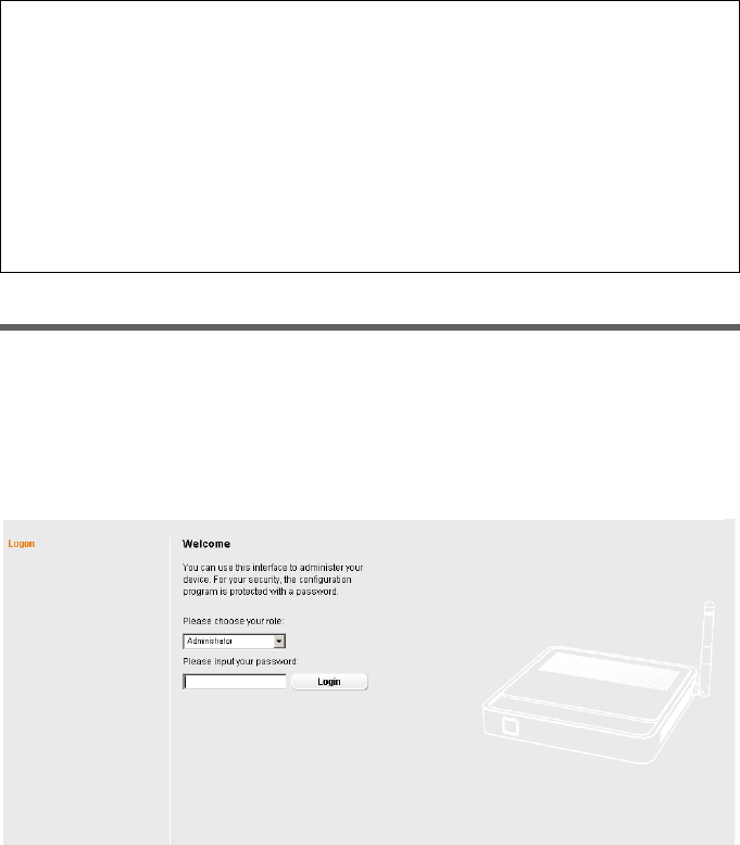
Starting the user interface
To access the user interface of the router Gigaset 504 AGU:
ìStart your Internet browser.
ìEnter the IP address of the router in the browser's address field:
http://192.168.254.254
The login screen appears:
For your security, the configuration program is protected with a password. The default
password generally required is admin. This may differ depending on the provider set-
tings. If necessary, check the details on the device label.
Note:
To start the configuration environment, you may need to deactivate the HTTP proxy
for your browser.
If you use Window Vista or Windows XP Service Pack 2, you will need to configure the
popup blocker.
You will find additional information on these two points on "Deactivating HTTP proxy
and configuring a pop-up blocker" on page 72.
If you use a firewall, it must allow connection to the router. For details, refer to the
user guide for your firewall. If necessary, deactivate the firewall before you configure
your router. You can re-activate the firewall afterwards.
19
The user interface
ìEnter the password.
ìClick Login.
A page with security information will appear. If you carry out all the general and security
settings using the user interface, your device and network will be fully protected. If not,
the next time you log on you will be informed of security gaps in the configuration pro-
gram.
ìClick OK.
The start screen is displayed.
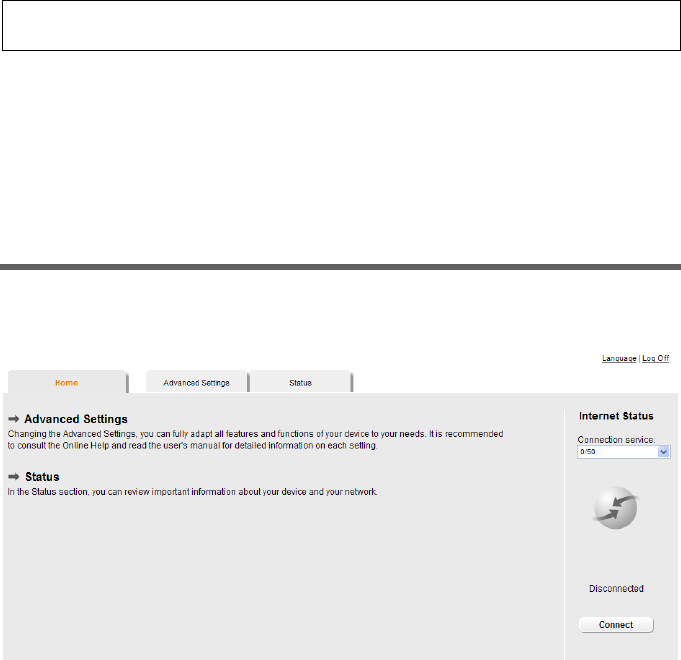
The start screen
The start screen is the starting point for all configuration and administration proce-
dures.
Start screen functions
You can start the following actions on the start screen:
uSelect the language for the user interface (page 20).
uWhen you have configured an Internet connection for the first time, you can view
the selected connection service and the status of the Internet connection, choose a
different connection service and set up or close an Internet connection (page 20).
The start screen shows the status and also the Connect or Disconnect button.
uOpen the Status menu to obtain status information about the router (page 56).
uOpen the Advanced Settings menu for additional configuration options (page 22).
You can call up the Advanced Settings menu and Status information at any time and
on any user interface screen using the tabs at the upper margin of the user interface.
Note:
For security reasons you should change this password at a later stage (page 50).
20
The user interface
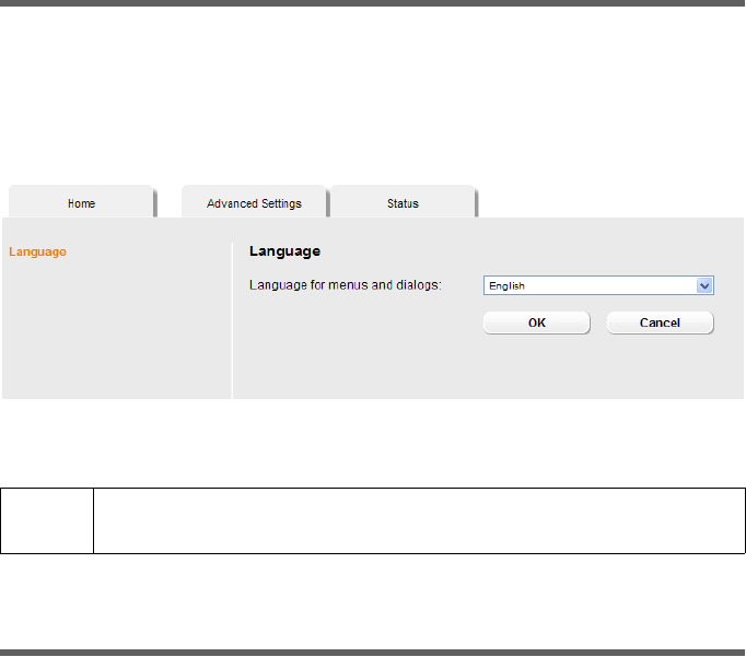
Selecting a language
The user interface exists in various languages. The language modules available are
located on the CD supplied. If you wish to change the preset language, proceed as fol-
lows:
ìInsert the CD into the CD drive of your PC.
ìClick Language at the top right of the start screen.
ìSelect the new language you require from the list.
ìClick OK to load the desired language.
Once the procedure has been concluded, the start screen will be displayed again.
Connecting to the Internet manually
Once you have configured your Internet access (see page 25), you can establish a man-
ual connection to the Internet on the start screen if you have selected Connect on
demand or Connect manually as the Connection mode.
To establish or end an Internet connection manually:
ìOpen the start screen of the router as described on page 18.
If you have already started the user interface, click the start screen tab at the top left
of the window.
If you have not yet started the user interface, do so now and log on.
ìClick Connect to establish a connection to the Internet.
ìClick Disconnect if you no longer require the connection.
!Do not switch off the device during loading, as this could render your
device inoperative.

21
The user interface
Elements in the user interface
The user interface screens contain the following elements:
Help
Log Off button
The Log Off button is always displayed on the right of the user interface. If you click Log
Off, the session is ended and the login screen appears again.
Buttons in the Advanced Settings menu
Other buttons may be displayed depending on the function in question. These are
explained in the relevant sections.
Click this tab top right on the screen to display explanations about
the current user interface screen.
OK Transfers the settings you have made to the router configuration.
Cancel Deletes all the entries on a screen since the last time you clicked OK.

22
Configuring Advanced Settings
Configuring Advanced Settings
In the Advanced Settings menu, you can configure all the options for the router
Gigaset 504 AGU. The following table contains the options available in this menu.
Menu Description
Internet This menu comprises all the setting options relating to the
Internet. In particular, you can do the following:
uCheck and change the configuration for Internet access
(page 25),
uConfigure the firewall, i.e. a number of security and special
functions, for example access control from local PCs to the
Internet or the blocking of certain Web sites (page 28),
uMake the NAT settings required to provide your own serv-
ices on the Internet (page 30),
uSet up dynamic DNS for a fixed Internet address on the
device (page 35),
uConfigure the Quality of Service (QoS) (page 36).
Local Network You can change the Private IP address of the router here and
make settings on the DHCP server (page 37).
Wireless Network You can configure the options for wireless communication
(SSID and encryption) here and restrict access to the router
(page 39).
Administration You can make or change various system settings here, for
example change the password (page 50), set the time
(page 49) or activate remote management (page 51).
In addition, you can also back up the data on the router or
update the firmware (page 52).
23
Configuring Advanced Settings
Internet
If you have configured the router Gigaset 504 AGU using the Gigaset Installer, you have
also configured the WAN connection (Internet access). You can check or change these
settings in the Internet menu.
This menu also offers you a wide range of possibilities for setting up security settings
and limiting access to the Internet as well as for providing your own services on the
Internet.
You can carry out the following via the Internet menu:
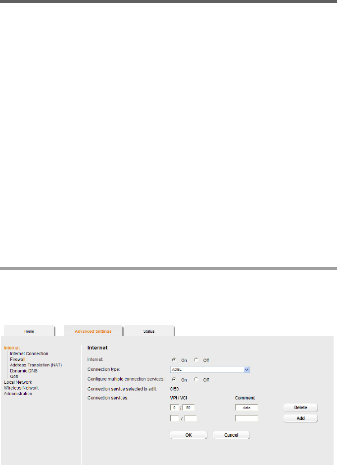
Internet selection
You can activate or deactivate the Internet connection for the router on this screen. You
can choose the connection type and set up and edit a number of connection services.
ìIn the Advanced Settings menu, select: Internet.
ìSelect the appropriate option to activate or deactivate the Internet function of the
router.
Internet Activate/deactivate the Internet connection, set up
additional connection services and edit the virtual
connection parameters (see page 23),
Internet Connection Check and edit the configuration of the Internet connection
(see page 25),
Firewall Protect the network against unauthorised external access
(see page 28),
Address Translation
(NAT)
Provide your own services on the Internet (NAT, see
page 30),
Dynamic DNS Set up dynamic DNS (page 35),
Qos Quality of service: You can define the settings and quality for
data transfer (see page 36)
24
Configuring Advanced Settings
ìChoose the desired Connection type for your Internet connection:
– Choose the ADSL if you are using the integrated ADSL modem of the router.
–Choose Ethernet if you are setting up the connection to the Internet via an Eth-
ernet network connection (e.g. if you are using an external modem with an Eth-
ernet connection).
If you change the connection type, you must also modify your Internet access settings
accordingly (page 25).
ìIf you have selected Ethernet, click OK to save and apply the changes.
ìIf you have selected ADSL, you can now set up multiple connection services.
Configure multiple connection services
Your Internet service provider can permit you to set up a number of Connection serv-
ices. You can set up these services here.
ìSelect the appropriate option to activate or deactivate Configure multiple connec-
tion services.
If you have already configured an Internet connection, this is shown as Connection
service selected to edit. This is then also displayed on other pages of the Internet
menu.
ìMake the following settings:
–Enter the VPI / VCI values for each connection service that you have received from
your Internet service provider.
– Enter a description to identify the respective connection service.
– Click Add to create a new entry.
– Click Delete to delete an entry.
ìClick OK to save and apply the changes.
25
Configuring Advanced Settings
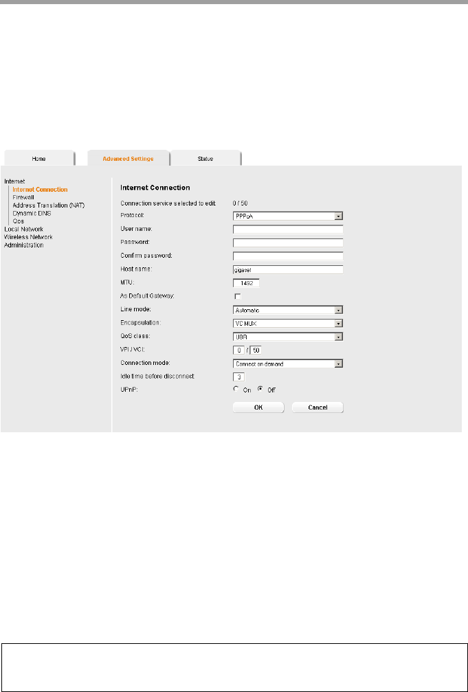
Internet Connection
You can set up or change the configuration of your Internet connection on this screen.
All the settings you make here must coincide with the features your Internet service pro-
vider makes available to you. False information can lead to problems with your Internet
connection.
ìIf you want to configure or modify settings for the Internet connection, select from
the Advanced Settings menu: Internet – Internet Connection.
Connection type ADSL
All settings apply for the displayed connection service that you selected for editing on
the Advanced Settings – Internet (page 23) screen. If you only set up one connection
service, no selection is displayed.
ìEnter the account data you have been given by your service provider: Protocol, User
name, Password.
ìEnter a Host name for your router
ìChoose if your router should be used As Default Gateway for this Internet connec-
tion.
ìApply the default settings for the parameters MTU, Line mode, Encapsulation,
QoS class and VPI / VCI unless your service provider has provided you with other
data.
Note:
Please ensure that you enter all the details from your provider correctly, otherwise the
configuration may fail and you will not be able to connect to the Internet.
26
Configuring Advanced Settings
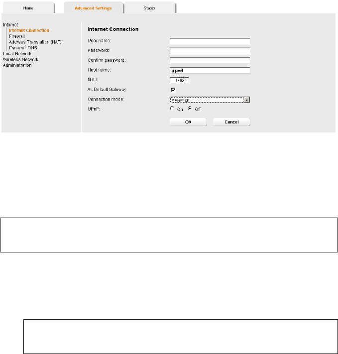
Connection type Ethernet
ìEnter the account data you have been given by your service provider: User name,
Password.
ìEnter a Host name for your router
ìApply the default setting for the parameter MTU, unless your service provider has
provided you with other data.
Setting the Connection mode
ìSpecify how Internet sessions are to be established via Connection mode:
–Select Always on if the connection is to exist at all times when the router is
turned on.
–Select Connect on demand if applications such as an Internet browser or an e-
mail program are to connect to the Internet automatically.
–In the Idle time before disconnect field, enter a period after which the Internet
connection is to end automatically if no data is transmitted (the default setting is
3minutes).
This time setting only applies to the Connect on demand and Connect manu-
ally options.
–Select Connect manually if you always want to establish and end the Internet
connection manually. If you are on a time-based tariff this will save you high con-
nection charges.
ìClick OK to apply the settings.
Note:
Please ensure that you enter all the details from your provider correctly, otherwise the
configuration may fail and you will not be able to connect to the Internet.
Note:
If you are on a time-based tariff, this option can result in high connection
charges.

27
Configuring Advanced Settings
Using UPnP (Universal Plug and Play)
PCs with UPnP (Universal Plug & Play) can offer their own network services and automat-
ically use services offered in the network.
As soon as you have installed UPnP on a PC operating system and activated it on the
router, applications on this PC (e.g. Microsoft Messenger) can communicate via the
Internet without you needing to expressly authorise it. In this case, the router automat-
ically implements Port forwarding, thereby facilitating communication via the Internet.
The task bar on the PC on which UPnP is installed contains an icon for the router. Click
this icon to open the user interface. On Windows XP system, this icon is also shown
under network connections.
ìIn the Advanced Settings menu, select: Internet – Internet Connection.
ìClick UPnP.
ìClick OK to apply the settings.
Note:
The operating system Windows ME, Windows XP or Windows Vista must run on the
PC. Check, if the UPnP function has been installed on the PCs operating system. Maybe
you have to install the UPnP components retroactively. Please consult the documen-
tation of your operating system.
Note:
When the UPnP function is active, system applications can assign and use Ports on a
PC. This poses a security risk.
28
Configuring Advanced Settings
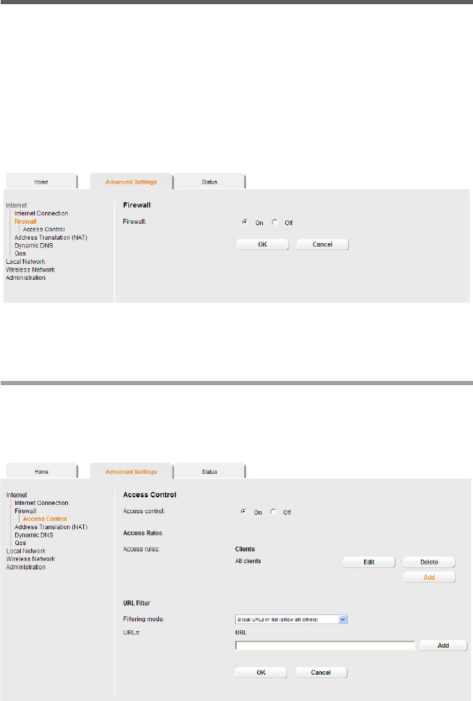
Firewall
The firewall functions of the router Gigaset 504 AGU include various security functions
for the local network.
You can do the following:
uEnable or disable the router firewall.
uBlock access by individual PCs to selected services or Web sites.
The firewall functions for the router are activated and configured in the factory. If you
want to deactivate the firewall, carry out the following steps:
ìIn the Advanced Settings menu, select: Internet – Firewall.
ìClick the required option.
ìClick OK to apply the settings.
Setting up access control to the Internet
The Access Control function allows you to control access to various services for one or
more PCs. You can permit or block access to URLs and services at certain times.
ìIn the Advanced Settings menu, select: Internet – Firewall – Access Control.
29
Configuring Advanced Settings
ìActivate the Access Control function by selecting On.
You have the following setting options for Access Control:
URL Filter
With the URL Filter you can block or allow access to certain Web sites or Internet
domains. When you have entered the relevant URLs, you can create access rules which
use the URL Filter for selected clients in your network.
ìSelect the Filtering mode:
–Allow URLs in list (block all others) or
–Block URLs in list (allow all others)
ìEnter the relevant URL in the field.
ìClick Add to create a new entry.
ìClick Delete to delete an entry.
ìClick OK to apply the settings.
Access Rules
You can limit access to the Internet for all clients, or only for certain clients in the net-
work, thereby allowing or blocking access to services.
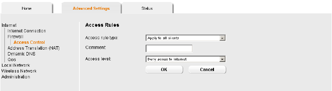
ìClick Add to create an access rule.
ìSelect the Access rule type from the list:
–Apply to all clients: The rule applies to all PCs in the network.
–Specify IP address range: You select the PCs to which the rule is to apply by
entering an IP address range.
–Specify IP address or Specify MAC address: The rule applies to a PC you have
selected via the IP address or MAC address.
ìEnter a name for the access rule in the Comment field.
ìDefine the Access level. Choose one of the following options:
–Deny access to internet
–Allow web browsing
–Allow web browsing with URL filter
If you have set up URL filters on the Access Control screen (page 29), you can
activate them here.

30
Configuring Advanced Settings
–Custom
You can specify your own service filter here.
Specifying an own service filter
The services in the list are blocked for Internet access. The specified service filter applies
to all clients. To create a service filter, proceed as follows:
ìSelect the services that are to be blocked.
– Select predefined services from the Predefined applications list. The most pop-
ular Internet services are offered.
Or
– Specify your own services manually.
Select the Protocol and enter the appropriate port number or port range in the
Port start and Port end fields. To define one single port enter the same number
in both fields.
Entering a Comment that is displayed will help you to identify different services.
Enable the Filter checkbox to use the respective service for the service filter.
ìClick Add to create a new entry with the entered data or for the selected, predefined
application.
ìClick Delete to delete an entry.
ìWhen you have completed all the settings in this screen, click OK to apply them.
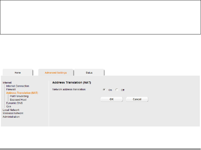
Setting up the NAT function
The router Gigaset 504 AGU comes equipped with the NAT (Network Address Transla-
tion) function. With address mapping, several users in the local network can access the
Internet via one or more public IP addresses. All the local IP addresses are assigned to
the router's public IP address by default.
One of the characteristics of NAT is that data from the Internet is not allowed into the
local network unless it has been explicitly requested by one of the PCs in the network.
Most Internet applications can run behind the NAT firewall without any problems. For
example, if you request Internet pages or send and receive e-mails, the request for data
from the Internet comes from a PC in the local network, and so the router allows the
data through. The router opens precisely one port for the application. A port in this con-
text is an internal PC address, via which the data is exchanged between the Internet and
a client on a PC in the local network. Communicating via a port is subject to the rules of
a particular protocol (TCP or UDP).
If an external application tries to send a call to a PC in the local network, the router will
block it. There is no open port via which the data could enter the local network.
Some applications, such as games on the Internet, require several links, i.e. several ports
so that the players can communicate with each other. In addition, these applications
must also be permitted to send requests from other users on the Internet to users in the
local network. These applications cannot be run if Network Address Translation (NAT)
has been activated.
31
Configuring Advanced Settings
Using port forwarding (the forwarding of requests to particular ports) the router is
forced to send requests from the Internet for a certain service, for example a game, to
the appropriate port(s) on the PC on which the game is running.
When the router is supplied, the NAT function (Network Address Translation) is acti-
vated, i.e. all IP addresses of PCs in the local network are converted to the router's public
IP address when accessing the Internet.
32
Configuring Advanced Settings
You can use the NAT settings to configure the router to carry out the following tasks:
uSet up the router as a virtual server by configuring Port Forwarding (page 32),
uOpen the firewall for a selected PC (page 34).
By default the NAT function is activated. You should only deactivate the NAT function if
you want to configure you own firewall in you local network.
ìIn the Advanced Settings menu, select: Internet – Address Translation (NAT)
ìSelect the required option.
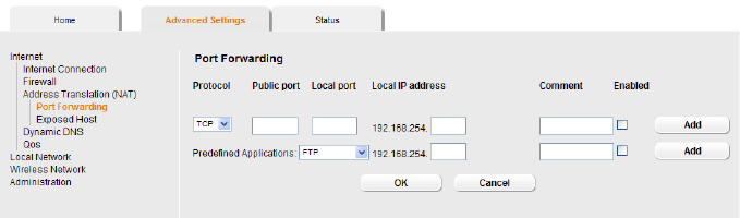
Port Forwarding
If you configure Port Forwarding, the router Gigaset 504 AGU outwardly assumes the
role of the server. It receives requests from remote users under its public IP address and
automatically redirects them to local PCs. The private IP addresses of the servers on the
local network remain protected.
Internet services are addressed via defined port numbers. The router needs a mapping
table of the port numbers to redirect the service requests to the servers that actually
provide the service.
Port Forwarding has been configured for this purpose.
Note:
For the functions described below, the IP addresses of the PCs must remain
unchanged. If the IP addresses of the PCs are assigned via the DHCP server of the
router, you must select Never expires (page 38) as the setting in the Local Network
menu entry for the Lease time or assign static IP addresses for the PCs.
33
Configuring Advanced Settings
ìIn the Advanced Settings menu, select: Internet – Address Translation (NAT) –
Port Forwarding
ìSelect the required application from the Predefined Applications list.
ìSelect the checkbox in the Enabled column to activate the entry.
ìClick the Add button. The data for the required service is entered on the screen.
ìClick the Delete button to delete an entry.
If the application you require is not in the list, you must manually enter the relevant data
on the screen:
ìSelect the protocol for the service you are providing from the Protocol list.
ìUnder Public port, enter the port number(s) of the service you are providing.
You can use
– a single port number,
– several port numbers separated by commas,
– port blocks consisting of two port numbers separated by a dash, or
– any combination of these (for example 80,90-140,180).
ìIn the Local port field, enter the internal port number to which service requests are
to be forwarded.
You can only specify one port number here.
ìEnter the IP address of the PC that provides the service in the Local IP address field.
Example: The Web server has been configured to react to requests on port 8080.
However, the requests from Web sites enter the Web server via port 80 (standard
value). If you add the PC to the forwarding table and define port 80 as the public
port and port 8080 as an internal port, all requests from the Internet are diverted to
the service with the port number 80 on the Web server of the PC you have defined
with port 8080.
ìComment: Enter a description that makes it easy to identify different entries.
ìSelect the checkbox in the Enabled column to activate the entry.
ìClick the Add button to add a new entry.
ìClick the Delete button to delete an entry.
ìClick OK to apply the settings.
34
Configuring Advanced Settings
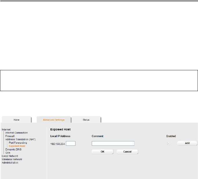
Opening the firewall for a selected PC (Exposed Host)
You can set up a client in your local network to be a so-called "exposed host" (DMZ). Your
device will then forward all incoming data traffic from the Internet to this client. You can
then, for example, operate your own Web server on one of the clients in your local net-
work and make it accessible to Internet users.
As the exposed host, the local client is directly visible to the Internet and therefore par-
ticularly vulnerable to attacks (e.g. hacker attacks). Only activate this function if it is
absolutely necessary (e.g. to operate a Web server) and other functions (e.g. port for-
warding) are not adequate. In this case you should take appropriate measures for the
clients concerned.
ìIn the Advanced Settings menu, select: Internet – Address Translation (NAT) –
Exposed Host
ìEnter the Local IP Address of the PC that is to be enabled as an Exposed Host.
ìEnter a name for the PC in the Comment field.
ìActivate Enabled by ticking the check box.
ìClick the Add button to add the entry to the list.
You can add more than one PC to the list, but you can only activate one of them.
ìClick the Delete button to delete the entry from the list.
ìApply the settings by clicking OK.
Note:
Only one PC per public IP address can be set up as an Exposed Host (see also Port For-
warding on page 32).
35
Configuring Advanced Settings
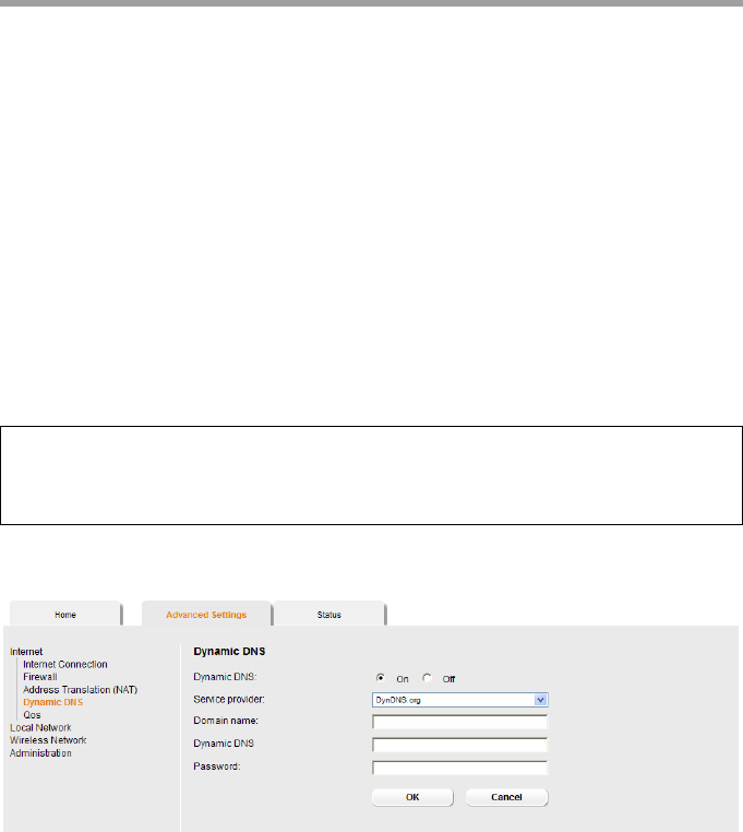
Dynamic DNS
Any service you provide on the Internet can be accessed via a Domain name. Your
router's Public IP address is assigned to this domain name. If your Internet service pro-
vider assigns the IP address for your local network's WAN connection dynamically, the IP
address of the router can change. The assignment to the domain name will no longer
be valid and your service will no longer be available.
In this case you must ensure that the assignment of the IP address to the domain name
is updated regularly. This task is performed by the dynamic DNS service (DynDNS). You
can use the DynDNS service to assign the router Gigaset 504 AGU an individual fixed
domain name on the Internet even if it does not have a static IP address.
Various Internet service providers offer a free DynDNS service.
If you use the service of a DynDNS provider, your service can be reached on the Internet
as a subdomain of one of the DynDNS service domains.
One possible service is DynDNS.org (http://www.DynDNS.org). If you have activated
the device's DynDNS function, it will monitor its public IP address. When this changes,
the device will open a connection to DynDNS.org and update its IP address there.
ìIn the Advanced Settings menu, select: Internet – Dynamic DNS
ìActivate the Dynamic DNS function.
ìSelect a provider from the Service provider list.
ìEnter Domain name, User name and Password. You will have received all the nec-
essary information when you registered with your Service provider.
ìClick OK to apply the settings.
Note:
You must have an account with the service you have chosen (e.g. DynDNS.org) before
you can use the DynDNS function. Follow the instructions on the provider's Web site.
Then enter the user data when configuring the router.
36
Configuring Advanced Settings
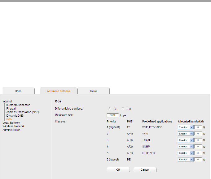
Qos (Quality of Service)
Many communication and multimedia applications require high speed and large band-
widths to transfer data between the local network and the Internet. However, for many
applications there is often only one Internet connection available with limited capacity.
Qos (Quality of Service) divides this capacity between the different applications and
provides undelayed, continuous data transfer where data packets with higher priority
are given transmission preference.
The QoS configuration dialogue enables you to optimise the transmission behaviour for
certain applications. For example IPTV is your favourite application and so you want to
ensure that no other application will disturb the transmission of IPTV data.
ìIn the Advanced Settings menu, select: Internet – Qos.
All settings apply for the displayed connection service which you selected for processing
in the Advanced Settings – Internet screen (page 23).
ìSelect the option Differentiated services, i.e. the prioritisation of certain services
for the data transfer between your network and the Internet.
For each Priority is specified which data packets are to be given priority of transfer. In
addition, PHBs (Per Hop Behaviours) are used to decide whether data packets are to be
forwarded immediately and ahead of all others (EF, Expedited Forwarding), guaranteed
and without data loss (AF, Assured Forwarding), or normally (BE, Best Effort). If your
application already supports QoS, it determines the priority automatically. Your device
recognises this when forwarding. It recognises certain Predefined applications and
assigns each packet the relevant priority. You can also define what proportion of the
bandwidth for your Internet connection is to be made available to a particular class as
Allocated bandwidth.
ìSelect the Allocated bandwidth for Predefined applications.
ìClick OK to save and apply your changes.
37
Configuring Advanced Settings
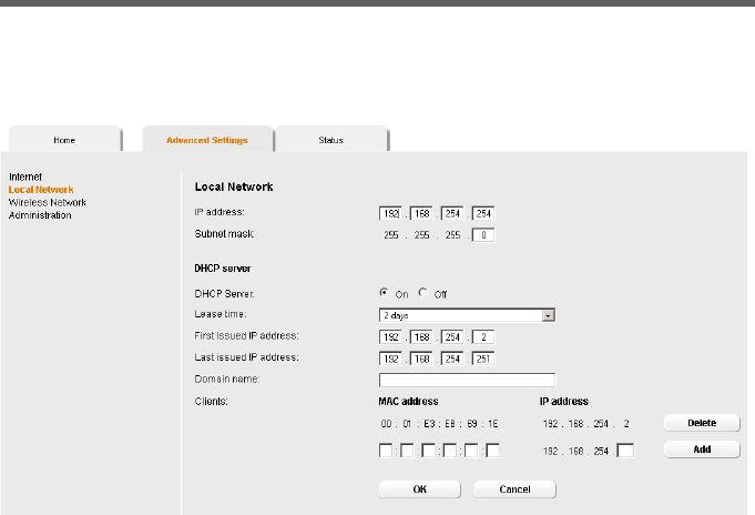
LAN configuration
You can use the LAN configuration to define an IP address for the router Gigaset 504
AGU and configure the DHCP server.
ìIn the Advanced Settings menu, select: Local Network.
Defining the private IP address for the router Gigaset 504 AGU
On this screen you can change the device's IP address. The preset IP address is
192.168.254.254. This is the Private IP address of the router. This is the address under
which the device can be reached in the local network. It can be freely assigned from the
block of available addresses. The IP address under which the router can be reached from
outside is assigned by the Internet service provider. The default Subnet mask for the
local network administered by the router is 255.255.255.0.
ìIf you want to assign a different IP address to the router, enter your chosen IP address
in the boxes next to IP address.
Please make sure to note which subnet mask is set when assigning the IP address.
The preset subnet mask defines that the first three parts of the IP address must be
identical for all network components (including routers).
We recommend that you use an address from a block that is reserved for private use.
This address block is 192.168.1.1 to 192.168.255.254.
ìAdjust the Subnet mask if necessary.
The Subnet mask specifies how many address parts of the IP address must be iden-
tical for all network components (including routers).

38
Configuring Advanced Settings
Configuring the DHCP server
The router has a DHCP server for which the factory setting is active. Consequently, the
IP addresses of the PCs are automatically assigned by the router.
ìTo activate the DHCP server, select On.
ìIf the DHCP server is active, you can define a Lease time. The least time indicates
how long the client may use the allocated IP configuration.
ìDefine the range of IP addresses the router should use to automatically assign IP
addresses to the PCs. Define the First issued IP address and the Last issued IP
address.
ìYou can define the name of a domain (Windows workgroup) in the Domain name
field.
ìApply the settings by clicking OK.
Assigning static IP addresses to individual PCs
Even if you have activated the DHCP server, you can still assign a static IP address to indi-
vidual PCs (e.g. when setting up these PCs for NAT functions).
ìEnter the MAC address of the PC to which you want to assign a static IP address.
ìEnter the IP address you wish to assign to the PC.
ìClick Add to add the entry to the list.
ìClick Delete to delete the entry from the list.
ìApply the settings by clicking OK.
Notes:
New settings can only be made after the router has been rebooted. If necessary,
reconfigure the IP address on your PC (including one that is statically assigned) so that
it matches the new configuration.
Note:
uIf the DHCP server for the router is activated, you can configure the network set-
ting on the PC so that the option Obtain an IP address automatically is set up.
For further information, refer to the section entitled "Configuring the local area
network" on the CD-ROM.
uIf you deactivate the DHCP server, you will have to assign a static IP address for the
PCs that use the network settings.
Note:
If you select Never expires, the IP addresses are never changed. Activate this
option if you want to make NAT or firewall settings using the IP addresses of the
PCs; otherwise you have to assign static IP addresses to these PCs.
39
Configuring Advanced Settings
Configuring wireless connections
The WLAN function of your router Gigaset 504 AGU is deactivated on delivery. You can
activate it on this page.
If you have implemented wireless PC communication via the router, you should improve
the security settings of your wireless network via the Advanced Settings – Wireless
Network menu. You can carry out the following functions:
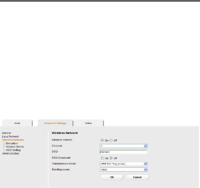
ìIn the Advanced Settings menu, select: Wireless Network.
ìSelect On for the Wireless Network.
Devices can only log in wirelessly if the WLAN module of the router is activated.
You can now make the settings for the wireless network.
Channel
All clients in the network use the set radio channel for wireless data transfer. You can
choose between various channels, depending on your current location.
ìSelect Automatic so that the best channel for transmitting the data is used automat-
ically.
Wireless Network Activate the wireless module of the router and specify basic
settings for your wireless network, for example SSID,
Transmission mode or Sending power.
Encryption Set up Encryption for wireless transmissions (page 41).
Allowed Clients Restrict access to the LAN of the router (page 45).
WDS Setting Activate the repeater function (Wireless Distribution
System, WDS) and define repeaters to increase the range of
your WLAN (see page 46).

40
Configuring Advanced Settings
SSID
For the wireless network components to be able to communicate with one another, you
must use the same SSID (Service Set Identifier).
The default SSID for the router is AIShamil. For security reasons you should change this
SSID.
ìEnter a character string of your choice. The SSID is case-sensitive. It can contain up
to 32 characters. Use a combination of letters, digits and special characters.
SSID broadcast
If this option is enabled, the router will send the SSID in all data transfers and the SSID
of the router will be displayed on PCs that have a wireless network adapter. In this case,
hackers could use the SSID to detect your network.
If SSID broadcast is deactivated, the SSID of the router will not be displayed. This
increases protection against unauthorised access to your wireless network. Make a note
of the SSID. You will need it to log on to the PC.
ìSelect Off to deactivate SSID broadcast.
To protect your wireless network, you should also enable encryption of data transmis-
sions (page 41).
Transmission mode
The IEEE 802.11g standard permits data transfer up to 54 Mbit/s, and the IEEE 802.11b
standard up to 11 Mbit/s. Choose IEEE 802.11g only to ensure the best possible data
transfer rates in your network. To operate clients with older wireless network adapters
in your network, select IEEE 802.11b/g (mixed).
ìSelect the required transmission mode for your wireless network.
Sending power
ìSelect the required sending power for your device.
It is recommended that you select a sending power with a range to suit the spatial
environment of your local network. A much greater range makes it easier to eaves-
drop on your wireless data transfer.
ìClick OK to apply the settings.
Note:
The connection to the wireless network adapters will be interrupted until you have
entered the new SSID in them as well.
41
Configuring Advanced Settings
Setting encryption
If you are sending data over radio channels, we recommend that you activate encryp-
tion (WEP or WPA) on the components in the wireless network. WPA offers greater secu-
rity than WEP. You should therefore select WPA encryption if it is supported by all com-
ponents in your wireless network.
WPA-PSK is a more efficient method for protecting wireless networks. Dynamic keys,
based on TKIP (Temporal Key Integration Protocol) offer increased security. The new
WPA2-PSK standard is based on AES.
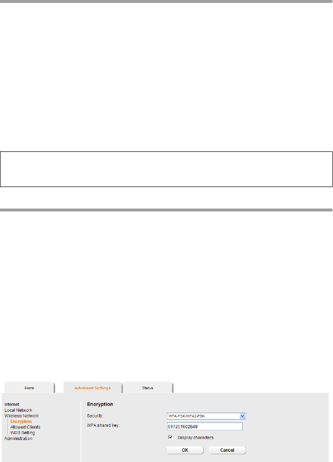
ìIn the Advanced Settings menu select: Wireless Network – Encryption
The following security mechanisms are currently available:
uWPA2-PSK and WPA2-PSK/WPA-PSK (page 41)
uWEP encryption (Wired Equivalent Privacy, page 42)
WPA2-PSK and WPA-PSK/WPA2-PSK
WPA with pre-shared key (WPA-PSK)
WPA-PSK is a special WPA mode for private users and users in small companies without
their own authentication server. After a certain period of time (Rekey interval), encryp-
tion keys are automatically generated with the pre-shared key, automatically changed
("rekeying") and authenticated between the devices.
The standard of encryption available to you depends on the components in the wireless
network. Every PC (network adapter) that requires access to a WPA-protected wireless
network must also support WPA. To find out whether and how you can use WPA on your
PC, read your network adapter's user guide. If all components support WPA2, select
WPA2-PSK. If you are using network adapters that only support WPA, select WPA-PSK/
WPA2-PSK. Your device then automatically defines the best possible way to protect your
data for each client. The entries described below are identical for both options.
ìSelect the required option in the Security field.
ìEnter a key in the WPA shared key field (up to 32 characters) and confirm it by
entering it again. Use a combination of letters, digits and special characters.
Note:
If you want to use the repeater function of your router (page 46) you can only use WEP
encryption.
42
Configuring Advanced Settings
ìIf you select the Display characters option, the WPA shared key will be displayed
in readable characters.
ìClick OK to apply the settings.
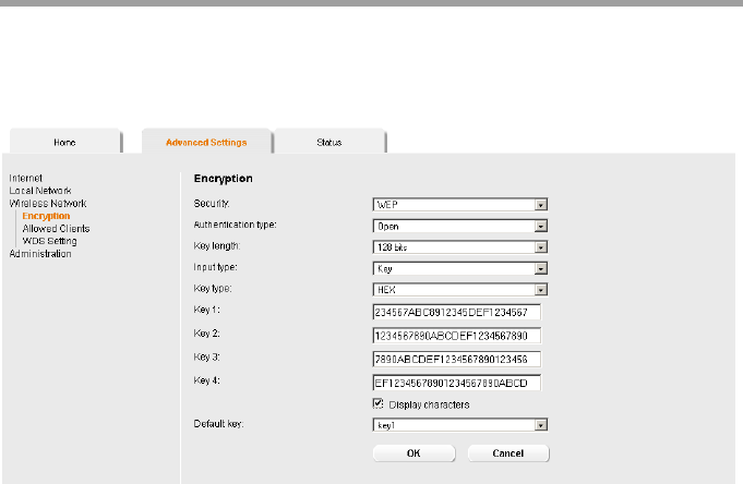
WEP encryption
If WPA is not supported by all components in your wireless network, we recommend
that you activate WEP Encryption on the components.
ìChoose the WEP option in the Security field.
ìSelect the Authentication type:
–Select Shared to require that each client log in to the network with a specified
key.
–Select Open to permit data transfer within the wireless network without the need
to enter a key.
You can choose either the standard 64-bit key or the more robust 128-bit key. The keys
are generated in hexadecimal or in ASCII format. You must use the same keys for encryp-
tion and decryption for the router and all your wireless network adapters.
ìSelect the Key length: 64 bits or 128 bits.
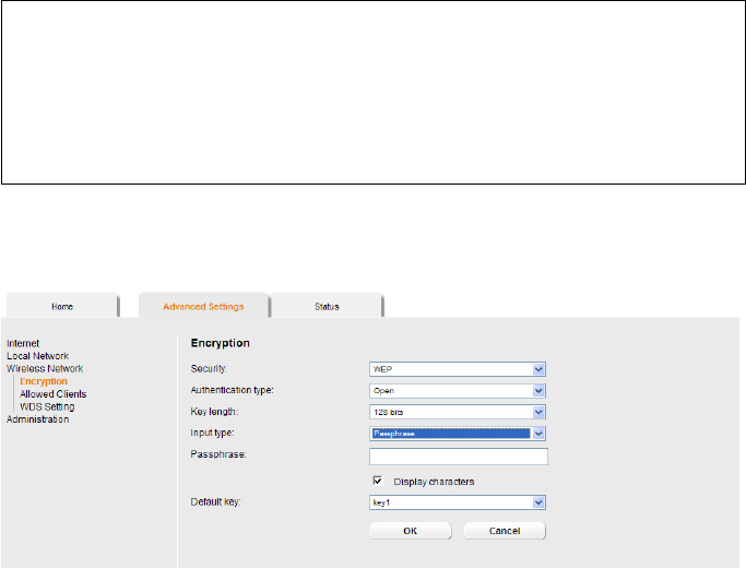
ìSelect the Input type, i.e. whether the key is to be entered manually or generated
automatically by means of a Passphrase.
43
Configuring Advanced Settings
Manual key entry
ìSelect the Key type, Hex or ASCII.
If you select Hex as the key type, you can use the characters 0 to 9 and A to F.
– With a 64-bit encryption depth, the key is 10 characters long.
An example of a valid key: 1234567ABC
– With a 128-bit encryption depth, the key is 26 characters long.
An example of a valid key: 234567ABC8912345DEF1234567
If you select ASCII as the key type, you can use the characters 0 to 9, A to Z, a to z
plus the special characters in the ASCII character set.
– With a 64-bit encryption depth, the key is 5 characters long.
An example of a valid key: GIGA1
– With a 128-bit encryption depth, the key is 13 characters long.
An example of a valid key: GIGASET_504AG
ìEnter up to four keys in fields Key 1 to Key 4.
ìIf you select the Display characters option, the keys will be displayed in readable
characters.
ìSelect one of the four keys as the Default key.
ìClick OK to apply the settings.
Generating a key by means of a Passphrase
ìEnter a Passphrase (up to 32 characters) and confirm it by entering it again. The key
is generated automatically.
Note:
uIt is very important that you make a note of the key(s) that have been entered.
You will need this information to configure the wireless network adapters prop-
erly.
uWhen you have concluded the configuration, you must change the WEP encryp-
tion in the wireless network adapters for the connected PCs in the same way as
they will not otherwise be given access to the wireless network of the router.
44
Configuring Advanced Settings
ìIf you select the Display characters option, the Passphrase will be displayed in
readable characters.
ìClick OK to apply the settings.
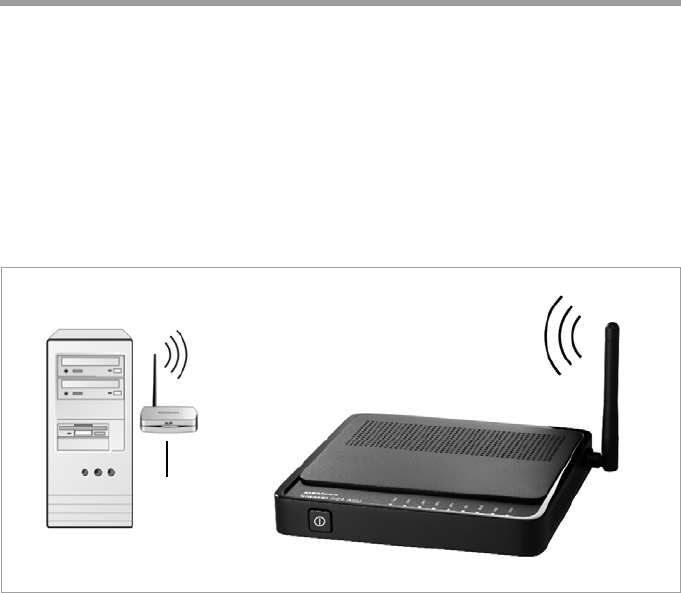
Connecting PCs wirelessly
A wireless connection is made using a wireless network adapter that must be installed
in your PC. This can be an 802.11g or 802.11b-compatible wireless network adapter.
A wireless network is defined by assigning an identical SSID to all the devices.
ìYou should therefore enter the SSID for the router in your network adapter configu-
ration: The default SSID is AlShamil.
ìChoose the used encryption method in the configuration settings of your network
adapter and enter the correct key.
If the correct SSID and encryption key has been entered in your PC's wireless network
adapter, the wireless link will be established automatically.
WLAN
adapter
45
Configuring Advanced Settings
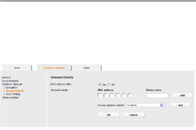
Permitted clients
On this screen you can specify the PCs that are to have wireless access to the router
Gigaset 504 AGU and hence to your LAN and WLAN.
The default setting for access control is deactivated. This means that all PCs that use
the correct SSID can be logged in.
Access control is based on the MAC addresss of the PC network adapters.
ìIn the In the Advanced Settings menu select: Wireless Network – Allowed Cli-
ents.
ìActivate access control by selecting On in the MAC address filter field.
Entering PCs manually:
ìEnter the MAC Address and Device name of the required PCs in the appropriate
fields.
ìClick Add to add the entry to the list.
ìClick Delete to delete the entry from the list.
Note: Only following deletion is the entry transferred to the list of known MAC
addresses.
ìApply the settings by clicking OK.
Selecting from the list of logged-in PCs
ìSelect the required PC from the Known wireless clients list. All PCs that were
already entered manually on the router with the MAC address are displayed.
ìClick Add to add the selected PC to the list.
ìClick OK to apply the settings.

46
Configuring Advanced Settings
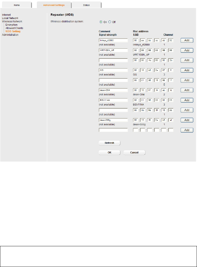
Repeater function (WDS)
WDS (Wireless Distribution System) allows you to extend the range of your wireless net-
work using a repeater. A repeater located at the outer range of a wireless network
ensures that data is forwarded between WLAN clients in this wireless network and cli-
ents within its own wireless range. Repeaters and access points thereby form a common
wireless network within which all clients can be moved about freely. Clients automati-
cally set up a connection to the next access point / repeater (roaming). For security pur-
poses you must determine which access points / repeaters are to form a common wire-
less network.
If you want to use a repeater in your wireless network you must activate the Wireless
Distribution System (WDS) function.
ìIn the In the Advanced Settings menu select: Wireless Network – WDS Setting
ìTo activate WDS select the On option next to Wireless distribution system.
The environment is scanned for wireless networks in rage. If the search has been com-
pleted successfully the networks are displayed.
Note:
If you activate MAC access control, you must at least add the PC on which you are con-
figuring the router to the list. Otherwise, you will have no access to the user interface
and will receive an appropriate error message.
If you have inadvertently denied all PCs access to the router, you have two options:
uYou can completely reset the router (page 10).
uYou can connect a PC to the router using one of the LAN connections. As MAC
access control only affects PCs that are connected wirelessly, you can use this PC
to change the configuration.
Note:
WDS can only be used with WEP encryption or without encryption. If you use WPA-PSK
encryption (default) you have to change the encryption of your wireless network. For
information refer to the section "Setting encryption" on page 41.
47
Configuring Advanced Settings
All repeaters/access points in range are displayed with the following information:
–SSID
–Mac address
– Channel
The Signal strength of the connection to the repeater, if one exists, is shown as a per-
centage. You can use this data to determine the best possible location for your repeater.
You can register a maximum of three repeaters to extend your WLAN.
You can enter additional repeaters manually.
ìClick the Add button to register a repeater in your wireless network.
ìClick the Delete button to remove a repeater from your wireless network.
ìClick Refresh to update the display.
ìClick OK to apply the settings.
Note:
The registered but currently unavailable repeaters are shown only by their MAC
addresses.

48
Configuring Advanced Settings
Note:
uWDS can only be used with WEP encryption or without encryption. You may have
to change the encryption of your wireless network, if applicable.
uThe encryption settings on the repeater have to correspond to the settings on your
router.
uThe router and the repeaters must use the same channel.
Further information can be found in the user manual for the repeater.
49
Administration
Administration
The user interface of the router Gigaset 504 AGU includes several helpful functions for
administration.
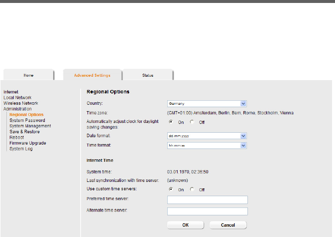
Regional Options
For operating your router Gigaset 504 AGU, you can select the location, time zone and
format for entering the time and date, and you can also configure a time server for the
Internet time (system time).
ìIn the Advanced Settings menu, select: Administration – Regional Options.
ìSelect the country you are currently in from the list.
You can set the time so that it automatically switches to summer time or the Time zone,
as required.
ìSelect the required option or choose the Time zone for your location.
ìSelect the required format for entering the date and time from the Date format and
Time format lists.
Regional Options Enables regional settings (page 49).
System Password Changes the system password (page 50).
System Management Configures system management (page 51).
Save & Restore Backs up and, if necessary, restores configuration data
(page 52) or reset the router to the factory settings
(page 53).
Reboot Reboots the device (page 53).
Firmware Upgrade Updates firmware (page 54).
System Log Configures settings for the system log (page 55).
50
Administration
Internet Time
The System time of the device is automatically synchronised with the time server on
the Internet. The time of the Last synchronization with time server is displayed for
your information.
ìIf you would like to use your own time server, activate the On option next to the Use
custom time servers field.
ìEnter the Internet address of the time server in the Preferred time server or Alter-
nate time server fields.
ìClick OK to apply the settings.
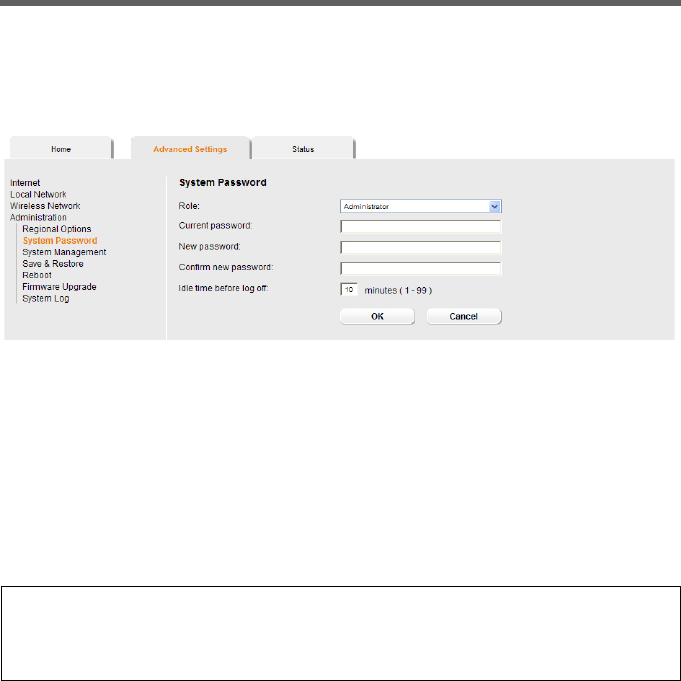
System Password
You can assign a System Password to the user interface of the router Gigaset 504 AGU
and specify the period after which a session is to be automatically ended if no further
entry is made.
ìIn the Advanced Settings menu, select: Administration – System Password.
After installation, the user interface of the router is protected by the System Password
admin. To prevent unauthorised changes being made to the configuration, you should
set a new System Password from time to time.
ìEnter the old System Password in the Current password field.
ìEnter a new System Password in the New password field and repeat it in the
Confirm new password field.
The System Password may contain up to 20 characters. The System Password is case
sensitive. Avoid proper names and all too obvious words. Use a combination of letters,
digits and special characters.
Note
If you forget your System Password, you have to reset the router Gigaset 504 AGU
(page 10). This returns all your settings to the factory configuration. This means the
system password is changed back to admin.
51
Administration
Idle time before log off:
ìEnter the number of minutes after which the configuration program is to be ended
if no further entry is made. The default is 10 minutes. If you enter 0, the program
will never be ended automatically.
ìClick OK to apply the settings.
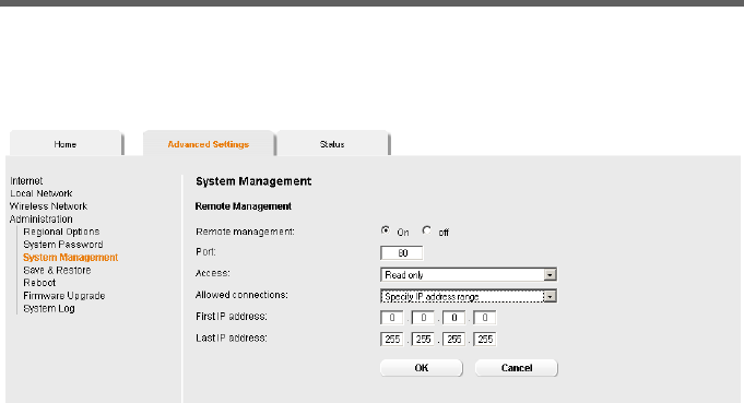
System management
Your router Gigaset 504 AGU offers you the option of using remote management in
addition to the configuration program that you access via a PC in your local network.
ìIn the Advanced Settings menu, select: Administration – System Management.
Remote Management enables a PC that is not in your local network to be used to con-
figure the router via a standard Web browser. You can activate Remote Management for
one particular or for any PC.
For security reasons, this function is only available if you have previously changed the
system password for your device (see page 50).
You can start remote management by entering the public IP address in your Internet
browser. As Internet providers often change this each time you dial in, it is also worth
using dynamic DNS (see page 35).
ìClick the option On, to activate Remote Management.
ìYou can change the Port via which you can access the configuration program from
the Internet, for example in order to mask and protect the configuration program
against unauthorised access.
ìAccess: You can select Read only if you only wish to activate remote management
for reading or you can select Full control if you wish to activate it for reading and
writing.
ìAllowed connections: You can activate this function for
– One particular PC (Specify IP address),
– An range of IP addresses (Specify IP address range) or
–Any PC (Allow all clients).
52
Administration
– Select the required option from the list.
– For the option Specify IP address, enter the IP address of the client; for Specify
IP address range, enter the first and last IP address in the range you want to per-
mit.
ìClick OK to accept the settings.
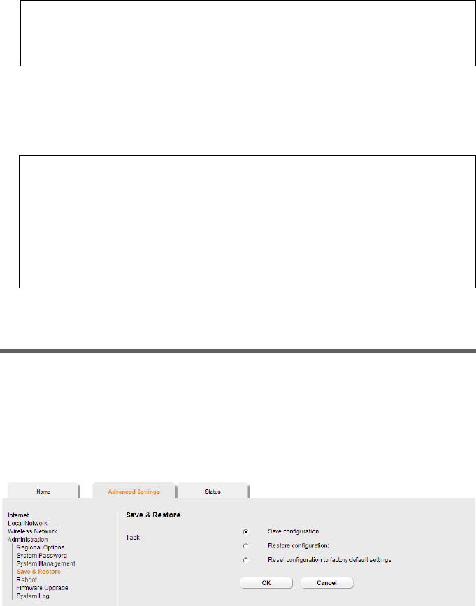
Backing up and restoring a configuration
When the router Gigaset 504 AGU has been configured, it is recommended that you
back up the settings. This means you can restore the settings at any time if they are acci-
dentally deleted or overwritten.
You can also reset the configuration to the factory settings. You should always do this
before handing the device to an external person.
ìIn the Advanced Settings menu, select: Administration – Save & Restore.
Please remember:
If you permit several PCs then anyone who finds out your password can access this
user interface and therefore also your network! If it is needed, then you should
only activate this option for a short time.
Please remember:
uThe Internet provider may assign the IP address to the PC dynamically. This may
change the IP address. Make sure that the PC that is to access the router from
the Internet always has the same IP address.
uFor access to the configuration environment via Remote Management, you
must enter the address of the router Gigaset 504 AGU to be managed in the
browser using the following format: http://X.X.X.X:8080
(x.x.x.x represents the public IP address of the router).

53
Administration
Backing up configuration data
ìFor Task, activate the Save configuration option.
ìClick OK.
You can then set the location in which the backup file is to be saved in a file selection
window.
ìSelect a local directory on your PC where you want to save the configuration file and
enter a file name.
ìClick Save.
The current configuration data is now saved in the specified file.
Restoring the saved data
ìFor Task, activate the Restore configuration option.
ìEnter the path of the backup file that you want to use to restore the configuration
or choose the file in the file system via the Browse button.
A window will appear prompting you to confirm the procedure.
ìClick OK. The configuration will now be updated.
Restoring factory settings
You can reset the router Gigaset 504 AGU to the factory settings. You should do this
before making the device available to others or exchanging it through the dealer. Oth-
erwise unauthorised persons may use the Internet access data at your expense.
ìSelect Reset configuration to factory default settings and click OK.
A window will appear prompting you to confirm the procedure.
Reboot
If the router Gigaset 504 AGU is not operating properly, you can reboot it. It should then
be ready for use again.
ìIn the Advanced Settings menu, select: Administration – Reboot
ìClick OK to reboot the device.
A window will appear prompting you to confirm the procedure.
Note:
If the router is not operating properly, you can reboot it. It should then be ready for
use again (page 10).
Please remember that when the device is fully reset, all the configuration settings are
returned to the factory settings. This means that you will have to completely reconfig-
ure the router.
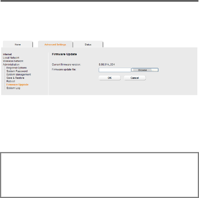
54
Administration
Updating firmware
If Gigaset Communications GmbH or your Internet service provider releases a new ver-
sion of the firmware, you can update the firmware of the router Gigaset 504 AGU. First
download the firmware from the Internet onto your PC.
ìIn the Advanced Settings menu, select: Administration – Firmware Upgrade.
The firmware version that is currently installed on the device is displayed in the Current
firmware version line.
ìEnd all network activities in the local network.
ìIn the Firmware update file field, enter the file with the new firmware that you
have downloaded from the Internet or click Browse to search for the file in your PC's
file system.
ìClick OK. The firmware will now be updated.
After a successful update, the device is automatically rebooted. All LEDs go out. The
login screen is displayed again.
To see whether the upgrade procedure was successfully completed, check the current
software version displayed in the overview of the Status menu (page 56).
Warning:
Do not turn off the router during the updating procedure and do not interrupt the
power supply. Turning off the device can make it unusable. The update can take sev-
eral minutes.
Gigaset Communications GmbH accepts no liability for damage that occurs through
improper use.
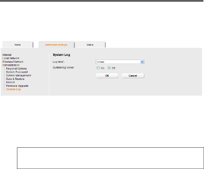
55
Administration
System Log
The System Log is displayed in the Status – Device menu. It contains important infor-
mation about how the device functions and possible problems. This information can
also be automatically transferred to a system log server.
ìIn the Advanced Settings menu, select: Administration – System Log.
ìLog level : Specify how much information is to be contained in the system log. You
can choose between four levels:
–Critical: Log file of the most important information for possible device function-
ality problems.
–Warning and Informational are intermediate levels.
–Debugging: Complete and detailed information on all device functions
ìSystem log server
– Activate this function if the device system log is to be automatically transferred
to a system log server in the local network.
–Server address
Enter the IP address for the system log server.
–Server port
Enter the port of the system log server that is to be used to transfer the system
log.
ìClick OK to save and apply the changes.
Please remember:
Setting the log level Debugging can generate enormous load on the system
and thus impair the data throughput of the device.

56
Status information
Status information
Information about configuration and the status of the router Gigaset 504 AGU is dis-
played in the Status menu of the router. On the first screen you will find an overview of
the status of the Internet connection, the local and wireless network, the USB interface
and the device.
Detailed information is available on the following status screens:
uSecurity
uInternet
uLocal network
uWireless network
uDevice
To display a status screen:
ìSelect Status in the start screen.
ìSelect the entry with the information you require.
Overview
On the first screen you will find an overview of the current operating status and the
most important device data.
Internet
uConnection status
The status of the Internet connection and, if connected, the duration of the connec-
tion.
uIP address
Public IP address of the device.
Local network
uIP address
Local IP address of the device.
uDHCP server
Status of the DHCP server of the device and, if activated, the number of clients in the
network that have been assigned an IP address.
Wireless network
uStatus
Status of the wireless network connection of the device and, if activated, the
number of clients in the wireless network connected to the device.
uSSID
Wireless network ID.

57
Status information
Device
uSystem time
System time of the device.
uFirmware version
Firmware version currently installed on the device.
ìClick Refresh to refresh this screen and update the displayed data.
Security
You will find information about possible security risks for the device and the network on
the Security screen in the Status menu.
In the Status menu, select Security:
uSystem password not changed
The configuration program of the device is not sufficiently protected against unau-
thorised access because you have not changed the system password since setting up
the device. Information on how to avoid this security risk is given in the section "Sys-
tem Password" on page 50.
uIdentification of your wireless network visible or not changed
Unauthorised users can also find the wireless network easily as you have not
changed the ID of the wireless network (SSID) since setup and have not deactivated
SSID broadcasting. Information on how to avoid this security risk is given in the sec-
tion "Configuring wireless connections" on page 39.
uEncryption for your wireless network not activated
None of the data in the wireless network is encrypted during transfer and can there-
fore easily be intercepted. Unauthorised users will also have easy access to your net-
work, your PCs and your Internet connection. Information on how to avoid this secu-
rity risk is given in the section "Setting encryption" on page 41.
uAccess to your wireless network not restricted to allowed clients
Users can access the wireless network from any PC. Information on how to avoid this
security risk is given in the section "Permitted clients" on page 45.
uFirewall for your Internet connection turned off
The network is not protected against hackers who gain unauthorised access via the
Internet. Information on how to avoid this security risk is given in the section "Fire-
wall" on page 28.
uAddress translation for your Internet connection turned off
The clients in the network are not protected against unauthorised access via the
Internet. Information on how to avoid this security risk is given in the section "Set-
ting up the NAT function" on page 30.
uOne or more of your local clients directly exposed to the Internet
At least one client in the network is directly visible on the Internet as an exposed host
and is therefore particularly exposed to the risk (e.g. through hacker attacks). Only
activate this function if it is absolutely necessary (e.g. to operate a Web server) and

58
Status information
other functions (e.g. Port forwarding) are not suitable. In this case, you should take
the appropriate measures on the clients concerned. Information on how to avoid
this security risk is given in the section "Opening the firewall for a selected PC
(Exposed Host)" on page 34.
uRemote management enabled
All users, including unauthorised ones, who find out the system password for the
device can access the device’s configuration program via the Internet. The section
"System management" on page 51 explains how you can avoid this security risk.
ìClick Refresh to refresh the screen and the displayed data.
Internet
You will find information about the status of the Internet connection of the device on
the Internet screen in the Status menu.
In the Status menu, select Internet:
uConnection service
You can select the Connection service, for which the following information is to be
displayed.
This information is not displayed if you only set up one connection service.
uConnection status
Status of the Internet connection and, if connected, the duration of the connection.
If you have set Connect on demand or Connect manually as the connection mode
(page 25), you can Connect or Disconnect the connection to the Internet manually
here.
uConnection mode
Connection mode set for connecting to the Internet.
uIP address
Current public IP address of the device.
uMAC address
Public MAC address of the device.
uDefault gateway
IP address of the assigned default gateway.
ADSL Line
uStatus
Status of the cable connection from your device to your DSL port.
uLine mode
Line mode used by your DSL port.
uMaximum line rate
Maximum possible data transfer rate of your DSL port for incoming and outgoing
data traffic.

59
Status information
uNoise margin
Maximum signal-to-noise ratio of your DSL port for incoming and outgoing data
traffic.
uLine attenuation
Line attenuation of your DSL port for incoming and outgoing data traffic.
uOutput power
Output power of your DSL port for incoming and outgoing data traffic.
Address Translation (NAT)
uStatus
Status of the NAT (Network Address Translation) for the Internet connection.
uNAT table
Current number of entries in the NAT table.
ìClick Empty to delete all the current entries in the NAT table.
Dynamic DNS
uStatus
Status of the configuration for dynamic DNS. If dynamic DNS is set up, the name of
the provider is shown.
uDomain name
Shows the domain name range for dynamic DNS.
ìClick Refresh to refresh this screen and update the displayed data.
Local Network
You will find information about the local network settings on the Local Network screen
in the Status menu.
In the Status menu, select Local network:
uIP address
Local IP address of the device.
uSubnet mask
Subnet mask used in the local network.
uMAC address
Local MAC address of the device for wired data transfer.
DHCP server
uStatus
Status of the DHCP server of the device for automatic assignment of IP addresses to
clients in the local network.

60
Status information
uDHCP clients
Clients in the network that have been assigned an IP address. The Host name and
the MAC address are listed to identify each client. Information is also provided
about the IP address assigned to each client and about the Lease time for the IP
address, i.e. the length of time before the current IP address becomes invalid and the
client is assigned a new address by the DHCP server.
ìClick Refresh to refresh this screen and update the displayed data.
Wireless Network
You will find information about the wireless network settings on the Wireless network
screen in the Status menu.
In the Status menu, select Wireless network:
uStatus
Status of the connection between the device and the wireless network.
uSSID
Wireless network ID.
uChannel
Radio channel that is currently being used for data transfer in the wireless network.
uMAC address
Local MAC address of the device for wireless data transfer.
uWireless clients
Clients in the wireless network that are currently connected to the device. The Host
name, MAC address and IP address are specified for identifying each client. You
will also see information about the Uptime to date of the current connection for
each client in the wireless network.
Repeater (WDS)
uStatus
Status of the WDS (Wireless Distribution System) in the wireless network for increas-
ing the range (Enabled or Disabled).
uWDS links
Current number of connections to other access points or repeaters in the wireless
network.
ìClick Refresh to refresh this screen and update the displayed data.

61
Status information
Device
You will find the most important device data on the Device screen in the Status menu.
In the Status menu, select Device:
uSystem uptime
Device's operating time since the last time the system was started.
uSystem time
System time for your device.
uFirmware version
Firmware version currently installed on your device.
uBootcode version
Version of the bootcode currently installed on your device.
uADSL driver version
Version of the ADSL driver currently installed on the device.
uWireless driver version
Version of the WLAN driver currently installed on the device.
uUser interface version
Version of the user interface currently installed on the device.
uHardware version
Hardware version of the device.
uSerial number
Serial number of the device.
System Log
The system log contains important information about how the device functions and
possible problems. You can adapt the scope of the system log to suit your requirements
(see "System Log" on page 55).
ìClick Refresh to refresh this screen and update the displayed data.

62
Appendix
Appendix
Troubleshooting
This section describes common problems and their solution. Any problems can be iden-
tified from the different LED displays. If you cannot solve the connection problem after
checking the LED displays, consult of the following table. Further information is availa-
ble on the Internet at
http://www.gigaset.com/customercare.
Make sure the firmware on your device is up-to-date. The latest version can be found on
the Internet on the product page
www.gigaset.com/gigaset504 or www.gigaset.com/gigaset501
Symptom Possible cause and solutions
Power LED does not light
up.
No power supply.
ìCheck whether the mains adapter is connected to
the router and a power outlet.
ìCheck whether the power outlet and the mains
adapter are working properly. If the mains adapter
is not working properly, contact our customer serv-
ice unit (see Quick Start Guide).
ìIf your router has an On button: Check whether the
device is plugged in.
ADSL LED flashes. ìWait until the integrated DSL modem has com-
pleted its synchronisation. This procedure can take
up to 10 minutes.
ìThe LED will also flash (at regular intervals) if no
DSL cable is attached.
The ADSL LED does not light
up after synchronisation.
ìCheck the DSL cable. Check that the DSL cable is
properly connected to the DSL port and the splitter.

63
Appendix
The LAN LED on a con-
nected device does not light
up.
No LAN connection
ìMake sure the connected device is turned on.
ìCheck whether the Ethernet cable is plugged in.
ìCheck that you are using the right cable type
(CAT5) and that the cable is not too long (<100m).
ìCheck that the network card on the connected
device and the cables are not defective. If neces-
sary, replace a defective network card or cable.
ìUse the Windows device manager (My Computer –
Properties) to check whether the network card is
functioning. If you see a red cross or a question
mark, the driver may not have been installed or
there is a resource conflict. Follow the Windows
instructions to remedy the problem.
You cannot connect to the
Internet.
ìCheck whether the Connect manually option is
activated. If it is, connections cannot be opened
automatically.
ìSelect Connect on demand or Always on. If you
are on a time-based tariff, this option can result in
high connection charges (see page 26).
ìThe connection may have been terminated manu-
ally with the Connect on demand option selected.
– Restore the connection again manually using the
Connect button.
Or
– Restart the router.
In both cases, the Connect on demand setting will
be active again.
ìCheck whether the data entered for your Internet
connection matches what your Internet service
provider has specified.
You cannot open a connec-
tion to the router from a
wireless device.
uThe wireless network adapter is not using the cor-
rect SSID.
ìChange the SSID on the network adapter.
Symptom Possible cause and solutions

64
Appendix
You cannot open a connec-
tion to the router from a
wireless device.
uEither encryption has been activated on the router
but not on the wireless network adapter, or an
incorrect key is in use.
ìActivate the required encryption on the network
adapter with the correct key.
If you do not know the key, repeat key entry
(page 41) via a PC connected via cable to the router
and enter the new key on the network adapter.
Alternatively, you can reset the router (page 10)
and then reconfigure encryption.
Warning: Please bear in mind that this will reset
the entire configuration to the factory settings.
uMAC access control is activated, but the PC is not
included in the MAC address list.
ìEnter the PC in the MAC address list.
The router or other PCs can-
not be reached by a PC in the
connected LAN using a
ping command.
ìMake sure that TCP/IP has been installed and con-
figured on all the PCs in the local network.
ìCheck that the IP addresses have been correctly
configured. In most cases you can use the DHCP
function of the router to assign dynamic addresses
to the PCs in the LAN. In this case, you have to con-
figure the TCP/IP settings of all the PCs so that they
obtain the IP address automatically.
If you configure IP addresses in the LAN manually,
remember to use the same subnet mask for all PCs
in the LAN. This means that the masked part of the
IP address on each PC and on the router has to be
identical.
You cannot open a connec-
tion to the configuration
environment of the router.
ìUse the ping command to check whether you can
establish a network connection to the router.
ìCheck the network cable between the PC you want
to use to administer the device and the router.
ìIf the PC you want to use for administering the
device is in the router's local network, make sure
that you are using the correct IP address range
(see above).
ìIf the PC you want to use for administering the
device is not in the router's local area network, this
PC must be authorised for remote management.
Symptom Possible cause and solutions

65
Appendix
You have forgotten or lost
the password .
ìReset the router (page 10).
Warning: Please bear in mind that this will return all
the configuration settings to the factory settings.
You cannot access a
resource (drive or printer)
on a different PC.
ìMake sure that TCP/IP has been installed and con-
figured on all the PCs in the local network and that
the PCs all belong to the same workgroup.
ìCheck whether the resource has been released on
the PC in question and whether you have the nec-
essary access rights.
ìPrinting: Check whether the printer has been set up
as a network printer.
Operating information:
uLAN ports
The LAN ports may only be used for in-house networks. The ports are destroyed
externally if there is a power surge.
Symptom Possible cause and solutions
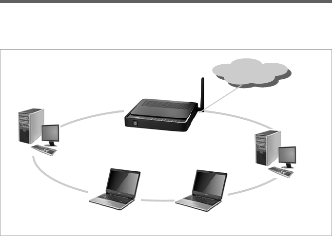
66
Appendix
Local area networks with Gigaset products
You can use the router Gigaset 504 AGU to set up a local area network, for example a
home network. All PCs in this network can communicate with each other and have
access to the Internet.
There are various ways in which you can set up the network using a router Gigaset 504
AGU.
uSet up a wired local area network (Ethernet) and allow the connected PCs access to
the Internet (page 67).
uSet up a wireless local area network (WLAN) and allow the connected PCs access to
the Internet (page 68).
uSet up a local area network comprising wireless and wired network components
(page 70).
Internet
Local Network
Windows ME
Gigaset 504 AGU
Windows XP Windows Vista
Windows 2000
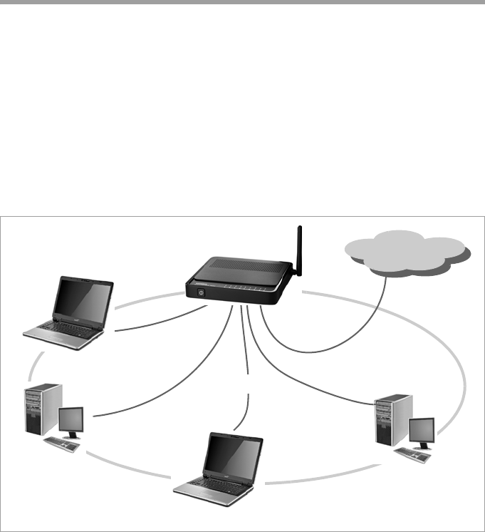
67
Appendix
Wired local area network (Ethernet)
In a wired local area network, PCs communicate with one another via an Ethernet cable.
When the router Gigaset 504 AGU is used, it establishes the connection between the
PCs. For this the 504 series has four Ethernet LAN ports for connecting four PCs. The 501
series has one Ethernet LAN port. The PCs have to be equipped with a network port (Eth-
ernet).
New PCs frequently already have this port. For older PCs you need to install an Ethernet
network card.
The PC and the Ethernet LAN port on the router are connected using an Ethernet cable
(CAT5). One Ethernet cable is supplied. Additional ones can be obtained from your
retailer.
The router Gigaset 504 AGU allows all PCs to access the Internet simultaneously.
Internet
Ethernet

68
Appendix
Wireless local area network (WLAN)
In a wireless local area network (WLAN), PCs are linked without wires or cables. The PCs
have to be equipped with a wireless local area network adapter (WLAN adapter), for
example with a Gigaset USB Adapter 54.
There are two types of wireless network:
uInfrastructure mode
uAd-hoc mode
Infrastructure mode
Infrastructure mode connects wireless and wired networks with one another. In addi-
tion to the mobile stations, infrastructure mode needs an access point such as the router
Gigaset 504 AGU. In infrastructure mode, the stations in the network always communi-
cate via this access point. The access point sets up the wireless network on a permanent
basis. Each station that wants to be part of the wireless network must first register with
the access point before it can exchange data.
The access point establishes the connection between the mobile stations of a wireless
network and a wired LAN (Ethernet) or the Internet. In this case this is described as the
device's router functionality. The router sends data packets that are not addressed to sta-
tions within the network "outside" and forwards data packets originating from "outside"
to the appropriate station within the network.
You can use the router Gigaset 504 AGU to connect
uwirelessly networked PCs to the Internet and
uwirelessly networked PCs to an Ethernet network.
Infrastructure mode is the default configuration for the Gigaset 504 AGU.
Ad-hoc mode
An ad-hoc network is a wireless network that has been configured without an access
point or a router. The mobile network components that communicate with each other
directly and wirelessly form the network on an "ad-hoc" basis, i.e. as and when required.
All the stations in the network have the same rights. Ad-hoc networks are used wher-
ever communications networks have to be set up quickly and there is no existing net-
work infrastructure, and where the participants are on the move.
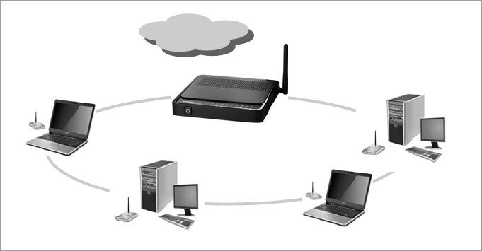
69
Appendix
Linking wireless networks with the Internet
The router Gigaset 504 AGU has an ADSL interface that permits all stations within its
local area network to access the Internet simultaneously. To be able to use this function-
ality, you need a DSL connection obtainable from an Internet service provider. Find out
whether your service provider supports parallel access by several PCs.
Internet
WLAN
(((
(((
(((
(((
)))(((
Internet
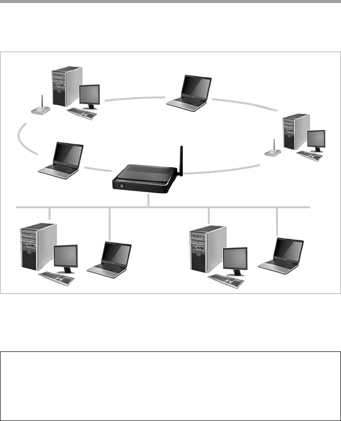
70
Appendix
Linking a wireless network to an Ethernet
Wireless local area networks can work easily together with existing Ethernet networks.
If you wish to connect mobile stations to an existing wired network, you must group
together all mobile stations into a wireless local area network in infrastructure mode.
The devices of the 504 series have four Ethernet interfaces (LAN ports). Up to four PCs
can be directly connected to these LAN ports.
All PCs can access the Internet via the router Gigaset 504 AGU.
Please remember:
You can also connect an Ethernet router or switch to a LAN port to access a larger Eth-
ernet. If you want to link the Gigaset WLAN network to an existing network, a large
number of settings have to be applied. Therefore we cannot provide a general exam-
ple for this use; the configuration depends greatly on the networks in question. We
advise having the configuration of such a network carried out by a specialist.
Access Point
WLAN (wireless)
Ethernet
(wired)
(((
(((
)))
)))
)))(((
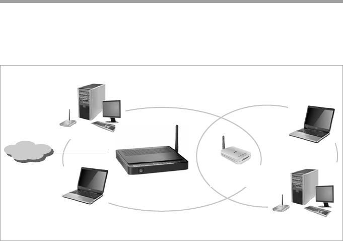
71
Appendix
Extending the wireless network coverage with a repeater
Using the Gigaset WLAN Repeater, you can extend your wireless network's coverage. Set
it up within the range of your network. The repeater will now transmit data traffic into
its own wireless area. This technology allows you to set up wireless networks that cover
a much larger area than is possible with a single router Gigaset 504 AGU.
PCs to be connected in a wireless local area network via a repeater must be equipped
with an integrated wireless network adapter or you have to connect an external wireless
network adapter (e.g. a USB adapter).
Internet
)))
(((
)))
)))
WLAN
(((
Gigaset WLAN
Repeater (((
)))
)))

72
Appendix
Deactivating HTTP proxy and configuring a pop-up blocker
Before you can start the configuration program of the router Gigaset 504 AGU, you
might need to adjust the settings described below for your Web browser.
Deactivating the HTTP proxy
Make sure that the HTTP proxy in your web browser is deactivated. This function must
be deactivated so that your web browser can access your router's configuration pages.
The following section describes the procedure for Internet Explorer and Mozilla Firefox.
Follow the steps for the appropriate browser.
Internet Explorer
ìOpen Internet Explorer and from the Tools menu, select Internet Options.
ìIn the Internet Options window, click the Connections tab.
ìClick LAN Settings.
ìDeactivate all options in the LAN Settings window.
ìClick OK and then OK again to close the Internet Options window.
Mozilla Firefox
ìOpen Mozilla Firefox. Click Tools and then Settings.
ìIn the Settings window, click Connection Settings...
ìIn the Connection Settings window, select the option Direct connection to the
Internet.
ìClick OK to finish.
Configuring the pop-up blocker
You must allow pop-ups for the configuration program in order to start it.
Internet Explorer
If working with Windows XP Service Pack 2, pop-ups are blocked by default. If the con-
figuration program is blocked carry out the following steps:
ìRight-click on the browser information bar.
ìSelect Allow popups from this screen.
ìConfirm the dialogue window by clicking OK.
The configuration screens for the router are now allowed as pop-ups.
You can make additional settings for pop-ups within Internet Explorer via the Tools –
Popup Manager menu item or via Tools – Internet Options on the Privacy tab.

73
Appendix
Mozilla Firefox
Pop-ups are blocked by default. Carry out the following steps:
ìOpen Mozilla Firefox. Click Tools and then Settings.
ìClick on the Content icon.
ìDeactivate the Block Popup window option.
ìClick OK to finish.
Please note:
Should you use a different pop-up blocker, you must configure this accordingly.

74
Appendix
Specifications
Interfaces
1 DSL RJ11, ITU G.992.5, Annex A
4 LAN RJ45, 10Base-T/100Base-TX, Auto-sensing
1 USB USB 1.1, for connection of a PCs
WLAN 802.11g, for wireless connection of up to 252 PCs,
External network adaptor Input 230 V AC, output 9 V, 1A DC
Wireless properties
Frequency range 2400 to 2484 GHz ISM band
(subject to local regulations)
Spreading Direct Sequence Spread Spectrum (DSSS)
Modulation CCK, OFDM
Number of channels IEEE 802.11b: 13 (Europe, ETSI)
IEEE 802.11g: 13 (Europe, ETSI)
Transfer rate IEEE 802.11b: 1, 2, 5.5, 11 Mbps
IEEE 802.11g: 1, 2, 5.5, 6, 9, 11, 12, 18, 24, 36, 48, 54 Mbps
Range Up to 300 m outdoors, up to 50 m indoors
Operating environment
Temperature Operating temperature 0 to 40 °C
Storage temperature –25 to 70°C
Humidity 5% to 90% (non-condensing)
LED displays Power (on/off)
ADSL (operation, synchronisation)
Online (activity, Internet)
WLAN (activity, wireless)
LAN1... LAN4 (connection to PC, activity, wired)
USB (device connection)
Compliance with security conditions and regulations
CE, EN60950

75
Appendix
Authorisation
This device is intended for use worldwide. Use outside the European Economic Area
(with the exception of Switzerland) is subject to national approval. Country-specific
requirements have been taken into consideration.
Cet appareil est destiné pour une utilisation domestique en France.
More information concerning network interface and Annex A / B is available on the prod-
uct label.
The functions described in this user manual are not available in all countries.
We,Gigaset Communications GmbH, declare that this device meets the essential
requirements and other relevant regulations laid down in Directive 1999/5/EC.
A copy of the 1999/5/EC Declaration of Conformity is available at this Internet address:
http://www.gigaset.com/docs
Software Browser-based configuration environment
PPPoE, PPPoA
DHCP server and client, DynDNS
Firewall, prevention of hacker attacks
MAC address filtering
URL filtering, domain blocking
DoS blocking, SPI
NAT
Log file
WEP encryption
WPA-PSK and WPA2-PSK encryption
76
Glossary
Glossary
Access point
An access point, such as the router Gigaset 504 AGU, is the centre of a wireless local net-
work (WLAN). It handles the connection of the wireless linked network components and
regulates the data traffic in the wireless network. The access point also serves as an
interface to other networks, for example an existing Ethernet LAN or via a modem to the
Internet. The operating mode of wireless networks with an access point is called
Infrastructure mode.
Ad-hoc mode
Ad-hoc mode describes wireless local networks (WLANs), in which the network compo-
nents set up a spontaneous network without an Access point, for example several Note-
books in a conference. All the network components are peers. They must have a wire-
less Network adapter.
ADSL /ADSL2+
Asymmetric Digital Subscriber Line (ADSL) and ADSL 2+ are special types of DSL data
transfer technology.
AES
Advanced Encryption Standard
AES is an encryption system, which was published as a standard in October 2000 by the
National Institute of Standards and Technology (NIST). It is used for WPA encryption. A
distinction is made between the three AES variants AES-128, AES-192 and AES-256 on
the basis of the key length.
Auto connect
Auto connect means that applications such as Web browser, Messenger and E-mail
automatically open an Internet connection when they are launched. This can lead to
high charges if you are not using Flat rate. To avoid this, you can select the manual con-
nect option on the router Gigaset 504 AGU.
Bridge
A bridge connects several network segments to form a joint network, for example to
make a TCP/IP network. The segments can have different physical characteristics, for
example different cabling as with Ethernet and wireless LANs. Linking individual seg-
ments via bridges allows local networks of practically unlimited size.
See also: Switch, Hub, Router, Gateway
Broadcast
A broadcast is a data packet not directed to a particular recipient but to all the network
components in the network. The router Gigaset 504 AGU does not pass on broadcast
packets; they always remain within the local network (LAN) it administers.
77
Glossary
BSSID
Basic Service Set ID
BSSID permits unique differentiation of one wireless network (WLAN) from another. In
Infrastructure mode, the BSSID is the MAC address of the Access point. In wireless net-
works in Ad-hoc mode, the BSSID is the MAC address of any one of the participants.
Client
A client is an application that requests a service from a server. For example, an HTTP cli-
ent on a PC in a local network requests data, i.e. Web pages from an HTTP server on the
Internet. Frequently the network component (e.g. the PC) on which the client applica-
tion is running is also called a client.
DHCP
Dynamic Host Configuration Protocol
DHCP handles the automatic assignment of IP addresses to network components. It was
developed because of the complexity involved in defining IP addresses in large networks
– especially the Internet – as participants frequently move, drop out or new ones join.
A DHCP server automatically assigns the connected network components (DHCP Cli-
ents) Dynamic IP addresses from a defined IP pool range thus saving a great deal of con-
figuration work. In addition, the address blocks can be used more effectively: Since not
all participants are on the network at the same time, the same IP address can be
assigned to different network components in succession as and when required.
The router Gigaset 504 AGU includes a DHCP server and uses it to assign automatic IP
addresses to PCs in the local network. You can specify that the IP addresses for certain
PCs are never changed.
DHCP server
See DHCP
DMZ
Demilitarised Zone
DMZ describes a part of a network that is outside the Firewall. A DMZ is set up, as it
were, between a network you want to protect (e.g. a LAN) and a non-secure network
(e.g. the Internet). A DMZ is useful if you want to offer Server services on the Internet
that are not to be run from behind the firewall for security reasons or if Internet appli-
cations do not work properly behind a firewall. A DMZ permits unrestricted access from
the Internet to only one or a few network components, while the other network com-
ponents remain secure behind the firewall.
78
Glossary
DNS
Domain Name System
DNS permits the assignment of IP addresses to computers or Domain names that are
easier to remember. A DNS server must administer this information for each LAN with
an Internet connection. As soon as a page on the Internet is called up, the browser
obtains the corresponding IP address from the DNS server so that it can establish the
connection.
On the Internet, the assignment of domain names to IP addresses follows a hierarchical
system. A local PC only knows the address of the local name server. This in turn knows
all the addresses of the PCs in the local network and the superordinate name servers,
which again know addresses or the next superordinate name servers.
DNS server
See DNS
Domain name
The domain name is the reference to one or more Web servers on the Internet. The
domain name is mapped via the DNS service to the corresponding IP address.
DoS attack
Denial of Service
A DoS attack is a particular form of hacker attack directed at computers and networks
with a connection to the Internet. The aim is not so much to steal data but to paralyse
the computer or network so severely that the network resources are no longer available.
A typical hacker attack involves making a remote computer announce that it is acting for
the paralysed computer, for example, and receive the data intended for you.
DSL
Digital Subscriber Line
DSL is a data transfer technique in which a connection to the Internet can be run at high
speed over normal telephone lines. A DSL connection is provided by an Internet service
provider. It requires a DSL modem.
Dynamic IP address
A dynamic IP address is assigned to a network component automatically by DHCP. This
means that the IP address of a network component can change with every login or at
certain intervals.
See also: Static IP address
79
Glossary
DynDNS
Dynamic DNS
The assignment of Domain names and IP addresses is handled by the Domain Name
Service (DNS). This service is now enhanced with so-called Dynamic DNS (DynDNS) for
Dynamic IP addresses. This enables the use of a network component with a dynamic IP
address as a Server on the Internet. DynDNS ensures that a service can always be
addressed on the Internet under the same domain name regardless of the current IP
address.
Encryption
Encryption protects confidential information against unauthorised access. With an
encryption system, data packets can be sent securely over a network. The router Gigaset
504 AGU offers WEP encryption and WPA for secure data transfer over wireless net-
works.
Ethernet
Ethernet is a network technology for local networks (LANs) defined by the IEEE as stand-
ard IEEE 802.3. Ethernet uses a base-band cable with a transfer rate of 10 or 100 Mbps
or 1 Gbps.
File Server
See Server
Firewall
Firewalls are used by network operators as protection against unauthorised external
access. This involves a whole bundle of hardware and software actions and technologies
that monitor and control the data flow between the private network to be protected and
an unprotected network such as the Internet.
See also: NAT
Flat rate
Flat rate is a particular billing system for Internet connections. The Internet service pro-
vider charges a monthly fee regardless of the duration and number of logins.
FTP (File Transfer Protocol)
FTP is a protocol for exchanging files on the Internet. You can use it, for example, to offer
files for downloading or to receive files from other users.
Full duplex
Data transfer mode in which data can be sent and received at the same time.
See also: Half duplex
Gateway
A gateway is a device for connecting networks with completely different architectures
(addressing, protocols, application interfaces etc.). Although it is not totally correct, the
term is also used as a synonym for Router.
80
Glossary
Global IP address
See Public IP address
Half duplex
Operating mode for data transmission. Only one side can send and/or receive data at
the same time.
See also: Full duplex
HTTP proxy
An HTTP proxy is a Server that network components use for their Internet traffic. All
requests are sent via the proxy.
Hub
A hub connects several network components in a star-topology network by sending all
the data it receives from one network component to all the other network components.
See also: Switch, Bridge, Router, Gateway
IEEE
Institute of Electrical and Electronic Engineers
The IEEE is an international body for defining network standards, especially for stand-
ardising LAN technologies, transfer protocols, data transfer speeds and wiring.
IEEE 802.11
IEEE 802.11 is a standard for wireless LANs operating in the 2.4 GHz or 5 GHz band. In
so-called Infrastructure mode, terminals can be connected to a base station (Access
point) or they can connect with each other spontaneously (Ad-hoc mode).
IGMP
Internet Group Management Protocol
IGMP is an Internet Protocol that enables an Internet computer to inform neighbouring
routers that it is a member of a multicast group. With multicasting, a computer can send
content on the Internet to several other computers that have registered an interest in
the first computer's content. Multicasting can, for example, be used for multimedia pro-
grams for media streaming to recipients that have set up multicast group membership.
Infrastructure mode
Infrastructure mode is a way of operating wireless local networks (WLANs) in which an
Access point handles the data traffic. Network components cannot establish a direct
connection with each other as is the case in Ad-hoc mode.
81
Glossary
Internet
The Internet is a wide-area network (WAN) linking several million users around the
world. A number of Protocols have been created for exchanging data, and these are
known collectively as TCP/IP protocol stack. All participants on the Internet can be iden-
tified by an IP address. Servers are addressed by Domain names (e.g. gigaset.com).
Domain names are assigned to IP addresses by the Domain Name Service (DNS).
These are some of the main Internet services:
uElectronic mail (e-mail)
uThe World Wide Web (WWW)
uFile transfer (FTP)
uDiscussion forums (Usenet / Newsgroups)
Internet service provider
An Internet service provider offers access to the Internet for a fee.
Internet telephony
Transmission of voice via the Internet (Voice over IP).
IP
Internet protocol
The IP Protocol is one of the TCP/IP protocols. It is responsible for addressing parties in a
network using IP addresses and routes data from the sender to the recipient. It decides
the paths along which the data packets travel from the sender to the recipient in a com-
plex network (routing).
IP address
The IP address is the unique network-wide address of a network component in a net-
work based on the TCP/IP protocols (e.g. in a local area network (LAN) or on the Inter-
net). The IP address has four parts (each with up to three-position digit sequences) sep-
arated by full stops (e.g. 192.168.1.1). The IP address comprises the network number
and the computer number. Depending on the Subnet mask, one, two or three parts
form the network number; the remainder form the computer number. You can find out
the IP address of your PC using the ipconfig command.
IP addresses can be assigned manually (see Static IP address) or automatically (see
Dynamic IP address).
On the Internet Domain names are normally used instead of the IP addresses. The DNS
is used to assign domain names to IP addresses.
The router Gigaset 504 AGU has a Private IP address and a Public IP address.
IPoA
IP over ATM
82
Glossary
IP pool range
The IP address pool of the router Gigaset 504 AGU defines a range of IP addresses that
the router's DHCP server can use to assign Dynamic IP addresses.
ISP
(Internet Service Provider)
Internet service provider
LAN
Local network
A local area network (or local network) links network components so that they can
exchange data and share resources. The physical range is restricted to a particular area
(a site). As a rule the users and operators are identical. A local network can be connected
to other local networks or to a wide-area network (WAN) such as the Internet.
With the router Gigaset 504 AGU you can set up a wired local Ethernet network and a
wireless IEEE 802.11g standard network (WLAN).
Local IP address
See Private IP address
MAC address
Media Access Control
The MAC address is used for the globally unique identification of a Network adapters. It
comprises six parts (hexadecimal numbers), e.g. 00-90-96-34-00-1A. The MAC address
is assigned by the network adapter manufacturer and should not be changed.
Mbps
Million bits per second
Specification of the transfer speed in a network.
MER
MAC Encapsulated Routing
MRU
Maximum Receive Unit
The MRU defines the maximum user data volume within a data packet.
MTU
Maximum Transmission Unit
The MTU defines the maximum length of a data packet that can be carried over the net-
work at any one time.
83
Glossary
NAT
Network Address Translation
NAT is a method for converting IP addresses (Private IP addresses) within a network into
one or several Public IP addresses on the Internet. With NAT, several network compo-
nents in a LAN can share the router's public IP address to connect to the Internet. The
network components of the local network are hidden behind the router's IP address reg-
istered on the Internet. Because of this security function, NAT is frequently used as part
of the Firewall of a network. If you want to make services on a PC in the local network
available on the Internet despite NAT, you can configure the router Gigaset 504 AGU as
a Virtual server.
Network
A network is a group of devices connected in wired or wireless mode so that they can
share resources such as data and peripherals. A general distinction is made between
local networks (LANs) and wide-area networks (WANs).
Network adapter
The network adapter is the hardware device that creates the connection between a net-
work component and a local network. The connection can be wired or wireless. An Eth-
ernet network card is an example of a wired network adapter. The Gigaset PC Card 54
and the Gigaset USB Adapter 54 are examples of wireless network adapters.
A network adapter has a unique address, the MAC address.
Public IP address
The public IP address (also known as the global IP address) is a network component's
address on the Internet. It is assigned by the Internet service provider. Devices that cre-
ate a link from a LAN to the Internet, such as the router Gigaset 504 AGU, have a public
and a Private IP address.
Port
Data is exchanged between two applications in a network across a port. The port
number addresses an application within a network component. The combination of IP
address/port number uniquely identifies the recipient or sender of a data packet within
a network. Some applications (e.g. Internet services such as HTTP or FTP) work with
fixed port numbers; others are allocated a free port number whenever they need one.
Port forwarding
In port forwarding, the router Gigaset 504 AGU directs data packets from the Internet
that are addressed to a particular Port to the corresponding port of the appropriate net-
work component. This enables servers within the local network to offer services on the
Internet without them needing a Public IP address.
See also: Virtual server
84
Glossary
PPPoA
Point-to-Point Protocol over ATM
PPPoA is a Protocol for connecting network components in a local Ethernet network to
the Internet via an ATM network.
PPPoE
Point-to-Point Protocol over Ethernet
PPPoE is a Protocol for connecting network components in a local Ethernet network to
the Internet via a modem.
Print server
See Server
Private IP address
The private IP address (also known as the local IP address) is a network component's
address within the local network (LAN). The network operator can assign any address
he or she wants. Devices that act as a link from a local network, such as the router
Gigaset 504 AGU, have a private and a Public IP address.
Protocol
A protocol describes the agreements for communicating in a network. It contains rules
for opening, administering and closing a connection, as well as in relation to data for-
mats, time frames and possibly troubleshooting. Communication between two applica-
tions requires different protocols at various levels, for example the TCP/IP protocols for
the Internet.
PVC
Permanent Virtual Circuit
A permanent virtual circuit is a logical connection in an ATM network.
QoS
Quality of Service
QoS allows network traffic to be sorted according to priorities. When this parameter is
activated, Internet telephony is given priority over other data traffic. This is a precondi-
tion for problem-free calls.
Radio network
See WLAN
Rekey interval
The rekey interval is the period after which new keys are automatically generated for
data encryption with WPA-PSK.
Remote management
Remote management refers to the ability to manage a network from a network compo-
nent that is actually outside the local network (LAN).
85
Glossary
Repeater
A repeater extends the range of a wireless local network by relaying data from the
Access point to additional PCs or Network adapters.
Roaming
Roaming extends the range of a wireless LAN by using several Access points that use the
same SSID and the same radio channel and are linked via Ethernet. The PCs in the net-
work can switch dynamically between several access points without losing the existing
network connection.
Router
A router directs data packets from one local network (LAN) to another via the fastest
route. A router makes it possible to connect networks that have different network tech-
nologies. For example, it can link a local network with Ethernet or WLAN technology to
the Internet.
See also: Bridge, Switch, Hub, Gateway
Server
A server makes a service available to other network components (Clients). The term
"server" is often used to refer to a computer or PC. However, it can also mean an appli-
cation that provides a particular service such as DNS, Web server, file server or print
server.
SMTP
Simple Mail Transfer Protocol
The SMTP Protocol is part of the TCP/IP protocol family. It governs the exchange of elec-
tronic mail on the Internet. Your Internet service provider provides you with access to an
SMTP server.
SNMP
Simple Network Management Protocol
The SNMP Protocol is part of the TCP/IP protocol family. It provides a simple procedure
for administering the network based on a system of shared information for manage-
ment data and network management messages (known as traps) and reports the occur-
rence of events within the monitored network (e.g. an alarm message or notification of
configuration changes).
SPI
Stateful Packet Inspection
Your device uses SPI to monitor and limit access by traffic incoming from the Internet.
This allows it to identify and block certain types of attack such as Denial of Service (DoS).
A typical DoS attack may involve a remote computer paralysing a system and then
claiming to be the paralysed device in order to receive data intended for it.
86
Glossary
SSID
Service Set Identifier
The SSID is used to identify the stations in a wireless network (WLAN). All wireless net-
work components with the same SSID form a common network. The SSID can be
assigned by the network operator.
Static IP address
A static IP address is assigned to a network component manually during network con-
figuration. Unlike the Dynamic IP address, a static (fixed) IP address never changes.
Subnet
A subnet divides a network into smaller units.
Subnet mask
The subnet mask determines how parts of IP addresses of a network represent the net-
work number and how many the computer number.
If the subnet mask is in a network that is administered by the router Gigaset 504 AGU,
for example 255.255.255.0, that means the first three parts of the IP address form the
network number and only the final part can be used for assigning host numbers. The
first three parts of the IP address of all network components are therefore always the
same in this case.
Switch
A switch, like a Hub, is an element used to link different network segments or compo-
nents. Unlike a hub however, the switch has its own intelligence that enables it to for-
ward packets to only the subnet or network component they are meant for.
See also: Bridge, Hub, Router, Gateway
TCP
Transmission Control Protocol
The TCP Protocol is part of the TCP/IP protocol family. TCP handles data transport
between communication partners (applications). TCP is a session-based transfer proto-
col, i.e. it sets up, monitors and terminates a connection for transferring data.
See also: UDP
TCP/IP
Protocol family on which the Internet is based. IP forms the basis for every computer-to-
computer connection. TCP provides applications with a reliable transmission link in the
form of a continuous data stream. TCP/IP is the basis on which services such as WWW,
Mail and News are built. There are other protocols as well.
87
Glossary
UDP
User Datagram Protocol
UDP is a Protocol of the TCP/IP protocol family that handles data transport between two
communication partners (applications). Unlike TCP, UDP is a non-session based proto-
col. It does not establish a fixed connection. The recipient is responsible for making sure
the data is received. The sender is not notified about whether it is received or not.
UPnP
Universal Plug and Play
UPnP technology is used for the spontaneous linking of home or small office networks.
Devices that support UPnP carry out their network configuration automatically once
they are connected to a network. They also provide their own services or use services of
other devices in the network automatically.
URL
Universal Resource Locator
Globally unique address of a domain on the Internet.
VCI
Virtual Channel Identifier
Part of an address in an ATM network.
Virtual server
A virtual Server provides a service on the Internet that runs not on itself, but on another
network component. The router Gigaset 504 AGU can be configured as a virtual server.
It will then direct incoming calls for a service via Port forwarding directly to the appro-
priate Port of the network component in question.
VLAN
Virtual Local Area Network
A VLAN is a virtual local network within a physical network. A widely disseminated tech-
nical implementation of VLANs is defined partially in the Standard IEEE 802.1Q. VLAN
allows preferred forwarding of voice data, for example. This functionality is important
for VoIP (IP telephony). This also means that phone calls can be made without interrup-
tion with a restricted bandwidth.
VoIP
Voice over IP
See Internet telephony
VPI
Virtual Path Identifier
Part of an address in an ATM network.
88
Glossary
WAN
Wide Area Network
A WAN is a wide area network that is not restricted physically to a particular area, for
example the Internet. A WAN is run by one or more public providers to enable private
access. You access the Internet via an Internet service provider.
WDS
Wireless Distribution System
WDS describes the wireless connection between a number of access points.
Web server
See Server
WEP
Wired Equivalent Privacy
WEP is a security protocol defined in the IEEE 802.11 standard. It is used to protect wire-
less transmissions in a WLAN against unauthorised access through Encryption of the
data transmitted.
WLAN
Wireless LAN
Wireless LANs enable network components to communicate with a network using radio
waves as the transport medium. A wireless LAN can be connected as an extension to a
wired LAN or it can form the basis for a new network. The basic element of a wireless
network is the cell. This is the area where the wireless communication takes place. A
WLAN can be operated in Ad-hoc mode or Infrastructure mode.
WLAN is currently specified in Standard IEEE 802.11. The router Gigaset 504 AGU com-
plies with Standard 802.11g.
WPA
WPA is a standard-compliant solution for greater security in wireless networks. WPA is
meant to replace the existing WEP standard (Wired Equivalent Privacy) and offers more
reliable encryption and authentication methods.
WPA-PSK
WPA Pre-shared Key
Variant of WPA data encryption in which new keys are automatically generated at regu-
lar intervals by means of a keyword (pre-shared key). The key is updated after defined
periods (Rekey interval).
89
Index
Index
Numerics
10/100 Mbps switch port. . . . . . . . . . . 9
128-bit encryption. . . . . . . . . . . . . . . 43
128-bit key . . . . . . . . . . . . . . . . . . . . 42
64-bit key . . . . . . . . . . . . . . . . . . . . . 42
A
Access control . . . . . . . . . . . . . . . 28, 45
blocking services . . . . . . . . . . . . . . 29
local area network . . . . . . . . . . . . . 45
Access point . . . . . . . . . . . . . 39, 68, 76
Address block for
IP addresses . . . . . . . . . . . . . . . . 38
Ad-hoc mode. . . . . . . . . . . . . . . . 68, 76
Ad-hoc network. . . . . . . . . . . . . . . . . 68
ADSL interface. . . . . . . . . . . . . . . . . . 69
ADSL modem
integrated . . . . . . . . . . . . . . . . . . . . 4
ADSL port . . . . . . . . . . . . . . . . . . . . . . 9
ADSL/ADSL2+ . . . . . . . . . . . . . . . . . . . 4
Advanced Settings. . . . . . . . . . . . . . . 22
AES . . . . . . . . . . . . . . . . . . . . . . . . . . 76
Antenna . . . . . . . . . . . . . . . . . . . . . . 12
ASCII key . . . . . . . . . . . . . . . . . . . . . . 43
Authorisation . . . . . . . . . . . . . . . . . . 75
Auto connect. . . . . . . . . . . . . . . . . . . 76
B
Backing up configuration data . . . . . . 53
Backup . . . . . . . . . . . . . . . . . . . . . . . 53
Base station see Access point
Bridge . . . . . . . . . . . . . . . . . . . . . . . . 76
Broadcast . . . . . . . . . . . . . . . . . . 40, 76
Browser . . . . . . . . . . . . . . . . . . . . . . . 18
BSSID. . . . . . . . . . . . . . . . . . . . . . . . . 77
Buttons . . . . . . . . . . . . . . . . . . . . . . . 21
C
Client . . . . . . . . . . . . . . . . . . . . . . . . 77
Command
ping . . . . . . . . . . . . . . . . . . . . . . . . 64
Configuration . . . . . . . . . . . . . . . . . . 18
resetting to factory setting . . . . . . . 53
restoring . . . . . . . . . . . . . . . . . . . . . 53
Configuration file. . . . . . . . . . . . . . . . 53
Configuring popup blocker. . . . . . . . . 72
Connection mode. . . . . . . . . . . . . . . . 26
Connection on request . . . . . . . . . . . . 26
Connection type. . . . . . . . . . . . . . . . . 24
ADSL. . . . . . . . . . . . . . . . . . . . . . . . 24
Country settings. . . . . . . . . . . . . . . . . 49
D
Data encryption . . . . . . . . . . . . . . . . . 42
Deactivating the HTTP proxy. . . . . . . . 72
DHCP . . . . . . . . . . . . . . . . . . . . . . . . . 77
DHCP server . . . . . . . . . . . . . . . . . 38, 77
Digital Subscriber Line see DSL
Displaying the operating state . . . . 8, 16
DMZ. . . . . . . . . . . . . . . . . . . . . . . . 6, 77
DNS . . . . . . . . . . . . . . . . . . . . . . . . . . 78
DNS server . . . . . . . . . . . . . . . . . . . . . 78
Domain name . . . . . . . . . . . . . . . . . . 78
Domain Name Service see DNS
DoS attack . . . . . . . . . . . . . . . . . . . . . 78
DSL . . . . . . . . . . . . . . . . . . . . . . . . . . 78
Dynamic DNS see DynDNS
Dynamic Host Configuration Protocol,
see DHCP
Dynamic IP address . . . . . . . . . . . . . . 78
DynDNS . . . . . . . . . . . . . . . . . . . . 35, 79
DynDNS service, see DynDNS
DynDNS.org . . . . . . . . . . . . . . . . . . . . 35
E
ECO . . . . . . . . . . . . . . . . . . . . . . . . . . . 5
Encryption . . . . . . . . . . . . . . . . . . 42, 79
Ethernet. . . . . . . . . . . . . . . 5, 67, 68, 79
transmission speed . . . . . . . . . . . . . . 5
Ethernet network
linking with
a wireless network. . . . . . . . . . . . 70
Exposed host . . . . . . . . . . . . . . . . . . . 34
Extending wireless coverage . . . . . . . 71
90
Index
F
Features . . . . . . . . . . . . . . . . . . . . . . . 5
Firewall . . . . . . . . . . . . . . . . . . . . . 5, 79
activating/deactivating . . . . . . . . . . 28
configuring . . . . . . . . . . . . . . . . . . 28
Firmware
current version. . . . . . . . . . . . . . . . 54
updating . . . . . . . . . . . . . . . . . . . . 54
Flat rate. . . . . . . . . . . . . . . . . . . . . . . 79
Full duplex. . . . . . . . . . . . . . . . . . . . . 79
G
Gateway . . . . . . . . . . . . . . . . . . . . . . 79
Gigaset SX76x WLAN dsl
default settings . . . . . . . . . . . . . . . 11
installation. . . . . . . . . . . . . . . . . . . 12
IP address. . . . . . . . . . . . . . . . . . . . 18
possibilities for network setup . . . . 66
rear panel. . . . . . . . . . . . . . . . . . . . . 9
setting up. . . . . . . . . . . . . . . . . . . . . 8
Global IP address see Public IP address
H
Hacker attacks . . . . . . . . . . . . . . . . 5, 78
Half duplex . . . . . . . . . . . . . . . . . . . . 80
Help . . . . . . . . . . . . . . . . . . . . . . . . . 21
Hexadecimal key . . . . . . . . . . . . . . . . 43
HTTP proxy . . . . . . . . . . . . . . . . . . . . 80
Hub . . . . . . . . . . . . . . . . . . . . . . . . . . 80
I
Idle time . . . . . . . . . . . . . . . . . . . . . . 51
IEEE. . . . . . . . . . . . . . . . . . . . . . . . . . 80
Infrastructure mode. . . . . . . . . . . 68, 80
Installation . . . . . . . . . . . . . . . . . . . . 12
Institute of Electrical and Electronic
Engineers see IEEE
Internet . . . . . . . . . . . . . . . . . 23, 81, 82
connection mode . . . . . . . . . . . . . . 26
connection on request . . . . . . . . . . 26
connection type . . . . . . . . . . . . . . . 24
manual connection . . . . . . . . . . . . 26
menu . . . . . . . . . . . . . . . . . . . . . . . 23
setting up access control . . . . . . . . 28
setting up multiple connection
services . . . . . . . . . . . . . . . . . . . 24
Internet access . . . . . . . . . . . . . . . . . . 5
Internet connection
changing configuration. . . . . . . . . . 25
closing manually. . . . . . . . . . . . . . . 20
disconnecting automatically . . . . . . 26
opening manually. . . . . . . . . . . . . . 20
setting up . . . . . . . . . . . . . . . . . . . . 25
Internet Explorer . . . . . . . . . . . . . 11, 18
Internet protocol see IP protocol
Internet service provider . . . . . . . 81, 82
Internet time . . . . . . . . . . . . . . . . . . . 50
IP address. . . . . . . . . . . . . . . . . . . 37, 81
address block . . . . . . . . . . . . . . . . . 38
assigning automatically . . . . . . . . . 37
assigning static . . . . . . . . . . . . . . . . 38
dynamic . . . . . . . . . . . . . . . . . . . . . 78
Gigaset SX76x WLAN dsl . . . . . . . . . 18
private . . . . . . . . . . . . . . . . . . . . . . 84
public . . . . . . . . . . . . . . . . . . . . . . . 83
static . . . . . . . . . . . . . . . . . . . . . . . 86
IP address block for DHCP . . . . . . . . . . 38
IP address pool . . . . . . . . . . . . . . . . . . 82
IP protocol . . . . . . . . . . . . . . . . . . . . . 81
IPoA . . . . . . . . . . . . . . . . . . . . . . . . . . 81
ISP see Internet service provider
K
Key length
128 bit (ASCII) . . . . . . . . . . . . . . . . 43
64 bit (ASCII) . . . . . . . . . . . . . . . . . 43
64 bit (hexadecimal). . . . . . . . . . . . 43
L
Label . . . . . . . . . . . . . . . . . . . . . . . . . 10
LAN . . . . . . . . . . . . . . . . . . . . . . . 70, 82
configuration . . . . . . . . . . . . . . . . . 37
LAN port . . . . . . . . . . . . . . . . . . . . . . . 9
Lease time . . . . . . . . . . . . . . . . . . . . . 38
LED
behaviour after initial connection . . 16
LED displays . . . . . . . . . . . . . . . . . . . . 16
Local area network see LAN
Local IP address see
Private IP address
Login screen. . . . . . . . . . . . . . . . . . . . 18
M
MAC access control list . . . . . . . . . . . . 45
91
Index
MAC address . . . . . . . . . . . . . . . . . . . 82
MAC Encapsulated Routing
see MER
Mains adapter
port . . . . . . . . . . . . . . . . . . . . . . . . . 9
Mains adapter port . . . . . . . . . . . . . . . 9
Manual connection . . . . . . . . . . . . . . 26
Maximum Receive Unit see MRU
Maximum Transmission Unit see MTU
Mbps . . . . . . . . . . . . . . . . . . . . . . . . . 82
MER. . . . . . . . . . . . . . . . . . . . . . . . . . 82
Mobile network . . . . . . . . . . . . . . . . . 68
Mozilla Firefox . . . . . . . . . . . . . . . 11, 18
MRU . . . . . . . . . . . . . . . . . . . . . . . . . 82
MTU . . . . . . . . . . . . . . . . . . . . . . . . . 82
N
NAT . . . . . . . . . . . . . . . . . . . . . . . 30, 83
port forwarding . . . . . . . . . . . . . . . 31
Network . . . . . . . . . . . . . . . . . . . . . . 83
ad-hoc . . . . . . . . . . . . . . . . . . . . . . 68
infrastructure . . . . . . . . . . . . . . . . . 68
wired . . . . . . . . . . . . . . . . . . . . . . . 67
wireless . . . . . . . . . . . . . . . . . . . . . 68
Network adapter . . . . . . . . . . . . . . . . 83
wireless . . . . . . . . . . . . . . . . . . . . . 68
Network Address Translation . . . . 30, 83
Network component
mobile . . . . . . . . . . . . . . . . . . . . . . 68
New encryption. . . . . . . . . . . . . . . . . 41
P
Password . . . . . . . . . . . . . . . . . . . . . . 18
Permanent Virtual Circuit see PVC
ping. . . . . . . . . . . . . . . . . . . . . . . . . . 64
Point-to-Point Protocol over ATM
see PPPoA
Point-to-Point Protocol over Ethernet
see PPPoE
Popup blocker . . . . . . . . . . . . . . . . . . 72
Port . . . . . . . . . . . . . . . . . . . . . . . . . . 83
for DSL modem . . . . . . . . . . . . . . . . 9
for mains adapter . . . . . . . . . . . . . . . 9
LAN . . . . . . . . . . . . . . . . . . . . . . . . . 9
USB, for PC. . . . . . . . . . . . . . . . . . . . 9
Port forwarding . . . . . . . . . . . . . . 31, 83
setting up. . . . . . . . . . . . . . . . . . . . 32
Port number. . . . . . . . . . . . . . . . . 33, 83
illustration . . . . . . . . . . . . . . . . . . . 32
PPPoE. . . . . . . . . . . . . . . . . . . . . . . . . 84
Private IP address . . . . . . . . . . . . . . . . 84
Problem solving . . . . . . . . . . . . . . . . . 62
Protocol . . . . . . . . . . . . . . . . . . . . . . . 84
Public IP address. . . . . . . . . . . . . . . . . 83
PVC . . . . . . . . . . . . . . . . . . . . . . . . . . 84
Q
Quality of Service (QoS) . . . . . . . . 36, 84
R
Radio network . . . . . . . . . . . . . . . . . . 88
infrastructure mode . . . . . . . . . . . . 68
Radio settings . . . . . . . . . . . . . . . . . . 39
Rear panel . . . . . . . . . . . . . . . . . . . . . . 9
Reboot . . . . . . . . . . . . . . . . . . . . . 10, 53
Reboot function . . . . . . . . . . . . . . . . . 10
Remote management. . . . . . . . . . 51, 84
Repeater . . . . . . . . . . . . . . . . . . . 46, 71
Reset button . . . . . . . . . . . . . . . . . . . 10
Reset function . . . . . . . . . . . . . . . . . . 10
Resetting . . . . . . . . . . . . . . . . . . . . . . 53
Roaming . . . . . . . . . . . . . . . . . . . . . . 85
Router . . . . . . . . . . . . . . . . . . . . . . . . 85
dynamic IP address . . . . . . . . . . . . . 35
IP address . . . . . . . . . . . . . . . . . . . . 37
setting up a local area network . . . . 66
S
Security architecture, WEP . . . . . . . . . 42
Security functions . . . . . . . . . . . . . . . . 5
Security measures . . . . . . . . . . . . . . . . 5
Server . . . . . . . . . . . . . . . . . . . . . . . . 85
virtual. . . . . . . . . . . . . . . . . . . . . . . 87
Service Set Identifier see SSID
Setting up . . . . . . . . . . . . . . . . . . . . . . 8
Simple Mail Transfer Protocol see SMTP
Simple Network Management Protocol
see SNMP
SMTP . . . . . . . . . . . . . . . . . . . . . . . . . 85
SNMP . . . . . . . . . . . . . . . . . . . . . . . . . 85
Specifications. . . . . . . . . . . . . . . . . . . 74
SPI . . . . . . . . . . . . . . . . . . . . . . . . . . . 85
Splitter . . . . . . . . . . . . . . . . . . . . . 13, 14
SSID . . . . . . . . . . . . . . . . . . . . . . . 44, 86
92
Index
concealed . . . . . . . . . . . . . . . . . . . 40
visible . . . . . . . . . . . . . . . . . . . . . . 40
SSID broadcast. . . . . . . . . . . . . . . . . . 40
Start screen . . . . . . . . . . . . . . . . . . . . 19
Stateful Packet Inspection . . . . . . . . . 85
Static IP address. . . . . . . . . . . . . . . . . 86
Status
device . . . . . . . . . . . . . . . . . . . . . . 61
local area network . . . . . . . . . . . . . 59
overview . . . . . . . . . . . . . . . . . . . . 56
security . . . . . . . . . . . . . . . . . . . . . 57
wireless network . . . . . . . . . . . . . . 60
Status information. . . . . . . . . . . . . . . 56
Subnet. . . . . . . . . . . . . . . . . . . . . . . . 86
Subnet mask . . . . . . . . . . . . . . . . . . . 86
Switch . . . . . . . . . . . . . . . . . . . . . . . . 86
System log. . . . . . . . . . . . . . . . . . . . . 55
System management. . . . . . . . . . . . . 51
phone-based . . . . . . . . . . . . . . . . . 51
System password
assigning . . . . . . . . . . . . . . . . . . . . 50
changing . . . . . . . . . . . . . . . . . . . . 50
System requirements. . . . . . . . . . . . . 11
System time . . . . . . . . . . . . . . . . . . . 50
T
TCP . . . . . . . . . . . . . . . . . . . . . . . . . . 86
TCP/IP . . . . . . . . . . . . . . . . . . . . . . . . 86
Time server . . . . . . . . . . . . . . . . . . . . 50
Trademarks . . . . . . . . . . . . . . . . . . . . 11
Transmission Control Protocol see TCP
Transmission mode . . . . . . . . . . . . . . 40
Transmission speed . . . . . . . . . . . . . . 82
in the Ethernet LAN . . . . . . . . . . . . . 5
in wireless LAN. . . . . . . . . . . . . . . . . 5
Troubleshooting . . . . . . . . . . . . . . . . 62
U
UDP . . . . . . . . . . . . . . . . . . . . . . . . . . 87
Universal Plug and Play see UPnP
Universal Resource Locator see URL
UPnP . . . . . . . . . . . . . . . . . . . . . . 27, 87
enabling . . . . . . . . . . . . . . . . . . . . . 27
URL . . . . . . . . . . . . . . . . . . . . . . . . . . 87
URL filter . . . . . . . . . . . . . . . . . . . . . . 29
USB port for PC. . . . . . . . . . . . . . . . . . . 9
User Datagram Protocol see UDP
User interface
buttons. . . . . . . . . . . . . . . . . . . . . . 21
elements . . . . . . . . . . . . . . . . . . . . 21
Help . . . . . . . . . . . . . . . . . . . . . . . . 21
idle time . . . . . . . . . . . . . . . . . . . . . 51
logout. . . . . . . . . . . . . . . . . . . . . . . 21
starting. . . . . . . . . . . . . . . . . . . . . . 18
V
VCI . . . . . . . . . . . . . . . . . . . . . . . . . . . 87
Virtual Channel Identifier see VCI
Virtual Path Identifier see VPI
Virtual server . . . . . . . . . . . . . . 6, 32, 87
Voice over IP see Internet telephony
VPI . . . . . . . . . . . . . . . . . . . . . . . . . . . 87
W
WAN . . . . . . . . . . . . . . . . . . . . . . . . . 88
WDS. . . . . . . . . . . . . . . . . . . . . . . . . . 46
WEP . . . . . . . . . . . . . . . . . . . . 41, 42, 88
encryption mode . . . . . . . . . . . . . . 42
key length. . . . . . . . . . . . . . . . . . . . 43
Wide Area Network see WAN
Wired Equivalent Privacy see WEP
Wired network . . . . . . . . . . . . . . . . . . 67
Wireless cell . . . . . . . . . . . . . . . . . . . . 88
Wireless LAN see WLAN
Wireless network
ad-hoc mode . . . . . . . . . . . . . . . . . 68
WLAN. . . . . . . . . . . . . . . . . . . 68, 70, 88
operating modes . . . . . . . . . . . . . . 68
transmission speed . . . . . . . . . . . . . . 5
WLAN adapter . . . . . . . . . . . . . . . . . . 68
WPA . . . . . . . . . . . . . . . . . . . . . . . 41, 88
pre-shared key . . . . . . . . . . . . . . . . 88
WPA2-PSK . . . . . . . . . . . . . . . . . . . . . 41
WPA-PSK . . . . . . . . . . . . . . . . . . . . . . 41

Issued by
Gigaset Communications GmbH
Schlavenhorst 66, D-46395 Bocholt
Gigaset Communications GmbH is a trademark licensee of Siemens AG.
© Gigaset Communications GmbH 2008
All rights reserved. Subject to availability.
Rights of modification reserved.
www.gigaset.com
A31008-N1216-A501-1X-7619
