Siemens Isi En 50295 Users Manual 01_Titel+Umschlag_IKPI_2004_eng_30mm.FH10
EN 50295 to the manual d3d1be28-b3fd-4598-bc00-3b83c2690a82
2015-02-05
: Siemens Siemens-Isi-En-50295-Users-Manual-410336 siemens-isi-en-50295-users-manual-410336 siemens pdf
Open the PDF directly: View PDF ![]() .
.
Page Count: 152 [warning: Documents this large are best viewed by clicking the View PDF Link!]
- AS-Interface
- A/B technique
- AS-Interface Safety at work
- Introduction
- AS-Interface safety monitors
- AS-Interface safe compact modules
- AS-Interface position switches
- AS-Interface cable-operated switches
- AS-Interface light curtains and light arrays for Category 4
- AS-Interface laser scanner LS4
- AS-Interface EMERGENCY STOP pushbuttons
- AS-Interface Master
- I/O modules for operation in the field
- I/O modules for operation in IP20 control cabinet
- Special integrated solutions
- Modules with special functions
- AS-Interface compact starters IP65 (400 V AC)
- SIGNUM pushbuttons and indicator light
- AS-Interface for LOGO!
- AS-Interface Power Supply Units
- Transmission media
- System components and accessories
AS-Interface
according to EN 50295
Siemens IK PI . 2004
6/2 Introduction
6/2 Transmission technology
6/3 Configuration example
6/4 System components
6/5 Technical specifications
6/6 A/B technique
6/8 AS-Interface Safety at work
6/8 Introduction
6/9 AS-Interface safety monitors
6/11 AS-Interface safe compact modules
6/15 AS-Interface position switches
6/18 AS-Interface cable-operated switches
6/19 AS-Interface light curtains and
light arrays for Category 4
6/24 AS-Interface laser scanner LS4
6/30 AS-Interface EMERGENCY STOP
pushbuttons
6/30 Accessories
AS-Interface Master
6/31 Masters for SIMATIC S5
6/31 CP 2430
6/33 Masters for SIMATIC S7
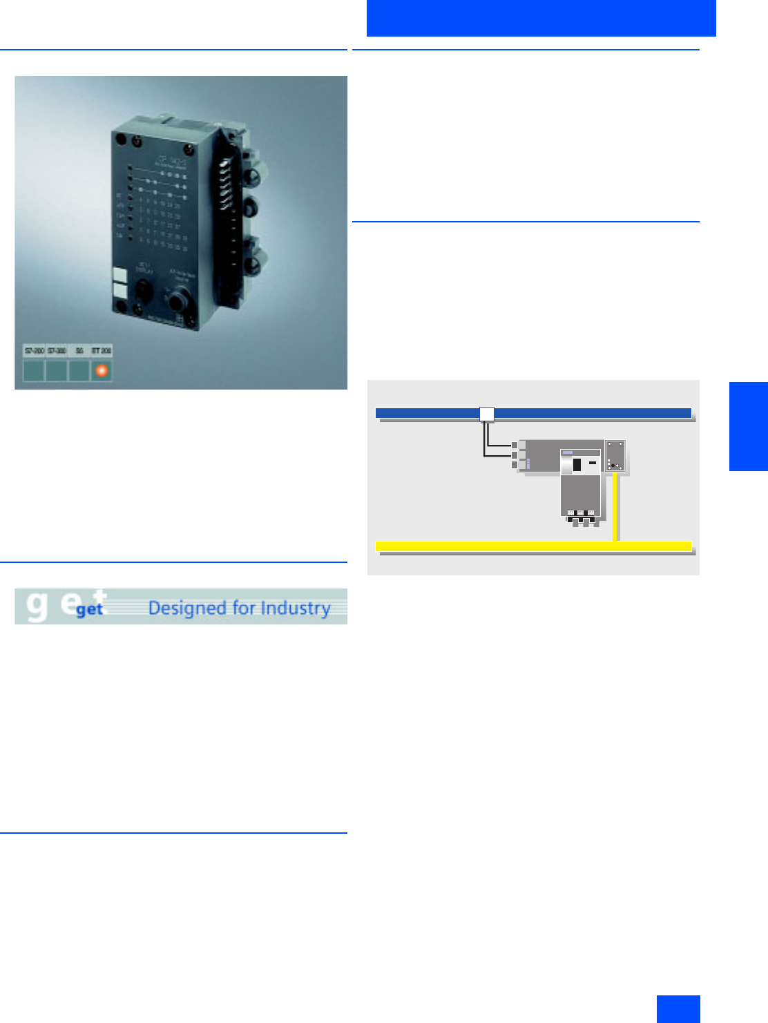
6/33 CP 142-2
6/35 CP 243-2
6/37 CP 343-2
6/39 CP 343-2 P
ST 70 1)Masters for SIMATIC C7
Sec. 8 2)AS-Interface network transitions
DP/AS Interface Link 20E
DP/AS Interface Link 65
AS-Interface Slaves
6/41 I/O modules for operation in the field
6/41 Introduction
6/43 Digital I/O modules IP67 – K60
6/51 Digital I/O modules IP68 / IP69K – K60R
6/56 Digital I/O modules IP67 – K45
6/64 Digital I/O modules IP67 –
application modules
6/71 Analog I/O modules IP67 – K60
6/74 Pneumatic I/O modules
6/75 I/O modules for operation
in IP20 control cabinet
6/75 Introduction
6/77 SlimLine
6/88 F90 module
6/93 Flat module
6/94 Special integrated solutions
6/94 AS-Interface Communication modules
AS-Interface Slaves (continued)
6/98 Modules with special functions
6/98 Counter modules
6/100 Earth fault detection modules
6/103 Overvoltage protection module
6/105 AS-Interface motor starters and
IP65/67 load feeders
6/105 AS-Interface compact starters IP65
(400 V AC)
6/113 AS-Interface motor starters IP67 (24 V DC)
6/116 ECOFAST motor and soft starter
6/117 AS-Interface motor starters and
IP20 load feeders
6/117 Load feeder modules IP20
LV 10 3)AS-Interface Direct/Reverse Starter
6/121 SIRIUS soft starters
LV 10 3)Communications capable contactors
55 to 250 kW
LV 10 3)Double relays and transformers
6/122 SIGNUM pushbuttons and
indicator lights
6/122 AS-Interface F-Adapter for
EMERGENCY STOP command devices
6/123 AS-Interface enclosure
6/124 AS-Interface customized enclosures
and front panel modules
6/133 AS-Interface LED displays
6/134 AS-Interface for LOGO!
LV 10 3)AS-Interface signal columns
6/135 AS-Interface power supply units
6/135 Introduction
6/136 Power supply units IP20
6/141 Power supply units IP65
6/143 Transmission media
6/143 AS-Interface shaped cable
6/145 System components and accessories
6/145 Repeater/Extender
6/147 Addressing units
6/149 Diagnostic units
6/151 Miscellaneous accessories
6/152 Documentation
1)see Catalog ST 70
”Products for Totally Integrated
Automation and Micro Automation“
2)see Section 8
3)see Catalog LV 10
”Controlgear for Industry“
Siemens IK PI · 2004
6/2
AS-Interface
Transmission technology
Introduction
6
■
Overview
Transmission method
A significant feature of the AS-Interface technology is the use of
a common, two-wire cable for data transmission and distribution
of auxiliary power to sensors/actuators.
An AS-Interface power supply unit, which meets the require-
ments of the AS-Interface transmission technology, is used for
this system. The AS-Interface shaped cable provides mechani-
cal coding and thus prevents polarity reversal; penetration
terminals are used for simple contacting.
■
Benefits
Cabinets that were previously overflowing with complicated con-
trol line wiring and marshalling distributors can now be replaced
by AS-Interface.
The AS-Interface cable can be connected at any point, thanks to
specially developed wiring and connection using the insulation
displacement method.
This concept gives you tremendous flexibility and considerably
cuts costs.
The AS-Interface is a single master system. Communications
processors (CPs) are available for SIMATIC® systems which
control process or field communication as masters.
The system expansion now allows double the quantity of slaves
(max. 62) to be operated on AS-Interface. The analog values are
now also preprocessed in the master. For direct connection of
AS-Interface to PROFIBUS DP, DP/AS-Interface Link 20E is
available. Using this DP/AS-Interface link, the AS-Interface can
be used as a subnet for PROFIBUS DP.
The AS-Interface is an open standard. Leading manufacturers
of actuators and sensors support AS-Interface worldwide.
Interested companies can obtain the electrical and mechanical
specifications from the AS-Interface Association on request.
$6,QWHUIDFH
Siemens IK PI · 2004 6/3
AS-Interface
Introduction
Configuration examples
6
■
Function
Operating modes
In general, the master interfaces distinguish between the follow-
ing operating modes:
I/O data transfer
The inputs and outputs of the binary AS-Interface slaves are
read and written in this operating mode.
Analog value transmission
The AS-Interface masters according to the Complete
AS-Interface Specification V2.1 support integrated analog value
processing. This means that data exchange with analog
AS-Interface slaves (according to analog profile 7.3 or 7.4) is just
as easy as with digital slaves.
Command interface
In addition to the I/O data exchange with binary and analog AS-
Interface slaves, the AS-Interface masters offer a range of addi-
tional functions through the command interface.
This means that, from user programs, slave addresses can be
assigned, parameter values can be transferred and diagnostic
information can be read out.
■
Design
Process or field communication
AS-Interface is used wherever individual actuators and sensors
are physically distributed throughout the machine (e.g. in a bot-
tling plant or on a production line).
AS-Interface replaces complicated wiring harnesses and con-
nects binary and analog actuators and sensors, such as proxim-
ity switches, valves or indicator lights, to a controller (e.g. SI-
MATIC) or PC.
In practice this means: The installation runs without problems
because data and power are transported through a single com-
mon cable. No specialist know-how is required for installation
and startup. In addition, the simple installation and clear struc-
turing of the wiring and special cable design not only consider-
ably reduce the risk of faults but also reduce service and main-
tenance costs.
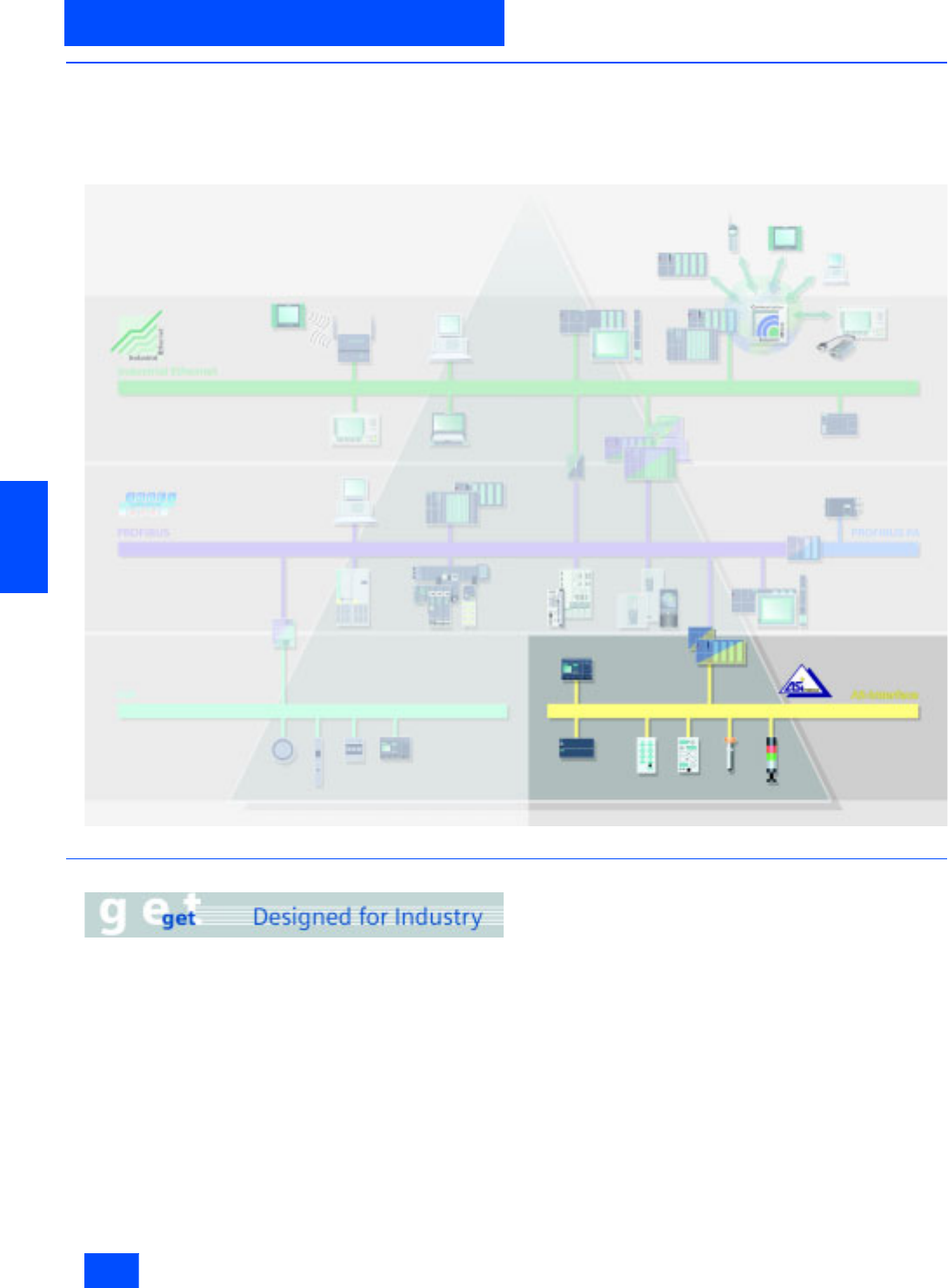
Example of a system configuration
G_IK10_XX_20027
Connection via AS-Interface cable
AS-Interface distributor
(without AS-Interface chip)
AS-Interface cable
AS-Interface
power section
Branch M12
K60
AS-Interface distributor
(without AS-Interface chip)
Repeater
LOGO!
Operator panel
K45
(with AS-Interface chip)
for connection of
standard sensors
Standard encoders
e.g. position switches
Standard sensor
e.g. inductive BERO
Compact starter IP 65
max 100 m
SONAR BERO
with int. AS-Interface
AS-Interface
power section
Siemens IK PI · 2004
6/4
AS-Interface
System components
Introduction
6
■
Overview
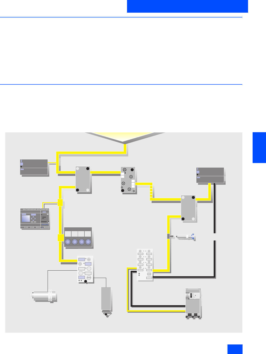
System components
Many system components are available to implement communi-
cations. The basic components of a system installation are:
• Master interfaces for central control units such as SIMATIC S5
and SIMATIC S7, distributed I/Os ET 200® M/X,
• AS-Interface shaped cables
• Network components such as repeaters/extenders
• The power supply unit for supplying power to the slaves,
modules for connecting standard sensors/actuators
• Actuators and sensors with integrated ASIC slave
• Fail-safe modules for transmission of secure data through
AS-Interface,
• Address programming device for setting the slave address.
AS-Interface master for SIMATIC
01
Integrated interface
CP 343-2
CP 243-2
CP 142-2
CP 2430
C7-621 ASi
S5-115U to 155U
ET 200M
S7-200
ET 200X
S7-300
G_IK10_XX_20009
DP/AS-Interface Link 20E
Links
CP 343-2 P

Siemens IK PI · 2004 6/5
AS-Interface
Introduction
Technical specifications
6
■
Technical specifications
■
More information
Please note the operating framework conditions in each case for
the specified SIMATIC NET products (Order No. 6GK..., 6XV1...),
which you will find on the Internet page listed below.
Additional information is available in the Internet under:
http://www.siemens.de/simatic-net/ik-info
Standard EN 50295
Topology Bus, star or tree topology
(like electrical installation)
Transmission medium Unshielded two-wire cable
(2 x 1.5 mm2) for data and
auxiliary power
Connection method Contacting of the AS-Interface
cable using the insulation
displacement method
Permissible cable length max. 100 m w/o repeater/extender
500 m range with repeater/
extender (parallel connection
of repeaters)
Cycle time max. 5 ms with full expansion,
10 ms using A/B method
Number of stations max. 31 slaves accord. to Complete
AS-Interface Spec. V2.0 ;
62 slaves accord. to Complete
AS-Interface Spec. V2.1
(A/B method),
integrated analog value
transmission
Number of binary
sensors/actuators Max. 124 I/124 O
modules according to spec. V2.0;
Max. 248 I/186 O
modules according to spec. V2.1
Access procedure Cyclical master-slave polling
method, cyclical acceptance
by host (PLC, PC)
Error correction Identification and repetition of
faulty messages
Siemens IK PI · 2004
6/6
AS-Interface
A/B technique
6
■
Overview
The A/B technique concept
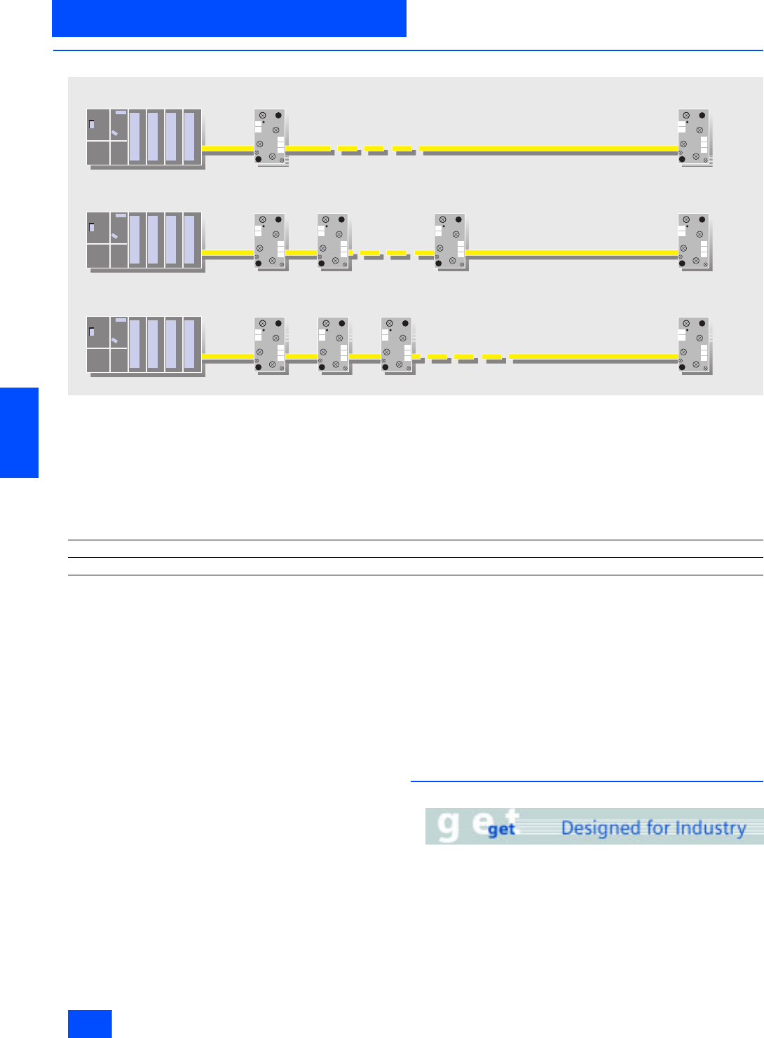
The AS-Interface specification 2.1 allows a doubling of network
stations from 31 to 62. The 31 addresses that can be assigned
in an AS-Interface network can be split into two mutually inde-
pendent sub-addresses, e.g. in 1A and 1B.
If this is utilized for all 31 slaves, up to 62 slaves can be con-
nected within an AS-Interface network. The so-called A/B slaves
can each have up to four inputs and three outputs.
Another new feature of the new AS-Interface specification V2.1
is integrated analog value transfer. In this case, integrated
means that no special function blocks are required in order to
access the analog values. Accessing data is therefore just as
easy in the case of analog values as it is with digital values. In-
tegrated analog value transfer can be used with analog slaves
that support Proifiles 7.3 and 7.4.
AS-Interface master
To operate A/B slaves in an AS-Interface network, master mod-
ules working according to the specification 2.1 must also be
used. The A/B technique is supported by the SIMATIC S7
masters and the DP/AS-Interface links from Siemens. To masters
that do not support specification 2.1, only standard and A slaves
can be connected.
The sub-address of A/B slaves is set to “A” by default.
Masters and slaves that are already working to the new specifi-
cation are identified accordingly in the catalog.
Addressing A/B slaves
A/B slaves can be addressed like standard slaves via all com-
mercial AS-Interface addressing units conforming to specifica-
tion 2.1. AS-Interface addressing units that do not conform to the
new specification 2.1 can readdress A/B slaves only as A slaves.
As far as addressing is concerned, an analog slave is like a stan-
dard slave. Up to 31 analog slaves can therefore be operated in
one AS-Interface segment.
Communication cycle
Standard slaves are polled in every cycle (max. cycle time:
5ms).
If only an A or B slave is installed at an address, this slave is also
polled in every cycle (max. cycle time: 5 ms).
If an A/B slave pair is installed at an address, slave A is polled in
one cycle, slave B in the next (max. cycle time: 10 ms).
If only standard and/or A slaves are installed in a network, the
cycle time is the same as for standard masters (max. cycle time:
5 ms).
■
Benefits
• Lower costs for masters and power supply units
• Enhanced decentralization in installations with numerous,
widely distributed signals
• Existing AS-Interface systems can be expanded further
G_IK10_XX_20020
Previously 31 nodes Slave 1
with A/B slaves max. 62 nodes:
Mixed operation also permissible:
Slave 31
Slave 1A Slave 31B
Slave 1 Slave 31
Slave 1B Slave 31A
Slave 2A Slave 2B
Slave type Number of slaves Number of inputs Number of outputs
AS-Interface standard Standard slave Up to 31 31 x 4 = 124 31 x 4 = 124
AS-Interface version 2.1 A/B slave Up to 62 62 x 4 = 248 62 x 3 = 186
Siemens IK PI · 2004 6/7
AS-Interface
A/B technique
6
■
Selection and Ordering data
1) Start of delivery: approx. end of 2003.
Design Order No.
Master according to Specification 2.1
CP 243-2
Master for SIMATIC S7-200
6GK7 243-2AX01-0XA0
CP 343-2
Master for SIMATIC S7-300
6GK7 343-2AH00-0XA0
CP 343-2 P
master for SIMATIC S7-300
configuration with STEP 7
6GK7 343-2AH10-0XA0
DP/AS-Interface Link 20E
Gateway for transition from AS-Interface to PROFIBUS DP
6GK1 415-2AA01
A/B slaves
3RK2 200-0CQ20-0AA3
K45 compact module
• 4 inputs
- M12 connection
3RK2 200-0CQ20-0AA3
- M8 screw-type connection
3RK2 200-0CT20-0AA3
- M8 snap-on connection
3RK2 200-0CU20-0AA3
•2 x 2 inputs
3RK2 200-0CQ22-0AA3
• 3 outputs
3RK2 100-1EQ20-0AA3
• 2 outputs / 2 inputs 1)
3RK2 400-1BQ20-0AA3
3RK2 400-1HQ00-0AA3
K60 compact module
• 8 inputs /2 outputs
3RK2 400-1HQ00-0AA3
• 8 inputs
3RK2 200-0DQ00-0AA3
• 4 inputs/ 3 outputs
3RK2 400-1FQ03-0AA3
3RK2 200-0CE02-0AA2
Slimline S22.5
• 4 inputs
- Screw-type terminals 1)
3RK2 200-0CE02-0AA2
- Cage Clamp terminals 1)
3RK2 200-0CG02-0AA2
3RK2 400-1FE00-0AA2
Slimline S45
• 4 inputs/ 3 outputs
- Screw terminals
3RK2 400-1FE00-0AA2
- Cage Clamp terminals
3RK2 400-1FG00-0AA2
Siemens IK PI · 2004
6/8
AS-Interface
Introduction
AS-Interface Safety at work
6
■
Overview
Safety included
The Safety at Work concept supports the direct integration of
components with relevance for safety, such as emergency stop
switches, protective cover switches or safety light barriers, in the
AS-Interface network. These are fully compatible with the familiar
AS-Interface components (masters, slaves, power supply units,
repeaters, etc.) in accordance with EN 50295 and are operated
in conjunction with them on the yellow AS-i cable.
The signals from the safety sensors are evaluated by a safety
monitor. This not only monitors the switching signals of the safety
sensors but also continuously checks that data is being trans-
ferred correctly. The safety monitor has one or two release cir-
cuits in a two-channel configuration which can be used to bring
the machine or installation into a safe state. Sensors and moni-
tors can be connected at any point on the AS-Interface network.
It is also possible to use several monitors in the same network.
A failsafe controller or a special master is not necessary. The
master handles safety slaves in the same manner as all other
slaves and only receives the safety data for information pur-
poses. They can therefore be used to expand any existing
AS-Interface network.
Safety at Work guarantees a maximum response time of 40 ms.
This is the time between application of the signal to the input of
the safe slave and switching off the output at the safety monitor.
Tested safety
The system has been tested and approved by the German
Technical Inspectorate (TÜV). The transmission technique for
signals with relevance for safety is designed to allow applica-
tions to be implemented up to category 4 in accordance with
EN 954-1.
Software
The safety-related applications can be configured using the
configuration software and then transferred into the monitor.
Moreover, the software can also be used for online diagnostics.
■
Benefits
• A failsafe PLC or special master is not required.
• Simple system structure due to standardized AS-Interface
technique.
• Safe and non-safe data on the same bus.
• Existing systems can be expanded quickly and easily.
• Safe signals can be combined in groups.
• Integration of the safety signals in the plant diagnostics con-
cept.
• Approved up to category 4 acc. to EN 954-1.
•Safety at Work is certified by the German Technical Inspec-
torate (TÜV).
■
Application
Integrated safety systems using AS-Interface can be used in ap-
plications for which EMERGENCY-STOP pushbuttons, protective
door locks, Stop category 0 and 1, two-handed operation and
light arrays are currently installed.
■
Design
The safety system is constructed in the same manner as the now
familiar installation of AS-Interface.
The family of safe AS-Interface products comprises the safety
monitor that monitors the safe stations. The spectrum of safe sta-
tions comprises the safe modules and the safety-related sensors
with an integrated interface.
■
Function
Following a master call, the safe stations transmit their informa-
tion, like the standard stations, to the master. The safety monitor
monitors this transfer from the safe stations to the master and
switches
• to the EMERGENCY-STOP status (in the case of faults in safe
stations) or
• to the safe status (in the case of a wire break).
The safety monitor is configured using software. The configura-
tion comprises the input signals of the safe stations and the in-
ternal functions of the safety monitor. The safety monitor offers
OR logic, AND logic, timer functions, buffer storage, etc.
■
Integration
For integration of the safety system into AS-Interface, the exist-
ing infrastructure such as the master and the power supply unit
can continue to be used. For the safety system, the safety mon-
itor is integrated as a monitoring component and the safe station
is integrated as the interface between the safe sensors and the
system. The safe sensors can be used as before.
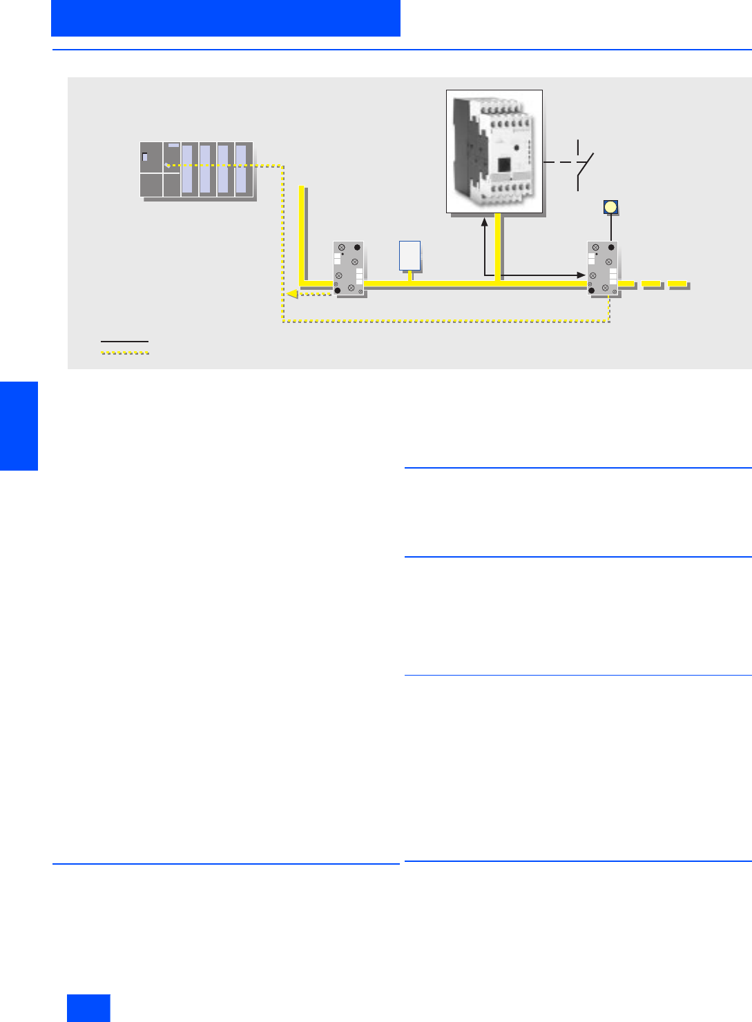
G_IK10_XX_20021
Standard PLC
Standard master
Standard slave
Security monitor
Secure slave
with EMERGENCY-OFF
Signal evaluation of secure slave/security monitor
Master information (through regular I/O transfer)
Power section
Siemens IK PI · 2004 6/9
AS-Interface
AS-Interface Safety at work
AS-Interface safety monitors
6
■
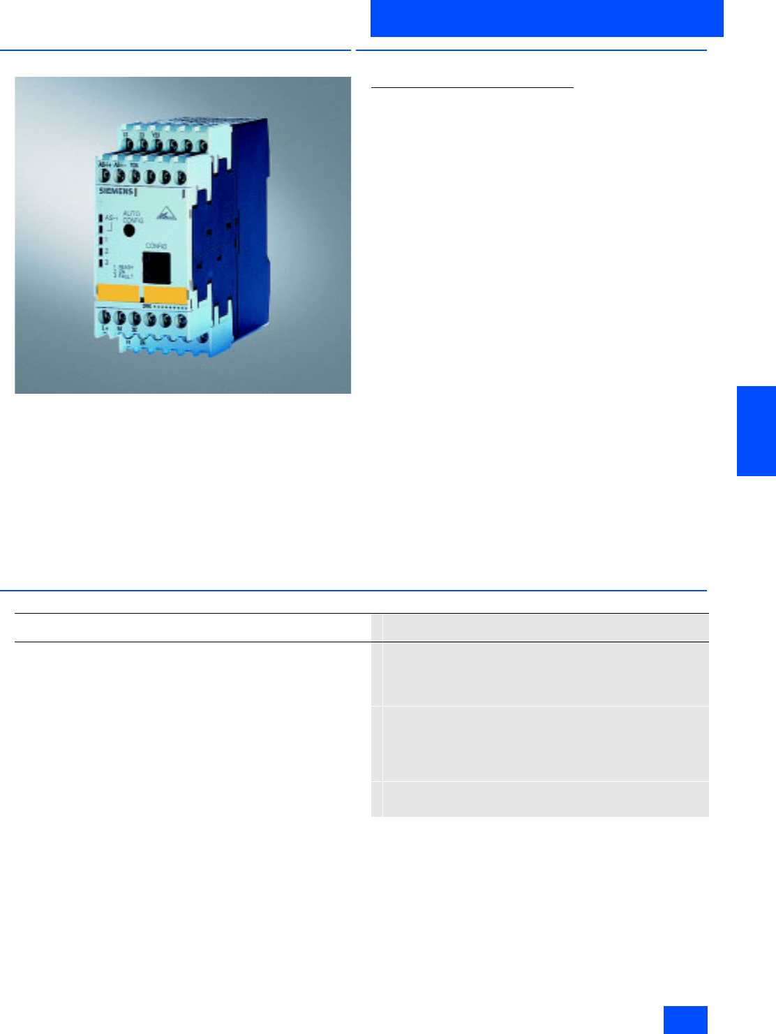
Overview
The safety monitor is the core component of Safety at Work. A
safe application is configured with a PC via the safety monitor.
Various different application-specific operating modes can be
used. These include the EMERGENCY-STOP function, tumbler,
two-handed operation as well as selection of Stop category
0 or 1.
In order to fully utilize the AS-Interface diagnostic capability, the
monitor can also be operated with AS-Interface addresses as an
alternative.
Two versions of the monitor are available:
• Safety monitor with one two-channel release circuit
• Safety monitor with two two-channel release circuits
■
Function
Safety monitor with enlarged functions
Logical OR operation
In this logical operation up to six elements can be OR gated.
(Until now, only two elements could be OR gated).
Logical AND operation
In addition to the standard AND gating in the main path of an
enabling circuit, an AND operation can be inserted into an OR
operation. More than two elements can be gated in this AND.
Buffer
Temporary shutdowns are stored in a buffer for the purpose of
diagnostics.
Number of devices
The number of devices that the safety monitor can process has
been increased from 32 to 48. Applications that are larger and
more complex can now be simulated in the safety monitor.
Timer functions
Timers are offered with the functions
• Delayed switching-on
• Delayed switching-off and
• Pulse.
Compatibility
Any configurations that have been previously created can be
loaded into the "new" safety monitor without changes.
■
Technical specifications
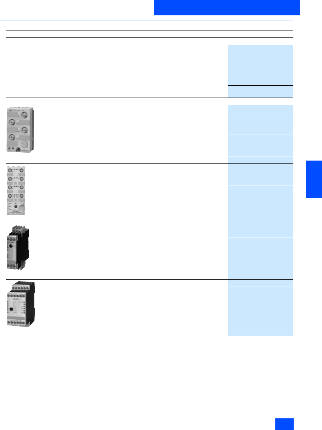
Safety monitor
3RK1 105
Rated operational current
•I
e/AC-12 up to 250 V, 2 A
•I
e/AC-15 115 V, 2A
230 V, 2A
•I
e/DC-12 up to 24 V, 3 A
•I
e/DC-13 24 V, 1 A
115 V, 0.1 A
230 V, 0.05 A
• Response time < 40 ms
• Ambient temperature in °C 0 to +60
• Storage temperature in °C -40 to +85
Siemens IK PI · 2004
6/10
AS-Interface
AS-Interface safety monitors
AS-Interface Safety at work
6
■
Selection and Ordering data
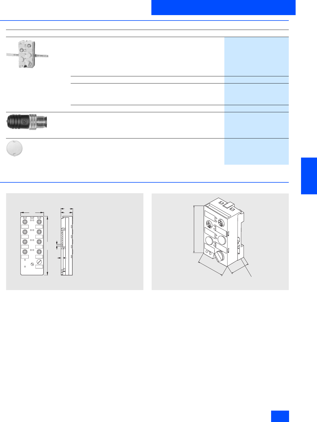
■
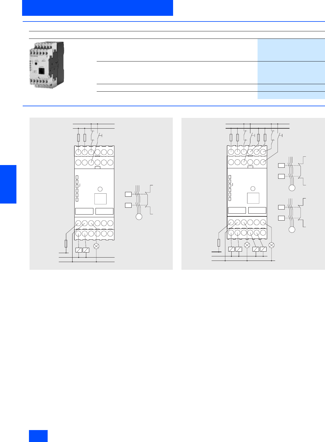
Dimensional drawings
Safety monitor with one release circuit
Safety monitor with two release circuits
Design
Order No.
Safety monitor
Safety monitor
• One enabling circuit
3RK1 105-1AE04-0CA0
• Two enabling circuits
3RK1 105-1BE04-0CA0
Safety monitor with extended functionality
• One enabling circuit
3RK1105-1AE04-2CA0
• Two enabling circuits
3RK1105-1BE04-2CA0
Configuration software
3RK1 802-2FB06-0GA0
Cable set
3RK1 901-5AA00
L/+
L
K1
K2 Start 1
1.13 1.23 1.Y1
AS-i+AS-i- 1.Y2
AS-i
1
2
3
L+ M 1.32
1.14 1.24 PE
K1 K2
L+
M/N
M
K1
K2
M
L+
1.Y1
g_nsa0_xx_00356
L/+
L
Start 2
Start 1
K1
K2
K3
K4
1.13 1.23 1.Y1
AS-i+ AS-i- 1.Y2
AS-i
1
2
3
K1
K2
L+ M 1.32 2.32
1.14 1.24 PE 2.14 2.24
K1 K2 K3 K4
L+
M/N
M
L/+
1.Y1
M
K3
K4
L/+
M2.Y1
g_nsa_xx_00357
Siemens IK PI · 2004 6/11
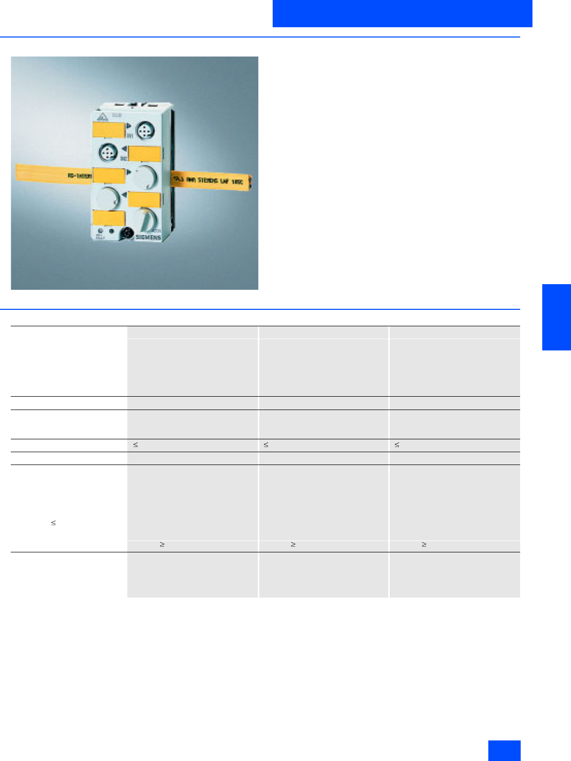
AS-Interface
AS-Interface Safety at work
AS-Interface safe compact modules
6
■
Overview
The compact module product family will be supplemented with
safe modules:
• The K45F safe compact module is equipped with two "safe" in-
puts. For operation up to category 2 acc. to EN 954-1, each in-
put can be separately assigned. If category 4 is required, a
two-channel input is available on the module.
• The K60F safe compact module has, in addition to the two safe
inputs, also two standard outputs.
■
Technical specifications
K45F safe compact module K60F safe compact module K60F safe compact module
PNP transistor PNP transistor PNP transistor
Standard assignment Standard assignment Standard assignment
2 safe inputs 2 safe inputs,
2 standard outputs
2 safe inputs,
2 standard outputs with UAux
3RK1 205-0BQ00-0AA3 3RK1 405-0BQ00-0AA3 3RK1 405-0BQ00-0AA3
AS-Interface chip SAP 4 SAP 4 SAP 4
Operational voltage
in accordance with AS-Interface
specification in V
26.5 to 31.5 26.5 to 31.5 26.5 to 31.5
Total current input in mA 45 270 270
Input connection PNP PNP PNP
Inputs
• Sensor supply via AS-Interface -- -- --
•Sensors Mechanical switching contact Mechanical switching contact Mechanical switching contact
• Voltage range in V -- -- --
• Current carrying capacity for all
inputs (Tu40 °C) in mA -- -- --
• Switching level High in V Contact open/closed Contact open/closed Contact open/closed
• Input current Low/High in mA - / /peak 5 - / /peak 5 - / /peak 5
Pin assignment inputs Pin1 and 2 = Terminal/switching
contact
Pin3 and 4
Terminal/switching contact
Pin5 = Not assigned
Pin1 and 2 = Terminal/switching
contact
Pin3 and 4
Terminal/switching contact
Pin5 = Not assigned
Pin1 and 2 = Terminal/switching
contact
Pin3 and 4
Terminal/switching contact
Pin5 = Not assigned

Siemens IK PI · 2004
6/12
AS-Interface
AS-Interface safe compact modules
AS-Interface Safety at work
6
■
Technical specifications (continued)
Outputs
• Type of output -- Electronics Electronics
• Current carrying capacity
DC 12/13 in A -- 2--
• Current carrying capacity typ.
(max. 4 A per module) in A -- Max. 0.18 Max. 4
• Pin assignment outputs -- 3 = "–"
4 = Output
5 = Earth connection
3 = "–"
4 = Output
5 = Earth connection
• Short-circuit protection -- Built-in Built-in
• Inductive interference protec-
tion (free-wheeling diode) -- None Built-in
• External voltage supply
24 V DC -- -- Via black AS-Interface flat cable
• Watchdog -- Built-in Built-in
I/O configuration 077
ID/ID2 code BBB
Assignment of data bits
• Socket 3 and 4 Not assigned (closed) Not assigned (closed) Not assigned (closed)
• Socket 5 Not assigned (closed) Pin 4 = OUT1 (D0)
Pin 2 = Not assigned (closed) Pin 4 = OUT1 (D0)
Pin 2 = Not assigned (closed)
• Socket 6 Not assigned (closed) Pin 4 = OUT2 (D1)
Pin 2 = Not assigned (closed) Pin 4 = OUT2 (D1)
Pin 2 = Not assigned (closed)
• Socket 7 and 8 Not assigned (closed) Not assigned (closed) Not assigned (closed)
AS-Interface certificate Yes Yes Yes
Approvals UL, CSA UL, CSA UL, CSA
Degree of protection IP67 IP67 IP67
Earth connection -- PIN 5 of each M 12 socket is
connected to the grounding plate in
the mounting plate via a pin
(outputs only sockets 5 and 6).
PIN 5 of each M 12 socket is
connected to the grounding plate in
the mounting plate via a pin
(outputs only sockets 5 and 6).
Ambient temperature in °C -25 to +85 -25 to +85 -25 to +85
Storage temperature in °C -40 to +85 -40 to +85 -40 to +85
Number of I/O sockets 244
Status indication
• I/O display Yellow LED Yellow LED Yellow LED
•UAux -- -- Green LED
• AS-Interface/diagnostics
display Green/red LED Green/red LED Green/red LED
Connection via mounting plate for K45 compact
module via mounting plate for K60 compact
module via mounting plate for K60 compact
module
Addressing Front addressing socket,
after the 15th addressing,
the module keeps the last address
Front addressing socket,
after the 15th addressing,
the module keeps the last address
Front addressing socket,
after the 15th addressing,
the module keeps the last address
Siemens IK PI · 2004 6/13
AS-Interface
AS-Interface Safety at work
AS-Interface safe compact modules
6
■
Selection and Ordering data
1) Modules supplied without mounting plate.
■
Dimensional drawings
K60F safe module
K45F safe module
Design
Order No.
3RK1 205-0BQ00-0AA3
K45F safe compact module 1)
2FE
3RK1 205-0BQ00-0AA3
K45 mounting plate
3RK1 901-2EA00
K60F safe compact module 1)
• 2FE/2A
3RK1 405-0BQ00-0AA3
• 2FE/2A with UAux
3RK1 405-1BQ00-0AA3
K60 mounting plate
3RK1 901-0CA00
3RK1 901-1AA00
Input bridge for K45/K60F
• Black version
3RK1 901-1AA00
• Red version
3RK1 901-1AA01
3RK1 901-1KA01
AS-Interface M12 sealing caps, protected against manipulation
For spare M12 sockets
(one packing contains ten sealing caps)
3RK1 901-1KA01
N S A 0 _ 0 0 0 2 6
Æ
4 , 5
3 1
2 9
5
1 5 2
6 0
S i d e v i e w w i t h
m o u n t i n g p l a t e
3 R K 1 9 0 1 - 0 C A 0 0
45
80
30
Mounting plate
3RK1901-2EA00
Siemens IK PI · 2004
6/14
AS-Interface
AS-Interface safe compact modules
AS-Interface Safety at work
6
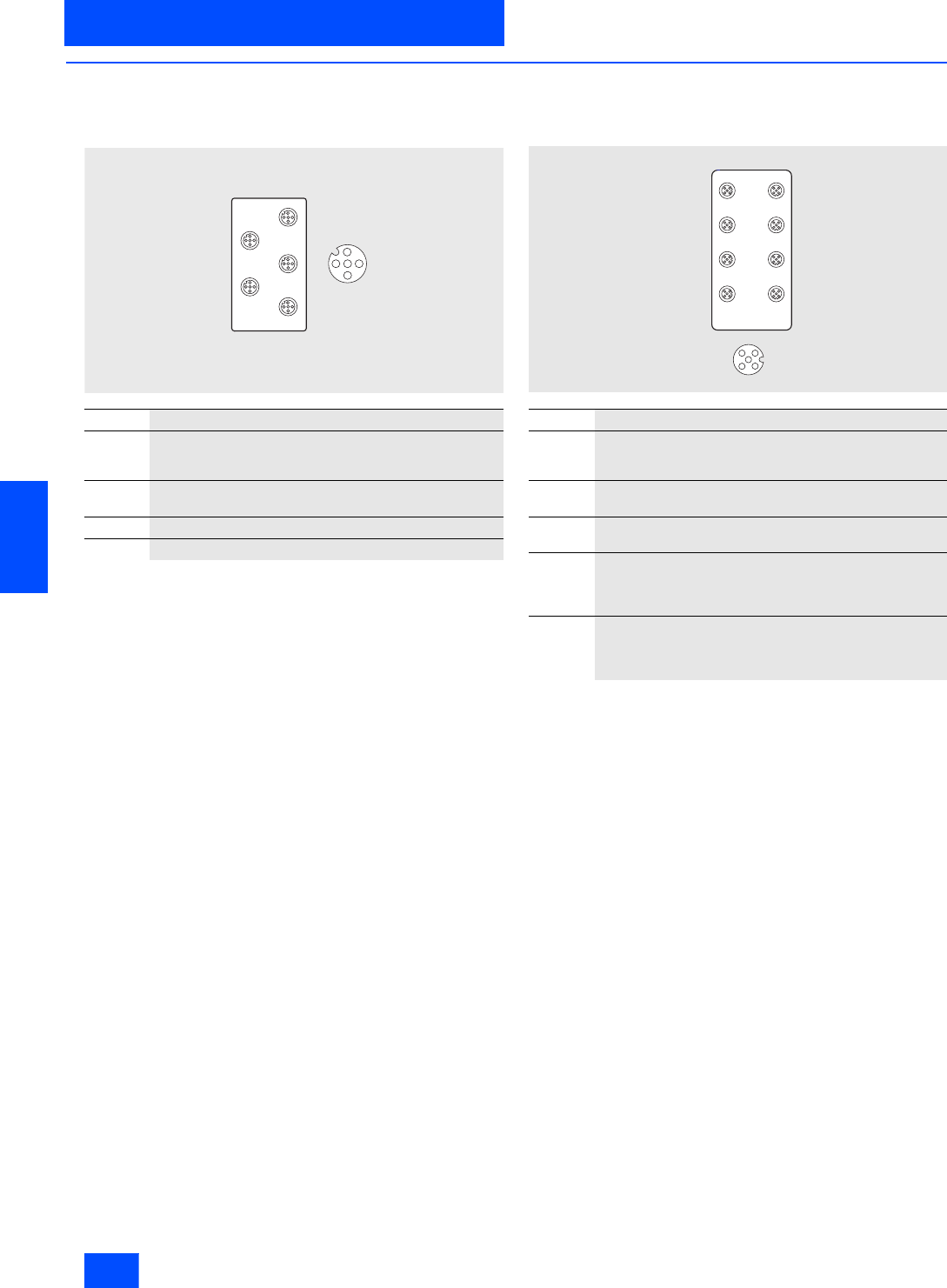
■
Schematics
Logical assignments
K45F Safe Compact Module
If only one single-channel switch will be connected to the mod-
ule, this must be connected to Channel 1. The second channel
must be bridged. This can be performed with the M12 connector
3RK1901-1AA00 on Socket 2.
Pin 3 of Socket 1 is connected to Pin 1 of Socket 2 and Pin 4 of
Socket 1 is connected to Pin 2 of Socket 2. If both socket pairs
are assigned, the inputs are linked.
K60F Safe Compact Module
Pin 3 of Socket 1 is connected to Pin 1 of Socket 2 and Pin 4 of
Socket 1 is connected to Pin 2 of Socket 2. If both socket pairs
are assigned, the inputs are linked.
Socket Assignment / data sheet / function
1Pin 1 and Pin 2: affects bits D0 and D1 = Channel 1
Pin 3 and Pin 4: affects bits D2 and D3 = Channel 2
Pin 5 not assigned
2Pin 1 and Pin 2: affects bits D2 and D3 = Channel 2
Pin 5 not assigned
3Unused
4Unused
²
1
2
3
4
ADDR
1
2
3
4
G_NSA0_XX_00355
Socket Assignment / data sheet / function
1Pin1 and Pin 2: affects bits D0 and D1 = Channel 1
Pin 3 and Pin 4: affects bits D2 and D3 = Channel 2
Pin 5: unused
2Pin 1 and Pin 2: affects bits D2 and D3 = Channel 2
Pin 5: unused
3/4/7 and
8Not assigned, factory sealed
5Pin 4: Output 1
Pin 3: --
Pin 5: Ground
Pin 1 and Pin 2: unused
6Pin 4: Output 2
Pin 3: --
Pin 5: Ground
Pin 1 and Pin 2: unused
3
4
2N S A _ 0 0 3 5 8
1
3
7
5
1
4
8
6
2
Siemens IK PI · 2004 6/15
AS-Interface
AS-Interface Safety at work
AS-Interface position switches
6
■
Overview
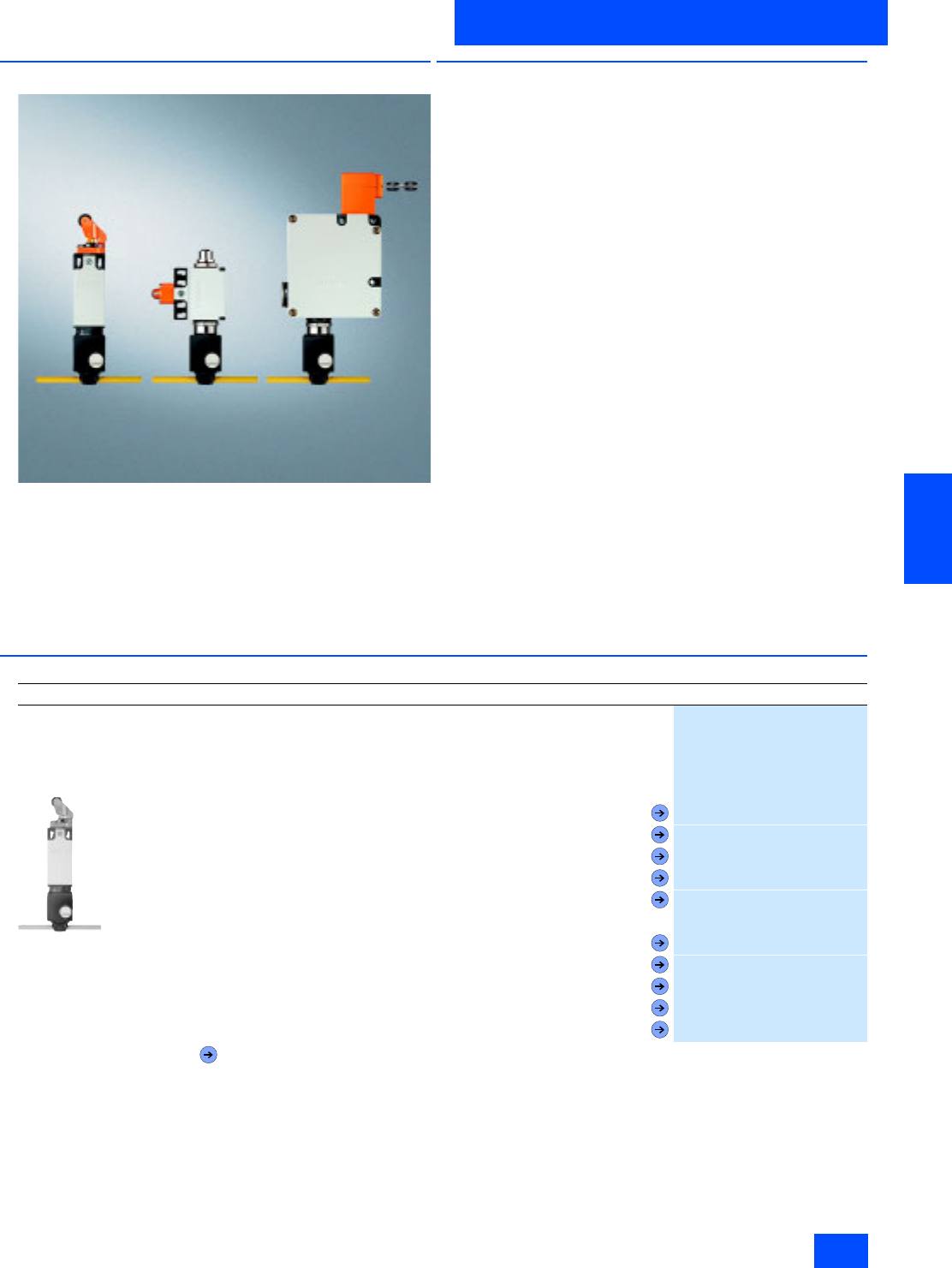
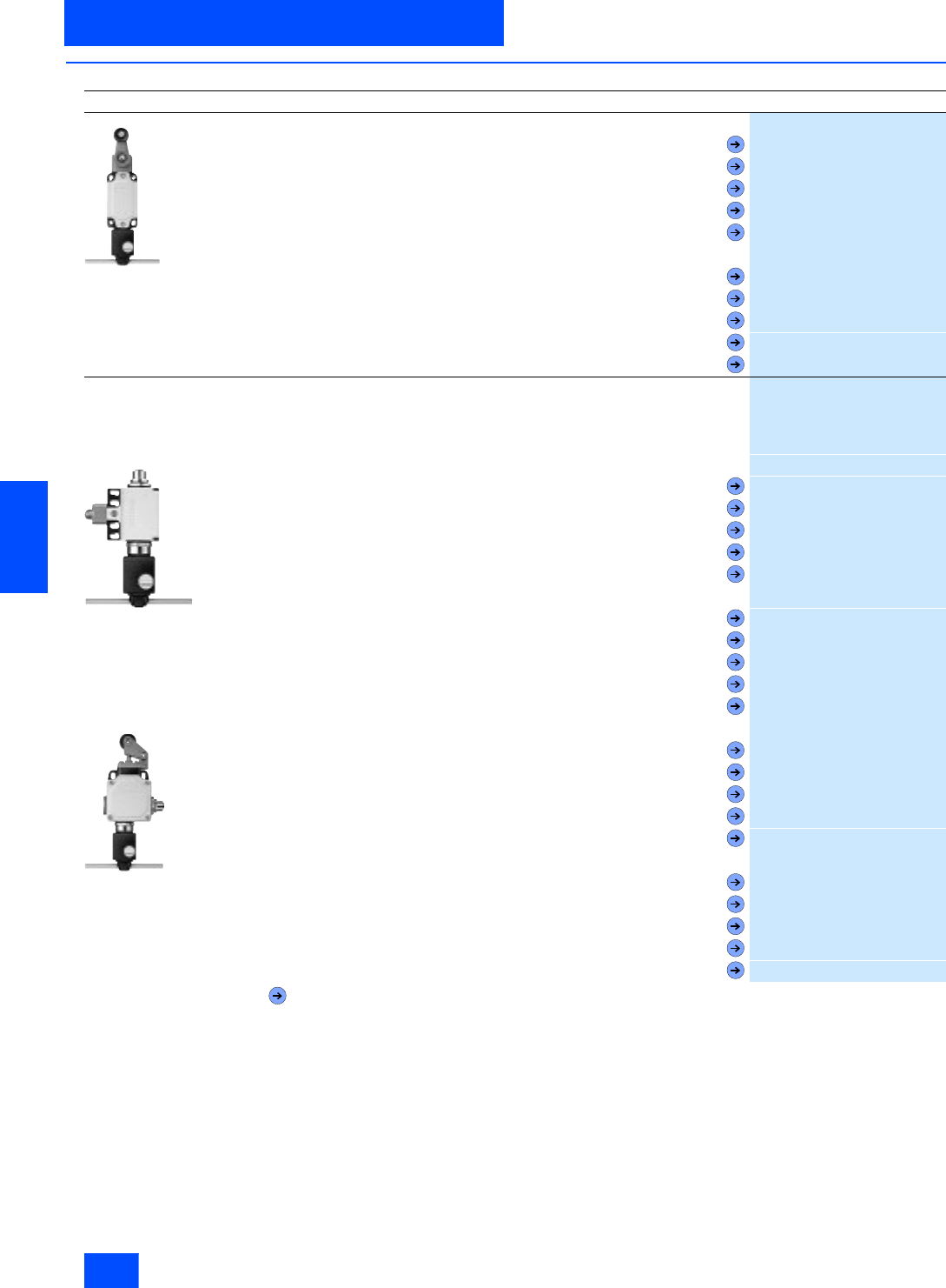
Position switch from left to right:
Standard / Standard, with M12 connector / with tumbler
It is also possible now to directly connect SIGUARD position
switches via the standard AS-Interface with safety-oriented com-
munication. In this case, the safety functions no longer have to
be conventionally wired up.
Position switches convert the mechanical positions of moving
machine components into electrical signals.
■
Application
Position switch with separate actuator
The position switches with separate actuator are used in appli-
cations in which the position of doors, covers or guards has to
be monitored for safety reasons.
The position switch can only be switched using the associated
coded actuator. It is not possible to bypass it manually or using
a tool.
Position switch with tumbler
The position switches with tumblers are special safety devices
that prevent the inadvertent or intentional opening of protective
doors, guards or other covers when a dangerous state exists,
e.g. for coastdown movements of the switched-off machine.
The safety switch with tumbler has two main tasks:
• Enabling the machine when the protective device is closed
and locked
• Disabling the machine when the protective device is open
The position switch can only be switched using the associated
coded actuator. It is not possible to bypass it manually or using
a tool.
■
Selection and Ordering data
Design
Order No.
AS-Interface position switch, standard
Via AS-Interface F adaptor
With direct connection of AS-Interface to Safety at Work
For use up to Category 2 acc. to EN 954-1
IP65
3SF3 200-6EV00-0BA1
•Molded plastic enclosure, EN 50 047, 31 mm wide, slow-action contact, two NC
- Overtravel plunger
3SF3 200-6CV00-0BA1
- Roller plunger
3SF3 200-6DV00-0BA1
- Roller lever
3SF3 200-6EV00-0BA1
- Angular roller lever
3SF3 200-6FV00-0BA1
- Swivel lever
3SF3 200-6GV00-0BA1
•Molded plastic enclosure, EN 50 047, 31 mm wide, snap action contact, one NC
- Overtravel plunger
3SF3 200-1CV00-0BA1
- Roller plunger
3SF3 200-1DV00-0BA1
- Roller lever
3SF3 200-1EV00-0BA1
- Angular roller lever
3SF3 200-1FV00-0BA1
- Swivel lever
3SF3 200-1GV00-0BA1
Forced opening IEC 60 947-5-1, Appendix K.
Siemens IK PI · 2004
6/16
AS-Interface
AS-Interface position switches
AS-Interface Safety at work
6
■
Selection and Ordering data (continued)
Design
Order No.
3SF3 120-6GW00-0BA1
•Metal enclosure, EN 50 041, 40 mm wide, slow-action contact, two NC
- Overtravel plunger
3SF3 120-6CV00-0BA1
- Roller plunger
3SF3 120-6DV00-0BA1
- Roller lever
3SF3 120-6EV00-0BA1
- Angular roller lever
3SF3 120-6FV00-0BA1
- Swivel lever
3SF3 120-6GW00-0BA1
•Metal enclosure, EN 50 041, 40 mm wide, snap action contact, one NC
- Overtravel plunger
3SF3 120-1CV00-0BA1
- Roller plunger
3SF3 120-1DV00-0BA1
- Roller lever
3SF3 120-1EV00-0BA1
- Angular roller lever
3SF3 120-1FV00-0BA1
- Swivel lever
3SF3 120-1GW00-0BA1
AS-Interface position switch, standard, with M12 connector
M12 connector for connecting an additional position switch
Direct connection of AS-Interface to Safety at Work
For use up to Category 4 acc. to EN 954-1
IP65
3SF3 210-0DV00-0BA2
•Molded plastic enclosure, EN 50 047, 50 mm wide, slow-action contact, 1 NC
- Overtravel plunger
3SF3 210-0CV00-0BA2
- Roller plunger
3SF3 210-0DV00-0BA2
- Roller lever
3SF3 210-0EV00-0BA2
- Angular roller lever
3SF3 210-0FV00-0BA2
- Swivel lever
3SF3 210-0GV00-0BA2
•Molded plastic enclosure, EN 50 047, 50 mm wide, snap-action contact, 1 NC
- Overtravel plunger
3SF3 210-1CV00-0BA2
- Roller plunger
3SF3 210-1DV00-0BA2
- Roller lever
3SF3 210-1EV00-0BA2
- Angular roller lever
3SF3 210-1FV00-0BA2
- Swivel lever
3SF3 210-1GV00-0BA2
3SF3 100-0EV00-0BA2
•Metal enclosure, EN 50 041, 56 mm wide, slow-action contact, 1 NC
- Overtravel plunger
3SF3 100-0CV00-0BA2
- Roller plunger
3SF3 100-0DV00-0BA2
- Roller lever
3SF3 100-0EV00-0BA2
- Angular roller lever
3SF3 100-0FV00-0BA2
- Swivel lever
3SF3 100-0GW00-0BA2
•Metal enclosure, EN 50 041, 56 mm wide, snap-action contact, 1 NC
- Overtravel plunger
3SF3 100-1CV00-0BA2
- Roller plunger
3SF3 100-1DV00-0BA2
- Roller lever
3SF3 100-1EV00-0BA2
- Angular roller lever
3SF3 100-1FV00-0BA2
- Swivel lever
3SF3 100-1GW00-0BA2
Forced opening IEC 60 947-5-1, Appendix K.

Siemens IK PI · 2004 6/17
AS-Interface
AS-Interface Safety at work
AS-Interface position switches
6
■
Selection and Ordering data (continued)
1) 1) Accessories, technical data, contact travel, circuit diagrams and
dimensional drawings for the specified basic switch can be found in
the Catalog LV 10, Edition 2004, Section AS-Interface Safety Systems.
Design
Order No.
AS-Interface position switch, with separate actuator
With direct connection of AS-Interface to Safety at Work
For use up to Category 2 acc. to EN 954-1
IP65, Slow-action contact, 2 NC
•Molded plastic enclosure, side operation, fixing acc. to EN 50 047
3SF3 200-6XX03-0BA1
•Molded plastic enclosure, front operation, fixing acc. to EN 50 047
3SF3 200-6XX04-0BA1
•Molded plastic enclosure, side and front operation, 52 mm wide
- 30 N extraction force
3SF3 243-0XX00-0BA1
- 5 N extraction force
3SF3 243-0XX40-0BA1
- Automatic ejection
3SF3 243-0XX30-0BA1
•Metal enclosure, fixing acc. to EN 50 041
3SF3 120-6XX00-0BA1
Actuator
• Standard, Width/length of enclosure 79 mm
3SX3 197
• With crosswise fixing, Width/length of enclosure 50 mm
3SX3 206
• Universal radius, Width/length of enclosure 80 mm
3SX3 203
3SF3 257-6XX00-0BA2
AS-Interface position switch with separate actuator and M12 connector
M12 connector for connecting an additional position switch
Direct connection of AS-Interface to Safety at Work
For use up to Category 4 acc. to EN 954-1
IP65, Slow-action contact, one NC
Molded plastic enclosure
Side and front operation
52 mm wide
• 30 N extraction force
3SF3 257-6XX00-0BA2
• 5 N extraction force
3SF3 257-6XX40-0BA2
• Automatic ejection
3SF3 257-6XX30-0BA2
Actuator
• Standard, Width/length of enclosure 27 mm
(rmin = 150 mm)
3SX3 218
• Universal radius, Width/length of enclosure 33 mm
(rmin = 45 mm)
3SX3 228
3SF3 750-6XX00-0BA1
AS-Interface position switch, with separate actuator and tumbler
With direct connection of AS-Interface to Safety at Work
For use up to Category 4 acc. to EN 954-1
IP65, Pg 13.5, Solenoid voltage 24 V DC
Monitoring of actuator and solenoid position
•Plastic housing
- Locking force 1200 N, locked by spring force
3SF3 760-6XX00-0BA1
- Locking force 1200 N, locked by magnetic force
3SF3 750-6XX00-0BA1
Actuator
•Standard,
3SX3 252
• with crosswise fixing
3SX3 253
•radius
3SX3 254
3SF3 830-6XX00-0BA1
•Metal housing
- Locking force 1200 N, locked by spring force
3SF3 860-6XX00-0BA1
- Locking force 1200 N, locked by magnetic force
3SF3 850-6XX00-0BA1
- Locking force 2000 N, locked by spring force
3SF3 840-6XX00-0BA1
- Locking force 2000 N, locked by magnetic force
3SF3 830-6XX00-0BA1
Actuator
• Standard, length 79 mm
3SX3 197
- for left approach direction, length 132 mm
3SX3 207
- with crosswise fixing, length 50 mm
3SX3 206
• Universal radius, length 80 mm
3SX3 203
Forced opening IEC 60 947-5-1, Appendix K.
Siemens IK PI · 2004
6/18
AS-Interface
AS-Interface cable-operated switches
AS-Interface Safety at work
6
■
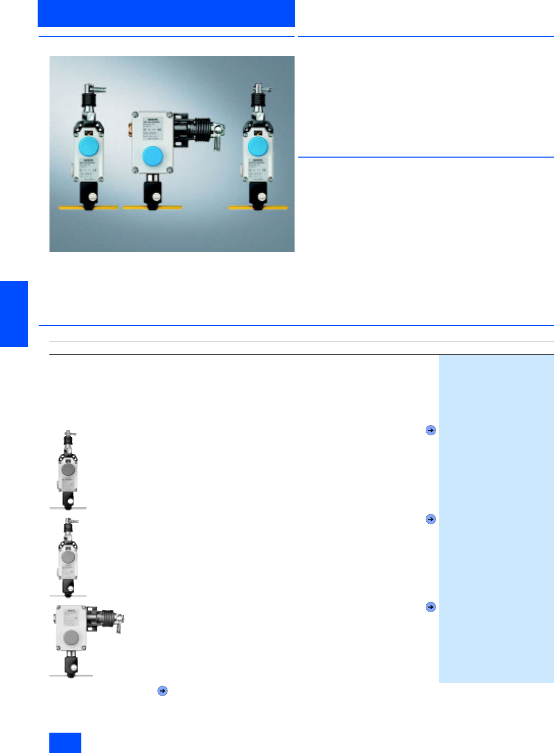
Overview
It is also possible to connect AS-Interface cable-operated
switches via the standard AS-Interface with safety-oriented com-
munication.
In this case, the safety functions no longer have to be conven-
tionally wired up.
■
Application
SIGUARD cable-operated switches are used for monitoring or
for EMERGENCY-STOP facilities on particulary endangered sys-
tem sections.
As the effective range of a cable-operated switch is limited by
the length of the cord, large systems can also be protected.
Specifications
Switches with latching for implementation in EMERGENCY-STOP
equipment correspond to the EN 418 standard.
■
Function
The safety contacts of the AS-Interface cable-operated switch
are positively driven.
The AS-Interface cable-operated switches are ready to operate
after pretensioning of the pull-wire or the rope.
When the rope is pretensioned, it must be released before the
cable-operated switch can be returned to the original state.
■
Selection and Ordering data
1) Accessories, technical specifications, contact travel, circuit diagrams
and dimensional drawings are given for the specified basic switch in
Catalog LV 10 Section AS-Interface Safety Systems
Design
Order No.
AS-Interface cable-operated switch
With direct connection of AS-Interface to Safety at Work
Metal housing with dust protection
Implementable up to Category 4 to EN 954-1
IP65
Latching to EN 418
Pushbutton release
2 NC contacts
• For cable lengths up to 10 m,
with adjustment window
3SF2 120-1BF00-0BA1
• For cable lengths up to 25 m,
with adjustment window
3SF2 150-1BF00-0BA1
• For cable lengths up to 50 m
3SF2 140-1BF00-0BA1
Forced opening IEC 60 947-5-1, Appendix K.
Siemens IK PI · 2004 6/19
AS-Interface
AS-Interface Safety at work
AS-Interface light curtains and light arrays
for Category 4
6
■
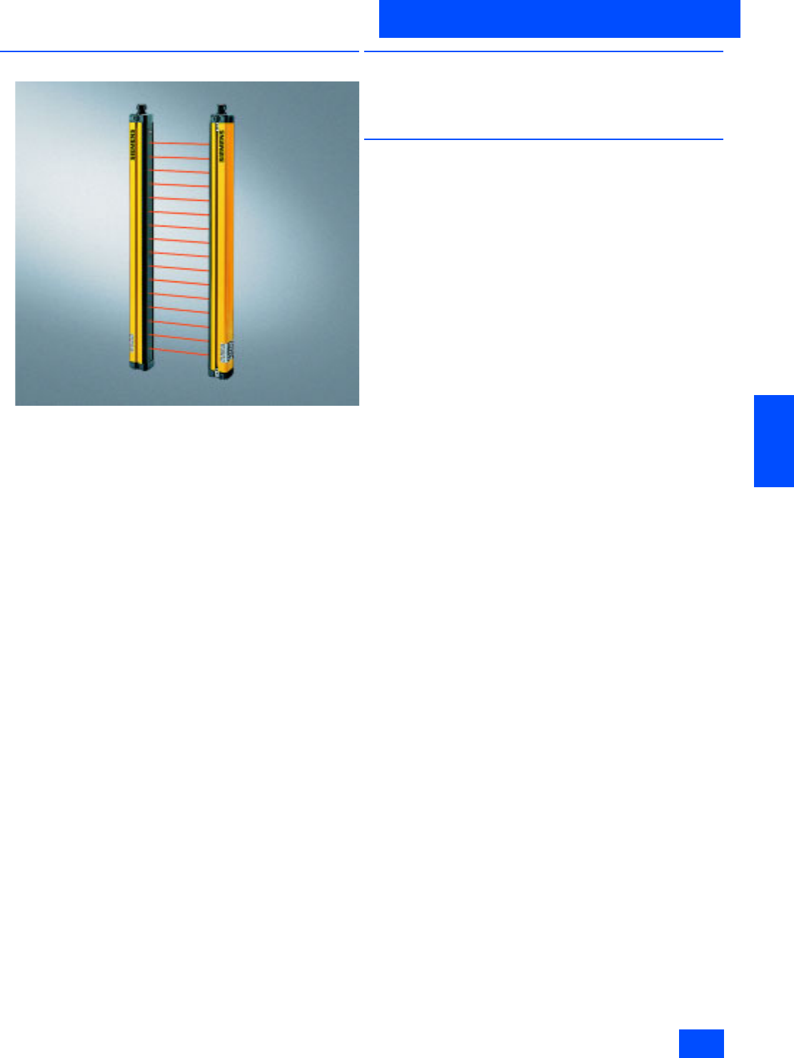
Overview
The light curtains and light arrays of Category 4 acc. to EN 954-
1 offer active optical protection for persons at machines. They
can be connected to AS-Interface directly and safely as an op-
tion.
SIGUARD light curtains and light arrays are
• active opto-electronic protective devices (AOPD),
• comply with Type 4 acc. to EN 61496-1, -2,
• are EU prototype-tested,
• protect the operating personel working on or near dangerous
machines,
• operate contact-free,
• are free of wear in comparison to mechanical systems (e.g.
safety mats).
For further details, see the manual "Safety Integrated“ and the
operating instructions for the respective devices.
■
Benefits
• Double-scan function
• Cascading of host and guest devices
• Two transmission channels
■
Design
A SIGUARD Light Curtain or light array comprises a transmitter
and a receiver that must be mounted opposite each other.
Depending on the resolution and length, a specific number of
transmit and receive diodes are arranged in a vertical row.
The infra-red LEDs of the transmitter send short light pulses that
are received by the receive diodes.
SIGUARD Light Curtains:
• Resolution 14, 30 and 50 mm,
• Length 150 mm to 3 m,
• Cascading of master and slave devices to create larger height
or length of protective zone or for angular arrangement.
SIGUARD Light Arrays:
• 2-, 3- or 4-beam for access protection.
Standards
• EN 61 496-1, -2, IEC 61 496-1, -2 (requirements for non-contact
protection systems)
• EN 999 (incl. calculation of safety clearances)
• EN 954-1 (safety of machines, safety-related parts of controls).

Siemens IK PI · 2004
6/20
AS-Interface
AS-Interface light curtains and light arrays
for Category 4
AS-Interface Safety at work
6
■
Technical specifications
1) From interruption of the protective zone to the cut-out command on AS-Interface
Technical specifications common to all AS-Interface light curtains and light arrays
Safety classification Type 4 according to IEC 61496-1, -2 or EN 61496-1 (self-monitoring)
Height of protective zone in mm 150 to 1800 (for series with 14 and 30 mm resolution)
450 to 3000 (for series with 50 mm resolution)
750 to 3000 (for series with 90 mm resolution)
Width of protective zone,
sensing range in m 0.3 to 6 (for series with 14 mm resolution)
0.8 to 18 (for series with 30, 50 and 90 mm resolution as well as for light arrays)
0.6 to 60 (for light arrays)
Detection capability 14 mm, 30 mm, 50 mm or 90 mm or complete persons with 2, 3 or 4 beams
Response time of the
safety equipment in ms 1) 12 to 44, d-scan 15 to 83 (for 14 mm resolution)
12 to 25, d-scan 15 to 44 (for 30 mm resolution)
< 22, d-scan 38 (for 50 mm resolution)
< 18, d-scan 25 (for 90 mm resolution)
Response time of the
complete system Response time 3SF7842 + response time of AS-Interface safety monitor (max. 40 ms)
Degree of protection IP65
Supply current in mA Max. 130 (transmitter)
Max 140 (receiver)
Operating mode Protection mode without restart lockout
Transmitter/receiver synchronization Optical synchronization, two transmission channels can be selected
Infra-red disturbance suppression Two techniques for selection:
Standard = high suppression
d-scan = extremely high degree of suppression
Cross-section in mm 55 * 52
Length in mm 234 to 3084 (depending on height of protective zone)
Air humidity in % 15 to 95
Operating temperature in °C 0 to +55
Storage temperature in °C -25 to +70
Supply voltage in V 26.5 to 31.6 (according to AS-Interface specification)
ID-code receiver B
I/O-code receiver 0 (four data bits as outputs)
Slave address receiver Active bus component, programmed by the user in the range 1 to 31
(delivery status = bus address 0), supply voltage from the AS-Interface network
Slave address transmitter Passive bus component (no bus address), supply voltage from the AS-Interface network
Cycle time in ms 5 (according to AS-Interface specification)
AS-Interface profile Safe slave
Electrical connection M 12 plug:
Pin 1 = ASI+
Pin 3 = ASI-
Siemens IK PI · 2004 6/21
AS-Interface
AS-Interface Safety at work
AS-Interface light curtains and light arrays
for Category 4
6
■
Selection and Ordering data
Design
Order No.
SIGUARD Standard Light Curtain, 14 mm resolution
Type 4 acc. to IEC 61 496-1, -2
Height of light curtain in mm Function
150 Transmitter
3SF7 842-6BB00
150 Receiver
3SF7 842-6BB01
225 Transmitter
3SF7 842-6BC00
225 Receiver
3SF7 842-6BC01
300 Transmitter
3SF7 842-6BD00
300 Receiver
3SF7 842-6BD01
450 Transmitter
3SF7 842-6BE00
450 Receiver
3SF7 842-6BE01
600 Transmitter
3SF7 842-6BF00
600 Receiver
3SF7 842-6BF01
750 Transmitter
3SF7 842-6BG00
750 Receiver
3SF7 842-6BG01
900 Transmitter
3SF7 842-6BH00
900 Receiver
3SF7 842-6BH01
1050 Transmitter
3SF7 842-6BJ00
1050 Receiver
3SF7 842-6BJ01
1200 Transmitter
3SF7 842-6BK00
1200 Receiver
3SF7 842-6BK01
1350 Transmitter
3SF7 842-6BL00
1350 Receiver
3SF7 842-6BL01
1500 Transmitter
3SF7 842-6BM00
1500 Receiver
3SF7 842-6BM01
1650 Transmitter
3SF7 842-6BN00
1650 Receiver
3SF7 842-6BN01
1800 Transmitter
3SF7 842-6BP00
1800 Receiver
3SF7 842-6BP01
SIGUARD Standard Light Curtain, 30 mm resolution
Type 4 acc. to IEC 61 496-1, -2
150 Transmitter
3SF7 842-6DB00
150 Receiver
3SF7 842-6DB01
225 Transmitter
3SF7 842-6DC00
225 Receiver
3SF7 842-6DC01
300 Transmitter
3SF7 842-6DD00
300 Receiver
3SF7 842-6DD01
450 Transmitter
3SF7 842-6DE00
450 Receiver
3SF7 842-6DE01
600 Transmitter
3SF7 842-6DF00
600 Receiver
3SF7 842-6DF01
750 Transmitter
3SF7 842-6DG00
750 Receiver
3SF7 842-6DG01
900 Transmitter
3SF7 842-6DH00
900 Receiver
3SF7 842-6DH01
1050 Transmitter
3SF7 842-6DJ00
1050 Receiver
3SF7 842-6DJ01
1200 Transmitter
3SF7 842-6DK00
1200 Receiver
3SF7 842-6DK01
1350 Transmitter
3SF7 842-6DL00
1350 Receiver
3SF7 842-6DL01
1500 Transmitter
3SF7 842-6DM00
1500 Receiver
3SF7 842-6DM01
1650 Transmitter
3SF7 842-6DN00
1650 Receiver
3SF7 842-6DN01
1800 Transmitter
3SF7 842-6DP00
1800 Receiver
3SF7 842-6DP01

Siemens IK PI · 2004
6/22
AS-Interface
AS-Interface light curtains and light arrays
for Category 4
AS-Interface Safety at work
6
■
Selection and Ordering data (continued)
Design
Order No.
SIGUARD Standard Light Curtain, 50 mm resolution
Type 4 acc. to IEC 61 496-1, -2
Height of light curtain in mm Function
450 Transmitter
3SF7 842-6EE00
450 Receiver
3SF7 842-6EE01
600 Transmitter
3SF7 842-6EF00
600 Receiver
3SF7 842-6EF01
750 Transmitter
3SF7 842-6EG00
750 Receiver
3SF7 842-6EG01
900 Transmitter
3SF7 842-6EH00
900 Receiver
3SF7 842-6EH01
1050 Transmitter
3SF7 842-6EJ00
1050 Receiver
3SF7 842-6EJ01
1200 Transmitter
3SF7 842-6EK00
1200 Receiver
3SF7 842-6EK01
1350 Transmitter
3SF7 842-6EL00
1350 Receiver
3SF7 842-6EL01
1500 Transmitter
3SF7 842-6EM00
1500 Receiver
3SF7 842-6EM01
1650 Transmitter
3SF7 842-6EN00
1650 Receiver
3SF7 842-6EN01
1800 Transmitter
3SF7 842-6EP00
1800 Receiver
3SF7 842-6EP01
2100 Transmitter
3SF7 842-6ER00
2100 Receiver
3SF7 842-6ER01
2400 Transmitter
3SF7 842-6ES00
2400 Receiver
3SF7 842-6ES01
2700 Transmitter
3SF7 842-6ET00
2700 Receiver
3SF7 842-6ET01
3000 Transmitter
3SF7 842-6EU00
3000 Receiver
3SF7 842-6EU01
SIGUARD Standard Light Curtain, 90 mm resolution
Type 4 acc. to IEC 61 496-1, -2
750 Transmitter
3SF7 842-6JG00
750 Receiver
3SF7 842-6JG01
900 Transmitter
3SF7 842-6JH00
900 Receiver
3SF7 842-6JH01
1050 Transmitter
3SF7 842-6JJ00
1050 Receiver
3SF7 842-6JJ01
1200 Transmitter
3SF7 842-6JK00
1200 Receiver
3SF7 842-6JK01
1350 Transmitter
3SF7 842-6JL00
1350 Receiver
3SF7 842-6JL01
1500 Transmitter
3SF7 842-6JM00
1500 Receiver
3SF7 842-6JM01
1650 Transmitter
3SF7 842-6JN00
1650 Receiver
3SF7 842-6JN01
1800 Transmitter
3SF7 842-6JP00
1800 Receiver
3SF7 842-6JP01
2100 Transmitter
3SF7 842-6JR00
2100 Receiver
3SF7 842-6JR01
2400 Transmitter
3SF7 842-6JS00
2400 Receiver
3SF7 842-6JS01
2700 Transmitter
3SF7 842-6JT00
2700 Receiver
3SF7 842-6JT01
3000 Transmitter
3SF7 842-6JU00
3000 Receiver
3SF7 842-6JU01

Siemens IK PI · 2004 6/23
AS-Interface
AS-Interface Safety at work
AS-Interface light curtains and light arrays
for Category 4
6
■
Selection and Ordering data (continued)
Design
Order No.
SIGUARD Light Array
Type 4 acc. to IEC 61 496-1, -2
Sensing range in m Function
18 Transmitter
3SF7 842-6SE00
18 Receiver
3SF7 842-6SE01
18 Transmitter
3SF7 842-6PG00
18 Receiver
3SF7 842-6PG01
18 Transmitter
3SF7 842-6MH00
18 Receiver
3SF7 842-6MH01
60 Transmitter
3SF7 842-6SE50
60 Receiver
3SF7 842-6SE51
60 Transmitter
3SF7 842-6PG50
60 Receiver
3SF7 842-6PG51
60 Transmitter
3SF7 842-6MH50
60 Receiver
3SF7 842-6MH51
Siemens IK PI · 2004
6/24
AS-Interface
AS-Interface laser scanner LS4
AS-Interface Safety at work
6
■
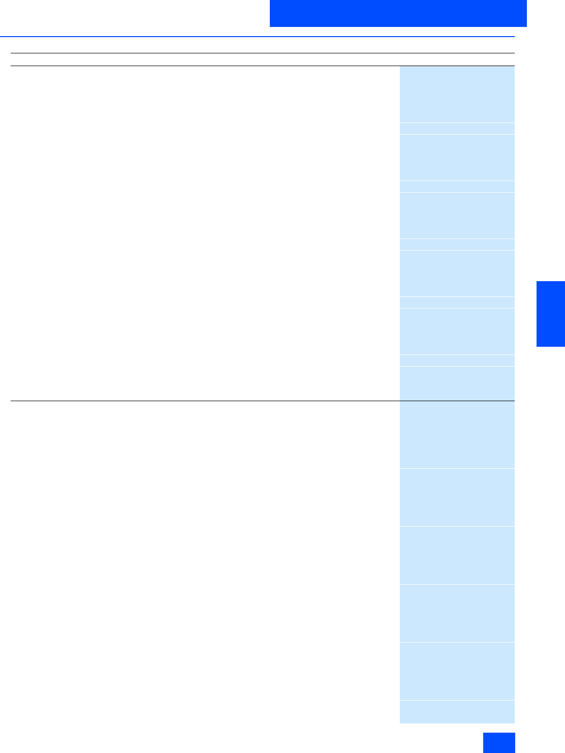
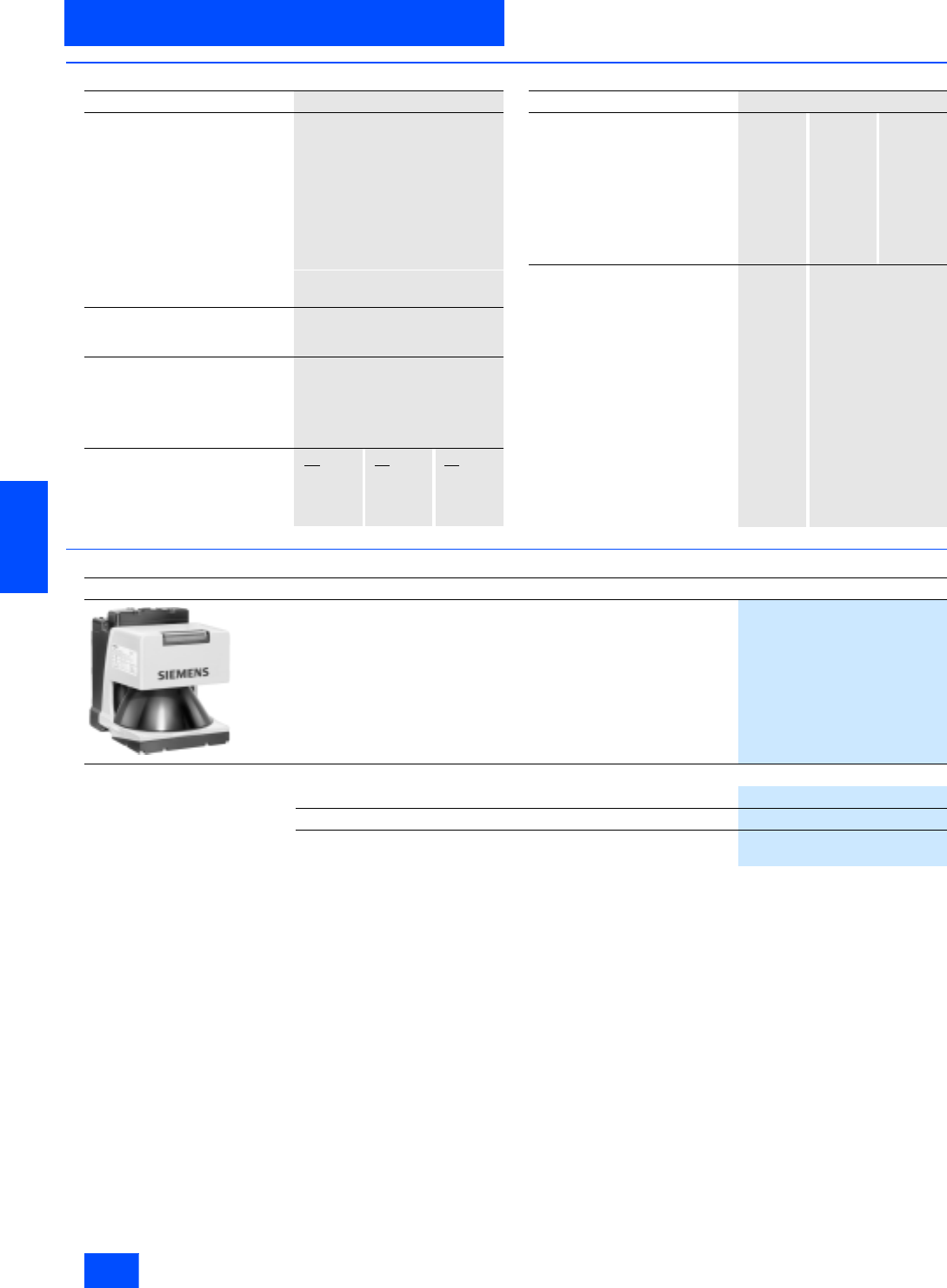
Overview
The LS4 Laser Scanner is an optical distance sensor. The device
periodically transmits light pulses within an operating range of
190°.
If the pulses hit an obstruction or a person, the light is reflected
and then received and evaluated by the LS4 laser scanner. The
scanner calculates the precise coordinates of the obstruction
"seen" from the light propagation time.
If the obstruction or the person is located within defined ranges,
a Stop function is executed. Switch-off is then performed via the
safe interface within the system response time.
The Stop function is reset when the protective zone is free again,
depending on the operating mode, either automatically or follow-
ing acknowledgement.
Accessories
Accessories include a twistable mounting support, suitable pre-
assembled connecting cables in diverse lengths as well as
spare parts.
Siemens IK PI · 2004 6/25
AS-Interface
AS-Interface Safety at work
AS-Interface laser scanner LS4
6
■
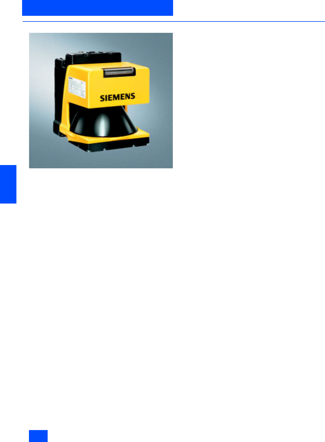
Application
Horizontal danger zone protection
Reliable detection of persons and objects in danger zones of
machines and plants
Flexible configuration of any protection and warning zones to a
great extent
Horizontal danger zone protection with several zones
to be protected
Safe detection of persons in various danger zones by switching
over protection zones
Better availability when specifically securing only live zones
Route monitoring for driverless transport systems
Detection of persons and objects that approach the vehicle
The laser scanner offers a greater protection range than
bumpers and therefore permits higher speeds.
Collision protection for shifting units
Protection of persons who are in the path of the vehicle
Objects in the path of the vehicle are detected early; damage to
the vehicle or load is therefore prevented.
Further applications
• All types of hazardous area protection,
• Room protection and access protection,
• Projecting object monitoring (protection of machines and
persons)
• Non-safety-related measurement or recognition tasks
(e. g. distance, position or contour recognition)
Siemens IK PI · 2004
6/26
AS-Interface
AS-Interface laser scanner LS4
AS-Interface Safety at work
6
■
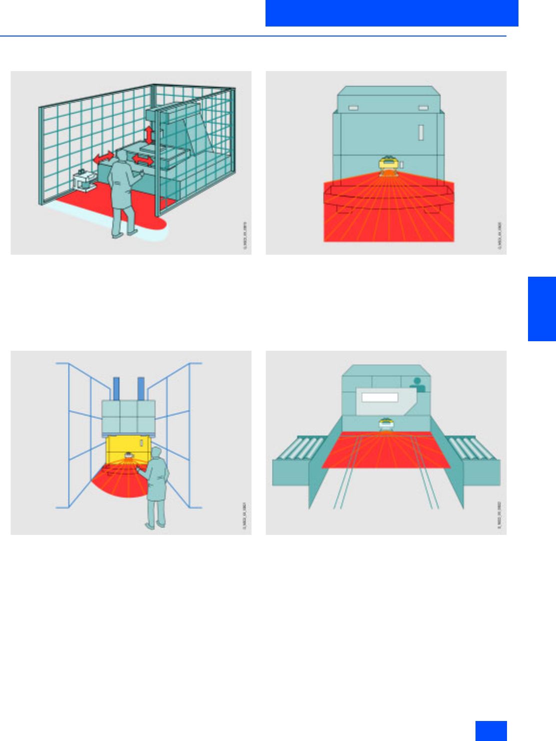
Function
Function principle
Bundled light pulses are created via a laser diode with coupled
transmission optics. These are diverted by a rotating mirror in
such a way that within 40 ms a light pulse is triggered in all angle
segments (scan rate: 25 scans/s). If the light pulse hits an object
or a person, the light is reflected and acquired and evaluated by
the scanner.
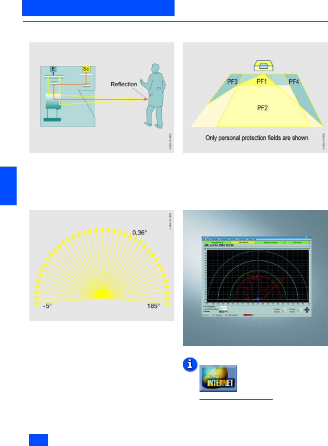
Measuring pulse propagation time
The SIGUARD LS4 laser scanner operates by measuring the
pulse propagation time. When extremely short light pulses are
emitted, a time difference occurs between the transmitted and
received light pulse. The propagation time of the light pulse is a
direct measurement of the target distance.
The operating range of the scanner (190°) is subdivided into
angle segments of 0.36°.
Protection and warning field pairs
The device has 4 switchable protection and warning field pairs.
LS4Soft operating software
The SIGUARD LS4 laser scanner must be parameterised using
the associated LS4Soft software. The personal protection and
warning fields required are set in this manner. Also configuration
parameters, such as automatic/manual start, response time and
restart time can be parameterised.
Additional information is available in the Internet under:
http://www.siemens.de/laserscanner

Siemens IK PI · 2004 6/27
AS-Interface
AS-Interface Safety at work
AS-Interface laser scanner LS4
6
■
Technical specifications
LS4-4 AS-Interface laser scanner 3SF7 834-6DD00
Protective zone
• Sensing range in m 0 to 4
• Luminance factor in % Min. 1.8
• Object size (diameter) in mm 70 (cylindrical test object)
• Response time
- Double evaluation (2 scans)
in ms 85
- Adjustable up to 16 scans in ms 645
•Number 4 (selectable via switch inputs)
• Safety category Category 3 according to
EN 954-1, Type 3 according to
IEC 61496-1 or EN 61496-3
•Output Safe AS-Interface connection
•Start-up Start-up testing and start-up
disable can be set separately
•Restart 160 ms to 10 s
(adjustable or manual)
Protective zone supplement
• For deactivated dust suppression
in mm 81
• For activated dust suppression
in mm
- For protective zone size
< 3.5 mm 81
- For protective zone size
> 3.5 mm 98
• Additional for reflectors in mm
- Over 1.2 m behind the
protective zone line 0
- In the protective zone or up to
1.2 m behind the protective
zone line
110
Warning zone
• Sensing range in m 0 to 15
• Luminance factor in % Min. 20
• Object size in mm 150 150
• Response time in ms
- Double evaluation (2 scans) 85
- Adjustable up to 16 scans 645
• Number of warning zones 4 (selectable via switch inputs)
•Output Connection of AS-Interface
Contour measurement
• Sensing range in m 0 to 50
• Luminance factor in % Min. 20
•Output RS 232 serial interface
via infra-red interface
• Radial resolution in mm 5
• Lateral resolution in ° 0.36
Supply voltage
• Via AS-Interface network in V 29.5 to 31.6 (according to AS-
Interface specification)
• Via AS-Interface auxiliary voltage
in V Up to DC 30
• Via external supply in V 24 DC (+/-20 %)
•Note The power supply unit for the
external supply voltage as well as
the AS-Interface power supply
unit for supplying the AS-Inter-
face components must feature
safe mains isolation according to
IEC 60742 and must bridge tem-
porary mains failures of up to
20 ms (e.g. AS-Interface power
pack 3RX9 307-0AA00)
Overcurrent protection 1.25 A fuse, medium-slow
Supply current in mA Typ. 350
LS4-4 AS-Interface laser scanner 3SF7 834-6DD00
Inputs
• Restart/Reset Connection of a command device
for "with restart lockout“ operating
mode and/or device resets,
dynamically monitored,
24 V DC opto-decoupled
• Zone-pair switchover Selection of zone pairs via
4 control cables with internal
monitoring (one zone pair =
one protective zone and one
warning zone),
24 V DC opto-decoupled
• Signal definition in V
- High (logical 1) 16 to 30
- Low (logical 0) < 3
• AS-Interface address
programming Connection of a generally
available AS-Interface address
programmer
RS232 interfaces for each infrared
interface For device parameterization and
zone function
Optical system
• Angular zone in ° 190
• Angular resolution in ° 0.36
• Lateral tolerance in °
- Without mounting system (with
reference to the rear panel of the
housing)
0.18
- With mounting system (with ref-
erence to the mounting surface) 0.22
• Scan rate 25 scans/s or 40 ms/scan
• Laser protection class
- According to standard EN 60825-1, Class 1
(safe for eyes)
- Wave length in nm 905
- Beam divergence in mrad 2
- Time base in s 100
Degree of protection IP65
Ambient temperature in °C
•Operation 0 to +50
•Storage -20 to +60
Housing insulation class Protection class 2
Humidity Acc. to DIN 40040, Table 10,
Code Letter E (medium dry)
Dimensions (W x H x D) in mm 140 168 165
Control cable X3
• Length in m Max. 50 (for cable cross-section
of 0.5 mm2, shielded)
•Note Shield must be connected to PE
at the cabinet end only
Transmitter Infrared laser diode ( = 905 nm)
Dimension spacing in mm
• Middle of the scan plane to
bottom edge of housing 48,75
• Rear edge of housing to axis of
rotating mirror 101
Housing
•LS4 Cast aluminum, plastic
• AS-Interface rucksack Plastic, steel connection plate
Vibration stress over three axes
acc. to IEC 60068, Part 2-6 10 to 150 Hz, max. 5 g
Continuous shock over three axes
acc. to IEC 60068, Part 2-29 10 g, 16 ms
Rotating mirror drive Brushless DC motor
Rotating mirror bearings Maintenance-free ball bearings
Siemens IK PI · 2004
6/28
AS-Interface
AS-Interface laser scanner LS4
AS-Interface Safety at work
6
■
Technical specifications (continued)
■
Selection and Ordering data
LS4-4 AS-Interface laser scanner 3SF7 834-6DD00
AS-Interface
• ID code B
• I/O code 0 (four data bits as outputs)
• Slave address Programmed by the user in the
range 1 to 31 (delivery status = 0)
• Cycle time according to
AS-Interface specification in ms 5
• Profiles Safe slave
• Electrical connection
-X1 M 12 plug, AS-Interface
-X2 M 12 plug, 24 V external
Assignment of data bits D0 ... D3 Protective zone empty:
Code sequence
Protective zone occupied: 0
Assignment of the diagnostic
parameter bits P0 = Alarm (according to LS4
programming)
P1/2 = SF coding
(see assignment of SF coding)
P3 = LS4-RESET (via PC/AS-
Interface master call)
Assignment of SF coding P2
0
0
1
1
P1
0
1
0
1
SF
1
2
3
4
LS4-4 AS-Interface laser scanner 3SF7 834-6DD00
Assignment PIN1 PIN2 PIN3
• X1 (M12 plug for device
connection) AS-i+ -- AS-i-
• X2 (M12 connector for external
power supply) 24 V DC
supply 24 V Out Mass
• X3 (M12 socket for protective
zone changeover) SF pair 1 SF pair 2 SF pair 3
• X4 (AS-Interface addressing
socket) AS-i+ AS-i- --
Assignment PIN 4 PIN 5
• X1 (M12 plug for device
connection) – –
• X2 (M12 connector for external
power supply) Start/
Reset PE
• X3 (M12 socket for protective
zone changeover) SF pair 4 24 V Out
• X4 (AS-Interface addressing
socket) – –
Design
Order No.
AS-Interface LS4-4 laser scanner
Including LS4soft Software
3SF7 834-6DD00
Accessories
Mounting system
3RG7 838-1AA
Adapter plate
3RG7 838-1AB
PC cable connector
Including plug, 9-pole and optical interface
3RG7 838-1DC
Siemens IK PI · 2004 6/29
AS-Interface
AS-Interface Safety at work
AS-Interface laser scanner LS4
6
■
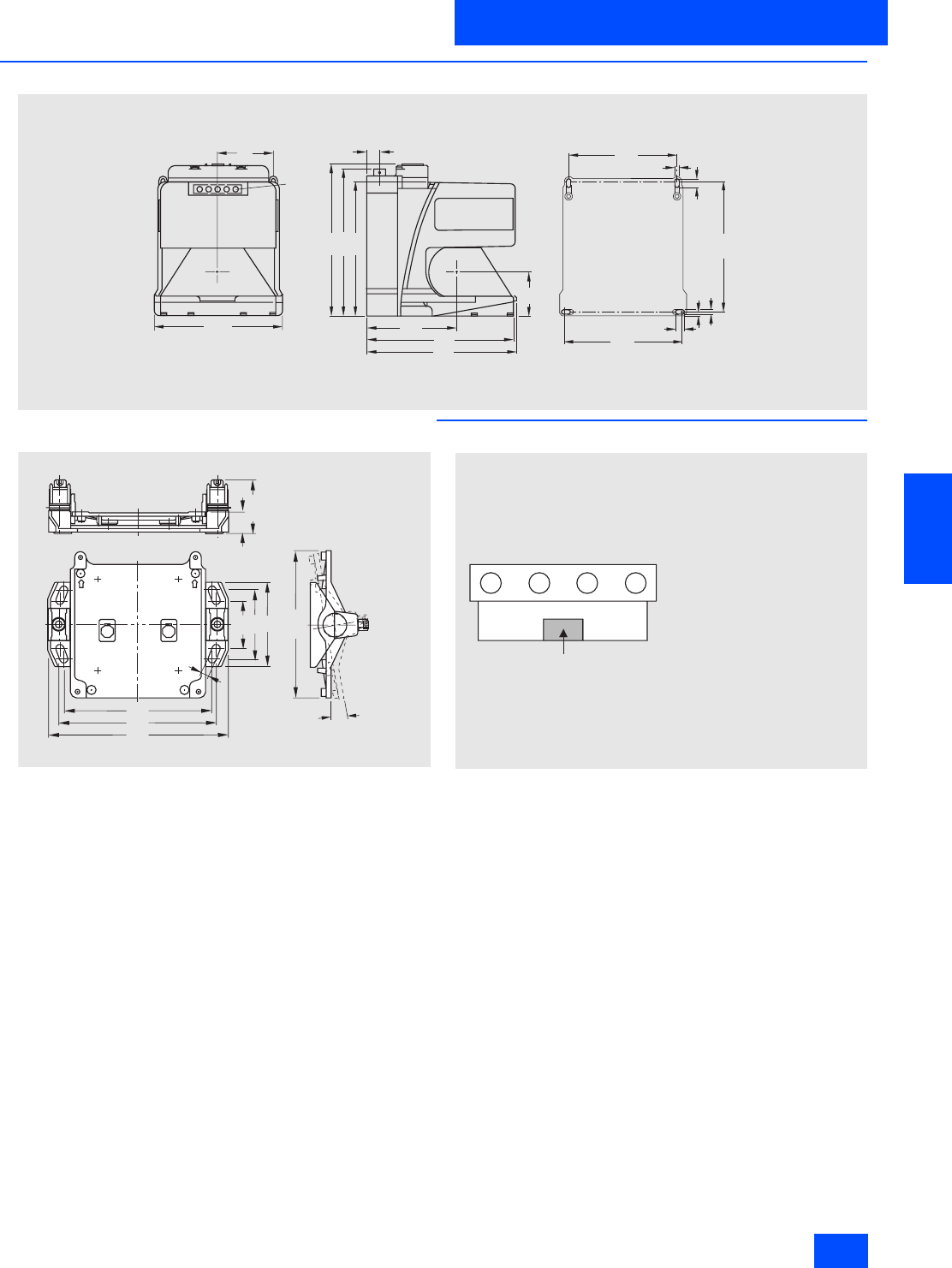
Dimensional drawings
LS4 laser scanner
Assembly system
■
Schematics
N S C 0 _ 0 0 6 3 0
149
163
168
101
165
168
4 9
1 3 , 5
6 1
L E D
( 5 x )
140
5 , 2
144
5
9 , 5
129
5 , 2
122
9 , 5
23
56,6
51,5
74,4
90
158
166
192
155,4
9°
NSC 00610
9
X 2
N S C 0 _ 0 0 6 3 1 a
X 3 X 4 X 1
O p t i c a l i n t e r f a c e
M 1 2 c o n n e c t o r , A S - I n t e r f a c e
M 1 2 c o n n e c t o r ,
o p t i o n a l a u x i l i a r y v o l t a g e
M 1 2 s o c k e t , p r o t e c t i o n f i e l d
c h a n g e - o v e r
A d d r e s s i n g s o c k e t ,
A S - I n t e r f a c e
X 1 :
X 2 :
X 3 :
X 4 :
Siemens IK PI · 2004
6/30
AS-Interface
AS-Interface EMERGENCY STOP pushbuttons
AS-Interface Safety at work
6
■
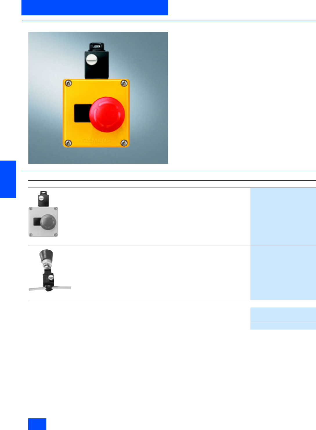
Overview
It is also possible now to connect EMERGENCY STOP devices
via the standard AS-Interface with safety-oriented communica-
tion. This only applies to EMERGENCY STOP devices of the
SIGNUM 3SB3 command devices for front panel installation and
for installation in an enclosure.
■
Selection and Ordering data
1) See Catalog LV 10, Section Pushbuttons and Indicator Lamps
Design
Order No.
3SF5 801-3AA08
AS-Interface EMERGENCY STOP housing
Two NC contacts
AS-Interface F adaptor
• Yellow cover
3SF5 801-3AA08
• Yellow cover with protective collar
3SF5 801-3AB08
3SF5 402-1AA01
AS-Interface EMERGENCY STOP front plate /
AS-Interface F adaptor
For AS-Interface EMERGENCY STOP
Front panel mounting
EMERGENCY STOP actuator is not included 1)
3SF5 402-1AA01
Accessories
Safety Integrated manual
•German
E20001-A110-M103
• English
E20001-A110-M103-X-7600
Siemens IK PI · 2004 6/31
AS-Interface Master
Masters for SIMATIC S5
CP 2430
6
■
Overview
• Master connection for SIMATIC S5-115U to -155U
• Simple operation in the I/O address area of the
SIMATIC S5-115U, -135U, -155U
• No need for CP configuration
• Two AS-Interface masters in one module
• Control of up to 2 x 31 AS-Interface slaves according to
AS-Interface Specification V2.0
• Up to 496 binary elements can be controlled when using bi-
directional slaves
• Monitoring of the supply voltage on the AS-Interface shaped
cable
■
Benefits
• Saving on slots and costs because two AS-Interface masters
are located on one module
• Shorter startup times due to easy configuration at the press of
a button
• Reduction of standstill or service times in the event of a fault
through LED displays:
- status of the AS-Interface network
- connected slaves and their operational readiness
- monitoring of the AS- Interface voltage level
■
Application
Master connection for:
• SIMATIC S5-115U:
CP can be inserted at CP slots in the central controller and
expansion unit
• SIMATIC S5-135/S5-155U:
For exclusive use of I/O mode can be plugged into the I/O slots
in the central controller and expansion unit; in cache mode, CP
can be inserted at CP slots in the central controller and expan-
sion unit
• Up to four CP 2430s can be used in the PLC, depending on
PLC configuration.
■
Design
• Two AS-Interface masters in one module
• Occupies a slot in SIMATIC S5
• For operation in the S5-115U an adapter casing is required.
• In I/O mode 32 byte are used in the I/O address space
• Display of the connected and activated slaves and their oper-
ational readiness
• Connection of the two AS-Interface cables through connectors
with terminal strip (solder-free connection with screw lock)
• One pushbutton per master unit for switching the operating
status and entering the existing configuration
■
Function
Each of the AS-Interface masters in the CP 2430 independently
controls its own AS-Interface segment with up to 31 AS-Interface
slaves. This allows control of a maximum of 2 x 31 AS-Interface
slaves with a total of 248 binary sensors/actuators (496 when bi-
directional slaves are used).
The front plate has separate status indicators for each master
section, and a common LED matrix display for the active slaves.
The module address, page address and mode are set through
encoding switches.
Two modes:
• Standard mode
Only the data bits of the slaves in the I/O address space of the
PLC can be accessed in this operating mode. No master calls
can be executed.
• Extended mode
Access to the master calls is provided through data handling
blocks and the page interface in accordance with the AS-Inter-
face Specification V2.0 (e.g. writing parameters).
User interface
There is a choice of three versions:
• I/O operation:
Only access to slave data in the I/O address space, no master
calls
• I/O and page mode:
Access to slave data in the I/O address space and master calls
through page access
•Page mode:
Access to slave data and master calls through page access
$6,QWHUIDFH0DVWHU

Siemens IK PI · 2004
6/32
AS-Interface Master
CP 2430
Masters for SIMATIC S5
6
■
Technical specifications
■
Ordering data Order No.
Bus cycle time 5 ms with 31 slaves
AS-Interface Specification V 2.0
Interfaces
• I/O address space used i
n the PLC 32 byte in I/O operation
• AS-Interface connection 2 x 4-pin socket for connector
with terminal clamp
Supply voltage +5 V DC through backplane bus
Current consumption
• Through backplane bus Typ. 700 mA at 5 V DC
• From the AS-Interface shaped
cable Max. 100 mA per AS-Interface
segment
Power loss 7.9 W
Perm. environmental conditions
• Operating temperature 0°C to +60°C
• Transport/storage temperature -40 °C to +70 °C
• Relative humidity max. 95% at +25 °C
Design
• Module format Double-height Eurocard format
• Dimensions (W x H x D) in mm 160 x 233.4 x 20.32
•Weight 400 g
• Space required 1 slot
CP 2430
communications processor
6GK1 243-0SA20
For connecting
SIMATIC S5-115U, -135U, -155U
to AS-Interface;
including connector
Manual for AS-Interface
Including:
CP 2413/CP 2430/CP2433 Manual,
Introduction and Fundamentals;
including software
(FB60 and examples)
•German
6GK1 971-2SA01-0AA0
Electronic manuals
6GK1 975-1AA00-3AA0
Communications systems,
protocols, products
on CD-ROM
German/English
Siemens IK PI · 2004 6/33
AS-Interface Master
Masters for SIMATIC S7
CP 142-2
6
■
Overview
• Master connection for the distributed I/O system ET 200X at
AS-Interface through 12-pin connector
• Simple operation in the I/O address area of SIMATIC ET 200X
• No need to configure CP for AS-Interface
• Addressing of up to 31 AS-Interface slaves according to the
AS-Interface Specification V2.0
• Monitoring of the supply voltage on the AS-Interface shaped
cable
• Considerable increase in the number of inputs/outputs of the
ET 200X.
■
Benefits
• In connection with the BM 147, the ET 200X enables PLC func-
tionality in degree of protection IP65
• Can also be used in a rugged industrial environment without
additional casing due to the high degree of protection IP67
• More flexible and extended application options of the ET 200X
thanks to considerable increase in available inputs/outputs
• Shorter startup times due to easy configuration at the press of
a button
• Reduction of standstill or service times in the event of a fault
through LED displays:
- status of the AS-Interface network
- connected slaves and their operational readiness
- monitoring of the AS- Interface voltage level
■
Application
The CP 142-2 enables the connection of the distributed I/O sys-
tem ET 200X to AS-Interface.
This module can be used to activate up to 31 AS-Interface
slaves and, if bi-directional slaves are implemented, up to 248
binary components.
Up to 6 CP 142-2 can be operated on the ET 200X.
■
Design
• 16 byte inputs and 16 byte outputs are used in the address
space of the ET 200X
• Operating statuses displayed by LEDs in the frontplate
• Display of the connected and activated slaves and their oper-
ational readiness by LEDs
• One pushbutton for switching the operating status, entering the
existing configuration and switching the display
• Connection of the AS-Interface cable to M12 connector
• Monitoring of the supply voltage on the AS-Interface cable
■
Function
The CP 142-2 can be used in two operating modes:
• Standard mode with BM 141/BM 142/BM 147
• A maximum of all 124 input and output bits of the AS-Interface
slaves can be addressed.
• Extended mode with BM 147
A function call facilitates master calls in accordance with the
AS-Interface Specification V2.0 (e.g. writing parameters).
Calls are described in the manual. The manual also contains
program examples.
System configuration
Parameter assignment
The CP 142-2 is parameterized with STEP®7 basic package as
of V2.1. Separate configuration for AS-Interface is not necessary.
01
AS-Interface
AS-Interface shaped cable
AS-Interface
ET 200X with CP 142-2
G_IK10_XX_20013
PROFIBUS

Siemens IK PI · 2004
6/34
AS-Interface Master
CP 142-2
Masters for SIMATIC S7
6
■
Technical specifications
■
Ordering data Order No.
Bus cycle time 5 ms with 31 slaves
Configuration
• AS-Interface Using pushbutton on front plate
• PROFIBUS The CP 142-2 occupies 16 byte
inputs and 16 byte outputs in the
PROFIBUS configuration of the
ET 200X
AS-Interface Specification V 2.0
• With BM 141/BM 142 Only I/O transmission
• With BM 147 and FC, ASI-3422 All functions
Connection of the AS-Interface
cable Through M12 connector on the
front plate
Address range 16 input bytes
16 output bytes
Supply voltage
• Through backplane bus 24 V DC
• From the AS-Interface shaped
cable According to the AS-Interface
Specification V2.0
Power loss 2 W
Current consumption
• Through backplane bus Typ. 50 mA at 24 V DC
• Through AS-Interface from the
AS-Interface shaped cables According to the AS-Interface
specification V 2.0
Perm. environmental conditions
• Operating temperature 0°C to +55°C
• Transport/storage temperature -40 °C to +70 °C
• Relative humidity 95% at +25 °C
Design ET 200X design
• Module format Expansion module
• Dimensions (W x H x D) in mm 87 x 110 x 63
•Weight Approx. 310 g
• Space required 1 slot
Degree of protection IP66/67
CP 142-2
communications processor
6GK7 142-2AH00-0XA0
For connecting SIMATIC ET 200X
to AS-Interface
CP 142-2 manual
6GK7 142-2AH00-8AA0
•German
Electronic manuals
6GK1 975-1AA00-3AA0
Communications systems,
protocols, products
on CD-ROM
German/English
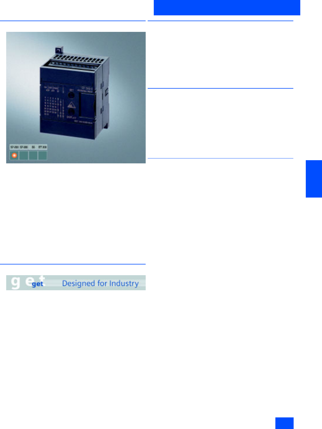
Siemens IK PI · 2004 6/35
AS-Interface Master
Masters for SIMATIC S7
CP 243-2
6
■
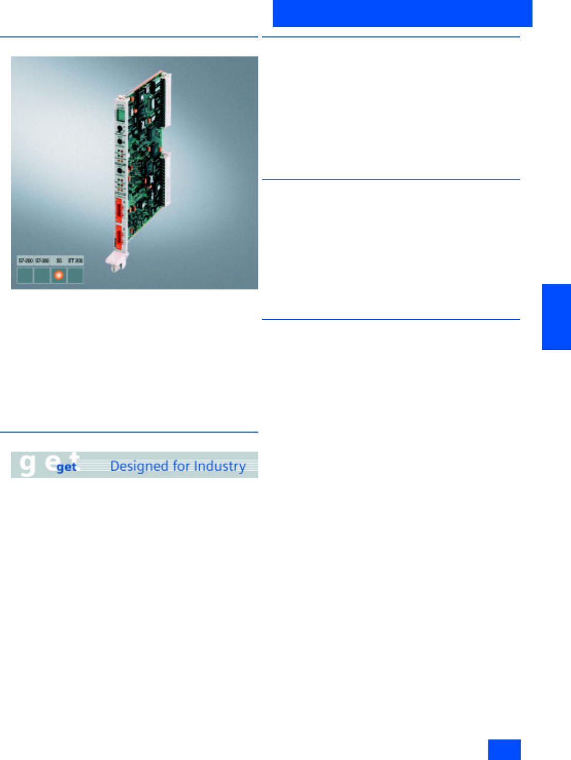
Overview
The CP 243-2 is the AS-Interface master for the new generation
of SIMATIC S7-200. The communications processor (6GK1 243-
2AX01-0AX0) supports the expanded AS-Interface specification
V2.1 and has the following functions:
• Connection of up to 62 AS-Interface slaves and integrated an-
alog value transmission (according to expanded AS-Interface
Specification V2.1)
• Supports all AS-Interface master functions according to ex-
panded AS-Interface Specification V2.1
• Display of operating status and operational readiness of the
connected slaves through LEDs in the frontplate
• Display of errors (incl. AS-Interface voltage errors, configura-
tion errors) through LEDs in the frontplate
• Compact housing in the design of the innovative SIMATIC
S7-200 generation
■
Benefits
• More flexible and extended application options of the SIMATIC
S7-200 due to the considerable increase in the available digital
and analog inputs/outputs
• Shorter startup times due to easy configuration at the press of
a button
• In the event of a fault, shorter standstill and service times due
to LED indication of:
• Status of the CPs
- connected slaves and their operational readiness
- monitoring of the AS-Interface voltage level
■
Application
The CP 243-2 is the AS-Interface master connection exclusively
for the CPUs 22x of the innovated SIMATIC S7-200 generation.
By connecting to AS-Interface, the available digital inputs and
outputs for S7-200 are significantly increased (max. 248 DI /
186 DO on AS-Interface per CP).
In addition, the integrated analog value processing also makes
analog values (per CP max. 31 analog slaves, each with up to
4 channels) available to the S7-200 at the AS-Interface. Up to
two CP 243-2s can be operated simultaneously on the S7-200.
■
Design
The CP 243-2 is connected to the S7-200 like an expansion
module. It features:
• Two terminals for direct connection of the AS-Interface cable
• LEDs in the front panel for displaying the operating status and
the operational readiness of all connected and activated
slaves
• Two pushbuttons for displaying the status information of the
slaves, for switching the operating status and entering the
existing ACTUAL configuration as the SETPOINT configuration
■
Function
The CP 243-2 supports all functions stipulated in the expanded
AS-Interface Specification V2.1. Double address assignment
(A-B) makes it possible to operate up to 62 digital or 31 analog
slaves at the AS-Interface.
Access to analog values is just as easy as access to digital val-
ues, thanks to the integrated analog value processing.
The CP 243-2 occupies one digital input byte (status byte), one
digital output byte (control byte) and 8 analog input and 8 analog
output words in the process image of the S7-200. This means
that the CP 243-2 occupies two slots. The operating mode of the
CP 243-2 can be set with the status and control byte through the
application program.
Depending on the operating mode, the CP 243-2 either stores
the I/O data of the AS-Interface slaves or diagnostic values in the
analog address space of the S7-200 or enables master calls
(e.g. readdressing of slaves).
All connected AS-Interface slaves are configured at the press of
a button. No further configuration of the CP is necessary.

Siemens IK PI · 2004
6/36
AS-Interface Master
CP 243-2
Masters for SIMATIC S7
6
■
Technical specifications
■
Ordering data Order No.
AS-Interface Specification V 2.1
Interfaces
• Address space used in the PLC Corresponding to 2 I/O modules
(8 DI/8 DO and 8 AI/8 AO)
• AS-Interface connection Term inal
Current consumption
• Via AS-Interface Max. 100 mA
• Through backplane bus Typ. 220 mA at 5 V DC
Power loss Approx. 2 W
Perm. environmental conditions
• Operating temperature
- Horizontal mounting 0°C to +55°C
- Vertical mounting 0°C to +45°C
• Transport/storage temperature -40 °C to +70 °C
• Relative humidity Max. 95% at +25 °C
Design
• Module format S7-22x expansion module
• Dimensions (W x H x D) in mm 71.2 x 80 x 62 (H+16 mm with
holes for wall mounting)
•Weight Approx. 250 g
• Space required 1 slot
CP 243-2
communications processor
6GK7 243-2AX01-0XA0
For connection of SIMATIC S7-200
(2nd generation) to AS-Interface
with bus connector
Manual for CP 243-2
Including AS-Interface
fundamentals and diskette
with program examples
paper version
•German
6GK7 243-2AX00-8AA0
• English
6GK7 243-2AX00-8BA0
•French
6GK7 243-2AX00-8CA0
•Spanish
6GK7 243-2AX00-8DA0
• Italian
6GK7 243-2AX00-8EA0
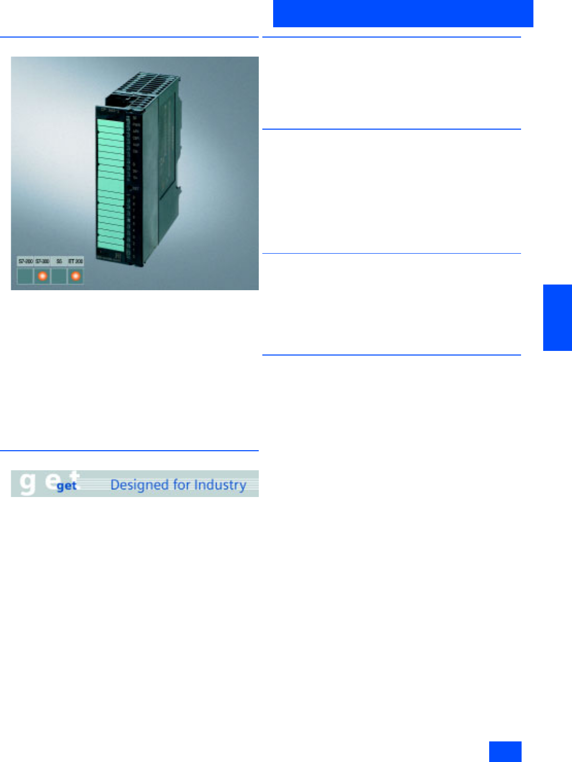
Siemens IK PI · 2004 6/37
AS-Interface Master
Masters for SIMATIC S7
CP 343-2
6
■
Overview
The CP 343-2 is the AS-Interface master for PLC SIMATIC
S7-300 and the distributed I/O device ET 200M. The communi-
cations processor offers the following functions:
• Connection of up to 62 AS-Interface slaves and integrated an-
alog value transmission (according to expanded AS-Interface
Specification V2.1)
• Supports all AS-Interface master functions according to ex-
panded AS-Interface Specification V2.1
• Display of operating status and operational readiness of the
connected slaves through LEDs in the frontplate
• Display of errors (incl. AS-Interface voltage errors, configura-
tion errors) through LEDs in the frontplate
• Compact housing in the design of the SIMATIC S7-300
■
Benefits
• Shorter startup times due to easy configuration at the press of
a button
• Flexible decentralized topologies can be constructed by using
this communications processor in the ET 200M DP slave.
• Reduction of standstill or service times in the event of a fault
through LED displays:
- status of the AS-Interface network
- connected slaves and their operational readiness
- monitoring of the AS- Interface voltage level
• Reduced costs for spare parts inventories because the CP can
be used in both the SIMATIC S7-300 and in ET 200M.
• Ideal for complex applications through the connection option
of 62 slaves and integrated analog value processing
■
Application
The CP 343-2 is the AS-Interface master connection for SIMATIC
S7-300 and ET 200M. Connection to the AS-Interface allows ac-
cess to max. 248 DI/186 DO per CP.
The integrated analog value processing also supports evalua-
tion of very simple analog signals (per CP at max. 31 analog
slaves, each with four channels).
■
Design
The CP 343-2 is connected to the S7-300 like an expansion
module. It features:
• Two terminals for direct connection of the AS-Interface cable
• LEDs in the frontplate for displaying the operating status and
the operational readiness of all connected and activated
slaves
• Pushbuttons for displaying the status information of the slaves,
for switching the operating status and entering the existing
ACTUAL configuration as the SETPOINT configuration
■
Function
The CP 343-2 supports all functions stipulated in the expanded
AS-Interface Specification V2.1. Double address assignment (A-
B) makes it possible to operate up to 62 digital or 31 analog
slaves at the AS-Interface. Access to analog values is easy
thanks to the integrated analog value processing.
All connected AS-Interface slaves are configured at the press of
a button. No further configuration of the CP is necessary.
■
Mode of operation
In I/O mode, the CP 343-2 reserves 16 bytes in the analog ad-
dress space of the SIMATIC S7-300. The I/O data of the standard
slaves or A slaves is stored here. The I/O data of the B slaves can
be accessed using the "read/ write data record “ function.
A and B slaves are slaves in accordance with the extended
AS-Interface specification V2.1. For the AS-Interface master
calls (e.g. Write parameter, read diagnostic values), a Function
Call (FC) is provided on the diskette that accompanies the
manual.

Siemens IK PI · 2004
6/38
AS-Interface Master
CP 343-2
Masters for SIMATIC S7
6
■
Technical specifications
■
Ordering data Order No.
AS-Interface Specification V 2.1
Bus cycle time 5 ms for 31 slaves
10 ms for 62 slaves
Interfaces
• Assignment of analog address
space in the PLC 16 byte I/O and P-bus S7-300
• AS-Interface connection S7-300 front connector
with terminal
Supply voltage +5 V DC through backplane bus
Current consumption
• through backplane bus Typ. 200 mA at 5 V DC
• through AS-Interface from the
AS-Interface shaped cables Max. 100 mA
Power loss 2 W
Perm. environmental conditions
• Operating temperature 0°C to +60°C
• Transport/storage temperature -40 °C to +70 °C
• Relative humidity, max. 95% at +25 °C
Design
• Module format S7-300 design
• Dimensions (W x H x D) in mm 40 x 125 x 120
•Weight Approx. 190 g
• Space required 1 slot
CP 343-2
communications processor
6GK7 343-2AH00-0XA0
For connection of SIMATIC S7-300
and ET 200M to the AS-Interface;
without front connector
Front connector
6ES7 392-1AJ00-0AA0
20-pin, with screw contacts
CP 343-2 and CP 343-2 P manual
including software (FC)
and examples
paper version
•German
6GK7 343-2AH00-8AA0
• English
6GK7 343-2AH00-8BA0
•French
6GK7 343-2AH00-8CA0
•Spanish
6GK7 343-2AH00-8DA0
• Italian
6GK7 343-2AH00-8EA0
Electronic manuals
6GK1 975-1AA00-3AA0
Communication systems, logs,
products
on CD-ROM
German/English

Siemens IK PI · 2004 6/39
AS-Interface Master
Masters for SIMATIC S7
CP 343-2 P
6
■
Overview
The CP 343-2 P is the AS-Interface master for PLC SIMATIC
S7-300 and the distributed I/O device ET 200M. The communi-
cations processor offers the following functions:
• Supports configuration of the AS-Interface network with STEP 7
V5.2 and higher
• Connection of up to 62 AS-Interface slaves and integrated an-
alog value transmission (according to expanded AS-Interface
Specification V2.1)
• Supports all AS-Interface master functions according to ex-
panded AS-Interface Specification V2.1
• Display of errors (incl. AS-Interface voltage errors, configura-
tion errors) through LEDs in the frontplate
• Compact housing in the design of the SIMATIC S7-300
■
Benefits
• Improved plant documentation and support for servicing
thanks to documentation of the AS-Interface configuration in
the STEP 7 project
• Diagnosis of the AS-Interface network is supported
• Shorter startup times due to easy configuration at the press of
a button
• Flexible decentralized topologies can be constructed by using
this communications processor in the ET 200M DP slave.
• Reduction of standstill or service times in the event of a fault
through LED displays:
- status of the AS-Interface network
- connected slaves and their operational readiness
- monitoring of the AS- Interface voltage level
• Reduced costs for spare parts inventories because the CP can
be used in both the SIMATIC S7-300 and in ET 200M.
• Ideal for complex applications through the connection option
of 62 slaves and integrated analog value processing
■
Application
The CP 343-2 P is the AS-Interface master connection for
SIMATIC S7-300 and ET 200M. Connection to the AS-Interface
allows access to max. 248 DI/186 DO per CP.
The integrated analog value processing also supports evalua-
tion of very simple analog signals (per CP at max. 31 analog
slaves, each with four channels).
The CP 343-2 P functionality is identical to that of the CP 342-2.
An old S7 user program can therefore be used with the new
CP without any limitations. Also, the AS-Interface configuration
can be downloaded or uploaded with the STEP 7 hardware con-
figuration.
■
Design
The CP 343-2 P is connected to the S7-300 like an expansion
module. It features:
• Two terminals for direct connection of the AS-Interface cable
• LEDs in the frontplate for displaying the operating status and
operational readiness of all connected and activated slaves
• Pushbuttons for displaying the status information of the slaves,
for switching the operating status and entering the existing
ACTUAL configuration as the SETPOINT configuration
■
Mode of operation
In I/O mode, the CP 343-2 P reserves 16 bytes in the analog
address space of the SIMATIC S7-300. The I/O data of the
standard slaves or A slaves is stored here. The I/O data of the B
slaves can be accessed using the "read/ write data record “
function.
A and B slaves are slaves in accordance with the extended
AS-Interface specification V2.1. For the AS-Interface master
calls (e.g. Write parameter, read diagnostic values), a Function
Call (FC) is provided on the diskette that accompanies the
manual.
All connected AS-Interface slaves are configured at the press of
a button. No further configuration of the CP is necessary.
■
Function
The CP 343-2 P supports all functions stipulated in the ex-
panded AS-Interface Specification V2.1. Double address
assignment (A-B) makes it possible to operate up to 62 digital or
31 analog slaves at the AS-Interface. Access to analog values is
easy thanks to the integrated analog value processing.
The CP 343-2 P enables the AS-Interface configuration to be
read out with STEP 7 V5.2 and higher.

Siemens IK PI · 2004
6/40
AS-Interface Master
CP 343-2 P
Masters for SIMATIC S7
6
■
Technical specifications
■
Ordering data Order No.
AS-Interface Specification V 2.1
Bus cycle time 5 ms for 31 slaves
10 ms for 62 slaves
Interfaces
• Assignment of analog address
space in the PLC 16 byte I/O and P-bus S7-300
• AS-Interface connection S7-300 front connector
with terminal
Supply voltage +5 V DC through backplane bus
Current consumption
• Through backplane bus, typical 200 mA at 5 V DC
• Through AS-Interface from the
AS-Interface shaped cables, max. 100 mA
Power loss 2 W
Perm. environmental conditions
• Operating temperature 0°C to +60°C
• Transport/storage temperature -40 °C to +70 °C
• Relative humidity, max. 95% at +25 °C
Design
• Module format S7-300 design
• Dimensions (W x H x D) in mm 40 x 125 x 120
•Weight Approx. 190 g
• Space required 1 slot
Configuration software Optional:
STEP 7 V5.2 or later
CP 343-2 P
communications processor
6GK7 343-2AH10-0XA0
For connection of SIMATIC S7-300
and ET 200M to the AS-Interface;
without front connector
CP 343-2 and CP 343-2 P manual
including software (FC)
and examples
paper version
•German
6GK7 343-2AH00-8AA0
• English
6GK7 343-2AH00-8BA0
•French
6GK7 343-2AH00-8CA0
•Spanish
6GK7 343-2AH00-8DA0
• Italian
6GK7 343-2AH00-8EA0
Electronic manuals
6GK1 975-1AA00-3AA0
Communication systems, logs,
products
on CD-ROM
German/English
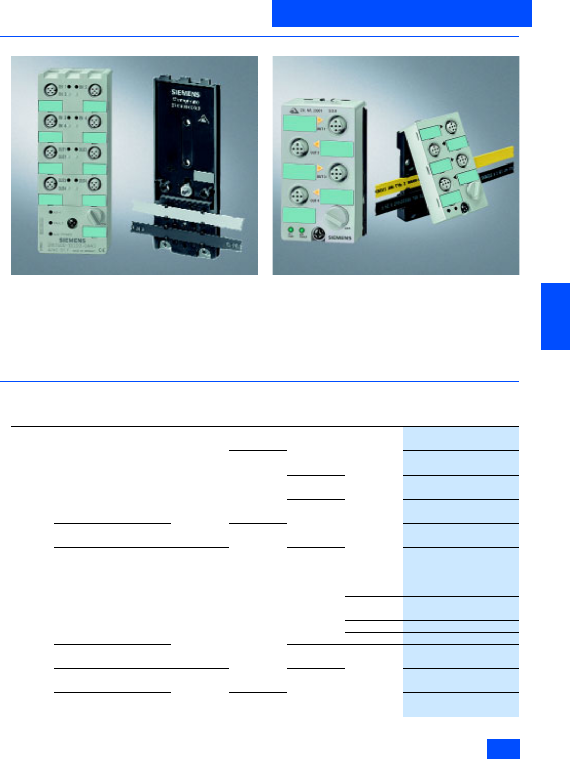
Siemens IK PI · 2004 6/41
AS-Interface Slaves
I/O modules for operation in the field
Introduction
6
■
Overview
K60
The AS-Interface compact modules belong to a new generation
of AS-Interface modules designed to a high degree of protec-
tion. They include digital, analog and pnewmatic compact mod-
ules.
They comprise a top section which is the actual module and a
base section which is the mounting plate. The top section con-
tains all the electronics, connections for sensors and actuators,
an addressing socket and status/diagnostics LEDs.
K45
The mounting plate accepts the AS-Interface flat cables and al-
lows the module to be wall mounted or snapped onto a standard
rail.
Two series of compact modules are available:
• Series K60
• Series K45
■
Selection and Ordering data
Function and order no. overview for digital compact modules 1) Start of delivery as of the end of 2003.
Seriese Type Current carry-
ing capacity
outputs
Slave-Type Pin-
assignment
Connection
technique
Order No.
K60
(digital) 8 Inputs/2 Outputs 2 A A/B special M12
3RK2 400-1HQ00-0AA3
8 Inputs – Standard Y-II
3RK1 200-0DQ00-0AA3
A/B new
3RK2 200-0DQ00-0AA3
4 Inputs/4 Outputs 2 A Standard
3RK1 400-1DQ00-0AA3
Standard
3RK1 400-1CQ00-0AA3
1 A Y-II
3RK1 400-1DQ01-0AA3
Standard
3RK1 400-1DQ03-0AA3
4 Inputs/3 Outputs 2 A A/B Y-II
3RK2 400-1FQ03-0AA3
4 Inputs/2 Outputs Standard
3RK1 400-1MQ00-0AA3
4 Inputs –
3RK1 200-0CQ00-0AA3
2 x 2 Inputs/2 x 2 Outputs 1 A Y
3RK1 400-1DQ02-0AA3
4 Outputs 2 A Y-II
3RK1100-1CQ00-0AA3
K45
(digital) 4 Inputs – Standard Standard M12
3RK1 200-0CQ20-0AA3
M8-Screw
3RK1 200-0CT20-0AA3
M8-Snap
3RK1 200-0CU20-0AA3
A/B M12
3RK2 200-0CQ20-0AA3
M8-Screw
3RK2 200-0CT20-0AA3
M8-Snap
3RK2 200-0CU20-0AA3
2 x 2 Inputs Y M12
3RK2 200-0CQ22-0AA3
2 Inputs/2 Outputs 2 A Standard Standard
3RK1 400-1BQ20-0AA3
2 x (1 Input/1 Output) 0.2 A Y
3RK1 400-0GQ20-0AA3
4 Outputs 1 A Standard
3RK1 100-1CQ20-0AA3
3 Outputs A/B
3RK2 100-1EQ20-0AA3
2 Outputs/2 Inputs 1) 2 A
3RK2 400-1BQ20-0AA3
$6,QWHUIDFH6ODYHV
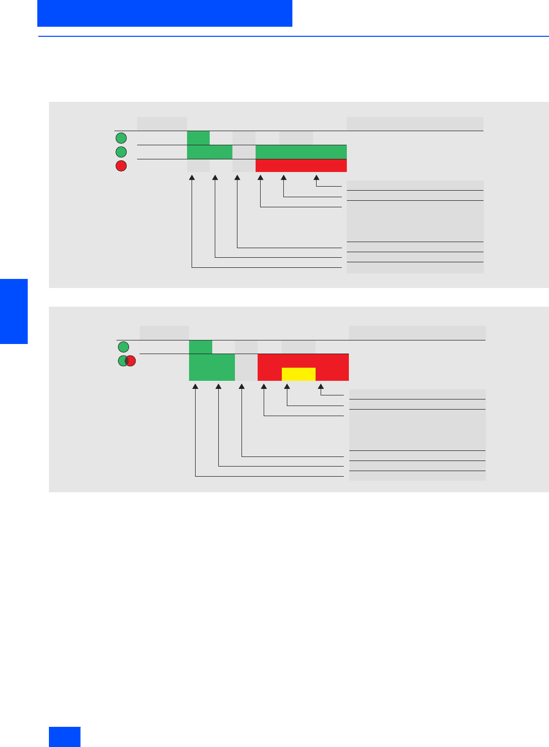
Siemens IK PI · 2004
6/42
AS-Interface Slaves
Introduction
I/O modules for operation in the field
6
■
Function
AS-Interface compact modules features comprehensive diag-
nostic indication. This supports diagnosis at a glance.
The status of a module is either displayed via two LEDs or one
dual LED with continuous or flashing light.
Compact modules of Series K60 have three LEDs for diagnostic
indication.
Compact modules of Series K45 have one single and one dual
LED (two-color LED) for status and diagnostic indication.
LED diagnostic indication of the K60 compact module
LED diagnostic indication of the K45 compact module
LED
AUX PWR1)
AS-Interface
FAULT
NSA0_00318
States
Off Off
Off
OffOff Off
Status description
On
On On On
On On
On
Flashing
Flashing
Sensor overload with RESET of slaves
Slave has address = 0
No communication:
Master in STOP mode
Slave not entered in the LPS
Slave has wrong IO&D code
Slave in RESET state
Module completely without voltage
UAux failure Normal operation and
UAux applied
LED
AUX PWR
AS-i / FAULT
NSA0_00313
States
Off Off
Off
Status description
Sensor overload with RESET of slaves
Slave has address = 0
No communication:
Master in STOP mode
Slave not entered in the LPS
Slave has wrong IO&D code
Slave in RESET state
Module completely without voltage
UAux failure
Normal operation and UAux applied
On
On On On Flashing Flashing
Flashing
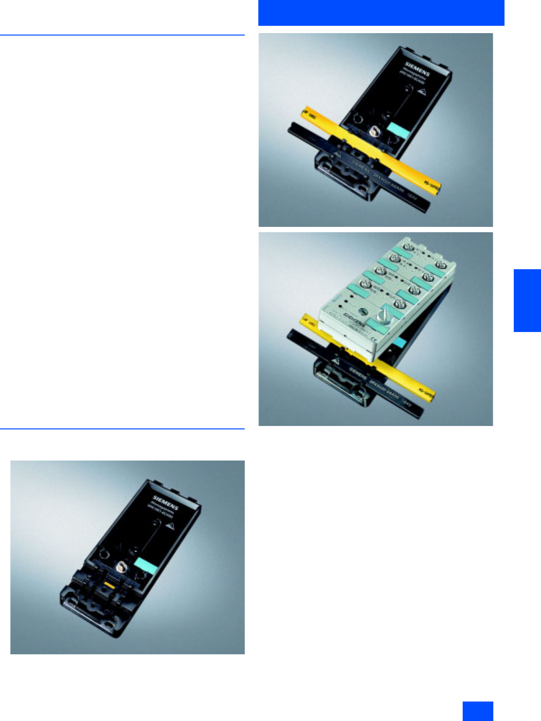
Siemens IK PI · 2004 6/43
AS-Interface Slaves
I/O modules for operation in the field
Digital I/O modules IP67 - K60
6
■
Overview
The digital AS-Interface compact modules of Series K60, are
characterized by optimized handling and greater user friendli-
ness as compared with the application modules. They enable
the user to reduce the installation and start-up times for
AS-Interface by up to 40%.
AS-Interface modules of the K60 compact series comprise two
sections:
• the mounting plate and
• the compact module.
The AS-Interface shaped cables and the compact module are
connected to the mounting plate. Two mounting plates are of-
fered for
• wall mounting and
• mounting onto standard mounting rails
AS-Interface modules of the compact series feature a connec-
tion for protective earth conductors. Addressing can also be
performed in the installed state via an addressing socket inte-
grated in the compact module.
K60 compact modules with up to four digital inputs
and outputs
These compact modules contain the communications electron-
ics and the standard M12 connections for inputs and outputs.
Up to four sensors and four actuators can be connected to the
compact module easily and reliably via standard M12 plugs.
The mounting plate and compact module are connected to-
gether with a single screw which simultaneously causes contact
to be made with the AS-Interface cable using the insulation pen-
etration technique.
K60 compact modules with up to eight digital inputs
This module has eight digital inputs which can be connected via
M12 plugs.
The module requires two AS-Interface addresses for processing
all eight inputs. The addresses can be assigned here in the
same manner as for a compact module via a double addressing
socket.
■
Design
K60 compact module
The compact modules are mounted on the mounting plate in just
two work stages:
• The AS-Interface flat cable is laid on the mounting plate.
• The module is located and fixed with a screw.
Contact is made with the AS-Interface cable by the insulation
piercing terminals integrated in the top section when the screw
is screwed down.
Addressing is performed via an integrated addressing socket.
M12 sockets that are not required must be sealed with
3RK1 901-1KA00 sealing caps in order to guarantee the speci-
fied degree of protection. The compact module with eight digital
inputs requires two AS-Interface addresses. The addresses are
assigned using a double addressing socket integrated into the
module.
K60 mounting plate
The K60 mounting plate is used for mounting digital and analog
K60 compact modules. They have cable connectors for the
yellow and black AS-Interface flat cable.
If the yellow and black AS-Interface cables are completely
routed through the module, no additional seals are necessary.
Additional seals are only necessary when both leads or only one
lead ends inside the module. In this case, additional seals
(straight and shaped) must be inserted in the mounting plate.
The seals are not included in the scope of supply and must be
ordered separately (3RK1 902-0AR00, see Selection and
Ordering data).

Siemens IK PI · 2004
6/44
AS-Interface Slaves
Digital I/O modules IP67 - K60
I/O modules for operation in the field
6
■
Technical specifications
Technical specifications common to all IP67 – K60 digital I/O modules
Operational voltage in accordance
with AS-Interface specification in V 26.5 to 31.6
Input connection PNP
Inputs
• Sensor supply via AS-Interface Short-circuit and overload
withstand capability
•Sensors 2- and 3-wire
• Voltage range in V 20 to 30
• Current carrying capacity f
or all inputs (Tu 40 °C) in mA 200
• Switching level High in V 10
• Input current Low/High in mA 1.5 / 6
Outputs
• Type of output Electronics
• Short-circuit protection Built-in
• Inductive interference protection
(free-wheeling diode) Built-in
• External 24 V DC supply voltage Over black AS-Interface flat cable
• Watchdog Built-in
AS-Interface certificate Available (or under application
in the case of new products)
Approvals UL, CSA, marine certification
(or under application in the case
of new products)
Degree of protection IP67
Ground connection PIN 5 of each M12 socket is
connected with the grounding
sheet in the mounting plate
through a pin
Ambient temperature in °C -25 to +85
Storage temperature in °C -40 to +85
Status indications
• I/O display Yellow LED
•Display UAux Green LED
• AS-Interface/diagnostics display Green/red LED
Connection Using mounting plate for K60
compact module
Note 1 All K60 compact modules are
supplied with high-grade steel
screws/sockets
Note 2 To supply the output circuit,
an external supplementary
supply (AUX POWER)
of 20 to 30 V DC is necessary.
The supplementary supply must
comply with VDE 0106 (PELV),
Safety Class III.
8 inputs/2 outputs 8 inputs 8 inputs new
2 A -- --
A/B slave Standard slaves A/B slaves
Special assignment Y-II assignment Y-II assignment
3RK2 400–1HQ00–0AA3 3RK1 200–0DQ00–0AA3 3RK2 200–0DQ00–0AA3
Total current input in mA 300 270 270
Socket assignment, inputs PIN 1 = Sensor supply L+
PIN 2 = Data input II
PIN 3 = Sensor supply L-
PIN 4 = Data input I
PIN 5 = Earth connection
PIN 1 = Sensor supply L+
PIN 2 = Data input II
PIN 3 = Sensor supply L-
PIN 4 = Data input I
PIN 5 = Earth connection
PIN 1 = Sensor supply L+
PIN 2 = Data input II
PIN 3 = Sensor supply L-
PIN 4 = Data input I
PIN 5 = Earth connection
Outputs
• Current carrying capacity per
output in A DC 12 / DC 13 typ. 2-- --
• Maximum summation current
per module in A 4-- --
• Socket assignment, outputs 3 = "-"
4 = Output
5 = Ground connection
-- --
I/O configuration 0 (Addr. 1) / 7 (Addr. 2) 0 0
ID/ID2 code A/E (Addr. 1 and 2) 1/F A/E
Assignment of data bits
• Socket 1 PIN4 = IN1(D0) (Addr. 1)
PIN2 = IN2(D1) (Addr. 1) PIN4 = IN1(D0) (Addr. 1)
PIN2 = IN2(D1) (Addr. 1) PIN4 = IN1(D0) (Addr. 1)
PIN2 = IN2(D1) (Addr. 1)
• Socket 2 PIN4 = IN2(D1) (Addr. 1) PIN4 = IN2(D1) (Addr. 1) PIN4 = IN2(D1) (Addr. 1)
• Socket 3 PIN4 = IN3(D2) (Addr. 1)
PIN2 = IN4(D3) (Addr. 1) PIN4 = IN3(D2) (Addr. 1)
PIN2 = IN4(D3) (Addr. 1) PIN4 = IN3(D2) (Addr. 1)
PIN2 = IN4(D3) (Addr. 1)
• Socket 4 PIN4 = IN4(D3) (Addr. 1) PIN4 = IN4(D3) (Addr. 1) PIN4 = IN4(D3) (Addr. 1)
• Socket 5 PIN4 = IN1(D0) (Addr. 2)
PIN2 = IN2(D1) (Addr. 2) PIN4 = IN1(D0) (Addr. 2)
PIN2 = IN2(D1) (Addr. 2) PIN4 = IN1(D0) (Addr. 2)
PIN2 = IN2(D1) (Addr. 2)
• Socket 6 PIN4 = IN2(D1) (Addr. 2) PIN4 = IN2(D1) (Addr. 2) PIN4 = IN2(D1) (Addr. 2)
• Socket 7 PIN4 = OUT1(D0) (Addr. 2)
PIN2 = IN3(D2) (Addr. 2) PIN4 = IN3(D2) (Addr. 2)
PIN2 = IN4(D3) (Addr. 2) PIN4 = IN3(D2) (Addr. 2)
PIN2 = IN4(D3) (Addr. 2)
• Socket 8 PIN4 = OUT2(D1) (Addr. 2)
PIN2 = IN4(D3) (Addr. 2) PIN4 = IN4(D3) (Addr. 2) PIN4 = IN4(D3) (Addr. 2)
Number of I/O sockets 8 8 8
Note Module requires two addresses Module requires two addresses Module requires two addresses
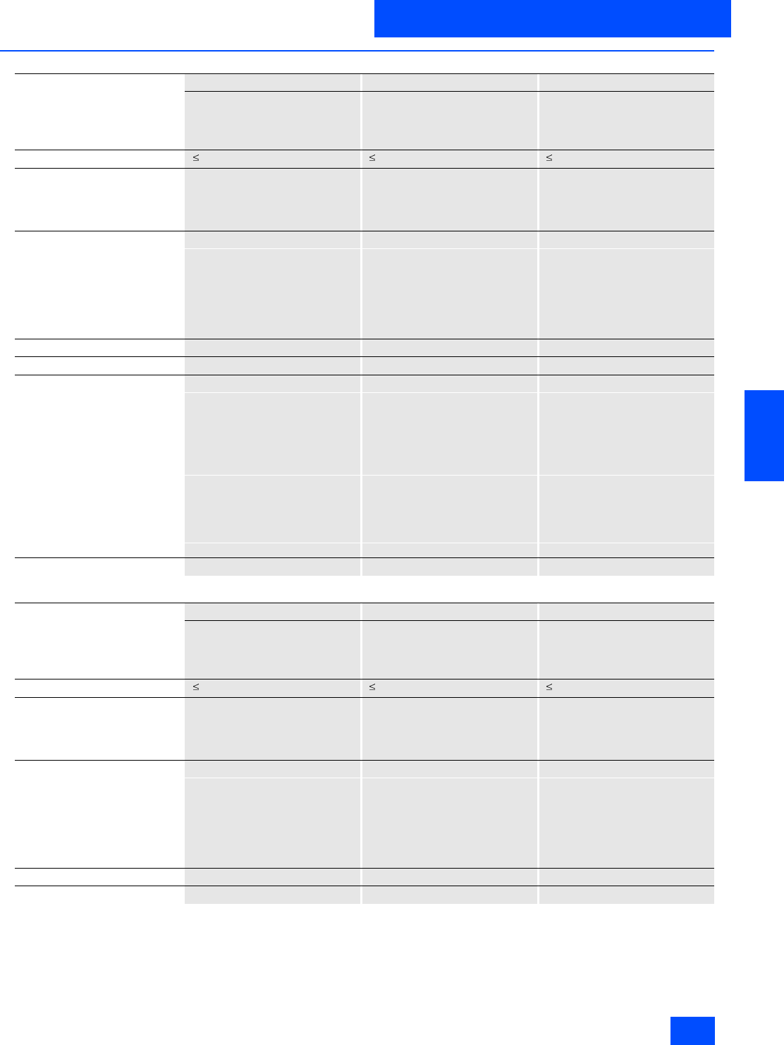
Siemens IK PI · 2004 6/45
AS-Interface Slaves
I/O modules for operation in the field
Digital I/O modules IP67 - K60
6
■
Technical specifications (continued)
4 inputs/4 outputs 4 inputs/4 outputs 4 inputs/4 outputs
2 A 2 A 1 A
Standard slaves Standard slaves Standard slaves
Y-II assignment Standard assignment Y-II assignment
3RK1 400–1DQ00–0AA3 3RK1 400–1CQ00–0AA3 3RK1 400–1DQ00–0AA3
Total current input in mA 270 270 270
Socket assignment, inputs PIN 1 = Sensor supply L+
PIN 2 = Data input II
PIN 3 = Sensor supply L-
PIN 4 = Data input I
PIN 5 = Earth connection
PIN 1 = Sensor supply L+
PIN 2 = Data input I
PIN 3 = Sensor supply L-
PIN 4 = Data input I
PIN 5 = Earth connection
PIN 1 = Sensor supply L+
PIN 2 = Data input II
PIN 3 = Sensor supply L-
PIN 4 = Data input I
PIN 5 = Earth connection
Outputs
• Current carrying capacity per
output in A DC 12 / DC 13 typ. 2 2 1
• Maximum summation current
per module in A 4 4 4
• Socket assignment, outputs 3 = "-"
2/4 = Output
5 = Ground connection
3 = "-"
4 = Output
5 = Ground connection
3 = "-"
2/4 = Output
5 = Ground connection
I/O configuration 7 7 7
ID/ID2 code F/F 0/F F/F
Assignment of data bits
• Socket 1 PIN4 = IN1 (D0)
PIN2 = IN2 (D1) PIN2/4 = IN1(D0) PIN4 = IN1 (D0)
PIN2 = IN2 (D1)
• Socket 2 PIN4 = IN2(D1) PIN2/4 = IN2(D1) PIN4 = IN2(D1)
• Socket 3 PIN4 = IN3 (D2)
PIN2 = IN4 (D3) PIN2/4 = IN3(D2) PIN4 = IN3 (D2)
PIN2 = IN4 (D3)
• Socket 4 PIN4 = IN4(D3) PIN2/4 = IN4(D3) PIN4 = IN4(D3)
• Socket 5 PIN4 = OUT1 (D0)
PIN2 = OUT2 (D1) PIN4 = OUT1(D0) PIN4 = OUT1 (D0)
PIN2 = OUT2 (D1)
• Socket 6 PIN4 = OUT2(D1) PIN4 = OUT2(D1) PIN4 = OUT2(D1)
• Socket 7 PIN4 = OUT3(D2)
PIN2 = OUT4(D3) PIN4 = OUT3(D2) PIN4 = OUT3(D2)
PIN2 = OUT4(D3)
• Socket 8 PIN4 = OUT4(D3) PIN4 = OUT4(D3) PIN4 = OUT4(D3)
Number of I/O sockets 8 8 8
4 inputs/4 outputs 4 inputs/ 3 outputs 4 inputs/2 outputs
1 A 2 A 2 A
Standard slaves A/B slaves Standard slaves
Standard assignment Y-II assignment Y-II assignment
3RK1 400–1DQ03–0AA3 3RK2 400–1FQ03–0AA3 3RK1 400–1MQ00–0AA3
Total current input in mA 270 270 270
Socket assignment, inputs PIN 1 = Sensor supply L+
PIN 2 = Data input I
PIN 3 = Sensor supply L-
PIN 4 = Data input I
PIN 5 = Earth connection
PIN 1 = Sensor supply L+
PIN 2 = Data input II
PIN 3 = Sensor supply L-
PIN 4 = Data input I
PIN 5 = Earth connection
PIN 1 = Sensor supply L+
PIN 2 = Data input II
PIN 3 = Sensor supply L-
PIN 4 = Data input I
PIN 5 = Earth connection
Outputs
• Current carrying capacity per
output in A DC 12 / DC 13 typ. 1 2 2
• Maximum summation current
per module in A 4 4 4
• Socket assignment, outputs 3 = "-"
4 = Output
5 = Ground connection
3 = "-"
2/4 = Output
5 = Ground connection
3 = "-"
2/4 = Output
5 = Ground connection
I/O configuration 7 7 7
ID/ID2 code 0/F A/2 F/F
Siemens IK PI · 2004
6/46
AS-Interface Slaves
Digital I/O modules IP67 - K60
I/O modules for operation in the field
6
■
Technical specifications (continued)
4 inputs/4 outputs 4 inputs/ 3 outputs 4 inputs/2 outputs
1 A 2 A 2 A
Standard slaves A/B slaves Standard slaves
Standard assignment Y-II assignment Y-II assignment
3RK1 400–1DQ03–0AA3 3RK2 400–1FQ03–0AA3 3RK1 400–1MQ00–0AA3
Assignment of data bits
• Socket 1 PIN2/4 = IN1(D0) PIN4 = IN1 (D0)
PIN2 = IN2 (D1) PIN4 = IN1 (D0)
PIN2 = IN2 (D1)
• Socket 2 PIN2/4 = IN2(D1) PIN4 = IN2(D1) PIN4 = IN2(D1)
• Socket 3 PIN2/4 = IN3(D2) PIN4 = IN3 (D2)
PIN2 = IN4 (D3) PIN4 = IN3 (D2)
PIN2 = IN4 (D3)
• Socket 4 PIN2/4 = IN4(D3) PIN4 = IN4(D3) PIN4 = IN4(D3)
• Socket 5 PIN4 = OUT1(D0) PIN4 = OUT1 (D0)
PIN2 = OUT2 (D1) PIN4 = OUT1 (D0)
PIN2 = OUT2 (D1)
• Socket 6 PIN4 = OUT2(D1) PIN4 = OUT2(D1) PIN4 = OUT2(D1)
• Socket 7 PIN4 = OUT3(D2) PIN4 = OUT3(D2) Unassigned (sealed)
• Socket 8 PIN4 = OUT4(D3) Unassigned (sealed) Unassigned (sealed)
Number of I/O sockets 8 7 6
4 inputs 2 x 2 inputs / 2 x 2 outputs 4 outputs
-- 1 amp 2 amps
Standard slaves Standard slaves Standard slaves
Y-II assignment Y assignment Y-II assignment
3RK1 200–0CQ00–0AA3 3RK1 400–1DQ02–0AA3 3RK1 100–1CQ00–0AA3
Total current input in mA 270 270 270
Socket assignment, inputs PIN 1 = Sensor supply L+
PIN 2 = Data input II
PIN 3 = Sensor supply L-
PIN 4 = Data input I
PIN 5 = Earth connection
PIN 1 = Sensor supply L+
PIN 2 = Data input II
PIN 3 = Sensor supply L-
PIN 4 = Data input I
PIN 5 = Earth connection
--
Outputs
• Current carrying capacity per
output in A DC 12 / DC 13 typ. -- 1 2
• Maximum summation current
per module in A -- 4 4
• Socket assignment, outputs -- 3 = "-"
2/4 = Output
5 = Ground connection
3 = "-"
2/4 = Output
5 = Ground connection
I/O configuration 0 7 8
ID/ID2 code 1/F F/F 1/F
Assignment of data bits
• Socket 1 PIN4 = IN1 (D0)
PIN2 = IN2 (D1) PIN4 = IN1 (D0)
PIN2 = IN2 (D1) --
• Socket 2 PIN4 = IN2(D1) Unassigned (sealed) --
• Socket 3 PIN4 = IN3 (D2)
PIN2 = IN4 (D3) PIN4 = IN3 (D2)
PIN2 = IN4 (D3) --
• Socket 4 PIN4 = IN4(D3) Unassigned (sealed) --
• Socket 5 Unassigned (sealed) PIN4 = OUT1 (D0)
PIN2 = OUT2 (D1) PIN4 = OUT1 (D0)
PIN2 = OUT2 (D1)
• Socket 6 Unassigned (sealed) Unassigned (sealed) PIN4 = OUT2(D1)
• Socket 7 Unassigned (sealed) PIN4 = OUT3(D2)
PIN2 = OUT4(D3) PIN4 = OUT3(D2)
PIN2 = OUT4(D3)
• Socket 8 Unassigned (sealed) Unassigned (sealed) PIN4 = OUT4(D3)
Number of I/O sockets 4 4 4

Siemens IK PI · 2004 6/47
AS-Interface Slaves
I/O modules for operation in the field
Digital I/O modules IP67 - K60
6
■
Technical specifications (continued)
K60 mounting plate Hub
For wall mounting For rail mounting --
3RK1 901-0CA00 3RK1 901-0CB00 3RK1 901-1NN00
Ambient temperature in °C -40 to +85 -40 to +85 -40 to +85
Protection IP67 with K60 compact module
screwed on IP67 with K60 compact module
screwed on IP65 with upper part screwed on
Connection technique For shaped AS-Interface cable,
contacted through the insulation-
piercing terminals integral to the
compact module
For shaped AS-Interface cable,
contacted through the insulation-
piercing terminals integral to the
compact module
For yellow or black, shaped
AS-Interface cable
contacted through the insulation-
piercing terminals integral to the
upper part
Mounting • Wall mounting
• On shaped bracket (the corre-
sponding slide rings are re-
quired)
• Hole spacing is compatible to
K45 mounting plate for wall
mounting
• Standard rail mounting • Standard mounting rail/wall
mounting
• On shaped bracket (the corre-
sponding slide rings are re-
quired)
• Hole spacing also compatible to
coupling module FK/FK-E
(application module)
Note Additional seals are only
necessary when the flat cables
terminate inside the module
(3RK1 902-0AR00)
Additional seals are only
necessary when the flat cables
terminate inside the module
(3RK1 902-0AR00)
Standard rail adapter can be
ordered separately as spare parts:
3RX1 660-0B
Distributors can be used for the
following purposes:
• Configuration of network struc-
tures (branch function)
• Isolation of cable segments
(isolating function)
• Sealing cable ends inside the
module (sealing function)
If one or both cables terminate in
the module, seals are required
(straight and shaped) that can
be inserted in the lower part of the
distributor. These seals are not
included in the scope of supply
and must be ordered separately
(3RK1 902-0AR00).
If both cables are routed into and
out of the module, additional seals
are not required.
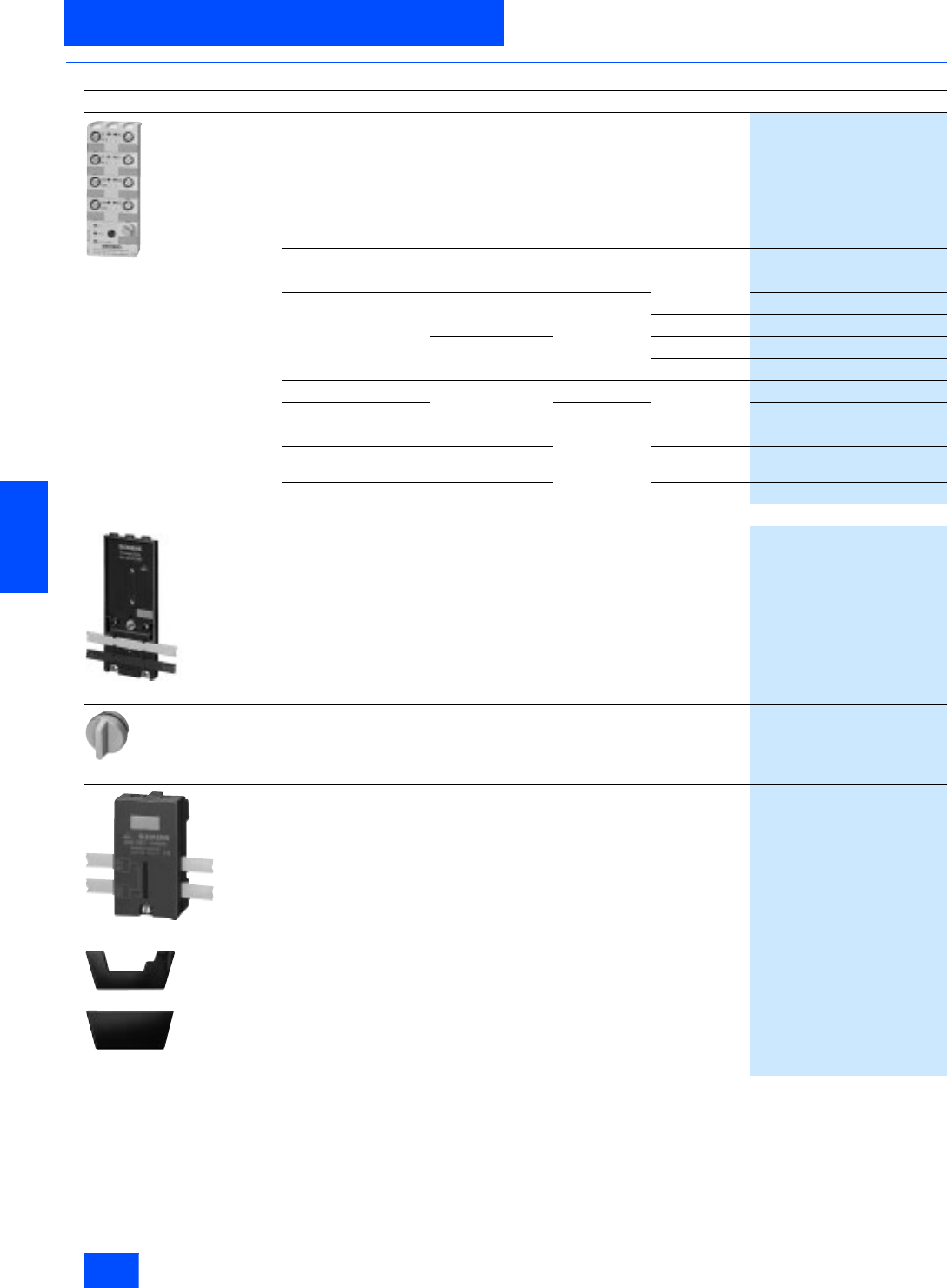
Siemens IK PI · 2004
6/48
AS-Interface Slaves
Digital I/O modules IP67 - K60
I/O modules for operation in the field
6
■
Selection and Ordering data
Design
Order No.
3RK1 400-1DQ00-0AA3
Digital I/O modules IP67 - K60
PNP transistor
Current loading capacity of inputs: 200 mA
Connection type: M12
Modules supplied without mounting plate.
Type Current loading
capacity of outputs Slave type Pin
assignments
8 Inputs/2 Outputs 2 A A/B special
3RK2 400-1HQ00-0AA3
8 Inputs –Standard Y-II
3RK1 200-0DQ00-0AA3
A/B
3RK2 200-0DQ00-0AA3
4 Inputs/4 Outputs 2 A Standard
3RK1 400-1DQ00-0AA3
Standard
3RK1 400-1CQ00-0AA3
1 A Y-II
3RK1 400-1DQ01-0AA3
Standard
3RK1 400-1DQ03-0AA3
4 Inputs/3 Outputs 2 A A/B Y-II
3RK2 400-1FQ03-0AA3
4 Inputs/2 Outputs Standard
3RK1 400-1MQ00-0AA3
4 Inputs –
3RK1 200-0CQ00-0AA3
2 x 2 Inputs/
2 x 2 Outputs 1 A Y
3RK1 400-1DQ02-0AA3
4 Outputs 2 A Y-II
3RK1100-1CQ00-0AA3
Accessories
3RK1 901-0CA00
K60 mounting plate
To fit all K60 compact modules
• Wall mounting
3RK1 901-0CA00
• Mounting onto standard rails
3RK1 901-0CB00
3RK1 901-1KA00
AS-Interface M12 sealing caps
For spare M12 sockets
(one packing contains ten sealing caps)
3RK1 901-1KA00
3RK1 901-1NN00
Distributor
For AS-Interface flat cable
Supplied with a special mounting plate
Seals (3RK1 902-0AR00) are only necessary when a cable must end
in the distributor and they must be ordered separately
3RK1 901-1NN00
3RK1 902-0AR00
Sealing kit
For K60 mounting plate and distributor
Cannot be used for K45 mounting plate
(one set contains five straight and five shaped seals)
3RK1 902-0AR00
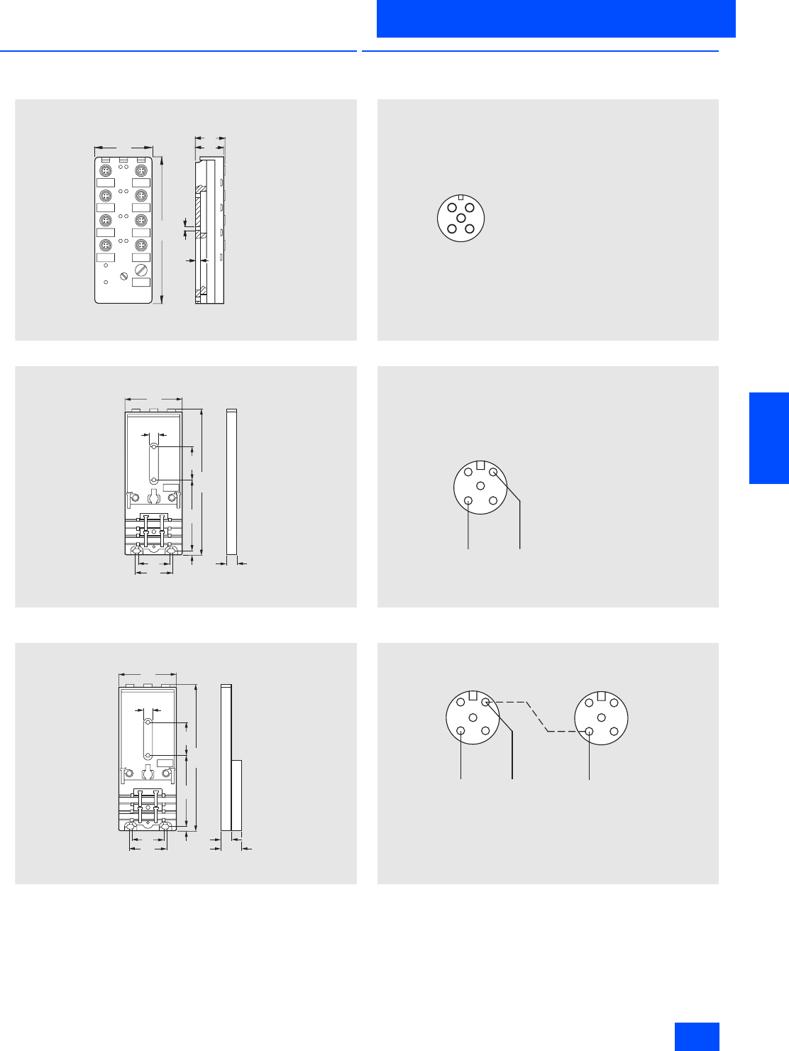
Siemens IK PI · 2004 6/49
AS-Interface Slaves
I/O modules for operation in the field
Digital I/O modules IP67 - K60
6
■
Dimensional drawings
I/O module
Mounting plate for wall mounting
3RK1 901-0CA00
Mounting plate for rail mounting
3RK1 901-0CB00
■
Schematics
Terminal assignment, input, pnp (M12 socket)
Standard assignment
Y assignment
Y-II assignment
N S A 0 _ 0 0 0 2 6
Æ
4 , 5
3 1
2 9
5
1 5 2
6 0
S i d e v i e w w i t h
m o u n t i n g p l a t e
3 R K 1 9 0 1 - 0 C A 0 0
N S A 0 _ 0 0 0 2 7 a
7 3
4 , 5
6 0
3 3
3 9
152 3 4
9
1 0
N S A0_00180
7 3
4 , 5
6 0
3 3
3 9
1 5 2 3 4
9
1 02 0
3
2
4
1
N S A 0 _ 0 0 0 0 6 a
5
P i n 1 : S u p p l y L +
P i n 2 : I n p u t s i g n a l ( b r i d g e d w i t h P i n 4 )
P i n 3 : S u p p l y L
P i n 4 : I n p u t s i g n a l ( b r i d g e d w i t h P i n 2 )
P i n 5 : E a r t h c o n n e c t i o n
N S A 0 _ 0 0 0 0 8 a
1 2
4 3
5
Y c a b l e / s i n g l e c a b l e
P i n 1 : S u p p l y L +
P i n 2 : I n p u t s i g n a l 2
P i n 3 : S u p p l y L
P i n 4 : I n p u t s i g n a l 1
P i n 5 : E a r t h c o n n e c t i o n
N S A 0 _ 0 0 0 1 0 a
1 2
4 3
5
1 2
4 3
5
Y c a b l e / S i n g l e c a b l e S i n g l e c a b l e
P i n 1 : S u p p l y L +
P i n 2 : I n p u t s i g n a l 2
P i n 3 : S u p p l y L
P i n 4 : I n p u t s i g n a l 1
P i n 5 : E a r t h c o n n e c t i o n
L e f t c o l u m n ( p l a n v i e w ) R i g h t c o l u m n ( p l a n v i e w )
P i n 1 :
S u p p l y
L +
P i n 2 :
P i n 3 :
S u p p l y
L
P i n 4 :
I n p u t s i g n a l
2
P i n 5 :
E a r t h c o n n e c t i o n
I N 1 I N 2 I N 2
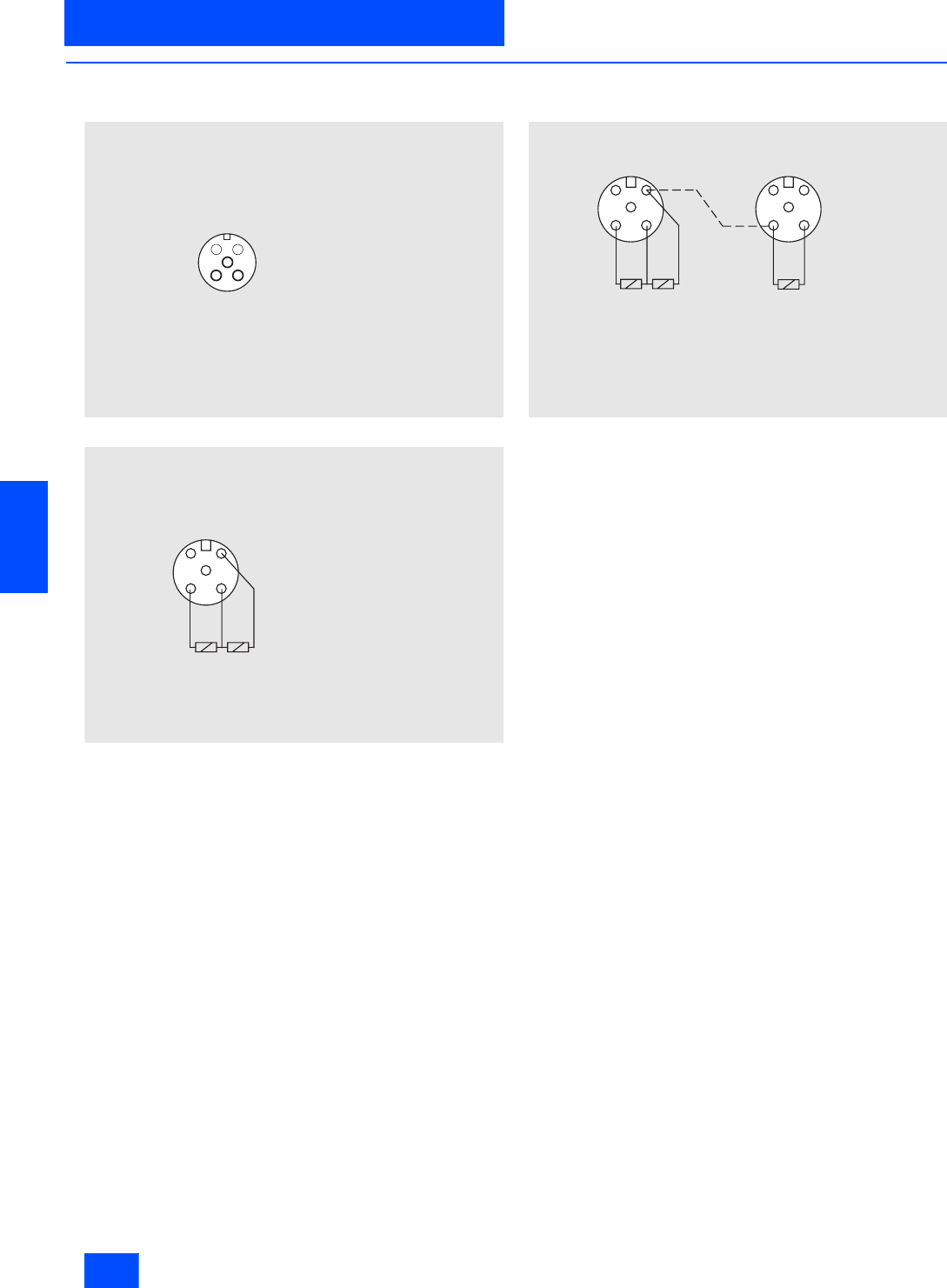
Siemens IK PI · 2004
6/50
AS-Interface Slaves
Digital I/O modules IP67 - K60
I/O modules for operation in the field
6
■
Schematics (continued)
Terminal assignment, output, pnp (M12 socket)
Standard assignment
Y assignment
Y-II assignment
3
2
4
1
N S A 0 _ 0 0 0 0 7 a
5
P i n 1 : n o t a s s i g n e d
P i n 2 :
n o t a s s i g n e d
P i n 3 : S u p p l y L
P i n 4 : O u t p u t s i g n a l
P i n 5 : E a r t h c o n n e c t i o n
1 2
4 3
5
N S A 0 _ 0 0 0 0 9 a
P i n 1 :
P i n 2 : O u t p u t s i g n a l 2
P i n 3 : S u p p l y L
P i n 4 : O u t p u t s i g n a l 1
P i n 5 : E a r t h c o n n e c t i o n
N S A 0 _ 0 0 0 1 1
1 2
4 3
5
1 2
4 3
5
S i n g l e c a b l e
P i n 1 :
P i n 2 : O u t p u t s i g n a l 2
P i n 3 : S u p p l y L
P i n 4 : O u t p u t s i g n a l 1
P i n 5 : E a r t h c o n n e c t i o n
L e f t c o l u m n ( p l a n v i e w ) R i g h t c o l u m n ( p l a n v i e w )
P i n 1 :
P i n 2 :
P i n 3 : S u p p l y L
P i n 4 : O u t p u t s i g n a l 2
P i n 5 : E a r t h c o n n e c t i o n
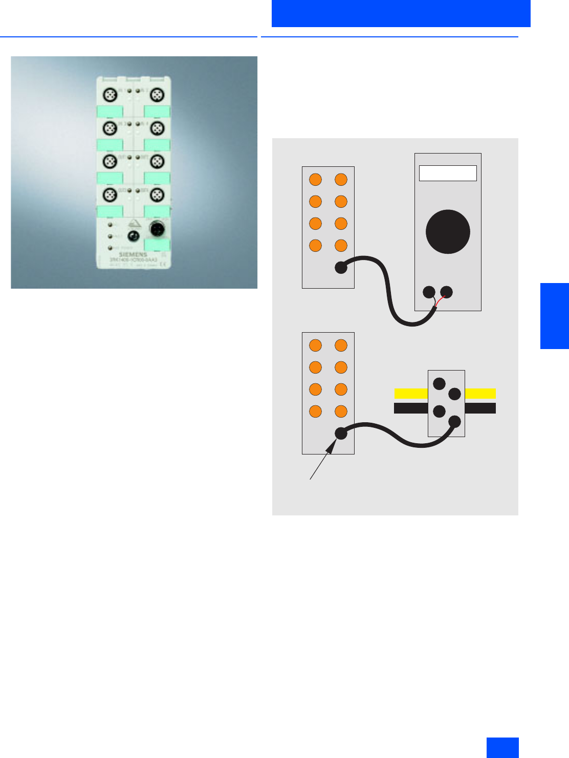
Siemens IK PI · 2004 6/51
AS-Interface Slaves
I/O modules for operation in the field
Digital I/O modules IP68 / IP69K - K60R
6
■
Overview
Modules with the degree of protection IP67 cannot be used in
environments with permanently high humidity, with drilling emul-
sions and cutting oils or for cleaning with high-pressure clean-
ers. For these applications, the extension for the K60 compact
modules, the K60R module with degree of protection IP68 /
IP69K, is the solution.
The K60R modules are connected via a round cable with a M12
cable plug instead of the AS-Interface ribbon cable.
The AS-Interface bus cable and 24 V DC auxiliary power are
routed in a common round cable.
The degree of protection IP68 permits many new areas of appli-
cations for which the previous field modules with degree of pro-
tection IP67 could not be used. The K60R with degree of protec-
tion IP68 makes it possible to use the module for applications
such as bottling plants or machine tools on-site in areas sub-
jected to permanently high humidity. This allows the savings in
wiring outlay due to AS-Interface to be implemented with even
greater consistency. For IP68 test conditions see Section
Tests IP68 / IP69K.
Cleaning with pressurized cleaning equipment, as is frequently
necessary in the food, beverages and tobacco industries, is
problem-free (IP69K).
When trailing cables are used, many users require that the AS-
Interface bus cable is routed in a round cable. The K60R module
permits direct connection to a round cable. An adapter is not re-
quired.
■
Design
Mounting
The same mounting plates are used as for the K60 modules.
The K60R is connected using a 4-conductor round cable with an
M12 connection instead of using ribbon cables. The mounting
plate therefore only serves for the K60R as a mounting point and
grounding connection.
Addressing
Addressing is carried out using the same socket as for the bus
connection. The connection of the module to the addressing unit
3RK1 904-2AB01 is carried out with a standard M12 cable
(e.g. 3RX1 642). A special addressing line (3RK1901-3RA00) is
required when using the older version of the addressing unit
3RK1 904-2AB00. Following mounting, the module is connected
to the addressing unit using the addressing line, and then
addressed. The addressing line is subsequently removed, and
the module connected to the bus cable.
NSA0_00338
Socket for bus connection and addressing
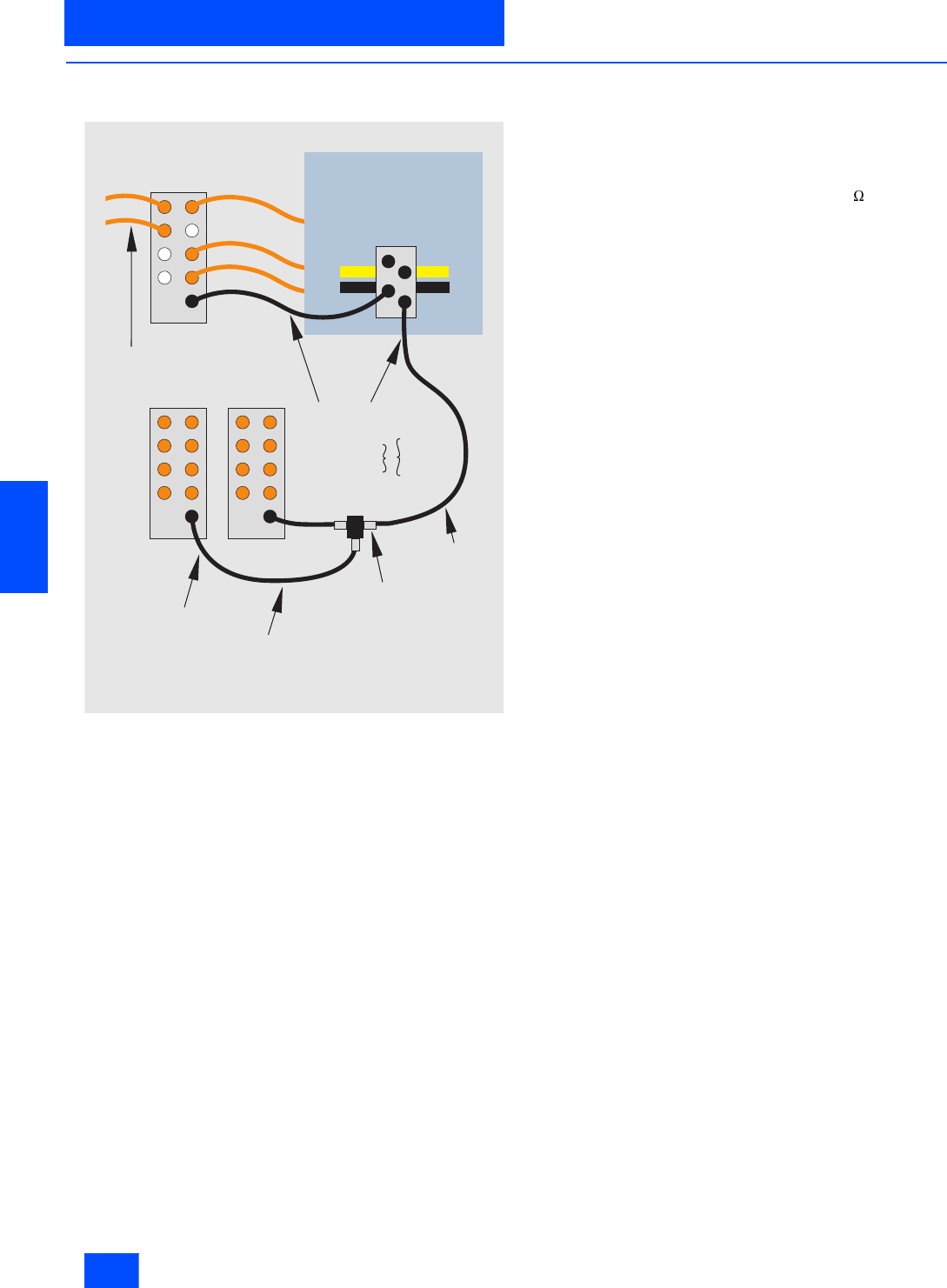
Siemens IK PI · 2004
6/52
AS-Interface Slaves
Digital I/O modules IP68 / IP69K - K60R
I/O modules for operation in the field
6
■
Design (continued)
Connection
In the IP67 environment, the proven standard components are
connected using ribbon cables. Branch lines are made into
the IP68 environment via a round cable distributor (3RK1901-
1NR00). The module is connected using a round cable with M12
socket. The module has an M12 bus connection for this instead
of the previous addressing socket. The AS-Interface bus cable
and the 24 V DC power supply are routed together in a 4-con-
ductor round cable. This round cable must not have an earthing
conductor. The earthing connection is made via the mounting
plate.
Only cables with molded M12 plugs may be used in the IP68 en-
vironment. This cable is available as a preassembled M12 cable
plug/socket:
• 3RX1641: 0.5 m long
• 3RX1640: 1.0 m long
• 3RX1642: 1.5 m long
Freely-assembled cables with an M12 cable socket and a free
cable end can be used for the connection between the distribu-
tor and K60R module over longer distances, where the free end
is fitted with an M12 plug (straight version: 3RX1586, angled
plug 3RX1587) and connected to the distributor. This cable is
available in two versions:
• 3RX1536: 5 m long, with M12 cable socket
• 3RX1542: 5 m long, with M12 angled cable socket
If more than one K60R module is to be connected to a branch
line, this can be distributed further using a T-distributor
(3RK1901-1TR00) in degree of protection IP68.
The following conditions must be observed: The design guide-
lines for the AS-Interface are applicable. The maximum permis-
sible current is limited to 4 A for all M12 connection cables.
The cross-section of these cables is only 0.34 mm². The M12
connection cables mentioned (max. length 5 m) can be used for
the branch lines to connect the K60R modules. The voltage drop
resulting from the ohmic resistance (approx. 0.11 /m) must be
taken into account. The total maximum load for all four connec-
tions of the round cable distributor 3RK1901-1NR00 is 4 A.
In applications with only round cables, the AS-Interface bus ca-
ble and the 24 V DC power supply can be routed together up to
20 m when using a round cable 4 x 1.5 mm². With longer cables,
routing is made using two separate cables of 2 x 1.5 mm² each.
A round cable distributor (3RK1901-1NR00) is not required for
such applications. Distribution to the K60R modules is then
made using a terminal box and the M12 cables referred to.
IP68 / IP69K tests
K60R modules are tested as follows:
•Extra testing compared to IP67: 90 min under 1.8 m water
(IP67: 30 min under 1 m water)
•Salt water test: five months immersed in salt water, 20 cm deep
at room temperature
•Test with particularly creeping oil: five months completely un-
der oil at room temperature
•Test with drilling emulsion: five months at room temperature
(components of drilling emulsion: anionic and non-ionic emul-
sifiers, paraffinic low-aromatic mineral oil, boric acid alkanola-
mines, corrosion inhibitors, oil content 40 %)
•Test in oil bath (Oil Excellence 416) with changing oil tempera-
ture: 130 cycles from 15 to 55 °C, two months
•Cleaning with high-pressure cleaner according to IP69K:
80 to 100 bar, distance 10 to 15 cm, time per side > 30 s, water
temperature 80 °C
In order to simulate demands which are as realistic as possible,
the modules have been artificially aged prior to the tests by 15
temperature cycles of -25/+85 °C. The modules were connected
by 3RX1 cables during the tests. Unused connections were
closed by sealing caps 3RK1901-1KA00.
Note: Sealing caps and M12 connections must be tightened with
the correct torque.
3RX1 9 01 1NRO
NSA0_00339
IP68
3RX1 672 (5 m)
3RX1 674 (5 m)
3RX1 641 (0,5 m)
3RX1 640 (1,0 m)
3RX1 642 (1,5 m) max. 1,5 m
max. 5 m
3RK1 901-1TR00
3RX1 641 (0,5 m)
3RX1 640 (1,0m)
3RX1 642 (1,5 m)
3RX1 536 (5 m)
3RX1 542 (5 m)
+
connector
3RX1 586
3RX1 587
IP67

Siemens IK PI · 2004 6/53
AS-Interface Slaves
I/O modules for operation in the field
Digital I/O modules IP68 / IP69K - K60R
6
■
Technical specifications
4 inputs/4 outputs IP68 / IP69K
Standard assignment
3RK1 400–1CR00–0AA3
Slave type Standard slaves
Operational voltage in accordance
with AS-Interface specification in V 26.5 to 31.6
Total current input in mA 270
Input connection PNP
Inputs
• Sensor supply via AS-Interface Short-circuit and overload proof
•Sensors 2- and 3-wire
• Voltage range in V 20 to 30
• Current carrying capacity for all in-
puts
(Tu 40 °C) in mA
200
• Switching level High in V 10
• Input current Low/High in mA 1.5 / 6
• Pin assignments for inputs PIN 1 = Sensor supply L+
PIN 2 = Data input I
PIN 3 = Sensor supply L-
PIN 4 = Data input I
PIN 5 = Ground connection
Outputs
• Type of output Electronics
• Current carrying-capacity
DC 12/13 typically
(max. 4 A per module) in A
2
• Maximum summation current
per module in A 4
• Pin assignments for outputs 3 = „-“
4 = Output
5 = Earth connection
• Short-circuit protection built-in
• Inductive interference protection built-in
• External voltage supply
DC 24 V Shared round cable connection
with AS-Interface connection via
M12 socket connector
• Watchdog built-in
I/O configuration 7
ID/ID2 code 0/F
Assignment of data bits
• Socket 1 (data bit D0) PIN2/4 = IN1(D0)
• Socket 2 (data bit D1) PIN2/4 = IN2(D1)
• Socket 3 (data bit D2) PIN2/4 = IN3(D2)
• Socket 4 (data bit D3) PIN2/4 = IN4(D3)
• Socket 5 (data bit D0) PIN4 = OUT1(D0)
• Socket 6 (data bit D1) PIN4 = OUT2(D1)
• Socket 7 (data bit D2) PIN4 = OUT3(D2)
• Socket 8 (data bit D3) PIN4 = OUT4(D3)
4 inputs/4 outputs IP68 / IP69K
Standard assignment
3RK1 400–1CR00–0AA3
AS-Interface certificate Yes
Approvals UL, CSA, ship building
Degree of protection IP68 / IP69K with mounting plate
3RK1 901-0CA00
IP68 test conditions see Section
Overview / Tests IP68 / IP69K
The degree of protection is only
achieved if all M12 connections
are tightened with the correct
torque. I/O sockets which are not
required must be covered with
sealing caps 3RK1 901-1KA00.
Earth connection PIN5 of each M12 socket is
connected to the grounding plate
in the mounting plate via a pin.
Ambient temperature in °C -25 to +85
Storage temperature in °C -40 to +85
Number of I/O sockets 8
Status indications
• I/O indication Yellow LED
• IndicationUHelp Green LED
• AS-Interface/diagnostics
indication Green/red LED
Conductor via mounting plate for K60
compact module
Note 1 All K60 compact modules are
supplied with stainless steel
screws/sockets
Note 2 To supply the output circuit,
an external supplementary
supply (AUX POWER)
of 20 to 30 V DC is necessary.
The supplementary supply must
comply with VDE 0106 (PELV),
safety class III.
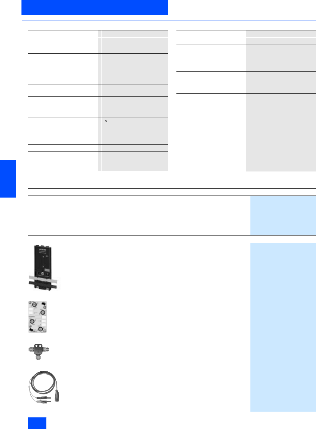
Siemens IK PI · 2004
6/54
AS-Interface Slaves
Digital I/O modules IP68 / IP69K - K60R
I/O modules for operation in the field
6
■
Technical specifications (continued)
■
Selection and Ordering data
IP67 round cable distributor
AS-i / Uaux Ribbon cable for
4 x M12, passive without LED
3RK1 901–1NR00
Function Connection of K60R modules to
AS-Interface ribbon cable in IP-67
environment
Operating voltage in V 26.5 to 31.6 DC (AS-Interface)
Voltage range in V 20 to 30 DC
Total current carrying capacity for
all distributors in A 4
Socket assignment 1 = AS-i "+"
2 = Uaux "-"
3 = AS-i "–"
4 = Uaux "+"
Conductor 4 M12 socket for connection to
AS-Interface (sensors/actuators)
Degree of protection IP67
Ambient temperature in °C –25 to +85
Storage temperature in °C –40 to +85
Number of M 12 sockets 4
Connection via contact pins on FCI coupling
module (in scope of delivery)
M12-T distributor
3RK1 901–1TR00
Function for connecting several K60R to
one M12 spur line
Voltage range in V 20 to 30 DC
Current-carrying capacity in A 4 at T = 40 °C
Conductor M12
Degree of protection IP68
Ambient temperature in °C -25 to +85
Storage temperature in °C -25 to +85
Number of M 12 sockets 1 x M12 connector /
2 x M12 sockets
Design
Order No.
4 inputs/4 outputs 1)
IP68 / IP69K
Standard assignment
Current carrying capacity:
200 mA (inputs)
2 A (outputs)
Standard slave
Delivery of modules is without mounting plate
3RK1 400-1CR00-0AA3
Accessories
3RK1 901-0CA00
Mounting plate K60
appropriate for all K60 and K60R compact modules
• Wall mounting
3RK1 901-0CA00
• Onto standard rails
3RK1 901-0CB00
3RK1 901-1NR00
Round cable distributor IP67
4-way AS-i/Uaux
Ribbon cable to 4 x M12
Current carrying capacity: 4 A
Passive without LED
Scope of delivery including coupling module
3RK1 901-1NR00
3RK1 901-1TR00
M12 T-distributor
IP68
1 x M12 plug
2 x M12 socket
3RK1 901-1TR00
3RK1 901-3RA00
Addressing cable M12
for addressing K60R modules
(only required for addressing unit 3RK1 904-2AB00;
when using the latest version of the addressing unit 3RK1 904-2AB01,
the addressing is carried out with a standard M12 cable 3RX1 642)
3RK1 901-3RA00
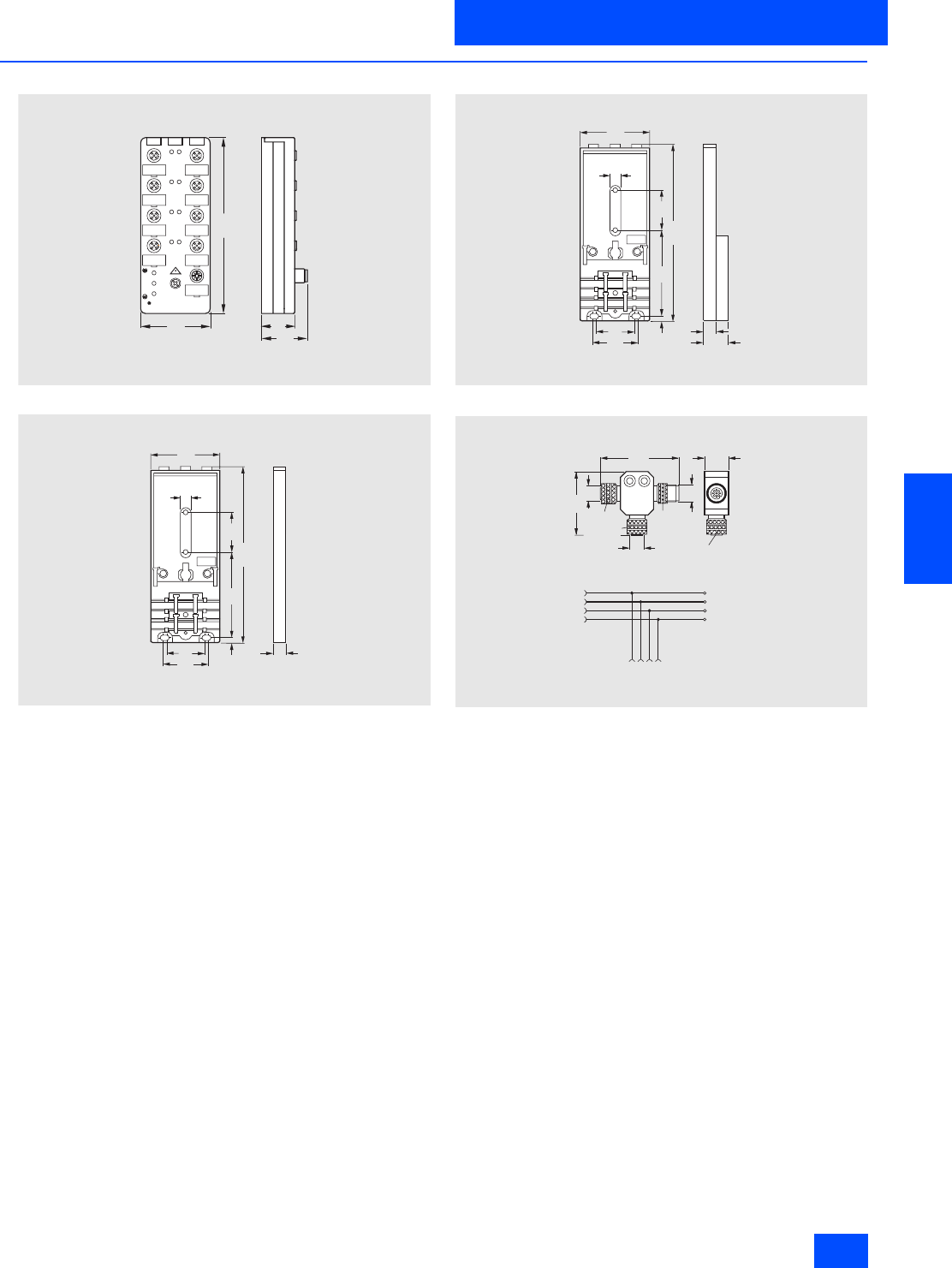
Siemens IK PI · 2004 6/55
AS-Interface Slaves
I/O modules for operation in the field
Digital I/O modules IP68 / IP69K - K60R
6
■
Dimensional drawings
I/O module
Mounting plate for wall mounting
Mounting plate for mounting onto standard rail
M12-T hub
4 0
152
N S A 0 _ 0 0 3 4 2
6 0
2 9
N S A 0 _ 0 0 0 2 7 a
7 3
4 , 5
6 0
3 3
3 9
152 3 4
9
1 0
N S A0_00180
7 3
4 , 5
6 0
3 3
3 9
1 5 2 3 4
9
1 02 0
M12x1
M12x1
M12x1
56
45
17
NSA0_00340
1
2
3
4
3
4
1
2
1234
Male
cable
plug
Fem.
cable
plug
Cover ring
Wiring diagram
4-pole
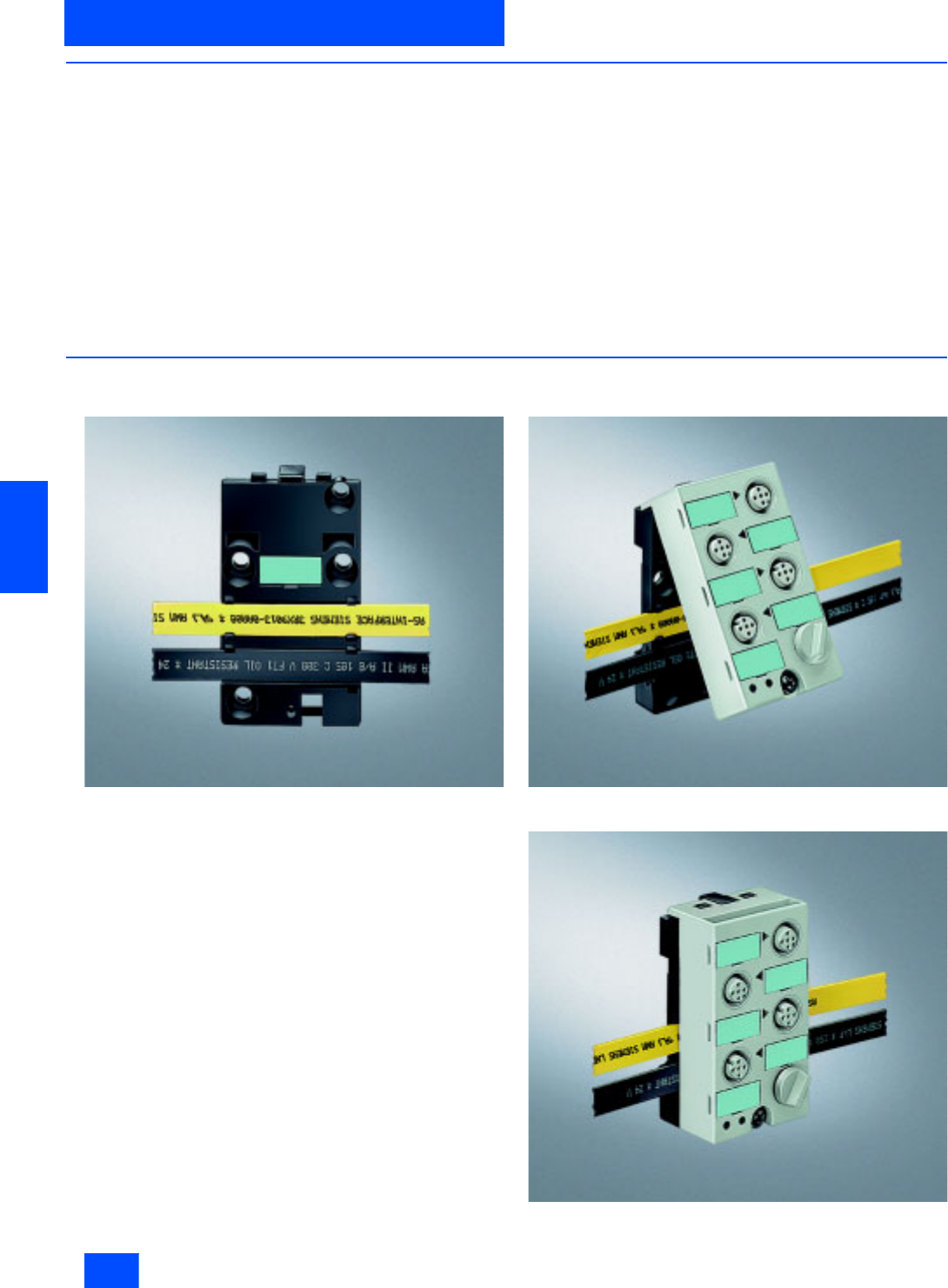
Siemens IK PI · 2004
6/56
AS-Interface Slaves
Digital I/O modules IP67 - K45
I/O modules for operation in the field
6
■
Overview
Large K60 compact modules, well-proven in industry, are now
complemented by the new K45 compact module series. They
round off the existing product spectrum at the lower end and
form the basis of a future generation of small compact modules.
The recognized advantages of the existing K60 compact
modules are entirely mirrored in the considerably smaller K45
modules. They have the same base area as the application mod-
ules, but the installed depth is only 2/3 of that of the application
modules and therefore matches the compact module family.
Despite these small dimensions, all modules feature large en-
graving plates and the integrated addressing socket.
Two mounting plates are offered for the K45 compact modules:
• The first mounting plate has the same hole pattern as the K60
compact module. This means that K60 compact modules can
be mounted flush in combination with K45 modules. The flat
cables are laid without obstructions in the special depressions
in the mounting plates.
• The second mounting plate has the drilled holes and the stan-
dard rail mounting adapter of the application modules.
Installation of the flat cables has been simplified. The yellow and
black AS-Interface® flat cable can be inserted in the mounting
plates from the left or right depending on the position of the cod-
ing lug. The polarity of the applied voltages cannot be reversed.
The sensors/actuators are connected via M12 sockets. The 4I
module can be ordered as an alternative with M 8 connection
sockets.
■
Design
Mounting
The yellow or black and yellow AS-Interface flat cables are laid in the
appropriate cable guides of the mounting plate. They can be inserted in
any direction.
The top of the module is located onto the mounting plate.
The top section is fixed to the mounting plate with just one screw.
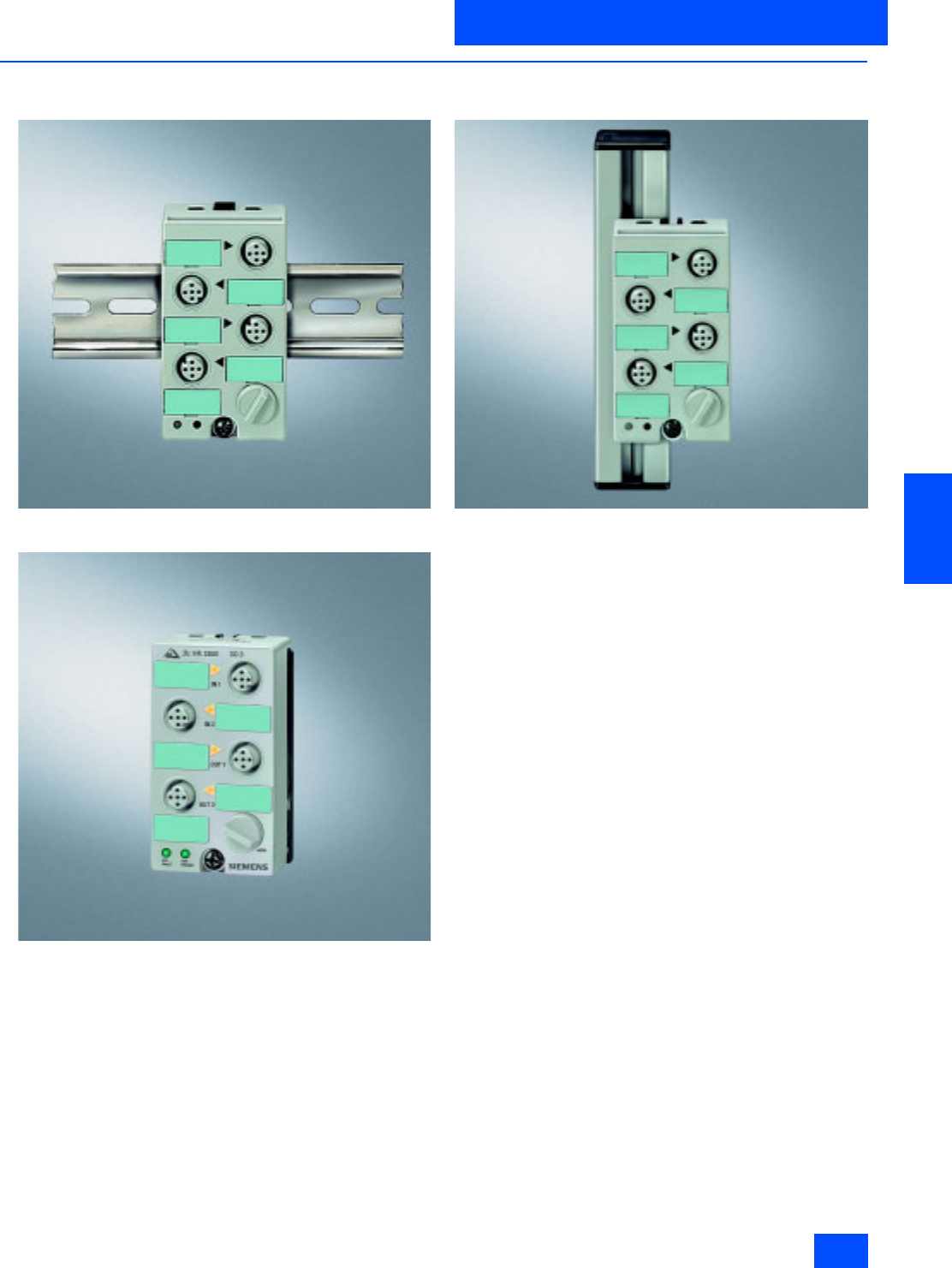
Siemens IK PI · 2004 6/57
AS-Interface Slaves
I/O modules for operation in the field
Digital I/O modules IP67 - K45
6
■
Design (continued)
Mounting possibilities
Standard rail mounting with 3RK1 901-2DA00 mounting plate.
Wall mounting with 3RK1 901-2EA00 mounting plate.
Mounting (horizontal and vertical fixing is possible) on generally available
shaped rails with screws-on slides (max. M5, not included in the scope
of supply) on mounting plate 3RK1 901-2EA00 or 3RK1 901-2DA00.
Addressing
The addresses are assigned using an integrated addressing
socket.
M12 sockets that are not required must be sealed with
3RK1 901-1KA00 blank plugs in order to guarantee the speci-
fied degree of protection.

Siemens IK PI · 2004
6/58
AS-Interface Slaves
Digital I/O modules IP67 - K45
I/O modules for operation in the field
6
■
Technical specifications
Technical specifications common to all IP67 – K45 digital I/O modules
1) for 3RK2 400-1BQ20-0AA3 Umin = 16.5 V
Operational voltage in accordance
with AS-Interface specification in V 26.5 to 31.6
Polarity reversal protection U AS-
Interface Built-in
Input connection PNP
Inputs
• Sensor supply via AS-Interface Short-circuit and overload with-
stand capability
•Sensors 2- and 3-wire
• Voltage range in V 20 to 30
• Current carrying capacity
for all inputs
(Tu 40 °C) in mA
200
• Switching level High in V 10
• Input current Low/High in mA 1.5 / 6
Outputs
• Type of output Electronics
• Short-circuit protection Built-in
• Inductive interference protection
(free-wheeling diode) Built-in
• External 24 V DC supply voltage Over black AS-Interface flat cable
• Watchdog Built-in
AS-Interface certificate Available (or under application
in the case of new products)
Approvals UL, CSA, marine certification
(or under application in the case
of new products)
Degree of protection IP67 (IP65 for M8 snap-on con-
nection)
Ground connection Through PIN5 of the M12 socket
and outgoing through a 2.8 mm
tab connector (no earth connec-
tion for M8 sockets)
Ambient temperature in °C -25 to +85
Storage temperature in °C -40 to +85
Status indications
• I/O display Yellow LED
•Display UAux Green LED
• AS-Interface/diagnostics display Dual LED, green/red
Connection Using mounting plate for K45
compact module
Note 1 All K45 compact modules are
supplied with high-grade steel
screws/sockets
Note 2 To supply the output circuit, an
external supplementary supply
(AUX POWER) of 20 to 30 V DC is
necessary. The supplementary
supply must comply with VDE
0106 (PELV), Safety Class III.
4 inputs 4 inputs 4 inputs
Standard slaves Standard slaves Standard slave
Standard assignment Standard assignment Standard assignment
M12 M8 screw connection M8 screw connection
3RK1 200–0CQ20–0AA3 3RK1 200–0CT20–0AA3 3RK1 200–0CU20–0AA3
Total current input in mA 270 270 270
Socket assignment, inputs PIN1 = Sensor supply L+
PIN3 = Sensor supply L-
PIN4 + 2 = Data input
PIN5 = Ground connection
PIN1 = Sensor supply L+
PIN3 = Sensor supply L-
PIN4 = Data input
PIN1 = Sensor supply L+
PIN3 = Sensor supply L-
PIN4 = Data input
I/O configuration 0 0 0
ID/ID2 code 0/F 0/F 0/F
Assignment of data bits
• Socket 1 PIN4/2 = IN1(D0) PIN4 = IN1(D0) PIN4 = IN1(D0)
• Socket 2 PIN4/2 = IN2(D1) PIN4 = IN2(D1) PIN4 = IN2(D1)
• Socket 3 PIN4/2 = IN3(D2) PIN4 = IN3(D2) PIN4 = IN3(D2)
• Socket 4 PIN4/2 = IN4(D3) PIN4 = IN4(D3) PIN4 = IN4(D3)
Number of I/O sockets 4 4 4
4 inputs 4 inputs 4 inputs
A/B slave A/B slaves A/B slaves
Standard assignment Standard assignment Standard assignment
M12 M8 screw connection M8 screw connection
3RK2 200–0CQ20–0AA3 3RK2 200–0CT20–0AA3 3RK2 200–0CU20–0AA3
Total current input in mA 270 270 270
Socket assignment, inputs PIN1 = Sensor supply L+
PIN3 = Sensor supply L-
PIN4 + 2 = Data input
PIN5 = Ground connection
PIN1 = Sensor supply L+
PIN3 = Sensor supply L-
PIN4 = Data input
PIN1 = Sensor supply L+
PIN3 = Sensor supply L-
PIN4 = Data input
I/O configuration 0 0 0
ID/ID2 code A/0 A/0 A/0
Assignment of data bits
• Socket 1 PIN4/2 = IN1(D0) PIN4 = IN1(D0) PIN4 = IN1(D0)
• Socket 2 PIN4/2 = IN2(D1) PIN4 = IN2(D1) PIN4 = IN2(D1)
• Socket 3 PIN4/2 = IN3(D2) PIN4 = IN3(D2) PIN4 = IN3(D2)
• Socket 4 PIN4/2 = IN4(D3) PIN4 = IN4(D3) PIN4 = IN4(D3)
Number of I/O sockets 4 4 4

Siemens IK PI · 2004 6/59
AS-Interface Slaves
I/O modules for operation in the field
Digital I/O modules IP67 - K45
6
■
Technical specifications (continued)
1) The typical current carrying capacity per output increases with Version "E12" from 1.5 to 2 A (available from approx. 07/2003).
2x2 inputs 2 inputs / 2 outputs 2 x (1 input / 1 output)
-- Current carrying capacity
of outputs: 2 A 1)Current carrying capacity
of outputs: 0.2 A
A/B slaves Standard slave Standard slaves
Y assignment Standard assignment Standard assignment
M12 M12 M12
3RK2 200–0CQ22–0AA3 3RK1 400–1BQ20–0AA3 3RK1 400–0GQ20–0AA3
Total current input in mA 270 270 270
Polarity reversal protection U Aux Not applicable Through coding U Aux not required
Socket assignment, inputs PIN1 = Sensor supply L+
PIN3 = Sensor supply L-
PIN4 + 2 = Data input
PIN5 = Ground connection
PIN1 = Sensor supply L+
PIN2 = Data input
PIN3 = Sensor supply L
PIN4 = Data input
PIN5 = Earth connection
PIN1 = Sensor supply L+
PIN2 = Output
PIN3 = Sensor supply L-
PIN4 = Data input
PIN5 = Earth connection
Outputs
• Current carrying capacity per
output in A DC 12 / DC 13 typ. -- 2 1)0,2
• Maximum summation current
per module in A -- 30,2
I/O configuration 0 3 3
ID/ID2 code A/0 0/F F/F
Assignment of data bits
• Socket 1 PIN4 = IN1 (D0)
PIN2 = IN2 (D1) PIN4/2 = IN1(D0) PIN4 = IN1(D0)
PIN2 = OUT3(D2)
• Socket 2 -- PIN4/2 = IN2(D1) --
• Socket 3 -- PIN4 = OUT3(D2) --
• Socket 4 PIN4 = IN3 (D2)
PIN2 = IN4 (D3) PIN4 = OUT4(D3) PIN4 = IN2(D1)
PIN2 = OUT3(D3)
Number of I/O sockets 2 4 2
4 outputs 3 outputs 2 outputs / 2 inputs
Current carrying capacity
of outputs: 1 A
Current carrying capacity
of outputs: 1 A
Current carrying capacity
of outputs: 2 A
Standard slaves A/B slaves A/B slave
Standard assignment Standard assignment Standard assignment
M12 M12 M12
3RK1 100–1CQ20–0AA3 3RK2 100–1EQ20–0AA3 3RK2 400–1BQ20–0AA3
Total current input in mA 45 45 270
Polarity reversal protection U Aux Through coding Through coding Through coding
Socket assignment, inputs -- -- PIN1 = Sensor supply L+
PIN2 = Data input
PIN3 = Sensor supply L
PIN4 = Data input
PIN5 = Earth connection
Outputs
• Current carrying capacity per out-
put in A DC 12 / DC 13 typ. 1 1 2
• Maximum summation current per
module in A 3 3 3
I/O configuration 8 8 B
ID/ID2 code 0/F A/0 A/0
Assignment of data bits
• Socket 1 PIN4 = OUT1(D0) PIN4 = OUT1(D0) PIN4/2 = IN3(D2)
• Socket 2 PIN4 = OUT2(D1) PIN4 = OUT2(D1) PIN4/2 = IN4(D3)
• Socket 3 PIN4 = OUT3(D2) PIN4 = OUT3(D2) PIN4 = OUT1(D0)
• Socket 4 PIN4 = OUT4(D3) Not available PIN4 = OUT2(D1)
Number of I/O sockets 4 3 4

Siemens IK PI · 2004
6/60
AS-Interface Slaves
Digital I/O modules IP67 - K45
I/O modules for operation in the field
6
■
Technical specifications (continued)
K45 mounting plate Hub Cable end piece
For wall mounting For standard rail
mounting
-- --
3RK1 901-2EA00 3RK1 901-2DA00 3RK1 901-1NN00 3RK1 901-1MN00
Ambient temperature in °C -40 to +85 -40 to +85 -40 to +85 40 to +85
Degree of protection IP67 with K45 compact
module screwed on IP67 with K45 compact
module screwed on IP65 with upper part
screwed on IP67 with shaped AS-
Interface cable inserted
Connection technique For shaped AS-Interface
cable, contacted through
the insulation-piercing ter-
minals integral to the com-
pact module
For shaped AS-Interface
cable, contacted through
the insulation-piercing ter-
minals integral to the com-
pact module
For yellow or black,
shaped AS-Interface
cable, contacted through
the insulation-piercing ter-
minals integral to the
upper part
Heavy-gauge threaded-
joint connector with inte-
grated seal (seal shaped
for AS-Interface cable)
Mounting • Wall mounting
• On shaped bracket
(the corresponding slide
rings are required)
• Hole spacing compati-
ble with K60 mounting
plate
• Standard mounting
rail/wall mounting
• On shaped bracket
(the corresponding slide
rings are required)
• Hole spacing compati-
ble to coupling module
FK/FK-E (application
module)
• Standard mounting
rail/wall mounting
• On shaped bracket
(the corresponding slide
rings are required)
• Hole spacing compati-
ble to coupling module
FK/FK-E (application
module)
Cable end piece can be
fixed, for example, to a
machine by means of
integral ring
Note The yellow and black
AS-Interface cable can
be inserted from any
direction
The yellow and black
AS-Interface cable can
be inserted from any
direction
Distributors can be
used for the following
purposes:
• Configuration of
network structures
(branch function)
• Isolation of cable
segments (isolating
function)
• Sealing cable ends
inside the module
(sealing function)
If one or both cables
terminate in the module,
seals are required
(straight and shaped)
that can be inserted in the
lower part of the distribu-
tor.
These seals are not
included in the scope
of supply and must be
ordered separately
(3RK1 902-0AR00).
If both cables are routed
into and out of the mod-
ule, additional seals are
not required.
--
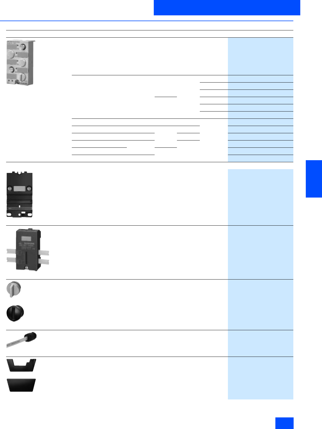
Siemens IK PI · 2004 6/61
AS-Interface Slaves
I/O modules for operation in the field
Digital I/O modules IP67 - K45
6
■
Selection and Ordering data
1) The typical current carrying capacity per output increases with Version "E12“ from 1.5 to 2 A (available from approx. 07/2003).
2) Start of delivery approx. end of 2003.
Design Order No.
3RK1 400-0GQ20-0AA3
Digital I/O modules IP67 - K45
PNP transistor
Current loading capacity of inputs: 200 mA
Modules supplied without mounting plate.
Type Current load-
ing capacity
of outputs
Slave
type Pin
assign-
ments
Connection
technique
4 inputs -- Standard Standard M12
3RK1 200-0CQ20-0AA3
M8 screws
3RK1 200-0CT20-0AA3
M8 snap-on
3RK1 200-0CU20-0AA3
A/B M12
3RK2 200-0CQ20-0AA3
M8 screws
3RK2 200-0CT20-0AA3
M8 snap-on
3RK2 200-0CU20-0AA3
2 x 2 inputs -- A/B Y M12
3RK2 200-0CQ22-0AA3
2 inputs/2 outputs 2 A 1) Standard Standard
3RK1 400-1BQ20-0AA3
2 x (1 input / 1 output) 0.2 A Y
3RK1 400-0GQ20-0AA3
4 outputs 1 A Standard
3RK1 100-1CQ20-0AA3
3 outputs A/B
3RK2 100-1EQ20-0AA3
2 outputs / 2 inputs 2) new 2 A
3RK2 400-1BQ20-0AA3
Accessories
3RK1 901-2EA00
K45 mounting plate
• For wall mounting
3RK1 901-2EA00
• For mounting onto standard rails
3RK1 901-2DA00
3RK1 901-1NN00
Distributor
For AS-Interface flat cable
Supplied inclusive of special mounting plate
Seals (3RK1 902-0AR00) are only necessary when a cable
must end in the distributor and must be ordered separately
3RK1 901-1NN00
3RK1 901-1KA00
3RK1 901-1PN00
AS-Interface sealing caps
(one set contains ten sealing caps)
• For spare M12 sockets
3RK1 901-1KA00
• For spare M8 sockets
3RK1 901-1PN00
3RK1 901-1MN00
Cable end piece
For sealing open cable ends (of the shaped AS-Interface cable) in IP67
(one set contains ten cable end pieces)
3RK1 901-1MN00
3RK1 902-0AR00
Sealing set
For K60 mounting plate and distributor
Cannot be used for K45 mounting plate
(one set contains five straight and five shaped seals)
3RK1 902-0AR00
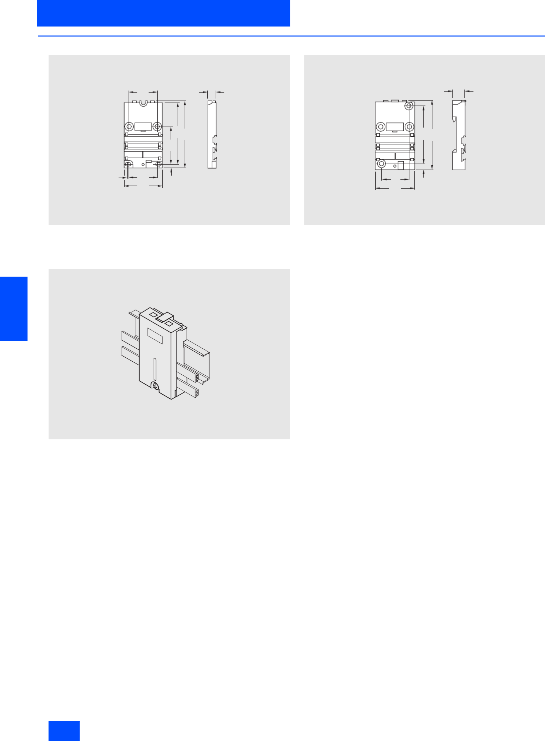
Siemens IK PI · 2004
6/62
AS-Interface Slaves
Digital I/O modules IP67 - K45
I/O modules for operation in the field
6
■
Dimensional drawings
Mounting plate for wall mounting
3RK1 901-2EA00
Drilled holes and mounting possibilities as for the K60 compact module
Mounting plate for standard rail mounting
3RK1 901-2DA00
Drilled holes and mounting possibilities as for the application module
Distributor
3RK1 901-1NN00
33
NSA00028
3
45
33
45
73
4,5
80
10
31
NSA0_00029b
45
66
7
80
14
N S A 0 _ 0 0 3 0 9
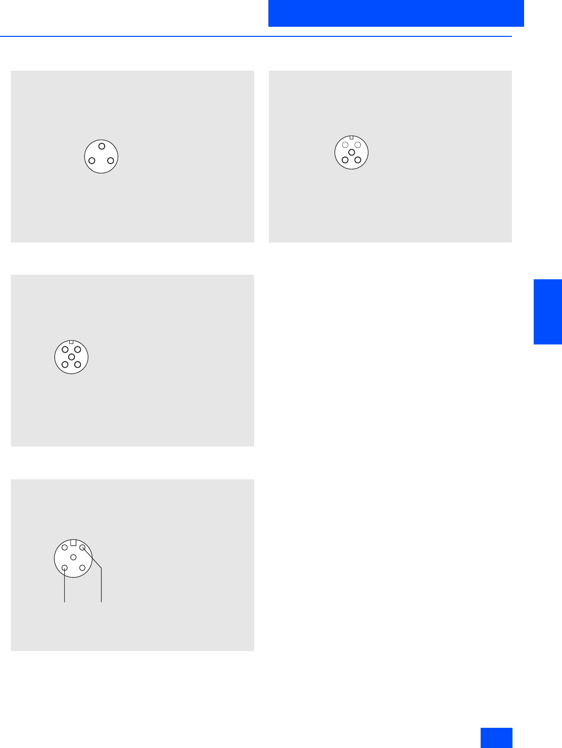
Siemens IK PI · 2004 6/63
AS-Interface Slaves
I/O modules for operation in the field
Digital I/O modules IP67 - K45
6
■
Schematics
Terminal assignment input, pnp (M8 socket)
Standard assignment
Terminal assignment input, pnp (M12 socket)
Standard assignment
Terminal assignment input, pnp (M12 socket)
Y assignment
Terminal assignment output, pnp (M12 socket) 24 V DC
Standard assignment
13
4
N S A 0 _ 0 0 1 9 6
P i n 1 : S u p p l y L +
P i n 4 : S u p p l y L
P i n 4 : I n p u t s i g n a l
3
2
4
1
N S A 0 _ 0 0 0 0 6 a
5
P i n 1 : S u p p l y L +
P i n 2 : I n p u t s i g n a l ( b r i d g e d w i t h P i n 4 )
P i n 3 : S u p p l y L
P i n 4 : I n p u t s i g n a l ( b r i d g e d w i t h P i n 2 )
P i n 5 : E a r t h c o n n e c t i o n
N S A 0 _ 0 0 0 0 8 a
1 2
4 3
5
Y c a b l e / s i n g l e c a b l e
P i n 1 : S u p p l y L +
P i n 2 : I n p u t s i g n a l 2
P i n 3 : S u p p l y L
P i n 4 : I n p u t s i g n a l 1
P i n 5 : E a r t h c o n n e c t i o n
3
2
4
1
N S A 0 _ 0 0 0 0 7 a
5
P i n 1 : n o t a s s i g n e d
P i n 2 :
n o t a s s i g n e d
P i n 3 : S u p p l y L
P i n 4 : O u t p u t s i g n a l
P i n 5 : E a r t h c o n n e c t i o n

Siemens IK PI · 2004
6/64
AS-Interface Slaves
Digital I/O modules IP67 - application modules
I/O modules for operation in the field
6
■
Overview
The AS-Interface application modules are the first module gen-
eration for AS-Interface. The K45 and K60 modules of the com-
pact series are further developed and enhanced modules.
We recommend that in the future the application modules will be
replaced with the K45 compact modules. For existing systems
and as replacement parts, the application modules will, how-
ever, still be available..
Additional information is available in the Internet under:
http://mall.ad.siemens.com
Advantages of the K45 compact modules
The K45 compact modules offer further advantages over the
functionality of the application modules:
• An integrated addressing socket allows the module to be ad-
dressed while built-in
• Time savings on installing the module: Hinging method means
they are mounted with just one screw
• Comprehensive diagnostics thanks to a LED on the module
(display of null address, no communication with master, over-
load, etc.)
• Insertion of the AS-Interface flat cable regardless of the posi-
tion of the protruding lug
• More compact dimensions
• Versions with M12 and M8 connection sockets permit direct
connection of all sensors
• Modules in A/B technology permit up to 62 stations to be con-
nected to an AS-Interface network
Application module decoding table K45
Note:
When using the K45 module instead of coupling modules 3RG9 010-0AA00 and 3RG9 030-0AA00,
the K45 mounting plates 3RK1 901-2EA00 (wall mounting) or 3RK1 901-2DA00 (mounting onto standard rails) are required.
Application module Comparison type K45
Order No. Design Order No. Design
3RG9 001-0AA00 4 inputs (100 mA) 3RK1 200-0CQ20-0AA3 4 inputs (200 mA)
3RG9 001-0AG00 4 inputs (200 mA) 3RK1 200-0CQ20-0AA3 4 inputs (200 mA)
3RG9 001-0AH00 2 x 2 inputs 3RK2 200-0CQ22-0AA3 2 x 2 inputs
A/B slave
3RG9 001-0AC00 2 inputs / 2 outputs
Relay outputs 3RK1 400-1BQ20-0AA3 2 inputs / 2 outputs
Electronic outputs
3RG9 001-0CC00 2 inputs / 2 outputs
Electronic outputs 3RK1 400-1BQ20-0AA3 2 inputs / 2 outputs
Electronic outputs
3RG9 001-0AM00 2 inputs / 2 outputs
Electronic outputs
Uaux via M12 plug
3RK1 400-1BQ20-0AA3 2 inputs / 2 outputs
Electronic outputs
Uaux via black flat cable
3RG9 001-0AJ00 2 x (1 input / 1 output)
I/O supply via AS-Interface cable 3RK1 400-0GQ20-0AA3 2 x (1 input / 1 output)
I/O supply via AS-Interface cable
3RG9 001-0AB00 4 outputs
Relay outputs 3RK1 100-1CQ20-0AA3 4 outputs
Electronic outputs
3RG9 001-0AL00 4 outputs
Uaux via M12 plug 3RK1 100-1CQ20-0AA3 4 outputs
Uaux via black flat cable
3RG9 001-0CB00 4 outputs
Electronic outputs 3RK1 100-1CQ20-0AA3 4 outputs
Electronic outputs

Siemens IK PI · 2004 6/65
AS-Interface Slaves
I/O modules for operation in the field
Digital I/O modules IP67 - application modules
6
■
Technical specifications
4 inputs 2 x 2 inputs
100 mA 200 mA
PNP transistor NPN transistor PNP transistor
Standard assignment Y-II assignment Y assignment
3RG9 001–0AA00 3RG9 001–0AG00 3RK1 200-0CQ01-0AA3 3RG9 001–0AH00
Slave type Standard slaves
Operational voltage in accordance
with AS-Interface specification in V 26.5 to 31.6
Total current input in mA 120 250 290 250
Input connection PNP PNP NPN PNP
Inputs
• Sensor supply via AS-Interface Short-circuit and overload proof
• Voltage range in V 20 to 30 20 to 27 20 to 30
• Current carrying capacity
for all inputs (Tu 40 °C) in mA 100 200
• Connection of sensors 2- and 3-wire system 2-, 3- and 4-wire system
• Switching level High in V 10
• Input current Low/High in mA 1.5 / 5
Connection of AS-Interface EMI
Watchdog --
I/O configuration 0
ID code 0 1
Assignment of data bits
• Socket 1 Input (D0) PIN4 = IN1 (D0)
PIN2 = IN2 (D1) Input (D0 and D1)
• Socket 2 Input (D1) PIN4 = IN2(D1) --
• Socket 3 Input (D2) PIN4 = IN3 (D2)
PIN2 = IN4 (D3) --
• Socket 4 Input (D3) PIN4 = IN4(D3) Input (D2 and D3)
AS-Interface certificate Yes
Approvals UL, CSA, ship building
Degree of protection IP67
Ambient temperature in °C -25 to +85
Storage temperature in °C –40 to +85
Number of I/O sockets 4 2
I/O display Yellow LED
AS-Interface display Green LED Red/yellow/green LED Green LED
AS-Interface/diagnostics display Not available "AS-i" LED:
green = OK
red =
no data communication
flashing red/yellow =
null address
flashing red =
overload sensor
Not available
Connection Via contact pin on the FK or Pg coupling module
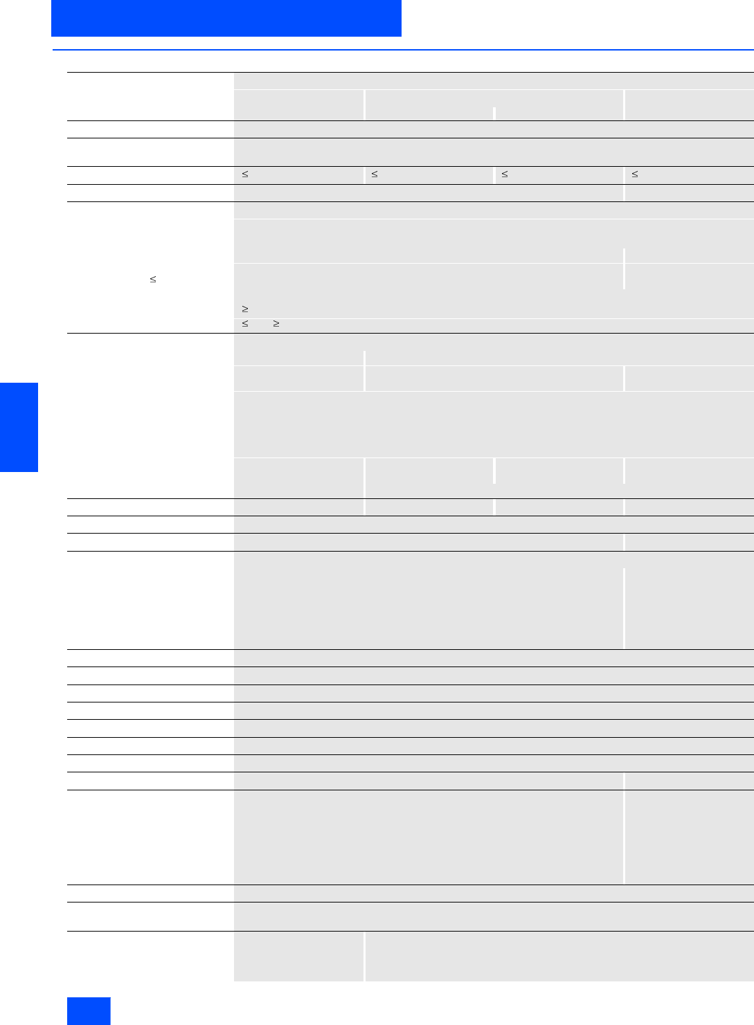
Siemens IK PI · 2004
6/66
AS-Interface Slaves
Digital I/O modules IP67 - application modules
I/O modules for operation in the field
6
■
Technical specifications (continued)
2 inputs/2 outputs
Relay PNP transistor NPN transistor
3RG9 001–0AC00 3RG9 001–0CC00 3RG9 001–0AM00 3RK1 400–1BQ01–0AA3
Slave type Standard slaves
Operational voltage in accordance
with AS-Interface specification in V 26.5 to 31.6
Total current input in mA 140 270 270 290
Input connection PNP NPN
Inputs
• Sensor supply via AS-Interface Short-circuit and overload proof
•Sensors 2- and 3-wire
• Voltage range in V 20 to 30 20 to 27
• Current carrying capacity
for all inputs (Tu 40 °C) in mA 100 200
• Connection of sensors 2- and 3-wire system
• Switching level High in V 10
• Input current Low/High in mA 1.5 / 5
Outputs
• Type of output Relay Electronics
• Current carrying capacity per
output in A DC 12 / DC 13 typ. 1 (DC 12)
0.5 (DC 13 24 V) 2 1
• Maximum summation current
per module in A 2
• Short-circuit protection Built-in
• Inductive interference protection
(free-wheeling diode) Built-in
• External 24 V DC supply voltage Via M 12 plug 24 V DC via black flat
cable Via M 12 plug 24 V DC via black flat
cable
• Watchdog Not available Built-in
Connection of AS-Interface EMI EEMI EMI EEMI
I/O configuration 3
ID code 0 1
Assignment of data bits
• Socket 1 Input (D0) PIN4 = IN1 (D0)
PIN2 = IN2 (D1)
• Socket 2 Input (D1) PIN4 = IN2(D1)
• Socket 3 Output (D2) PIN4 = OUT1 (D2)
PIN2 = OUT2 (D3)
• Socket 4 Output (D3) PIN4 = OUT2 (D3)
AS-Interface certificate Yes
Approvals UL, CSA, ship building
Degree of protection IP67
Ambient temperature in °C -25 to +85
Storage temperature in °C -40 to +85
Number of I/O sockets 4
I/O display Yellow LED
AS-Interface display Green LED Red/yellow/green LED
AS-Interface/diagnostics display Without LED "AS-i" LED:
green = OK
red =
no data communication
flashing red/yellow =
null address
flashing red =
overload sensor
Connection Via contact pin on the FK or Pg coupling module
Note 1 To supply the output circuit, an external supplementary supply (AUX POWER) of 20 to 30 V DC is necessary.
The supplementary supply must comply with VDE 0106 (PELV), Safety Class III.
Note 2 In the event of a commu-
nications failure, the relay
outputs remain in the
current switching state.
–
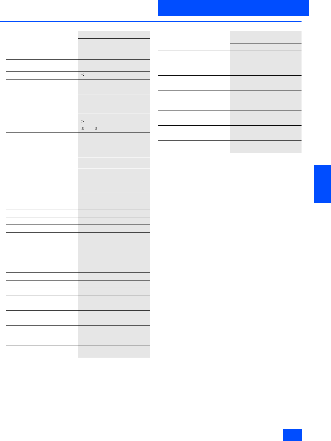
Siemens IK PI · 2004 6/67
AS-Interface Slaves
I/O modules for operation in the field
Digital I/O modules IP67 - application modules
6
■
Technical specifications (continued)
2 x (1 input/1 output)
PNP transistor
3RG9 001–0AJ00
Slave type Standard slaves
Operational voltage in accordance
with AS-Interface specification in V 26.5 to 31.6
Total current input in mA 270
Input connection PNP
Inputs
• Sensor supply via AS-Interface Short-circuit and overload proof
• Voltage range in V 20 to 30
• Load rating for all inputs in mA 200
• Connection of sensors 2-wire system
• Switching level High in V 10
• Input current Low/High in mA 1.5 / 5
Outputs
• Type of output Electronics
• Current carrying capacity per
output in A DC 12 / DC 13 typ. 0.2
• Maximum summation current
per module in A 0.2
• External supply voltage Not required
• Short-circuit protection Built-in
• Inductive interference protection
(free-wheeling diode) Built-in
• External 24 V DC supply voltage The outputs are supplied via the
yellow AS-Interface cable
• Watchdog Built-in
Connection of AS-Interface EMI
I/O configuration 3
ID code F
Assignment of data bits
• Socket 1 Input D0 and output D2
• Socket 2 --
• Socket 3 Input D1 and output D3
• Socket 4 --
AS-Interface certificate Yes
Approvals UL, CSA, ship building
Degree of protection IP67
Ambient temperature in °C -25 to +85
Storage temperature in °C -40 to +85
Number of I/O sockets 2
I/O display Yellow LED
AS-Interface voltage display Green LED
Diagnostics Without LED
Connection Via contact pin on the FK or Pg
coupling module
Note The black AS-Interface cable is
not required
4-fold distributor passive
without LED
3RG9 001-0AD00
Function The passive 4V application mod-
ule is used for connecting the
intelligent I/O to the AS-Interface
Operating voltage in V 26.5 to 31.6 DC (AS-Interface)
Voltage range in V 20 to 30 DC
Current load for all total in A 2
Socket assignment 1 = AS-i ”+“3 = AS-i ”–“
Connection 4 x M12 socket for connecting AS-
Interface (Sensors/actuators)
Degree of protection IP67
Ambient temperature in °C –25 to +85
Non-operating temperature in °C –40 to +85
Number of M12 sockets 4
Connection Via contact pin on the FK or Pg
coupling module
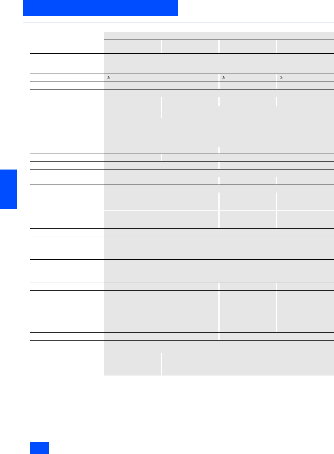
Siemens IK PI · 2004
6/68
AS-Interface Slaves
Digital I/O modules IP67 - application modules
I/O modules for operation in the field
6
■
Technical specifications (continued)
4 outputs
Relay PNP transistor NPN transistor PNP transistor
3RG9 001–0AB00 39 001–0AL00 3RK1 100–1CQ01–0AA3 3RG9 001–0CB00
Slave type Standard slaves
Operational voltage in accordance
with AS-Interface specification in V 26.5 to 31.6
Total current input in mA 60 50 60
Output connection PNP NPN PNP
Outputs
• Type of output Relay Electronics
• Current carrying capacity per
output in A DC 12 / DC 13 typ. 1 (DC 12) 0.5 (DC 13 24
V) 1
• Maximum summation current
per module in A 2
• Short-circuit protection Built-in
• Inductive interference protection
(free-wheeling diode) Built-in
• External 24 V DC supply voltage Via M12 connector on the end face of the module Via FK-E or PG-E coupling module
Watchdog Not available Built-in
Connection of AS-Interface EMI EEMI
I/O configuration 8
ID code 0 1 0
Assignment of data bits
• Socket 1 Output (D0) PIN4 = OUT1 (D0)
PIN2 = OUT2 (D1) Output (D0)
• Socket 2 Output (D1) PIN4 = OUT2(D1) Output (D1)
• Socket 3 Output (D2) PIN4 = OUT3(D2)
PIN2 = OUT4(D3) Output (D2)
• Socket 4 Output (D3) PIN4 = OUT4(D3) Output (D3)
AS-Interface certificate Yes
Approvals UL, CSA, ship building
Degree of protection IP67
Ambient temperature in °C -25 to +85
Storage temperature in °C –40 to +85
Number of I/O sockets 4
Display of outputs Yellow LED
AS-Interface display Green LED Red/yellow/green LED Green LED
Diagnostics Without LED "AS-i" LED:
green = OK
red =
no data communication
flashing red/yellow =
null address
flashing red =
overload sensor
Without LED
Connection Via contact pin on the FK or Pg coupling module Via contact pin on the FK-E or Pg-E coupling module
Note 1 To supply the output circuit, an external supplementary supply (AUX POWER) of 20 to 30 V DC is necessary.
The supplementary supply must comply with VDE 0106 (PELV), Safety Class III.
Note 2 In the event of a commu-
nications failure, the relay
outputs remain in the
current switching state.
–

Siemens IK PI · 2004 6/69
AS-Interface Slaves
I/O modules for operation in the field
Digital I/O modules IP67 - application modules
6
■
Technical specifications (continued)
FK coupling module FK-E coupling module
for 2 x AS-Interface cable (yellow) for 1 x AS-Interface cable (yellow) and
1 x AS-Interface cable (black)
Standard version Version with high-grade
steel components and
Viton seals
Standard version Version with high-grade
steel components and
Viton seals
3RG9 010–0AA00 3RK1 901–1HA00 3RG9 030–0AA00 3RK1 901–1JA00
Operating voltage in accordance
with AS-Interface specification in V 26.5 to 31.6
Loading capability in A 2
Interface EMI EEMI
Ambient temperature in °C -40 to +85
Degree of protection IP67 (with cover/application module)
Connection technique Insulation piercing technique for AS-Interface flat cable
Mounting possibilities For wall and standard rail mounting
Scope of delivery 1 coupling module
4 shaped seal
3 terminating seal
1 coupling module
4 shaped seal (Viton)
3 terminating seal
(Viton)
1 coupling module
4 shaped seal
3 terminating seal
1 coupling module
4 shaped seal (Viton)
3 terminating seal
(Viton)
Special features -- Integrated high-grade
steel threaded bushings -- High-grade steel
threaded bushings
Note Cable baskets are connected electrically in parallel
and are suitable for single T and double T junctions --
PG coupling module PG-E coupling module
3RG9 220-0AA00 3RG9 240-0AA00
Operational voltage in accordance
with AS-Interface specification in V 26,5 to 31,6
Loading capability in A 4
Interface EMI EEMI
Ambient temperature in °C -25 to +85
Degree of protection IP67 (with cover/application module)
Connection technique Via screw terminals to AS-Interface cable
with top section of module Via screw terminals to AS-Interface cable and UAux via
male contact connection to top section of module
Mounting possibilities For wall and standard rail mounting
Supply includes 1 PG coupling module
4 nuts
2 cable gland PG11
3 locking bolts
External cable diameter in mm 6 to 10
Conductor cross-section in mm21 to 2.5
Screwed cable gland Pg11
Note When using AS-Interface flat cables, shaped PG gaskets are required(3RX9 805-0AA00)
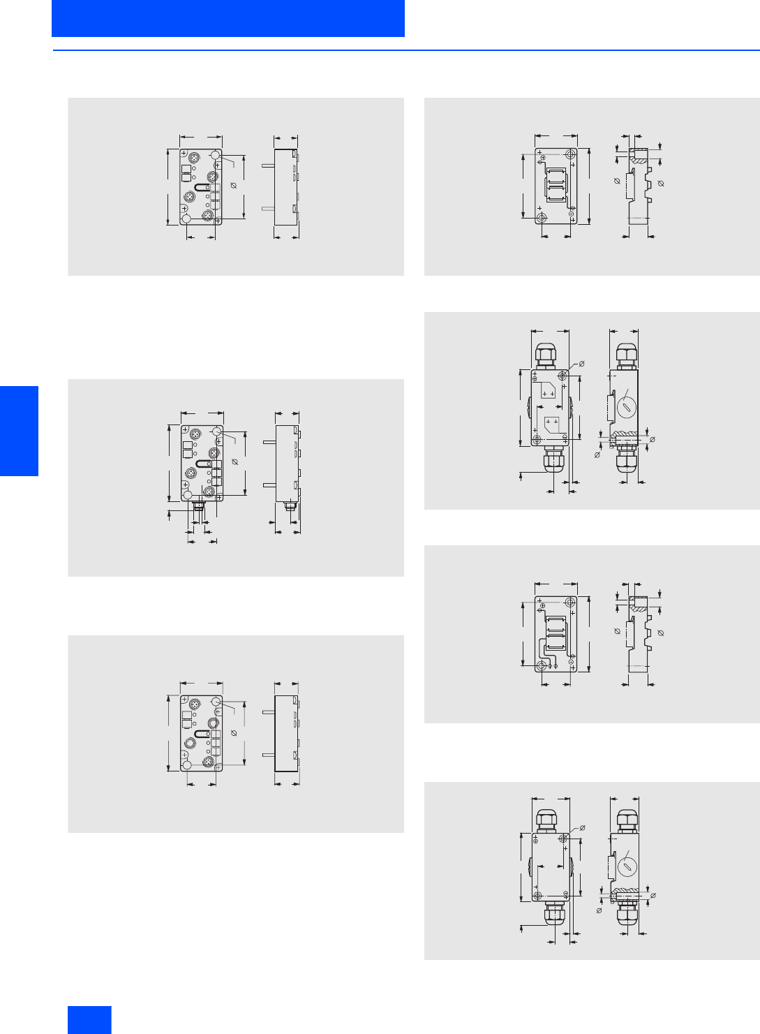
Siemens IK PI · 2004
6/70
AS-Interface Slaves
Digital I/O modules IP67 - application modules
I/O modules for operation in the field
6
■
Dimensional drawings
Application modules
3RG9 001-0AA00
3RG9 001-0AD00
3RG9 001-0AG00
3RG9 001-0CB00
3RG9 001-0CC00
3RK1 200-0CQ01-0AA3
3RK1 400-1BQ01-0AA3
3RK1 100-1CQ01-0AA3
3RG9 001-0AB00
3RG9 001-0AC00
3RG9 001-0AL00
3RG9 001-0AM00
3RG9 001-0AH00
3RG9 001-0AJ00
Coupling modules
FK coupling module
3RG9 010-0AA00
PG coupling module
3RG9 220-0AA00
FK-E coupling module
3RG9 030-0AA00
3RG9 901-1NA00
3RG9 901-1JA00
PG-E coupling module
3RG9 240-0AA00
N S A 0 0 0 3 9
8 0
6 6
3 1
9 , 6
4 5 2 5
- 1
- 2 -
3 -
4 -
2 7
N S A 0 0 0 4 0
8 0
6 6
3 1
9 , 6
4 5 2 5
1 0
3 , 8 5
M 1 2
- 1
- 2 -
3 -
4 -
1 62 7
N S A 0 0 0 4 1
8 0
6 6
3 1
9 , 6
4 5 2 5
2 7
N S A 0 0 0 4 3
8 0
6 6
3 1
5 , 3
4 5 6
9 , 6
2 0
N S A 0 0 0 4 4
8 0
6 6
3 1
4 5
4
17,25
2 2 - 2 8
5 , 3
3 3
13,25
P g 1 1
9 , 6
5 , 3
N S A 0 0 0 4 5
8 0
6 6
3 1
5 , 3
4 5 6
9 , 6
2 0
N S A 0 0 0 4 6
8 0
6 6
3 1
4 5
4
17,25
2 2 - 2 8
5 , 3
3 3
1 3 , 2 5
P g 1 1
9 , 6
5 , 3
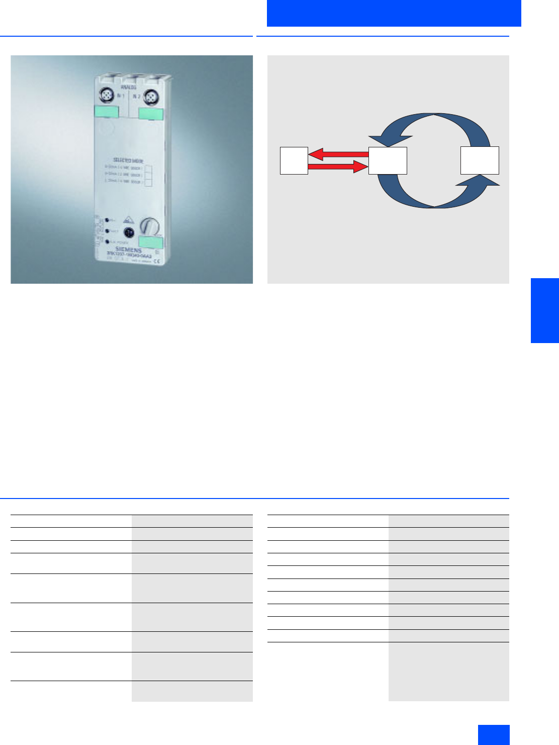
Siemens IK PI · 2004 6/71
AS-Interface Slaves
I/O modules for operation in the field
Analog I/O modules IP67 - K60
6
■
Overview
The two-channel modules in the K60 compact series collect or
supply analog signals locally. These modules are linked to a
higher-level programmable controller via an AS-Interface master
acc. to Specification 2.1.
The analog modules are grouped into five categories:
• Input module for two current sensors
• Input module for two voltage sensors
• Input module for two temperature sensors
• Output module for two current actuators
• Output module for two voltage actuators
The input and output channels are galvanically isolated from the
AS-Interface network. If sensors with a greater power consump-
tion are to be connected, instead of the internal supply, more
power can be supplied via the auxiliary voltage.
The modules, complete with their technical specifications and
detailed operating instructions, are presented in the manual in
considerable detail. This is supplemented with function block
examples.
■
Function
Data transfer in accordance with the 7.3/7.4 analog profile (simplified)
In the case of the 7.3/7.4 analog profile, at least seven AS-Inter-
face cycles are executed until data transfer is complete. For this
purpose, a master with the expanded specification V2.1
must be used.
In the case of input modules, the complete analog value is then
available in the AS-Interface master. Preprocessing takes place
in the master.
The user program fetches the analog value as one value into the
user program on the next system function call. The analog value
is therefore updated extremely quickly.
This procedure takes place in reverse order in the case of output
modules.
■
Technical specifications
NSA0_00352a
A n a l o g
m o d u l e
A S -
I n t e r f a c e
m a s t e r
C P U
O n e u s e r p r o g r a m c y c l e ,
w i t h s y s t e m f u n c t i o n c a l l
S e v e n A S -
I n t e r f a c e c y c l e s
( m a x . 5 m s e a c h )
N o t e : T h e i n t e g r a t e d s t a n d a r d f u n c t i o n b l o c k s S F C 5 8 , S F C 5 9
c a n b e u s e d f o r a c c e s s t o t h e v a l u e s .
Slave type Analog-Slave
Profile 7.3
Numerical format S7
Operational voltage in accordance
with AS-Interface specification in V 26.5 to 31.6
Total current consumption of the
module including the connection
of sensors/actuators in mA
150
Current drawn with two sensors
connected in mA
(without UAux infeed)
Max. 46
Additional supply of sensors
via UAux in V 24 to 30
Current drawn from UAux on
connection of 2 sensors
(not short-circuit-proof) in mA
Max. 500
Current drawn on connection of 2
current / voltage actuators in mA Max. 30 / max. 24
I/O configuration 7
ID code 3
AS-Interface certificate In preparation
Approvals UL/CSA/ship building
Degree of protection IP67
Ambient temperature in °C -20 to +60
Storage temperature in °C -40 to +85
AUX PWR display (UAux)Green LED
AS-i display Green LED
FAULT display Red LED
Connection Mounting plate for K60 compact
module
Siemens IK PI · 2004
6/72
AS-Interface Slaves
Analog I/O modules IP67 - K60
I/O modules for operation in the field
6
■
Selection and Ordering data
Additional information is available in the Internet under:
http://mall.ad.siemens.com
The analog modules to the profile 7.1/7.2 can be ordered at this
address.
Design
Order No.
3RK1 207-1BQ40-0AA3
Analog I/O modules IP67 - K60
Active channels 1 and 2
Analog profile 7.3
The modules are supplied without a mounting plate
Measurement/
output variable Type Measurement
/output range
Current 2 inputs
Deactivated smoothing
function
50 Hz line filter
4 to 20 mA or
20 mA
(selectable)
3RK1 207-1BQ40-0AA3
2 outputs
For 2-wire actuators 4 to 20 mA or
20 mA or
0 to 20 mA
(selectable)
3RK1 107-1BQ40-0AA3
Thermal resistance
Resistance 2 inputs
For 4-wire sensors
Deactivated smoothing
function
50 Hz line filter
Pt 100 or
Ni 100 or
0 to 600 mA
(selectable)
3RK1 207-3BQ40-0AA3
Voltage 2 inputs
Deactivated smoothing
function
50 Hz line filter
10 V
3RK1 207-2BQ40-0AA3
2 outputs
For 2-wire actuators 10 V or
0 to 10 V
(selectable)
3RK1 107-2BQ40-0AA3
Accessories
3RK1 901-0CA00
Manual, German
3RK1 701-2AB40-0AA0
K60 mounting plate
• Wall mounting
3RK1 901-0CA00
• Mounting onto standard rails
3RK1 901-0CB00
3RK1 901-1KA00
M12 sealing cap
3RK1 901-1KA00
3RK1 902-0AR00
Sealing kit
3RK1 902-0AR00
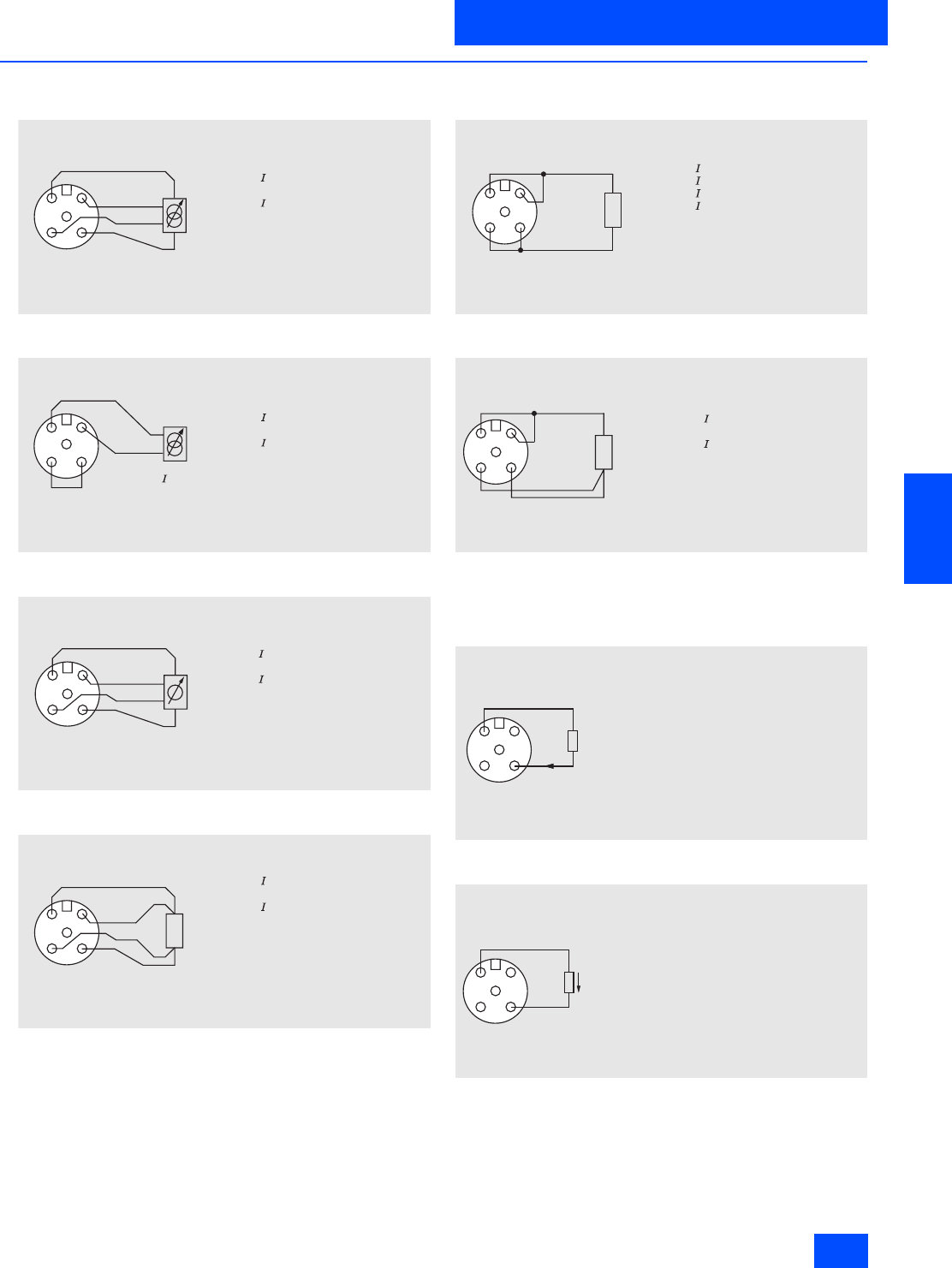
Siemens IK PI · 2004 6/73
AS-Interface Slaves
I/O modules for operation in the field
Analog I/O modules IP67 - K60
6
■
Schematics
Pin assignment input module
3RK1 207-1BQ40-0AA3
Current input 4-wire-sensor
3RK1 207-1BQ40-0AA3
Current input 2-wire-sensor
3RK1 207-2BQ40-0AA3
Voltage input 4-wire-sensor
3RK1 207-3BQ40-0AA3
Thermo-resistor 4-wire-sensor
3RK1 207-3BQ40-0AA3
Thermo-resistor 2-wire-sensor
3RK1 207-3BQ40-0AA3
Thermo-resistor 3-wire-sensor
All Pin assignments without external supply of the sensors.
Pin assignment output module
3RK1 107-1BQ40-0AA3
Current output
3RK1 107-2BQ40-0AA3
Voltage output
All Pin assignments without external supply of the sensors.
N S A 0 _ 0 0 0 1 3 a
1 2
4 3
5
P i n 1 : S u p p l y L + ( D C 2 4 V )
P i n 2 :
P i n 3 : S u p p l y M ( g r o u n d )
P i n 4 :
P i n 5 : C a b l e s h i e l d
A l l p i n a s s i g n m e n t s a r e s h o w n w i t h o u t
e x t e r n a l s e n s o r s u p p l y .
m a x 5 0 m A f o r b o t h c h a n n e l s f r o m
P i n 1 a n d P i n 3 .
n +
n
N S A 0 _ 0 0 0 1 4 b
1 2
4 3
5
P i n 1 : S u p p l y L + ( D C 2 4 V )
P i n 2 :
P i n 3 : S u p p l y M ( g r o u n d )
P i n 4 :
P i n 5 : C a b l e s h i e l d
A l l p i n a s s i g n m e n t s a r e s h o w n w i t h o u t
e x t e r n a l s e n s o r s u p p l y .
m a x 5 0 m A f o r b o t h c h a n n e l s f r o m
P i n 1 a n d P i n 3 .
n
n +
B r i d g e f r o m t o M ( 3 )
c a n b e s e t i n t e n a l l y v i a
p a r a m e t e r i s a t i o n
n
N S A 0 _ 0 0 0 1 7 a
1 2
4 3
5
P i n 1 : S u p p l y L + ( D C 2 4 V )
P i n 2 :
P i n 3 : S u p p l y M ( g r o u n d )
P i n 4 :
P i n 5 : C a b l e s h i e l d
A l l p i n a s s i g n m e n t s a r e s h o w n w i t h o u t
e x t e r n a l s e n s o r s u p p l y .
m a x 5 0 m A f o r b o t h c h a n n e l s f r o m
P i n 1 a n d P i n 3 .
n +
n
N S A 0 _ 0 0 0 1 8 a
1 2
4 3
5P t 1 0 0
P i n 1 :
P i n 2 : I N +
P i n 3 :
P i n 4 : I N
P i n 5 : C a b l e s h i e l d
A l l p i n a s s i g n m e n t s a r e s h o w n w i t h o u t
e x t e r n a l s e n s o r s u p p l y .
m a x 5 0 m A f o r b o t h c h a n n e l s f r o m
P i n 1 a n d P i n 3 .
c o n s t +
c o n s t
N S A 0 _ 0 0 0 1 5 b
1 2
4 3
5P t 1 0 0
P i n 1 :
P i n 2 :
P i n 3 :
P i n 4 :
P i n 5 : C a b l e s h i e l d
A l l p i n a s s i g n m e n t s a r e s h o w n w i t h o u t
e x t e r n a l s e n s o r s u p p l y .
m a x 5 0 m A f o r b o t h c h a n n e l s f r o m
P i n 1 a n d P i n 3 .
n +
n
c o n s t +
c o n s t
N S A 0 _ 0 0 0 1 9 a
1 2
4 3
5 P t 1 0 0
P i n 1 :
P i n 2 : S u p p l y L +
P i n 3 :
P i n 4 : S u p p l y L ( g r o u n d )
P i n 5 : C a b l e s h i e l d
m e a s +
m e a s
N S A 0 _ 0 0 0 1 6
12
43
5
P i n 5 : C a b l e s h i e l d
N S A 0 _ 0 0 0 2 0
1 2
4 3
5
P i n 5 : C a b l e s h i e l d

Siemens IK PI · 2004
6/74
AS-Interface Slaves
Pneumatic I/O modules
I/O modules for operation in the field
6
■
Overview
All pneumatic I/O modules must now be ordered directly from
the manufacturer (Fa. Kuhnke). An order via Siemens is no
longer possible.
Order informationen of Kuhnke GmbH
Module groupe Module type Siemens Order No. Kuhnke order code Ordering adress
Pneumatic compact module K60
4 inputs
2 outputs
monostable
Exhaust air via sintered filter 3RK 1408-0MT00-0CA0 AirBox K-F-GE-MO Kuhnke GmbH
Lütjenburger Str. 101
D-23714 Malente
Tel.
x49-4523-402-386
Fax.
x49-4523-402-481
E-mail:
sales@kuhnke.de
Contact person:
Mr Pöhls
Exhaust air via plug-in
connector 3RK 1408-0MT01-0CA0 AirBox K-S-GE-MO
Exhaust air via sintered filter
valve supply via U aux 3RK 1408-1MT00-0CA0 AirBox K-F-SW-MO
Exhaust air via plug-in
connector
valve supply via U aux
3RK 1408-1MT01-0CA0 AirBox K-S-SW-MO
Pneumatic compact module K60
4 inputs
2 outputs
bistable
Exhaust air via sintered filter 3RK 1408-0CT00-0CA0 AirBox K-F-GE-BI
Exhaust air via plug-in
connector 3RK 1408-0CT01-0CA0 AirBox K-S-GE-BI
Exhaust air via sintered filter
valve supply via U aux 3RK 1408-1CT00-0CA0 AirBox K-F-SW-BI
Exhaust air via plug-in
connector
valve supply via U aux
3RK 1408-1CT01-0CA0 AirBox K-S-SW-BI
Pneumatic application module
2 inputs
2 outputs
monostable
Exhaust air via sintered filter 3RK 1408-0BT00-0CA0 AirBox 1-F-GE-MO
Exhaust air via plug-in
connector 3RK 1408-0BT01-0CA0 AirBox 1-S-GE-MO
Exhaust air via plug-in
connector
with stainless-steel compo-
nents and Viton seals
3RK 1408-0BT03-0CA0 AirBox 1-S-GE-MO-VA
Exhaust air via sintered filter
recessed hand operation 3RK 1408-0BT02-0CA0 AirBox 1-F-GE-MO-GH
Pneumatic application module
2 2 inputs
2 outputs
monostable
Exhaust air via sintered filter
recessed hand operation
valve supply via U aux
3RK 1408-1BT02-0CA0 AirBox 32-F-SW-MO-GH
Exhaust air via sintered filter 3RK 1408-0MT02-0CA0 AirBox 32-F-GE-MO
Exhaust air via plug-in con-
nector 3RK 1408-0MT03-0CA0 AirBox 32-S-GE-MO
Exhaust air via sintered filter
valve supply via U aux 3RK 1408-1BT00-0CA0 AirBox 32-F-SW-MO
Exhaust air via plug-in
connector
valve supply via U aux
3RK 1408-1BT01-0CA0 AirBox 32-S-SW-MO
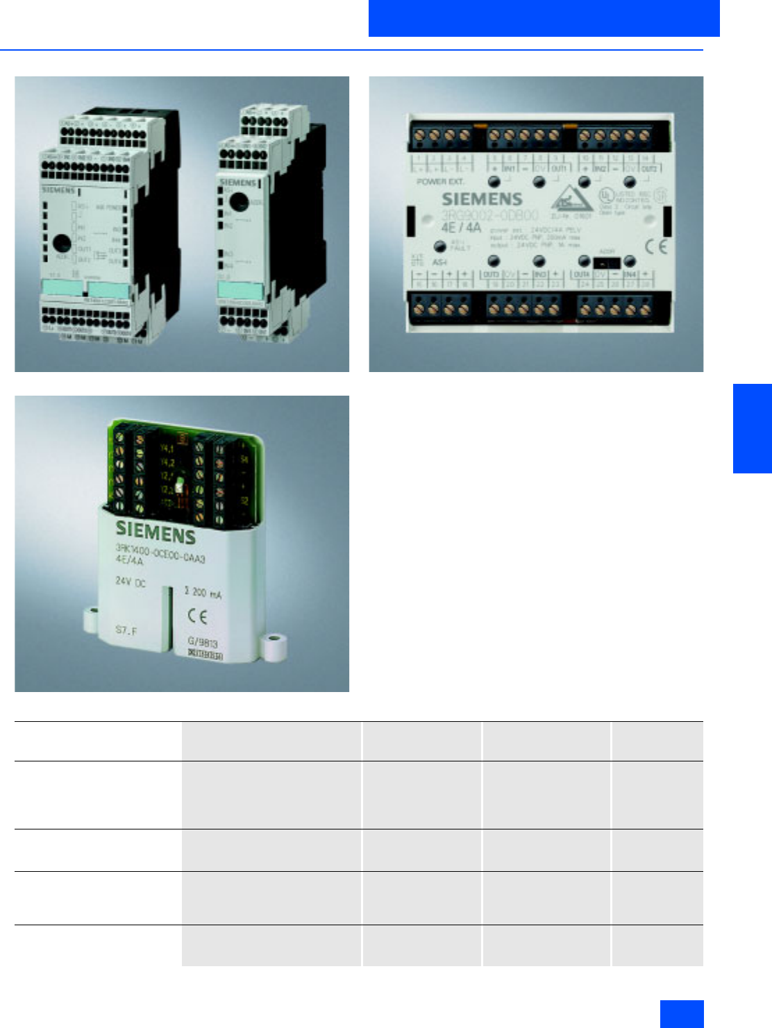
Siemens IK PI · 2004 6/75
AS-Interface Slaves
I/O modules for operation in IP20 control cabinet
Introduction
6
■
Overview
SlimLine S22.5/S45
Flat module
Module F90
For AS-Interface applications in the switchgear cabinet, various
module series are available for different requirements:
• SlimLine S22.5
• SlimLine S45
• Module F90
• Flat module
All modules of these series can be directly snapped onto stan-
dard rails or fixed with screws.
AS-Interface modules to the degree of protection IP20 have ter-
minals for direct connection to the AS-Interface cables and
therefore do not require a base unit.
1) For further information about these modules, see Section Actuator-Sensor-Interface / Modules with special functions / Counter modules
Series Range Mounting on 35 mm
standard rails to
DINEN50022
Wall mounting using
push-in lugs
(Order No.: 3RP1 903)
Other
possibilities
SlimLine S22.5 •4I
•4O
• 2I/2O (electronic/relay outputs)
• Counter 1)
• Earth fault detection module
• • –
SlimLine S45 • 4I/4O (electronic/relay outputs)
• 4I/4O with floating I/O
• 4I/3O (A/B modules)
• • –
Module F90 • 4I/4O (screw terminals)
• 4I/4O (connected via Combicon
connector)
• 16I
• – –
Flat module • 4I/4O (screw terminals)
• (encapsulated and embedded
PCB)
– – Integrated tags
for screw fixing
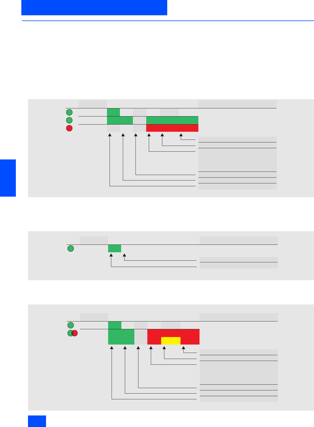
Siemens IK PI · 2004
6/76
AS-Interface Slaves
Introduction
I/O modules for operation in IP20 control cabinet
6
■
Function
Addressing
All modules of the Slimline S22.5, S45 and F90 series as well as
the flat module can be addressed via an integrated addressing
socket also in the mounted state. An addressing unit is therefore
necessary (AS-Interface addressing and diagnostics unit 3RK1
904-2AB01).
LED diagnostics indication
SlimLine Series
AS-Interface modules of the SlimLine Series have, in addition to
status indicators for inputs and outputs, two LEDs for indicating
the status of the module.
1) No LED for 3RK1 400-0BE00-0AA2, 3RK1 402-0BE00-0AA2 and 3RK1 100-0CE00-0AA2.
F90 module (16I)
All modules of this series have, in addition to status indicators for
inputs and outputs, one LED to indicate the status of the AS-In-
terface voltage.
Flat module and F90 module (4I/4O)
The flat module and F90 module with four inputs and four out-
puts have a dual LED for diagnostics functions.
LED
AUX PWR1)
AS-Interface
FAULT
NSA0_00318
States
Off Off
Off
OffOff Off
Status description
On
On On On
On On
On
Flashing
Flashing
Sensor overload with RESET of slaves
Slave has address = 0
No communication:
Master in STOP mode
Slave not entered in the LPS
Slave has wrong IO&D code
Slave in RESET state
Module completely without voltage
UAux failure Normal operation and
UAux applied
LED
AS-Interface
NSA0_00319
AS-Interface voltage not applied
AS-Interface voltage applied
States
Off
Status description
On
LED
AUX PWR
AS-i / FAULT
NSA0_00313
States
Off Off
Off
Status description
Sensor overload with RESET of slaves
Slave has address = 0
No communication:
Master in STOP mode
Slave not entered in the LPS
Slave has wrong IO&D code
Slave in RESET state
Module completely without voltage
UAux failure
Normal operation and UAux applied
On
On On On Flashing Flashing
Flashing
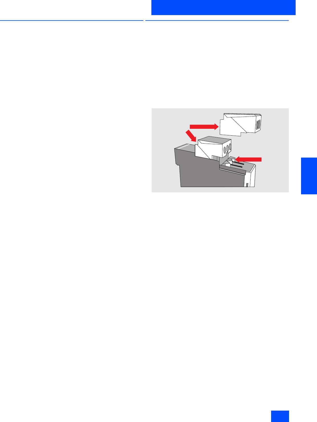
Siemens IK PI · 2004 6/77
AS-Interface Slaves
I/O modules for operation in IP20 control cabinet
SlimLine
6
■
Overview
SlimLine modules of Series S22.5 and S45
The AS-Interface module series for the "SlimLine“ control cabinet
to the degree of protection IP20 creates space in the control
cabinet or in the distributed on-site control box.
The emphasis of this module series is on its slim design. The
modules are 22.5 mm or 45 mm in width.
Via screw-type or Cage Clamp terminals, standard sensors/
actuators and the AS-Interface cable can be connected.
Integrated adapters allow the modules to be mounted on stan-
dard rails. Deinstallation from the standard rail is quick and easy
without the need for tools.
The modules can also be screwed in place by an additional
accessory.
All modules have LEDs on the front which indicate the status of
the module.
An addressing socket built into the front allows addresses to be
assigned in the installed state.
Apart from the digital input and output modules, modules with
special functions are also available in S22.5 format. These in-
clude:
• Counter module
• Earth fault detection module
For further information on these modules, see the Section
AS-Interface / Modules with Special Functions.
■
Design
Removable terminals
The removable terminal is the innovative connection technique
from Siemens for AS-Interface SlimLine modules of the S22.5
and S45 Series. The complete terminal block can be quickly and
easily dismantled and reassembled. It is not necessary to dis-
connect the terminals during this process.
Note
• The devices will be converted from 2004 and will be available
under the same order number.
• Before the terminal block is removed, the device must be dis-
connected from the supply.
Features
•Well-proven terminal system
The complete ease of handling for connecting wires is retained
in the design of the new removable terminals. The familiar con-
ductor cross sections can continue to be used.
•Variable connection techniques
All modules are available with screw-type or Cage Clamp ter-
minals.
•Coding
The terminal blocks cannot be mistakenly interchanged thanks
to coding (EN50178).
•Secured against detachment and vibration
The terminal blocks are latched into the housing. The terminal
blocks can be removed using a screwdriver VDE0100T410
(IEC-4-41). Inadvertent removal is therefore not possible.
•Safety against finger touch
Even in the removed state, the contacts of the modules are safe
against finger touch according to DIN 61140(IEC 60529).
•Labeling
All terminal connections are labelled on the terminal block
which makes preassembly possible.
NSA0_00363
Removeable
terminal blocks
Contact
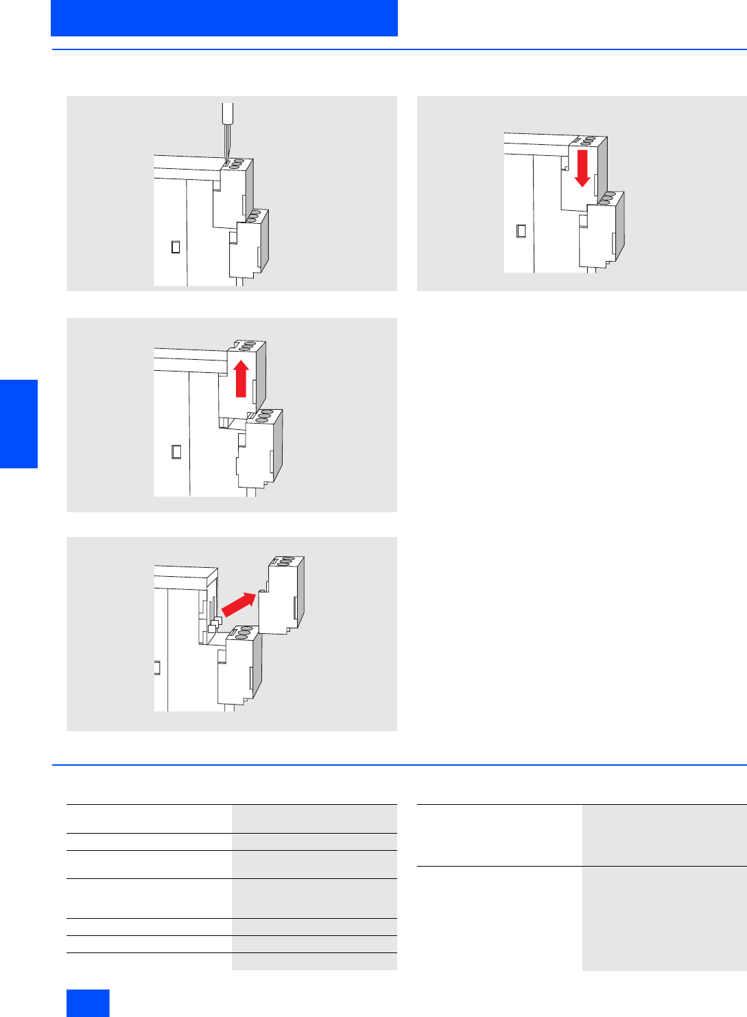
Siemens IK PI · 2004
6/78
AS-Interface Slaves
SlimLine
I/O modules for operation in IP20 control cabinet
6
■
Design (continued)
Releasing removable terminals
Step 1: Release latch using a screwdriver
Step 2: Pull terminal forwards
Step 3: Lift off terminal
Locking removable terminals
Push terminal backwards until latch snaps into place
Customer benefits
• Quick replacement of the basic unit minimizes service costs
and reduces downtimes
• Mistakes are avoided during replacement thanks to coding of
the terminals
• Preassembly is possible without the device
• Safety to finger touch during replacement
• The ease of connection with screw-type and Cage Clamp ter-
minals is fully retained
■
Technical specifications
Technical specifications common to all SlimLine modules
NSA0_00364
NSA0_00365
NSA0_00366a
NSA0_00367a
CLICK
Operational voltage in accordance
with AS-Interface specification in V 26.5 to 31.6
Input connection PNP
AS-Interface certificate Available (or under application in
the case of new products)
Approvals UL, CSA, ship building (or under
application in the case of new
products)
Degree of protection IP20
Ambient temperature in °C -25 to +70
Storage temperature in °C -40 to +85
Status indications
• I/O display Yellow LED
• AS-i display Green LED
• FAULT display Red LED
Note To supply the output circuit,
an external supplementary
supply (AUX POWER)
of 20 to 30 V DC is necessary.
The supplementary supply must
comply with VDE 0106 (PELV),
Safety Class III.
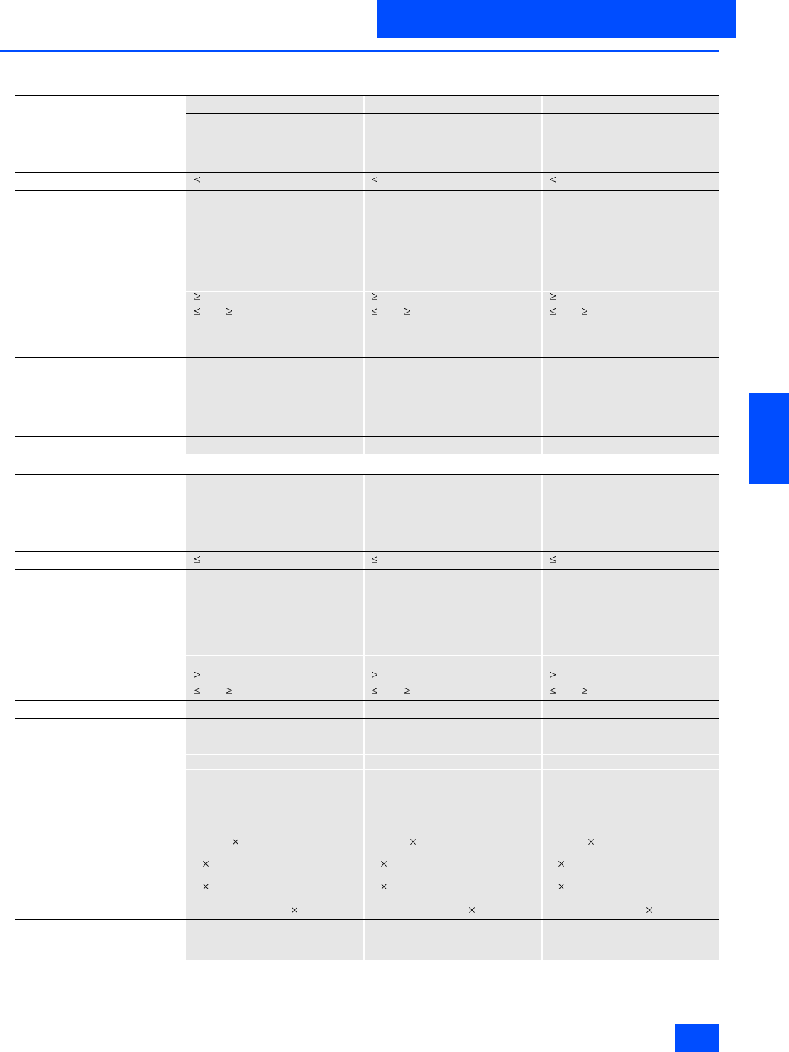
Siemens IK PI · 2004 6/79
AS-Interface Slaves
I/O modules for operation in IP20 control cabinet
SlimLine
6
■
Technical specifications (continued)
SlimLine S22.5
4 inputs 4 inputs 4 inputs new
Screw-type connection Screw-type connection Screw-type connection
Standard slave Standard slave A/B slave
2-wire 2- and 3-wire 2- and 3-wire
3RK1 200-0CE00-0AA2 3RK1 200-0CE02-0AA2 3RK2 200-0CE02-0AA2
Total current input in mA 50 270 270
Inputs
• Sensor supply via AS-Interface Short circuit and overload
withstand capability Short circuit and overload
withstand capability Short circuit and overload
withstand capability
• Voltage range in V 20 to 30 20 to 30 20 to 30
• Current carrying capacity
for sensor supply in mA -- 200 200
• Connection of sensors 2-wire system 2- and 3-wire system 2- and 3-wire system
• Switching level High in V 10 10 10
• Input current Low/High in mA 1.5 / 5 1.5 / 5 1.5 / 5
I/O configuration 0 0 0
ID/ID2 code 0/F 0/F A/0
Assignment of data bits
•Data bit D0 IN1 IN1 IN1
•Data bit D1 IN2 IN2 IN2
•Data bit D2 IN3 IN3 IN3
•Data bit D3 IN4 IN4 IN4
Connection Via screw terminal Via screw terminal Via screw terminal
4 inputs 4 inputs 4 inputs new
Spring-loaded connection Spring-loaded connection Spring-loaded connection
Standard slave Standard slave A/B slave
2-wire 2- and 3-wire 2- and 3-wire
3RK1 200-0CG00-0AA2 3RK1 200-0CG02-0AA2 3RK2 200-0CG02-0AA2
Total current input in mA 50 270 270
Inputs
• Sensor supply via AS-Interface Short-circuit and overload
withstand capability Short-circuit and overload
withstand capability Short-circuit and overload
withstand capability
• Voltage range in V 20 to 30 20 to 30 20 to 30
• Current carrying capacity
for sensor supply in mA -- 200 200
• Connection of sensors 2-wire system 2- and 3-wire system 2- and 3-wire system
• Switching level High in V 10 10 10
• Input current Low/High in mA 1.5 / 5 1.5 / 5 1.5 / 5
I/O configuration 0 0 0
ID/ID2 code 0/F 0/F A/0
Assignment of data bits
•Data bit D0 IN1 IN1 IN1
•Data bit D1 IN2 IN2 IN2
•Data bit D2 IN3 IN3 IN3
•Data bit D3 IN4 IN4 IN4
Connection Spring-loaded terminal connection Spring-loaded terminal connection Spring-loaded terminal connection
Conductor cross-sections in mm2Solid: 2 (0.25–1.5)
Finely stranded with end sleeve:
2 (0.25–1)
Finely stranded without end sleeve:
2 (0.25–1.5)
AWG conductor connections solid
or stranded: AWG 2 (24–16)
Solid: 2 (0.25–1.5)
Finely stranded with end sleeve:
2 (0.25–1)
Finely stranded without end sleeve:
2 (0.25–1.5)
AWG conductor connections solid
or stranded: AWG 2 (24–16)
Solid: 2 (0.25–1.5)
Finely stranded with end sleeve:
2 (0.25–1)
Finely stranded without end sleeve:
2 (0.25–1.5)
AWG conductor connections solid
or stranded: AWG 2 (24–16)
Note Disassembly tool for spring-
loaded terminal connection:
See "Accessories"
Disassembly tool for spring-
loaded terminal connection:
See "Accessories"
Disassembly tool for spring-
loaded terminal connection:
See "Accessories"
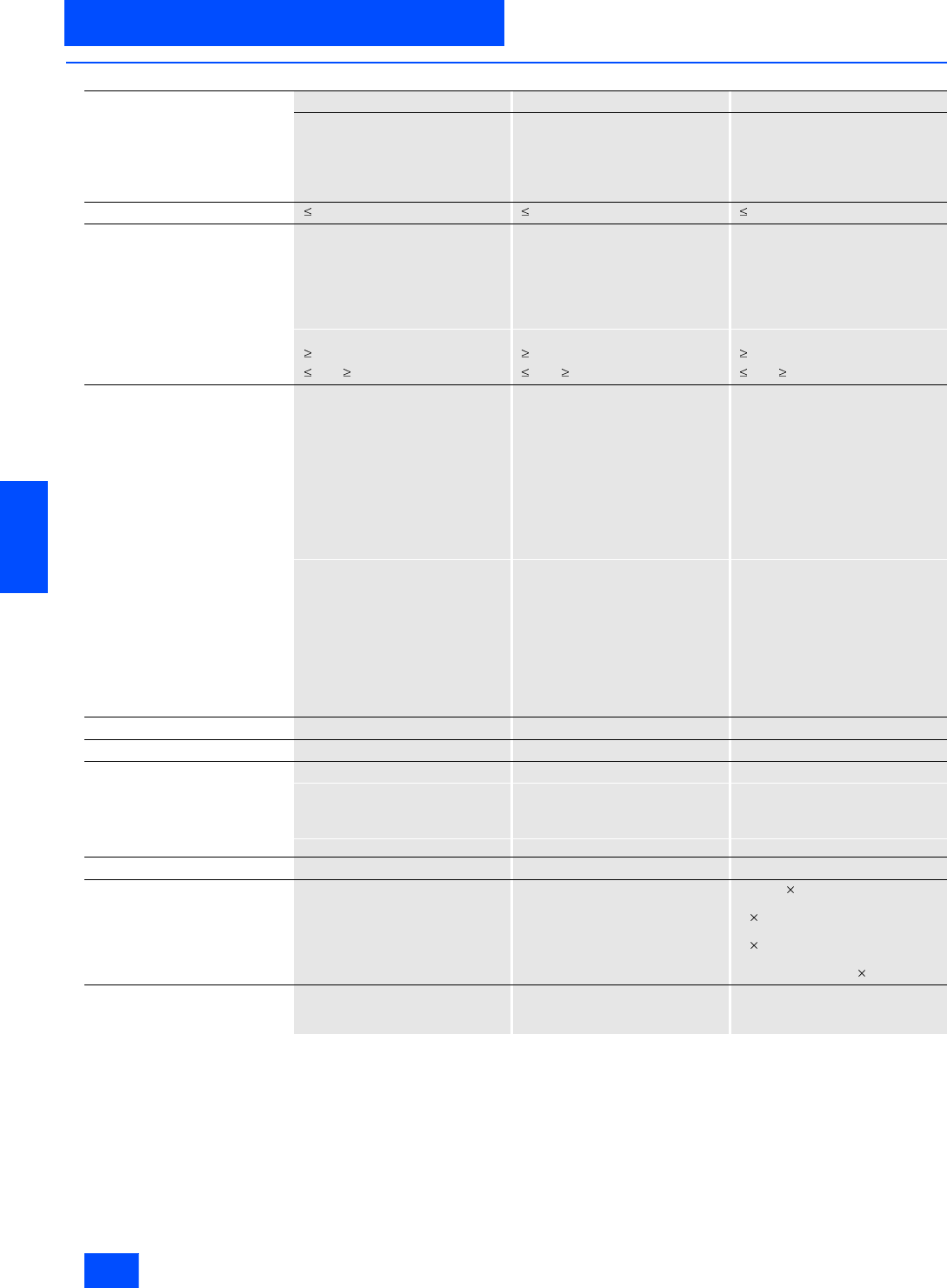
Siemens IK PI · 2004
6/80
AS-Interface Slaves
SlimLine
I/O modules for operation in IP20 control cabinet
6
■
Technical specifications (continued)
2 inputs/2 outputs 2 inputs/2 outputs 2 inputs/2 outputs
Screw-type connection Screw-type connection Spring-loaded connection
Standard slave Standard slave Standard slave
2-wire 2-wire 2-wire
PNP transistor (2 A) Relay PNP transistor (2 A)
3RK1 400-0BE00-0AA2 3RK1 402-0BE00-0AA2 3RK1 400-0BG00-0AA2
Total current input in mA 50 50 50
Inputs
• Sensor supply via AS-Interface Short-circuit and overload with-
stand capability Short-circuit and overload with-
stand capability Short-circuit and overload with-
stand capability
• Voltage range in V 20 to 30 20 to 30 20 to 30
• Current carrying capacity
for sensor supply in mA -- -- --
• Connection of sensors 2-wire system 2-wire system 2-wire system
• Switching level High in V 10 10 10
• Input current Low/High in mA 1.5 / 5 1.5 / 5 1.5 / 5
Outputs
• Type of output PNP transistor Relay PNP transistor
• Current carrying capacity
per output in A DC 12 / DC 13 typ. 2-- 2
• Maximum summation current
per module in A 4-- 4
• Short-circuit protection Built-in External back-up fuse Built-in
• Inductive interference protection
(free-wheeling diode) Built-in Not applicable Built-in
• Polarity reversal protection Not built-in Not applicable Not built-in
• External 24 V DC supply voltage Via terminals:
Terminal 7 = "+“
Terminal 10 = "-“
Not applicable Via terminals:
Ter mi nal 7 ="+“
Ter mi nal 10 = "-“
•I
th -- 6--
•AC-15 -- 3--
•DC 13 24 V -- 1--
• DC 13 110 V -- 0.2 --
• DC 13 230 V -- 0.1 --
• Watchdog Built-in Built-in Built-in
I/O configuration 3 3 3
ID/ID2 code 0/F 0/F 0/F
Assignment of data bits
•Data bit D0 IN1 IN1 IN1
•Data bit D1 IN2 IN2 IN2
•Data bit D2 OUT1 OUT1 OUT1
•Data bit D3 OUT2 OUT2 OUT2
Connection Screw terminals Screw terminals Spring-loaded terminal connection
Conductor cross-sections in mm2-- -- Solid: 2 (0.25–1.5)
Finely stranded with end sleeve:
2 (0.25–1)
Finely stranded without end sleeve:
2 (0.25–1.5)
AWG conductor connections solid
or stranded: AWG 2 (24–16)
Note -- -- Disassembly tool for spring-
loaded terminal connection:
See accessories

Siemens IK PI · 2004 6/81
AS-Interface Slaves
I/O modules for operation in IP20 control cabinet
SlimLine
6
■
Technical specifications (continued)
2 inputs/2 outputs 4 outputs 4 outputs
Spring-loaded connection Screw-type connection Spring-loaded connection
Standard slave Standard slave Standard slave
2-wire -- --
Relay PNP transistor (1 A) PNP transistor (1 A)
3RK1 402-0BG00-0AA2 3RK1 100–1CE00–0AA2 3RK1 100–1CG00–0AA2
Total current input in mA 50 40 40
Inputs
• Sensor supply via AS-Interface Short-circuit and overload with-
stand capability -- --
• Voltage range in V 20 to 30 -- --
• Current carrying capacity
for sensor supply in mA -- -- --
• Connection of sensors 2-wire system -- --
• Switching level High in V 10 -- --
• Input current Low/High in mA 1.5 / 5 -- --
Outputs
• Type of output Relay
changeover, floating Electronics (PNP) Electronics (PNP)
• Current carrying capacity
per output in A DC 12 / DC 13 typ. -- 1 1
• Maximum summation current
per module in A -- 2 2
• Short-circuit protection External back-up fuse necessary Built-in Built-in
• Inductive interference protection
(free-wheeling diode) Not applicable Built-in Built-in
• Polarity reversal protection Not applicable Built-in Built-in
• External 24 V DC supply voltage Not applicable Via screw terminals
Terminal 7 ="+"
Terminal 10 = M
Via screw terminals
Ter mi nal 7 ="+"
Ter mi nal 10 = M
•Ith 6-- --
•AC-15 3-- --
•DC 13 24 V 1-- --
• DC 13 110 V 0.2 -- --
• DC 13 230 V 0.1 -- --
• Watchdog Built-in Built-in Built-in
I/O configuration 3 8 8
ID/ID2 code 0/F 0/F 0/F
Assignment of data bits
•Data bit D0 IN1 OUT1 OUT1
•Data bit D1 IN2 OUT2 OUT2
•Data bit D2 OUT1 OUT3 OUT3
•Data bit D3 OUT2 OUT4 OUT4
Connection Spring-loaded terminal connection Screw terminals Spring-loaded terminal connection
Conductor cross-sections in mm2Solid: 2 (0.25–1.5)
Finely stranded with end sleeve:
2 (0.25–1)
Finely stranded without end sleeve:
2 (0.25–1.5)
AWG conductor connections solid
or stranded: AWG 2 (24–16)
-- Solid: 2 (0.25–1.5)
Finely stranded with end sleeve:
2 (0.25–1)
Finely stranded without end sleeve:
2 (0.25–1.5)
AWG conductor connections solid
or stranded: AWG 2 (24–16)
Note Disassembly tool for spring-
loaded terminal connection:
See "Accessories"
-- Disassembly tool for spring-
loaded terminal connection:
See "Accessories"
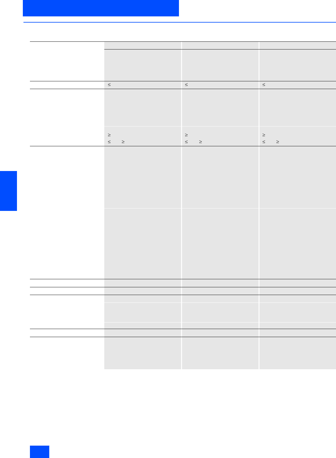
Siemens IK PI · 2004
6/82
AS-Interface Slaves
SlimLine
I/O modules for operation in IP20 control cabinet
6
■
Technical specifications (continued)
SlimLine S45
4 inputs/4 outputs 4 inputs/4 outputs 4 inputs/4 outputs
Screw-type connection Screw-type connection Screw-type connection
Standard slave Standard slave Standard slave
2- and 3-wire 2- and 3-wire 2- and 3-wire (floating)
PNP transistor (1 A) PNP transistor (2 A) PNP transistor (1 A) floating
3RK1 400-1CE00-0AA2 3RK1 400-1CE01-0AA2 3RK1 402-3CE01-0AA2
Total current input in mA 270 270 40
Inputs
• Sensor supply via AS-Interface Short-circuit and overload
withstand capability Short-circuit and overload
withstand capability Short-circuit and overload
withstand capability
• Voltage range in V 20 to 30 20 to 30 20 to 30
• Current carrying capacity
for sensor supply in mA 200 200 200
• Connection of sensors 2- and 3-wire system 2- and 3-wire system 2- and 3-wire system
• Switching level High in V 10 10 10
• Input current Low/High in mA 1.5 / 5 1.5 / 5 1.5 / 5
Outputs
• Type of output Electronics Electronics Electronics
• Current carrying capacity
per output in A DC 12 / DC 13 typ. 1 2 1
• Maximum summation current
per module in A 4 4 4
• Short-circuit protection Built-in Built-in Built-in
• Inductive interference protection
(free-wheeling diode) Built-in Built-in Built-in
• Polarity reversal protection Built-in Built-in Built-in
• External 24 V DC supply voltage Terminal 13 = L24+
Terminal 19 = M24 Terminal 13 = L24+
Terminal 19 = M24 Sensor supply:
Ter mi nal 13 = U_s+
Ter mi nal 19 = U_s–
Actuator supply:
Terminal 14 = L+
Terminals 20 to 24 = M
•Ith -- -- --
•AC-15 -- -- --
•DC 13 24 V -- -- --
• DC 13 110 V -- -- --
• DC 13 230 V -- -- --
• Watchdog Built-in Built-in Built-in
I/O configuration 7 7 7
ID/ID2 code 0/F 0/F 0/F
Assignment of data bits
•Data bit D0 IN1/OUT1 IN1/OUT1 IN1/OUT1
•Data bit D1 IN2/OUT2 IN2/OUT2 IN2/OUT2
•Data bit D2 IN3/OUT3 IN3/OUT3 IN3/OUT3
•Data bit D3 IN4/OUT4 IN4/OUT4 IN4/OUT4
Connection Via screw terminal Via screw terminal Via screw terminal
Note -- -- The module has four floating inputs
and four floating switching outputs.
For the input and output circuits, an
external additional supply of 20 to
30 V according to VDE 0106 (PELV)
Safety Class III is required.
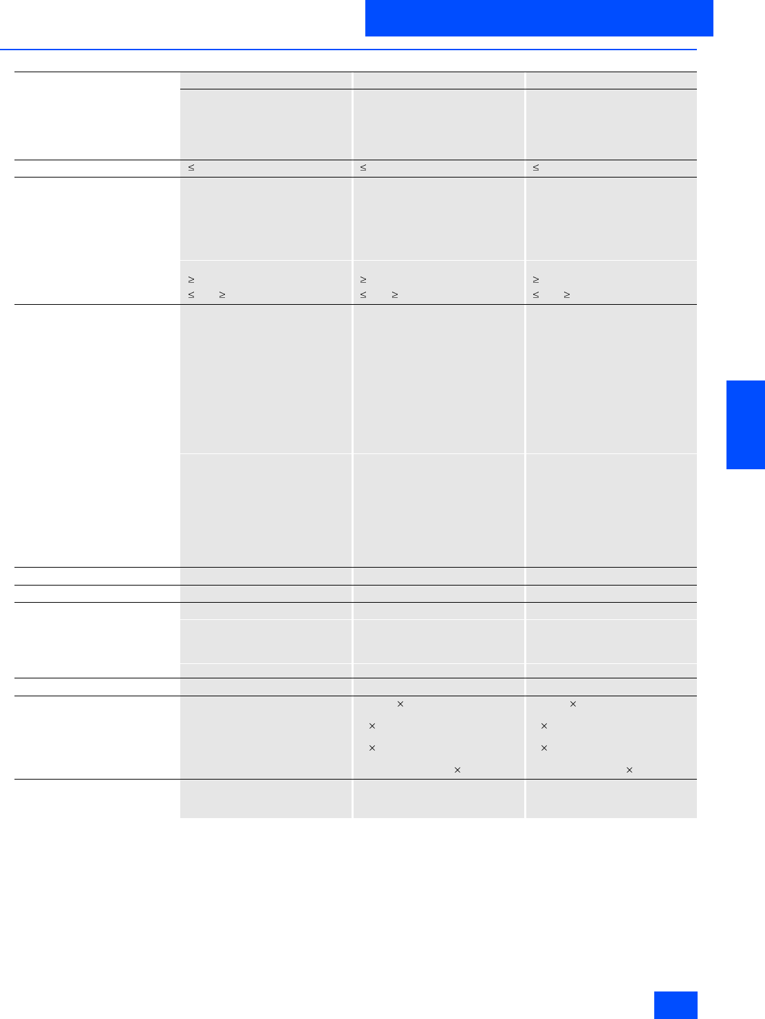
Siemens IK PI · 2004 6/83
AS-Interface Slaves
I/O modules for operation in IP20 control cabinet
SlimLine
6
■
Technical specifications (continued)
4 inputs/4 outputs 4 inputs/4 outputs 4 inputs/4 outputs
Screw-type connection Spring-loaded connection Spring-loaded connection
Standard slave Standard slave Standard slave
2- and 3-wire 2- and 3-wire 2- and 3-wire
Relay PNP transistor (1 A) PNP transistor (2 A)
3RK1 402-3CE00-0AA2 3RK1 400-1CG00-0AA2 3RK1 400-1CG01-0AA2
Total current input in mA 270 270 270
Inputs
• Sensor supply via AS-Interface Short-circuit and overload
withstand capability Short-circuit and overload
withstand capability Short-circuit and overload
withstand capability
• Voltage range in V 20 to 30 20 to 30 20 to 30
• Current carrying capacity
for sensor supply in mA 200 200 200
• Connection of sensors 2- and 3-wire system 2- and 3-wire system 2- and 3-wire system
• Switching level High in V 10 10 10
• Input current Low/High in mA 1.5 / 5 1.5 / 5 1.5 / 5
Outputs
• Type of output Relay Electronics Electronics
• Current carrying capacity
per output in A DC 12 / DC 13 typ. -- 1 2
• Maximum summation current
per module in A -- 4 4
• Short-circuit protection External back-up fuse 6 A gL/gG Built-in No (internal
fusible link)
• Inductive interference protection
(free-wheeling diode) Not applicable -- --
• Polarity reversal protection -- Built-in Built-in
• External 24 V DC supply voltage Not applicable Terminal 13 = L24+
Terminal 19 = M24 Terminal 13 = L24+
Ter mi nal 19 = M24
•Ith 5-- --
•AC-15 3-- --
•DC 13 24 V 1-- --
• DC 13 110 V 0.2 -- --
• DC 13 230 V 0.1 -- --
• Watchdog Built-in Built-in Built-in
I/O configuration 7 7 7
ID/ID2 code 0/F 0/F 0/F
Assignment of data bits
•Data bit D0 IN1/OUT1 IN1/OUT1 IN1/OUT1
•Data bit D1 IN2/OUT2 IN2/OUT2 IN2/OUT2
•Data bit D2 IN3/OUT3 IN3/OUT3 IN3/OUT3
•Data bit D3 IN4/OUT4 IN4/OUT4 IN4/OUT4
Connection Via screw terminal Spring-loaded terminal connection Spring-loaded terminal connection
Conductor cross-sections in mm2-- Solid: 2 (0.25–1.5)
Finely stranded with end sleeve:
2 (0.25–1)
Finely stranded without end sleeve:
2 (0.25–1.5)
AWG conductor connections solid
or stranded: AWG 2 (24–16)
Solid: 2 (0.25–1.5)
Finely stranded with end sleeve:
2 (0.25–1)
Finely stranded without end sleeve:
2 (0.25–1.5)
AWG conductor connections solid
or stranded: AWG 2 (24–16)
Note -- Disassembly tool for spring-
loaded terminal connection:
See "Accessories"
Disassembly tool for spring-
loaded terminal connection:
See "Accessories"

Siemens IK PI · 2004
6/84
AS-Interface Slaves
SlimLine
I/O modules for operation in IP20 control cabinet
6
■
Technical specifications (continued)
4 inputs/4 outputs 4 inputs/4 outputs
Spring-loaded connection Spring-loaded connection
Standard slave Standard slave
2- and 3-wire 2- and 3-wire
PNP transistor (1 A) Relay
3RK1 402-3CG01-0AA2 3RK1 402-3CG00-0AA2
Total current input in mA 40 270
Inputs
• Sensor supply via AS-Interface Short-circuit and overload withstand capability Short-circuit and overload withstand capability
• Voltage range in V 20 to 30 20 to 30
• Current carrying capacity
for sensor supply in mA 200 200
• Connection of sensors 2- and 3-wire system 2- and 3-wire system
• Switching level High in V 10 10
• Input current Low/High in mA 1.5 / 5 1.5 / 5
Outputs
• Type of output Electronics Relay
• Current carrying capacity
per output in A DC 12 / DC 13 typ. 1--
• Maximum summation current
per module in A 4--
• Short-circuit protection Built-in External back-up fuse 6 A gL/gG
• Inductive interference protection
(free-wheeling diode) Built-in Not applicable
• Polarity reversal protection Built-in Built-in
• External 24 V DC supply voltage Sensor supply:
Terminal 13 = U_s+
Terminal 19 = U_s–
Actuator supply:
Terminal 14 = L+
Terminals 20 to 24 = M
Not applicable
•Ith -- 5
•AC-15 -- 3
•DC 13 24 V -- 1
• DC 13 110 V -- 0.2
• DC 13 230 V -- 0.1
• Watchdog Built-in Built-in
I/O configuration 7 7
ID/ID2 code 0/F 0/F
Assignment of data bits
•Data bit D0 IN1/OUT1 IN1/OUT1
•Data bit D1 IN2/OUT2 IN2/OUT2
•Data bit D2 IN3/OUT3 IN3/OUT3
•Data bit D3 IN4/OUT4 IN4/OUT4
Connection Spring-loaded terminal connection Spring-loaded terminal connection
Conductor cross-sections in mm2Solid: 2 (0.25–1.5)
Finely stranded with end sleeve: 2 (0.25–1)
Finely stranded without end sleeve: 2 (0.25–1.5)
AWG conductor connections solid or stranded:
AWG 2 (24–16)
Solid: 2 (0.25–1.5)
Finely stranded with end sleeve: 2 (0.25–1)
Finely stranded without end sleeve: 2 (0.25–1.5)
AWG conductor connections solid or stranded:
AWG 2 (24–16)
Note 1 Disassembly tool for spring-loaded terminal
connection: See "Accessories" Disassembly tool for spring-loaded terminal
connection: See "Accessories"
Note 2 The module has four floating inputs and four
floating switching outputs. For the input and output
circuits, an external additional supply of 20 to 30 V
according to VDE 0106 (PELV) Safety Class III is
required.
--

Siemens IK PI · 2004 6/85
AS-Interface Slaves
I/O modules for operation in IP20 control cabinet
SlimLine
6
■
Technical specifications (continued)
4 inputs/ 3 outputs 4 inputs/ 3 outputs
Screw-type connection Spring-loaded connection
A/B slave A/B slave
2- and 3-wire 2- and 3-wire
PNP transistor (2 A) PNP transistor (2 A)
3RK2 400-1FE00-0AA2 3RK2 400-1FG00-0AA2
Total current input in mA 270 270
Inputs
• Sensor supply via AS-Interface Short-circuit and overload withstand capability Short-circuit and overload withstand capability
• Voltage range in V 20 to 30 20 to 30
• Current carrying capacity
for sensor supply in mA 200 200
• Connection of sensors 2- and 3-wire system 2- and 3-wire system
• Switching level High in V 10 10
• Input current Low/High in mA 1.5 / 5 1.5 / 5
Outputs
• Type of output Electronics Electronics
• Current carrying capacity
per output in A DC 12 / DC 13 typ. 2 2
• Maximum summation current
per module in A 4 4
• Short-circuit protection Built-in Built-in
• Inductive interference protection
(free-wheeling diode) Built-in Built-in
• Polarity reversal protection Built-in Built-in
• External 24 V DC supply voltage Terminal 13 = L24+
Terminal 19 = M24 Terminal 13 = L24+
Terminal 19 = M24
•Ith -- --
•AC-15 -- --
•DC 13 24 V -- --
• DC 13 110 V -- --
• DC 13 230 V -- --
• Watchdog Built-in Built-in
I/O configuration 7 7
ID/ID2 code A/0 A/0
Assignment of data bits
•Data bit D0 IN1/OUT1 IN1/OUT1
•Data bit D1 IN2/OUT2 IN2/OUT2
•Data bit D2 IN3/OUT3 IN3/OUT3
•Data bit D3 IN4 IN4
Connection Via screw terminal Spring-loaded terminal connection
Conductor cross-sections in mm2-- Solid: 2 (0.25–1.5)
Finely stranded with end sleeve: 2 (0.25–1)
Finely stranded without end sleeve: 2 (0.25–1.5)
AWG conductor connections solid or stranded:
AWG 2 (24–16)
Note -- Disassembly tool for spring-loaded terminal
connection: See "Accessories"
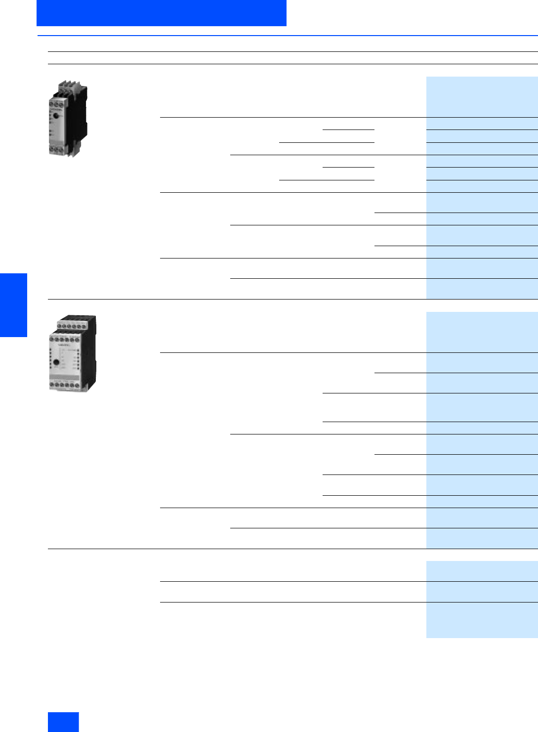
Siemens IK PI · 2004
6/86
AS-Interface Slaves
SlimLine
I/O modules for operation in IP20 control cabinet
6
■
Selection and Ordering data
Design
Order No.
SlimLine S22.5
3RK1 200-0CE00-0AA2
SlimLine S22.5 module
Inputs: PNP transistor
Type Connection
terminals Slave
type Inputs Outputs
4 inputs Screw-type Standard 2-wire --
3RK1 200-0CE00-0AA2
2- and 3-wire
3RK1 200-0CE02-0AA2
A/B slave 2- and 3-wire
3RK2 200-0CE02-0AA2
Cage Clamp Standard 2-wire --
3RK1 200-0CG00-0AA2
2- and 3-wire
3RK1 200-0CG02-0AA2
A/B slave 2- and 3-wire
3RK2 200-0CG02-0AA2
2 inputs/2 outputs Screw-type Standard 2-wire PNP transistor
2 A
3RK1 400-0BE00-0AA2
Relay
3RK1 402-0BE00-0AA2
Cage Clamp Standard 2-wire PNP transistor
2 A
3RK1 400-0BG00-0AA2
Relay
3RK1 402-0BG00-0AA2
4 outputs Screw-type Standard -- PNP transistor
1 A
3RK1 100-1CE00-0AA2
Cage Clamp Standard -- PNP transistor
1 A
3RK1 100-1CG00-0AA2
SlimLine S45
3RK1 400-1CE00-0AA2
SlimLine S45 module
Inputs: PNP transistor
Type Connection
terminals Slave
type Inputs Outputs
4 inputs/4 outputs Screw-type Standard 2- and 3-wire PNP transistor
1 A
3RK1 400-1CE00-0AA2
PNP transistor
2 A
3RK1 400-1CE01-0AA2
2- and 3-wire
floating PNP transistor
1 A
floating
3RK1 402-3CE01-0AA2
2- and 3-wire Relay
3RK1 402-3CE00-0AA2
Cage Clamp Standard 2- and 3-wire PNP transistor
1 A
3RK1 400-1CG00-0AA2
PNP transistor
2 A
3RK1 400-1CG01-0AA2
2- and 3-wire
floating PNP transistor
1 A floating
3RK1 402-3CG01-0AA2
2- and 3-wire Relay
3RK1 402-3CG00-0AA2
4 inputs/ 3 outputs Screw-type A/B slaves 2- and 3-wire PNP transistor
2 A
3RK2 400-1FE00-0AA2
Cage Clamp A/B slaves 2- and 3-wire PNP transistor
2 A
3RK2 400-1FG00-0AA2
Accessories
Sealable cap
For protection against unauthorized addressing
3RP1 902
Plug-in lugs
For screw mounting
3RP1 903
SlimLine opening tool
For all units with Cage Clamp terminals
up to max. 1.5 mm2 conductor cross-section
partly insulated
8WA2 807
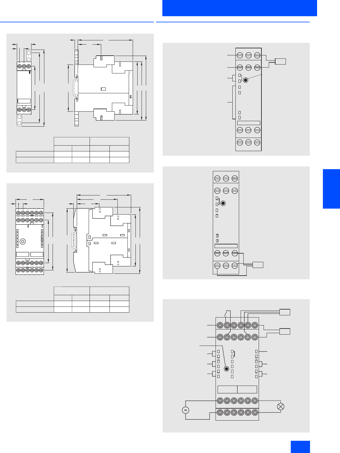
Siemens IK PI · 2004 6/87
AS-Interface Slaves
I/O modules for operation in IP20 control cabinet
SlimLine
6
■
Dimensional drawings
SlimLine S22.5
SlimLine S45
■
Schematics
Typical circuit diagram for SlimLine S22.5
3RK1 200-0CE00-0AA2
3RK1 200-0CE02-0AA2
Typical circuit diagram for SlimLine S45
4 7
45
NSB0_01412
102
536
65
86
A
C
68
92
Standard terminal Removeable terminal
Screw-type terminal
Spring-type terminal
A
84 108
C
83 106
A
84.3 107.6
C
81 104
N S B 0 _ 0 1 4 1 3
A
B
C
7 4
8 6
5
3 6
1 2 0
1 1 0 x 1 5
6 8
4 7
2 2 , 5
4 7
45
NSB0_01412
102
536
65
86
A
C
68
92
Standard terminal Removeable terminal
Screw-type terminal
Spring-type terminal
A
84 108
C
83 106
A
84.3 107.6
C
81 104
N 2
N 3
N 4
A S - i
A D D R
++
N 3 N 4
A S - i -
A S - i + N 1 N 2
N S A 0 _ 0 0 3 2 7
+ +
N 1
A S - i -
A S - i +
O U T
123
456
789
1 0 1 1 1 2
+
A d d r e s s i n g
s o c k e t
L E D ' s f o r c o m m u n i c a t i o n
L E D ' s f o r i n p u t s 1 - 4
2 - w i r e
s e n s o r
N 2
N 3
N 4
A S - i
A D D R
++
I N 3 I N 4
A S - i -
A S - i + N 1 N 2
N S A 0 _ 0 0 3 2 8
- +
N 1
123
456
789
1 0 1 1 1 2
-
-
O U T
+
-
3 - w i r e
s e n s o r
A S - i - + + + +
-
1 4 5 6
23
7 1 0 1 1 1 2
89
A S - i + I N 1 I N 2 I N 3 I N 4
-
1 3 1 6 1 7 1 8
1 4 1 5
1 9 2 2 2 3 2 4
2 0 2 1
M 2 4 - - - -
L 2 4 + O U T 1 O U T 2 O U T 3 O U T 4
A S - i
I N 1
I N 2
O U T 1
O U T 2
I N 3
I N 4
O U T 3
O U T 4
A D D R
A U X P O W E R
O U T
+
S e n s o r 3 - L ( P N P )
-
O U T
+
S e n s o r 2 - L ( P N P )
-
+
-
A U X P O W E R 2 4 V D C +
-
A S - i -
A S - i +
N S A 0 _ 0 0 3 2 9
L E D ' s f o r i n p u t 3 - 4
L E D A U X P O W E R
a v a i l a b l e
L E D ' s f o r o u t p u t s 3 - 4
C o n s u m e r
M e c h a n i c a l
s w i t c h e s
A d d r e s s i n g s o c k e t
L E D ' s f o r c o m m u n i c a t i o n
L E D ' s f o r i n p u t 1 - 2
L E D ' s f o r o u t p u t s 1 - 2
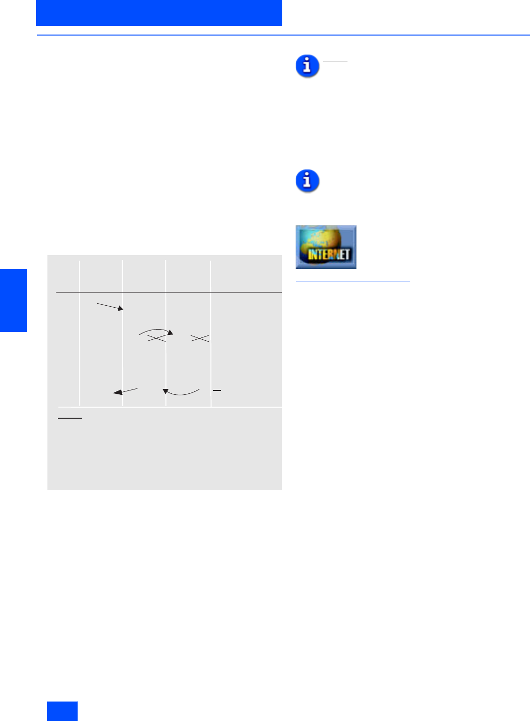
Siemens IK PI · 2004
6/88
AS-Interface Slaves
Module F90
I/O modules for operation in IP20 control cabinet
6
■
Function
Principle of operation of the 16E module (3RG9 002-0DE00
and 3RG9 004-0DE00)
The 16 inputs are arranged in four groups of four inputs.
Only one group is permitted to be activated at a time. The PLC
activates each group in sequence and reads the four input sig-
nals into the process image of the inputs in each case. The user
program assigns the input information to the appropriate
groups, i .e. the output process image of the PLC must corre-
spond to the set output of the module otherwise input information
will be read in from the wrong group.
When a fault occurs in AS-i transmission, it can take up to three
AS-i cycles (15 ms) until the output image of the slave corre-
sponds to the output image of the master and therefore of the
PLC. It can also take three cycles to transfer the input image of
the slave. If messages to a particular slave are faulty over more
than three consecutive AS-i cycles, the slave outputs a "Config
error" to the master. The input image in the master is set to zeroes
and the fault bit is set in the PLC.
Example: Response of the output image and the input image
in the master and in the slave to faulty AS-Interface transfer
The example shows that the output image and input image are
not consistent in the master and slave until six AS-Interface
cycles have elapsed. The PLC cycle is not synchronous with the
AS-Interface cycle. For this reason, the time that must elapse be-
fore the output image and input image of the master and PLC are
consistent is extended by one AS-Interface cycle and one PLC
cycle respectively.
Formula for the cycle time:
4 · ((6 · 5 ms) + 5 ms + 10 ms) =180 ms
Note 1:
The following function blocks (FBs) are available for
sequence control:
•FB 21 (E16-2433) for the AS-Interface master CP2433
(S5-95 U)
•FB 22 (E16-2430) for the AS-Interface master CP2430
(S5-115 U)
•FC 22 for S7
At least 30 ms must elapse between two function block calls for
a module to ensure that the switching status of the inputs can be
reliably read.
Note 2:
Programming examples can be requested from out
Technical Support, Tel. (+49 91 31) 74 38 33, or down-
loaded from the Internet:
Additional information is available from in the Internet under:
http://www.siemens.de/as-interface
NSA0_00321
AS-
Inter-
face-
cycle
PLC Master Module Note
PIQ PII QI QI II
1000 xxxx
1 1000 xxxx 0111 xxxx xxxx xxxx fault in MC or SR
2 1000 xxxx 0111 xxxx xxxx xxxx fault in MC or SR
3 1000 xxxx 0111 EEEE 1000 EEEE I invalid because of
switchover time in modu
4 1000 xxxx 0111 xxxx 1000 EEEE fault in MC or SR
5 1000 xxxx 0111 xxxx 1000 EEEE fault in MC or SR
6 1000 xxxx 0111 EEEE 1000 EEEE no fault in MC or SR
1000 EEEE 0111
Legend:
QI Output image
II Input image
MC Master call
PIQ Process image of the outputs
PII Process image of the inputs
SR Slave response
PLC Programmable logic controller
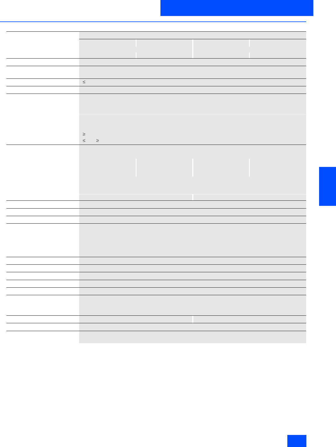
Siemens IK PI · 2004 6/89
AS-Interface Slaves
I/O modules for operation in IP20 control cabinet
Module F90
6
■
Technical specifications
4 inputs/4 outputs
1 A 2 A 1 A 2 A
screw-type terminals Combicon connection
3RG9 002-0DB00 3RG9 002-0DA00 3RG9 004-0DB00 3RG9 004-0DA00
Slave type Standard slaves
Operational voltage in accordance
with AS-Interface specification in V 26.5 to 31.6
Total current input in mA 270
Input connection PNP
Inputs
• Sensor supply via AS-Interface Short-circuit and overload proof
• Voltage range in V 20 to 30
• Load rating for sensor supply in
mA 200
• Connection of sensors 2- and 3-wire system
• Switching level High in V 10
• Input current Low/High in mA 1.5 / 5
Outputs
• Type of output Electronics
• Current carrying capacity in A
DC 12 / DC 13 typ. 1 2 1 2
• Total current of all outputs in A 4 6 4 6
• Short-circuit protection Built-in
• Inductive interference protection
(free-wheeling diode) Built-in
• External voltage supply 24 V DC Built-in via terminal screws Built-in via Combicon male connector
Watchdog Built-in
I/O configuration 7
ID/ID2 code 0/F
Assignment of data bits
•Data bit D0 IN1/OUT1
•Data bit D1 IN2/OUT2
•Data bit D2 IN3/OUT3
•Data bit D3 IN4/OUT4
AS-Interface certificate Yes
Approvals UL, CSA, ship building
Degree of protection IP20
Ambient temperature in °C -25 to +70
Storage temperature in °C -40 to +85
Displays
• Inputs/outputs Yellow LEDs
• AS-I voltage Green LED
Connection Via screw terminal Via Combicon pin connector
Addressing An integrated addressing socket can be used
Note To supply the output circuit, an external supplementary supply (AUX POWER) of 20 to 30 V DC is necessary.
The supplementary supply must comply with VDE 0106 (PELV), safety class III.

Siemens IK PI · 2004
6/90
AS-Interface Slaves
Module F90
I/O modules for operation in IP20 control cabinet
6
■
Technical specifications (continued)
4 inputs/4 outputs
2 A, floating
screw-type terminals Combicon connection
3RG9 002-0DC00 3RG9 004-0DC00
Slave type Standard slaves
Operational voltage in accordance
with AS-Interface specification in V 26.5 to 31.6
Total current input in mA 30
Input connection PNP
Inputs
• Sensor supply via AS-Interface Short-circuit and overload proof
• Voltage range in V 20 to 30
• Load rating for all inputs in mA 200
• Connection of sensors 2- and 3-wire system
• Switching level High in V 10
• Input current Low/High in mA 1.5 / 5
Outputs
• Type of output Electronics
• Current carrying capacity in A
DC 12 / DC 13 typ. 2
• Total current of all outputs in A 6
• Short-circuit protection Built-in
• Inductive interference protection
(free-wheeling diode) Built-in
• External voltage supply 24 V DC Via screw terminal Via Combicon pin connector
Watchdog Built-in
I/O configuration 7
ID/ID2 code 0/F
Assignment of data bits
•Data bit D0 IN1/OUT1
•Data bit D1 IN2/OUT2
•Data bit D2 IN3/OUT3
•Data bit D3 IN4/OUT4
AS-Interface certificate Yes
Approvals UL, CSA, ship building
Degree of protection IP20
Ambient temperature in °C -25 to +70
Storage temperature in °C -40 to +85
Displays
• Inputs/outputs Yellow LED
• AS-i voltage Green LED
Connection Via screw terminal Via Combicon pin connector
Addressing An integrated addressing socket can be used
Note 1 The module has four floating inputs and four floating switching outputs. For the input and output circuits,
an external additional supply of 20 to 30 V according to VDE 0106 (PELV) safety class III is required.
Note 2 To supply the output circuit, an external supplementary supply (AUX POWER) of 20 to 30 V DC is necessary.
The supplementary supply must comply with VDE 0106 (PELV), safety class III.

Siemens IK PI · 2004 6/91
AS-Interface Slaves
I/O modules for operation in IP20 control cabinet
Module F90
6
■
Technical specifications (continued)
16 inputs
Screw-type terminals Combicon connection
Transistor PNP
3RG9 002-0DE00 3RG9 004-0DE00
Slave type Standard slaves
Operational voltage in accordance
with AS-Interface specification in V 26.5 to 31.6
Total current input in mA 70
Input connection PNP
Inputs
• Sensor supply via AS-Interface Short-circuit and overload proof
• Voltage range in V 20 to 30
• Connection of sensors Mechanical contacts
•Signal 1 Uin 20 to 30 V 3 mA
Group signal
• Current carrying capacity Iout 25 mA
• Output voltage Uout 20 to 30 V
Watchdog Built-in
I/O configuration 7
ID/ID2 code F/F
Assignment of data bits
•Data bit D0 Group signal G1 (D0)
Inputs I 1.1 to I 1.4 (D0 to D3)
•Data bit D1 Group signal G2 (D1)
Inputs I 2.1 to I 2.4 (D0 to D3)
•Data bit D2 Group signal G3 (D2)
Inputs I 3.1 to I 3.4 (D0 to D3)
•Data bit D3 Group signal G4 (D3)
Inputs I 4.1 to I 4.4 (D0 to D3)
AS-Interface certificate Yes
Approvals UL, CSA, ship building
Degree of protection IP20
Ambient temperature in °C -25 to +70
Storage temperature in °C -40 to +85
Displays
• Inputs/outputs Yellow LED
Connection Via screw terminal Via Combicon pin connector
Addressing An integrated addressing socket can be used
Note 1 The module has four input groups. Each input group has four inputs and one group signal for power supply
of the inputs. The input groups are activated separately, whereby the relevant group signal is set by the control.
Then the switching states of the associated inputs are read in.
Note 2 Function block required
Note 3 To supply the output circuit, an external supplementary supply (AUX POWER) of 20 to 30 V DC is necessary.
The supplementary supply must comply with VDE 0106 (PELV), safety class III.
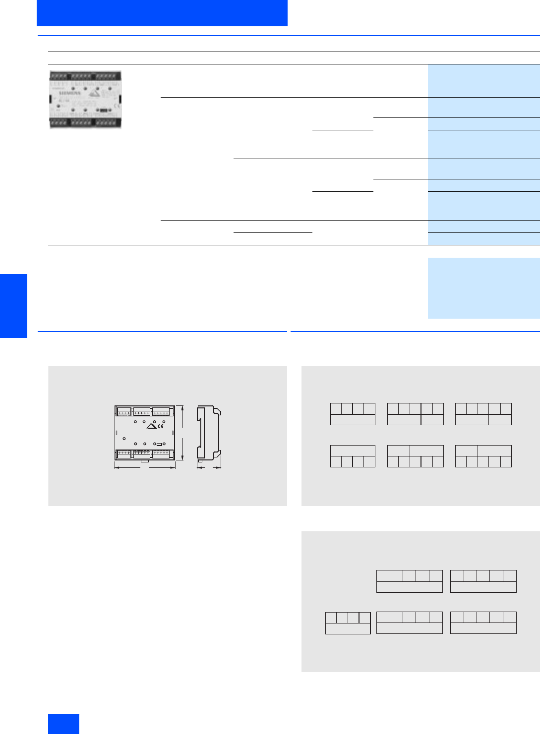
Siemens IK PI · 2004
6/92
AS-Interface Slaves
Module F90
I/O modules for operation in IP20 control cabinet
6
■
Selection and Ordering data
■
Dimensional drawings
■
Schematics
Terminal assignment
3RG9 002-0D.00
3RG9 004-0D.00
3RG9 002-0DE00
3RG9 004-0DE00
Design
Order No.
3RG9 002-0DB00
F90 module
Standard slave
Type Connection Inputs Outputs
4 inputs/4 outputs Screw-type terminals 2- and 3-wire
PNP transistor PNP transistor
1A
3RG9 002-0DB00
PNP transistor
2A
3RG9 002-0DA00
2- and 3-wire
PNP transistor
floating
3RG9 002-0DC00
Combicon 2- and 3-wire
PNP transistor PNP transistor
1A
3RG9 004-0DB00
PNP transistor
2A
3RG9 004-0DA00
2- and 3-wire
PNP transistor
floating
3RG9 004-0DC00
16 inputs Screw-type terminals PNP transistor --
3RG9 002-0DE00
Combicon
3RG9 004-0DE00
Accessories
Combicon connector set
For 4I/4O modules with Combicon connection
One set comprises:
• 4 x 5-pin connector for connecting
• Standard sensors/actuators
• 2 x 4-pin connector for AS-Interface and external auxiliary voltage
3RX9 810-0AA00
9 0
7 5
3 7
N S A 0 0 0 7 4
S I E M E N S
L + L + L - L - E 0 A
UH I I N 1 O U T 1 I N 2 O U T 2
E 0 A
E
0A
O U T 4 I N 4
E
0A
O U T 3 I N 3A S - i
3
2 1
N S A 0 0 0 7 5
1 2 4 7
5 6 8 9 1 0 1 1 1 2 1 3 1 4
1 5 1 6 1 7 1 8 1 9 2 0 2 2 2 3 2 6
2 4 2 5 2 7 2 8
++
++
++
____
_
_
I 1 . 1
A S - i
75 6 8 9 1 0 1 1 1 2 1 3 1 4
G 1 I 1 . 2 I 1 . 3 I 1 . 4
1 5 1 6 1 7 1 8
I 2 . 1G 2 I 2 . 2 I 2 . 3 I 2 . 4
I 3 . 1
2 4 2 5 2 6 2 7 2 8
G 3 I 3 . 2 I 3 . 3 I 3 . 4 I 4 . 1G 4 I 4 . 2 I 4 . 3 I 4 . 4
1 9 2 0 2 1 2 2 2 3
N S A 0 _ 0 0 0 7 6
++
_
_
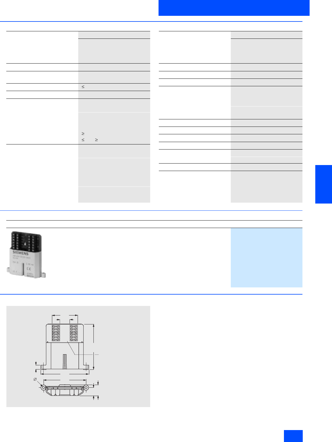
Siemens IK PI · 2004 6/93
AS-Interface Slaves
I/O modules for operation in IP20 control cabinet
Flat module
6
■
Technical Specifications
■
Selection and Ordering data
■
Dimensional drawings
Flat module
4 input/4 outputs
200 mA for all I/Os
screw-type terminals
3RK1 400-0CE00-0AA3
Slave type Standard slaves
Operational voltage in accordance
with AS-Interface specification in V 26.5 to 31.6
Total current input in mA 270
Input connection PNP
Inputs
• Sensor supply via AS-Interface Short-circuit and overload proof
• Voltage range in V 20 to 30
• Load rating for all inputs in mA 200
• Connection of sensors 2- and 3-wire system
• Switching level High in V 10
• Input current Low/High in mA 1.5 / 5
Outputs
• Type of output Electronics
• Current carrying capacity in mA
(DC 12 / DC 13) 200
• Short-circuit protection Built-in
• Inductive interference protection
(free-wheeling diode) Built-in
• External voltage supply DC 24 V Not required
(all inputs and outputs are sup-
plied via the AS-Interface cable)
Flat module
4 input/4 outputs
200 mA for all I/Os
screw-type terminals
3RK1 400-0CE00-0AA3
Watchdog Built-in
I/O configuration 7
ID/ID2 code F/F
Assignment of data bits
• Data bit D0 IN1/OUT1
• Data bit D1 IN2/OUT2
• Data bit D2 IN3/OUT3
• Data bit D3 IN4/OUT4
AS-Interface certificate Yes
Degree of protection IP20
Ambient temperature in °C -25 to +70
Storage temperature in °C -40 to +85
Displays inputs/outputs
• AS-i voltage / FAULT Green LED / red LED
Connection Via screw terminal
Addressing Via an integrated addressing
socket
Design
Order No.
3RK1 400-0CE00-0AA3
Flat module
4 input/4 outputs
200 mA for all I/O
screw terminals
3RK1 400-0CE00-0AA3
n . c .
O U T 3
-
1 8 , 5
1 3 , 5
7 , 5
8 1 , 5
7 9 , 8
1 6 , 5
O U T 1
-
A S i +
n . c .
O U T 4
-
O U T 2
A S i -
-
+
I N 3 I N 4
+
-
-
++
I N 1 I N 2
--
4
4 7 , 5
N S A 0 _ 0 0 0 7 7 a
7 2 , 5
I n t e g r a t e d
a d d r e s s
s o c k e t
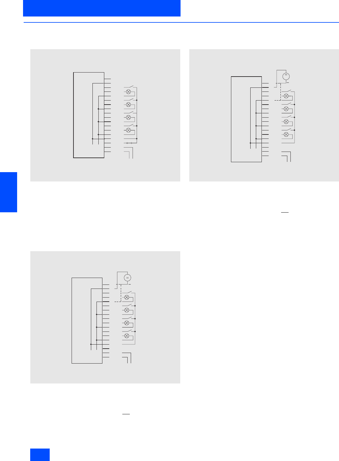
Siemens IK PI · 2004
6/94
AS-Interface Slaves
AS-Interface communication modules
Special integrated solutions
6
■
Overview
AS-Interface communication module for circuit-board
mounting 3RK1 400-0CD00-0AA3
The 4I/4O module for PCB mounting can be used to scan up to
four mechanical contacts or to activate up to four LEDs, whereby
the power is supplied from the AS-i system (yellow AS-Interface
cable).
Note: If the switching outputs are overloaded, the module will not
respond to master calls. Up to 15 addressing procedures are
permitted per module.
AS-Interface communication module for circuit-board
mounting 3RK1 400-0CD01-0AA3
The 4I/4O module for PCB mounting can be used to scan up to
four mechanical contacts or to activate up to four LEDs, whereby
the power is supplied for the inputs and outputs from the auxil-
iary supply (24 V PELV). If (+) is connected to UAux + and (NC)
is connected to UAux -, the outputs will not be short-circuit and
overload proof; if UAux is connected to (0), the outputs will be
overload and short-circuit proof (maximum summation current
200 mA). If the switching outputs are overloaded, the module will
not respond to master calls.
AS-Interface communication module for circuit-board
mounting 3RG9 005-0SA00
The 4I/4O module for PCB mounting can be used to scan up to
four mechanical contacts or to activate up to four LEDs, whereby
the power is supplied for the inputs and outputs from the auxil-
iary supply (24 V PELV). If (+) is connected to UAux + and (NC)
is connected to UAux -, the outputs will not be short-circuit and
overload proof; if UAux is connected to (0), the outputs will be
overload and short-circuit proof (maximum summation current
200 mA). If the switching outputs are overloaded, the module will
not respond to master calls.
+
A S I
A S I +
N S A0_00078a
P R O G
N C
+
I N 1
O U T 1
0
I N 2
O U T 2
0
I N 3
O U T 3
0
I N 4
O U T 4
0
U
+
N S A0_00079a
H i l f
N C
+
I N 1
O U T 1
0
I N 2
O U T 2
0
I N 3
O U T 3
0
I N 4
O U T 4
0
+
A S I
A S I +
U
+
N S A0_00080a
H i l f
N C
+
I N 1
O U T 1
0
I N 2
O U T 2
0
I N 3
O U T 3
0
I N 4
O U T 4
0
+
A S I -
A S I +

Siemens IK PI · 2004 6/95
AS-Interface Slaves
Special integrated solutions
AS-Interface communication modules
6
■
Overview (continued)
AS-Interface communication module for circuit-board
mounting 3RK1400-1CD00-0AA2
1) Note: For pad numbering, see the Section Dimensional Drawings
Via the 4I/4O module for PCB mounting, up to four mechanical
switches or 3-wire sensors to IEC 947-5-2 can be connected or
indicator lamps can be controlled, whereby the short-circuit-
proof electronic switching outputs are supplied from an auxiliary
voltage (24 V PELV).
It is mounted easily via a "Card edge board-to-board-connec-
tor“. This can be ordered, for example, from the company AMP
for vertical and horizontal mounting:
• 180° version for vertical mounting (from AMP):
Order No. 530843-2
• 90° version for horizontal mounting (from AMP):
Order No. 650118-1
If the inputs are loaded with more than 200 mA, the module will
not respond to master calls.
AS-Interface communication module for circuit-board
mounting 3RK1200-0CD00-0AA2
1) Note: For pad numbering, see the Section Dimensional Drawings
Via the 4I module for PCB mounting, up to four mechanical
switches or 3-wire sensors can be connected, whereby the in-
puts are supplied from the AS-Interface cable.
It is mounted easily via a "Card edge board-to-board connector“.
This can be ordered for example from the company AMP for ver-
tical and horizontal mounting:
• 180° version for vertical mounting (from AMP):
Order No. 530843-2
• 90° version for horizontal mounting (from AMP):
Order No. 650118-1
If the inputs are loaded with more than 200 mA, the module will
not respond to master calls.
Connection Connection pad 1)
ASi+ 27, 29
ASi- 28, 30
Sensor+ 17, 18, 23, 24
Sensor- 13, 14, 19, 20
IN1 21
IN2 22
IN3 15
IN4 16
U Aux + (L24+) 2, 4
U Aux - (M24) 1, 3
OUT1 9
OUT2 10
OUT3 5
OUT4 6
OUT- 7, 8
Unused 11, 12, 25, 26
Connection Connection pad 1)
ASi+ 27, 29
ASi- 28, 30
Sensor+ 17, 18, 23, 24
Sensor- 13, 14, 19, 20
IN1 21
IN2 22
IN3 15
IN4 16
Unused 1, 2, 3, 4, 5, 6, 7, 8, 9,
10, 11, 12, 25, 26

Siemens IK PI · 2004
6/96
AS-Interface Slaves
AS-Interface communication modules
Special integrated solutions
6
■
Technical specifications
4 inputs / 4 outputs 4 inputs
I/O supply via AS-
Interface cable
(max. 200 mA)
I/O supply via external auxiliary voltage
(24 V PELV) Supply of outputs
via external
auxiliary voltage
(24 V PELV)
-
Printed-circuit
board with solder
pins protected by
housing
Printed-circuit
board with solder
pins protected by
housing
Printed-circuit
board for horizon-
tal mounting
Printed-circuit board with gold-plated
direct connector for 30-pin male multi-
point connector for easy mounting with
a direct connector
3RK1 400-0CD00-
0AA3 3RK1 400-0CD01-
0AA3 3RG9 005-0SA00 3RK1 400-1CD00-
0AA2 3RK1 200-0CD00-
0AA2
Slave type Standard slaves Standard slaves Standard slaves Standard slaves Standard slaves
Operating voltage in accordance
with AS-Interface specification in V 26.5 to 31.6 26.5 to 31.6 26.5 to 31.6 26.5 to 31.6 26.5 to 31.6
Total current input in mA 270 25 25 270 270
Input connection PNP PNP PNP PNP PNP
Inputs
• Sensor supply Via AS-Interface Via UAux Via UAux Via AS-Interface
cable Via AS-Interface
cable
• Switching voltage V 20 to 30 20 to 30 20 to 30 20 to 30 20 to 30
• Switching current in mA 3 3 3 – –
Outputs
• Type of output Electronics Electronics Electronics Electronics –
• Load voltage in V 20 to 30 19 to 30 19 to 30 U Aux - 0.8 V –
• Short-circuit protection Built-in Built-in Built-in Built-in –
• Inductive interference protection
(free-wheeling diode) –––Built-in (free-wheel-
ing diode) –
• External 24 V DC supply voltage Via solder pins Via solder pins Via solder pins Via circuit board
contacts –
Summation current for all inputs
and outputs in mA 200 200 200 200 200
I/O configuration 77770
ID/ID2 code 0/F 0/F 0/F 0/F 0/F
Assignment of data bits
•Data bit D0 IN1/OUT1 IN1/OUT1 IN1/OUT1 IN1/OUT1 IN1
•Data bit D1 IN2/OUT2 IN2/OUT2 IN2/OUT2 IN2/OUT2 IN2
•Data bit D2 IN3/OUT3 IN3/OUT3 IN3/OUT3 IN3/OUT3 IN3
•Data bit D3 IN4/OUT4 IN4/OUT4 IN4/OUT4 IN4/OUT4 IN4
Approvals UL, CSA,
ship building UL, CSA,
ship building UL, CSA,
ship building – –
Degree of protection Enclosure IP20
Connection pins
IP00
Enclosure IP20
Connection pins
IP00
IP00 IP00 IP00
Ambient temperature in °C –25 to +70 –25 to +70 –25 to +70 –25 to +70 –25 to +70
Storage temperature in °C –40 to +80 –40 to +80 –40 to +80 –40 to +85 –40 to +85
Display Not available Not available Not available AS-i: green
Fault: red
I/O: yellow
L24+: green
AS-i: green
Fault: red
inputs: yellow
LED status displays –––AS-i
On
On
Flashing
On
Fault
Off
On
On
Flashing
Status
O.K.
No data traffic
Null address
Overload (sensor)
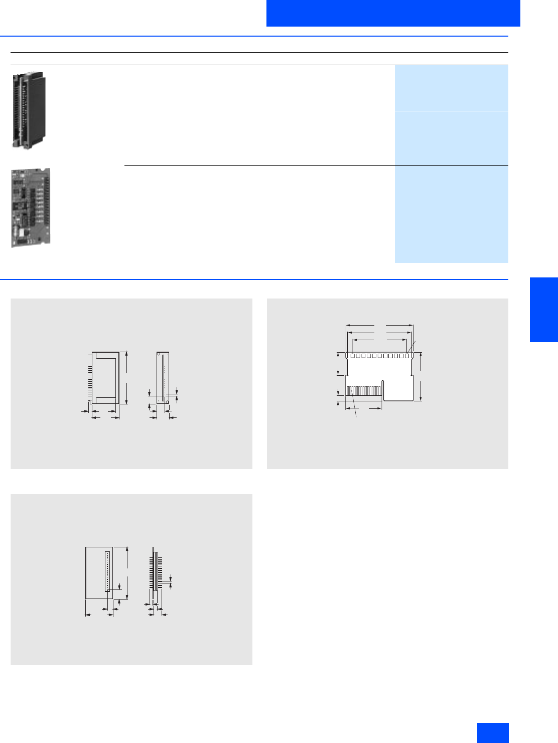
Siemens IK PI · 2004 6/97
AS-Interface Slaves
Special integrated solutions
AS-Interface communication modules
6
■
Selection and Ordering data
■
Dimensional drawings
3RK1 400-0CD00-0AA3
3RK1 400-0CD01-0AA3
3RG9 005-0SA00
3RK1 400-1CD00-0AA2
3RK1 200-0CD00-0AA2
Pad numbering rear side: 29, 27, 25, to , 5, 3, 1
Pad numbering rear side: 30, 28, 26, to , 6, 4, 2
Design
Order No.
3RK1 400-0CD00-0AA3
3RG9 005-0SA00
4 inputs / 4 outputs
• I/O supply via AS-Interface cable (max. 200 mA)
Printed-circuit board with solder pins protected by a housing
3RK1 400-0CD00-0AA3
• I/O supply via external auxiliary voltage (24 V PELV)
- Printed-circuit board with solder pins protected by a housing
3RK1 400-0CD01-0AA3
- Printed-circuit board with solder pins for horizontal mounting
3RG9 005-0SA00
• Outputs supplied via external auxiliary voltage (24 V PELV)
Printed-circuit board with gold plated direct connector for 30-pole plug
connector for easy installation with direct connector
3RK1 400-1CD00-0AA2
4 inputs
Printed-circuit board with gold plated direct connector for 30-pole plug
connector for easy installation with direct connector
3RK1 200-0CD00-0AA2
7 5
3 8
4 0
1 2 , 1
2 0
9
2 , 5 4
N S A 0 0 0 8 1
6
7 3
3 7 , 8 6
2 , 5 4
N S A 0 0 0 8 3
2 , 3
2 0 , 6
3 , 9 9 , 3
54
75
6
60
71
40 NSA0_00343
AS-i
Fault
IN1
IN2
IN3
IN4
OUT1
UOT2
OUT3
OUT4
AUX-PWR
25.5
(Grid 10 x 6 mm)
Light
emitted
on top
Height
9 mm
Connector (gold-plated) for
edge-socket connector
e.g. from AMP 1-0100317-5
(30-pole)
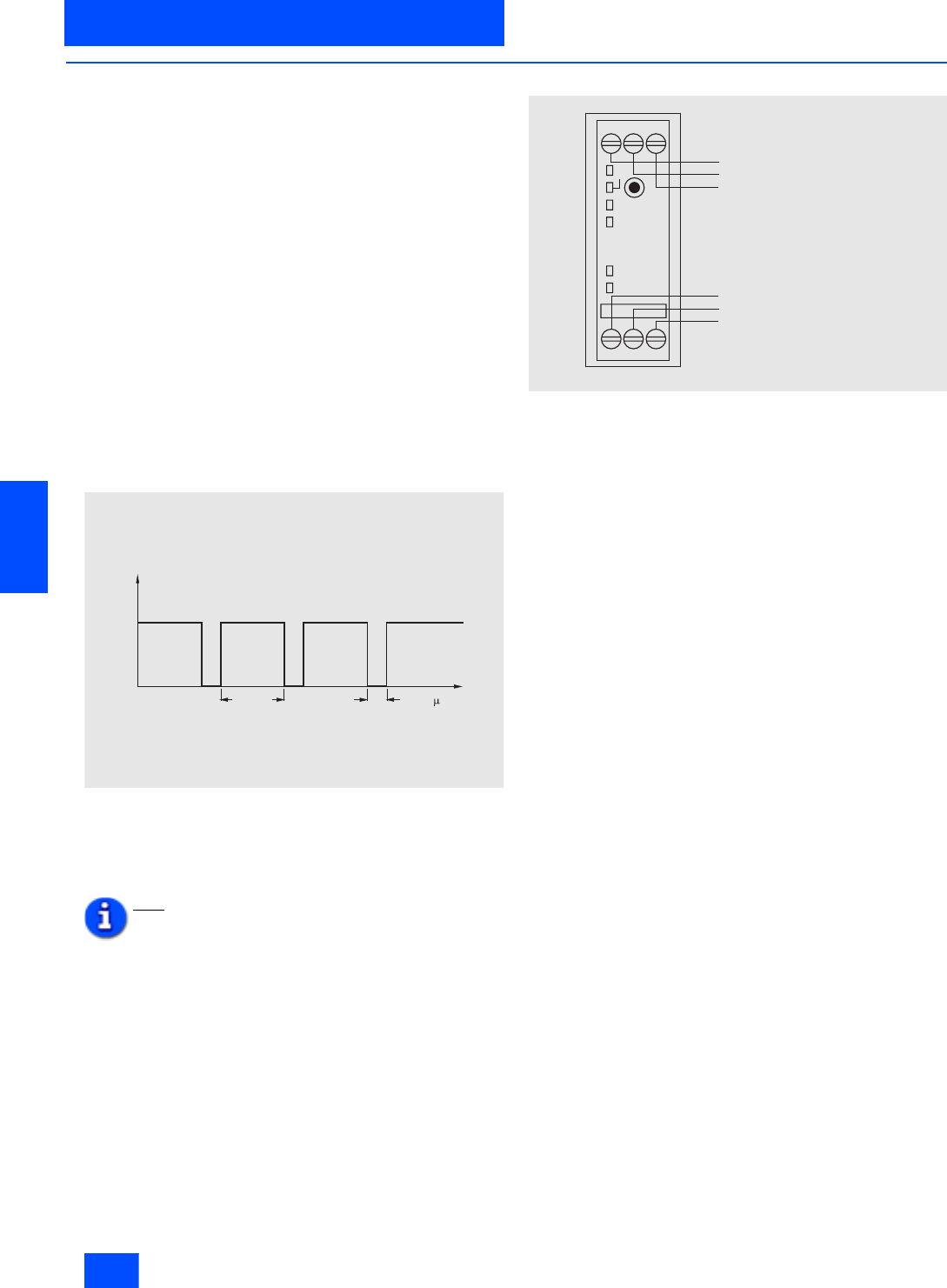
Siemens IK PI · 2004
6/98
AS-Interface Slaves
Counter modules
Modules with special functions
6
■
Overview
This module is used to transfer hexadecimal coded counter val-
ues (LSB=D0, MSB=D3) to a higher-level controller. Each valid
count pulse on terminal 8 causes the counter value to be incre-
mented. The module counts from 0 up to 15 and then starts
again at 0. The control system then loads the current value and
determines the number of pulses between two host calls by gen-
erating the difference. The total number of counter pulses is de-
termined by summation of these differences.
To ensure that valid values are transferred, no more than 15
count values must be applied to terminal 8 between two host or
ASI master calls. The maximum permissible transfer frequency
is calculated as follows from these times:
fTmax = 15 / Tmax
Tmax: Maximum possible transfer time from slave to host.
Another restriction on the maximum frequency is the required
pulse shape. To ensure that the counter loads a pulse as valid,
a low value must be applied to the input for at least 300 µs, while
a high value must be applied for at least 1 ms. This results in a
maximum frequency for the counter module independent of the
controller of
fFCmax = 1 / 1.3 ms = 769 Hz for the counter module
(see diagram nsa00084).
In the event of non-compliance with the time criterion shown in
the adjacent diagram, the counter value is rejected.
The counter is only active for the reset parameter P2 (default). By
setting P2, the counter is erased, but incoming pulses are only
registered when P2 has been reset.
Note:
A customer-specific function block is required
or must be programmed.
Typical connections
N S A 0 0 0 8 4
U
I N 1
³
1 m s
³
3 0 0 s t
N S A 0 _ 0 0 0 8 5
I N 1
A S i
A D D R
A S i + A S i -
I N 1 -
+
T e r m i n a l 4 : B u s c o n n e c t i o n A S i +
T e r m i n a l 5 : B u s c o n n e c t i o n A S i -
T e r m i n a l 6 : u n u s e d
T e r m i n a l 7 : S e n s o r s u p p l y +
T e r m i n a l 8 : C o u n t e r i n p u t
T e r m i n a l 9 : S e n s o r s u p p l y -
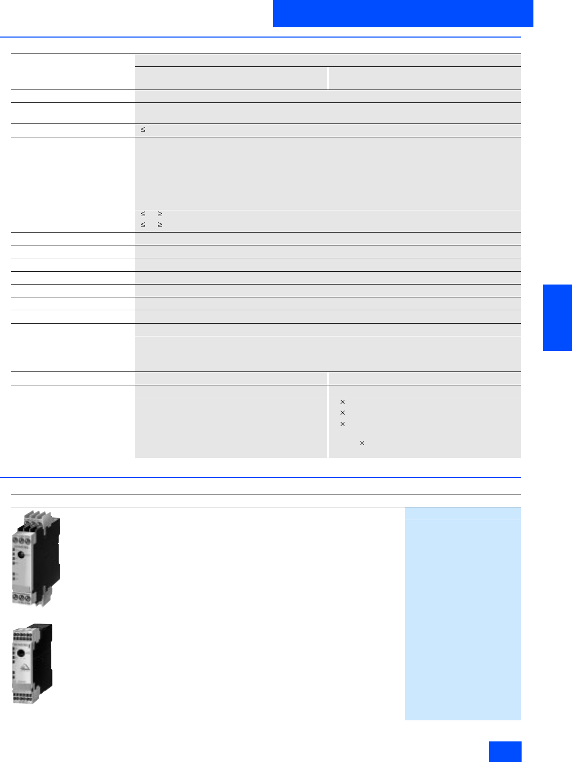
Siemens IK PI · 2004 6/99
AS-Interface Slaves
Modules with special functions
Counter modules
6
■
Technical specifications
■
Selection and Ordering data
Counter modules
With screw-type terminal connection With Cage Clamp terminal connection
3RK1 200-0CE03-0AA2 3RK1 200-0CG03-0AA2
Slave type Standard slaves
Operational voltage in accordance
with AS-Interface specification in V 26.5 to 31.6
Total current input in mA 170
Input
• Sensor supply via AS-Interface Short-circuit and overload proof
• Assignment Terminal 7 = +
Terminal 9 = -
Terminal 8 = IN1
• Voltage range in V 20 to 30
• Current carrying capacity in mA 90
• Switching level Low/High in V 5 / 10
• Input current Low/High in mA 2 / 10
I/O configuration 0
ID code F
AS-Interface certificate Yes
Approvals UL, CSA, ship building
Degree of protection IP20
Ambient temperature in °C -25 to +70
Storage temperature in °C -40 to +85
Displays
•AS-i Green LED on + red LED off = status O.K.
Green LED off + red LED on = no data traffic
Green LED flashing + red LED on = null address
Green LED off + red LED flashing = overload (sensor)
Connection Screw terminals Cage Clamp terminals
Conductor cross-sections in mm2
• Solid -- 2 (0.25–1.5)
• Finely standed with end sleeve -- 2 (0.25–1)
• Finely stranded without end
sleeves -- 2 (0.25–1.5)
• AWG conductors,
solid or stranded -- AWG 2 (24–16)
Design
Order No.
3RK1 200-0CE03-0AA2
3RK1 200-0CG03-0AA2
Counter module
• with screw terminals
3RK1 200-0CE03-0AA2
• with Cage Clamp terminals
3RK1 200-0CG03-0AA2
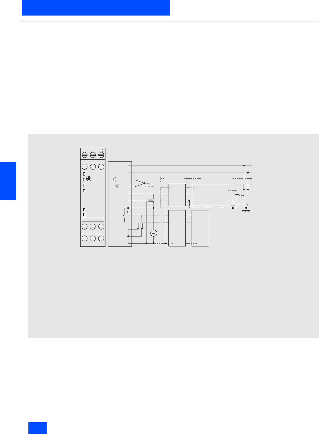
Siemens IK PI · 2004
6/100
AS-Interface Slaves
Earth fault detection modules
Modules with special functions
6
■
Overview
"... Earth faults in control circuits should neither lead to uninten-
tional start-up nor to dangerous motion of a machine and they
must not hinder shutdown of the machine (EN 60204, Part 1 or
DIN VDE 0113)".
The AS-Interface earth-fault detection module has been devel-
oped to ensure that these requirements can be met more easily
in the future. This module from the SlimLine Series allows earth
faults in AS-Interface installations to be reliably detected and re-
ported.
The following earth faults are detected:
• Earth fault in AS-i "+"
• Earth fault in AS-i "-"
• Earth fault in sensors and actuators that are supplied from the
AS-Interface voltage
In each case, only one module is necessary for each AS-Inter-
face network.
■
Function
The earth fault is detected by the module, indicated via a LED
and signaled via two signaling outputs (1 = no earth fault /OK;
2 = earth fault/fault. The earth fault alarm is stored in the module.
The module can only be reset after the earth fault has been rec-
tified by switching off the AS-Interface voltage via a reset button
or via a high signal on the floating remote-reset input. The reset
button can also be used for checking correct functioning of the
module. External auxiliary voltages are not monitored for earth
faults by this module.
Note: The earth fault detection module is a passive module with-
out an IC. Therefore it does not require an individual address in
the AS-Interface network.
Typical connections
N S A 0 _ 0 0 0 9 0 a
P E
P E
5 k 6
5 k 6
2 4 V
1 / A S - i -
4 / A S - i +
2 /
3 / T
3 / R
R E S
6 / -
7 / L 2 4 +
8 / O K
9 / F A U L T
1 2 / M 2 4
1 1 / M 2 4
1 0 / M 2 4
+ +
+
R E SR E S
+
1 / A S - i -
4 / A S - i +
-
R - R E S
O . K .
F A U L T
A S - i
T E S T /
RESET
M 2 4 M 2 4 M 2 4
L 2 4 + O . K . F A U L T
A S - i - T
A S - i + R - R E S -
-
-
-
RR
O . K . O . K .
F A U L T
F A U L T
A l t e r n a t i v e l y A u t o m a t i c t e s t
P L CP L C
I n p u t
I n p u t
I n p u t
I n p u t
O u t p u t
P L C
O u t p u t
O u t p u t
A S - i f a u l t
O u t p u t
A S - i f a u l t
P L C
A S - i c o n n e c t i o n
C o n n e c t i o n f o r s y s t e m e a r t h
C o n n e c t i o n f o r s y s t e m e a r t h ( f o r t e s t f u n c t i o n )
A s - i + c o n n e c t i o n
R e m o t e r e s e t i n p u t ( R - R E S )
R e m o t e r e s e t g r o u n d ( )
E x t e r n a l v o l t a g e s u p p l y f o r s i g n a l i n g o u t p u t s L 2 4 +
S i g n a l i n g o u t p u t O . K .
S i g n a l i n g o u t p u t F A U L T ( e a r t h f a u l t s i g n a l i n g )
E x t e r n a l v o l t a g e s u p p l y f o r s i g n a l i n g o u t p u t s M 2 4
N e g a t i v e c o n n e c t i o n f o r s i g n a l i n g o u t p u t M 2 4
N e g a t i v e c o n n e c t i o n f o r s i g n a l i n g o u t p u t M 2 4
1
2
3
4
5
6
7
8
9
1 0
1 1
1 2
T e r m i n a l D e s i g n a t i o n

Siemens IK PI · 2004 6/101
AS-Interface Slaves
Modules with special functions
Earth fault detection modules
6
■
Technical specifications
1) UAux should be protected with a slow-action 2 A fuse.
2) For increasing the relay endurance with inductive loads,
a protective circuit with free-wheeling diodes is recommended.
Earth fault detection module
With screw-type terminal connection With Cage Clamp terminal connection
3RK1 408-8KE00-0AA2 3RK1 408-8KG00-0AA2
Total current input in mA 40
Polarity reversal protection Built-in
Earth fault 10% UAS-i UGND 90% UAS-i
Low signal range
•I IN in mA 1.5
High signal range
•U IN in V 10
•I IN in mA 6
Current carrying capacity 1)
•DC 12 in A 1 (max. 2 per module)
•DC 13 in A 500 (24 V)2)
•DC 13 in mA 200 (48 V)2)
Operating cycles DC 12 2 106
Rated operating voltage range in V 24 to 48 DC
Degree of protection IP20
Dimensions (H x W x D) in mm 102 22.5 92
Rated temperature in °C 25
Ambient temperature in °C -25 to +70
Storage temperature in °C -40 to +85
Addressing The module does not require an individual AS-Interface address
Connection Screw-type terminal connection Spring-loaded terminal connection
Conductor cross-sections in mm2
• Solid -- 2 (0.25–1.5)
• Finely stranded with end sleeve -- 2 (0.25–1)
• Finely stranded without end
sleeves -- 2 (0.25–1.5)
• AWG conductors,
solid or stranded -- AWG 2 (24–16)
Note If repeaters are used, each AS-Interface segment needs its own earth fault detection module
(number of AS-Interface power supply units = number of earth fault detection modules)
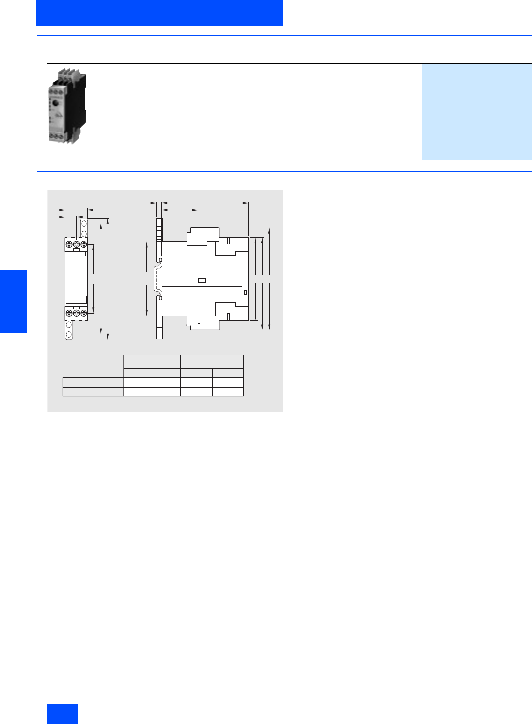
Siemens IK PI · 2004
6/102
AS-Interface Slaves
Earth fault detection modules
Modules with special functions
6
■
Selection and Ordering data
■
Dimensional drawings
Design
Order No.
3RK1 408-8KE00-0AA2
Earth fault detection module
• with screw terminals
3RK1 408-8KE00-0AA2
• with Cage Clamp terminals
3RK1 408-8KG00-0AA2
4 7
45
NSB0_01412
102
536
65
86
A
C
68
92
Standard terminal Removeable terminal
Screw-type terminal
Spring-type terminal
A
84 108
C
83 106
A
84.3 107.6
C
81 104
N S B 0 _ 0 1 4 1 3
A
B
C
7 4
8 6
5
3 6
1 2 0
1 1 0 x 1 5
6 8
4 7
2 2 , 5
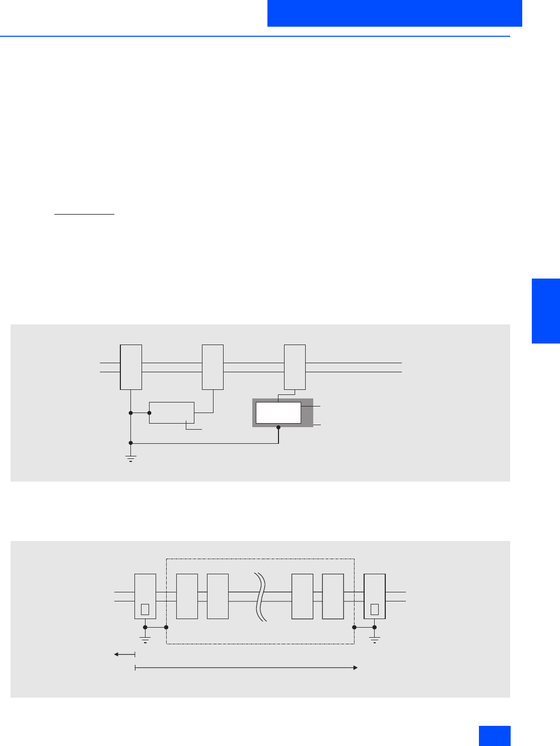
Siemens IK PI · 2004 6/103
AS-Interface Slaves
Modules with special functions
Overvoltage protection module
6
■
Overview
The AS-Interface overvoltage protection module protects down-
stream AS-Interface devices or individual sections of the instal-
lation in AS-Interface networks from conducted overvoltage
caused by switching procedures and distant lightning strikes.
The installation site of the overvoltage protection module repre-
sents the transition from Zone 1 to 2/3 within the lightning protec-
tion zone concept. Direct lightning strikes must be overcome by
means of additional protective measures at the transitions from
lightning protection Zone 0A to 1.
The AS-Interface overvoltage protection module enables the AS-
Interface to be integrated into the overall overvoltage protection
concept of a plant or machine.
The module has the same design, connection and degree of
protection (IP67) as the previous AS-Interface application mod-
ules. It is a passive module without an AS-i IC and therefore does
not require its own address on the AS-Interface network.
It is connected to an AS-Interface system via the FK-E or PG-E
coupling module. The EEMS interface can be used to protect the
AS-Interface cable and the auxiliary voltage cable against over-
voltage.
Overvoltages are diverted via a ground cable with a yel-
low/green oil-proof outer casing. This cable is permanently inte-
grated into the module and must be connected to system earth
with a low resistance connection.
Nominal discharge current isn
The nominal discharge current is the peak value of a peak cur-
rent with an 8/20 microsecond waveform for which the overvolt-
age protection module is rated in accordance with a specific test
program.
With the 8/20 waveform, 100% of the value is reached after
8 microseconds and 50% of the value is reached after 20 micro-
seconds.
Protection level Up
The protection level of an overvoltage protection module is the
highest instantaneous voltage value at the terminals which is
determined from individual tests.
The protection level characterizes the capability of an overvolt-
age protection module to limit overvoltages to a residual level
Accessories
An FK-E or PG-E coupling module is required to connect the
AS-Interface cable and the auxiliary voltage supply cable.
Installation guidelines
Earthing of the protective modules and of the devices to be
protected must be carried out via a common grounding point
(equipotential bonding). If devices with total insulation are to be
protected, their mounting brackets must also be connected into
the grounding points.
Application example
NSA0_00093
AS-
Inter-
face
AS-
Inter-
face
Application Device without earth connection
®
Earthing of the mounting plate
Mounting plate
Device with
earth connection
Application
OVP
OVP = Overvoltage protection
AS-
I n t e r -
f a c e
N S A0_00092
A
AS-
I n t e r -
f a c e B
AS-
I n t e r -
f a c e
AS-
I n t e r -
f a c e
Z o n e 2
p r o t e c t e d r a n g e
E q u i p o t e n t i a l b o n d i n g
( s y s t e m e a r t h )
Z o n e 1 Z o n e 1
P r o t e c t i o n a p p r o x . 0 . 5 m t o t h e l e f t
P r o t e c t i o n a p p r o x . 5 m t o t h e r i g h t
O V P O V P
O V P = O v e r v o l t a g e p r o t e c t i o n
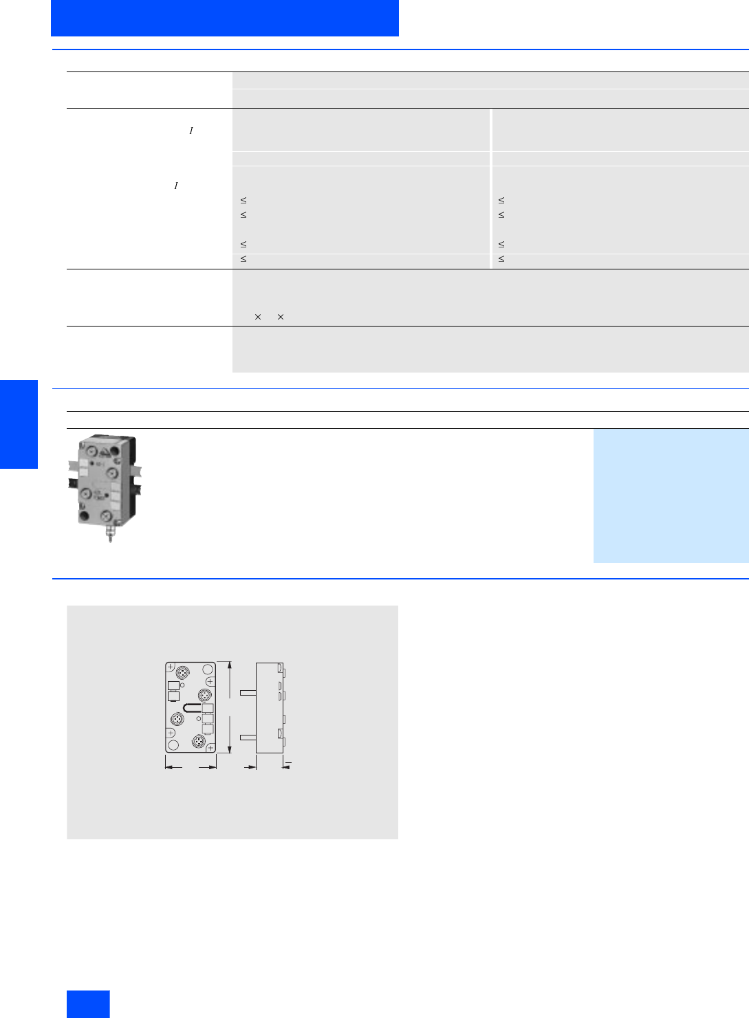
Siemens IK PI · 2004
6/104
AS-Interface Slaves
Overvoltage protection module
Modules with special functions
6
■
Technical specifications
■
Selection and Ordering data
■
Dimensional drawings
Overvoltage protection module
3RK1 901-1GA00
Overvoltage protection for AS-i for AUX power
• Rated discharge current sn for
curve form 8/20
- Core to PE in kA 10 10
- Core to core in kA 0.5 0.5
• Protective level Up at sn
- Core to PE in kV 1.8 1.8
- Core to core in V 100 70
• Protective level Up at 1 kV / µs
- Core to PE in V 700 600
- Core to core in V 50 40
Mechanical data
• degree of protection
(with coupling module) IP67
• Dimensions (H x W x D) in mm 80 45 25
Temperature range
• Ambient temperature in °C -25 to +85
• Storage temperature in °C -40 to +85
Design
Order No.
3RK1 901-1GA00
Overvoltage protection module
3RK1 901-1GA00
N S A 0 0 0 8 7
4 5
8 0
2 5
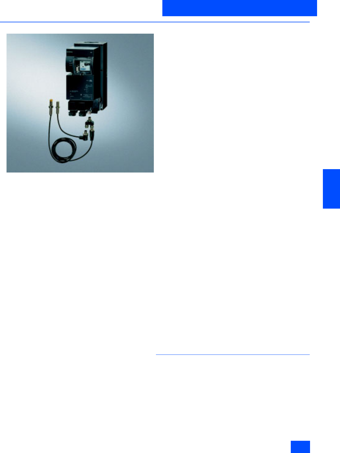
Siemens IK PI · 2004 6/105
AS-Interface Slaves
AS-Interface motor starters and IP65/67 load feeders
AS-Interface compact starters IP65 (400 V AC)
6
■
Overview
The AS-Interface compact starter is a load feeder with degree of
protection IP65, which is fully prewired inside, for switching and
protecting any three-phase loads up to 5.5 kW at 400/500 V AC
(electromechanical compact starter) or up to 2.2 kW (electronic
compact starter) mostly 3-phase standard motors in direct-on-
line and reversing operation. It consists either of an electrome-
chanical controlgear combination or an electronic overload relay
and circuit-breaker unit. The overload or short-circuit protection
is located below a sealable, transparent cover and is therefore
available for diagnosis. Two LEDs are provided to the left of the
cover for diagnostic purposes for the AS-Interface and the aux-
iliary power.
Live parts cannot be touched even when the cover is open.
The control elements are activated via the integrated outputs.
The status of the device is scanned via the inputs, e.g. check-
backs from the auxiliary contacts of the circuit-breaker and con-
tactor(s). A further input is used to detect the operating state of
the optional hand-held terminal. The three power connectors are
used to feed and loop through to the load supply voltage (power
bus) and to connect to the load itself. Prefabricated power sup-
ply lines can be used to connect compact starters which are di-
rectly adjacent to each other. The maximum number of starters
that can be supplied via a power supply cable is limited by the
maximum permissible total current (up to max. 4 mm2 ~ 35 A),
see Technical specifications.
DS/RS compact starters (electromechanical)
The electromechanical compact starters consist of a conven-
tional switchgear combination with a SIRIUS circuit-breaker for
protection against short-circuits and overloading and SIRIUS
contactor(s) for normal switching. The advantages of the electro-
mechanical starters are the reliable isolation during disconnec-
tion and tripping, the integrated fuseless protection against
short-circuits and the favourable price. What is more, direct cur-
rents can also be switched with the electromechanical starters.
Planning information: In the case of temperature-critical applica-
tions, we recommend operation in the lower setting range of the
circuit-breaker.
EDS/ERS compact starters (electronic)
The electronic compact starters EDS (direct starter) and ERS
(reversing starter) consist of an electronic overload relay and an
electronic circuit-breaker unit.
The advantages of these electronic compact starters are the
broad limits within which the overload protection can be ad-
justed (the power range up to 2.2 kW at 400/500 V AC is covered
with just 2 versions), the fact that the electronic contact elements
in the power section are non-wearing, current detection (used
for monitoring the energy connector), emergency operation in
the event of an overload as well as remote resetting via the AS-
Interface after overload tripping.
The ERS compact starter is designed for direct on-line starting
in reversing mode. The electronic overload protection and the
shutdown response in the event of overload can be adjusted di-
rectly at the device.
Version with brake contact
All compact starters are available optionally with a separately
activated brake contact for electrically operated motor brakes.
For externally fed motor brakes, 24 V DC is supplied jointly with
the load voltage via the power connector on -X1. It is looped
through via -X3 for supplying the next compact starter on -X1.
The 24 V DC supply for the brakes is only bridged in those de-
vices equipped with a brake contact. At the project planning
stage, it is important to ensure that these starters are located
alongside each other.
All compact starters with a brake contact for 500 V DC can be
equipped with a 400 V AC brake contact.
Hand-held terminal
The hand-held terminal enables the compact starter to be oper-
ated locally and autonomously, providing that the auxiliary volt-
age supply is connected. Thus, assuming that the automation
level is functioning correctly, local switching operations can be
carried out in addition to normal manual operations in the event
of a programmable controller / bus system failure (emergency
mode) or during test runs before commissioning, e.g. for testing
the direction of rotation of the motor. The hand-held terminal can
be connected to the compact starter by means of a connecting
cable via a socket underneath the transparent cover.
Spare inputs
The compact starters are also equipped with two spare inputs.
The M12 socket is a "Y" connector. The signal inputs are applied
to PIN 2 and 4. In this manner, it is possible for example to con-
nect an optical proximity switch that supplies a signal and the
“fouling” alarm.
A "T" adapter can be used to split the signal inputs onto two M12
sockets. Compact starters modified in this way offer additional
advantages. At no extra cost, it is possible to save AS-i ad-
dresses, reduce the space requirement and to build up logical
groupings.
■
Design
Wiring and assembly
All the connections are either of the plug-in type or use the easy-
installation insulation-piercing method.
The shaped cables for the 24 V auxiliary power supply which is
used to control the contactors as well as the AS-Interface data
cable must simply be inserted in the mounting plate. The com-
pact starter is then cradled in the mounting plate and screwed
tight. The compact starter and the mounting plate must be or-
dered separately. The power for the main circuit is fed in via a
power connector to be ordered separately (see Accessories un-
der Selection and Ordering data).
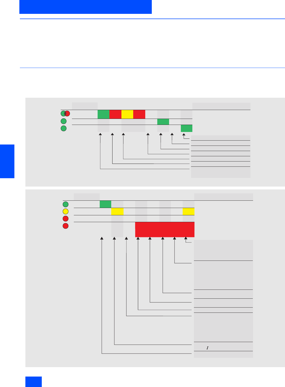
Siemens IK PI · 2004
6/106
AS-Interface Slaves
AS-Interface compact starters IP65 (400 V AC)
AS-Interface motor starters and IP65/67 load feeders
6
■
Design (continued)
The load itself and any other compact starters are supplied us-
ing the same connection technique. All the supply and data ca-
bles can thus be laid through the system like a bus. Whereas the
controlgear is switched via the outputs by the 24 V auxiliary
power supply, the inputs are supplied by the AS-Interface data
cable. This principle of separate auxiliary power supplies facili-
tates selective emergency stop concepts.
Addressing
The addressing of the AS-Interface compact starter can still be
used even if it is fully wired, because the module is disconnected
from the AS-Interface network as soon as the addressing con-
nector is inserted.
■
Function
Display characteristics
Under normal operation, the LEDs on the compact starters indi-
cate the following device states:
LED
AUX PWR
AS-Interface
STATE 1)
NSA0_00322
Status description
Control signal applied
No auxiliary power
Auxiliary power on
No power for slave electronics
Station address 0
AS-Interface communication absent
AS-Interface communication o.k.
On
States
Flash-
ing
On On Flash-
ing Off
On Off
LED
RUN
READY
FAULT
NSA0_00323
OVERLOAD
States Status description
Main circuit on
Rotary coding switch in position
Tripping REMOTE: Continued ope-
ration when programmed in the user
program
Main circuit off
Rotary coding switch in position
Tripping LOCAL: Direct shut-off
Rotary coding switch in position
Tripping REMOTE: Remote shut-off
when programmed in the user
program
Main circuit off
(test finished)
Main circuit off
(test running)
Main circuit on
Main circuit off, e.g. through
Failure of two phases
Drawn motor connector
Supply voltage drop
(< 18 V)
Simultaneous control of clockwise
and anti-clockwise rotation
Main circuit on with conduction
>_ 20% n
Unit ready to operate
On
On Off On
On
Nor-
mal
flash-
ing
Fast
flash-
ing
Slow
flash-
ing
On On

Siemens IK PI · 2004 6/107
AS-Interface Slaves
AS-Interface motor starters and IP65/67 load feeders
AS-Interface compact starters IP65 (400 V AC)
6
■
Function (continued)
Diagnosis of the electronic compact starter with the user
programme
The input and output signals of the DS2E and RS2E electronic
compact starters can be evaluated in the user programme.
Output DO2 is only controlled in those variants with a brake con-
tact.
The I/O assignment corresponds to the AS-Interface motor
starter profile 7D.
Note:
The brake contact is controlled via the bus separately from the
main circuit. This makes it possible to switch the motor and
brake independently. In the user programme, it must be ensured
that dangerous plant states cannot occur, e.g. unintentional free-
wheeling or blocking of the motor. This also applies to local shut-
down, e.g. in response to an overload tripping operation. Input
signal DI0 can be used to check the status of the device.
Inputs
Outputs
Input signals Device status Meaning
DI0 “Ready” 0 Device not ready / error Manual mode
Device has neen switched to manual mode locally
(switch back to automatic mode using hand-held unit).
Overload/short-circuit tripping
The circuit-breaker recloses once a cooling-off period has elapsed.
FAULT signal
• Defective coil.
• Contact welded.
• Output driver defective (contactor must be tested).
• Simultaneous activation of clockwise and counterclockwise rotation
(user programme must be checked).
1Device is ready / automatic
mode –
DI1 “Running” 0 Contactor OFF –
1Contactor ON –
DI2 “Special information 1” 0 No input signal IN1 –
1Input signal IN1 –
DI3 “Special information 2” 0 No input signal IN2 –
1Input signal IN2 –
Output signals Device status Meaning
DO0 “Run forward” 0 Clockwise rotation OFF –
1Clockwise rotation ON –
DO0 “Run reserve” 0 Counterclockwise rotation OFF –
1Counterclockwise rotation ON –
DO2 “Special command 1” 0 Open brake contact –
1Close brake contact –
DO3 “Special command 2” 0 – –
1– –

Siemens IK PI · 2004
6/108
AS-Interface Slaves
AS-Interface compact starters IP65 (400 V AC)
AS-Interface motor starters and IP65/67 load feeders
6
■
Function (continued)
Diagnosis of the electronic compact starter by means of the
user programme
The input and output signals of the EDS2E and ERS2E electro-
mechanical compact starters can be evaluated in the user pro-
gramme.
Output DO2 is only controlled in those variants with a brake con-
tact.
The I/O assignment corresponds to the AS-Interface motor
starter profile 7E.
Note:
The brake contact is controlled via the bus separately from the
main circuit. This makes it possible to switch the motor and
brake independently. In the user programme, it must be ensured
that dangerous plant states cannot occur, e.g. unintentional free-
wheeling or blocking of the motor. This also applies to local shut-
down, e.g. in response to an overload tripping operation. Input
signal DI0 can be used to check the status of the device.
Inputs
Outputs
Input signals Device status Meaning
DI0 „Ready“ 0 Device not ready / error Manual mode
Device has been switched to manual mode locally (switch back to auto-
matic mode using hand-held unit).
Tripped signal
Rotary coding switch in position
• Tripping LOCAL: Direct shut-off
• Tripping REMOTE: Remote shut-off or continued operation when pro-
grammed in the user programme
FAULT signal
• No current flowing
- Failure of two phases
- Drawn motor connector
- Supply voltage drop
(< 18 V)
- Current imbalance limit exceeded
- Fault in main circuit of the device
• Hardware fault (Reset after rectification)
1Device is ready / automatic
mode –
DI1 „Running“ 0 No current flowing –
1Current is flowing –
DI2 „Special information 1“ 0 No input signal IN1 –
1Input signal IN1 –
DI3 „Special information 2“ 0 No input signal IN2 –
1Input signal IN2 –
Output signals Device status Meaning
DO0 “Run forward” 0 Clockwise rotation OFF –
1Clockwise rotation ON –
DO1 “Run reserve” 0 Counterclockwise rotation OFF –
1Counterclockwise rotation ON –
DO2 “Special command 1” 0 Open brake contact –
1Close brake contact –
DO3 “Special command 2” 0 Remote Reset OFF –
1Remote Reset ON –

Siemens IK PI · 2004 6/109
AS-Interface Slaves
AS-Interface motor starters and IP65/67 load feeders
AS-Interface compact starters IP65 (400 V AC)
6
■
Technical specifications
DS/RS EDS/ERS
Degree of protection IP65 (with covered connecting elements and cover flap)
Material Thermoplastic (glass-fibre reinforced)
Color Anthracite RAL 7016
Cover flap Latching, sealable
Dimensions (W x H x D) in mm 120 265 134
Temperature range
• Operating temperature in °C -25 to +55 (derating must be observed: See manual)
• Storage temperature in °C -40 to +70
Permissible service position
Shock resistance
Rectangular pulse (g/ms) 2/unlimited, 10/5 or 5/10
Sine pulse (g/ms) 2/unlimited, 8/10 or 15/5
External voltage supply
For output supply (contactor activation)
Rated operational voltage Ue in V DC 24 (PELV; must be earthed)
For electronics and inputs (acknowledgements
of switchgear status) via AS-Interface data
cable in V
DC 26.5 to 31.6 (in compliance with AS-Interface specification)
I/O configuration (hex) 7
ID code (hex) D E
Power consumption of AS-Interface in mA Max. 100
Current input UAux in mA Approx. 100
Watchdog
(shutdown of outputs in case of AS-Interface
fault)
Built-in
Diagnostics
Via AS-Interface Checkback signal from circuit-breaker and contactor(s)
via positively-driven auxiliary contacts and separate inputs
Via LED at the housing Auxiliary voltage applied
AS-Interface communication OK
AS-Interface communication faulty
Station address = 0 (module not addressed)
Via LED at the hand-held terminal ON or clockwise rotation or anti-clockwise rotation
Main circuit
Rated operational voltage 500 V AC to DIN VDE 0106 Part 101, AC 600 V to CSA and UL
Safety separation between main and auxiliary
circuit (to DIN VDE 0106, Part 101) up to 400 V -
Rated output 5.5 kW 2.2 kW
Permissible operating duties Uninterrupted duty, temporary duty, periodic duty, intermittent periodic duty
(50 % rel. ON-time at 80 operations/h at 5.5 kW)
Permissible operating frequency for a starting
time tA= 0.1 s and a rel. ON period tEP =50% 80 1/h 600 1/h
Trip class Class 10
Conductor cross-section for power connector
incoming supply/ feeder/ looping through 9-
pole
4 mm2, AWG 15-11
Max. perm. current via power connector
(dependent on cable cross-section)
•Tu = 60 °C 30 A (4 mm2), AWG (11); 20 A (2.5 mm2)), AWG (15); 12 A (1.5 mm2), AWG (13)
•Tu = 40 °C 35 A (4 mm2), AWG (11); 25 A (2.5 mm2), AWG (15); 15 A (1.5 mm2), AWG (13)
Short-circuit strength of starter combination
in kA 50 (to type of co-ordination "1") 100
Electrical endurance of the circuit-breaker
component for a load Ia (AC-3) See service-life characteristics for 3RT10 contac-
tors 10 million operating cycles
N S A 0 _ 0 0 1 0 4
2 2 , 5 ° 2 2 , 5 °
9 0 °
9 0 °
Please note:
According to DIN 43 602
start-up command ”I“
to the right or top
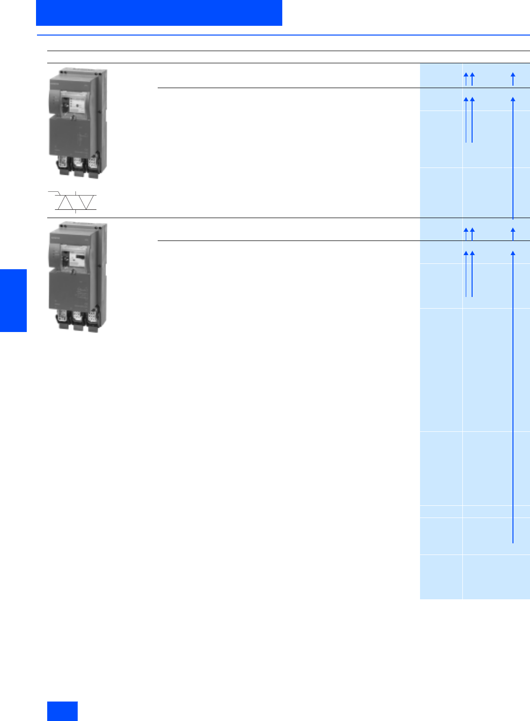
Siemens IK PI · 2004
6/110
AS-Interface Slaves
AS-Interface compact starters IP65 (400 V AC)
AS-Interface motor starters and IP65/67 load feeders
6
■
Selection and Ordering data
Design
Order No.
EDS compact starter
Electronic direct on-line starter with two spare digital inputs
3RK1 322-
@@ S12-0AA @
ERS compact starter
Electronic reversing starter with two spare digital inputs
3RK1 322-
@@ S12-1AA @
Three-phase motor
4-pole at 400 V AC standard output P Setting range
of the overcurrent release
kW A
0.18 to 0.8 0.6 to 2.18 0 A
0.75 to 2.2 2.0 to 5.95 0 B
DS compact starter
Electromechanical direct on-line starter with two spare digital inputs
3RK1 322-
@@ S02-0AA @
RS compact starter
Electromechanical reversing starter with two spare digital inputs
3RK1 322-
@@ S02-1AA @
Three-phase motor
4-pole at 400 V AC standard output P Setting range
of the overcurrent release
kW A
< 0.06 0.14 to 0.20 0 B
0.06 0.18 to 0.25 0 C
0.09 0.22 to 0.32 0 D
0.10 0.28 to 0.40 0 E
0.12 0.35 to 0.50 0 F
0.18 0.45 to 0.63 0 G
0.21 0.55 to 0.80 0 H
0.25 0.70 to 1.0 0 J
0.37 0.9 to 1.25 0 K
0.55 1.1 to 1.6 1 A
0.75 1.4 to. 2.0 1 B
0.90 1.8 to 2.5 1 C
1.1 2.2 to 3.2 1 D
1.5 2.8 to 4.0 1 E
1.9 3.5 to 5.0 1 F
2.2 4.5 to 6.3 1 G
3.0 5.5 to 8.0 1 H
4.0 7.0 to 10 1 J
5.5 9.0 to 12 1 K
Additional price
Standard version 0
Version with 24 V DC / 3 A brake contactfor externally-fed brakes 1
Version with brake contact for 400 V AC/0.5 A infeed for brake rectifier 3
Version with brake contact for DC-side switching of the bakes
with 500 V DC/0.2 A 4
N S A 0 0 0 9 8
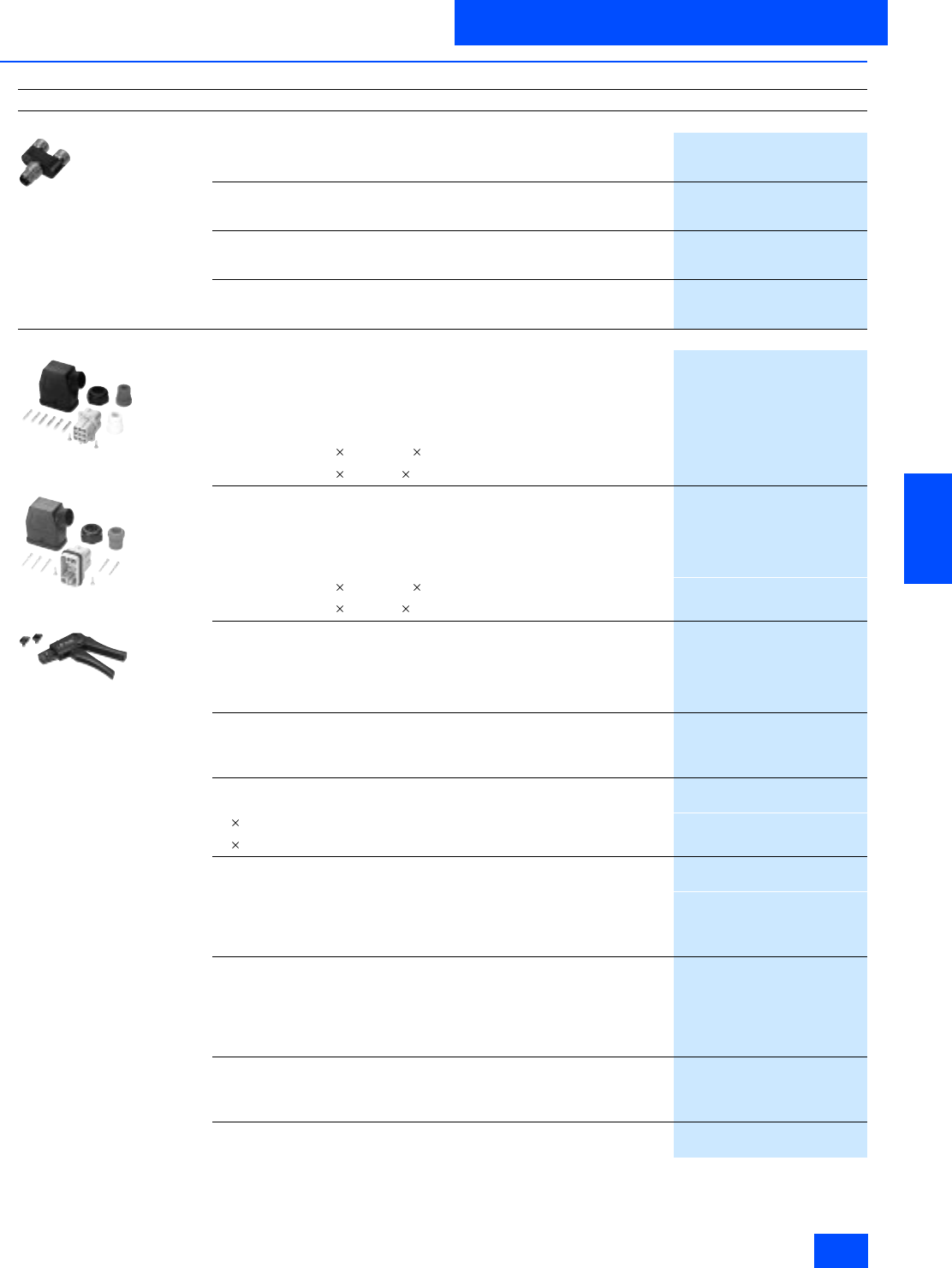
Siemens IK PI · 2004 6/111
AS-Interface Slaves
AS-Interface motor starters and IP65/67 load feeders
AS-Interface compact starters IP65 (400 V AC)
6
■
Selection and Ordering data (continued)
Design
Order No.
Accessories for 24 V DC, M 12 connectors
6ES7 194-1KA01-0XA0
M12 coupler plug
For connecting actuators or sensors
5-pole
3RX1 667
M12 angular coupler plug
For connecting actuators or sensors
5-pole
3RX1 668
Y-shaped coupler plug, M12
For connecting two sebsors by means of individual cables
5-pole
6ES7 194-1KA01-0XA0
M12 sealing cap
For sealing unused input and output sockets
(one packing contains ten sealing caps)
3RX9 802-0AA00
Accessories for AS-Interface compact starter (Han Q 8/0)
3RK1 902-0CA00
3RK1 902-0CC00
3RK1 902-0AH00
Connector set for power infeed, 9-pole
Comprising
1 connector housing with Pg 16 cable gland
Female insert, 9-pole
Female contacts
• Suitable for cable 4 2.5 mm2, 6 2.5 mm2
3RK1 902-0CA00
• Suitable for cable 4 4 mm2, 6 4 mm2
3RK1 902-0CB00
Connector set for power loop-through connection, 9-pole
Comprising
1 connector housing with Pg 16 cable gland
1 male insert, 9-pole
6 male contacts
• Suitable for cable 4 2.5 mm2, 6 2.5 mm2
3RK1 902-0CC00
• Suitable for cable 4 4 mm2, 6 4 mm2
3RK1 902-0CD00
Connector set for motor connection, 1.5 mm2, 9-pole
Comprising
1 connector housing with Pg 16 cable gland
1 male insert, 9-pole
8 male contacts 1.5 mm2
3RK1 902-0CE00
Blank plug for 9-pole power socket (-X3)
• One set contains one unit
3RK1 902-0CK00
• One set contains ten units
3RK1 902-0CJ00
Power connection cable
9-pole
•6 4 mm2, 0.12 m long
3RK1 902-0CH00
•4 4 mm2, 0.12 m long
3RK1 902-0CG00
Motor connection cable, 4 x 1.5 mm2
With power connector, 9-pole
• Length: 3 m
3RK1 902-0CM00
• Length: 5 m
3RK1 902-0CP00
• Length: 10 m
3RK1 902-0CQ00
Motor connection cable, 6 x 1.5 mm2
With power connector, 9-pole
• Length: 3 m
3RK1 902-0CN00
• Length: 5 m
3RK1 902-0CR00
• Length: 10 m
3RK1 902-0CS00
Crimping tool
• For male and female contacts 1.5 to 2.5 mm2
3RK1 902-0AH00
• For male and female contacts 1.5 to 4 mm2
3RK1 902-0CT00
Disassembling tool
for disassembling male and female contacts in 9-pole inserts
3RK1 902-0AJ00
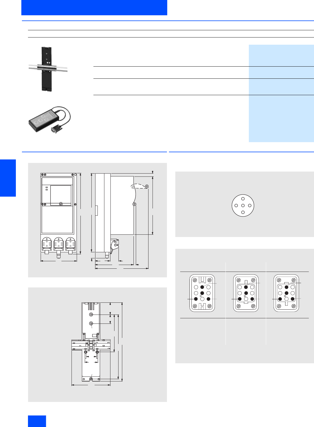
Siemens IK PI · 2004
6/112
AS-Interface Slaves
AS-Interface compact starters IP65 (400 V AC)
AS-Interface motor starters and IP65/67 load feeders
6
■
Selection and Ordering data (continued)
■
Dimensional drawings
3RK1 322-..S.-.AA.
3RK1 902-0AP00
■
Schematics
Connector pin assignment digital inputs (Y assignment)
Connector pin assignment power connector
Design
Order No.
Miscellaneous accessories
3RK1 902-0AP00
3RK1 902-0AM00
Manual for AS-Interface compact starters
• German, English
3RK1 702-2GB10-2AA0
• French, Italian
3RK1 702-2HB10-2AA0
Mounting plate for compact starters
To receive the shaped cable for AS-Interface and auxiliary power
3RK1 902-0AP00
Seal set for mounting plate
For sealing the housing at the end of a spur line
(1 set = 5 straight seals, 5 shaped seals)
3RK1 902-0AR00
Hand-held terminal for start-up
with 0.5 m connecting cable and plug
3RK1 902-0AM00
N S A 0 _ 0 0 1 0 1 b
2 7 0
1 2 0
1 9 7 9
2 6 5
5 4
1 2 6
2 5
9
1 9 0
2 5
N S A 0 _ 0 0 1 0 2
1 0 7
4 0 , 5
2 6 5
1 2 0
3 4
2 1 4
3 3
3 9
Æ 4 , 8
Æ 5
N S A 0 _ 0 0 1 0 0
P i n 1 : S u p p l y L +
P i n 2 : S i g n a l i n p u t
P i n 3 : S u p p l y L
P i n 4 : S i g n a l i n p u t
P i n 5 : P E
6
1
4
8
3
5
2
7
L 2
L 3
L 1
- X 2
6
1
4
8
3
5
2
7
L 2
L 3 L 1
- X 1
8
3
5
6
1
4
2
7
L 2
L 3
L 1
- X 3
N S A 0 _ 0 0 3 4 9
P i n 1 :
P i n 2 :
P i n 3 :
P i n 4 :
P i n 5 :
P i n 6 :
P i n 7 :
P i n 8 :
C e n t e r :
n o t a s s i g n e d
P h a s e L 2
s p a r e
G N D f o r b r a k e o p t i o n a l
+ D C 2 4 V f o r b r a k e o p t i o n a l
P h a s e L 1
n o t a s s i g n e d
P h a s e L 3
P E
n o t a s s i g n e d
P h a s e L 2
s p a r e
+ D C 2 4 V f o r b r a k e
G N D f o r b r a k e
P h a s e L 3
n o t a s s i g n e d
P i n 1 : P h a s e L 1
P E
1 ) O n l y f o r A S - I n t e r f a c e c o m p a c t s t a r t e r s w i t h D C 2 4 V b r a k e c o n t a c t ( 3 R K 1 3 2 2 - . . S . . - . A A 1 ) .
P i n 1 :
P i n 2 :
P i n 3 :
P i n 4 :
P i n 5 :
P i n 6 :
P i n 7 :
P i n 8 :
C e n t e r :
1 )
1 )
1 )
1 )
X 2 :
X 1 : P o w e r i n f e e d
( p l u g o f t h e s t a r t e r )
L o a d f e e d e r
( s o c k e t o f t h e s t a r t e r )
X 3 : P o w e r l o o p - t h r o u g h c o n n e c t i o n
( s o c k e t o f t h e s t a r t e r )
P i n 1 :
P i n 2 :
P i n 3 :
P i n 4 :
P i n 5 :
P i n 6 :
P i n 7 :
P i n 8 :
C e n t e r :
P h a s e L 1
n o t a s s i g n e d
P h a s e L 3
B r a k e o u t p u t
B r a k e i n p u t
n o t a s s i g n e d
P h a s e L 2
n o t a s s i g n e d
P E
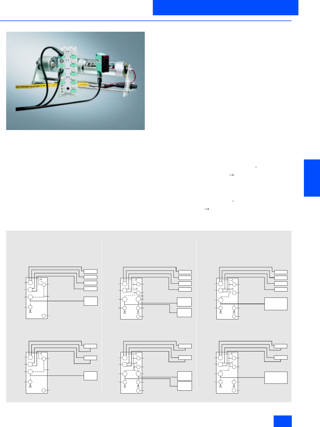
Siemens IK PI · 2004 6/113
AS-Interface Slaves
AS-Interface motor starters and IP65/67 load feeders
AS-Interface motor starters IP67 (24 V DC)
6
■
Overview
Connection of a drive roller with integrated DC motor to an AS-Interface
DC 24 V motor starter
With the K60 AS-Interface 24 V DC motor starters for the low-end
performance range up to 70 W, it is now possible to connect
24 V DC motors and the associated sensors directly to the AS-
Interface quickly and easily.
Three different versions are available:
• Single direct on-line starter (without brake and reversible
quick-stop function)
• Double direct on-line starter (with brake and reversible quick-
stop function)
• Reversing starter (with brake and reversible quick-stop func-
tion)
DC motors are connected to the module via M12 plug-in con-
nectors. The sensors and the module electronics can be sup-
plied from the yellow AS-Interface cable. An auxiliary voltage
(DC 24 V) is only required for supplying the outputs, which can
be provided via the black AS-Interface cable.
Quick stop function
All AS-Interface 24 V DC motor starters feature a quick-stop
function which can be switched on and off as required via a
switch integrated into the module. The quick-stop function al-
lows a connected motor to be shut down immediately via an ap-
plied sensor signal (high). The switch for the quick-stop function
is located alongside the input sockets and is protected by an
M12 covering cap.
Brake
The double direct starter and reversing starter versions feature
an integrated permanently set brake function. As soon as the
output signal is set to "0", the motor is braked.
Start-up via integrated buttons
Buttons integrated into the module (below the output sockets)
can be used to set the motor used. The buttons are protected by
an M12 covering cap.
Note concerning double and reversing starters: If an input with
the Quick stop function receives a "High" signal, the correspond-
ing output (e.g. Quick stop input 1 output 1) is switched off
within the device (the motor is braked). The manual key function
(Key 1/2) for local operation is only permitted to be used during
"CPU Stop" in the higher-level PLC.
Note for single direct on-line starters: If an input with the Quick
stop function receives a "High" signal, the corresponding output
(e.g. Quick stop input 1 output 1) is switched off within the de-
vice (the motor coasts down without braking). The manual key
function (Key 1) for local operation is only permitted to be used
during "CPU Stop" in the higher-level PLC.
Applications
4 2
2
4
4 2
2
4
4 2
2
4
4 2
2
4
4 2
2
4
4 2
2
4
N S A 0 _ 0 0 3 4 8
I n p u t 1
I n p u t 2
O u t p u t
B u t t o n
( m a n u a l
operation)
Q u i c k - s t o p f o r
o u t p u t
o n / o f f
A d d r e s s
S e n s o r 1
S e n s o r 2
S e n s o r 3
S e n s o r 4
M o t o r
S e n s o r s i g n a l
S e n s o r s i g n a l
S e n s o r s i g n a l
S e n s o r s i g n a l
o f f
o n
B r a k e
( w i t h c o a s t i n g )
I n p u t 1
I n p u t 2
O u t p u t
B u t t o n
(m anual
operation)
Q u i c k - s t o p f o r
o u t p u t
o n / o f f
A d d r e s s
S e n s o r 1
S e n s o r 2
P o l l u t i o n s i g n a l
S e n s o r s i g n a l
S e n s o r s i g n a l
P o l l u t i o n s i g n a l
M o t o r
B r a k e
( w i t h c o a s t i n g )
o f f
o n
I n p u t 1
I n p u t 2
O u t p u t 1
B u t t o n 1
( m a n u a l
operation)
O u t p u t 2
Q u i c k - s t o p f o r
output 2 on/off
Q u i c k - s t o p f o r
output 1 on/off
B u t t o n 2
( m a n u a l o p e r a t i o n )
A d d r e s s
S e n s o r 1
S e n s o r 2
S e n s o r 3
S e n s o r 4
S e n s o r s i g n a l
S e n s o r s i g n a l
S e n s o r s i g n a l
S e n s o r s i g n a l
o f f
o n
o f f
o n
M o t o r 2
M o t o r 1
S h o r t - c i r c u i t b r a k e
I n p u t 1
I n p u t 2
O u t p u t 1
Q u i c k - s t o p f o r
output 1 on/off
A d d r e s s
S e n s o r 1
S e n s o r 2
M o t o r 2
P o l l u t i o n s i g n a l
S e n s o r s i g n a l
S e n s o r s i g n a l
o f f
o n
o f f
o n Q u i c k - s t o p f o r
output 2 on/off
P l u g b r a k e
P o l l u t i o n s i g n a l
O u t p u t 2
( m a n u a l o p e r a t i o n )
B u t t o n 2
M o t o r 1
I n p u t 1
I n p u t 2
O u t p u t
Q u i c k - s t o p f o r
o u t p u t 1 o n / o f f
A d d r e s s
S e n s o r 1
S e n s o r 2
S e n s o r 3
S e n s o r 4
M o t o r
C l o c k w i s e r o t a t i o n
C o u n t e r - c l o c k w i s e
r o t a t i o n
S e n s o r s i g n a l
S e n s o r s i g n a l
S e n s o r s i g n a l
S e n s o r s i g n a l
o f f
o n
o f f
o n Q u i c k - s t o p f o r
o u t p u t 1 o n / o f f
P l u g b r a k e
I n p u t 1
I n p u t 2
O u t p u t
Q u i c k - s t o p f o r
output 1 on/off
A d d r e s s
S e n s o r 1
S e n s o r 2
M o t o r
C l o c k w i s e r o t a t i o n
C o u n t e r - c l o c k w i s e
r o t a t i o n
S e n s o r s i g n a l
S e n s o r s i g n a l
o f f
o n
o f f
o n Q u i c k - s t o p f o r
output 1 on/off
P l u g b r a k e
P o l l u t i o n s i g n a l
P o l l u t i o n s i g n a l
B u t t o n 1
(m anual
o p e r a t i o n f o r
c l o c k w i s e
r o t a t i o n )
B u t t o n 2
( m a n u a l o p e r a t i o n
f o r c l o c k w i s e r o t a t i o n )
B u t t o n 2
( m a n u a l o p e r a t i o n
f o r c l o c k w i s e r o t a t i o n )
B u t t o n 1
( m a n u a l
o p e r a t i o n f o r
c l o c k w i s e
r o t a t i o n )
B u t t o n 1
( m a n u a l
o p e r a t i o n )
( w i t h a d j u s t a b l e q u i c k - s t o p f u n c t i o n )
1 s t p o s s i b i l i t y : C o n n e c t i o n t o a m a x i m u m o f f o u r
s e n s o r s w i t h o u t p o l l u t i o n i n d i c a t i o n
S i n g l e d i r e c t s t a r t e r w i t h o u t b r a k e
( w i t h a d j u s t a b l e q u i c k - s t o p f u n c t i o n )
D o u b l e d i r e c t s t a r t e r w i t h b r a k e
1 s t p o s s i b i l i t y : C o n n e c t i o n t o a m a x i m u m o f f o u r
s e n s o r s w i t h o u t p o l l u t i o n i n d i c a t i o n
( w i t h a d j u s t a b l e q u i c k - s t o p f u n c t i o n )
S i n g l e r e v e r s i n g s t a r t e r w i t h b r a k e
C o n n e c t i o n t o a m a x i m u m o f f o u r
s e n s o r s w i t h o u t p o l l u t i o n i n d i c a t i o n
1 s t p o s s i b i l i t y :
2 n d p o s s i b i l i t y : C o n n e c t i o n t o a m a x i m u m o f t w o
s e n s o r s w i t h p o l l u t i o n i n d i c a t i o n
2 n d p o s s i b i l i t y : C o n n e c t i o n t o a m a x i m u m o f t w o
s e n s o r s w i t h p o l l u t i o n i n d i c a t i o n
C o n n e c t i o n t o a m a x i m u m o f t w o
s e n s o r s w i t h p o l l u t i o n i n d i c a t i o n
2 n d p o s s i b i l i t y :

Siemens IK PI · 2004
6/114
AS-Interface Slaves
AS-Interface motor starters IP67 (24 V DC)
AS-Interface motor starters and IP65/67 load feeders
6
■
Technical specifications
Single direct on-line starter Double direct on-line starter Single reversing starter
4 inputs 4 inputs 4 inputs
1 output 2 outputs 1 output
Quickstop function
3RK1 400-1NQ01-0AA4 3RK1 400-1MQ01-0AA4 3RK1 400-1MQ03-0AA4
Slave type Standard slaves
Operational voltage in accordance
with AS-Interface specification in V 26.5 to 31.5
Total current input from AS-Interface
in mA 270
Input connection PNP
Inputs
• Sensor supply via AS-Interface Short-circuit and overload proof
•Sensors 3-wire
• Voltage range in V 20 to 30
• Load rating for sensor supply
in mA 200 (Tu 40 °C) / 150 (Tu 55 °C)
• Switching level High in V 10
• Switching level Low in V 5
• Socket assignment PIN 1 = Sensor supply L+
PIN 2 = Data input
PIN 3 = Sensor supply L-
PIN 4 = Data input/Quickstop
PIN 5 = Earth connection
• External voltage supply DC 24 V Via black AS-Interface flat cable
• Max. start-up ramp time for DC
motor in ms 80
• Max. motor start-up current
(internally limited) in A 4.5
Outputs
• Type of output Electronics
• Nominal load rating per output in A 3 (Tu 55 °C)
-1 x 3 (Tu 55 °C)
2 x 2 (Tu 55 °C) 2.5 (Tu 55 °C)
-
• Max. total current in A - 4 -
• Voltage drop (without incoming
line) in V 0.6 1.2
• Short-circuit protection Built-in
• Inductive interference protection
(free-wheeling diode) Built-in
• Watchdog Built-in
I/O configuration 7
ID code F
Assignment of data bits
• Socket 1 PIN4 = IN1 (D0 / Quickstop1)
PIN2 = IN2 (D1)
• Socket 2 PIN4 = IN3 (D2)
PIN2 = IN4 (D3) PIN4 = IN3 (D2 / Quickstop2)
PIN2 = IN4 (D3)
• Socket 3 PIN4 = OUT1(D0) PIN4 = OUT1(D0) PIN2,4 = OUT1 (D0, D1)
• Socket 4 -PIN4 = OUT2(D1) -
AS-Interface certificate Yes
Approvals UL, CSA
Degree of protection IP67
Earth connection Yes
Ambient temperature in °C -25 to +55
Storage temperature in °C -40 to +85
Number of I/O sockets 3 3
Note Max. switching frequency when
activating, e. g. a 10 W DC motor
(UAux = 28.8 V/duty cycle = 50 %):
•Tumax/°C: 55
• Max. switching frequency/h: 1500
Max. switching frequency when
activating, e. g. a 10 W DC motor
(UAux = 28.8 V/duty cycle = 50 %):
•Tumax/°C: 55
• Max. switching frequency/h: 1500
Max. switching frequency when
activating, e. g. a 10 W DC motor
(UAux = 28.8 V/duty cycle = 50 %):
•Tumax/°C: 55
• Max. switching frequency/h: 1000
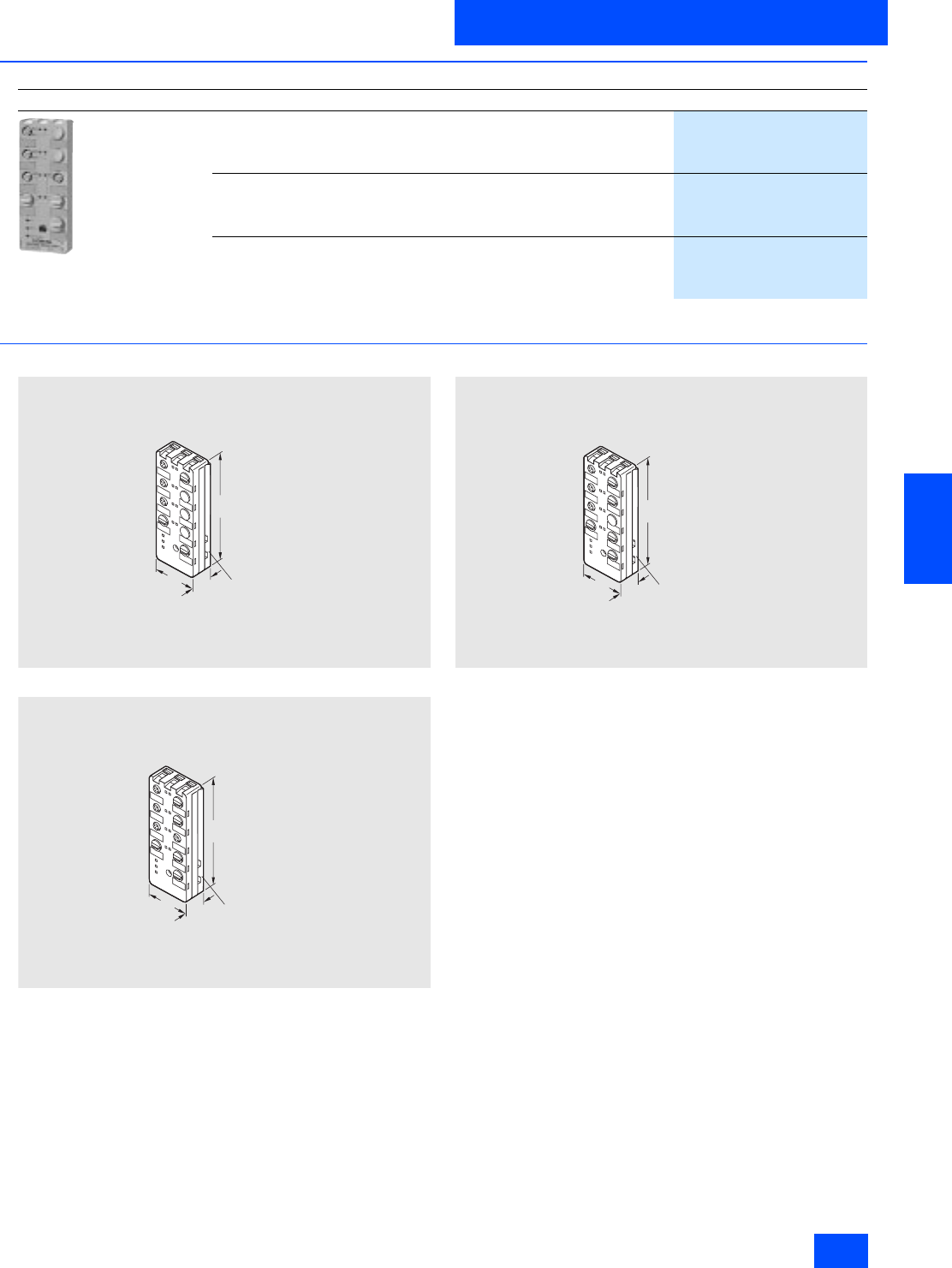
Siemens IK PI · 2004 6/115
AS-Interface Slaves
AS-Interface motor starters and IP65/67 load feeders
AS-Interface motor starters IP67 (24 V DC)
6
■
Selection and Ordering data
1) Modules supplied without mounting plate.
■
Dimensional drawings
3RK1 400-1NQ01-0AA4
3RK1 400-1MQ01-0AA4
3RK1 400-1MQ03-0AA4
Design Order No.
3RK1 400-1MQ01-0AA4
Single direct on-line starter 1)
4 inputs
1 output
Quickstop function
3RK1 400-1NQ01-0AA4
Dual direct on-line starter 1)
4 inputs
2 outputs
Quickstop function
3RK1 400-1MQ01-0AA4
Single reversing starter 1)
4 inputs
1 output
Quickstop function
3RK1 400-1MQ03-0AA4
29
NSA0_00113a
152
60
3RK1901-0CA00
mounting plate
29
NSA0_00114a
152
60
3RK1901-0CA00
mounting plate
29
NSA0_00115a
152
60
3RK1901-0CA00
mounting plate
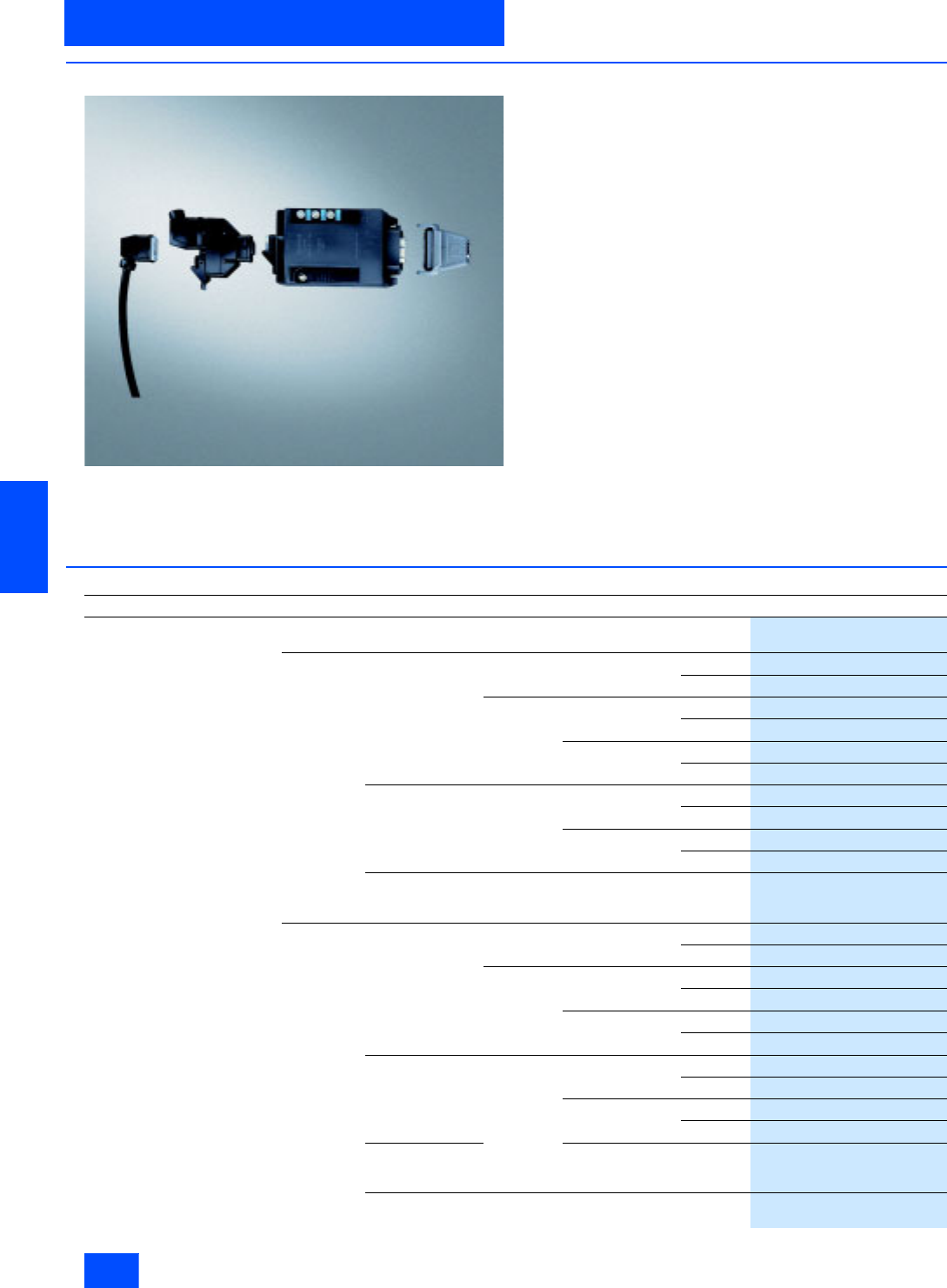
Siemens IK PI · 2004
6/116
AS-Interface Slaves
ECOFAST motor and soft starter
AS-Interface motor starters and IP65/67 load feeders
6
■
Overview
Distributed motor starters are used for switching and protecting
loads locally. Versions with graded functional scope and with
different installation possibilities ensure that both the functional
requirements of the process and the constructional boundary
conditions of the machine or installation are taken into account.
Distributed motor starters are available for PROFIBUS DP and
AS-Interface.
The starters can be installed in the vicinity of the motor or
mounted onto the motor.
The following are available
• Single units for geographically distributed motors and
• Isolated solutions (ET 200X) for drives installed close together.
The functionality in the ECOFAST system ranges from direct on-
line starters, to reversing starters and soft starters through to
frequency converters (ET 200X).
Brake contacts are available as an option for the starters.
Two resp. four integrated digital contacts enable sensors to be
scanned locally.
All starters are equipped throughout with standardized inter-
faces for data and power in accordance with the ECOFAST
specification (DESINA compatible):
• HanBrid for PROFIBUS DP resp. insulation displacement
method for AS-Interface
• Han Q8 for the power supply
• Han 10e for motor connection
The starters can be connected using T pieces for data and
power to prevent interruption.
■
Selection and Ordering data
Design Order No.
Fieldbus
interface Switching
function Motor
protection Adjustment/
performance range Brake
output
PROFIBUS
DP Mechanical Thermistor 0.3 to 9 A/4 kW No
3RK1 303-2AS51-1AA0
400 V AC
3RK1 303-2AS51-1AA3
Thermal
motor model 0.3 to 3 A/1.1 kW No
3RK1 303-5BS41-1AA0
400 V AC
3RK1 303-5BS41-1AA3
2.4 to 9 A/4 kW No
3RK1 303-5CS41-1AA0
400 V AC
3RK1 303-5CS41-1AA3
Electronic, soft Full motor
protection 0.3 to 3 A/1.1 kW No
3RK1 303-6BS71-1AA0
400 V AC
3RK1 303-6BS71-1AA3
2.4 to 12 A/5.5 kW No
3RK1 303-6DS71-1AA0
400 V AC
3RK1 303-6DS71-1AA3
electronic soft,
several speeds,
R255
0.6 to 4 A/1.5 kW 400 V AC
3RK1 303-6ES81-3AA3
AS-Interface Mechanical Thermistor 0.3 to 9 A/4 kW No
3RK1 323-2AS51-1AA0
400 V AC
3RK1 323-2AS51-1AA3
Thermal
motor model 0.3 to 3 A/1.1 kW No
3RK1 323-5BS41-1AA0
400 V AC
3RK1 323-5BS41-1AA3
2.4 to 9 A/4 kW No
3RK1 323-5CS41-1AA0
400 V AC
3RK1 323-5CS41-1AA3
Electronic, soft Full motor
protection 0.3 to 3 A/1.1 kW No
3RK1 323-6BS71-1AA0
400 V AC
3RK1 323-6BS71-1AA3
2.4 to 12 A/5.5 kW No
3RK1 323-6DS71-1AA0
400 V AC
3RK1 323-6DS71-1AA3
electronic soft,
several speeds,
R255
0.6 to 4 A/1.5 kW 400 V AC
3RK1 323-6ES81-3AA3
Micro Starter
mechanical Thermistor 0.3 to 9 A/4 kW No see Catalog M11
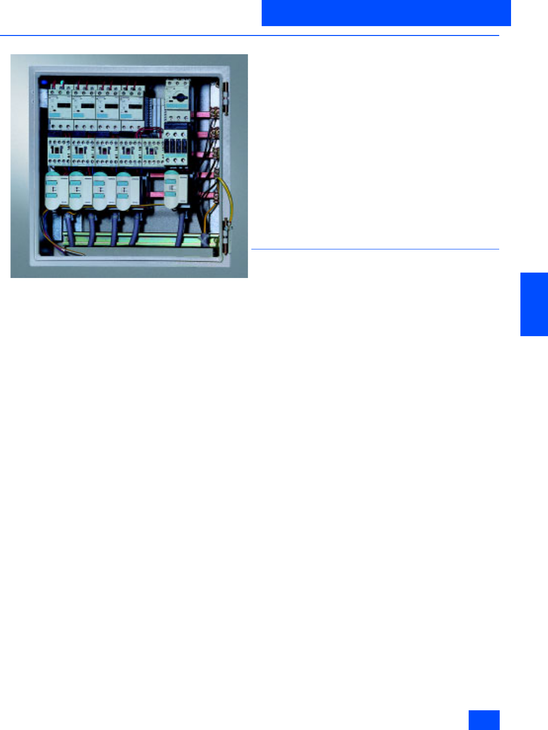
Siemens IK PI · 2004 6/117
AS-Interface Slaves
AS-Interface motor starters and IP20 load feeders
AS-Interface load feeder modules IP20
6
■
Overview
AS-Interface load feeder module
The AS-Interface load feeder module serves as an additional in-
put/output module for the conventional busbar and standard
mounting rail adapters. It enables the control circuit of a load
feeder to be completely prewired. The series has been opti-
mized for use in conjunction with the SIRIUS load feeders (sizes
S00 and S0). The connection to the higher-level automation sys-
tem is made via the interface between the AS-Interface and the
load feeder module. An unshielded, standard litz wire can be
used as the data line and for the 24 V DC load power supply. The
connection to the AS-Interface load feeder module is made by
means of two insulation-piercing connectors.
Four different AS-Interface load feeder modules are available:
The versions differ in the number of inputs and outputs, as well
as in the type of outputs. The units with electronic outputs are de-
signed for 24 V DC, whereas units with relay outputs are de-
signed for voltages of up to 230 V AC. They enable direct-on-line
and reversing starters, double direct-on-line starters and starter
combinations to be wired for pole-changing. The status signals
from the circuit-breakers and the contactor(s) can be interro-
gated separately at the inputs. The outputs are used to control
the contactor coils directly.
Since the outputs already have overvoltage protection inte-
grated, additional measures are not required for the contactors.
The outputs are fed by a separate auxiliary power supply, which
facilitates a selective emergency stop concept. The inputs are
supplied via the AS-Interface data line. The inputs and outputs
must be wired via integrated Cage Clamp terminals which are
connected to a common potential.
3RA5 fuseless load feeder with connection to an
AS-Interface
The 3RA5 fuseless load feeder, consisting of AS-Interface load
feeder module, circuit-breaker and contactor, together with all
necessary connectors (AS-Interface, auxiliary power and 5-pole
power connector), is supplied completely assembled, wired and
tested. This saves the user valuable time required for installation,
wiring and servicing.
Also available are direct online starters and reversing starters
with SIRIUS switchgear of sizes S00 up to 10 A and size S0 - de-
termined by the power connector - for up to 16 A. The complete
feeder units are available with AS-Interface load feeder modules
with electronic outputs for an auxiliary voltage of DC 24 V.
Load feeder units of this kind are used, for instance, to control
standard three-phase motors. The load feeders can be installed
in central switchgear cubicles or in distributed, onsite switch-
gear boxes. They are particularly suitable for machines and
plants where the degree of automation is high and special im-
portance is attached to availability.
■
Design
The AS-Interface load feeder module is snapped onto a match-
ing support for switching devices. A 5-pole power supply con-
nector can optionally be fitted between the load feeder module
and the support.
If this connector is used, all the load feeder connections are of
the plug-in type. The unit can thus be replaced very easily if nec-
essary. If this connector is used, the current is limited to 16A.
Several versions of the controlgear support are available; the
choice depends on the width of the controlgear combination
(45 mm or 54 mm) and on the busbar system which is used (bus-
bar center-line spacing 40 mm or 60 mm). Depending on the
variant, the N and/or PE conductors or neither conductor is
brought out as well. The connecting cables of the loads can thus
be prefabricated beforehand and laid directly to the AS-Inter-
face load feeder module via the optional power supply connec-
tor, then installed at this module without any additional wiring.
The loads, for example a three-phase standard motor, can be
exchanged easily in this way.
Each AS-Interface bus station must be assigned a unique ad-
dress at the commissioning stage at the latest. In the case of the
AS-Interface load feeder module, this can be achieved either via
the master by plugging in the connectors which are connected
to the data line one at a time (only one station in the network is
allowed to respond to the default address 0), or by allocating in-
dividual addresses by means of the addressing device and line.
This addressing method can still be used even if the compact
starter is fully wired, as the module is disconnected from the
AS-Interface network as soon as the addressing connector is
inserted.
The addressing socket is located underneath the item code
plate on the front of the load feeder module. The LEDs for diag-
nosing the AS-Interface load feeder module are also situated
there. The following states are displayed:
• 24 V DC auxiliary voltage present or output/outputs set
(230 V AC version)
• AS-Interface communication o.k.
• AS-Interface communication fault
• Station address = 0 (module not addressed)

Siemens IK PI · 2004
6/118
AS-Interface Slaves
AS-Interface load feeder modules IP20
AS-Interface motor starters and IP20 load feeders
6
■
Technical specifications
The technical specifications for the load feeders is the same as that specified for the individual devices.
The high short-circuit strength of Iq = 50 kA also applies.
Load feeders modules IP20
2I/1O 4I/2O 2I/1OR 3I/2OR
3RK1 400-1KG01-0AA1 3RK1 400-1MG01-0AA1 3RK1 402-3KG02-0AA1 3RK1 402-3LG02-0AA1
I/O configuration (hex) 3 7 3 7
ID code (hex) F F F F
Supply voltage for electronics
and inputs in V
(checkbacks from the auxiliary
contacts of the controlgear)
via AS-Interface data cable
26.5 to 31.6 (in accordance with AS-Interface specification)
Power consumption of AS-Interface
in mA 8 to 12
Temperature range
• Operating temperature Tu in °C 0 to +55
• Storage temperature in °C -40 to +85
Degree of protection IP20
Inputs
Polarity reversal protection Built-in
Max. input current in mA 6
Max. permissible cable length
between IN + and an input in m 0.4
Outputs
External supply voltage for outputs
in V
(triggering of the contactor coils)
via auxiliary power
24 DC Max. 230 AC
Current carrying capacity Ie in A 0.5 (DC-13/DC-14) 3 (AC-15); 0.1 (DC-13 at 220 V)
Summation current (thermal) Ith in A 2 3
Polarity reversal protection Built-in Not required
Short-circuit protection Built-in No
Inductive interference protection
(free-wheeling diode) Built-in Not required
Watchdog
(shutdown of outputs in case
of AS-Interface fault)
Built-in
Diagnostics
Via LED at the housing Auxiliary voltage applied
AS-Interface communication OK
AS-Interface communication faulty
Station address = 0 (module not addressed)
Output activated
AS-Interface communication OK
AS-Interface communication faulty
Station address = 0 (module not addressed)
Conductor cross-sections
Plug connector for AS-Interface and
auxiliary power in mm20.5 to 0.75 (flexible)
Cage Clamp for I/O wiring in mm20.8 to 2.5 (flexible, without end sleeve)
Power connector, 5-pole in mm20.5 to 2.5
AWG 28 to 12
PE/N conductor wiring on carrier
in mm22.5 flexible
AWG 13
Addressing After the 15th addressing, the module keeps the last address
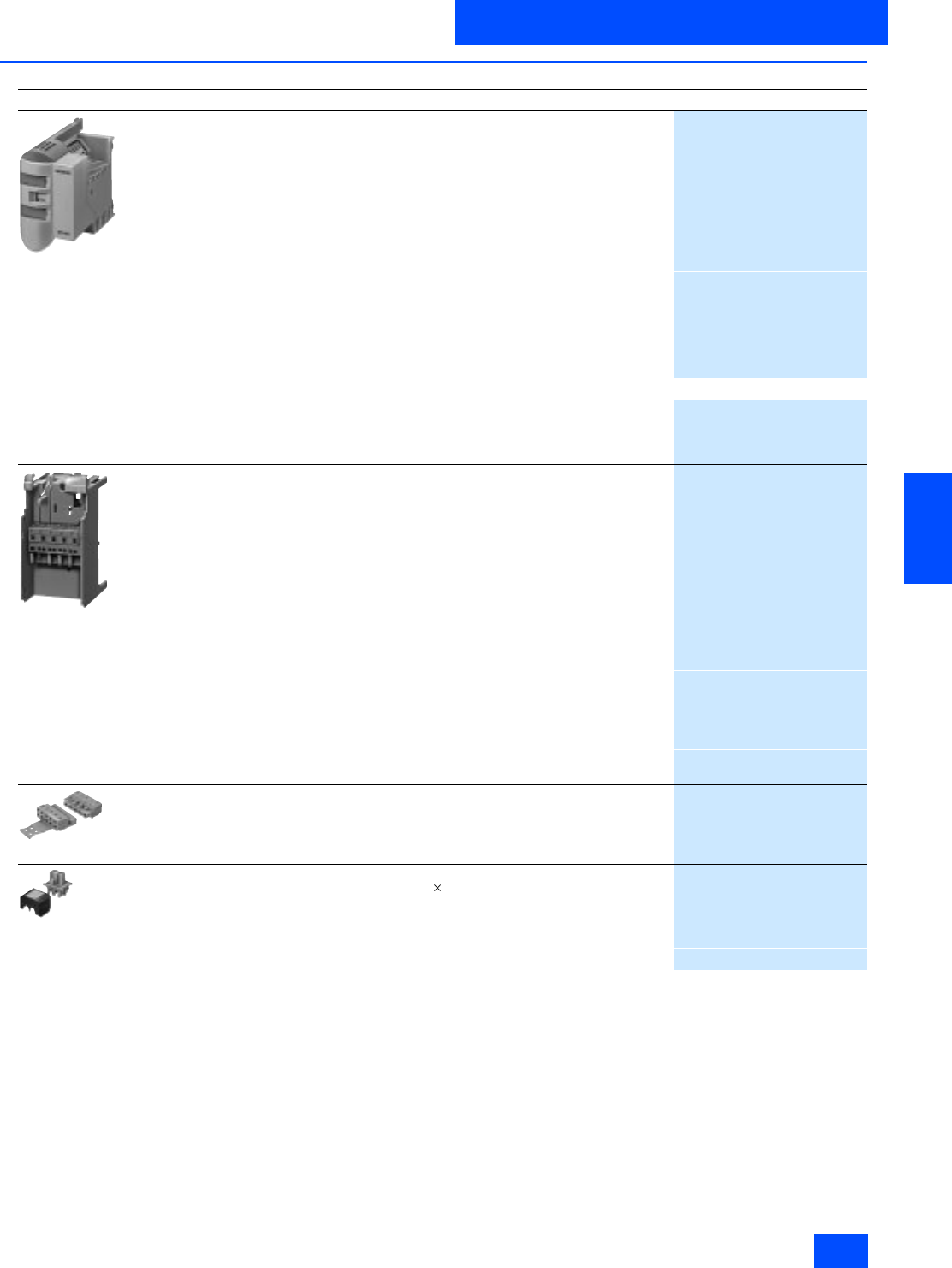
Siemens IK PI · 2004 6/119
AS-Interface Slaves
AS-Interface motor starters and IP20 load feeders
AS-Interface load feeder modules IP20
6
■
Selection and Ordering data
1) Complete feeders with AS-Interface load feeder module:
See Catalog LV 10 Section "Load Feeders and Soft Starters"
2) Without connectors for data and auxiliary power (yellow and black).
3) With one connector each for data and auxiliary power (yellow and red).
4) Busbar accessories: See Catalog LV 10 Section "Load Feeders and Soft Starters"
and "Distribution Systems, Busbar Systems and Switchgear"
Design
Order No.
3RK1 400-1KG01-0AA1
3RK1 400-1MG01-0AA1
AS-Interface load feeder module 1 )
For mounting onto standard rails
For contactors sizes S00 and S0
For mounting on 40 mm or 60 mm busbar systems and SIRIUS standard rail
adapters, the matching carrier is required (see Accessories)
The AS-Interface connectors for the data and auxiliary power cable (yellow and
black) must be ordered separately (see Accessories)
Type Supply in V
2 inputs /
1 output 24 DC 2)
3RK1 400-1KG01-0AA1
4 inputs/
2 outputs
3RK1 400-1MG01-0AA1
2 inputs /
1 relay output 120/230 AC 3)
3RK1 402-3KG02-0AA1
3 inputs /
2 relay outputs
3RK1 402-3LG02-0AA1
Accessories 4)
Manual for AS-Interface load feeder module
• German, English
3RK1 701-2GB00-0AA0
• Italian, French
3RK1 701-2HB00-0AA0
Carrier with mounted power
connector coupling
Carrier for AS-Interface load feeder module
• With PE and N conductor connection,
for mounting on busbar adapter with 40 mm rail center-line spacing
Power connector set 3RK1 901-0EA00 is necessary
-45 mm
3RK1 901-3AA00
-54 mm
3RK1 901-3BA00
• With PE and N conductor connection,
for mounting on busbar adapter with 60 mm rail center-line spacing
Power connector set 3RK1 901-0EA00 is necessary
-45 mm
3RK1 901-3CA00
-54 mm
3RK1 901-3DA00
• Without PE and N conductor connection,
for mounting on busbar adapter with 40 mm or 60 mm rail center-line spacing
-45 mm
3RK1 901-3EA00
-54 mm
3RK1 901-3FA00
• for mounting on SIRIUS adapter 3RA19 22-1A for rail mounting
45 mm
3RK1 901-3GA00
3RK1 901-0EA00
Power connector set
5-pole, 2.5 mm2
(one set contains five connectors and five couplings)
3RK1 901-0EA00
3RK1 901-0NA00
3RK1 901-0PA00
AS-Interface connectors for data and auxiliary power cable
With insulation-piercing terminals for 2 (0.5 to 0.75 mm2)
standard stranded conductors
(one packing contains five connectors)
• Yellow
3RK1 901-0NA00
•Black
3RK1 901-0PA00
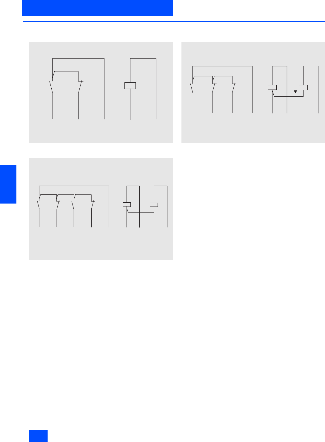
Siemens IK PI · 2004
6/120
AS-Interface Slaves
AS-Interface load feeder modules IP20
AS-Interface motor starters and IP20 load feeders
6
■
Schematics
Typical control circuits
AS-Interface load feeder module with 2 inputs and 1 output as
direct on-line starter
AS-Interface load feeder module with 4 inputs and 2 outputs as
dual direct on-line starter
AS-Interface load feeder module with 4 inputs and 2 outputs or 3 inputs
and 2 outputs as reversing starter
When using SIRIUS contactors, we recommend that the posi-
tively-driven auxiliary NC contacts are used for feedback of the
switching status.
I N 1
N S A 0 0 0 9 7
I N 2 M / N
- X 3 . 1 - X 3 . 2 - X 3 . 3 - X 4 . 1 - X 4 . 2
I N + O U T 1
- Q 1 - K 1 - K 1
N S A 0 0 0 9 5
I N 4 M / N
- X 3 . 3 - X 3 . 4 - X 3 . 5 - X 3 . 6 - X 3 . 7
- X 3 . 2 - X 3 . 8
I N 3
I N 1 I N 2
- X 3 . 1
I N + O U T 1 O U T 2
- Q 1 - K 1 - Q 2 - K 2 - K 1 - K 2
N S A 0 0 0 9 6
I N 3 M / N
- X 3 . 2 - X 3 . 3 - X 3 . 5 - X 3 . 6 - X 3 . 7
I N 1 I N 2
- X 3 . 1 - X 3 . 8
I N + O U T 1 O U T 2
- Q 1 - K 1 - K 2 - K 1 - K 2
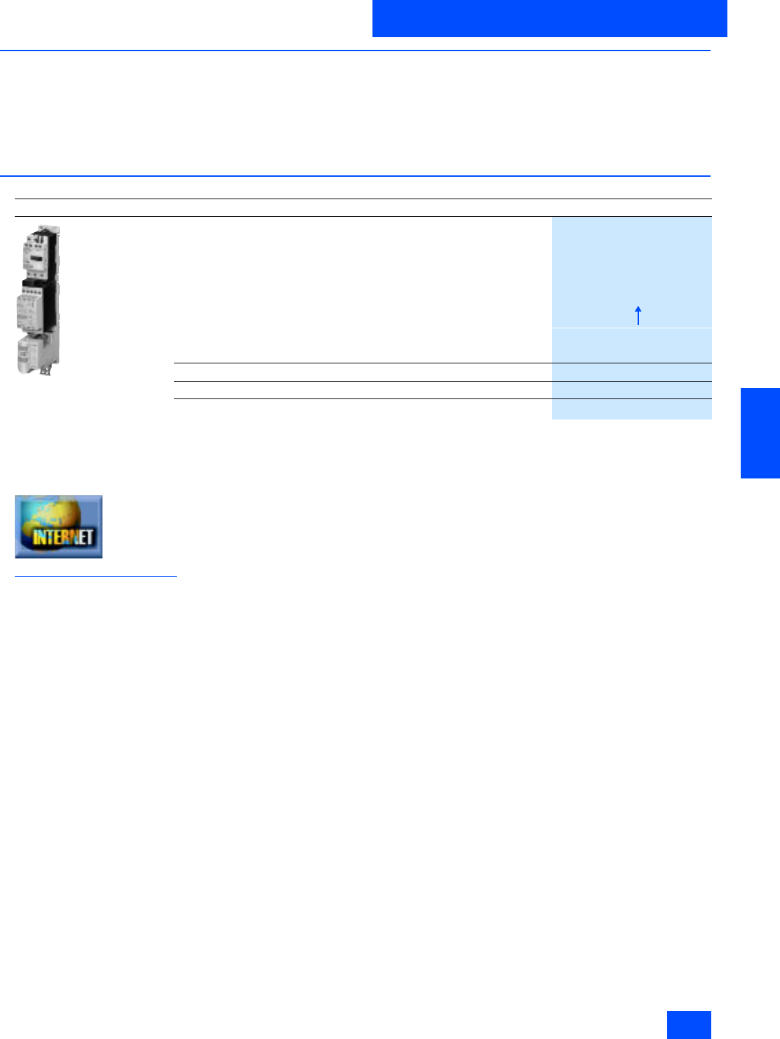
Siemens IK PI · 2004 6/121
AS-Interface Slaves
AS-Interface motor starters and IP20 load feeders
SIRIUS soft starters
6
■
Overview
The SIRIUS electronic soft starters are suitable for controlled soft
starting and running down of three-phase asynchronous motors.
Reduction of the starting torque not only protects the motor, but
also increases the availability of the installation.
With just a few actions and accessories, motor feeders can be
fitted with these soft starters for communications capability.
The advantages of a soft starter are:
• Reduction of mechanical loading throughout the drive
• Reduction of the loading on the power supply system
■
Selection and Ordering data
1) For mounting the AS-Interface load feeder module on the standard
rail adaptor, a carrier, plug connector and power connector set are
also required.
Additional information is available in the Internet under:
http://www.siemens.de/sanftstarter
Design
Order No.
SIRIUS Soft Starter
with AS-Interface load feeder
module 1)
SIRIUS Soft Starter
Rated operating voltage for unit Ue at 400 V
(ambient temperature 40°C)
Rated power of motors
3 kW
3RW3 014-1CB
@4
4 kW
3RW3 016-1CB
@4
Rated control supply voltage
UC = 24 V 0
UC = 110 to 230 V 1
AS-Interface load feeder module
• 2 inputs / 1 output / 24 V DC
3RK1 400-1KG01-0AA1
• 2 inputs / 1 relay output / 120/230 V AC
3RK1 402-3KG02-0AA1
Siemens IK PI · 2004
6/122
AS-Interface Slaves
AS-Interface F-Adapter for EMERGENCY STOP
command devices
SIGNUM pushbuttons and indicator lights
6
■
Overview
The AS-Interface F adapter is used for connecting the
EMERGENCY STOP devices of the SIGNUM 3SB3 series to
AS-Interface.
■
Design
The F adapter has a safe AS-Interface slave and is snapped
onto the back of the EMERGENCY STOP device that is not in-
cluded in the scope of supply.
Connection is via the AS-Interface shaped cable using the insu-
lation piercing method.
Addressing is via the AS-Interface connections or via the built-in
addressing socket.
■
Selection and Ordering data
1) EMERGENCY STOP actuator is not included in the scope of supply.
For further details on the EMERGENCY-STOP actuator, see the
Section Pushbutton Units and Indicator Lights in Catalog NS K,
10/2001 Edition or Catalog LV 10, 2004 Edition.
Design
Order No.
AS-Interface F adaptor, for EMERGENCY STOP actuator SIGNUM 3SB3 1)
Front panel mounting
3SF5 402-1AA01
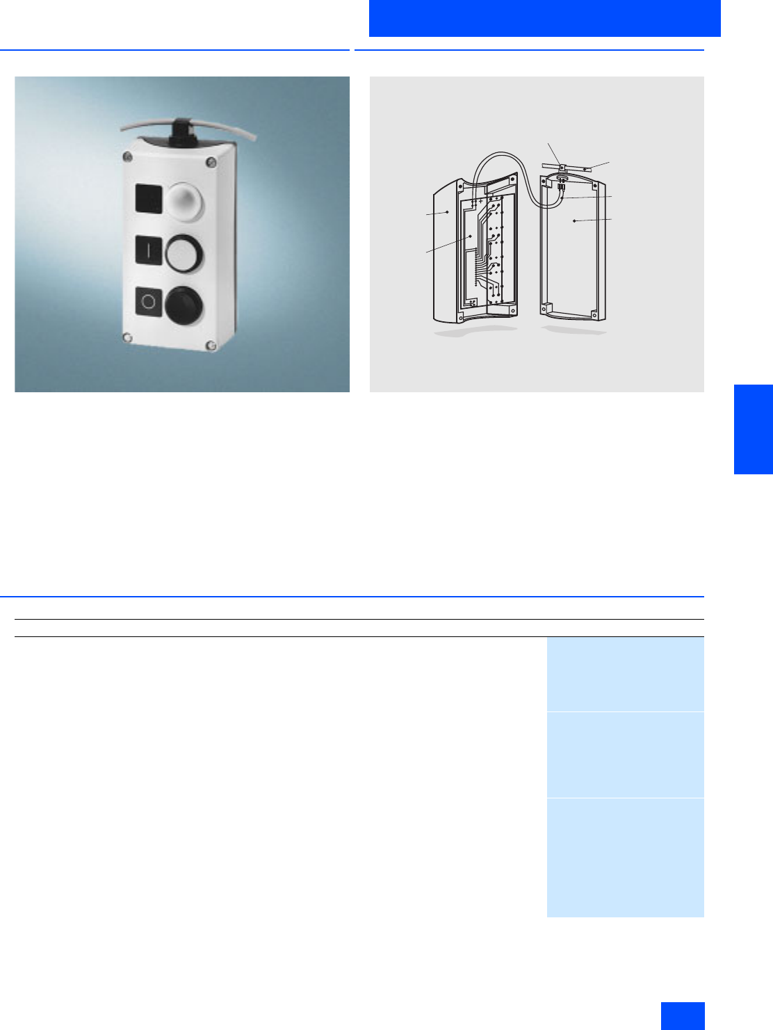
Siemens IK PI · 2004 6/123
AS-Interface Slaves
SIGNUM pushbuttons and indicator lights
AS-Interface enclosure
6
■
Overview
With AS-Interface enclosures, command devices of the SIGNUM
3SB3 installed in a distributed configuration can be quickly con-
nected to AS-Interface.
■
Design
The enclosures without EMERGENCY STOP feature one 4I/4O
application module; an F adapter is mounted on EMERGENCY
STOP enclosures.
The contact blocks and lampholders of the command devices
as well as the AS-Interface slave are soldered onto a carrier
circuit board and screwed onto the command device.
In the case of EMERGENCY STOP enclosures, two normally
closed contact blocks are mounted in the enclosure which are
wired to the F adapter.
Addressing is via the AS-Interface connections or via the built-in
addressing socket. An external supply voltage does not have to
be connected.
■
Selection and Ordering data
N S D 0 _ 0 0 0 5 8
T e r m i n a l
S h a p e d
A S - I n t e r f a c e c a b l e
F l e x i b l e l e a d
( a p p r o x .
2 0 c m l o n g )
E n c l o s u r e p a r t
E n c l o s u r e
c o v e r
P C B
Design
Order No.
AS-Interface enclosure with standard arrangement of components
Arrangement of components
(A, B, C = Code letters for command points)
Number of com-
mand points
A = EMERGENCY STOP mushroom pushbutton via
AS-Interface adapter, yellow bonnet 1
3SF5 801-3AA08
A = EMERGENCY STOP mushroom pushbutton via
AS-Interface adapter, yellow bonnet with protective collar 1
3SF5 801-3AB08
B = Green pushbutton, label "I“
A = Red pushbutton, label "O“ 2
3SF5 802-4DA00
B = White pushbutton, label "I“
A = Black pushbutton, label "O“ 2
3SF5 802-4DB00
C = Clear indicator lamp, label without text
B = Green pushbutton, label "I“
A = Red pushbutton, label "O“
3
3SF5 803-4DA00
C = Clear indicator lamp, label without text
B = White pushbutton, label "I“
A = Black pushbutton, label "O“
3
3SF5 803-4DC00
C = Black indicator lamp, label "II"
B = Black pushbutton, label "I“
A = Red pushbutton, label "O“
3
3SF5 803-4DB00
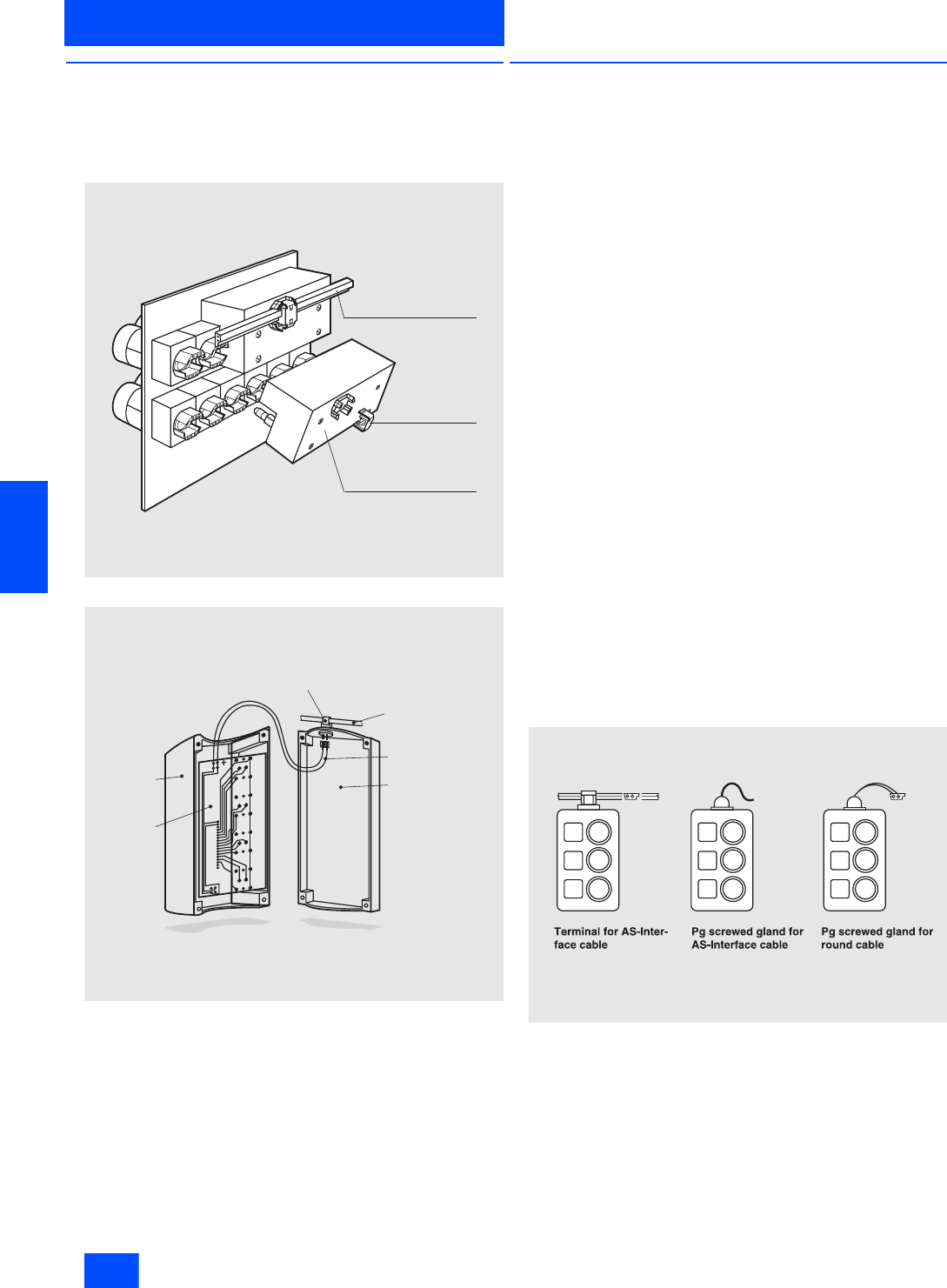
Siemens IK PI · 2004
6/124
AS-Interface Slaves
AS-Interface customized enclosures
and front panel modules
SIGNUM pushbuttons and indicator lights
6
■
Overview
Customized solutions for linking command devices to
AS-Interface permit the configuration of command devices to be
selected as required. In addition to the enclosures, the AS-Inter-
face front panel module provides a solution for SIGNUM 3SB3
Command Devices mounted in front panels.
AS-Interface front panel module
AS-Interface enclosure
■
Design
AS-Interface enclosure
The enclosures with two, three, four and six command points are
equipped with a 4I/4O slave. Up to four inputs (switch contacts)
and four outputs (lamp holders) can therefore be connected to
them. A second slave can be mounted on enclosures for four
and six command points. Addressing is via the AS-Interface
connections or via the built-in addressing socket. An external
supply voltage is not required.
For enclosures with EMERGENCY STOP, the EMERGENCY
STOP actuator can be wired conventionally or alternatively using
the AS-Interface F adaptor.
With conventional wiring, interrogation can be performed via AS-
Interface. In this case, a second slave cannot be mounted on the
enclosure for four command points.
In the case of conventional wiring of the EMERGENCY STOP, up
to three switch contacts can be selected for the EMERGENCY
STOP; if the EMERGENCY STOP is scanned via AS-Interface,
two contacts are possible.
If the EMERGENCY STOP is wired via the F adaptor, the safe
module is mounted above or to the right. The AS-Interface cable
is then looped through to supply the non-safe command devices
of the enclosure. EMERGENCY STOP via an F adaptor is only
possible for enclosures for three, four or six command points.
The following methods can be used for connecting the AS-Inter-
face cable:
• Terminal for shaped AS-Interface cable. Contact is made with
the cable using the insulation piercing method and it is routed
externally past the enclosure.
• Cable gland for the shaped AS-Interface cable or round cable.
The cable is inserted into the enclosure.
• Connection via M12 connectors
• In the case of enclosures with EMERGENCY-STOP via the AS-
Interface F adaptor, the cable is connected using the terminals
mounted on the F adaptor for the shaped AS-Interface cable.
The cable is routed externally past the enclosure.
Typical connections
If not all the inputs and outputs of the slave built into an enclo-
sure are used, the spare inputs and outputs can be routed to the
outside via an M12 socket at the top and bottom of the enclo-
sure. The pin assignment required for the M12 socket must then
be specified on the order supplement (see section Options).
N S D 0 _ 0 0 0 5 3 a
A S - I n t e r f a c e c a b l e
T e r m i n a l
F r o n t p a n e l m o d u l e
N S D 0 _ 0 0 0 5 8
T e r m i n a l
S h a p e d
A S - I n t e r f a c e c a b l e
F l e x i b l e l e a d
( a p p r o x .
2 0 c m l o n g )
E n c l o s u r e p a r t
E n c l o s u r e
c o v e r
P C B
N S A 0 _ 0 0 3 4 6
A S - I n t e r f a c e c a b l e i s
r o u t e d e x t e r n a l l y a l o n g -
s i d e
T h e A S - I n t e r f a c e c a b l e
i s l a i d i n t h e m o d u l e
R o u n d c a b l e i s l a i d i n
t h e m o d u l e

Siemens IK PI · 2004 6/125
AS-Interface Slaves
SIGNUM pushbuttons and indicator lights
AS-Interface customized enclosures
and front panel modules
6
■
Design (continued)
AS-Interface front panel module
The front panel module has one 4I/4O slave, four SIGNUM 3SB3
command devices as well as the necessary mounting accesso-
ries.
The rear of the module is plugged onto a group of four command
devices that are arranged in a vertical or horizontal row and
screwed in place. The command devices must be mounted in a
grid pattern of 30 mm x 45 mm. The shaped AS-Interface cable
is connected via a connection terminal on the rear of the module
using the insulation piercing method.
The module is addressed via the AS-Interface terminals or via
the built-in addressing socket.
■
Selection and Ordering data
1) Ordering example for AS-Interface enclosure with four command
points:
3SF5 804-4AZ
KOY
Equipment according to order supplement
for AS-Interface enclosure
(<- For form for order supplement, see section Options)
2) Ordering example for AS-Interface front panel module:
3SF5 874-4AZ
KOY
Equipment according to order supplement
for AS-Interface front-panel module
(<- For form to complete order supplement, see section Options)
■
Options
To order customized AS-Interface solutions for SIGNUM 3SB3
control devices, please fill out the corresponding enclosed order
form and enclose it with the order.
Enter the desired options into the order form, such as type of
actuating elements, switch contacts, lampholders or accesso-
ries (labels or the like). The codes that are to be entered in the
form can be obtained from the list of options that are subject to
a surcharge.
The price of the device is calculated from the basic price of the
respective version and the additional prices for the comple-
ments (refer to price list).
The additional prices include all components which depend on
the selected configuration options, i.e. type of actuating ele-
ments, contacts, lampholders and accessories, such as labels,
lamps, connections sockets, a second slave etc.
Design
Order No.
AS-Interface enclosure, equipped as required 1)
• Two command points
3SF5 802-4AZ
• Three command points
3SF5 803-4AZ
• Four command points
3SF5 804-4AZ
• Six command points
3SF5 806-4AZ
AS-Interface front-panel module, equipped as required 2)
Four command points
3SF5 874-4AZ
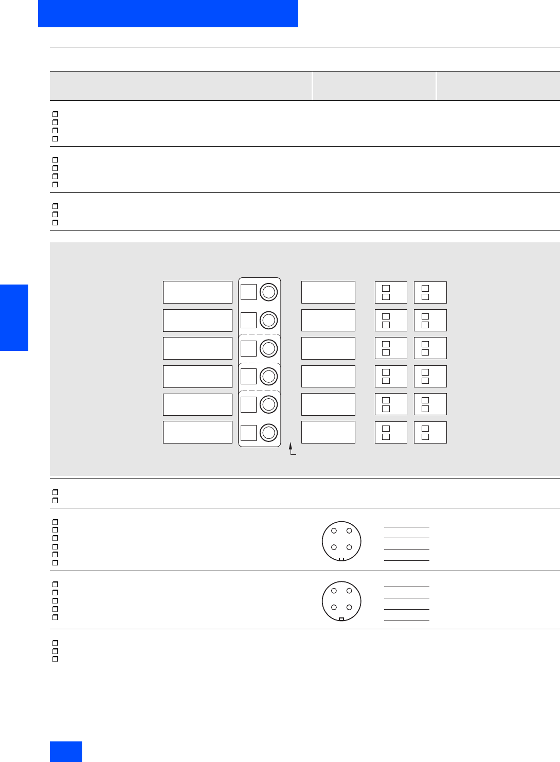
Siemens IK PI · 2004
6/126
AS-Interface Slaves
AS-Interface customized enclosures
and front panel modules
SIGNUM pushbuttons and indicator lights
6
Order form for AS-Interface housing
Order form to Siemens AG, A&D CD GKA LZA
Amberg, fax: +49 96 21 80-31 02
Date Order ID of purchaser/order ID I Order ID of supplier
1. Size of housing
two command points
three command points
four command points
six command points
2. EMERGENCY STOP actuator (only possible at point “A“)
without EMERGENCY STOP
with non-interrogated EMERGENCY STOP (only possible with 3, 4 and 6 points)
with interrogated EMERGENCY STOP (only possible with 3, 4 and 6 points)
with safe AS-Interface adaptor
3. Yellow area for EMERGENCY STOP (only fill out if available)
without yellow stripes
with yellow stripes, without inscription at point “A“
with yellow stripes, with inscription at point “A“ (state inscription under point 4)
4. Inscription and configuration
5. Installation orientation
vertical (identific. plates on the left)
horizontal (identification plates on top)
6. Terminal on top resp. on the right
no cable gland (drill-hole is not pressed out)
terminal for by-passed AS-Interface cable
metric cable gland for inserted AS-Interface cable
metric cable gland for inserted round cable
M12 socket for free input or output
AS-Interface F adaptor (only for housings with EMERGENCY STOP)
7. Terminal on top resp. on the left
no cable gland (drill-hole is not pressed out)
terminal for by-passed AS-Interface cable
metric cable gland for inserted AS-Interface cable
metric cable gland for inserted round cable
M12 socket for free input or out
8. Lamps
incandescent lamp 24V (if no option is marked, an incandescent lamp 24 V will be used)
incandescent lamp 30V
super bright LED (LED color is same as the color of the actuating element/signalling device)
F
E
D
C
B
A
NSD0_00062d
Left position
1 NO
1 NC
Right position
1 NO
1 NC
1 NO
1 NC
1 NO
1 NC
1 NO
1 NC
1 NO
1 NC
1 NO
1 NC
1 NO
1 NC
1 NO
1 NC
1 NO
1 NC
1 NO
1 NC
1 NO
1 NC
Inscription of the inscription plates
(max. 11 letters, 1 to 3 lines)
Actuators
(abbreviations)
Standard: 1 normally-open
contact (1 NO),
if not otherwise indicated
A to F are identification letters on the inside
of the covers and bases
34
2 1
N S S 0 _ 0 0 4 5 6 b
P i n 1 :
P i n 2 :
P i n 3 :
P i n 4 :
34
2 1
N S S 0 _ 0 0 4 5 6 b
P i n 1 :
P i n 2 :
P i n 3 :
P i n 4 :
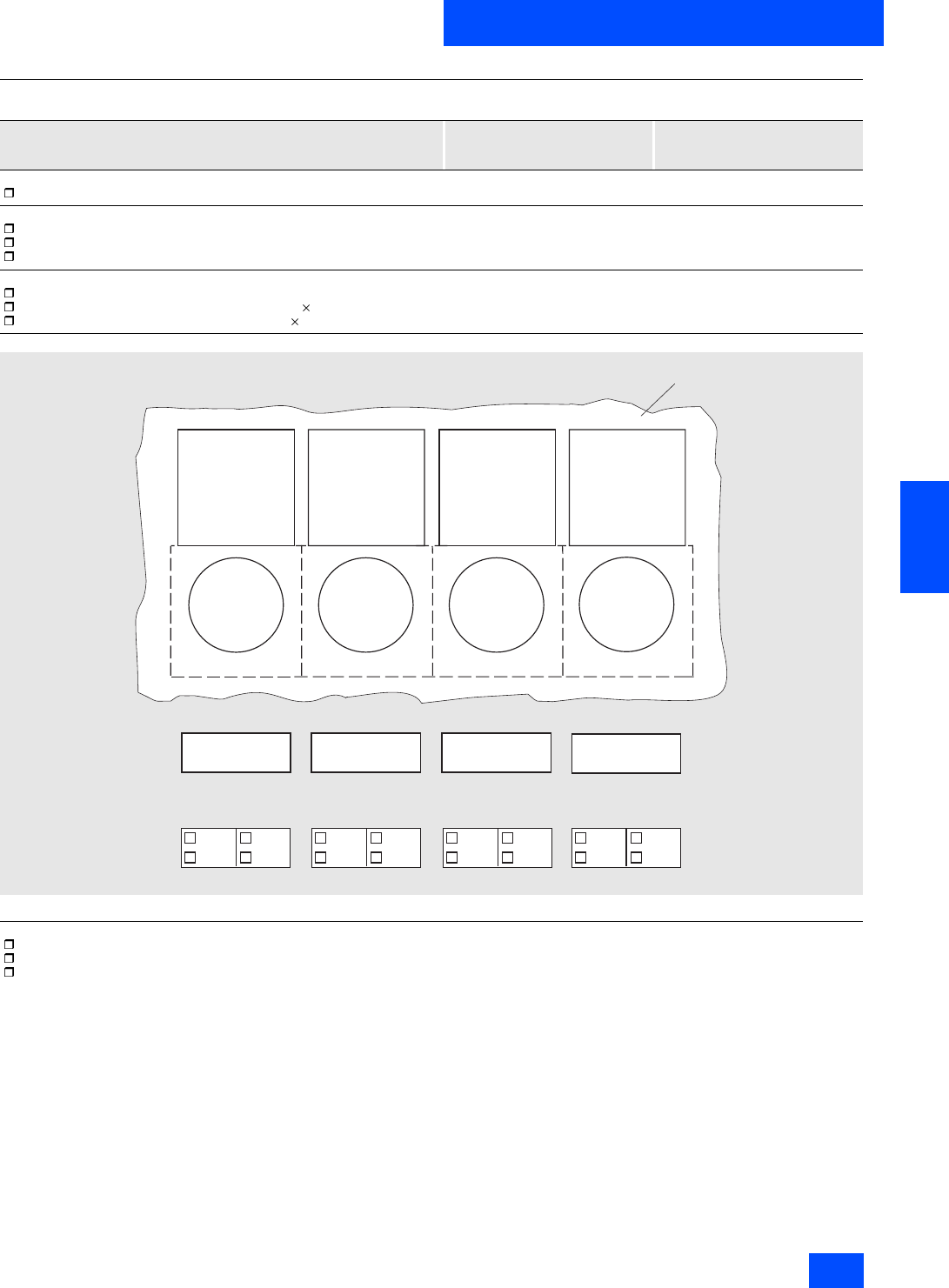
Siemens IK PI · 2004 6/127
AS-Interface Slaves
SIGNUM pushbuttons and indicator lights
AS-Interface customized enclosures
and front panel modules
6
Order form AS-Interface front panel modules
Order form to Siemens AG, A&D CD GKA LZA
Amberg, fax: +49 96 21 80-31 02
Date Order ID of purchaser/order ID I Order ID of supplier
1. Number of command points
four command points
2. Design of actuating elements
round, molded plastic
square, molded plastic
round, metal
3. Name plates
without
with name plate including legend plate 12.5 mm 27 mm glued in
with name plate including legend plate 27 mm 27 mm glued in
4. Configuration
Top view of front side of switchboard
5. Lamps
incandescent lamp 24V (if no option is marked, an incandescent lamp 24 V will be used)
incandescent lamp 30V
super bright LED (LED color is same as the color of the actuating element/signalling device)
A B
C D
1 S
1 Ö
1 S
1 Ö
1 S
1 Ö
1 S
1 Ö
1 S
1 Ö
1 S
1 Ö
1 S
1 Ö
1 S
1 Ö
N S D 0 _ 0 0 0 5 7 c
S w i t c h b o a r d
l e f t r i g h t l e f t r i g h t l e f t r i g h t l e f t r i g h t

Siemens IK PI · 2004
6/128
AS-Interface Slaves
AS-Interface customized enclosures
and front panel modules
SIGNUM pushbuttons and indicator lights
6
Options for AS-Interface housing and AS-Interface front panel modules subject to a surcharge
1) For more detailed information about individual actuating elements,
see Section Pushbuttons and Light Indicators / SIGNUM 3SB3 / Pushbuttons and Pressure Switches onward.
2) Cannot be used with front panel module.
Code for design/color of controls
black red yellow green blue white clear
Actuating elements and signalling devices 1)
(subject ot a surcharge)
Blank plug for 22.5 mm 2) BV BK ––––––
Pushbutton with flat button D BK D RD D YE D GN D BU D WH D CL
Illuminated pushbutton with flat
button –DL RD DL YE DL GN DL BU DL WH DL CL
Pushbutton with protruding button DH BK DH RD DH YE DH GN DH BU DH WH –
Illuminated pushbutton with
protruding button –DHL RD DHL YE DHL GN DHL BU –DHL CL
Pushbutton with protruding
mounting ring DHF BK DHF RD DHF YE DHF GN DHF BU DHF WH –
Pushbutton with protruding
mounting ring, castellated DFZ BK DFZ RD DFZ YE DFZ GN DFZ BU DFZ WH –
Pressure switch with flat pushbutton DS BK DS RD DS YE DS GN DS BU DS WH –
Illuminated pressure switch with flat
pushbutton –DLS RD DL YE DLS GN DLS BU DLS WH DLS CL
Mushroom-head pushbutton,
Ø 30 mm 2) P30 BK P30 RD P30 YE P30 GN –––
Illuminated mushroom-head
pushbutton, Ø 30 mm 2) ––PL30 YE PL30 GN –PL30 WH –
Mushroom-head pushbutton,
Ø 40 mm 2) P BK P RD P YE P GN –––
Illuminated mushroom-head
pushbutton, Ø 40 mm 2) –PL RD PL YE PL GN –––
Pushbutton with protruding button,
latches after pushing in by turning
it to the right, unlatches by turing
it to the left 2)
DHR BK DHR RD –––––
EMERGENCY STOP mushroom/
head pushbutton acc. to EN 418,
Ø 40 mm, latches automatically 2)
• Unlatches by turning it to the left 2) –PRÜ 40 RD –––––
• With RONIS lock, lock no. SB30 2) –PRS 30 RD –––––
• With CES lock, lock no. SB10 2) –PRS 10 RD –––––
• With BKS lock, lock no. S1 2) –PRS S1 RD –––––
• With O.M.R. lock, lock no. 73037 2) –PRS 73 RD –––––
Light indicator –L RD L YE L GN L BU L WH L CL
Push-pull button 2)
• Ø 30 mm 2) DZ 30 BK DZ30 RD –––––
• Ø 30 mm, can be illuminated 2)–DZB30 RD DZB30 YE DZB30 GN DZB30 BU –DZB30 CL
• Ø 40 mm 2) DZ BK DZ RD –––––
• Ø 40 mm, can be illuminated 2) –DZB RD DZB YE DZB GN DZB BU –DZB CL
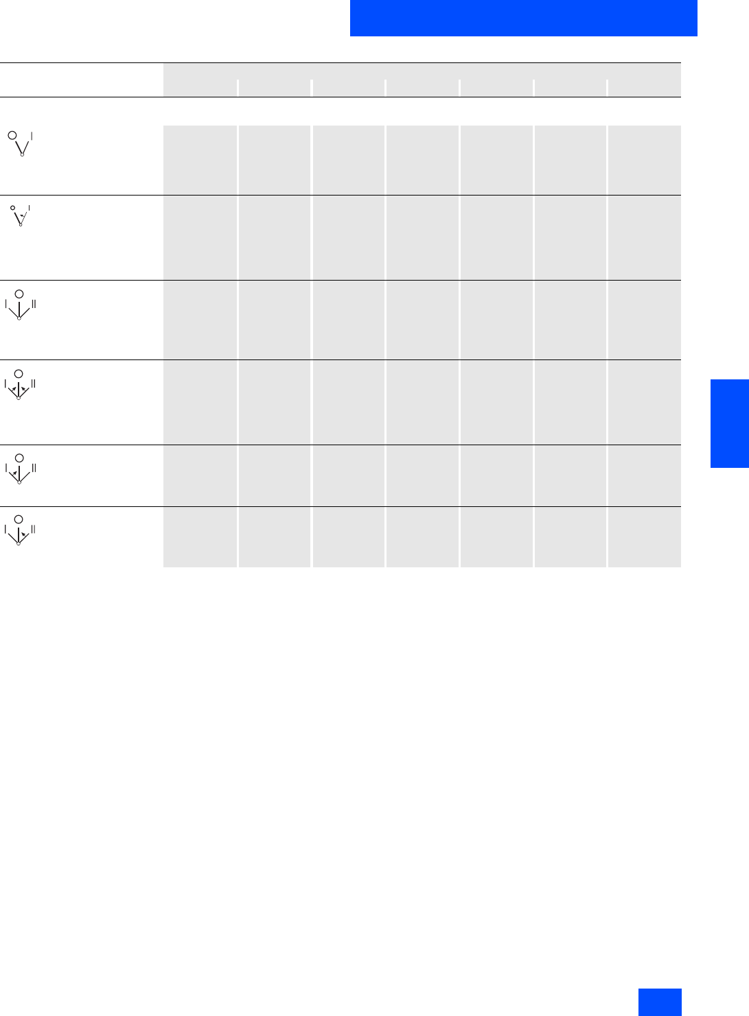
Siemens IK PI · 2004 6/129
AS-Interface Slaves
SIGNUM pushbuttons and indicator lights
AS-Interface customized enclosures
and front panel modules
6
Options for AS-Interface housing and AS-Interface front panel modules subject to a surcharge (continued)
1) For more detailed information about individual actuating elements,
see Section Pushbuttons and Light Indicators / SIGNUM 3SB3 / Pushbuttons and Pressure Switches onward.
Code for design/color of controls
black red yellow green blue white clear
Knob 1)
(subject to a surcharge))
Switching sequence
O–I latching
• not illuminated K1 BK K1 RD –K1 GN –K1 WH –
• illuminated –BK1 RD BK1 YE BK1 GN BK1 BU –BK1 CL
Switching sequence
O–I pushbutton control
(with resetting from the
right)
• not illuminated K2 BK K2 RD –K2 GN –K2 WH –
• illuminated –BK2 RD BK2 YE BK2 GN BK2 BU –BK2 CL
Switching sequence
I-O-II latching
• not illuminated K4 BK K4 RD –K4 GN –K4 WH –
• illuminated –BK4 RD BK4 YE BK4 GN BK4 BU –BK4 CL
Switching sequence
I-O-II pushbutton con-
trol (with resetting from
the right and left)
• not illuminated K5 BK K5 RD –K5 GN –K5 WH –
• illuminated –BK5 RD BK5 YE BK5 GN BK5 BU –BK5 CL
Switching sequence
I-O-II, latches on the
right, pushbutton con-
trol on the left (with
resetting from the left)
K6 BK K6 RD –K6 GN –K6 WH –
Switching sequence
I-O-II, latches on the
left, pushbutton control
on the right (with reset-
ting from the right)
K7 BK K7 RD –K7 GN –K7 WH –

Siemens IK PI · 2004
6/130
AS-Interface Slaves
AS-Interface customized enclosures
and front panel modules
SIGNUM pushbuttons and indicator lights
6
Options for AS-Interface housing and AS-Interface front panel modules subject to a surcharge (continued)
1) Required when more than four inputs or more than four outputs are required for supplying the control devices.
Code for design/key removal position of locks
O I II O and I O and II I and II I, O and II
Locks 1)
(subject to a surcharge)
Switching sequence
O–I latching
• Type RONIS, flat
- Lock no. SB30 RSB 1A RSB 1E –RSB 1AE –––
• Type CES
- Lock no. SSG 10 CES 1A CES 1E –CES 1AE –––
- Lock no. LSG 1 CESL 1A ––CESL 1AE –––
•Type IKON
- Lock no. 360012 K1 Z-J 1A ––Z-J 1AE –––
• Type BKS
- Lock no. S1 BKS 1A BKS 1E –BKS 1AE –––
- Lock no. E1 (for VW) BKS A 1A ––BKS A 1AE –––
- Lock no. E2 (for VW) BKS E 1A ––BKS E 1AE –––
- Lock no. E7 (for VW) BKS C 1A ––BKS C 1AE –––
- Lock no. E9 (for VW) BKS B 1A ––BKS B 1AE –––
• Type O.M.R., black
- Lock no. 73034 OMR BK 1A OMR BK 1E –OMR BK 1AE –––
Switching sequence
O–I pushbutton con-
trol (with resetting
from the right)
• Type RONIS, flat
- Lock no. SB30 RSB 2A ––––––
• Type CES
- Lock no. SSG 10 CES 2A ––––––
- Lock no. LSG 1 CESL 2A ––––––
•Type IKON
- Lock no. 360012 K1 Z-J 2A ––––––
• Type BKS
- Lock no. S1 BKS 2A ––––––
• Type O.M.R., black
- Lock no. 73034 OMR BK 2A ––––––
Switching sequence
I-O-II latching
• Type RONIS, flat
- Lock no. SB30 RSB 4A RSB 4E RSB 4D – – RSB 4ED RSB 4EAD
• Type CES
- Lock no. SSG 10 CES 4A CES 4E CES 4D – – CES 4ED CES 4EAD
•Type IKON
- Lock no. 360012 K1 Z-J 4A Z-J 4E Z-J 4D – – Z-J 4ED Z-J 4EAD
• Type BKS
- Lock no. S1 BKS 4A BKS 4E BKS 4D – – BKS 4ED BKS 4EAD
• Type O.M.R., black
- Lock no. 73034 OMR BK 4A ––––OMR BK 4ED OMR BK
4EAD
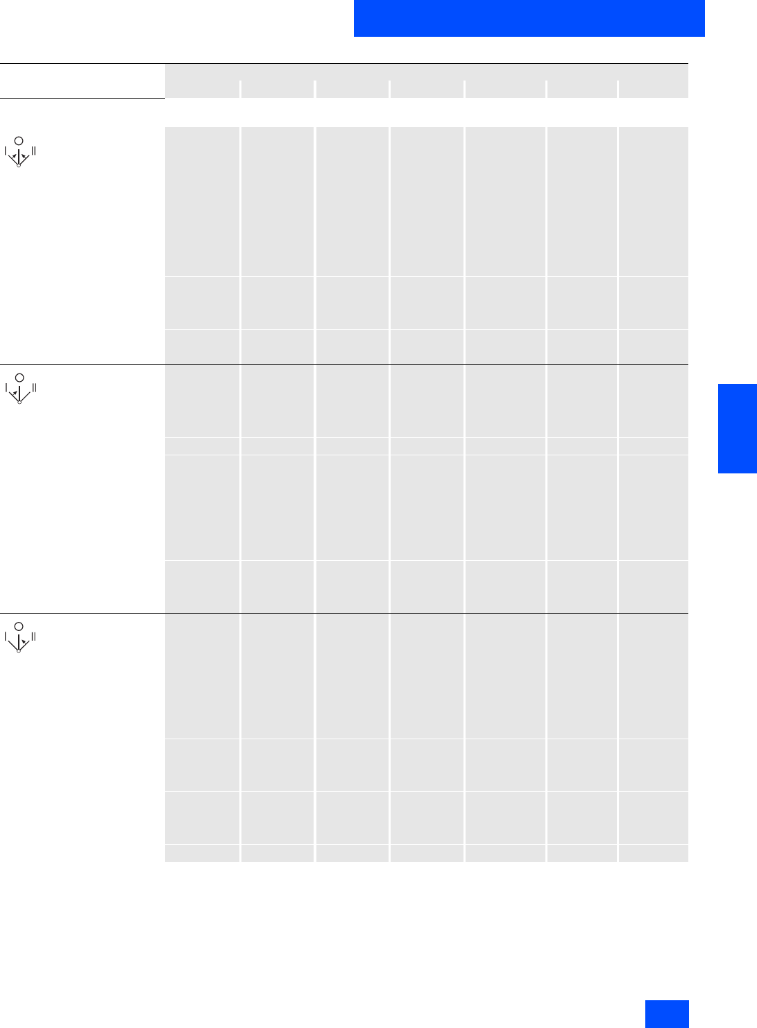
Siemens IK PI · 2004 6/131
AS-Interface Slaves
SIGNUM pushbuttons and indicator lights
AS-Interface customized enclosures
and front panel modules
6
Options for AS-Interface housing and AS-Interface front panel modules subject to a surcharge (continued)
1) Required when more than four inputs or more than four outputs are required for supplying the control devices.
Code for design/key removal position of locks
O I II O and I O and II I and II I, O and II
Locks 1)
(subject to a surcharge)
Switching sequence
I-O-II pushbutton
control (with resetting
from the right and
left)
• Type RONIS, flat
- Lock no. SB30 RSB 5A – – – – – –
• Type CES
- Lock no. SSG 10 CES 5A – – – – – –
•Type IKON
- Lock no. 360012 K1 Z-J 5A – – – – – –
• Type BKS
- Lock no. S1 BKS 5A – – – – – –
• Type O.M.R., black
- Lock no. 73034 OMR BK 5A – – – – – –
Switching sequence
I-O-II, latches on the
right, pushbutton
control on the left (with
resetting from the
left)
• Type RONIS, flat
- Lock no. SB30 RSB 6A –RSB 6D –RSB 6AD – –
• Type CES
- Lock no. SSG 10 CES 6A –CES 6D –CES 6AD – –
•Type IKON
- Lock no. 360012 K1 Z-J 6A –Z-J 6D –Z-J 6AD – –
• Type BKS
- Lock no. S1 BKS 6A –BKS 6D –BKS 6AD – –
• Type O.M.R., black
- Lock no. 73034 OMR BK 6A –OMR BK 6D –OMR BK 6AD – –
Switching sequence
I-O-II, latches on the
left, pushbutton control
on the right (with
resetting from the
right)
• Type RONIS, flat
- Lock no. SB30 RSB 7A RSB 7E –RSB 7AE – – –
• Type CES
- Lock no. SSG 10 CES 7A CES 7E –CES 7AE – – –
•Type IKON
- Lock no. 360012 K1 Z-J 7A Z-J 7E –Z-J 7AE – – –
• Type BKS
- Lock no. S1 BKS 7A BKS 7E –BKS 7AE – – –
• Type O.M.R., black
- Lock no. 73034 OMR BK 7A OMR BK 7E – – – – –
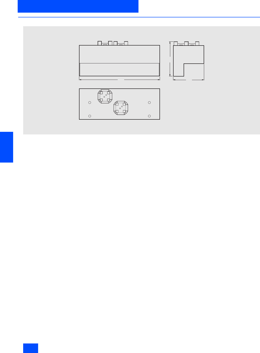
Siemens IK PI · 2004
6/132
AS-Interface Slaves
AS-Interface customized enclosures
and front panel modules
SIGNUM pushbuttons and indicator lights
6
■
Dimensional drawings
AS-Interface front panel module
120
5 2
4 5
N S D 0 0 2 3 6
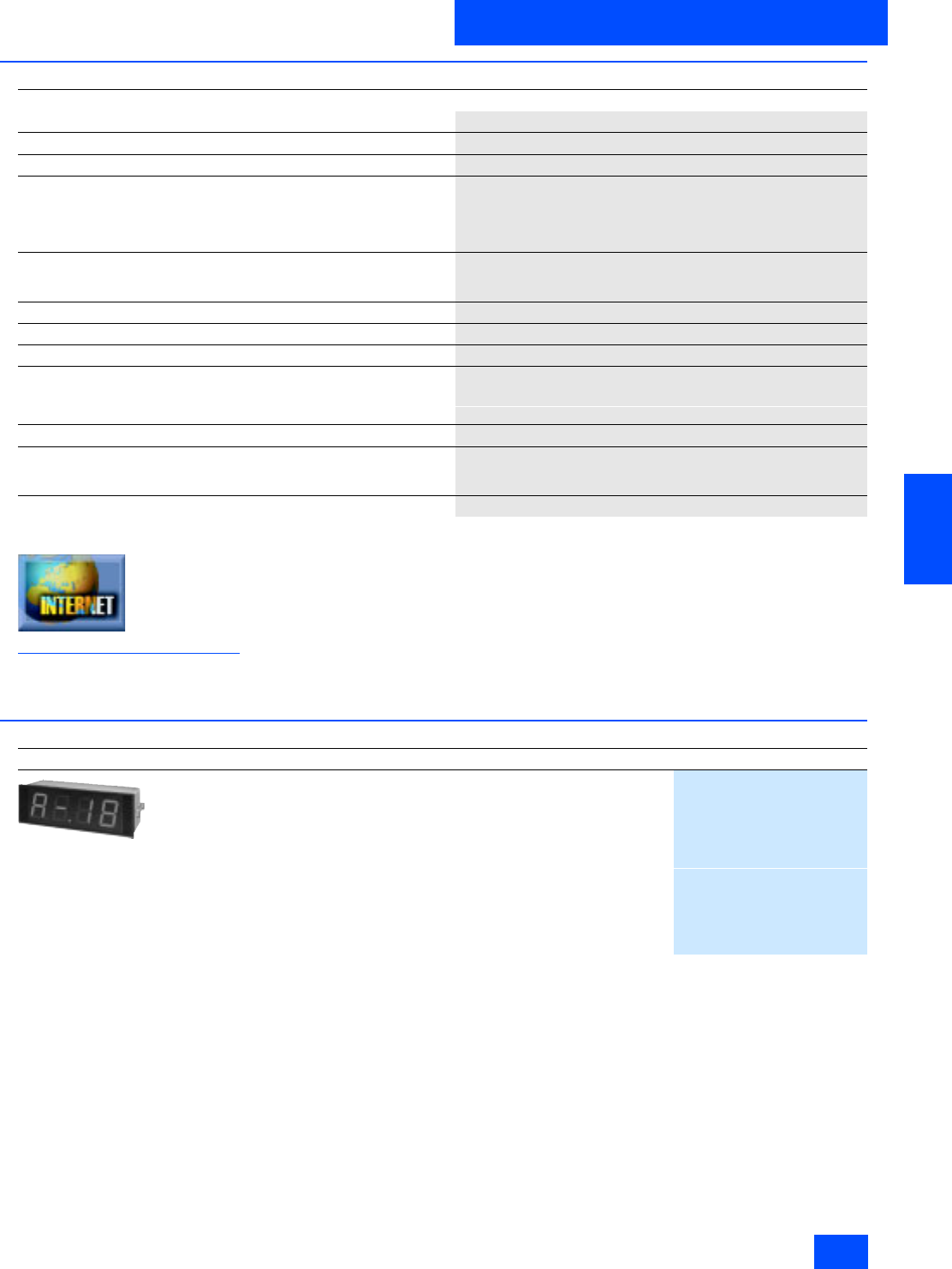
Siemens IK PI · 2004 6/133
AS-Interface Slaves
SIGNUM pushbuttons and indicator lights
AS-Interface LED displays
6
■
Technical specifications
Additional information is available in the Internet under:
http://www.siemens.de/bediensysteme
Function block program examples and GSD files can be
downloaded from the Internet.
■
Selection and Ordering data
1) Function block-example programs, which are included with every delivery,
are available for connecting to the PLC (S5, S7-300, S7-400).
AS-Interface LED displays
Type of display LED 7-segment
Color of light Red or green
Operating voltage in V DC 24 (for AS-Interface via AS-i bus)
Power consumption for digit height
• 13 mm 0.15 W per digit
• 30 mm 0.3 W per digit
• Display with AS-i bus 0 to 9 and A, b, -, uninsulated
Addresses 1 address per display.
With AS-Interface: After the 15th addressing, the display keeps the last
address.
Housing Bay housing to DIN, metal
Mounting Screw bracket to DIN
Degree of protection IP54 to the front; with AS-Interface IP65
Ambient temperature
• During operation in °C 0 to +50
• During storage in °C -25 to +70
EMC Acc. to the specifications of the 89/336/EWG (or EMVG) guideline
Emitted interference Basic technical standard EN 50 081-2, July 1993 Edition
Product standard EN 55 011, Group 1/2, Class A, March 1991 Edition
Limit value curve identical to EN 55 022
Noise immunity Basic technical standard EN 50 082-2, March 1995 Edition
Design
Order No.
3SF4 102-2D
Numerical LED displays
for installation
with AS-Interface 1)
with additional, electrically isolated, digital inputs
Number of places: 4
Character height, positions Color
13 mm, 4 places Red
3SF4 102-1B
Green
3SF4 102-2B
30 mm, 4 places Red
3SF4 102-1D
Green
3SF4 102-2D
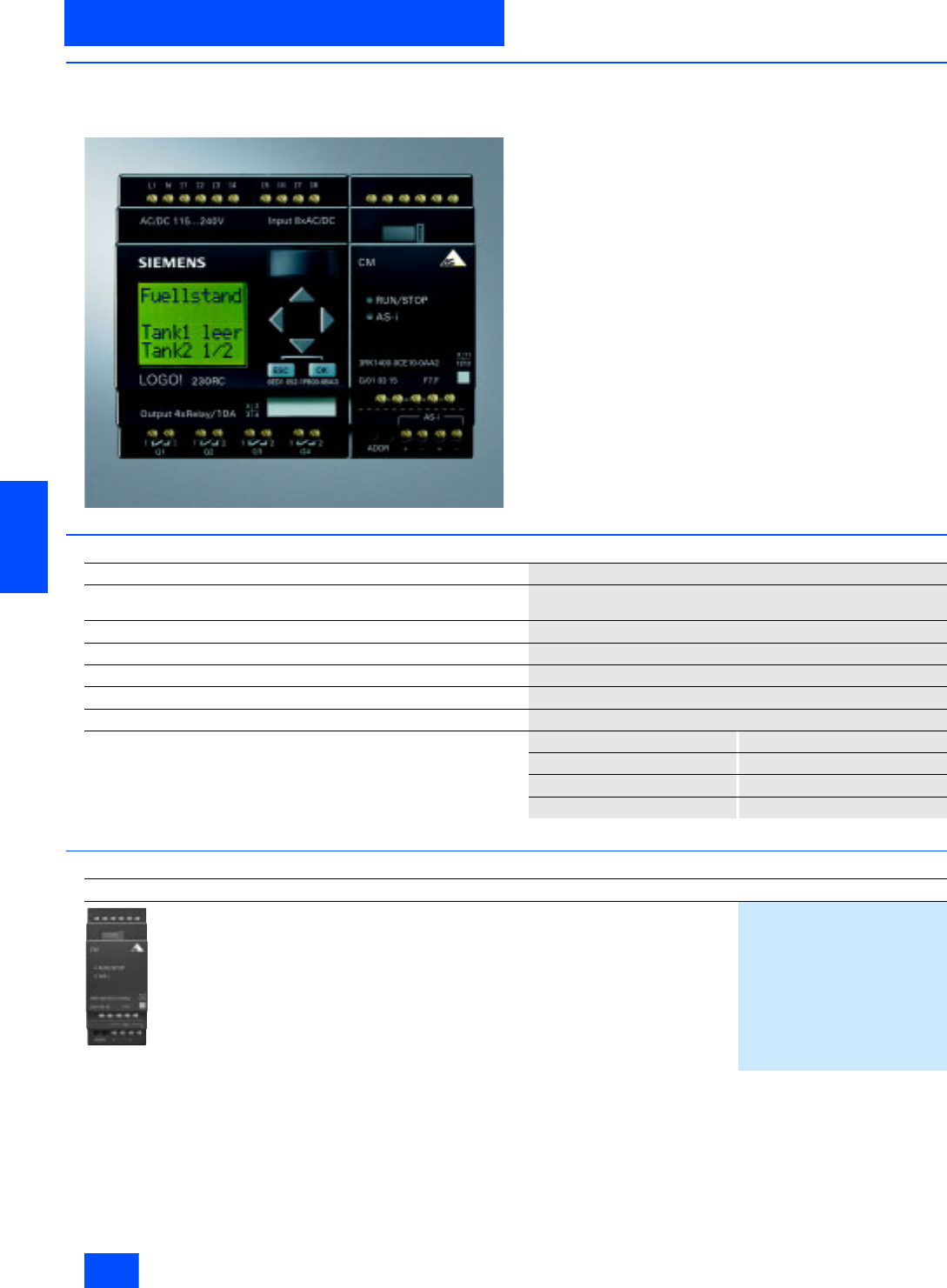
Siemens IK PI · 2004
6/134
AS-Interface Slaves
AS-Interface for LOGO!
6
■
Overview
Each LOGO! now connectable to the AS-Interface system
-new-
With the AS-Interface for LOGO! an intelligent slave can be inte-
grated into the AS-Interface system. Modular integration permits
different basic units to be integrated into the system whenever
the functionality is required. The functionality can also be quickly
and easily adapted to changing requirements by replacing the
basic unit
The interface provides four inputs and four outputs for the sys-
tem These I/Os, however, are not actually implemented in hard-
ware; they only exist virtually via the interface on the bus
■
Technical specifications
■
Selection and Ordering data
Supply voltage in V 24 V DC
Inputs/outputs 4 / 4
(virtual inputs / outputs)
Bus connection AS-Interface according to specification
Ambient temperature in °C 0 to +55
Degree of protection IP20
Mounting onto standard mounting rail
Dimensions (W x H x D) in mm 36 x 90 x 58
Display of LEDs LEDs Status
green OK
red No data traffic
red/yellow flash Zero address
Design
Order No.
3RK1 400-0CE10-0AA2
AS-Interface connection for LOGO!
3RK1 400-0CE10-0AA2
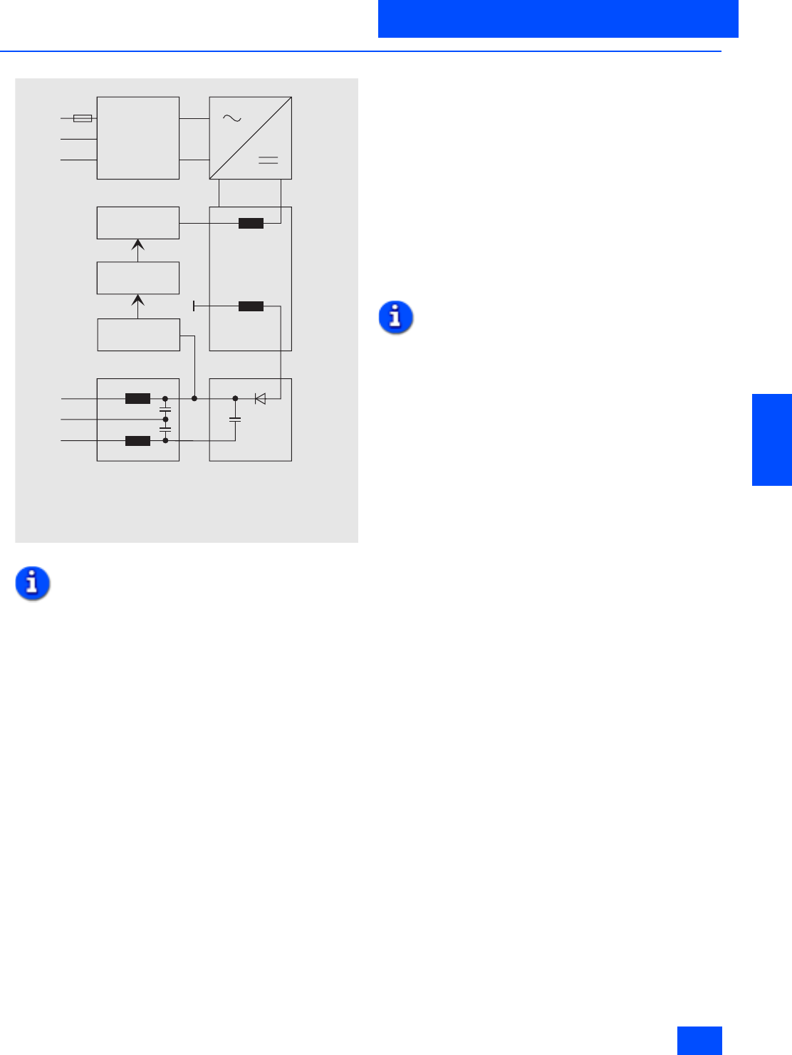
Siemens IK PI · 2004 6/135
AS-Interface Power Supply Units
Introduction
6
■
Overview
General design of the AS-Interface power supplies
Note:
The "ground" connection to the system earth must always be as
short as possible.
AS-Interface power supplies are part of the necessary and most
important components of an AS-Interface system.
AS-Interface power supplies generate a stabilized DC voltage of
30 V DC with a high constancy and low residual ripple. They
work in the same way as primary switched-mode regulators.
Data and power are always transmitted simultaneously via the
AS-Interface two-wire cable. For this reason, AS-Interface power
supplies must also ensure data decoupling in addition to supply-
ing the AS-Interface system.
For this reason, standard power supplies must not be used for
the supply of an AS-Interface system.
AS-Interface power supplies supply the electronics of the sys-
tem (AS-Interface master, AS-Interface modules) and all con-
nected sensors. Depending on the power requirements of the
AS-Interface system, graduated power supplies from 2.4 to 7 A
are available.
Please note that there are different power supplies for the sen-
sors and actuators.
The power for the actuators (outputs) is usually not supplied by
the AS-Interface cable. This must be done by a separate load
power supply unit which must be connected via a separate
cable (e.g. black AS-Interface flat cable). It can also be used to
implement corresponding emergency stop circuits.
If an auxiliary power supply is required in addition to the
AS-Interface voltage, the very compact combination power
supply unit with 1 x 30 V DC and 1 x 24 V DC can be used.
If so-called double masters are used, the dual power supply unit
with 2 x 30 V can be used.
Performance characteristics:
• high efficiency
• low residual ripple
• short-circuit proof and stable at no load
• overvoltage protection at input
• small dimensions
•low weight
• simple and fast assembly
All AS-Interface power supplies have an AS-Interface certificate.
Power supplies with UL, CSA, and ship construction approba-
tion are available for worldwide use.
Note:
An additional external infeed (AUX POWER) of 20 to 30 V DC is
required for the supply of the output circuits. The additional
infeed must comply with VDE 0106 (PELV), protection class I.
Earth fault detection
“... earth faults in control circuits must not result in unintended
startup or dangerous movements of the machine nor must they
prevent the machine from stopping (EN 60 204, Part 1 or
DIN VDE 0113)”.
To fulfill these requirements, the AS-Interface earth fault detec-
tion module or power supplies with earth fault detection are
used. These modules permit earth faults in AS-Interface systems
to be safely detected and signaled.
The following earth faults are recognized:
• AS-i ”+” earth fault
• AS-i ”-” earth fault
• Earth faults of sensors and actuators which are supplied by the
AS-Interface voltage.
One module for each AS-Interface system is sufficient.
N S A 0 _ 0 0 1 1 6 a
L 1
A S - i +
G r o u n d
N
P E
F 1
A S - i
Input
f i l t e r
T o p s w i t c h
O p t o c o u p l e r
C o n t r o l l e r
I s o l a t i o n
S m o o t h i n g
N o t e :
T h e " G R O U N D " m u s t a l w a y s b e c o n n e c t e d t o t h e s y s t e m e a r t h
i n t h e s h o r t e s t p o s s i b l e w a y .
$6,QWHUIDFH3RZHU6XSSO\8QLWV

Siemens IK PI · 2004
6/136
AS-Interface Power Supply Units
Power supply units IP20
6
■
Technical specifications
AS-Interface power supply unit
Single output IP20
Output current 2.4 A Output current 4 A Output current 3.3 A
3RX9 307-0AA00 3RX9 307-1AA00 4FD5 213-0AA10-1A
Rated input voltage in V 115/230 AC 115/230 AC 230/400 AC
Input Single-phase AC Single-phase AC Single- and two-phase AC
• Range selection With changeover switch With plug
• Voltage range in V 195 to 253 / 102 to 132 AC 197 to 430 AC
• Overvoltage strength EN 61 000-4-1
• Mains buffering at e Rated in ms > 20 > 20 at 230 V; > 60 at 400 V
• Mains frequency rated value I
range in Hz 50/60/47 to 63
• Built-in input fuse in A T 2 T 5 (not accessible) T 3 (not accessible)
• Recommended m.c.b (IEC898)
in mains supply circuit in A From 10, characteristic C From 10, characteristic C From 16, characteristic C
Output
• Stabilized floating DC voltage acc.
to AS-Interface specification Yes Yes, can be connected in parallel
• Voltage rating UaRated in V 30 DC
• Total tolerance in V 29.5 to 31.6 DC
• Residual ripple in mVpp
(0–10 kHz, AS-i+/AS-i–) < 300
• Spikes in mVpp
(10–500 kHz, AS-i+/AS-i–) < 50
• Operational display Green LED
• Current rating a Rated in A 2.4 (power boost: 2.8) 4 (power boost: 4.5) DC 3.3 (power boost: DC 4)
Efficiency/power loss
• Efficiency at UaRated, aRated in % Approx. 85
• Power loss at UaRated, aRated in W Approx. 10 Approx. 18 Approx. 15
Protective and monitoring functions
• Output overvoltage protection No
• Current limitation in A > 2.8 > 5
• Short-circuit protection Yes
Safety
• Primary/secondary isolation SELV to EN 60 950 SELV to EN 60 950 (in preparation) SELV to EN 60 950
• Safety class (EN 60 950/IEC 950) I
• Degree of protection IP20
• Approvals CE, UL, marine CE, UL, CSA (in preparation) CE, UL (in preparation)
EMC
• Emitted interference EN 50 081-1
• Noise immunity EN 50 082-2
Operational data
• Ambient temperature range in °C -25 to +55 -45 to +55
• Transport and storage
temperature range in °C -25 to +60 -45 to +80
• Humidity class Max. 80% rel. humidity
Mechanical data
• Input connection Spring-loaded terminal connection (0.8 to 2.5 mm2)
• Output connection AS-i + Spring-loaded terminal connection (0.8 to 2.5 mm2)
• Output connection AS-i - Spring-loaded terminal connection (0.8 to 2.5 mm2)
• Output connection shield S Spring-loaded terminal connection (0.8 to 2.5 mm2)
• Output connection Ground - - Spring-loaded terminal connection
(0.8 to 2.5 mm2)
• Dimensions (W x H x D) in mm 46 135 105 75 135 107 75 135 103
• Mounting Snap-on mounting onto standard rail
DIN EN 50 022-35 x 7.5 mm Mounting onto standard rail

Siemens IK PI · 2004 6/137
AS-Interface Power Supply Units
Power supply units IP20
6
■
Technical specifications (continued)
AS-Interface power supply unit
Dual output IP20 Combi output IP20
2 30 V DC 1 24 V DC / 1 30 V DC
3RX9 305-1AA00 3RX9 306-1AA00
Output current in A 4/4 5/4
Input voltage in V 115/230 AC (selectable)
Input Single-phase AC
• Range selection With changeover switch
• Input voltage range in V 195 to 253 / 102 to 132 AC
• Overvoltage strength EN 61 000-4-1
• Mains buffering at e Rated in ms > 20
• Mains frequency rated value I
range in Hz 50/60/47 to 63
• Built-in input fuse in A T 5 (not accessible)
• Recommended m.c.b (IEC898)
in mains supply circuit in A From 16, characteristic C
Output
• Stabilized floating DC voltage
acc. to AS-Interface specification Yes
• Voltage rating UaRated in V 2 x 30 DC 30 DC/24 DC
• Total tolerance 29.5 to 31.6 DC 29.5 to 31.6 DC/24 DC 2 %
• Residual ripple in mVpp
(0–10 kHz, AS-i+/AS-i–) < 300
• Spikes in mVpp
(10–500 kHz, AS-i+/AS-i–) < 50
• Operational display Green LED
• Current rating a Rated in A 2x4 4/5
Efficiency/power loss
• Efficiency at UaRated, aRated in % Approx. 85
• Power loss at UaRated, aRated in W Approx. 36
Protective and monitoring functions
• Overvoltage protection of outputs No
• Current limitation in A > 4 (power boost 4.5) > 4/> 5 (power boost 4.5 / 5.5)
• Short-circuit protection Yes
Safety
• Primary/secondary isolation SELV to EN 60 950 SELV to EN 60 950 (in preparation)
• Safety class (EN 60 950/IEC 950) I
• Degree of protection IP20
• Approvals CE, UL, CSA CE, UL, CSA (in preparation)
EMC
• Emitted interference EN 50 081-1
• Noise immunity EN 50 082-2
Operational data
• Ambient temperature range in °C -45 to +55
• Transport and storage
temperature range in °C -45 to +60
• Humidity class Max. 80% rel. humidity
Mechanical data
• Input connection Spring-loaded terminal connection (0.8 to 2.5 mm2)
• Output connection AS-i + Spring-loaded terminal connection (0.8 to 2.5 mm2)
• Output connection AS-i - Spring-loaded terminal connection (0.8 to 2.5 mm2)
• Output connection shield S Spring-loaded terminal connection (0.8 to 2.5 mm2)
• Dimensions (W x H x D) in mm 150 x 135 x 107
• Mounting Snap-on mounting onto standard rail DIN EN 50 022-35 x 7.5 mm

Siemens IK PI · 2004
6/138
AS-Interface Power Supply Units
Power supply units IP20
6
■
Technical specifications (continued)
AS-Interface power supply unit
Single Output IP20 With integrated earth-fault detection
6EP1 354-1AL01 3RX9 310-0AA00
Output current in A 72.4
Rated input voltage in V 120 to 230 AC 115/230 AC
Input
• Range selection With variable range input With changeover switch
• Voltage range in V 93 to 264 AC / 110 to 350 DC 195 to 253 / 102 to 132 AC
• Overvoltage strength VDE 0160 Limiting curve W2 EN 61 000-4-1
• Mains buffering at Ie Rated in ms < 20 at 93/187 V > 20
• Mains frequency rated value I
range in Hz 0/50/60/47 to 63
• Built-in input fuse in A T 6.3 (not accessible) T 2
• Recommended circuit-breakers
(IEC 898) in A From 16, characteristic C or
from 8, characteristic B From 10, characteristic C
Output
• Stabilized floating DC voltage
acc. to AS-Interface specification Yes
• Voltage rating UaRated in V 30 DC
• Total tolerance 29.5 to 31.6 DC
• Residual ripple in mVpp
(0–10 kHz, AS-i+/AS-i–) < 300
• Spikes in mVpp
(10–500 kHz, AS-i+/AS-i–) < 50
• Operational display Green LED
• Current rating Ia Rated in A 72.4 (power boost: 2.8)
Efficiency/power loss
• Efficiency at UaRated, IaRated in % > 85
• Power loss at UaRated, IaRated in W < 37 10
Protective and monitoring functions
• Overvoltage protection of outputs Yes No
• Current limitation in A From approx. 7.4 > 2.8
• Short-circuit protection Stabilized current characteristic approx. 7.4 A Yes
Safety
• Primary/secondary isolation SELV to EN 60 950
• Safety class (EN 60 950/IEC 950) Class I to IEC 536 I
• Degree of protection IP20 to EN 60 529 IP20
• Approvals CE, UL/cUL CE, UL, CSA (in preparation)
EMC
• Emitted interference EN 50 081-1, EN 55 022 Cl. B EN 50 081-1
• Noise immunity EN 50 082-2
Operational data
• Ambient temperature range in °C 0 to +55 -25 to +55
• Transport and storage
temperature range in °C -25 to +85 -25 to +60
• Humidity class F to DIN 40 040 Max. 80% rel. humidity
Mechanical data
• Input connection 1 terminal each for 0.5 to 2.5 mm2Spring-loaded terminal connection (0.5 to 2.5 mm2)
• Output connection AS-i + 3 terminals for 0.5 to 2.5 mm2Spring-loaded terminal connection (0.5 to 2.5 mm2)
• Output connection AS-i - 3 terminals for 0.5 to 2.5 mm2Spring-loaded terminal connection (0.5 to 2.5 mm2)
• Output connection shield S 2 terminals for 0.5 to 2.5 mm2Spring-loaded terminal connection (0.5 to 2.5 mm2)
• Dimensions (W x H x D) in mm 200 125 135 92 110 136
• Mounting Snap-on mounting onto standard rail DIN EN 50 022-
35 15 mm and S7 rail Snap-on mounting onto standard rail DIN EN 50 022-
35 x 7.5 mm
Special function -Integrated 3RK1 408-8KE00-0AA2 earth fault detec-
tion module and isolation of the AS-Interface voltage
with corresponding circuit
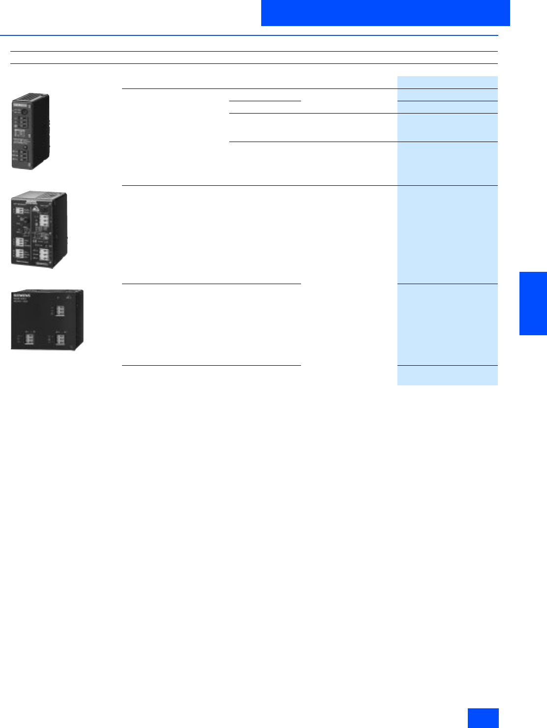
Siemens IK PI · 2004 6/139
AS-Interface Power Supply Units
Power supply units IP20
6
■
Selection and Ordering data
Design
Order No.
AS-Interface IP20 power supply unit
Type Output current Rated input voltage
3RX9 307–0AA00
Single output 2.4 A 115/230 V AC
(selectable)
3RX9 307–0AA00
4O
3RX9 307–1AA00
3.3 A
(can be connected
in parallel)
230/400 V AC
(repositionable)
4FD5 213-0AA10-1A
7 A 120/230 V AC
6EP1 354-1AL01
3RX9 310–0AA00
Single output
with integrated earth-fault
detection
2.4 A 115/230 V AC
(selectable)
3RX9 310–0AA00
3RX9 305–1AA00
Dual output 4 A /4 A
3RX9 305–1AA00
Combi output
(1 x 24 V DC / 1 x 30 V DC) 5 A (24 V)
4 A (AS-i)
3RX9 306–1AA00
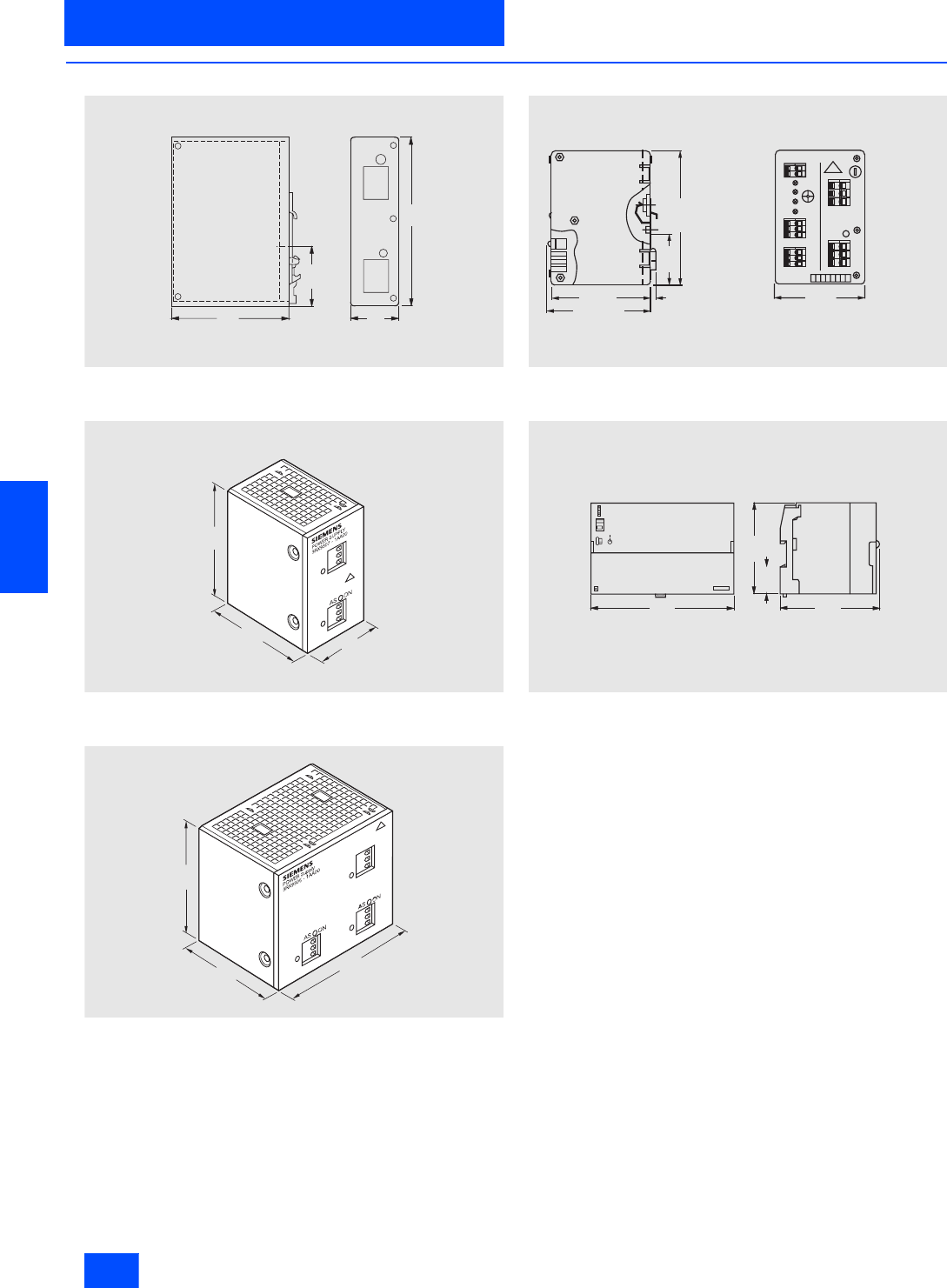
Siemens IK PI · 2004
6/140
AS-Interface Power Supply Units
Power supply units IP20
6
■
Dimensional drawings
3RX9 307-0AA00
3RX9 307-1AA00
3RX9 305-1AA00, 3RX9 306-1AA00
3RX9 310-0AA00
6EP1 354-1AL01
105
5 4 , 6
4 5
135
N S A 0 0 1 2 0
NSA00121
135
107
75
NSA00122
135
107
150
A B CD E F GH
1 0 5 + 1 9 0 + 1
N S A0_00123
5 4 , 6
7
1 3 5 + 1
m a x . 1 1 0
A S i
A S - i
__
_
S u i t a b l e f o r
m o u n t i n g o n t o
E N 5 0 0 2 2 - 3 5 x . . .
s t a n d a r d
m o u n t i n g r a i l
F u s e
2 5 0 V / 2 A
L E D d i s p l a y
N S A 0 0 1 2 4
S I T O P
S I E M E N S
p o w e r A S - I 6E P1 354-1A L01
O K
V O L T A G E
S E L E C T O R
135
2 0 0
3 6
125

Siemens IK PI · 2004 6/141
AS-Interface Power Supply Units
Power supply units IP65
6
■
Technical specifications
1) The counterpart is not included in the scope of supply (see accessories).
AS-Interface IP65 power supply unit
Rated input voltage 230 V AC Rated input voltage 24 V DC
3RX9 311-0AA00 6EP1 632-1AL01
Output current in A 2.4 2.4
Rated input voltage in V 230 AC 24 DC
Input
• Rated input voltage Ue rated in V 230 AC 24 DC
• Range selection Changeover contact (internal) --
• Input voltage range in V 195 to 253 20.4 to 28.8 DC
• Overvoltage resistance EN 61 000-4-1 35 V DC for max. 500 ms
• Mains buffering at Ie rated in ms > 20 > 10
• Mains frequency rated value I range
in Hz 50/60/47 to 63 --
• Input current rating Ie rated in A < 0.5 3.6
• Built-in input fuse in A T 2 (not accessible) T 6.3 (not accessible)
Output
• Stabilized floating DC voltage
acc. to AS-Interface specification Yes Yes
• Rated output voltage Ua rated in V 30 DC (AS-Interface) 30 DC (AS-Interface)
• Total tolerance 29.5 to 31.6 V DC 29.5 to 31.6 V DC
• Residual ripple in mVpp < 300 < 300
• Spikes in mVpp < 50 < 50
• Operational display Green LED Green LED
• Output current rating Ia rated in A 2.4 (power boost 2.8) 2.4
Efficiency/power loss
• Efficiency at Ua rated, Ia rated in % Approx. 85 > 81
• Power loss at Ua rated, Ia rated in W Approx. 10 < 17
Protection and monitoring functions
• Output overvoltage protection No --
• Current limitation in A > 2.8 From approx. 2.9
• Short-circuit protection Yes Stabilized current approx. 2.9 A
Safety
• Primary/secondary isolation Yes (SELV to EN 60 950) Yes (SELV to EN 60 950)
• Safety class Class I to IEC 536 Class I to IEC 536
• Degree of protection IP65 IP65
• Approvals CE, UL, CSA (in preparation) CE, UL, ship building
EMC
• Emitted interference EN 50 081-1 EN 50 081-1, EN 55 022 Cl. B
• Noise immunity EN 50 082-2 EN 50 082-2
Operational data
• Ambient temperature range in °C -45 to +55 -25 to +55
• Transport and storage
temperature range in °C -45 to +60 -25 to +85
• Humidity class Max. 80% rel. humidity F to DIN 40 040
Mechanical data
• Input connection Amphenol device socket Circular connector 0.5 to 2.5 mm21)
• Output connection AS-i + AS-i+/AS-i: via yellow AS-Interface cable 500 mm 3-wire conductor AWG 14
• Output connection AS-i - FK line adapter 500 mm 3-wire conductor AWG 14
• Output connection Ground -- 500 mm 3-wire conductor AWG 14
• Dimensions (W x H x D) in mm 105 155 117 224 80 57
• Mounting Mounting onto standard rails
DIN EN 50 022-35 x 7.5 Wall mounting
Special function -- --
Accessories -- 6-pole connector for input voltage (6ES5 760-2CA11)
and AS-Interface coupling module PG
(3RG9 220-0AA00) must be ordered separately
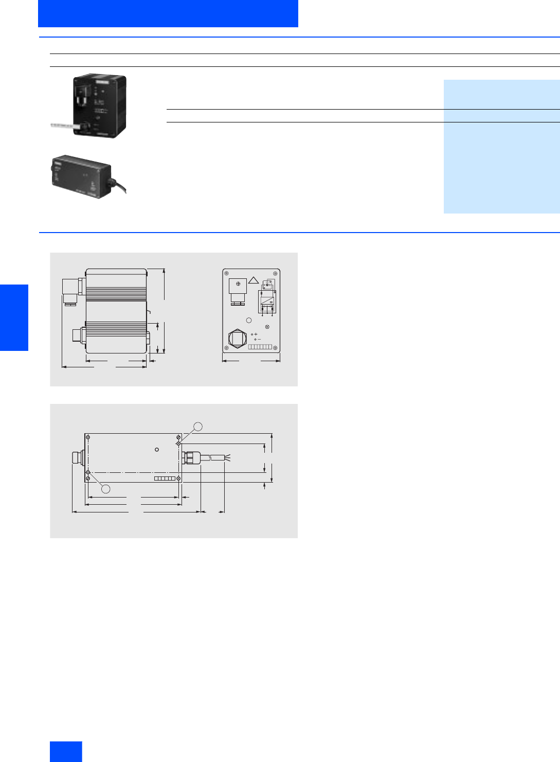
Siemens IK PI · 2004
6/142
AS-Interface Power Supply Units
Power supply units IP65
6
■
Selection and Ordering data
■
Dimensional drawings
3RX9 311-0AA00
6EP1 632-1AL01
Design
Order No.
3RX9 311–0AA00
6EP1 632–1AL01
AS-Interface power supply unit IP65
Typ e Output current
in A
Rated input
voltage
in V
Single output 2.4 230 AC
3RX9 311-0AA00
Single output 24 DC
6EP1 632-1AL01
A B CD E F GH
1 0 5 + 1
N S A 0 _ 0 0 1 1 7
1 1 0 + 1
5 4 , 6
7
1 4 8 + 2
1 4 5 + 1
A S i
A S - I n t e r f a c e
P o w e r o n A S i -
A S i +
~
A S - I n t e r f a c e
c o n n e c t i o n
M a i n s c o n n e c t i o n
S u i t a b l e f o r
m o u n t i n g o n t o
E N 5 0 0 2 2 - 3 5 x . . .
s t a n d a r d
m o u n t i n g r a i l
1 2 3 4 5 6
N S A 0 _ 0 0 1 1 8
1 P E
2 P 2 4
3 M 2 4
I N P U T
2 4 V / 4 , 2 A
P 3 0
M 3 0
O U T P U T
3 0 V / 2 , 8 A
6EP 1632-1A L01
1 6 3
1 7 5
6
2 2 4 5 0 0
5 2
8 0
1 4
P 3 0
M 3 0
R D
B U
B K
1
1
s h i e l d s h i e l d
A S - I n t e r f a c e
p o w e r R U N
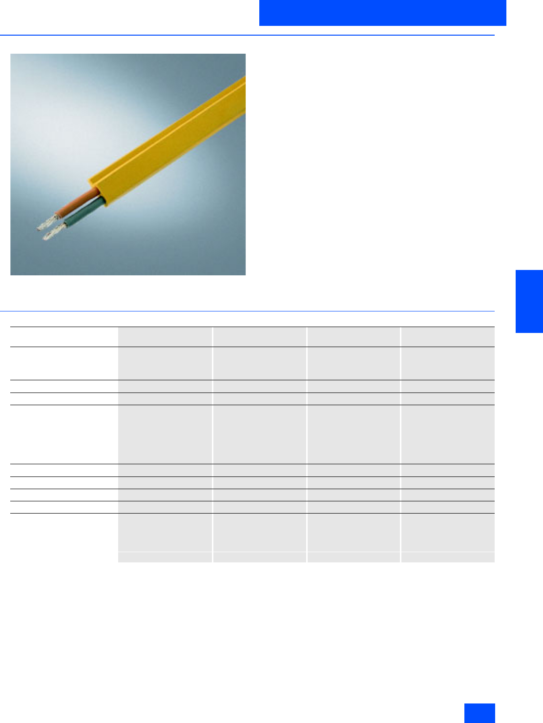
Siemens IK PI · 2004 6/143
AS-Interface
Transmission media
AS-Interface shaped cable
6
■
Overview
The actuator-sensor interface, the networking system for the low-
est field level, is characterized by easy assembly and installa-
tion. A new connection technique has been specially developed
for the AS-Interface.
The network stations are interconnected via the the AS-Interface
cable. This two-core cable has a trapezoidal profile which pre-
vents polarity reversal.
Connection is made with the cable using the insulation penetra-
tion technique. Blade contacts penetrate the AS-Interface
shaped cable and make reliable contact with the two cores.
Cutting and stripping of cores is not necessary. This technique
allows AS-Interface stations (e.g. I/O modules, intelligent de-
vices) to be connected in the shortest possible time. Devices
can also be replaced in an instant.
The AS-Interface cable is offered in various materials (rubber,
TPE, PUR) to suit applications in a wide range of environmental
conditions (e.g. in an atmosphere saturated with oil particles).
It is also possible to use a round cable for special applications.
In the case of AS-Interface, data and a 24 V DC auxiliary supply
voltage can be connected for the sensors (e.g. BERO proximity
switches) and actuators (e.g. LEDs) via the yellow AS-Interface
cable.
For 24 V DC actuators (e.g. solenoid valves) that have a high
current requirement or that are integrated into EMERGENCY
STOP circuits, the black AS-Interface cable must be used.
■
Technical specifications
EPDM
(rubber)
TPE
(special PVC compound)
TPE special version
acc. to UL Class 2
PUR
(Polyurethane)
Operating temperature range
• Stationary in °C -40 to +85 -40 to +105 -30 to + 90 -50 to +90
• Moving in °C -25 to +85 -30 to +105 -20 to + 90 -50 to +90
Color of cores Brown, blue Brown, blue Brown, blue Brown, blue
Flexibility Very Good Good Good Good
Behavior in fire flammable flame-retardant acc. to
IEC 60332-1
VDE 0482 T. 265-2-1
UL 1581 sec. 1061 cable
flame
UL 1581 sec. 1060 CSA
FT1
flame-retardant acc. to
IEC 60332-1
VDE 0482 T. 265-2-1
UL 1581 sec. 1061 cable
flame
UL 1685 CSA FT4
flame-retardant acc. to
IEC 60332-1
VDE 0482 T. 265-2-1
Halogen-free (PVC-free) Yes No No Yes
Silicone emission free Yes Yes Yes Yes
Ozone and weather resistant Conditionally resisting Resisting Resisting Resisting
Oil resistance Conditionally resisting Resisting Resisting Resisting
Smallest permissible bending
radius acc. to DIN VDE 0298,
Part 300, in mm
• Fixed in place 12 12 12 12
• Flexible 24 24 24 24
$6,QWHUIDFH
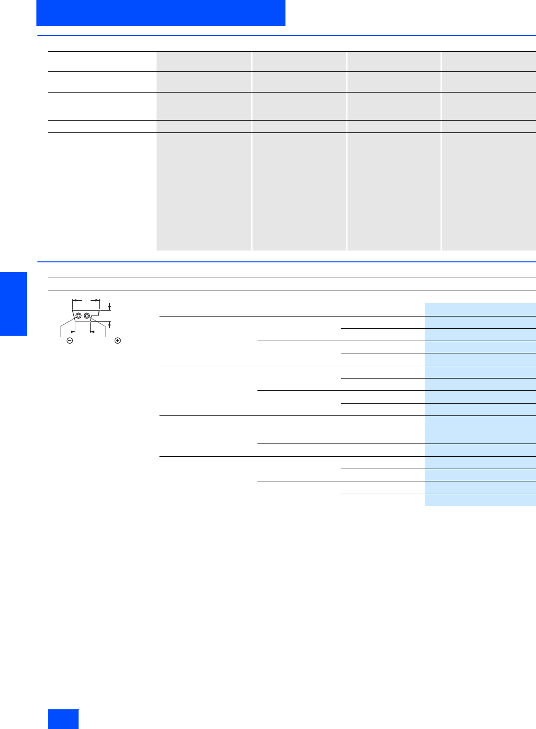
Siemens IK PI · 2004
6/144
AS-Interface
AS-Interface shaped cable
Transmission media
6
■
Technical specifications (continued)
■
Selection and Ordering data
1) Notes about the trailing capability of the AS-i cable with a PUR outer casing:
To determine the trailing capability, the AS-i cable was tested in "IGUS trailing chains of Types 10.2.048 and 20.2.55.
The trailing chain was fitted with 3 AS-i cables and various different round cables for this purpose.
After 3 million bending operations (vertical), there was no damage to the cores or litz wires or to the outer casing
(trailing chain equipped to 50% capacity).
EPDM
(rubber)
TPE
(special PVC compound)
TPE special version
acc. to UL Class 2
PUR
(Polyurethane)
Bending response to DIN VDE
0472, Part 603 No break after 30,000
movements to and fro No break after 30,000
movements to and fro No break after 30,000
movements to and fro No break after 30,000
movements to and fro
UL approval No UL 758 AWM UL 758 AWM
UL 13 Class 2
UL 444 CMG
No
CSA approval No C22.2 No.210.2 AWM C22.2 No. 214-02 No
Certificate "Überwachtes
Gutachten ÜG" (by VDE) No No No VDE reg. No. 9971
300 V/500 V
Stationary: -40 to +70 °C
Transport: -25 to +70 °C
Moving: -15 to +70 °C
Approved for marine and
offshore applications
up to 300 V/500 V:
Germanischer Lloyd
Lloyds Register of
Shipping
ABS Europe LTD
Bureau Veritas
Det Norske Veritas
Design
Order No.
AS-Interface shaped cable
Material Color Quantity
Rubber Yellow (AS-Interface) 100 m roller
3RX9 010-0AA00
1 km drum
3RX9 012-0AA00
Black (24 V DC) 100 m roller
3RX9 020-0AA00
1 km drum
3RX9 022-0AA00
TPE Yellow (AS-Interface) 100 m roller
3RX9 013-0AA00
1 km drum
3RX9 014-0AA00
Black (24 V DC) 100 m roller
3RX9 023-0AA00
1 km drum
3RX9 024-0AA00
TPE
Special design according to
UL Class2
Yellow (AS-Interface) 100 m roller
3RX9 017-0AA00
Black (24 V DC) 100 m roller
3RX9 027-0AA00
PUR 1) Yellow (AS-Interface) 100 m roller
3RX9 015-0AA00
1 km drum
3RX9 016-0AA00
Black (24 V DC) 100 m roller
3RX9 025-0AA00
1 km drum
3RX9 026-0AA00
b l a u
N S A 0 _ 0 0 1 2 5 a
1 0
4
6 , 5
A S - i A S - i
b r a u n
brownblue
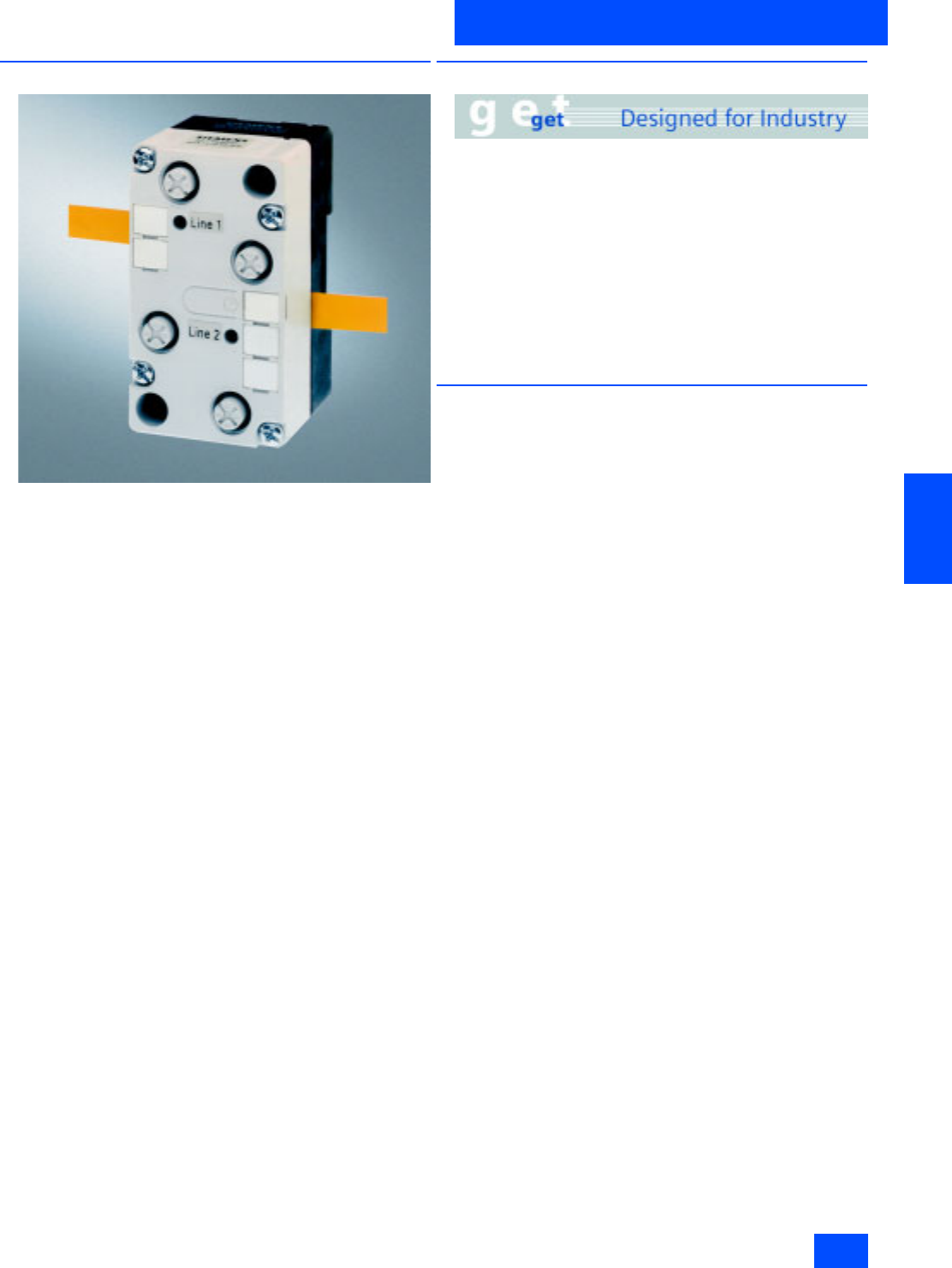
Siemens IK PI · 2004 6/145
AS-Interface
System components and accessories
Repeater/Extender
6
■
Overview
• Repeaters for extending the AS-Interface cable by 100 m
(max. 300 m possible)
• Repeaters can be cascaded
• Extenders for extending the distance (max. 100 m) between
the master and the AS-Interface segment
• Simple assembly technique
• IP67 module housing
■
Benefits
Repeaters
• Expansion of the range of applications and greater freedom in
plant design by extending the AS-Interface segment
• Reduction of standstill or service times in the event of a fault
with separate display of the correct AS-Interface voltage for
each end
Extenders
• Expansion of the range of applications and greater freedom in
plant design by extending the AS-Interface segment
• When the extender is used, the master can be located at a
distance of up to 100 m and a power supply is not required at
the master end.
■
Application
The repeater is used to extend the AS-Interface segment by
100 m.
The extender is used to extend the distance between the master
and the AS-Interface segment with the AS-Interface slaves to a
max. 100 m. A considerably greater cable length than 300 m
can be achieved when the repeaters are connected in parallel.
The maximum extension range is 500 m.
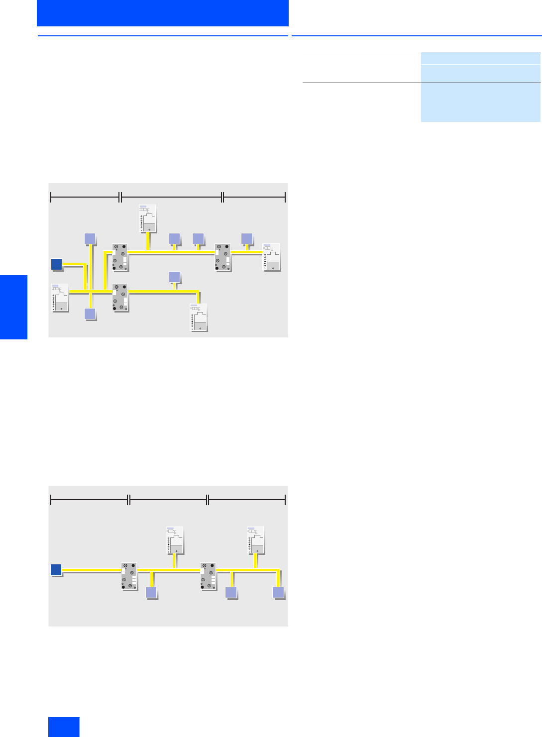
Siemens IK PI · 2004
6/146
AS-Interface
Repeater/Extender
System components and accessories
6
■
Design
Repeaters
• Slaves can be used on both sides of the repeater.
• Both sides require an AS-Interface power supply.
• Electrical isolation of the two AS-Interface lines.
Separate display of correct AS-Interface voltage for each side.
• Max. two repeaters may be used in series (max. cable length
300 m).
• Parallel connection of several repeaters is possible
(star configuration possible).
• Installed in user module housing with FK-E coupling module as
bottom part.
Repeater connection
Extenders
• Master can be placed at a distance of up to 100 m from the
AS-Interface segment itself.
• Slaves can be used only on side turned away from master.
• AS-Interface power supply only required on side turned away
from master.
• No electrical isolation of the two AS-Interface shaped cable
strands.
• Indication of correct AS-Interface voltage.
• Installed in user module housing with FK-E coupling module as
bottom part.
Extender connection
■
Ordering data Order No.
Power
section
Repeater
100 m 100 m 100 m
Repeater
Power section
Power section
Power
section
Repeater
M
SSS S
S
S
G_IK10_XX_20011
No slaves
Extender
100 m 100 m 100 m
Power section
SS
Repeater
S
Power section
M
G_IK10_XX_20012
Repeater for AS-Interface
6GK1 210-0SA00
For extending the cable run incor-
porating FK-E coupling module
Extender for AS-Interface
6GK1 210-1SA00
For installation of the master at a
distance incorporating FK-E cou-
pling module
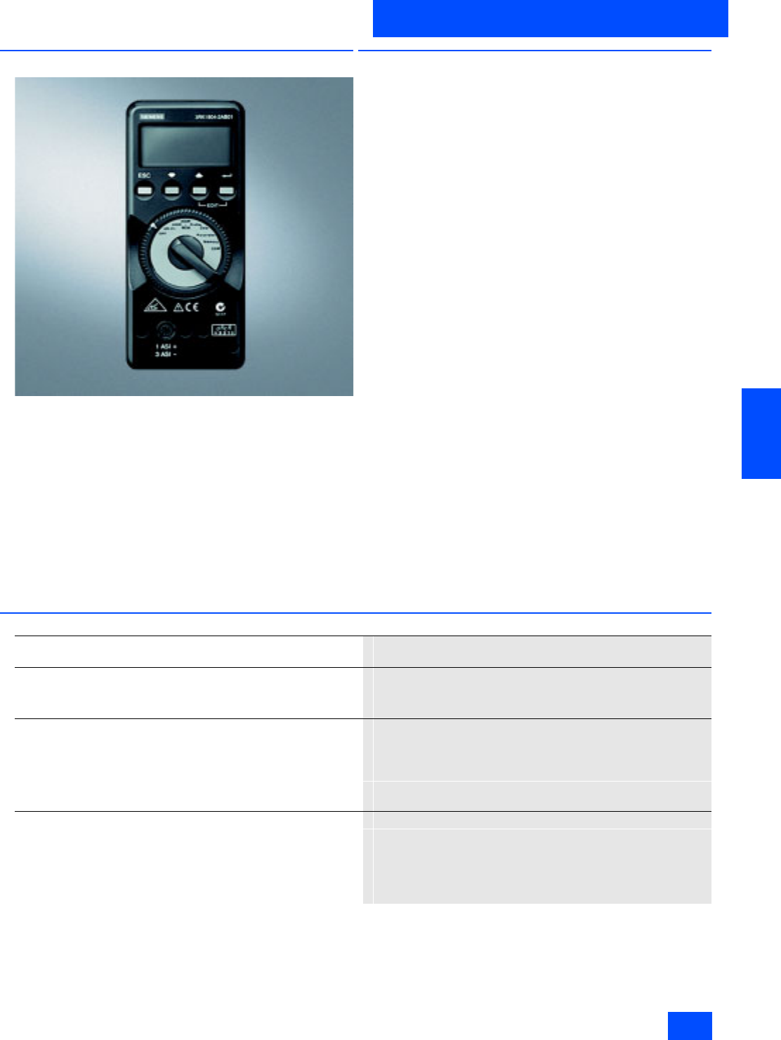
Siemens IK PI · 2004 6/147
AS-Interface
System components and accessories
Addressing units
6
■
Overview
Before data transfer can take place with the master, addresses
must be assigned to all stations before the AS-Interface network
is created. This can
• be performed offline using an addressing unit or
• online using a master of the AS-Interface system.
The addresses themselves are the values 1 to 31 (or 1A to 31A
and 1B to 31B for the extended specification). A new slave that
has not yet been addressed has the address 0. It is recognized,
also by the master, as a new slave (not yet addressed) and is not
integrated in the normal communication in this state.
The addresses are assigned as required, i.e. it is of no conse-
quence whether the first slave has the address 21 or whether ad-
dress 1 is assigned to the first slave.
■
Function
• Reading out the slave addresses 0 to 31, A/B
• Reading out the I/O and ID-codes of the slaves
• Standard and expanded ID-code 1 and ID-code 2
• Standard and expanded addressing mode according to
AS-Interface Version 2.1
• Programming ID-code 1
• Function testing of slaves: Read inputs and wire outputs of dig-
ital or anlog slaves
• AS-Interface test: Measurement of voltage (measuring range
0 to 35 V) and current consumption (measuring range 0 to
100 mA) of the AS-Interface bus
• Storage: Complete plant configurations can be saved (profiles
of all slaves, also extension in accordance with AS-Interface
specification 2.1)
• Detection of complete system configurations
■
Technical specifications
AS-Interface addressing and diagnostic unit
3RK1 904-2AB01
Power supply The standard power supply is provided by 4 IEC LR6 (NEDA 15)
batteries and guarantees that at least 2,500 addressing operations
can be performed. To save the batteries, automatic switch-off takes
place approx. 1 min. after the last button operation.
Ambient conditions
• Operating temperature range in °C 0 to +55
• Storage temperature range in °C -20 to +55 (without batteries)
• Relative humidity in % Max. 75, condensation must be prevented
• Height above sea level in m Up to 2,000
• Installation site Indoors only
Mechanical design
• Degree of protection
-Units IP50
- Connection sockets IP20
• Dimensions in mm 84 x 195 x 35
• Connection via M12 socket

Siemens IK PI · 2004
6/148
AS-Interface
Addressing units
System components and accessories
6
■
Selection and Ordering data
1) Not included in scope of supply of addressing unit 3RK1 904 0AB01.
2) Ordering is only possible via the following address:
Gossen-Metrawatt GmbH,
Thomas-Mann-Str. 16-20,
90471 Nuremberg, Germany
Tel.: +49 911/8602-111,
Fax: +49 911/8602-777,
e-mail: info@gmc-instruments.com
Design
Order No.
3RK1 904-2AB01
AS-Interface addressing and diagnostics unit
For active AS-Interface modules, intelligent sensors and actuators
According to AS-Interface Version 2.1
Including expanded addressing mode
Scope of supply:
• One addressing unit
• One operator’s guide (English, German, French, Italian, Spanish)
• One addressing cable (1.5 m, with jack plug)
3RK1 904-2AB01
Accessories
FK-E coupling module with integrated addressing socket 1)
For addressing application modules
3RK1 901-1MA00
Addressing cable with M12 female connector 1)
For addressing light curtains or K60R modules
1.5 m
3RX1 642
Addressing cable with jack plug 2)
1.5 m
Already included in scope of supply of the addressing unit 3RK1 904-2AB01
Z231A
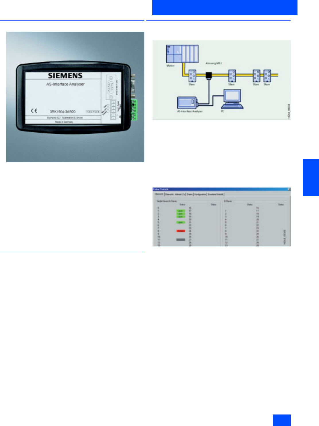
Siemens IK PI · 2004 6/149
AS-Interface
System components and accessories
Diagnostic units
6
■
Overview
The AS-Interface Analyzer is used to test AS-Interface networks.
Troubleshooting is made systematic, and permanent monitoring
is made easier.
Faults during installation, e.g. loose contacts or EMC problems
with extreme loads, can be detected by this analyzer.
The easily used software permits checking of the quality of com-
plete networks without having detailed technical knowledge of
the AS-Interface. The AS-Interface Analyzer additionally permits
documentation for commissioning and implemented services
through the simple generation of test reports for the recordings
made.
Detailed diagnostics is made possible for advanced
AS-Interface users by means of trigger functions.
■
Benefits
• Simple and convenient operation permits diagnostics of
AS-Interface networks without specialists.
• Fast troubleshooting is made possible by the intuitive display
in statistics mode.
• Test reports provide proof of the state and quality of the instal-
lation for servicing and approval.
• Reports facilitate remote diagnostics by the technical assis-
tance department.
• Advanced trigger functions permit exact analysis.
• Process data can be monitored online.
■
Function
Connection
As a passive station, the AS-Interface Analyzer listens to the
communication on the AS-Interface network. At the same time,
the analyzer is powered from the AS-Interface cable.
This bus monitor interprets the physical signals, and records the
communication.
The obtained data are transferred to a PC (usually a notebook)
via an RS232 interface, and evaluated there using the supplied
diagnostics software.
Online statistics
This mode provides a fast overview of the existing AS-Interface
system. The error rates per slave are displayed in a traffic signal
function (green, yellow, red).
The slave configuration and the currently transmitted data are
displayed in a clear manner.
The expanded statistics provides information on the numerical
data of the transmitted telegrams.
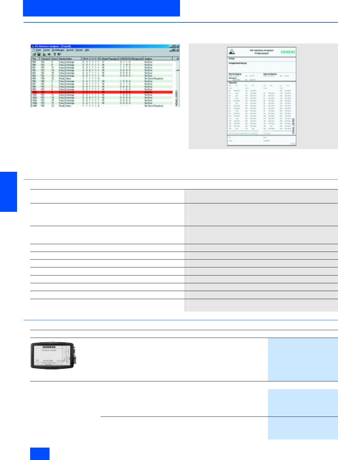
Siemens IK PI · 2004
6/150
AS-Interface
Diagnostic units
System components and accessories
6
■
Function (continued)
Trace modus
The telegram display in the style of a classical bus monitor is in-
dispensable for complex troubleshooting. Comprehensive trig-
ger functions as well as recording and viewing filters are avail-
able here.
The mode is rounded off by external trigger inputs and trigger
outputs to permit even the most difficult faults to be found.
Test report
The recorded data of the online statistics can be simply output
and documented in a test report. This provides proof of the state
of the installation for approvals or for servicing.
■
Technical specifications
■
Selection and Ordering data
AS-Interface Analyser
3RK1 904-3AB00
Interfaces AS-Interface
RS 232 for connection to the PC
Trigger input (24 V)
Trigger output (TTL)
Displays / LEDs Power supply OK (Power)
RS 232 interface in use
Test mode
Statistics mode Telegram memory 256,000 AS-Interface telegrams
Rated operating current in mA Approx. 70 from AS-Interface
Rated insulation voltage in V > 500
EMC According to EN50081-2, EN61000-6-2
Ambient temperature in °C 0 to +55
Storage temperature in °C -25 to +70
Requirements IBM-compatible PC, 80486 or better
Operating system Windows 95/98, Windows ME, Windows 2000,
Windows XP, Windows NT
Design
Order No.
AS-Interface Analyzer New
For testing actuator/sensor interface systems
For servicing in installations and networks with AS-Interface systems
Scope of delivery:
• One AS-Interface Analyzer
• One RS 232 cable for connection to the PC
• Diagnostics software (CD-ROM)
3RK1 904-3AB00
Accessories
AS-Interface M12 branch
Transition from AS-Interface shaped cable to standard round cable
Insulation piercing method for connection of AS-Interface cable
M12 socket for connection of standard round cable
IP67 degree of protection
3RX9 801-0AA00
M12 cable plug
Cable: PUR
Length: 5 m
Color: black
3RX1 672
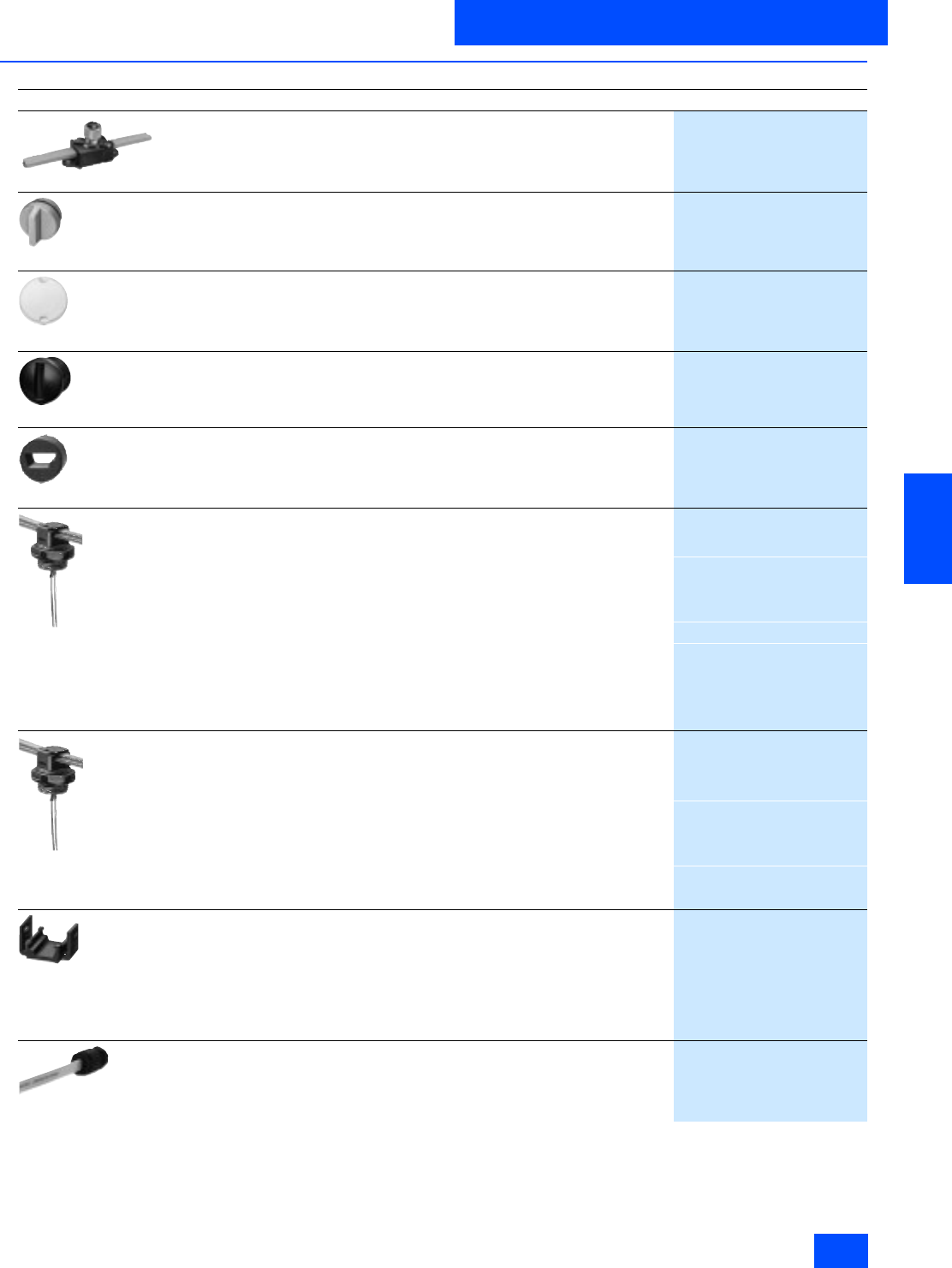
Siemens IK PI · 2004 6/151
AS-Interface
System components and accessories
Miscellaneous accessories
6
■
Selection and Ordering data
Design
Order No.
3RX9 801-0AA00
AS-Interface M12 branch
Transition from AS-Interface shaped cable to standard round cable
Insulation piercing method for connection of AS-Interface cable
M12 socket for connection of standard round cable
IP67 degree of protection
3RX9 801-0AA00
3RK1 901-1KA00
AS-Interface M12 sealing caps
For spare M12 sockets
(one packing contains ten sealing caps)
3RK1 901-1KA00
3RK1 901-1KA01
AS-Interface M12 sealing caps, protected against manipulation
For spare M12 sockets
(one packing contains ten sealing caps)
3RK1 901-1KA01
3RK1 901-1PN00
AS-Interface M8 sealing caps
For spare M8 sockets
(one packing contains ten sealing caps)
3RK1 901-1PN00
3RX9 805-0AA00
AS-Interface Pg 11 seal
For AS-Interface shaped cable
For inserting in Pg 11 cable glands
(one packing contains ten seals)
3RX9 805-0AA00
3RX9 806-0AA00
Cable adapter for flat cable/Pg
connection of AS-Interface cable to Pg cable glands
with insulation piercing method
• Continues via standard cable
- For Pg 9 screwed gland
3RX9 808-0AA00
- For Pg 11 screwed gland
3RX9 806-0AA00
- For Pg 13.5 screwed gland
3RX9 807-0AA00
• Continues via pins
- For Pg 9 screwed gland
3RX9 818-0AA00
- For Pg 11 screwed gland
3RX9 816-0AA00
- For Pg 13.5 screwed gland
3RX9 817-0AA00
3RK1 901-3QM00
Cable adapter for flat cable
Connection of AS-Interface cable to metric cable gland
with insulation piercing method
• Continues via standard cable
- For M16 cable gland
3RK1 901-3QM00
- For M20 cable gland
3RK1 901-3QM10
• Continues via pins
- For M16 cable gland
3RK1 901-3QM01
- For M20 cable gland
3RK1 901-3QM11
3RK1 901-3QA00
Cable clip for cable adapter
compatible to
3RX9 806-0AA00
3RX9 807-0AA00
3RX9 808-0AA00
3RX9 816-0AA00
3RX9 817-0AA00
3RX9 818-0AA00
(one packing contains ten cable clips)
3RK1 901-3QA00
3RK1 901-1MN00
Cable end piece
For sealing open cable ends (of the AS-Interface shaped cable) in IP67
(one packing contains ten cable end pieces)
3RK1 901-1MN00
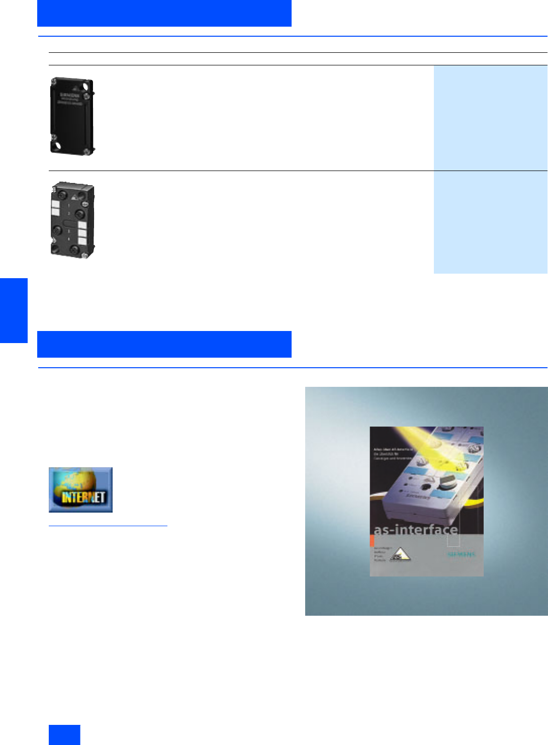
Siemens IK PI · 2004
6/152
AS-Interface
6
■
Selection and Ordering data (continued)
■
Overview
You can request the brochure About AS-Interface – An Overview
for Beginners and Users” free of charge in English and in
German
• by faxing to Fax. No. +49 911 978-33 21 supplying the refe-
rence code CD/Z 735 and your address
or on the Internet under the heading Documentation:
Additional information is available in the Internet under:
http://www.siemens.de/as-interface
Design
Order No.
3RX9 800-0AA00
AS-Interface cover
For FK and Pg coupling modules
EMS (electromechanical interface)
3RX9 800-0AA00
3RG9 001-0AD00
4-way distributor
Passive without LED
3RG9 001-0AD00
Brochures
Documentation
Miscellaneous accessories
System components and accessories
