Siemens Sitrans Fus1010 Nema 4X Ip 65 Clamp On Multi Function Flowmeter Users Manual FUS 1010NFM 3J Field
SITRANS FUS1010 NEMA-4X IP 65 to the manual 0852b8df-f344-44cf-b67c-74ce79e8f884
2015-02-05
: Siemens Siemens-Sitrans-Fus1010-Nema-4X-Ip-65-Clamp-On-Multi-Function-Flowmeter-Users-Manual-410291 siemens-sitrans-fus1010-nema-4x-ip-65-clamp-on-multi-function-flowmeter-users-manual-410291 siemens pdf
Open the PDF directly: View PDF ![]() .
.
Page Count: 232 [warning: Documents this large are best viewed by clicking the View PDF Link!]
- Sitrans FUS 1010 NEMA
- Addendum 1010FMA-4 - Wet Flow Calibration Procedure
- Addendum 1010FMA-14 - Expanded I/O Option
- Table of Contents
- Section 1 - Getting Started
- Section 2 - Installation Menu
- Section 3 - Hardware Installation Guide
- Section 4 - Meter Facilities Menu and Graphic Display Screen
- Section 5 - Application Notes
- Section 6 - Operating System 1010 with Flow Tubes
- Section 7 - System 1010 Reflexor Flowmeter
- Appendix A - Couplant Installation Instructions (if applicable)
- Appendix B - Site Setup Considerations for 1010/1020 Blind Systems
- Appendix C - Engineering Drawings
- Index
- Pipe Table
sitrans
Hier steht die HeadlineHier steht die Headline
+/-
=
CTRL ALT
789
456
321
0.
_
+
MENU
HELP
DATA
LOG
*
/
F1 F2 F3 F3
SITRANS FUS
CLR ENTER
Field Manual SITRANS FUS1010 NEMA-4X/ IP 65 Clamp-On Multi-Function Flowmeter
1010NFM-3J
Siemens Energy & Automation’s Standard Warranty
This warranty applies to flow metering and leak detection systems.
SIEMENS ENERGY & AUTOMATION CORPORATION (the Company) warrants to the original
purchaser of this equipment as presented in Section 1 of Siemens Energy & Automation, Inc.
Standard Terms and Conditions of Sale (10/1/2004).
To obtain repair or replacement within the terms of this Warranty, a Return Merchandise Authorization
number (RMA) must be obtained from Technical Service by calling (631) 231-3600 prior to shipment.
This RMA number must appear prominently on the outside of all returned packages. Returned
merchandise must include packing slip with specification of defect(s) and be shipped freight prepaid,
directly to Siemens Energy & Automation Corporation, 155 Plant Avenue, Hauppauge, NY 11788.
Equipment or material returned for Certification, Validation, Repair, or Replacement may result in the
loss of memorized pipe site date in equipment computer memory. Siemens Energy & Automation can
save and then restore this data for some NEMA type systems and all Portable systems, if requested at
the time of equipment return. A fee may be imposed for this service.
This Warranty does not extend to costs incurred for removal or reinstallation of the equipment, or to
damage to equipment, accessories or components caused by such removal or reinstallation.
This Warranty does not apply to any equipment or part thereof, which in the opinion of the Company
has been damaged through alteration, improper installation, mishandling, misuse, neglect, lightning
strike, or other accidents. THE EXTENT OF THE COMPANY’S LIABILITY UNDER THIS WARRANTY
IS LIMITED TO THE REPAIR OR REPLACEMENT PROVIDED ABOVE AND, IN NO EVENT, SHALL
THE COMPANY’S LIABILITY EXCEED THE PURCHASE PRICE PAID BY PURCHASER FOR THE
PRODUCT.
This Warranty is in lieu of all other express warranties or liabilities. ANY IMPLIED WARRANTIES,
INCLUDING ANY IMPLIED WARRANTY OF MERCHANTABILITY OR FITNESS FOR USE ARE
HEREBY EXCLUDED. IN NO CASE SHALL THE COMPANY BE LIABLE FOR ANY CONSEQUENTIAL
OR INCIDENTAL DAMAGES FOR BREACH OF THIS OR ANY OTHER WARRANTY, EXPRESS OR
IMPLIED, WHATSOEVER. No person or representative is authorized to assume for the Company
any liability other than expressed herein in connection with the sale of this equipment.

FOR TECHNICAL ASSISTANCE: FOR GENERAL INFORMATION:
Call: (800) 275-8480 Website: www.controlotron.com
(631) 231-3600 E-mail: info.ultrasonicflow@siemens.com
Fax: (631) 231-3334 Or: sales.ultrasonicflow@siemens.com
E-mail: TSG.ultrasonicflow@siemens.com
Field Manual 1010NFM-3J
August 2006
For use with Operating System
Software Version 3.01.05B or later
SITRANS FUS 1010N
NEMA-4X CLAMP-ON
MULTI-FUNCTION FLOWMETER
This equipment contains components that are
susceptible to electrostatic discharge (ESD).
Please observe ESD control measures during
the handling and connection process.
Printed August 2006
Prepared By Date
Engineering Date
FIELD MANUAL
Copyright©2006 Siemens Energy & Automation, Inc. All Rights Reserved Made in the USA
IMPORTANT NOTICE
Controlotron is now part of:
Siemens Energy & Automation, Inc.
Process Instrumentation Business Unit (PI BU)
CoC Ultrasonic Flow

Manual Changes
NOTE: For the latest updates and revisions to this field manual go to
www.controlotron.com/downloads.htm and check the Product Manual listing.

MANUAL
ADDENDUM
SETUP PROCEDURE FOR
WET-FLOW CALIBRATED
1010 SYSTEMS
System 1010 Uniflow
Portable & NEMA
Flowmeter Systems
Manual Addendum
July 2002
1010FMA-4
FOR TECHNICAL ASSISTANCE: FOR GENERAL INFORMATION:
Call: (800) 275-8480 Website: www.controlotron.com
(631) 231-3600 E-mail: info.ultrasonicflow@siemens.com
Fax: (631) 231-3334 Or: sales.ultrasonicflow@siemens.com
E-mail: TSG.ultrasonicflow@siemens.com
Copyright©2006 Siemens Energy & Automation, Inc. All Rights Reserved Made in the USA

Manual Addendum 1010FMA-4
July 2002
SETUP PROCEDURE FOR “WET-FLOW CALIBRATED” 1010 SYSTEM
1. INTRODUCTION
When the system 1010 is wet-flow calibrated, the flow computer stores the installation param-
eters in its storage memory. Each flow calibration is assigned a unique site name. Usually, the
site name corresponds to the pipe size. For example, a 3-inch carbon steel, schedule 40 pipe
would be given the name “3CS40.”
The flow calibration report issued with each wet-flow calibration, includes a flow calibration
“Diagnostic Data Sheet.” This data sheet lists the site name and other necessary information
(such as transducer serial number and spacing information), for setting-up the flowmeter. A
wet-flow calibration applies to a specific flowmeter and set of transducers; identified by serial
numbers on the diagnostic data sheet.
NOTE: In order for the flow calibration to be valid, the flow computer and transducers
being used must have the same serial numbers as those listed for the site on
the Calibration Diagnostic Data Sheet.
2. SETUP PROCEDURE
2.1 Transducer Installation
2.1.1 Refer to the diagnostic data sheet to find the mounting mode (Direct or Reflect) used
during the wet-flow calibration. Review the transducer installation guidelines in your 1010
field manual.
2.1.2 Refer to the diagnostic data sheet for the transducer spacing index utilized during the
flow calibration. Using the mounting configuration employed during the flow calibration,
install the transducers on the pipe at the above noted spacing positions in accordance
with the instructions provided on the transducer installation drawings.
2.1.3 Attach the transducer cables noting that the cable marked “UP” attaches to the trans-
ducer closest to the source of flow.
NOTE: Before proceeding further, ensure that the pipe is full of liquid. It is not impor-
tant at this point that it be flowing.
1
Caution: DO NOT use the field manual installation procedure to startup a wet-flow
calibrated system. Doing so could void the calibration by corrupting es-
sential data. This addendum contains the only authorized instructions to
be used when commissioning a wet-flow calibrated 1010 system.

Manual Addendum 1010FMA-4
2.2 Flowmeter Setup
NOTE: The following instructions require the use of the keypad and the menu. The
installer should become familiar with their use before proceeding further.
2.2.1 Switch the flowmeter on. Press the <MENU> key.
2.2.2 On multi-channel flowmeters, use the arrow keys to select [Dual Channel Flow] or
[Dual Beam Flow] depending on the mode utilized for the wet-flow calibration.
2.2.3 Use the arrow keys to select either [Clamp-on], [Flow Tube] or [Clamp-on Spool].
2.2.4 Select [Full Site Setup] and use the <Right Arrow> to select [Channel Setup]; then
select [Recall Site Setup].
2.2.5 Use the <Down Arrow> to scroll to the site name indicated on the Calibration Diagnos-
tic Data Sheet. Then press <ENT>.
2.2.6 The meter will perform a momentary “Makeup” routine that will take a few seconds and
then begin operation.
2.2.7 Refer to your 1010 field manual for instructions on setting zero flow.
NOTE: Setting zero flow must be performed each time the transducers are installed.
The zero adjustment has no effect on the wet-flow calibration data or the cali-
bration (Kc) factor.
2.2.8 Using the arrow keys, scroll to the Data Span/Set/Cal menu location. Verify that the [Kc]
(calibration) factor matches the value indicated on the diagnostic data sheet.
2.2.9 If you are measuring a liquid other than ambient water, select the [Liquid Class] menu
cell and <Down Arrow> from there to [Viscosity]. Enter the correct viscosity for the
liquid you will be monitoring.
2.2.10 Setup is now complete. Press the <MENU> key twice to view the flow rate display. DO
NOT utilize the [Save Site] command when it appears.
2.2.11 When measurements are completed, simply turn off the meter. DO NOT save the site.
This might contaminate the wet-flow calibration data already stored.
NOTE: Contact Siemens’ Technical Services Department if any flow calibration data is
accidentally removed or overwritten.
2July 2002

Manual Addendum 1010FMA-4
3. TRANSFER INSTALL FUNCTION
All 1010 flowmeter operating systems (version 3.00.20 and greater) include the installation facil-
ity called “Transfer Install.” This function permits the transducers to be repositioned while main-
taining all calibration parameters and operation established during the water calibration. The
Transfer Install function allows the transducers to be optimally positioned for a different fluid,
without the need for a new Initial Makeup procedure.
NOTE: Prior to performing Transfer Install make sure that the water calibration proce-
dure was performed and a saved active site exists.
3.1 Transfer Install Procedure
To initiate the Transfer Install function, proceed as follows:
3.1.1 In the Application Menu press the <Right Arrow> to select the [Liquid Class] menu cell.
Scroll and highlight [Estimated Vs m/s] from the option list.
3.1.2 Use the numeric keys to change the Estimated Vs to the Estimated Vs value of the
customer selected liquid.
3.1.3 To enter new Estimated Vs value press <ENT>.
3.1.4 Proceed to the Pick/Install Xdcr menu and select the same transducer, mounting mode
and spacing offset that was selected for the water calibration.
3.1.5 Re-space the transducers to the index position indicated by the flowmeter.
3.1.6 Scroll to the [Install Completed?] menu cell and select [Transfer Install] from the option
list.
NOTE: If [Transfer Install] does not appear in the option list then either the Estimated
Vs or the transducer size was improperly entered. In this case, recall the water
calibration site and start the procedure again at Step 3.1.1 above.
3.1.7 For MultiPath systems repeat Step 3.1.6 above for the remaining paths.
3.1.8 The flowmeter should now be operational at the new spacing location.
NOTE: Depending on the size of the pipeline, the change in the estimated sonic veloc-
ity (Vs) and the repositioning of transducers, the flowmeter may not operate out
of Fault even if the spool or pipe is filled with liquid. This can be expected when
performing a Transfer Install for liquified gases or for clamp-on natural gas flow-
meters.
3.2 Saving New Transfer Install Site
3.2.1 To save the Transfer Installed site, scroll to the Channel Setup menu and press the
<Right Arrow>. Press the <Right Arrow> again to select the [Save/Rename] menu cell.
3.2.2 Use the numeric keys to rename the Transfer Installed site with the same site name
used in Step 3.1.2 above, but with a “T” appended to the end of the site name (e.g.,
3CS40T).
3.2.3 Press <ENT> to store data.
July 2002
3

MANUAL
ADDENDUM
Manual Addendum
May 2002
1010FMA-14
SYSTEM 1010
EXPANDED I/O OPTION
(For Systems Equipped With 1010N-7 Modules)
FOR TECHNICAL ASSISTANCE: FOR GENERAL INFORMATION:
Call: (800) 275-8480 Website: www.controlotron.com
(631) 231-3600 E-mail:info.ultrasonicflow@siemens.com
Fax: (631) 231-3334 Or: sales.ultrasonicflow@siemens.com
E-mail: TSG.ultrasonicflow@siemens.com
Copyright©2006 Siemens Energy & Automation, Inc. All Rights Reserved Made in the USA

Manual Addendum 1010FMA-14
May 2002
1
EXPANDED I/O OPTION
(For Systems Equipped With 1010N-7 Modules)
INTRODUCTION
The 1010N-2 I/O Module and 1010N-7 Expanded I/O Module both provide current (Io1, Io2), voltage
(V01 and Vo2) and pulse rate (Pgen 1 and Pgen 2) analog outputs. The Expanded I/O Module Option
allows users to drive as many as four additional 4-20 mA loop-powered instrumentation outputs. The
following information is intended to be used with the I/O Data Control and Span Data sections and
Analog Output Trim Menu in the field manual.
The System 1010 flowmeter provides an Analog Output Setup menu (see below) that allows the user
to assign data functions for these output signals (refer to Analog Output Setup in the appropriate 1010
field manual). In addition, refer to Installation Drawings 1010N-2-7 and 1010N-7-7 in the field manual
appendices for additional connection information and terminal block numerical designators.
NOTE: All meters in the System 1010N and DN product family can accept the Expanded I/O
Module Option except 4-Channel meters.
EXPANDED I/O MODULE OPTION
The Expanded I/O Module Option provides expanded Io analog outputs. It is implemented through the
use of a 1010N-7 Expanded I/O Module occupying the same position as the 1010N-2 I/O Module. This
option allows users to drive up to four additional 4-20mA loop-powered instrumentation outputs. Note
that the meter menu does not indicate that these supplementary outputs are present and available.
The outputs, in addition to being loop-powered, are isolated from one another as well as the meter.
Expanded I/O Module Option Identification
To verify that your meter has the Expanded I/O Module Option installed check the following:
The designation A1 should be part of the flowmeter part number.
For example: 1010ENRE-T1A1KGS
Siemens Dual Path SITE1
Assign Data to Analog Outputs
I/O Data Control
Analog Out Setup
Relay Setup
Analog Input Setup
Use this menu to
assign data functions
to analog outputs.

Manual Addendum 1010FMA-14
2May 2002
1010N-2 I/O Module
The conventional 1010N-2 I/O module provides the following:
zTwo self-powered, isolated 4-20 mA current loops (signals Io1 and Io2) that are assignable and
spannable by the user to many flowmeter variables such as flow, sonic velocity, signal strength,
etc. These self-powered outputs also provide an industry-standard fault indication by dropping
to 2 mA if assigned to flow rate and under fault conditions. Note that these outputs, though
isolated from the system, are NOT isolated from each other.
zTwo 0-10 Vdc outputs (signals Vo1 and Vo2) that are also assignable and spannable by the
user as above. These are also self-powered, but are not isolated from the system.
zTwo 0-5000 Hz Pgen signals (Pgen1 and Pgen2) also assignable and spannable by the user.
These are TTL level pulses.
The 1010N/DN class of meters has a total of six analog outputs as indicated above. In addition (refer to
Installation Drawings 1010N-2-7 and 1010N-7-7):
zAlarms/Status/Totalizer pulses are generally presented as relay closures as either Mercury
Wetted Form 1A or Dry Reed Form C relays.
zAnalog inputs, when provided, are in the form of 4-20 mA non-isolated inputs.
zThe meter also has four non-isolated totalizer command lines providing Totalizer Clear and
Totalizer Hold (NoTot) functionality.
1010N-7 Expanded I/O Module Option
The Expanded I/O Module Option provides all of the above plus the following outputs:
zThe four signals that drive the pulse generator outputs (Pgen 1 and Pgen2) and voltage outputs
(Vo1 and Vo2) of the meter create four current outputs: Aux Io1, Aux Io2, Aux Io3 and Aux Io4
(see diagram on next page).
zBy spanning and assigning a system variable to 0-10 volt (Vo1 and Vo2) or 0-5000 Hz pulse
output (Pgen1 and Pgen2) the module simultaneously outputs these signals to the Expanded
I/O Module Option Aux outputs. For a 2-Channel meter the programming assignments are as
follows:
CHANNEL SIGNAL AUX Io METER MENU DISPLAY
CH1 Pgen1 Io1 Vo1
Vo1 Io3 Pgen1
CH2 Pgen2 Io2 Vo1
Vo2 Io4 Pgen1
TYPICAL 2-CHANNEL METER EXPANDED I/O OPTION CONNECTIONS
zNote that the four Aux Io outputs are externally powered.

Manual Addendum 1010FMA-14
3May 2002
NOTE: The method used to create auxiliary current loops makes it impractical to generate the
2 mA fault current produced by the primary 4-20 mA outputs of the meter.
NOTE: The 1010N-7 Expanded I/O Module auxiliary output signals (Aux Io1 - Aux Io4) geneated
from Pgen1, Pgen2, Vo1 and Vo2 are “mirrored” output currents. For example, if Vo1
is a 5 Vdc signal then Aux Io3 will be 12 mA.
EXPANDED I/O MODULE OPTION PROGRAMMING
The diagram below illustrates the Expanded I/O Module Option programming for a Single Channel
meter with a 1010N-7 Expanded I/O Module.
FLOW COMPUTER
INTERNAL
CONNECTIONS
Io1
Io1
Pgen1
Pgen2
Vo1
Vo2
Aux Io1
Aux Io2
Aux Io3
Aux Io4
OUTPUT
TERMINAL STRIP
z
z
z
z
```
`` `

1010NFM-3J Table Of Contents
Section 1
1. Getting Started................................................................................................ 1-1
1.1 Introduction ..................................................................................................... 1-1
1.2 Important Safety Considerations................................................................... 1-1
1.3 Flowmeter Installation Steps ......................................................................... 1-1
1.4 The Keypad Enable Switch ............................................................................ 1-2
Typical System Layout ............................................................................. 1-2
1.5 The 1010N Keypad .......................................................................................... 1-3
Keypad Function Chart ............................................................................ 1-3
1.6 Introduction To The 1010N Menu Screens .................................................. 1-3
Typical Installation Menu Screen .............................................................. 1-3
Explanation of the Callouts....................................................................... 1-4
1.7 How To Use The Installation Menu ............................................................... 1-4
1.7.1 Accessing And Leaving The Menu ................................................................ 1-5
1.7.2 How To Enter Data .......................................................................................... 1-5
Selecting Items from an Option List ......................................................... 1-6
Multiple Select Option Lists ...................................................................... 1-7
Entering Numeric Data............................................................................. 1-7
Entering Alphanumeric Data .................................................................... 1-8
1.7.3 The Meter Type Menu .................................................................................... 1-8
Dual Channel ........................................................................................... 1-9
Dual Path ................................................................................................. 1-9
Channel 1+2 and Channel 1-2 ................................................................. 1-9
1.7.4 Essential Information For Users of Multi-Channel 1010’s ........................ 1-10
Multi-Channel Meter Setup ..................................................................... 1-10
Arithmetic Operation .............................................................................. 1-10
Multi-Path Operation............................................................................... 1-10
Selecting a Meter Type ............................................................................1-11
Creating a New Site Setup ..................................................................... 1-12
Flowmeter Installation Flowchart............................................................ 1-14
1.8 Using FASTSTART Setup ............................................................................. 1-15
1.8.1 Choosing The Pipe Class/Size .................................................................... 1-15
1.8.2 Picking And Installing The Transducers ..................................................... 1-16
1.9 1010WX Clamp-On Liquid Flowmeters ........................................................ 1-19
Section 2
2. The 1010N Installation Menu ......................................................................... 2-1
2.1 The Channel Setup Menu .............................................................................. 2-2
Channel Setup Menu Structure ................................................................ 2-2
2.1.1 How To Recall A Site Setup ............................................................................ 2-2
2.1.2 How To Enable And Disable A Measurement Channel ................................ 2-3
2.1.3 How To Create/Name A Site Setup ................................................................ 2-4
2.1.4 How To Enable/Disable Site Security ........................................................... 2-4
2.1.5 How To Delete A Site Setup ........................................................................... 2-5
2.1.6 How To Save/Rename A Site Setup............................................................... 2-5
2.2 The Pipe Data Menu ....................................................................................... 2-6
The Pipe Data Menu Structure ................................................................. 2-7
2.2.1 How To Select A Pipe Class ........................................................................... 2-8
Sect./Page
TABLE OF CONTENTS
i

1010NFM-3J Table Of Contents
ii
2.2.2 How To Select A Pipe Size ............................................................................. 2-8
2.2.3 How To Enter The Pipe OD (in. or mm) ........................................................ 2-9
2.2.4 How To Select A Pipe Material ....................................................................... 2-9
2.2.5 How To Enter The Wall Thickness ................................................................ 2-9
2.2.6 Liner Material ................................................................................................ 2-10
2.2.7 Liner Thickness............................................................................................. 2-10
2.3 The Application Data Menu .......................................................................... 2-10
Application Data Menu Structure .............................................................2-11
2.3.1 How To Select A Liquid Class ...................................................................... 2-13
How to Edit the Estimated Vs (liquid sonic velocity)............................... 2-13
How to Edit the Viscosity (cS) Setting.................................................... 2-14
How to Edit the Density (SG) Setting ..................................................... 2-14
2.3.2 UniMass Table ............................................................................................... 2-14
Application Data Menu Explanations for UniMass Table ......................... 2-15
2.3.3 How To Select A Pipe Temperature Range ................................................ 2-18
2.3.4 Pipe Configuration ........................................................................................ 2-19
Pipe Configuration Menu Structure......................................................... 2-19
Additional Compensation Tables ............................................................ 2-20
2.4 The Pick/Install XDCR Menu........................................................................ 2-20
Pick/Install Xdcr Menu Structure............................................................. 2-22
2.4.1 How To Select A Transducer Model ............................................................ 2-22
2.4.2 How To Select A Transducer Size ............................................................... 2-23
2.4.3 How To Select A Transducer Mount Mode ................................................. 2-23
2.4.4 Reviewing The Spacing Method ................................................................. 2-24
2.4.5 How To Use The Spacing Offset ................................................................. 2-24
2.4.6 The Number Index Menu Cell...................................................................... 2-25
2.4.7 The Ltn Menu Cell ........................................................................................ 2-25
2.4.8 How To Use [Install Completed?]................................................................ 2-25
Force Transmit Procedure ..................................................................... 2-27
2.4.9 The Empty Pipe Set Menu............................................................................ 2-29
How to Use the Actual MTY Command .................................................. 2-29
How to Use the MTYmatic Command .................................................... 2-30
How to Use the Set Empty Command ................................................... 2-30
2.4.10 The Zero Flow Adjust Menu ......................................................................... 2-30
AutoZero ................................................................................................. 2-30
Actual Zero ............................................................................................. 2-31
ReversaMatic ......................................................................................... 2-31
ZeroMatic (definition) .............................................................................. 2-31
Using Actual Zero ................................................................................... 2-31
Using ReversaMatic ............................................................................... 2-32
ZeroMatic (optional function) .................................................................. 2-33
2.5 The Operation Adjust Menu ......................................................................... 2-34
Operation Adjust Menu Structure............................................................ 2-35
2.5.1 Damping Control ........................................................................................... 2-35
2.5.2 Deadband Control ......................................................................................... 2-35
2.5.3 Memory/Fault Set .......................................................................................... 2-36
Memory Delay (sec) ............................................................................... 2-36
2.5.4 Reflexor Zero/Fault Set Option (Reflexor Mode only) .............................. 2-36
2.6 The Flow/Total Units Menu .......................................................................... 2-37
POSFLOW ............................................................................................ 2-37
NEGFLOW............................................................................................. 2-37

1010NFM-3J Table Of Contents
iii
NETFLOW ............................................................................................. 2-37
Totalizer Controls ................................................................................... 2-37
The Flow/Total Units Menu Structure ...................................................... 2-38
2.6.1 Flow Volume Units ......................................................................................... 2-38
2.6.2 Flow Time Units ............................................................................................. 2-39
2.6.3 Flow Display Range....................................................................................... 2-40
2.6.4 Flow Display Scale ........................................................................................ 2-40
2.6.5 Total Volume Units ........................................................................................ 2-40
2.6.6 Totalizer Scale............................................................................................... 2-41
2.6.7 Total Resolution ............................................................................................ 2-41
2.6.8 Totalizer Mode .............................................................................................. 2-42
2.6.9 Batch/Sample Total ....................................................................................... 2-42
2.7 The Data Span/Set/Cal Menu....................................................................... 2-42
The Data Span/Set/Cal Menu Structure ................................................. 2-43
2.7.1 Span Data ....................................................................................................... 2-43
Max Flow ................................................................................................ 2-44
Min Flow ................................................................................................. 2-44
Max Vs m/s ............................................................................................ 2-45
Min Vs m/s ............................................................................................. 2-45
Max Vs m/s ............................................................................................ 2-45
Min Vs m/s ............................................................................................. 2-45
Max S.G. ................................................................................................. 2-45
Min S.G. .................................................................................................. 2-45
Max Viscosity cS .................................................................................... 2-45
Min Viscosity cS ..................................................................................... 2-45
Max Temperature ................................................................................... 2-45
Min Temperature .................................................................................... 2-45
2.7.2 Set Alarm Levels............................................................................................ 2-45
High Flow ............................................................................................... 2-46
Low Flow ................................................................................................ 2-46
High S.G. ................................................................................................ 2-46
Low S.G.................................................................................................. 2-46
High Viscosity cS ................................................................................... 2-46
Low Viscosity cS.................................................................................... 2-46
High Temperature ................................................................................... 2-46
Low Temperature ................................................................................... 2-46
Interface Vs (m/s) meters-per-second................................................... 2-47
Aeration % .............................................................................................. 2-47
Makeup Latch ......................................................................................... 2-47
2.7.3 Calibrate Flow Rate....................................................................................... 2-48
Kc Calibration......................................................................................... 2-48
MultiPoint Calibration .............................................................................. 2-48
2.8 The StripChart Setup Menu......................................................................... 2-50
The StripChart Setup Menu Structure .................................................... 2-50
2.8.1 Select Data..................................................................................................... 2-50
2.8.2 Data Display ................................................................................................... 2-51
2.8.3 Time Base ...................................................................................................... 2-51
2.8.4 StripChart Clear ............................................................................................ 2-52
2.9 The Datalogger Setup Menu ....................................................................... 2-52
The Datalogger Setup Menu Structure ................................................... 2-53

1010NFM-3J Table Of Contents
iv
2.9.1 Datalogger Mode........................................................................................... 2-54
2.9.2 Datalogger Data............................................................................................. 2-54
Alarm Letter Codes and Descriptions .................................................... 2-55
2.9.3 Log Time Interval .......................................................................................... 2-55
2.9.4 Datalogger Events ........................................................................................ 2-55
2.9.5 Display Datalogger ........................................................................................ 2-56
2.10 The I/O Data Control Menu .......................................................................... 2-57
The I/O Data Control Menu Structure ..................................................... 2-58
2.10.1 Analog Out Setup .......................................................................................... 2-58
System 1010 Analog Outputs ................................................................ 2-59
Analog Output Data Categories ............................................................. 2-59
Table to Determine Proper I/O installation Drawings.............................. 2-59
Assigning Io Output Functions ............................................................... 2-59
Assigning Vo Output Functions .............................................................. 2-60
Assigning Pgen Output Functions.......................................................... 2-60
Pulse Output Table (Pgen Wiring).......................................................... 2-60
2.10.2 Relay Setup.................................................................................................... 2-60
Assigning Relay 1 and 2 Functions ........................................................ 2-61
Relay Option List.................................................................................... 2-61
2.10.3 Analog Input Setup (optional function) ....................................................... 2-61
Setting Up the Analog Current Input ....................................................... 2-62
2.11 The Diagnostics Data Menu......................................................................... 2-62
Diagnostic Data Menu Structure ............................................................ 2-63
2.11.1 Main Diagnostics Screen ............................................................................. 2-64
Main Diagnostic Menu Description ......................................................... 2-64
2.11.2 Flow Data Menu ............................................................................................. 2-64
Flow Data Menu Items ........................................................................... 2-65
Vs m/s.................................................................................................... 2-65
HiFlow and LoFlow................................................................................. 2-66
AnCal ..................................................................................................... 2-66
2.11.3 The Application Info Menu .......................................................................... 2-67
Application Info Menu Items.................................................................... 2-67
2.11.4 The Liquid Data Menu .................................................................................. 2-67
Liquid Data Menu Items.......................................................................... 2-67
2.11.5 The Site Setup Data Menu ........................................................................... 2-68
Site Setup Menu Items ........................................................................... 2-68
Introduction to [HF] Menu Item................................................................ 2-69
Using the [HF] Menu Item ....................................................................... 2-69
“Manual” Adjustment Procedure ............................................................. 2-70
“Automatic” Adjustment Procedure ........................................................ 2-71
2.11.6 The Test Facilities Menu .............................................................................. 2-72
Test Facilities Commands ..................................................................... 2-72
Makeup ................................................................................................... 2-72
Detection Mode ...................................................................................... 2-73
The Test Facilities Graph Screen ........................................................... 2-73
Entering The Diagnostic Graph Screen ................................................. 2-74
Diagnostic Text Display .......................................................................... 2-74
Time Base Control ................................................................................. 2-74
Correlated Plot ....................................................................................... 2-74
Command Modes .................................................................................. 2-75
Digital Damping Control: (Hot Key 1 and 2) ................................... 2-75

1010NFM-3J Table Of Contents
v
Transit Time Adjustment: (Hot Key 3)............................................. 2-75
Zero Crossover Adjustment: (Hot Key 4) ....................................... 2-76
Envelope Threshold Adjustment: (Hot Key 5 & 6) .......................... 2-76
Signal Masking Function: (Hot Key 7) ............................................ 2-77
Description Of Graph Screen Text Display Parameters ........................ 2-77
Hot Key Summary.................................................................................. 2-77
2.11.7 Troubleshooting Tips ................................................................................... 2-78
Flow Computer Messages ..................................................................... 2-78
Using the “F4” Reset Sequence............................................................. 2-79
2.11.8 Troubleshooting With Transducer Test Blocks ......................................... 2-81
2.11.9 Using The 1012TB-1 And -2 Test Blocks .................................................... 2-81
2.11.10 Using The 996PSP Pipe Simulator .............................................................. 2-83
If a Pipe Simulator/Test-Block Test Fails ................................................ 2-84
2.12 Guide To A Smooth Installation.................................................................... 2-85
2.12.1 Checklist for 1010 Startup & Performance ................................................. 2-85
Programming ......................................................................................... 2-85
Installation/Transducer Mount Guidelines ............................................... 2-85
Startup.................................................................................................... 2-86
Diagnostic/Performance Verification ...................................................... 2-86
2.12.2 Optimization/Correction of Problems ......................................................... 2-86
Incorrect “Measured Vs”......................................................................... 2-86
Low Valc................................................................................................. 2-87
Detection Fault/Low Signal .................................................................... 2-87
High Vaer ................................................................................................ 2-87
Poor Signal............................................................................................. 2-88
“Official” Coupling Compound ................................................................ 2-88
“Alternative” Coupling Compound .......................................................... 2-88
Ideal Vsig Display ................................................................................... 2-89
Section 3
3. Hardware Installation Guide .......................................................................... 3-1
3.1 Preparing To Mount The Transducers ......................................................... 3-1
3.1.1 How To Identify 1011 Transducers and Mounting Hardware ...................... 3-1
3.1.2 Selecting A Location For Clamp-On Transducers ....................................... 3-1
3.1.3 Clamp-On Transducer Mounting Modes ..................................................... 3-2
3.1.4 Preparing The Pipe......................................................................................... 3-3
3.1.5 Reflect Mode - Mounting Frames And Spacer Bar ...................................... 3-4
3.1.6 Reflect Mode With Spacer Bar Only ............................................................. 3-5
3.1.7 Direct Mode-Mounting Frames, Spacer Bar & Spacing Guides ................ 3-7
3.1.8 Using 1012T Mounting Tracks ......................................................................3-11
Installing a 1012T Mounting Track in Reflect Mode.................................. 3-11
Installing a 1012T Mounting Track in Direct Mode .................................. 3-13
3.2 Mounting Temperature Sensors ................................................................. 3-15
3.2.1 Wiring Temperature Sensor To The Analog Input Module ....................... 3-16
3.2.2 1010N Supply And Return Connections...................................................... 3-17
3.2.3 Notes On 1010 Analog Input Modules ......................................................... 3-18
Single Channel Model............................................................................. 2-18
Dual Channel Model ............................................................................... 2-18
3.2.4 Clamp-On RTD Installation Notes ............................................................... 3-19
3.2.5 Paralleling RTD Inputs For Dual-Channel Energy Measurement. ............. 3-19

1010NFM-3J Table Of Contents
vi
Section 4
4. The Meter Facilities Menu And Graphic Display Screens .......................... 4-1
4.1 Preferred Units................................................................................................ 4-1
4.2 The Table Setups Menu ................................................................................. 4-2
4.2.1 Pipe Table ........................................................................................................ 4-2
Pipe Table Menu Structure ....................................................................... 4-2
4.2.2 Create/Edit Pipe .............................................................................................. 4-3
4.2.3 Delete Pipe ...................................................................................................... 4-4
4.3 Transducer Type Menu .................................................................................. 4-4
Transducer Type Menu Structure ............................................................. 4-5
4.4 The Datalogger Control Menu....................................................................... 4-6
4.4.1 Display Datalogger .......................................................................................... 4-6
4.4.2 Output Datalogger .......................................................................................... 4-7
4.4.3 Circular Memory .............................................................................................. 4-7
4.4.4 Est Log Time Left ............................................................................................ 4-8
4.4.5 Clear Datalogger ............................................................................................. 4-8
4.5 The Memory Control Menu ............................................................................ 4-8
Data Memory Left..................................................................................... 4-8
Memory Map............................................................................................. 4-8
Defragment .............................................................................................. 4-8
4.5.1 The Analog Output Trim Menu....................................................................... 4-9
4.5.2 Current Output Trim (Io1 & Io2) ..................................................................... 4-9
4.5.3 Voltage Output Trim (Vo1 & Vo2).................................................................... 4-9
4.5.4 Pgen Output Trim (Pgen 1 & Pgen 2).......................................................... 4-10
4.6 The RTD Calibrate Menu (optional) ............................................................ 4-10
RTD Calibrate Menu Structure ................................................................4-11
4.6.1 The RTD Calibrate by Data Entry .................................................................4-11
4.6.2 Ice Bath RTD Calibration...............................................................................4-11
4.7 The Clock Set Menu ..................................................................................... 4-12
4.7.1 Date ................................................................................................................ 4-12
4.7.2 Time ................................................................................................................ 4-12
4.8 RS-232 Setup ................................................................................................. 4-13
RS-232 Menu Structure.......................................................................... 4-13
4.8.1 Baud Rate ...................................................................................................... 4-13
4.8.2 Parity ............................................................................................................... 4-14
4.8.3 Data Bits ......................................................................................................... 4-14
4.8.4 Line Feed ....................................................................................................... 4-14
4.8.5 Network ID ..................................................................................................... 4-15
4.8.6 RTS Key Time................................................................................................ 4-15
4.9 Backlight ........................................................................................................ 4-16
4.10 System Info .................................................................................................... 4-16
4.11 The 1010 Graphic Display Screens ............................................................. 4-16
Section 5
5. System 1010 Application Notes ...................................................................... 5-1
5.1 To Obtain Technical Assistance .................................................................... 5-1
5.2 Considerations For Critical Applications ...................................................... 5-1
5.3 Pipe Considerations For Clamp-On Transducers ....................................... 5-2
5.3.1 Pipe Dimensions ............................................................................................. 5-2
5.3.2 Picking The Appropriate Transducer ............................................................ 5-2
5.3.3 Flow Velocity Range ........................................................................................ 5-2

1010NFM-3J Table Of Contents
5.3.4 Overview Of System Performance................................................................ 5-3
5.3.5 Accuracy ........................................................................................................... 5-3
5.3.6 Repeatability .................................................................................................... 5-3
5.3.7 Data Stability .................................................................................................... 5-3
Data Scatter ............................................................................................. 5-3
Data Drift.................................................................................................. 5-4
5.4 Flow Conditions............................................................................................... 5-4
5.4.1 Low Flow Rates ............................................................................................... 5-4
5.4.2 Flow Data Scatter and Damping .................................................................... 5-4
System 1010 Damping and Slewing Controls ......................................... 5-4
Time Average ........................................................................................... 5-4
SmartSlew ............................................................................................... 5-5
5.4.3 Notes On Liquid Conditions .......................................................................... 5-5
5.4.4 Erroneous Liquid Parameter Specification .................................................. 5-5
5.4.5 Liquid Compatibility ........................................................................................ 5-5
5.4.6 Aeration ............................................................................................................ 5-5
5.4.7 Slurries ............................................................................................................. 5-6
5.4.8 Two-Phase Liquids.......................................................................................... 5-6
5.4.9 Viscous Liquids ............................................................................................... 5-6
5.4.10 Temperature and Pressure Ratings.............................................................. 5-6
5.5 Overview Of System 1010N Memory Resources......................................... 5-6
5.6 Reference Tables............................................................................................ 5-7
Sonic Velocity (m/s) For Common Liquids @ 68ºF.................................. 5-7
Sonic Velocity For Pure Water @ Various Temp. (m/s) ........................... 5-8
Vps Values (in/sec) For some Common Metals ...................................... 5-8
Recommended Sonic Coupling Compounds .......................................... 5-9
System 1010 Reynolds Compensation Factor ...................................... 5-10
Terminology Chart ...................................................................................5-11
5.7 The Nema Dual-Channel Menu Chart ......................................................... 5-13
The Meter Type Menu ............................................................................. 5-13
The Meter Facilities Menu ...................................................................... 5-13
The Clamp-On Meter Menu.................................................................... 5-14
Section 6
6. Operating System 1010N With Flow Tubes................................................... 6-1
6.1 General Installation Guidelines..................................................................... 6-1
6.1.1 Liquid Applicability And Compatibility............................................................ 6-1
6.1.2 Selecting The Right Flow Tube ..................................................................... 6-2
Flow Tube Pressure And Temperature Ratings ....................................... 6-2
Flow Tube Material, Size & Flow Range Ratings ..................................... 6-2
6.1.3 Flow Tube Mounting Location ....................................................................... 6-2
6.1.4 Flow Data Scatter And Damping .................................................................... 6-3
6.2 Considerations For Critical Applications ...................................................... 6-3
To Obtain Technical Information ............................................................... 6-3
6.3 How To Set Up System 1010N For Flow Tube Operation ........................... 6-4
6.3.1 Overview.......................................................................................................... 6-4
6.3.2 Setup Procedure ............................................................................................. 6-4
6.4 Specifications - CPVC Flow Tube .................................................................. 6-9
6.5 Specifications - KYNAR PVDF Flow Tube .................................................... 6-9
6.6 Specifications - TEFLON PFA Flow Tube ................................................... 6-10
6.7 Specifications - 316 Stainless Steel Flow Tube ......................................... 6-10
vii

1010NFM-3J Table Of Contents
Additional Installation Notes..................................................................... 6-11
1011FT Series 316 Stainless Steel Flow Tube ........................................6-11
992DFT Series CPVC or Kynar PDFA Flow Tube.................................. 6-12
992 Series Teflon PFA Flow Tube........................................................... 6-12
Section 7
7. The System 1010N Reflexor Flowmeter ....................................................... 7-1
7.1 Reflexor Installation Steps............................................................................. 7-1
7.2 Select A Transducer Set For Use By Reflexor ............................................. 7-1
7.3 Select The Transducer Mounting Location ................................................. 7-2
7.4 Mounting The Transducers ........................................................................... 7-3
Reflexor Mode - Adjacent Transducer Mounting ....................................... 7-3
Reflexor Mode - In-line Transducer Mounting ........................................... 7-3
7.5 Connection Of Transducer Cables ............................................................... 7-4
7.6 Select Reflexor Operating Mode .................................................................. 7-4
7.7 Installing Reflexor Operating Mode.............................................................. 7-4
7.8 Access The Install Xdcr (Transducer) Menu ................................................ 7-4
7.9 The Spectra Display Screen .......................................................................... 7-5
Example of a Spectra Display Screen ..................................................... 7-5
7.10 Cursor Use On The Spectra Graph .............................................................. 7-6
7.11 How To Use Spectra Graph Data and Controls ........................................... 7-6
7.12 Available Adjustments To Spectra Graph ..................................................... 7-7
7.13 Reflexor Diagnostic Data ............................................................................... 7-8
Diagnostic Data ....................................................................................... 7-8
7.14 Display of “F” At No Flow Conditions ........................................................... 7-9
7.15 Selection Of Liquid Composition .................................................................. 7-9
7.16 Other Menu Entries ........................................................................................ 7-9
APPENDICES
Appendix A - Couplant Installation Instructions (if applicable)
Appendix B - Site Setup Considerations for 1010N Blind Systems
Appendix C - Engineering Drawings
INDEX
Pipe Table
viii

1-1
1010NFM-3JSection 1
1. GETTING STARTED
1.1 INTRODUCTION
Congratulations on your purchase of the Siemens SITRANS FUS1010 NEMA Permanent Flowmeter.
Intended for dedicated applications, this versatile transit-time flowmeter is easy to set up and operate.
The Model FUS1010 flowmeter represents the state-of-the-art in computerized instrumentation. We
are confident that in a very short time, you will appreciate its unrivaled performance and features;
especially Siemens’s ground breaking enhanced transit-time Digitally Coded MultiPuls technology and
the on-line automatic and interactive site setup facility. This manual covers FUS1010 Single Channel,
Dual Channel/Dual Path and 4-Channel/4-Path flowmeter types in NEMA-4 or NEMA-7 enclosures.
Only the Model 1010FTN and 1010AN flowmeters are equipped to utilize the flow tubes shown in
Section 6.
This section shows how to install the System FUS1010 flowmeter with a minimal amount of effort. It
will show how to use the Installation Menu to set up the system for transit-time, Reflexor and Flow Tube
Clamp-on operation. It also shows the basic connections to and from the flowmeter. For additional
information on connections, see the drawings at the end of manual.
1.2 IMPORTANT SAFETY CONSIDERATIONS
The FUS1010 NEMA Permanent meter operates from either an external AC or DC power source.
Please observe all the electrical safety codes, etc., that apply to your application. We recommend that
only experienced personnel with knowledge of local electrical codes and safety operating procedures
perform the installation and wiring. It is solely the user’s responsibility to operate this equipment safely.
Siemens cannot accept responsibility for any damage that may occur due to failure to observe any
local safety rules.
If this equipment is used for a hazardous application (high line pressure, hostile liquid characteristics,
perilous atmosphere, etc.), the end-user must ensure that only properly trained personnel are involved
in its installation and operation.
Please do not let the size of the Installation Menu intimidate you. Almost all menu cells already contain
default parameters. To begin operation, you only need to access the menu cells that control a required
parameter, such as the pipe outer diameter. You will see that by accepting most defaults, you can set
up the meter in about five minutes.
1.3 FLOWMETER INSTALLATION STEPS
Typical steps to complete the installation procedure.
zCollect the site data (pipe and liquid data, part numbers, etc.)
zChoose a mounting location for the flow computer and transducers.
zMount the flow computer at the selected location.
zPrepare pipe for transducer mounting.
zAccess the Installation Menu and create a site (see paragraph 1.7.3).
zEnter pipe parameters (see paragraph 2.2).
zInvoke transducer install procedure (see paragraph 2.4).
zMount transducers on pipe and connect to flow computer (see Section 3).
zComplete transducer install menu operation (see paragraph 2.4).
1-2
1010NFM-3JSection 1
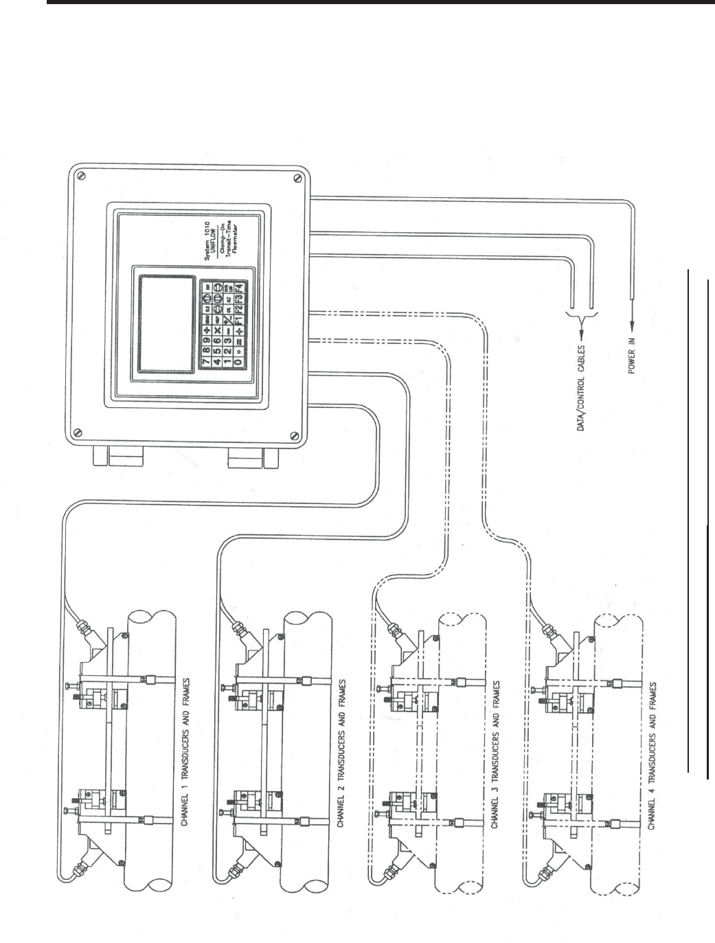
TYPICAL SYSTEM - 1010N PERMANENT CLAMP-ON SYSTEM
Flow Measurement Sub- system ( 4 channel system depicted here)
1.4 THE KEYPAD ENABLE SWITCH
All System 1010N models provide a keypad enable/disable switch to prevent unauthorized access to
the Installation Menu. In addition, a password entry option is available (see Channel Setup). The keypad
enable/disable switch is located inside the lockable enclosure just above the I/O wiring terminal. Please
switch to the enable position before proceeding further. If necessary, see Drawings 1010N-7, 1010DN-
7 or 1010MN-7 for location details.
1-3
1010NFM-3JSection 1
1.5 THE 1010N KEYPAD
The 1010N integral keypad provides 32 numeric and function keys (see table below). Use these keys to
enter, review or edit the site data. Certain keys control the graphics display, Datalogger and Totalizer.
“Blind Models,” having no keypad or display, must be setup by using their serial data port (see Appen-
dix B).
NOTE: The keypad does not have alphabetic keys. Scrolling lists provide alphanumeric char-
acters as needed.
1.6 INTRODUCTION TO THE 1010N MENU SCREENS
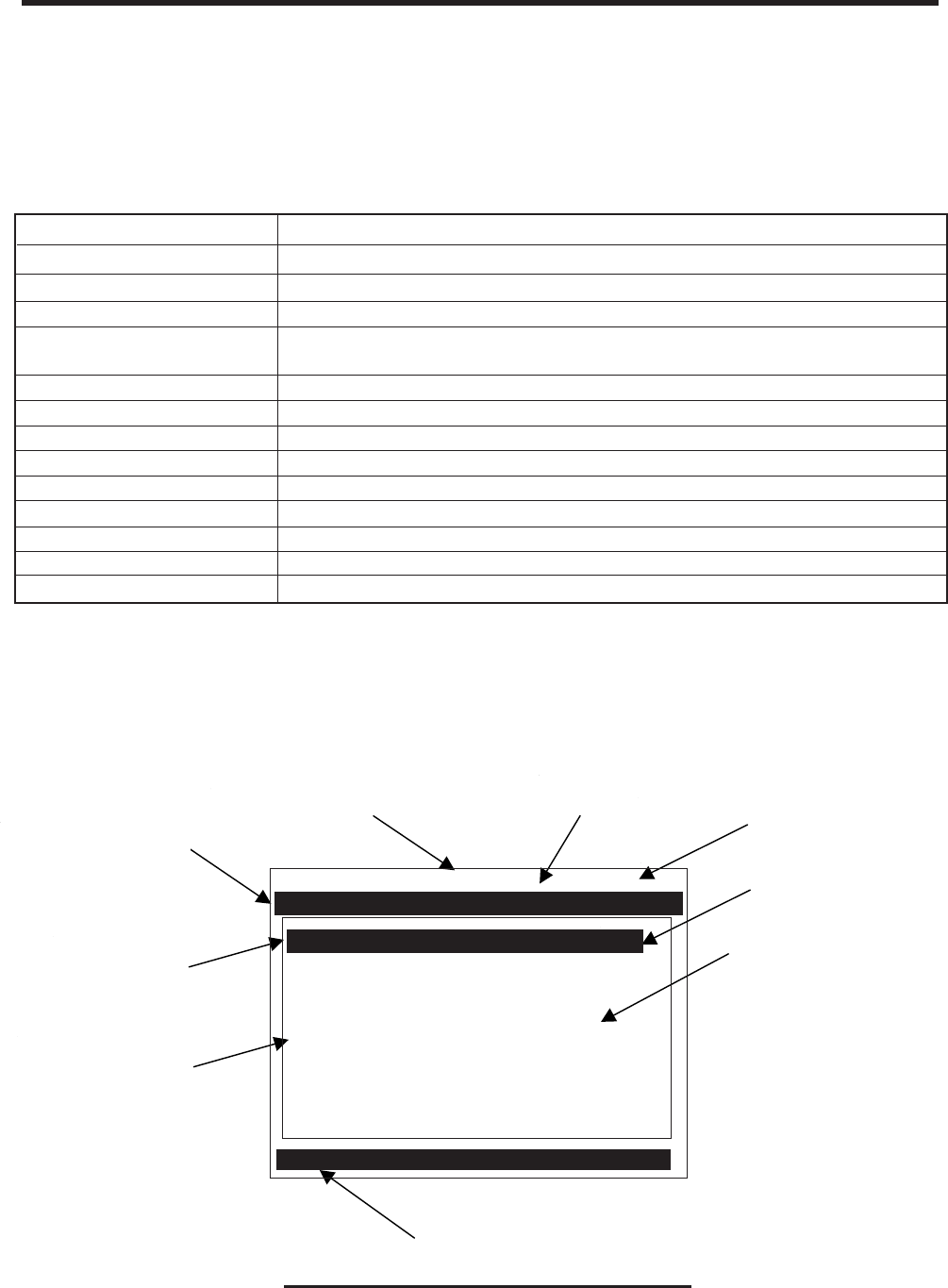
The figure below shows a typical 1010N menu screen (in this case, the Pipe Data Menu).
Highlighted Data
Site Name Identified
TYPICAL INSTALLATION MENU SCREEN
Menu Cell Data
(right-hand column)
Current Selected
Measurement
Channel
Current Selected Menu
Current Selected
Meter Type
Highlighted
Menu Cell
Menu Cell Data
(left-hand column)
Menu Prompt Line
(Reverse Video)
Siemens 2 Channel [1] SITE 1
Select Pipe Class Manual Entry
Select Pipe Size No Pipes
Pipe OD <in> 0.500
Pipe Material Steel
Wall Thickness 0.100
Liner Material None
Liner Thickness 0.000
Pipe Dataiquid Class
Select Pipe Class from Pipe Table
KEYPAD FUNCTION CHART
MENU Press to activate the Installation Menu.
ENT Press <ENT> to store numeric data, select from option lists, etc.
LEFT, RIGHT ARROWS Menu navigation keys move cursor in respective directions.
UP, DOWN ARROWS Same as <Left> and <Right>. Also scrolls option list and graphic
display screen.
CLR Clear Key for erasing data, or selecting list options.
NUMBERS 0-9 Use to type numeric data.
DECIMAL POINT Use for decimal points in numeric data.
MATH OPERATORS Allows 4-function math operations in numeric entry cells.
“F” KEYS 1-3 Totalizer control and special function keys.
“F4” KEY CAUTION: SYSTEM RESET KEY (during power up)
CTL & ALT Used as shift keys for alternate key functions.
DATALOG Triggers immediate Datalogger report.
PLUS/MINUS [+/-] Changes the sign of numeric data.
KEY USAGE

1-4
1010NFM-3JSection 1
1.7 HOW TO USE THE INSTALLATION MENU
This section introduces the System 1010 Installation Menu. It explains how to access and leave the
Installation Menu and how to enter site data. The Installation Menu consists of sub-menus, each pro-
viding individual menu locations (menu cells) that store site data. For convenience, this manual refers
to sub-menus simply as menus (e.g., the Pipe Data Menu). Shown below is the Clamp-on, Full Site
Setup screen for Channel 1 of a dual-channel meter. Single and four channel systems are identical.
Siemens 2 Channel [1]
Create-Name-Recall-Enable & Delete Site
Pipe Data
Application Data
Pick/Install Xdcr
Operation Adjust
Flow/Total Units
Data Span/Set/Cal
Stripchart Setup
Datalogger Setup
I/O Data Control
Diagnostic Data
Channel Setup
Clamp-on
EXPLANATION OF THE CALL-OUTS
Menu Prompt Line When you select a menu cell, a highlighted text prompt appears on the top of
the screen to explain the function of the cell.
Current Selected [2 Channel] indicates Dual Channel meter operating mode selected.
Meter Type
Selected Channel The [1] indicates that measurement Channel 1 is currently selected.
Highlighted Menu The menu cursor (highlight bar) shows where you are currently working by
Cell reversing the display colors for that cell (white type on black).
Highlighted Data The right-hand column shows the current value highlighted. Pressing the
<Right Arrow> provides access to an option list or numeric field where you
can change the current value as required.
Menu Cell A menu cell is an individual location within a menu (in this case Pipe Data)
that stores a parameter (either a numeric entry or an option list selection.
Menu Cell Data The right-hand column shows the current value stored by left-hand column
menu cell. The Pipe Data Menu includes option list items and numeric entries.
Current Selected The highlighted bar at the bottom of the screen shows the name of the menu
Menu that you are accessing (e.g., Pipe Data).
1-5
1010NFM-3JSection 1
1.7.1 ACCESSING AND LEAVING THE MENU
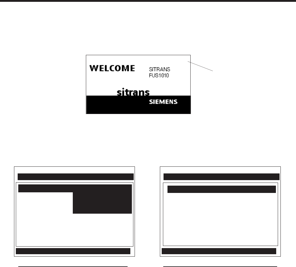
Upon first turning the meter on you see a Siemens graphic. This means that there is no active site
setup currently stored in memory. Note that this screen identifies the software version of the meter on
the upper right-hand corner of the display.
Make sure the keypad enable switch is in the correct position then press the <MENU> key to select the
menu. The first time you access the Installation Menu, you can leave it only by saving a site or by
turning the meter off. After installing and activating a site, use the <MENU> key to toggle between a
graphic display screen and the last accessed menu location.
Top menu screen for dual-channel system Top menu screen for single-channel system
When you press the <MENU> key, the cursor arrives at the first level of the installation menu. Refer to
the sample screens above. The left screen is from a dual-channel model. The right screen is from a
single channel model. Note that two columns, one on the left-hand side and the other on right-hand
side, divide the screen. The first left-hand item, [Meter Type], is highlighted (white type on black). [Meter
Type] allows you to choose a meter configuration from the highlighted right-hand column list. With
single channel models, the only option is [Single Channel]. The next left-hand selection is [Meter Facili-
ties]. Use the [Meter Facilities] menu to set global meter options and controls.
1.7.2 HOW TO ENTER DATA
The left-hand column shows the menu cells (described previously). Another way to think about left-
hand column items is to consider them menu questions. Then you can see that the right-hand column
answers these questions. Right-hand column answers can be:
zAnother series of menu cells (may become left column items when selected).
zAn item from a scrollable option list (e.g., a class of liquids).
zA numeric entry (e.g., a pipe outer diameter).
zAn alphanumeric string (e.g., a site name).
Siemens 2 Channel [1] Channel 1
Select Meter Type
Meter Facilities Dual Beam Flow
Using the Menu Ch 1 + 2 Flow
Ch 1 - 2 Flow
Meter Type >Dual Channel Flow
Liquid Class
Siemens Site [1]
Select Meter Type
Meter Facilities
Meter Type Single Channel
ver. 3.01.00
Software
Version
(x.xx.xx)

1-6
1010NFM-3JSection 1
Selecting Items from an Option List
Examine the screen below. It shows how to use an option list to select a liquid for your application. How
to access this menu will be explained later. Note that the menu name [Application Data] appears
highlighted on lower left of the screen. Note also that the menu cell [Liquid Class] is highlighted - the
right-hand column shows the answer [Water 20C/68F].
Pressing the <Right Arrow> changes the left-hand column to [Select Liquid]. Pressing the <Right Ar-
row> again accesses the option list. This expands the highlighted area to show the list contents. Note
that a cursor (arrow) points to the top item on the list.
The <Up and Down Arrows> scroll the option lists. Every press moves the cursor to the next item in
sequence. Due to the size of display screen, some option lists include more items than the display can
show. For example, on the screen above the last option shown is [Acetic Acid]. However, this option list
has more listings. Continue to press the <Down Arrow> to see more liquid selections. When you arrive
at the last item on a list, the next <Down Arrow> press brings you back to the top of the list; because
the option lists are of the “wrap-around” type.
To select an option list item, move the cursor to the item and then press the <ENT> key.This places
your selection at the top of the list and moves you out of the option list to the next menu cell. Examine
screen on next page. The option list item: [Diesel Fuel] has been selected. Note that this appears on
the right-hand column and that the highlighted area moves to the next menu cell in sequence: [Esti-
mated Vs m/s].
Liquid Class
Access Liquid Option List
Estimated Vs m/s Water 50C/122F
Viscosity cS Water 75C/167F
Density SG ens Water 100C/212F
Water 125C/257F
Water 150C/302F
Water 175C/347F
Water 200C/392F
Water 225C/437F
Water 250C/482F
Acetic Acid
Select Liquid >Water 20C/68F
Siemens 2 Channel [1] Channel 1
Siemens 2 Channel [1] Channel 1
Select Liquid Class from Liquid Table
Temperature Range -40F to 250F
Pipe Configuration Fully Developed
Anomaly Diams 10
Liquid Class Water 20C/68F
Application Data

1-7
1010NFM-3JSection 1
Multiple Select Option Lists
Certain option lists allow you to make more than one selection. For instance, the Datalogger Data
option list allows you to select any or all of the available data items for your reports. You can use the
<Up and Down Arrows> to move the cursor through the list. If you press <ENT> to select an item, a
plus sign (+) appears next to that item. The cursor remains so that you can make other selections. To
deselect a previously selected item, move cursor next to that item and press <CLR>. Use <Left Ar-
row> to leave a multiple select option list.
Entering Numeric Data
When a menu cell requires a numeric answer, press the <Right Arrow> to access a number entry
field; an equal sign (=) appears before current entry. You can now use the number keys and the deci-
mal point key to type a new value. If applicable, you can use <+/-> keys to change the mathematical
sign of the number. Press <ENT> to store the numeric data.
NOTE: All Numeric Data cells provide a four-function calculator via the keypad’s arithmetic
function keys.
Siemens 2 Channel [1] Channel 1
Select Liquid Diesel
Estimated Vs m/s 1600
Viscosity cS 2.00
Density SG 1.030
Access Liquid Option List
Liquid Class
Siemens 2 Channel [1] 1
Datalogger Mode +Site Id
Datalogger Data +Date
Log Time Interval +Time
Datalogger Events Flow
Display Datalogger +Average Flow
Raw Flow
Total
Select Datalogger Data
Liquid Class
Siemens 2 Channel [1] Channel 1
Select Pipe Class Manual Entry
Select Pipe Size N/A
Pipe OD (in) = 0.500
Pipe Material Steel Flow
Wall Thickness 0.100
Liner Material None
Liner Thickness 0.000
Enter pipe Outer Diameter manually
Pipe Data

1-8
1010NFM-3JSection 1
Entering Alphanumeric Strings
An alphanumeric string is a series of numbers and letters; and also the Quotation Mark and the Pound
Sign symbol. You can also use a space. The meter uses these to identify a specific site setup or user-
modified table. The 1010N keypad does not provide letter keys. However, when you access a menu
cell that requires an alphanumeric string answer, the menu cell right-hand column provides an eight-
character entry field. Press the <Right Arrow> to access the field. This selects the first character
position. Note that the prompt changes to a question mark (?). With the cursor at the first character
position, use the <Up> or <Down Arrows> to scroll through a single-character list. For example, as
shown below, an <Up Arrow> at the first character position produces the letter: uppercase [A]. Press-
ing the <Right Arrow> moves the cursor to the second position.
Use the <Right and Left Arrows> to move through the character positions. If you wish touse numbers
in your string, you can type them directly from the keypad. After you finish selecting your string, press
<ENT> to register it.
1.7.3 THE METER TYPE MENU
This is the first list presented upon entering the Installation Menu. Select the type of meter required for
your application. The meter automatically conditions Installation Menu choices to suit the selected
meter type. The following paragraphs introduce the available meter types for dual channel systems.
NOTE: On Single Channel systems, you do not get a choice of meter types, sincethis requires
two independent measurement channels. However, you can operate the single chan-
nel with any optionally supplied measurement technology. Some four channel models
provide four-path and channel summing operation.
Controlotron Dual Path Channel 1
Recall Site Setup
Channel Enable No
Create/Name Site ?A
Site Security Off
Delete Site Setup No Sites
Save/Rename Site
Right Arrow & Enter Creates a new Site
Channel/Path Setup
1-9
1010NFM-3JSection 1
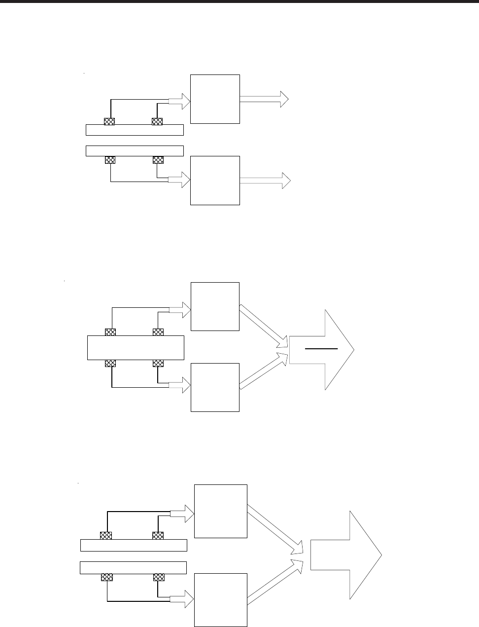
Dual Path
Dual Path uses two measurement channels to achieve a single output via a “virtual” third channel. The
resultant data is the average of the two channels. Only clamp-on or in-line transit-time operation al-
lowed. Benefits include highest available precision and enhanced immunity to distorted flow profile
conditions.
Channel 1+2 and Channel 1-2
Arithmetic operation produces data output via a virtual Channel 3, proportional to sum or difference of
the liquid and energy flow of two independent pipes. This requires setting the two channels to operate
independently. Only clamp-on or in-line transit-time operation is supported.
Channel 1-2 produces a data output via a virtual Channel 3, proportional to the difference of the liquid
and energy flow of two independent pipes. You have to set-up the two channels independently. Only
clamp-on or in-line transit-time operation is supported.
Channel 1
Flow
Channel 2
Flow
PIPE `A'
PIPE `B'
Pipe 'A' Flow Rate
Pipe 'B' Flow Rate
Channel 1
Flow
Channel 2
Flow
Ch1 + Ch2
2
Output
(average of
Ch 1 & Ch 2)
Pipe
Dual Channel
Dual Channel provides two independent measurement channels that operate simultaneously. De-
pending on the specific model, Dual Channel supports: Clamp-on Transit-time, In-line Transit-time,
Reflexor.
Output
sum or difference
of Ch1 & Ch2
Channel 1
Channel 2
PIPE `A'
PIPE `B'
PIPE `A' FLOW RATE
PIPE `B' FLOW RATE
Ch1 [+/-] Ch2

1-10
1010NFM-3JSection 1
1.7.4 ESSENTIAL INFORMATION FOR USERS OF MULTI-CHANNEL 1010’s
Multi-Channel Meter Type
If your 1010 is a multi-channel model, it offers 2 or 4 independent measurement channels. The meter’s
resources are divided among these channels equally. This means that analog Input/Output, relays
and digital command lines will be fewer than for single channel machines. We’ll show you later how to
“get around” this limitation for times when you need all your multi-path meter’s resources for a single
measurement channel.
If one, two or three channels are running when you are trying to setup the last channel, it could take a
very long time for the setup; some 10 to 15 minutes should be expected. A great time saver would be to
turn each channel off after setup (setup one channel at a time) and reactivate all after everything is
setup; then the setup time goes very quickly.
Your datalogger and site storage memory, being bulky resources, are not divided up at all, and
remain available for each channel’s use. You will be able to save and recall sites to and from the
various channels as long as they share an identical measurement technology (Reflexor, clamp-on,
flowtube, etc.). Be aware, however, that moving a site from one channel to another like this, will likely
require a new initial installation to achieve its best potential. This is especially true if the new target
installation is not on the same pipe or uses another pair of transducers whose nominal characteristics
are identical. Note that datalogger reports will be interleaved in memory and their frequency is con-
trolled by the interval that was selected for each channel. Providing each site with a unique name will
enable you to sort these out when analyzing the data later.
Arithmetic Operation
The dual channel instruments provide a modality of operation which permits the user to arithmetically
combine (through addition or subtraction) the results of the two independent measurement channels.
Installation of each channel is done via the dual channel menu. Site Saving and Recalling automati-
cally recall the contributing sites. While the displays for each physical channel provide you all the data
(flow rate, totals, etc.) that are provided via independent channel operation, user Input/Output is largely
oriented toward the virtual channel - Channel 3.
Multi-Path Operation
In many cases, the performance of an ultrasonic transit time meter can be improved by allowing it to
interrogate the flow field with more than one beam. Imperfect flow profile conditions such as non-axial,
cross-flow or an off-center higher-rate flow core, which can cause a single path machine to mis-report
the flow rate, are often remedied in this way. The multi-path installation is similar to arithmetic opera-
tion; except for the fact that the virtual, or output channel has pipe dimension attributes (which in the
arithmetic meter channel it does not). This means that when you install a multi-path meter, pipe data
must be installed in Path 1 and Path 2. Your 1010 meter facilitates this by copying pipe data that you
installed as Path 1 and Path 2 data to the other paths. It is seldom, if ever, necessary to “trim” the pipe
data for the individual path channels - although you may install different size or type transducers for
each path. Once you define the pipe, move the menu to the individual paths using Select Path for the
physical installation of each channel. This is accomplished in the same way that individual channels
are installed.
Save and Restore Operations for multi-path sites execute on all the component chan-
nels simultaneously; the individual paths of multi-path sites do not have any existence or autonomy as
single channel sites. You will also find that individual path channels possess a reduced set of user-
accessible menu functions. For example, although you may zero each individual path, the meter
provides Kc control (slope correction) for the virtual channel (system channel) only. You will find that
the features and functions provide for each physical channel to focus mainly on the physical measure-

1-11
1010NFM-3JSection 1
Selecting A Meter Type
The following example explains how to select a dual-channel clamp-on meter and initiate site program-
ming for the measurement channel. Your [Meter Type] selection, as well as other menu selections, are
“remembered” through power cycles.
NOTE: If you have a single-channel system, all you have to do is select a measurement tech-
nology and then go directly to Channel Setup. The site setup procedure for a single-
channel system is identical to setting up a measurement channel on a dual-channel
system.
As shown in the steps below, selecting this mode only requires key presses. This
is because dual-channel clamp-on is the default configuration for this instrument. To
select a different configuration, move the cursor to the desired Meter Type and then
press to select it.
Make sure that the keypad enable switch is in the [Enable-Up] position. Turn on power
and press to access the [Meter Type] screen. Refer to the figure below.
Note that on the left-hand column, [Meter Type] is highlighted as are all the available
meter types on the right-hand column. Press . This places a cursor next to [Dual-
Channel Flow].
ENT
Siemens 2 Channel [1] Channel 1
Select Meter Type
Pipe Data
Meter Type >Dual Channel Flow
Meter Facilities Dual Path Flow
Ch 1 + 2 Flow
Ch 1 - 2 Flow
MENU
ment task. User output data, however, is mostly reserved for the virtual or system channel. This in-
cludes the totalizer functions. Analog data is largely reserved for the virtual or system channel as well
as the totalizer functions, analog outputs and datalogger. In some instances, access is also provided
to the path channel’s data in order to facilitate the gathering of diagnostic information; thus minimizing
menu clutter, but preserving as much functionality as practicable. Totalizer control via lead-in function
key is provided by F3 (dual-path meter) and, since there is no F5, F1 (four-path version). The Diagnos-
tic Menu area has been similarly setup to provide data (Path 1, Path 2 and Path 1 and 2) generated by
the physical measurement channels when selected, but, to suppress elements only provided by the
virtual channel. As mentioned above, use a partially installed multipath site in order to direct all meter
input/output to a single measurement path. Simply install the single available physical path and you’ll
produce data based on only this physical input and obtain the same functionality as provided to the
single channel user.

1-12
1010NFM-3JSection 1
To select [Clamp-On] press . This selects the Clamp-On Installation Menu for Measure-
ment Channel 1. Note that the first menu, [Channel Setup], is highlighted.
Creating a New Site Setup (See paragraph 2.1.1)
The Channel Setup section of this manual provides detailed instructions on how to use all the Channel
Setup menu commands. This section provides an example of how to use the [Create/Rename Site]
command to create a new site setup. Always begin a new installation by issuing the [Create/Name
Site] command. Although you do not need to enter a site name to create a new site setup, you have to
provide one to save the site setup or to identify the source of logged data. In this example, we will use
[SITE1] for the site name.
To access the [Channel Setup] menu press then move the highlight down to [Create/
Name Site].
Press . Note that the cursor changes to a block, which appears after a question mark (?).
This indicates that you have accessed the first character position of an eight-character (max.)
alphanumeric entry field.
Press the twice. This selects [Dual-Channel Flow] and then places the cursor next to
[Clamp-on] for Channel 1. Note that some models do not support all flow sensor types.
Channel 1 >Clamp-on
Channel 2 FlowTube
Reflexor
Siemens 2 Channel [1] Channel 1
Choose Channel 1 Flowmeter Type
Dual Channel Flow
Siemens 2 Channel [1] Channel 1
Recall Site Setup No Sites
Channel Enable No
Create/Name Site
Site Security Off
Delete Site Setup No Sites
Save/Rename Site
Right Arrow & Enter Creates a new Site
Channel Setup
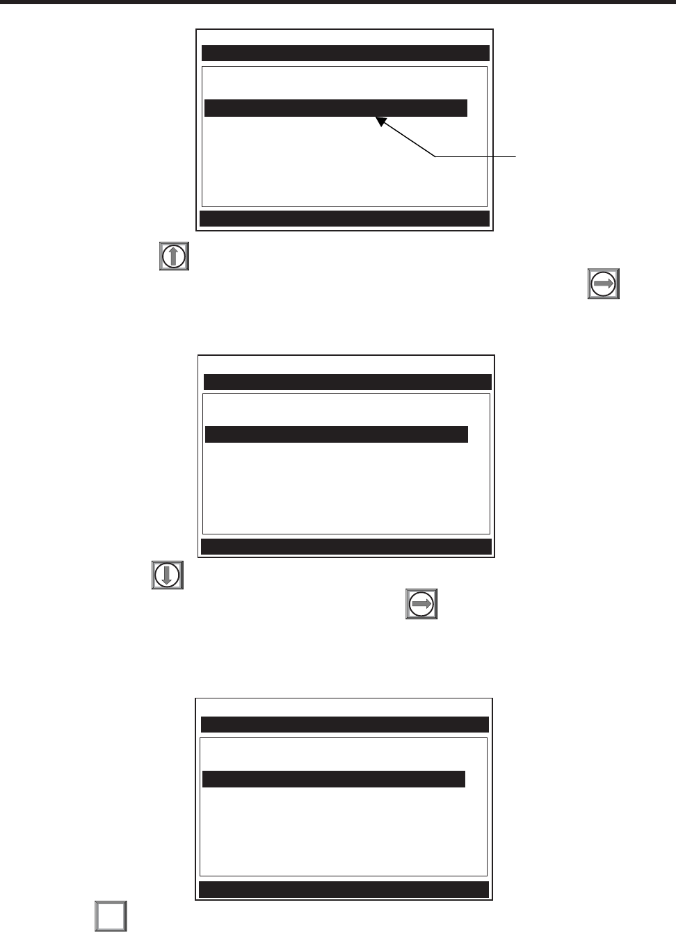
1-13
1010NFM-3JSection 1
Press and hold . Note that the character position begins to scroll upward through the
alphabet of capital letters. Continue to scroll until block cursor shows [S]. Press .
Press and hold . Notice that the capitalized alphabet list begins to scroll downward through
the alphabet from [S]. Stop scrolling at letter [I]. Press to move the block cursor to the third
character position.
Scroll back up to letter [T]. Move the cursor to the fourth character position. Scroll down to letter
[E]. Move the cursor to the fifth character position. Type [1] on the numeric keypad to complete
the site name.
Press to create the site setup named [SITE1]. Note that the name now appears in the
[Save/Rename Site] menu cell and on the upper right corner of the graphic screen.
ENT
Siemens 2 Channel [1] Channel 1
Recall Site Setup No Sites
Channel Enable No
Create/Name Site ?S
Site Security Off
Delete Site Setup No Sites
Save/Rename Site
Right Arrow & Enter Creates a new Site
Channel Setup
Siemens 2 Channel [1] Channel 1
Recall Site Setup No Sites
Channel Enable No
Create/Name Site ?SITE1
Site Security Off
Delete Site Setup No Sites
Save/Rename Site
Right Arrow & Enter Creates a new Site
Channel Setup
NOTE: The character [S] remains at the first character position and the block cursor moves to
the second character position.
Siemens 2 Channel [1] Channel 1
Recall Site Setup No Sites
Channel Enable No
Create/Name Site ?
Site Security Off
Delete Site Setup No Sites
Save/Rename Site
Right Arrow & Enter Creates a new Site
Channel Setup
This block cursor is
currently placed at
the first character
position.
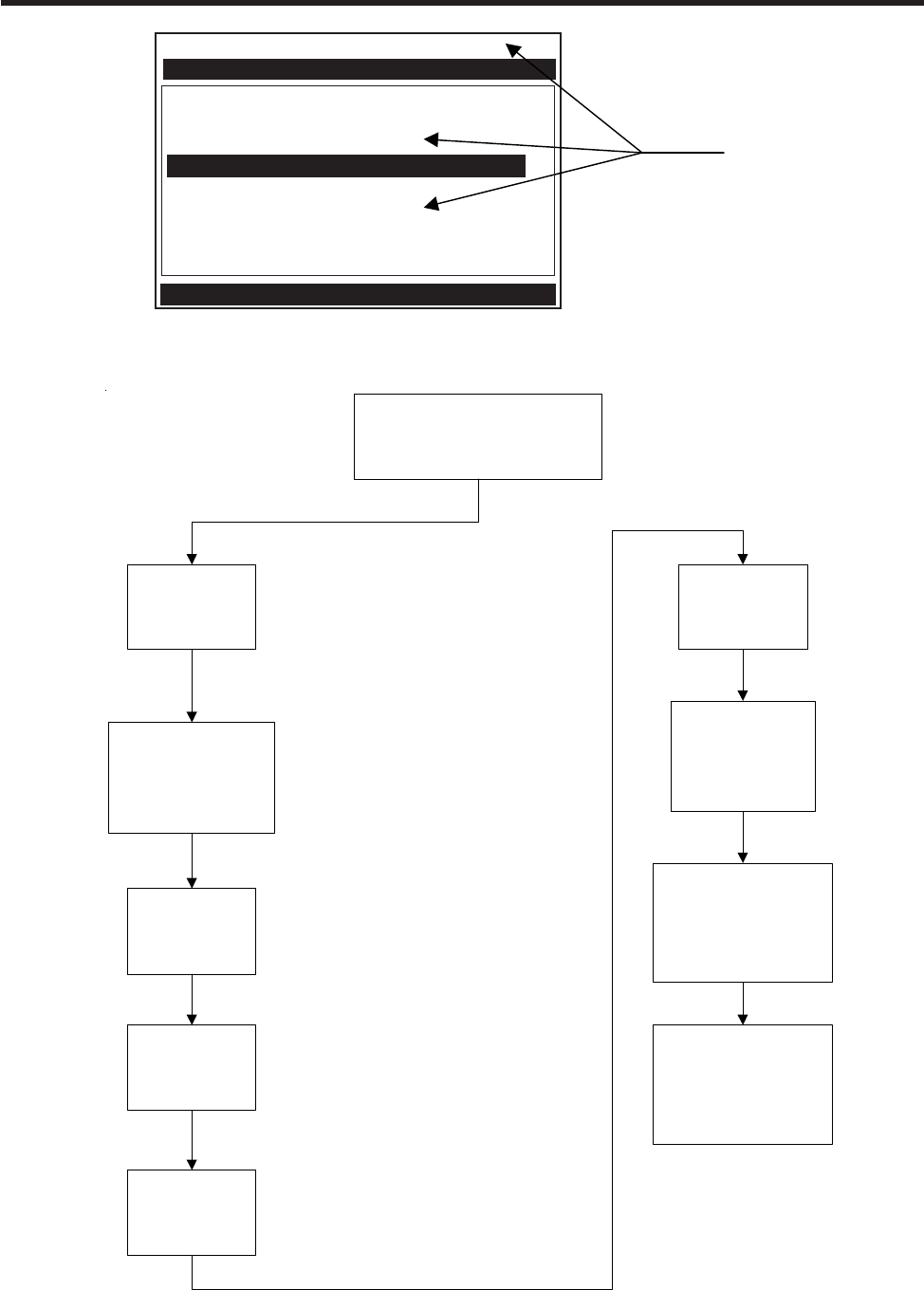
1-14
1010NFM-3JSection 1
Flowmeter Installation Flowchart
Flowmeter Installation
Collect Site
Data
Choose Mounting
Location For
Flowmeter and
Transducers
Prepare Pipe
Surface
Access
Installation
Menu
Create a Site
Enter Pipe
Parameters
Invoke
Transducer
Install
Procedure
Mount Transducers
on Pipe and
connect Flowmeter
Complete
Transducer
Installation Menu
Operations
Siemens 2 Channel [1] SITE1
Recall Site Setup No Sites
Channel Enable No
Create/Name Site SITE1
Site Security Off
Delete Site Setup No Sites
Save/Rename Site SITE1
Use with Care -- Turn Security On or Off
Channel Setup
After creating a Site
Setup, the assigned
name appears in
these places.
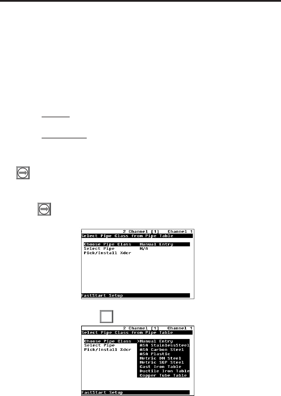
1-15
1010NFM-3JSection 1
1.8 USING FASTSTART SETUP
The dual-channel clamp-on mode offers a choice of using FastStart Setup or Full Site Setup to create
your site setup. As its name implies, FastStart Setup is a quick way to start up the meter. FastStart
inserts default settings into all applicable menu cells. However, these can be edited later via the Full
Site Setup menu. In order to use FastStart Setup:
zYour pipe must be included on the meter’s pre-set pipe table.
zYour liquid is water, or has similar sonic characteristics.
FastStart setup is actually a shortcut to these two menu locations (where data entry is mandatory for a
successful start-up):
zPipe Data: The Pipe Data Menu is limited to the selection of pipe pre-sets only. There
are no provisions for manual pipe editing.
zPick Install Xdcr: This is the same menu as Full Menu Setup (see paragraph 1.7).
Press to access the Pipe Class option list. Note that although [Manual Entry] exists on this
list, it is inactive for FastStart Setup (see paragraph 2.2.1).
1.8.1 CHOOSING THE PIPE CLASS/SIZE
Press to access [FastStart Setup]. This selects [Choose Pipe Class]. There are over sixty English
and metric pipe sizes for eight different classes of pipes. Picking a pipe class and size automatically
sets all the required pipe parameters using industry standard dimensional data.
In this example, we will pick the pipe class: [ASA Carbon Steel] by moving the cursor to the
selection and then pressing .
ENT
Siemens
Siemens
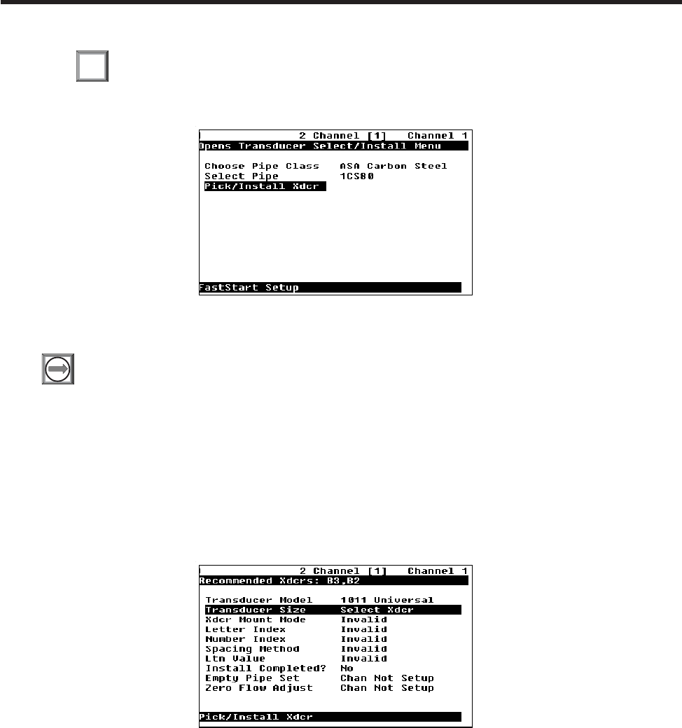
1-16
1010NFM-3JSection 1
Next, we will pick the pipe size: [1CS80] by moving the cursor to the selection and then press-
ing . This is all there is to setting up the pipe parameters.
Now, we will select and install the transducers.
ENT
1.8.2 PICKING AND INSTALLING THE TRANSDUCERS
Press to access the Pick/Install Xdcr menu, then select the appropriate Transducer Model. The
meter then analyzes your pipe data and registered transducer list before calculating the recommended
transducer size(s). The top-line prompt shows a series of transducer recommendations, that are
listed in order of priority from left to right. Select the appropriate transducer size with consideration
given to the computed transducer recommendations. In the example below we will install the “B3”
transducer size.
After you make your transducer selection, the meter automatically computes the preferred mounting
mode and transducer spacing index.
Note the Number Index value.
This value corresponds to the index marked on the spacer bar or mounting track. The value of Ltn
represents the actual distance in inches or mm, between the front surfaces of the upstream and
downstream transducers.
NOTE: The meter only indicates the part number of the 1011 Universal Transducer mounting
track or spacer bar. It does not indicate this information for other transducer types.
Siemens
Siemens
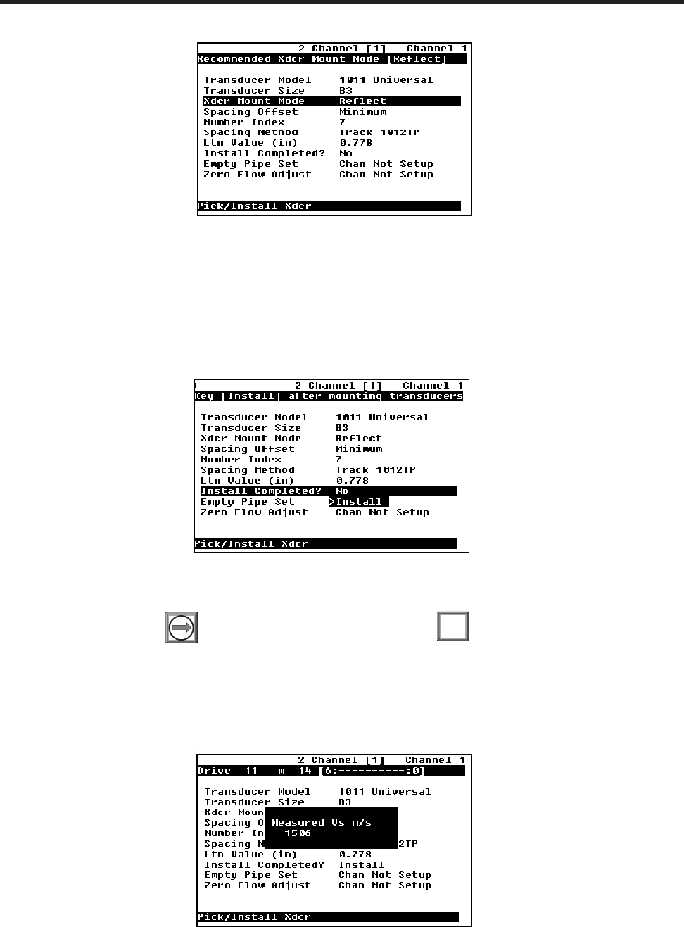
1-17
1010NFM-3JSection 1
NOTE: You are allowed to override the transducer type and size mounting mode and spacing
offset. See paragraph 1.7.
Now you have to mount the transducers in accordance with the data recommended on the screen.
Refer to the Section 3 for detailed instructions. The pipe must be completely filled with a liquid for the
initial installation of the meter. Make sure that you do not install your transducers backwards or reverse
the Upstream and Downstream cables.
Use the [Install Completed?] menu cell to inform the meter that you have finished mounting the
hardware. Press . Move the cursor to [Install]. Press .
The meter performs an Initial Makeup which conditions its operation to the selected transducer, pipe
and liquid and then sets the empty pipe and the zero flow levels automatically. Be patient! The Initial
Makeup performs a number of operations including a frequency sweep of the pipe wall resonance,
which could take several minutes.
ENT
Siemens
Siemens
Siemens

1-18
1010NFM-3JSection 1
The meter is now ready to report flow. Press . The meter will then ask you to save the Site.
Saving the Site is optional and will therefore be covered in paragraph 1.7. To abort this item,
press . This brings up a Flow Display Screen.
Once your site has successfully installed, you can press to scroll between the avail-
able display screens.
The meter is now operational and the display will show flow by pressing the <MENU> key.
Now that you are familiar with the 1010N setup, take the time to read the information about the Installa-
tion Menu in Section 2. Becoming acquainted with the various flowmeter setups in the Main Menu will
help further your understanding of the 1010N.
Upon completion, the meter reports the measured liquid sonic velocity. Press . The flowmeter will
then automatically perform an AutoZero operation, where the meter measures any zero flow offset,
which is used to correct the flow reading. This operation occurs only when the transducers are mounted
in the reflect configuration and is independent of whether or not the liquid is flowing.
After the AutoZero operation is complete, the meter may ask you to register the transducer used in this
installation. It is advisable that you register your transducers, since the registration list is used to
condition the transducer recommendation.
Press and select [YES], or [NO] if you do not want to register this transducer and then,
press .
ENT
MENU
Siemens
0.20
Siemens 2 Channel [1] Channel 1
FLOW GAL/MIN
TOTAL KGAL Vs
89.68
G/M
0.00
0.12 Vfo
1474
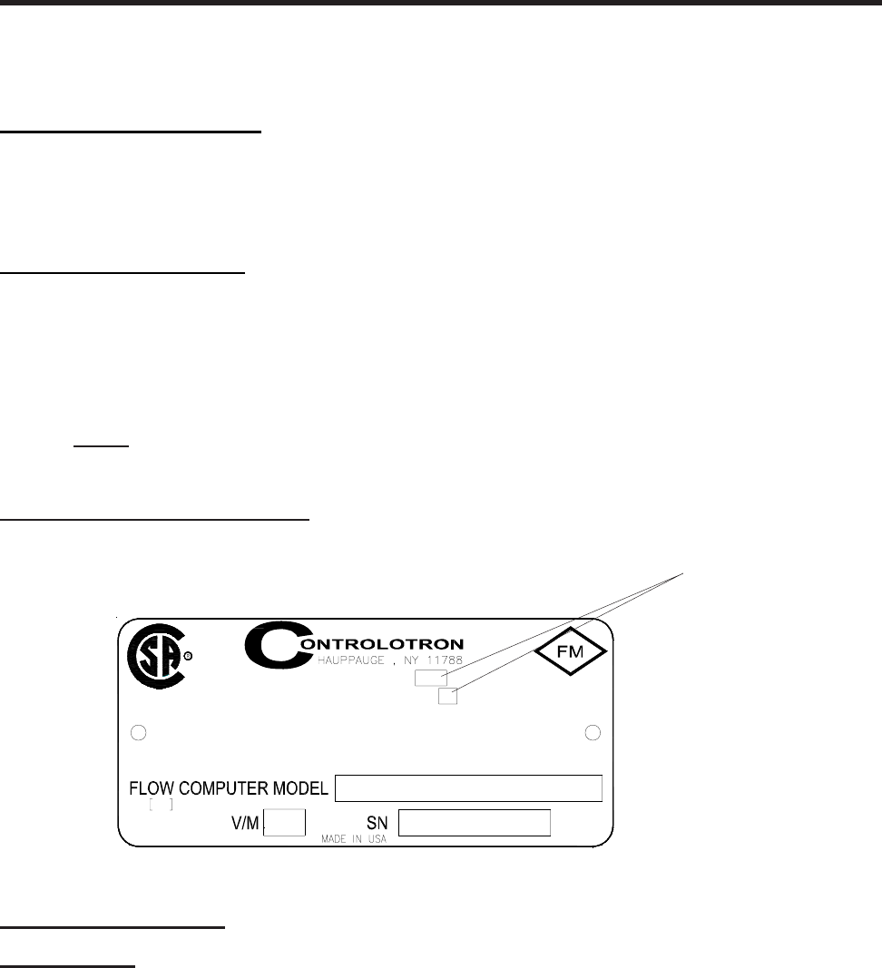
1-19
1010NFM-3JSection 1
1.9 1010WX CLAMP-ON LIQUID FLOWMETERS
The 1010WX flowmeter model numbers are listed below.
1010WX Series Flowmeters
1010WX
1010DWX
1010MWX
1010WX METER TYPES
The 1010WX series flowmeters are available in Single, Dual Path and Multi-Path versions. The
flowmeters may include a display providing flow rate, diagnostics data and keypad interface to access
on-screen software setup menus. Safety agency approved 1010WX series flowmeters have hazardous
area certification as indicated in the label example below.
NOTE: Graphic displays and local keypads are only available as options. The standard 1010WX
is not equipped with a graphic display or local keypad. Refer to Appendix B in this
field manual for hardware and software requirements for programming these models.
1010WX FLOWMETER LABEL
SYSTEM HARDWARE
ENCLOSURE:
The System 1010WX Series flowmeters have two available case configurations:
Standard 1010WX Case
The System 1010NWX Series flowmeter housed in a cast aluminum enclosure suitable for gas
groups up to and including hydrogen (Class 1, Zone 1, AEx d [ia] IIB +H2 T5).
Alternate Light Weight 1010WX Case
The System 1010WX Series flowmeter housed in a lightweight cast aluminum case suitable for gas
groups up to and including propane (Class 1, Zone 1, AEx d [ia] IIB T5).
INSTALL PER CONTROLOTRON DRAWING 1010-443
RATING: 250 VAC OR 36 VDC MAX. 25 W
CIRCUITS ARE ALIVE. CONDUIT SEALS MUST BE INSTALLED WITHIN 18" OF THE ENCLOSURE
CAUTION-DISCONNECT FROM SUPPLY BEFORE OPENING. KEEP COVER TIGHT WHILE
CL I, DIV 2, GROUPS A, B, C, D SUITABLE FOR CL II, DIV 2, GROUPS E, F, G
EXPLOSION PROOF WITH I. S. OUTPUTS FOR CL I, GROUPS C, D, CL II, GROUPS E, F, G
ENCL. TYPE 4X IP66
Exia
Associated
Apparatus
CLASS 1, ZONE 1, AEx d [ia] IIB T5
A
PPROVED
+H2
B
Blank unless flowmeter is rated suit-
able for hydrogen atmosphere. See
“System Hardware” description be-
low.

1-20
1010NFM-3JSection 1
Standard Case Enclosure with Window includ-
ing the 1010WX equipped with optional graphic
display and local keypad.
Standard Case Enclosure without Window includ-
ing the 1010WX equipped with optional graphic
display and local keypad. (Shown with cover
opened.)
ELECTRONIC MODULES:
All standard 1010DN and 1010MN flowmeter modules are available in the 1010WX series. See the
appropriate manual section for functionality of these modules.
DISPLAY AND KEYPAD OPTIONS
The standard 1010WX flowmeters are not equipped with a graphic display or local keypad. The local
display and keypad are options that can be combined with different case enclosure configurations,
which include the standard case with a window, the standard case without a window, the lightweight
case with a window and the lightweight case without a window.
CAUTION: Consult local codes for permit needed to setup units using the graphic display and
local keypad. Setup must be done with cover opened.
03
6
1
45
2
978
3
6
1
45
2
978
0

2-1
1010NFM-3J
Section 2
2. THE 1010N INSTALLATION MENU
Programming System 1010N requires no special experience or training. This field manual contains all
the necessary information. If you intend to connect this instrument to an external device, then please
have the instruction manual for the device available for reference. The following paragraphs present a
generic menu reference that applies to all configurations of 1010 NEMA meters. Please refer to the
Reflexor and Flow Tube sections for instructions specific to those operating modes.
This section contains a general description of how to enter site setup data via the 1010N Installation
Menu. It assumes that you have already selected a meter type as described in the Getting Started
section. For convenience, it presents the Installation Menu in the same sequence as it appears on the
menu screen. Please note, however, that it is not necessary to program the meter sequentially.
The conventions used with these instructions are:
zWhen the text refers to a keypad key, it will be enclosed in “less than” (<) and “greater than” (>)
symbols: e.g., <MENU>, <ENT>, <Up Arrow>, etc. Where a visual of the key is shown; this means
press this key.
zWhen the text refers to a menu or menu cell name, it will be enclosed with square brackets: e.g.,
[Pipe Data], [Channel Enable], etc.
zEach menu includes an image of its main screen and a diagram of its structure. The rightmost
column of the structure diagram lists the option list choices of the menu cell, if applicable.
General Installation Menu Notes:
zIf a power failure occurs while you are entering or editing data, the entered data may not be retained
in Active Memory.
zAlthough you can operate the meter immediately after completion of the site setup, we recommend
that you preserve your settings by saving them under a site name. Site data can be saved at any
time before invoking either the [Recall Site Setup] or the [Create/Rename Site] commands. When
issued, these commands overwrite all data present in Active Memory.
zWe do not recommend that you attempt to operate the flowmeter at a new site by recalling and then
editing an existing site setup. Each site must have its own set of transducer install parameters,
even if the data from the recalled site setup is identical. Always issue the [Create/Rename Site] to
begin a new site setup. This will fill all the menu cells with defaults to eliminate the possibility of
retaining unwanted parameters.
zThe meter allows you to create your own personal site setup defaults. After creating asite setup
and editing default parameters as desired, save the site using the name [FASTSTRT]. The next
time you issue the Create/Name Site command, your custom parameters will become the system’s
defaults.
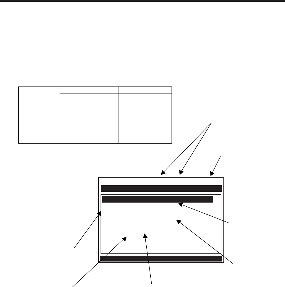
2-2
1010NFM-3JSection 2
2.1 THE CHANNEL SETUP MENU
Available after picking a meter type and a measurement technology. Use this menu to manage site
setups. You can create, recall, delete and save entire site setups. You can apply Site Security, which
permits read-only access to the Installation Menu unless you enter a password. The Channel Enable
switch allows you to disable and enable a measurement channel. *Be aware that Site Name option
lists only show sites that are consistent with the currently selected meter type.
2.1.1 HOW TO RECALL A SITE SETUP
The Recall Site command allows you to reinstall the system at a former site. For an original installa-
tion, see Create/Name Site for instructions on how to create a new Site Setup. This menu cell provides
a list of saved site names. Scrolling to a site name and pressing <ENT> moves all the parameters
associated with that name into Active Memory.
If there are no site setups present in site storage memory, the menu cell reports [No Sites] in the right-
hand column. Saving a site setup with a site name adds the name to this option list. The first selection
Siemens 2 Channel [1] XYZ
Recall Site Setup XYZ
Channel Enable Yes
Create/Name Site 1
Site Security Off Flow
Delete Site Setup 1
Save/Rename Site 1
Scroll saved Site Setup list and Enter
Channel Setup
Use this menu cell to free up site storage
memory by deleting obsolete site setups.
Note that the cell retains the name of the
most recently created site setup [XYZ].
This option list expands as you save more
sites.
Use this menu cell at any time
to manually save the site data.
Note that attempting to leave
the menu after entering/editing
any site data triggers a Save
Site pop-up window
automatically.
This cell shows that
site setup [XYZ] is
stored in memory,
and can be recalled.
This option list
expands as you save
more sites.
Use this menu cell to
enable or disable Site
Security. Provide a
password to enable.
Re-enter the
password to disable.
This shows that
the site setup
[XYZ] is the active
site.
Use this menu cell to create and
name a site setup. Note that the
cell retains the name of the
most recently created site setup
[XYZ].
This shows that
the Meter Type is
Dual Channel,
operating with
Channel 1 active.
Channel Setup Recall Site Setup *Site Name List
Channel Enable Yes
No
Create/Name Site *Site Name Entry/Edit
Site Security Off
On
Delete Site Setup Site Name List
Save/Rename Site *Site Name Entry/Edit
CHANNEL SETUP MENU STRUCTURE

2-3
1010NFM-3J
Section 2
on the list is the currently active Site Setup. The system will be ready for operation after you install the
transducers and make the required hardware connections. Note that the installed transducers must
comply with the recalled site parameters.
To recall a Saved Site Setup: (Where a visual of the keys is shown; this means press this key)
To access the list of saved site names press
To move the cursor to the Site Name press
Press .This triggers a pop-up window that asks if you intend to use the original transducer
position (recommended). This means that you have to remount the transducers exactly as they
were in the previous install.
If you cannot recreate the original transducer installation, then press to change the pop-up list
from [Original] to [New].
Press . This disables the measurement channel until you repeat the Pick/Install Transducer rou-
tine.
2.1.2 HOW TO ENABLE AND DISABLE A MEASUREMENT CHANNEL
The flow computer disables a measurement channel until the completion of the required Site Setup
entries and the transducer installation procedure. The meter enables the measurement channel auto-
matically after it receives all required site data and completes the transducer install routine. (The Site
Enable menu cell allows you to disable or enable a measurement channel after there has been a
successful transducer install).
The system does not require your presence for routine operation. If a fault condition (e.g., an empty
pipe) disrupts operation, the system will recover automatically after the fault clears. Use Channel En-
able [No] to turn off a channel that is currently unused but active; for example, if the transducers have
been removed for servicing.
To disable a channel that is operating:
To access the [Channel Enable] option list press
Move the cursor to [No] by pressing
To disable the measurement channel press
To enable a channel:
To access the [Channel Enable] option list press
Move the cursor to [Yes] by pressing
To enable the measurement channel press
ENT
ENT
ENT
ENT
2-4
1010NFM-3JSection 2
2.1.3 HOW TO CREATE/NAME A SITE SETUP
Use this command to create a new Site Setup. This is the first action required for an original installa-
tion. Create/Name Site inserts system defaults in all the appropriate menu cells. You can edit these
defaults as necessary to suit your needs.
You do not have to provide a site name in order to create a new Site Setup. You can create a site simply
by pressing the <Right Arrow> to access the menu cell entry field and then pressing <ENT>. This
creates a “nameless” Site Setup. However, if you intend to use the meter’s multi-site storage facility,
you must enter a unique site name for each site setup you want to retain in site storage memory.
To Create and Name a new Site Setup:
To access the first character position press
To select a character press then to highlight to next character position.
To select the second character press
Repeat this process to select all the characters (8 max.) you want to use to identify the new Site
Setup.
To create the new Site Setup press
NOTE: If you decide to use numbers in the site name, you can type these characters directly
from the keypad.
2.1.4 HOW TO ENABLE/DISABLE SITE SECURITY
With Site Security enabled, the meter will require a password before it allows any activity that could
interrupt or affect system operation. You can still access the Installation Menu. However, Site Security
limits access to the viewing of parameters only. In other words, you will still be able to review site data,
but you will not be able to make any changes.
Activate Site Security with care. Once activated, the only way to deactivate it is via the Site Security
[Off] command. However, the cursor will not move to the Site Security option list until you enter the
correct password. Therefore, it is essential that you never forget or misplace the password. The only
way to deactivate Site Security without knowing the password is to return the unit to Siemens. How-
ever, the process the factory uses to remove Site Security will eliminate any existing Site Data as well.
The flowmeter will allow a <F4> Reset Sequence when Security is active, however, it also contains a
Menu Enable switch that allows you to inhibit this function (see drawing 1010N-7).
To activate Site Security:
To access [Site Security] option list press
To scroll the option list to [On] press then . [Enter Code?] appears at
the top of the display screen.
ENT
ENT
CAUTION: MAKE CERTAIN THAT YOU RETAIN A COPY OF THE PASSWORD IN A SE-
CURE LOCATION.

2-5
1010NFM-3J
Section 2
To select the first character, use the numeric keys or press . To move the cursor
to the first character position press .
To move the cursor to the second character position press .
Repeat the selection process for the second character. Continue this process until all the
required characters (8 max.) appear in the field.
To store code press . [Confirm Code ?] appears at top of the display screen. Retype
code exactly as described above.
Press . This moves the cursor to the [Site Security] option list.
To scroll the option list to [Site Security: On] press . Once you turn on Site Secu-
rity, you must enter the correct code to turn it off.
To activate Site Security press .
2.1.5 HOW TO DELETE A SITE SETUP
If you attempt to save a Site Setup when memory is full, the screen will show [Memory Full]. If you get
this message after issuing a Save/Rename Site command, you’ll have to delete an unneeded Site
Setup to clear memory space. The Datalogger and Site Storage share a common memory pool, so a
large amount of logged data could also trigger the [Memory Full] message. For how to clear Datalogger
memory, see [Meter Facilities/Datalogger Control]. The Defragment Command may also secure more
memory (see Meter Facilities/Memory Control Menu).
To delete a stored Site Setup:
To highlight [Delete Site] press .
To access the [Delete Site] option list press .
Move the cursor to the site name of the site setup you want to delete.
To delete the obsolete site setup press .
2.1.6 HOW TO SAVE/RENAME A SITE SETUP
The Save/Rename Site command copies data from Active Memory to the Site Storage Memory. Saved
Site Setups can be recalled for future use. This menu cell allows you to save a Site Setup at any time
during the programming process. However, you must recall and complete the Site Setup in order to
achieve operation.
When you access the Save/Rename Site menu cell, the name of the most recently created Site Setup
(see Create/Name Site) appears automatically. If this name is acceptable, you can press <ENT> to
save the Site Setup. You can change the listed site name by following the procedure below. You may
select up to eight characters. If you decide to use numbers or a decimal point in the site name, you can
type these characters directly from the keypad.
ENT
ENT
ENT
ENT
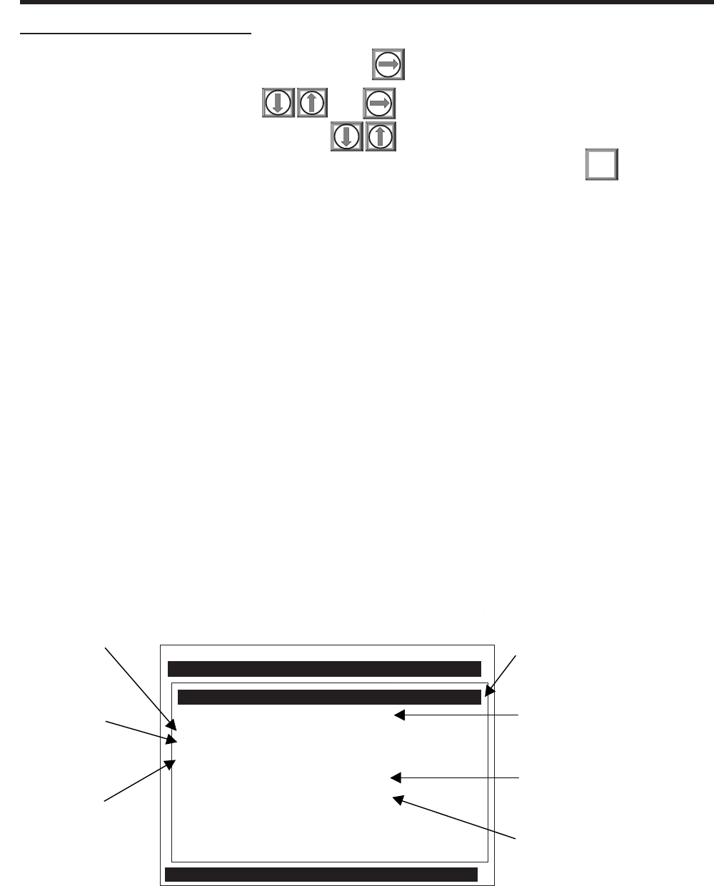
2-6
1010NFM-3JSection 2
To Save or Rename a Site Setup:
To access the first character position press
To select a character press then to highlight to next character position.
To select the second character press . Repeat this process to select all the
characters (8 max.). To save the site data present in Active Memory press .
2.2 THE PIPE DATA MENU
This menu becomes available after picking a Meter Type, Measurement Channel and Measurement
Technology. We recommend that you edit the Pipe Data immediately after creating a new Site Setup.
The Pipe Data menu allows you to define the application’s pipe parameters. Select a pipe from one of
the meter’s stored pipe tables (see menu structure below); or input the pipe size and description
manually. Manual entries include Pipe Material, Outer Diameter (OD) and pipe Wall Thickness. Liner
Material and Liner Thickness entries are included to support pipes with liners. The meter requires the
pipe outer diameter (OD) and wall thickness to operate. You must define these parameters to com-
plete the installation.
The pipe table includes descriptions for over sixty standard pipes plus any user-entered pipes (see
Meter Facilities). To use these presets, first pick a Pipe Class (e.g., ASA Stainless Steel), then pick a
pipe size within that class (e.g., 4SS10). When you select a particular pipe class/size, the relevant pipe
parameters appear in the Pipe Data menu cells. If a given pipe class/size does not match your applica-
tion exactly you can still edit each individual parameter to fine-tune your selection. In addition, the Meter
Facilities section of the Installation Menu provides a pipe table editor that allows you to customize any
or all of the stored pipe tables.
NOTE: If you edit the pipe parameters after the system is operating, you will have to repeat
the transducer install procedure.
ENT
Siemens 2 Channel [1] ABC
Select Pipe Class from Pipe Table
Select Pipe Size No Pipes
Pipe OD <in> 0.500
Pipe Material Steel
Wall Thickness 0.100
Liner Material None
Liner Thickness 0.000
Select Pipe Class Manual Entry
Pipe Data
Use this menu
cell to edit the
wall thickness.
Use this menu
cell to edit the
pipe material.
Use this menu
cell to edit the
pipe outer
diameter.
Use this menu cell to edit
the pipe liner thickness.
Use this menu cell to
select a pipe liner
material.
After picking a pipe class,
use this menu cell to
select a pipe from within
that class.
Use this menu cell to select a Pipe
Class from one of the meter's presets.
The [Manual Entry] selection (default)
means that you enter pipe data
manually.

2-7
1010NFM-3J
Section 2
Pipe Data Select Pipe Class Manual Entry
ASA Stainless Steel*
ASA Carbon Steel
ASA Plastic
Metric DN Steel
Metric SGP Steel
Cast Iron Table
Ductile Iron Table
Copper Tube Table
Select Pipe Size Manual Entry Set pipe parameters manually
ASA Stainless Steel* ASA Carbon Steel ASA Plastic
1SS10 1CS40 1P40
2SS10 1CS80 1P80
3SS10 2CS40 2P40
4SS10 2CS80 2P80
6SS10 3CS40 3P40
8SS10 3CS80 3P80
Metric DN Steel 4CS40 Steel 4CS40
50 DN 4CS80 4P80
100 DN 6CS40 6P40
200 DN 6CS80 6P80
400 DN 8CS40 8P40
800 DN 8CS80 8P80
Metric SGP Steel 10CS XSteel 10P XS
20A-SGP 10CS40 10P40
25A-SGP 12CS STD 12P STD
32A-SGP 12CS XS 12P XS
40A-SGP 16CS STD 16P STD
50A-SGP 16CS XS 16P XS
65A-SGP 18CS STD 18P STD
80A-SGP 18CS XS 18P XS
90A-SGP 20CS STD 20P STD
100A-SGP 20CS XS 20P XS
125A-SGP 24CS STD 24P STD
150A-SGP 24CS XS 24P XS
175A-SGP 30CS STD 30P STD
200A-SGP 30CS XS 30P XS
225A-SGP 36CS STD 36P STD
250A-SGP 36CS XS 36P XS
300A-SGP Cast Iron Table Ductile Iron Table
350A-SGP 6” cls C 6” cls 52
400A-SGP 10” cls C 8” cls 52
450A-SGP 12” cls C 10” cls 52
500A-SGP 16” cls C 12” cls 52
Copper Tube Table 20” cls C 16” cls 52
1” type M 24” cls 52
1” type K
1” type L
2” type M
2” type K
2” type L
4” type M
4” type K
4” type L
6” type M
6” type K
6” type L
Pipe OD (in / mm) xx.xx (numeric entry). Auto if specific pipe is selected)
*Note: The highlighted selection in the above table illustrates how to choose the ASA Stain-
less Steel Pipe Class and all its available Pipe Size selections. All other Pipe Classes
(e.g., ASA Carbon Steel) listed can be selected in the same manner.
THE PIPE DATA MENU STRUCTURE
2-8
1010NFM-3JSection 2
2.2.1 HOW TO SELECT A PIPE CLASS
The 1010N pipe tables are arranged by classes of common type and material. The default selection is
[Manual Entry]. As its name infers, you would use this selection to manually enter individual pipe pa-
rameters.
To select a Pipe Class:
To access the [Pipe Class] option list press
To scroll through the available classes press
To select the class that fits your application press
When you pick a Pipe Class, the Select Pipe Size menu cell (see below) presents the pipe size option
list associated with the selected class. By using the pipe class and pipe size option lists, you automati-
cally load all the required pipe information. You can also select a pipe class/size, then edit any of the
associated defaults to fine-tune the pipe data.
NOTE: Create custom pipe data via the Pipe Table editor in the Meter Facilities menu.
2.2.2 HOW TO SELECT A PIPE SIZE
Selecting a Pipe Size installs the selected pipe parameters into the balance of the Pipe Data menu
cells and prepares the 1010 for Transducer selection and Installation. This option is not applicable if the
Pipe Class is [Manual Entry].
ENT
THE PIPE DATA MENU STRUCTURE (continued)
Pipe Data (cont.) Pipe Material Steel
ABS
Aluminum
Black Iron
Brass
Cast Iron
CuNi (70/50)
CuNi (90/10)
Copper
Ductile Iron
FRP
Glass
Hastelloy
Inconel
Nickel
Polyethylene
PVC (Plastic)
Silicone
Teflon
Titanium
Wall Thickness x.xxx (numeric entry)
Liner Material None
Cement
Coal Tar
Enamel
Glass
Plastic
HDPE
Teflon
Rubber
Liner Thickness x.xxx (numeric entry)
2-9
1010NFM-3J
Section 2
After selecting a pipe class:
To access the [Select Pipe Size] option list press
To scroll to the required pipe press
To register selection press
2.2.3 HOW TO ENTER THE PIPE OD (in. or mm.)
Use this menu cell to edit the pipe outer diameter. Be aware that you will not be able to complete the
transducer installation successfully unless this information is accurate. In addition, if you change this
parameter on a previously installed site, you will have to repeat the transducer installation. Note: Use
actual pipe dimensions, not ASA code or any other standard. The English/Metric selection in the Meter
Facilities menu determines whether these dimensions are in inches or millimeters.
To enter the Pipe OD:
To enable numeric entry press
Use the keypad’s numeric keys to type the exact outer diameter of the pipe in inches or millime-
ters.
To register the Pipe OD press
2.2.4 HOW TO SELECT A PIPE MATERIAL
The pipe material selection affects flow calibration to a small degree. It also influences the meter-
generated transducer size and spacing recommendations. Select a substitute material if you do not
find the material of your pipe in the pipe table. You can edit each pipe parameter to achieve a closer
match. If you change any pipe parameters, after running the Transducer Install procedure, you may
have to re-space the transducers. The Pipe Material option list provides a selection of common pipe
materials. The default pipe material is Steel. Press <Down Arrow> to accept the default setting for this
menu cell.
To select a Pipe Material:
To access the [Pipe Material] option list press
To scroll to the required pipe material press
To register selection press
2.2.5 HOW TO ENTER THE WALL THICKNESS
The wall thickness of the pipe is one of the required parameters. The flow computer needs this data to
generate accurate transducer size and spacing data recommendations. Selecting a pipe class/size
inserts a wall thickness value. If this data is inaccurate, then use this menu cell to set the pipe’s wall
thickness (in English or Metric data units).
ENT
ENT
ENT

2-10
1010NFM-3JSection 2
NOTE: Do not use ASA schedule code to specify the wall thickness. You must enter actual
dimensions.
To enter the Pipe Wall Thickness:
To enable numeric entry press
Use the keypad’s numeric keys to type exact wall thickness (use in/mm).
To register the pipe wall thickness press
2.2.6 LINER MATERIAL
For lined pipes, select a pipe liner from the material option list. If the pipe liner material does not appear
on the list then select the closest type available. If necessary, call Siemens Customer Service for
additional help. The system default Liner Material is [None]. If the pipe does not have a liner, press the
<Down Arrow> twice to bypass to the next two menu cells. The [Liner Material] option list offers a
selection of common liner materials.
To select a Liner Material:
To access the [Liner Material] option list press
To scroll to the required Liner Material press
To register selection press
2.2.7 LINER THICKNESS
If you specified a pipe liner in the [Liner Material] menu cell, then use this menu cell to set its exact
thickness in appropriate units (English or Metric).
To enter a Liner Thickness:
To enable numeric entry press
Use the number keys to type the exact line thickness value.
To register the data press
2.3 THE APPLICATION DATA MENU
This Menu becomes available after picking a Meter Type, Measurement Channel and Measurement
Technology. Use of this menu is optional.
CAUTION: An erroneous Viscosity entry could affect the meter’s intrinsic calibration. Do not
alter the default viscosity value of your liquid unless you are sure of your data.
Use the Application Data menu to edit default settings to match your application. When you specify a
Liquid Class, the meter will adjust its operation to accommodate the liquid’s estimated sonic velocity,
viscosity and specific gravity. If necessary, you can edit each liquid class parameter individually to
obtain a closer match with the liquid. The default liquid is Water at 68°F (20°C).
ENT
ENT
ENT
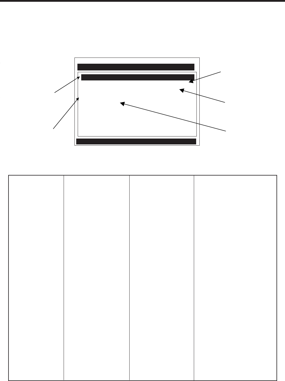
2-11
1010NFM-3J
Section 2
Use this menu to select
a class of liquids and
optionally edit the
following liquid
parameters:
• Estimated Vs
• Viscosity
• Density
(Specific Gravity)
Siemens 2 Channel [1] Channel 1
Select Liquid Class from Liquid Table
UniMass Table Create/Edit Table
Temperature Range -40F to 250F
Pipe Configuration Fully Developed
Anomaly Diams 10
Liquid Class Water 20C/68F
Application Data
The UniMass Table is
used to associate the
metered liquid’s current
temperature and sonic
velocity with its specific
gravity and viscosity.
Use this menu cell to
select an upstream
pipe compensation
correction table.
Use this menu cell
to specify the
temperature range
of the liquid.
Use this menu cell to enter
the number of pipe
diameters between the
upstream configuration and
the transducer installation.
APPLICATION DATA MENU STRUCTURE
Application Data Liquid Class Select Liquid 20% Ethylene Glyclol
50% Ethylene Glyclol
27% CaCl Brine
Water 13C/55F
Water 20C/68F
Water 50C/122F
Water 75C/167F
Water 100C/212F
Water 125C/257F
Water 150C/302F
Water 175C/347F
Water 200C/392F
Water 225C/437F
Water 250C/482F
Acetic Acid
Alcohol
Bromine
Carbon Tet
Chlorine
Diesel Fuel
Gasoline
Glycerine
Kerosene
MEK
Oil (SAE 20)
Sea Water
Toluene
Trichloroethyl
Other
(continued)
The Temperature Range menu cell allows you to specify the expected temperature range at the trans-
ducer mounting location. The default setting: [-400F to 2500F], matches the standard 991 and 1011
series of transducers but not the 1011H. For higher pipe temperatures, selecting the proper tempera-
ture range allows the flow computer to recommend the appropriate transducers.

2-12
1010NFM-3JSection 2
NOTE: The currently active table will be shown highlighted next to the [UniMass Table] menu
cell. If no table is active then [Disable] will appear highlighted next to the [UniMass
Table] menu cell.
NOTE: The [Changing Temp & Vs] lookup table must be serially loaded using the HyperTermi-
nal “Send Text” command. This table can be generated using a utility provided by
Controlotron, which converts the Vs and temperature data into a uniform 10x10 grid
array and formats it appropriately for serial download.
* Must recognize degrees C, degrees F selection.
** Vs, SG and Viscosity must be greater than 0.0. Enable permitted only after table contains at least
two entries of correctly formatted data.
*** Pipe Configuration Default.
APPLICATION DATA MENU STRUCTURE (continued)
Application Data Liquid Class Viscosity cS x.xx (numeric entry)
Density SG x.xxx (numeric entry)
UniMass Table Disabled
Constant Temp Create/Edit Table Table Point New
Vs xx.xxx
S.G. xx.xx
Viscosity (cS) x.xxx
Accept Yes
Clear Pt.
Clear Table No/Yes
Table Active Yes/No
Constant Vs Create/Edit Table Table Point New
Temperature xx.xxx *
S.G. x.xxx
Viscosity (cS) x.xxx
Accept Yes
Clear Pt.
Clear Table No/Yes
Table Active Yes/No
Changing Temp & Vs Table Active Yes/No **
Temp Range -40F to 250F
-40F to 375F
-40F to 450F
Pipe Config Fully Developed***
(Change to Up- 1 Elbow
stream Piping) Dbl Elbow +
Dbl Elbow -
Valve
Expander
Reducer
Norm Entry
Header Inlet
Intrusions
Anomaly Diams xxxx (numeric entry)
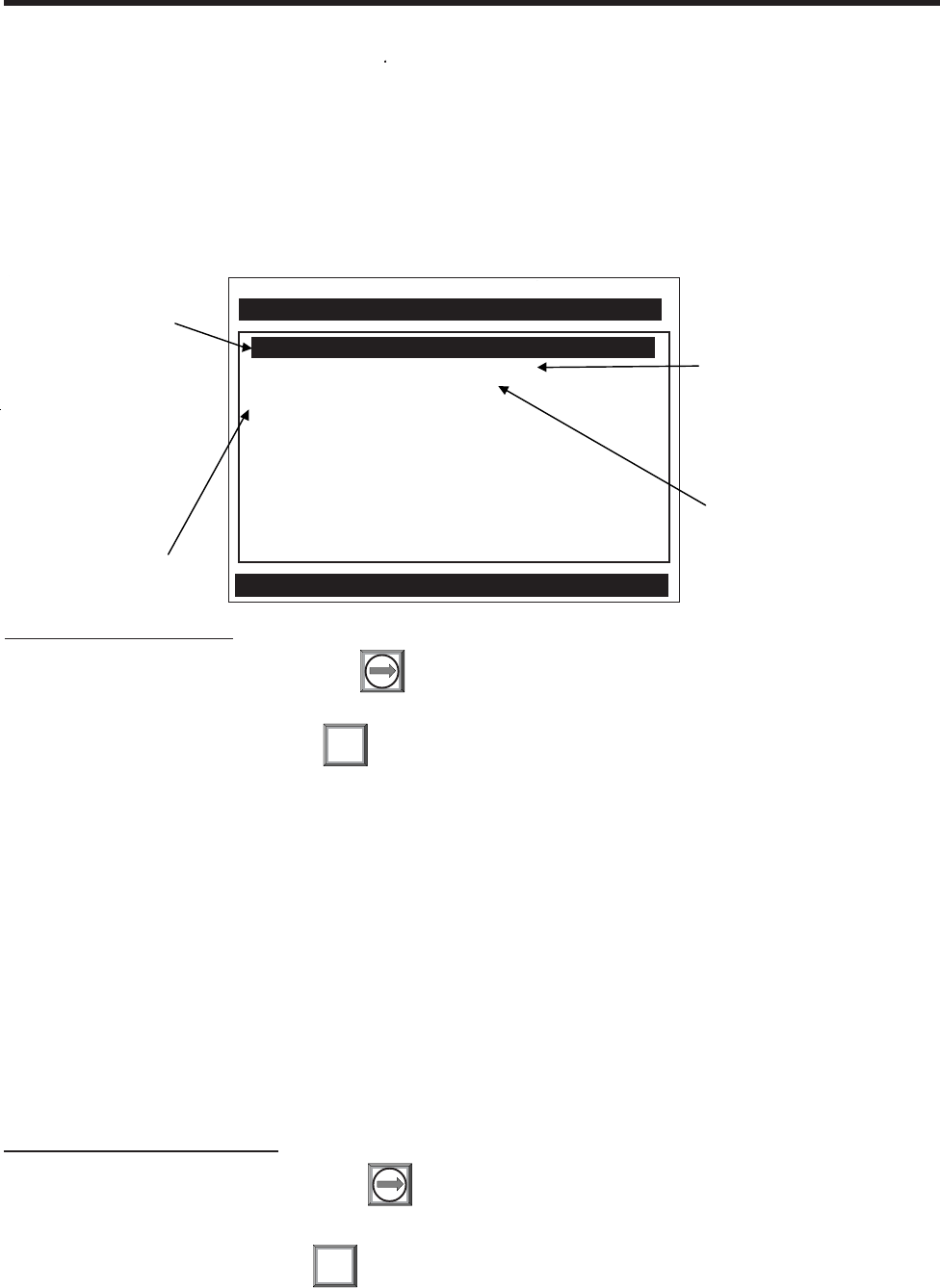
2-13
1010NFM-3J
Section 2
2.3.1 HOW TO SELECT A LIQUID CLASS
The liquids listed in the [Liquid Class] option list are representative samples of the class of liquids to
which they belong. Selecting a named liquid fills in the Estimated Vs (m/s), Viscosity (cS), and Density
(SG) parameters automatically. However, you have the option of editing these parameters individually
to fine tune the liquid settings. If you do not find a liquid that matches your application, then you can
select [Other]. This selection will not provide a liquid name or automatic parameter entry. Only Ethyl-
ene Glycol (20 & 50%), CaCl Brine (27%) and all water entries provide energy metering services.
To select a Liquid Class:
To access the option list press
Scroll through the list to find the closest match to the application’s liquid.
To register selection press ENT
Liquid Class
Siemens Dual Path ABC
Access Liquid Option List
Estimated Vs m/s 1482
Viscosity cS 1.00
Density SG 1.000
Select Liquid Water 20C/68F
Use this menu cell to edit the
Estimated Vs ONLY if you are
sure of a more accurate value.
This will reduce the chances of
a re-spacing request for clamp-
on flow transducers during the
install procedure.
Use this menu cell to edit
the liquid viscosity ONLY
if you are certain that the
data you enter is
accurate. An erroneous
entry could affect meter
calibration.
Use this menu cell
to select a liquid.
Selecting a liquid
automatically enters
data into Liquid
Class menu cells.
Use this menu cell to
edit the specific
gravity of the liquid.
How to Edit the Estimated Vs (liquid sonic velocity)
During transducer installation, the flow computer bases its initial transducer spacing recommendation
on the value stored in this menu cell. Estimated Vs m/s allows you to review and modify (if necessary)
the Vs value for the liquid class you selected.After you install the transducers, the computer will mea-
sure Vs directly. If the displayed (or edited) Vs stored in this menu cell is accurate, the transducers will
be spaced correctly. This will eliminate the need to re-space the transducers after their initial installa-
tion. However, if the estimated Vs is substantially different from the measured value, the computer will
request you to re-space the transducers during the transducer install procedure.
NOTE: During the Xdcr install procedure (see paragraph 2.4), you can ignore a respacing
request by pressing the <Down Arrow> instead of <ENT>. If this triggers a Spacing
Alarm, check [Diagnostic Data/Site Setup Data] to make sure the measured Vs value
does not exceed the Vs max or Vs min items.
To edit the Estimated Vs m/s:
To activate numeric entry press
Type the sonic velocity value using meters-per-second.
To register the data press ENT

2-14
1010NFM-3JSection 2
How to Edit the Viscosity (cS) Setting
The [Viscosity cS] menu cell shows the kinematic viscosity of the selected liquid (in centistokes). The
viscosity value is particularly important for high viscosity liquids. The meter requires an accurate liquid
viscosity to compute the flow profile compensation. If the displayed viscosity is correct, bypass this
menu cell by pressing the <Down Arrow>. Please be aware that the viscosity of the liquid affects the
Reynolds Number compensation applied to the final rate output. Therefore, inaccurate data could
cause flow data errors. Edit this entry only if you know the true viscosity of your liquid. If necessary, our
Technical Service Group can provide reliable viscosity data for most liquids.
To edit the Viscosity setting:
To activate numeric entry press
Use the numeric keys to type the Viscosity value, which must be in centistokes.
To register the data press
How to Edit the Density (SG) Setting
Use the [Density SG] menu cell to edit the nominal specific gravity of the selected liquid. This allows the
flow computer to provide a flow rate output in mass units, if required. This mode suits applications
where the density is not only known, but also fixed, due to well-controlled liquid temperature and chem-
istry. The default specific gravity setting is 1.000. The flow computer uses the liquid’s specific gravity to
form a multiplier for the conversion of volumetric flow to mass flow. Mass flow appears (in selected
units) on the display screen. [Density SG] (as it applies to this system) is defined as the ratio of the
mass of this liquid to the mass of an equal volume of water at 20°C or 68°F.
ENT
To edit the Density SG setting:
To activate numeric entry press
Use the numeric keys to type the Density SG value.
To register the data press
2.3.2 UniMass TABLE
Some 1010 family meters provide a feature we call UniMass. These meters support a UniMass Table
which associates the metered liquid’s current temperature and sonic velocity (Vs) with its specific
gravity and viscosity. These variables are then used to provide mass metering and real-time flow
profile compensation based on Reynold’s numbers. For hydrocarbon liquids requiring standard vol-
ume compensation, a 1010DV flowmeter should be specified.
Note that the UniMass option will provide value to the extent that the table is accurately prepared for
your particular liquid and installed correctly. The table scanning routine can function with as few as two
(completely) defined data points. If the sensed variable(s) assume values beyond the table limits, the
routine does not extrapolate, but rather produces “flat” or “clipped” data, assuming the value of the last
valid table entry.
ENT

2-15
1010NFM-3J
Section 2
The table is built by inputting a series of data points—two inputs and two outputs each:
zInput data consists of sonic velocity (Vs) and temperature.
zOutput data consists of specific gravity (S.G.) and viscosity (cS) at the specified Vs and tem-
perature.
Ideally, each point contains four empirically derived values. However, when enough data exists to per-
mit it, the table editing routine interpolates missing values based on prior user-entered data.
The UniMass feature expands the basic utility of the flowmeter by synergistically combining its ability to
measure sonic velocity and temperature with user-provided data regarding the process liquid or family
of liquids. The resulting instrument is virtually a liquid analyzer, in addition to measuring mass flowrate
and automatically compensating for viscosity variation.
UniMass Table operations are most successfully employed when the application liquids or family of
liquids are fairly well-controlled. Basic table data can be obtained by a variety of means:
zFrom handbooks of physical or chemical data.
zDirectly measured in the laboratory using your 1010, its RTD temperature sensor and a non-
flowing measurement cell (standpipe).
zAfter installation on the process pipe if specific gravity and/or viscosity data regarding the liquid
can be locally obtained via samples or from on-line instrumentation.
Although the UniMass Table is designed to permit both temperature and sonic velocity to be active
input variables, UniMass provides Constant Vs and Constant Temp table editing capabilities as well.
The resulting lookup function then associates specific gravity and/or viscosity with either temperature
or sonic velocity only.
APPLICATION DATA MENU EXPLANATIONS FOR UniMass TABLE
The UniMass Table resides within the Application Data menu, however, in Flow Tube (FT) instruments
it resides within the [Liquid Data] menu.
[UniMass Table] - Press the <Right Arrow> to access the UniMass data point editor.
[Disable] - Press the <Right Arrow> to access tables and enable UniMass routine.
The currently active table will be shown highlighted next to the [UniMass Table] menu cell. If no table is
active then [Disable] will appear highlighted next to the [UniMass Table] menu cell.
[Constant Temp] - Press the <Right Arrow> to access. The [Constant Temp] UniMass Table can be
used for multiple liquid applications with tightly controlled constant temperature or single liquid applica-
tions with varying temperature (ideal if temperature is not measured).
This function simply associates changes in liquid sound velocity with changing SG and Viscosity.

2-16
1010NFM-3JSection 2
zCreate/Edit Table Point [New Point + Points List (1-32)]
You may Create or Edit up to 32 points. If you need support for multiple liquid classes, you may
create additional identical flow sensing sites to accommodate them, altering only the UniMass
Table entries. Then each site may be called up as needed for each liquid.
zVs [Vs Value]
This is the sonic velocity at which the S.G. and Viscosity were measured for this class of liquids.
This data may be obtained from tables of physical constants, measured with your 1010 in a test
cell standpipe while also measuring temperature, or directly measured in the monitored process
line if S.G. and viscosity can also be obtained.
zS.G. [Specific Gravity]
This is the specific gravity of the process liquid at the Vs and Temperature for this table entry. The
specific gravity is defined as the density of the sample divided by the density of water at 20º C (68º F).
zViscosity [Liquid Viscosity (cS)]
This is the viscosity of the process liquid in centistoke units at the Vs and Temperature for this table
entry.
zClear Table [Yes/No]
Use this item to remove all table points. You will need to re-enter all table data if you answer [Yes]
to this menu item.
zTable Active [Yes/No]
Use this item to tell the 1010 meter whether to use the UniMass Table as the source of S.G. and
Viscosity parameters for the currently active site.
[Constant Vs] - Press the <Right Arrow> to access. The [Constant Vs] UniMass Table can be used for
single liquid applications where temperature is directly measured. Availability of liquid properties rela-
tive to temperature greatly simplifies the implementation of this table.
Contains the same menu option list as the [Constant Temp] menu cell above but allows Temperature
input data instead of the Vs (Sonic Velocity).
Alternate Data Entry Method
If you wish, you may input the data table via the meter’s serial port. To accomplish this, the meter must
be in Direct Command Mode (not Menu Mode or Data Display Mode). You can recognize this mode by
noting that the meter responds to a <CR> input with a “? for menu” prompt. The meter will accept a text
file of the correct format into the UniMass table data structure directly.
An example of the format for a four point data file is as follows:
MTABLE 1 4
1510.0 30.0 1.1 2.7
1520.0 40.0 1.5 3.4
1530.0 50.0 1.9 5.5
1540.0 60.0 2.2 6.8

2-17
1010NFM-3J
Section 2
MTABLE is the special keyword indicating that UniMass data follows, 1 stands for the channel
number where the data is being installed, and 4 indicates the number of lines (data points). The
last number must match the number of lines or else the table will not be correctly formed.
Each line corresponds to each point. Sonic velocity is first, followed by temperature (the input
variables). Then comes specific gravity followed by viscosity (the output variables). Do not use
commas between the items, only single spaces. A carriage return is expected after each line,
EXCEPT for the last one.
For example, line 1 of MTABLE 1 4 (1510.0 30.0 1.1 2.7) shown above is read as follows:
1510.0 (Sonic Velocity) 30.0 (Temperature) 1.1 (Specific Gravity) 2.7 (Viscosity)
You may save this file by using a name suggested by the liquid in question. Once the file is saved
use HyperTerminal to send it as a simple text file to the PC serial port of the 1010 flowmeter. It is
suggested that a moderate data rate be used (1200 baud) for this function since the meter is fairly
busy computing and interpolating during the installation of the table.
[Changing Temp & Vs] - Press the <Right Arrow> to access.
The [Changing Temp & Vs] lookup table must be serially loaded using the HyperTerminal “Send Text”
command. This table can be generated using a utility provided by Controlotron, which converts the Vs
and temperature data into a uniform 10x10 grid array and formats it appropriately for serial download.
Below is a sample input data file for gasoline and diesel fuel that was empirically derived from sound
velocity data obtained using a 1010 flowmeter installed on a fuel pipeline. The task of obtaining sound
velocity, as a function of density and temperature, can also be performed in a laboratory environment
under conditions of controlled temperature and liquid properties.
Gasoline and Diesel fuel UniMass input file.
START
-40, 1625, 0.8838, 92.4
-20, 1579, 0.8762, 53
0, 1533, 0.8685, 26
20, 1487, 0.8608, 16
40, 1441, 0.8530, 9.7
-40, 1445, 0.7755, 1.362
-20, 1393, 0.7658, 1.022
0, 1341, 0.7560, 0.83
20, 1289, 0.7460, 0.72
40, 1237, 0.7360, 0.64
END
The file must be in the form shown in the example above, with a START and END keyword to denote
the limits of the data. The data does not have to be sorted in any particular order. A description of the
data can be included at the top of the file since this will be ignored by the 10x10 grid generating pro-
gram.

2-18
1010NFM-3JSection 2
ENT
The four comma separated columns within the data should be formatted in the following order and with
the units indicated:
Column Parameter Units
1 Temperature Deg C or F
2 Sound Velocity (Vs) meters/second
3 Specific Gravity
(relative to water @ 20ºC)
4 Viscosity (kinematic) Centistokes
Once the input data is properly formatted it can then be processed using the PC based UniMass grid
generating program. Follow the instructions included with this program to generate the final grid data,
which can be directly downloaded to the 1010 flowmeter using HyperTerminal “Send Text File” com-
mand.
NOTE: To properly download and direct the UniMass table to the appropriate flowmeter chan-
nel, follow the instructions outlined below:
1. Establish communication with the flowmeter at 9600 baud or less.
2. Disable all channels (select [Channel Disable] menu cell then [Yes]) if they are actively mea-
suring flow.
3. Select the desired default channel for download of the UniMass table. In HyperTerminal type “cv
0” for Channel 1, “cv 1” for Channel 2, “cv 2” for the virtual channel of a dual beam system or “cv
4” for 4-Beam systems.
4. Select the “Send Text File” command from the HyperTerminal menu and proceed to download
the UniMass grid file.
Enable channel operation then select [Table Active] then [Yes] for the Changing Temp & Vs table.
2.3.3 HOW TO SELECT A PIPE TEMPERATURE RANGE
This menu cell informs the flow computer about the expected temperatures that the transducers will be
subjected to during operation. The default setting, -300F to 2250F corresponds with the rated tempera-
ture range of our standard 991 or 1011 series transducers. The other selections provide higher upper
limits of 3750F and 4500F respectively.
If you know that the pipe temperature will exceed 2500F at the transducer mounting lo-
cation, please use this menu cell to select the appropriate range. This will allow the flow computer to
restrict its transducer recommendations to the appropriate environmentally rated types.
To select a temperature range:
To access the option list press
To highlight the desired range press
To register your selection press
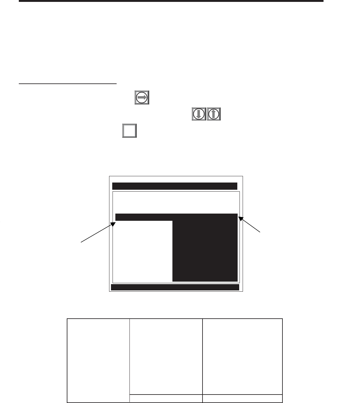
2-19
1010NFM-3J
Section 2
2.3.4 PIPE CONFIGURATION
The [Pipe Configuration] menu cell in the Application Data menu presents a list of descriptions of piping
configurations that could affect the flow profile characteristics (such as “Single Elbow”). Examine the
option list. Selecting a piping configuration that closely approximates conditions at or near your mount-
ing location allows the flow computer to compensate for the effect of upstream piping on flow profile.
The number of diameters between the upstream configurations and the transducer installation can be
numerically entered via the [Anomaly Diams] menu cell.
To select a Piping Configuration:
To access the option list press
To highlight the desired piping configuration press
To register selection press ENT
The default pipe configuration (Fully Developed) wll cause the flowmeter to use the conventional Rey-
nolds Compensation Table when compensating for liquid flow profile behavior.
Application Data Pipe Configuration Fully Developed*
(Change to Upstream 1 Elbow
Piping) Dbl Elbow +
Dbl Elbow -
Valve
Expander
Reducer
Norm Entry
Header Inlet
Intrusions
Anomaly Diams xxxx (numeric entry)
Pipe Configuration Menu Structure
* Default
Siemens Dual Path [1] Path 1
Disignate Pipe Shape Near Transducers
Liquid Class Water 20C/68F
UniMass Table Create/Edit Table
Temperature Range -40F to 250F
Pipe Configuration Fully Developed
Anomaly Diams 1 Elbow
Dbl Elbow +
Dbl Elbow -
Valve
Expander
Reducer
Norm Entry
Header Inlet
Intrusions
Application Data
Use this menu cell to enter the
number of pipe diameters
between the upstream
configuration and the
transducer installation.
Use this menu cell to select
the pipe configuration that
most accurately represents
the upstream pipe condition.

2-20
1010NFM-3JSection 2
2.4 THE PICK/INSTALL XDCR MENU
Use this menu after creating a new site setup in the Channel Setup menu, and defining the pipe
parameters in the Pipe Data menu.
Based on pipe data (and optionally application data) entries, the Pick/Install Xdcr menu automatically
identifies the most suitable transducers for the application. It recommends the appropriate mounting
mode (direct or reflect) and lists the Spacer Bar or Mounting Track part number and spacing index.
Ideally, you will be able to use the primary recommendations. However, you can edit the menu entries
as required to accommodate different transducers or mounting configurations.
The flow computer will adjust its parameters to optimize performance based on your selections. The
Ltn menu cell shows the required spacing distance (in inches or millimeters) between the upstream
and downstream transducers. Use the [Install Completed?] menu cell to inform the flow computer that
you completed the physical mounting of the transducers. You can define the empty pipe and zero flow
values once the transducers are operational.
PIPE CONFIGURATION OPTION LIST DEFINITIONS
Fully Developed Fully Developed flow, as would be expected for very long straight pipe runs
or installation downstream of a flow condition.
1 Elbow Single 90 degree Elbow upstream of transducer installation.
Dbl Elbow + Double out-of-plane Elbows upstream of transducer installation.
Dble Elbow - Double in-plane Elbows upstream of transducer installation.
Valve To Be Determined.
Expander Pipe expansion upstream of transducer installation.
Reducer Pipe reduction upstream of transducer installation.
Norm Entry To Be Determined.
Header Inlet Header or pipe manifold upstream of transducer installation.
Intrusions To Be Determined.
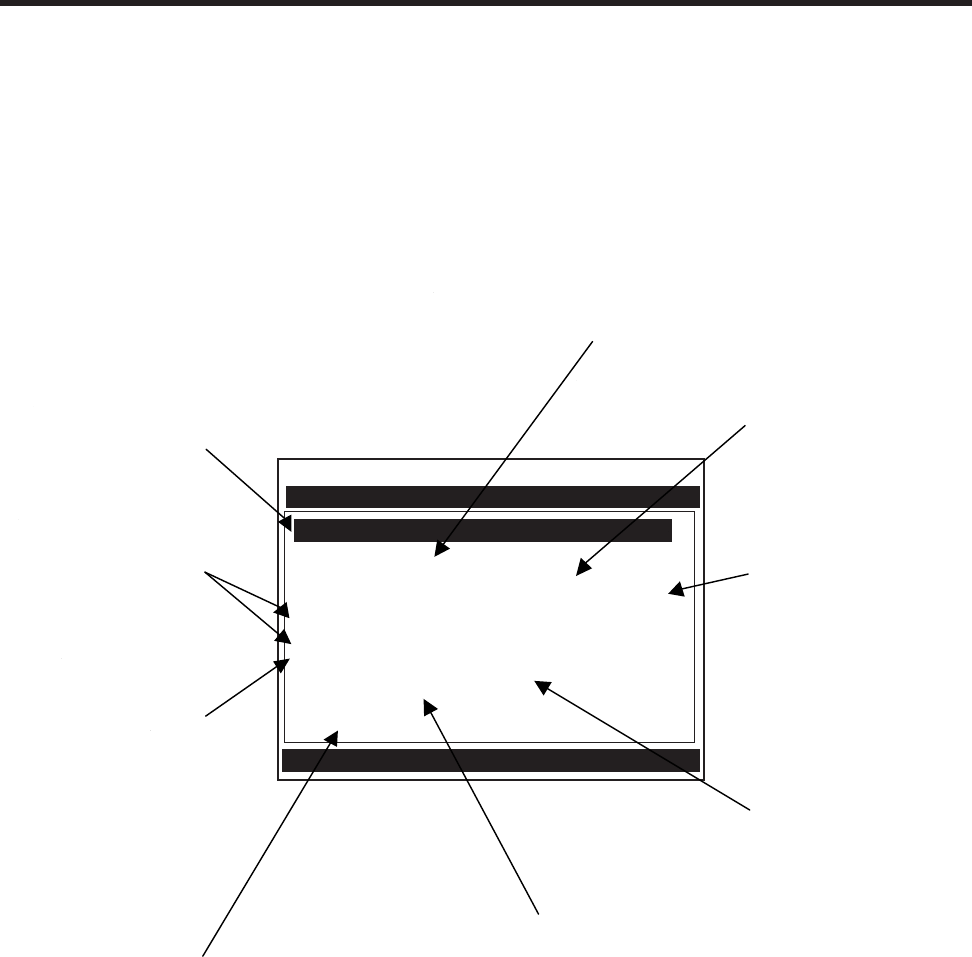
2-21
1010NFM-3J
Section 2
NOTE: Before preceeding to mount transducers, it is recommended that Section 3 - HARD-
WARE INSTALLATION GUIDE be reviewed. Refer to the Pick/Install Xdcr menu and
menu structure shown below for menu cell descriptions and details.
Scroll List and select desired Model
Pick/Install Xdcr
Transducer Model 1011 Universal
Transducer Size B3
Xdcr Mount Mode Reflect
Spacing Offset Spacer Bar PB-1
Number Index 0
Spacing Method Track 1012TAH
Ltn Value (in) 0.565
Install Complete? No
Empty Pipe Set MTYmatic
Zero Flow Adjust Actual Zero
Siemens 2 Channel [1] FLOW1
This menu cell
shows the actual
spacing distance
required between
the transducers.
Use this menu cell to
select the type of
transducer to be
installed.
This menu cell
allows you to select
a mounting mode.
*Use Reflect Mode
whenever possible.
A
fter the transducers are
operating, you can use
this menu cell to
manually set the zero
flow correction.
These menu cells
identify the spacing
indices on the spacer
bar. You must use
these settings to mount
the transducer properly.
This menu cell indicates the
model number of the
appropriate spacer bar for
your transducers and
spacing requirements.
Once you select the
type, use this menu
cell to specify the
transducer size.
Use this menu cell to
inform the meter that you
have completed the
transducer mounting.
After the transducers are
operating, you can use
this menu cell to set the
empty pipe threshold.

2-22
1010NFM-3JSection 2
2.4.1 HOW TO SELECT A TRANSDUCER MODEL
Use the [Transducer Model] menu cell to define the type of transducer for use with your application.
This allows the flow computer to adjust its transmit/receive functions accordingly. You can choose
from either the [1011 Universal] or [1011H High Precision] transducer lists, or from a list of [991 Univer-
sal] models.
You should consider using high precision transducers for extremely critical applications. We usually
recommend these transducers for custody transfer, leak detection or nuclear power applications. The
system default is [1011 Universal]. If this suits the application, bypass this menu cell by pressing the
<Down Arrow>.
Pick/Install Xdcr Transducer Model 991 Universal
1011 Universal
1011 Hi Precision
Transducer Size A1A1 0A0A A1HA1H
A2 0 A2H
B1 1 A3H
B2 2A B1H
B3 2 B2H
C1 3A C1H
C2 3 C2H
C3 4A D1H
D1 4 D2H
D2 5A D4H
D3 5
E1
E2
E3
Xdcr Mount Mode Direct
Reflect
Spacing Offset Minimum
Nominal
Maximum
Number Index 4 (generated)
Spacing Method Spacer Bar [P/N] auto P/N generation
Ltn Value (in) 2.00 (generated)
Install Completed? No [Yes] [Yes] indicates successful install
Install
Install Transfer
Empty Pipe Set MTYmatic
Set Empty
Actual MTY
Zero Flow Adjust AutoZero Reflect mount only
ZeroClr
Reversamatic
Actual Zero
ZeroMatic
1011 Universal 991 Universal 1011H High Precision
PICK/INSTALL XDCR MENU STRUCTURE

2-23
1010NFM-3J
Section 2
To select a Transducer Type:
To access the [Xdcr Type] option list press
To move the cursor to the required transducer model press
To store your selection press
2.4.2 HOW TO SELECT A TRANSDUCER SIZE
When you move the cursor to Transducer Size, the highlighted prompt at the top of the display screen
shows a list of recommended transducer sizes. For example [Recommended Xdcrs:
D3,D2,D1,C1,C3]. The flow computer generates this list automatically based on your pipe and your
application data entries. The left-most transducer size (e.g., D3) is the primary (most appropriate)
choice. The right-most transducer (e.g., C3) is still acceptable (but the least desirable) choice. Since
these are simply recommendations not requirements, you can override the flow computer and use any
size, as long as the mounting method accommodates the pipe’s diameter. The flow computer shows
that your selection is acceptable if it is able to calculate transducer spacing (Ltn).
To select a Transducer Size:
To access the [Transducer Size] option list press
To move the cursor to the desired transducer size press
To select the transducer press
2.4.3 HOW TO SELECT A TRANSDUCER MOUNT MODE
The flow computer recommends the transducer mounting mode [Direct or Reflect]. In almost all cases
it will be Reflect, since this is the most desirable configuration. Reflect mode allows you to mount the
transducers on pipes that do not permit back or side access. Reflect mode provides inherent compen-
sation for flow profile distortion (crossflow) that could be the result of unfavorable application conditions
such as an insufficient upstream straight run. In addition, Reflect mode supports the AutoZero function,
which sets the zero flow velocity automatically.
Direct mounting may produce a stronger transducer signal and requires less mounting length than
Reflect mounting. This can be important if the liquid or pipe material exhibits high sonic attenuation,
thereby preventing operation in the Reflect configuration.
NOTE: We recommend using Direct Mount with Plastic pipes.
To select a Xdcr Mounting Mode:
To access the [Xdcr Mount] option list press
To move the cursor to the required mounting type press
To store selection press
ENT
ENT
ENT

2-24
1010NFM-3JSection 2
2.4.4 REVIEWING THE SPACING METHOD
The flow computer analyzes your transducer selection, mounting mode and pipe size to determine the
best way to install your transducers. It will recommend the use of either a mounting track, a spacer
bar, or independent mounting. The flow computer will list the part number of a mounting track or spacer
bar. If it decides upon independent mounting, it will report the distance required between the two trans-
ducers. In this case, you have to make sure that when you mount the transducers, the space between
them equals the length specified in the Ltn menu cell. See Section 3 for details on how to accomplish
this.
2.4.5 HOW TO USE THE SPACING OFFSET
After you select the mounting method, the flow computer checks your entries for pipe size, transducer
type etc. and then recommends a spacing offset. This is the first step in establishing the correct
distance between the transducers. Spacer bars and mounting tracks utilize number indices (labels) to
simplify transducer placement. One transducer is located at the Reference position, while the other
one is located at the Number Index position. The Number Index cannot be directly edited. However, the
Spacing Offset can be changed via its option list. Changing the Spacing Offset will alter the reported
Number Index. Maximum spacing offset provides moderately greater signal levels but, in some cases,
slightly decreased zero flow stability.
If the flow computer reports “Use Ltn,” you have to measure the distance between the upstream and
downstream transducers. The flow computer issues the actual distance between the transducers in
inches or millimeters (See Ltn). Please consult Section 3 for details on how to use the Ltn measure-
ment. Note that, even though using Ltn does not call for the physical use of the Number Index, you can
still change the Spacing Offset to influence the strength of the transmit signal.
System 1010 uses a pair of precisely matched transducers. Therefore, you can select either one for
the Reference position. You must connect the Up transducer cable to the transducer mounted on the
upstream side of the mounting track. This lets the meter display the flow direction correctly.
It is important that you note each transducer’s serial number and its Index position during the original
installation because to reinstall the flowmeter successfully, you must remount each transducer in its
original position. Transducer pairs have matching serial numbers except for the appended letters “A”
and “B.” This helps you to identify each transducer.
To select a different Spacing Offset
To access to [Spacing Offset] option list press
To move the cursor to the desired offset press
To store selection press ENT

2-25
1010NFM-3J
Section 2
2.4.6 THE NUMBER INDEX MENU CELL
Selecting the Spacing Offset allows the flow computer to calculate the Number Index. The Number
Index establishes the spacing between a pair of transducers. You cannot override this recommenda-
tion. To complete the transducer installation, you must accept the Number Index by mounting the
transducer at that point on your spacer bar or mounting track. Initially, the flow computer bases its
Number Index selection on the pipe diameter and estimated liquid sonic velocity (Vs) you entered in the
Application Data menu. When you invoke the [Install Completed?] routine, the flow computer actually
measures the liquid sonic velocity (Vs). In some cases, it may prompt you to re-space the transducers
to another number index.
2.4.7 THE Ltn MENU CELL
This view only menu cell shows the distance in inches or millimeters between the front faces of the
transducers along the axis of the pipe. If you are mounting the transducers without a track or spacer
bar, you have to space them according to this value (see Section 3 for details). Note that Ltn may be a
negative number for direct mount on very small pipes where the transducer spacing overlaps.
2.4.8 HOW TO USE [INSTALL COMPLETED?]
Use the [Install Completed?] menu cell to inform the flow computer that you have mounted the trans-
ducers according to the selected mode and spacing requirements and are ready to start operation.
To start the [Install Completed?] routine for an original installation:
Select any transit-time mode (e.g., Clamp-On or Flow Tube) and press the <Right Arrow>.
Press <Down Arrow> and scroll to the [Pick/Install Xdcr] menu cell. Press <Right Arrow>.
Install transducers as required (refer to Section 3 for procedures).
NOTES
zMount the transducers using the selected mode (direct or reflect). Please refer to the trans-
ducer mounting procedures detailed in Section 3.
zWhen using a mounting track or a spacer bar in reflect mode, locate the first trans-
ducer at the Reference Index and the second transducer at the recommended Number Index.
zIf you are mounting the transducers independently, you must use the recommended distance;
Ltn to space the transducers.
zYou must use the proper sonic coupling compound. See “Recommended Sonic Coupling
Compounds” in Section 5 for appropriate type and part number.
zThe pipe must be completely filled with a liquid, which can be either flowing or at zero flow.

2-26
1010NFM-3JSection 2
Transducer Model 1011 Universal
Transducer Size B3
Xdcr Mount Mode Direct
Spacing Offset Minimum
Number Index 4
Spacing Method Track 1012TP
Ltn Value (in) 0.217
Install Completed? Yes
Empty Pipe Set Channel Not Setup
Zero Flow Adjust Channel Not Setup
Siemens 2 Channel [1] SITE1
Key [Install] after mounting transducers
Pick/Install Xdcr
Press <ENT>. The [Install Completed?] menu cell will indicate [Yes] after the 1010 is successfully
installed.
NOTE: If the transducers have been installed successfully but the Estimated Vs (sonic veloc-
ity) has been changed, the Pick/Install Xdcr menu cell [Install Completed?] option list
will also display the [Transfer Install] function selection. The Transfer Install function
allows the transducers to be optimally positioned for a different fluid, without the need
for a new Initial Makeup procedure (see the Water Calibration addendum in this manual
for details).
Transducer Model 1011 Universal
Transducer Size B3
Xdcr Mount Mode Direct
Spacing Offset Minimum
Number Index 4
Spacing Method Track 1012TP
Ltn Value (in) 0.217
Install Completed? No
Empty Pipe Set Channel Not Setup
Zero Flow Adjust Channel Not Setup
Siemens 2 Channel [1] SITE1
Key [Install] after mounting transducers
Pick/Install Xdcr
To complete the Install process proceed to page 2-27 and disregard the following paragraphs
explaining the Force Transmit and Force Frequency diagnostic software routines.
After transducers are properly mounted, the flow computer completes its Initial Makeup command and
the [Install Completed?] menu cell appears.
To access the [Install Completed?] option list, press the <Right Arrow>.
Press <Down Arrow> and scroll to the [Install Completed?] menu cell and then press <ENT>
(unless otherwise directed to do so by Controlotron’s Technical Service Department).

2-27
1010NFM-3J
Section 2
Transducer Model 1011 Universal
Transducer Size B3
Xdcr Mount Mode Direct
Spacing Offset Minimum
Number Index 4
Spacing Method Track 1012TP
Ltn Value (in) 0.217
Install Completed? Install
Empty Pipe Set Channel Not Setup
Zero Flow Adjust Channel Not Setup
Siemens 2 Channel [1] SITE1
Drive 11
Pick/Install Xdcr
NOTE: The <ALT> and <MENU> keys must be pressed before the meter scans through all the
drives, or the selection of the detection mode and the Force Transmit function must
be initiated again.
1. After [Install] is selected press <ENT>. While the flowmeter is going through the drives (see menu
screen below), press the <ALT> and <MENU> keys simultaneously.
2. A typical menu screen will appear as shown below and indicate the current ALC (e.g., 50).
This ALC number indicates the current receive signal strength and can be used for further diagnos-
tic purposes.
Transducer Model 1011 Universal
Transducer Size B3
Xdcr Mount Mode Direct
Spacing Offset Minimum
Number Index 4
Spacing Method Track 1012TP
Ltn Value (in) 0.217
Install Completed? Install
Empty Pipe Set Channel Not Setup
Zero Flow Adjust Channel Not Setup
Siemens 2 Channel [1] SITE1
ForceN fx=8 m=7 ALC=50
Pick/Install Xdcr
Force Transmit Procedure
This diagnostic software routine allows the user to “force” a transmitting condition that can be use to
search for an amplitude level (ALC) when Detection Fault or Low Signal alarms are present. The
routine forces the flowmeter to generate constant transmit bursts while reporting current receive signal
strength for the user. To initiate the Force Transmit function, refer to the example shown below.
Transducer Model 1011 Universal
Transducer Size B3
Xdcr Mount Mode Direct
Spacing Offset Minimum
Number Index 4
Spacing Method Track 1012TP
Ltn Value (in) 0.217
Install Completed? Install
Empty Pipe Set Channel Not Setup
Zero Flow Adjust Channel Not Setup
Siemens 2 Channel [1] SITE1
Pick/Install Xdcr
Detection Fault
Press [ENT]
Siemens 2 Channel [1] SITE1
Transducer Model 1011 Universal
Transducer Size B3
Xdcr Mount Mode Direct
Spacing Offset Minimum
Number Index 4
Spacing Method Track 1012TP
Ltn Value (in) 0.217
Install Completed? No
Empty Pipe Set Channel Not Setup
Zero Flow Adjust Channel Not Setup
Key [Install] after mounting transducers
Pick/Install Xdcr

2-28
1010NFM-3JSection 2
Immediately after you press <ENT>, the computer starts an internal process called an Initial Makeup.
The current Initial Makeup activity, for example: Drive 14 m 10 [—] appears at the top of the display
screen. During the Initial Makeup, the flow computer verifies your site data, records the sonic charac-
teristics of the pipe and liquid and then adjusts internal parameters to optimize flow measurement.
Please remain patient. This process can take several seconds or several minutes to complete. There
is no relationship between the length of an Initial Makeup and the meter’s subsequent performance. An
Initial Makeup for larger pipes (and more demanding application conditions) simply takes a little longer.
Upon sucessful completion of the initial makeup, the 1010 will show you a pop-up window with the
measured Vs as shown below.
This means that the flow computer was able to complete the Initial Makeup and is now actively mea-
suring flow. This pop-up window allows you to “fine-tune” the Measured Vs by pressing the <Right
Arrow> to activate numeric entry. You can then use the numeric keys to type a different value. How-
ever, only edit the Measured Vs when you are certain of your liquids actual sonic velocity. If, however,
there is a large discrepancy between the “measured” Vs and the “actual” Vs, then consider that an
accurate Vs measurement depends on certain parameters that the flow computer cannot sense di-
rectly (e.g., pipe dimensions or transducer placement). In other words, entering incorrect pipe param-
eters or not using the recommended spacing could result in an erroneous Vs measurement.
The meter is now ready to report flow. Press the <MENU> key to display flow.
In cases where the actual Vs differs noticeably from the estimated Vs, the computer may issue a re-
space command. This requires that you re-space the Number Index transducer at the new Number
Index, then press <ENT> again. Repeat the initial makeup process. You can override a re-space
command by simply keying the [Down Arrow]. However, after the meter completes operating, you
must confirm that the sonic velocity (Vs) of the liquid falls between the [Vs max] and [Vs min] items in
[Diagnostic Data/Site Setup Data].
Therefore, only consider editing the measured Vs after you remove all the primary causes for an
inaccuracy. Check your pipe dimensions and pipe material entries. Re-check the transducer spacing
and part numbers. Large Vs discrepancies are almost always due to erroneous pipe data or incorrect
transducer placement.
Measured Vs m/s
1470
3. To exit Force Transmit, press the <Left Arrow> and a Detection Fault prompt will appear (see
above). Press the <Left Arrow> again and the meter will return to the Pick/Install Xdcr menu and
highlight the [Empty Pipe Set] menu cell.
4. To force a frequency, repeat steps 1 and 2 above, but press <Ctrl> and <MENU>. The following
typical pop-up prompt will appear:
Using the numeric keys enter the desired drive code and press <ENT>.
5. If the Force Transmit diagnostic procedure is not used, the normal [Install Completed?] function
occurs as follows:
To complete the Install process after mounting the transducers press <ENT>.
Drive
=0
2-29
1010NFM-3J
Section 2
If you want to redo the Initial Makeup, move cursor to [New Makeup], then press <ENT>. This resets
the option list. You can now repeat the install routine described previously.
2.4.9 THE EMPTY PIPE SET MENU
The flow computer performs the MTYmatic routine automatically during its Initial Make-up to establish
a standard setting for the Empty Pipe alarm. The Empty Pipe Set option list allows you to re-invoke
MTYmatic, use an Actual MTY routine (if application conditions allow you to empty and refill the pipe) or
use the Set Empty routine to set the empty pipe threshold by direct numeric entry.
How to Use the Actual MTY Command
If application conditions allow you to empty and refill the pipe, then you should perform the Actual
Empty procedure. This is the recommended way to define the empty pipe threshold.
NOTE: NEVER perform this procedure when the pipe is full.
To perform the Actual MTY Procedure:
To access the [Empty Pipe Set] option list press
To move the cursor to [Actual MTY] press then
Empty the pipe completely, then press .
appears on the menu prompt line.
Refill the pipe completely, then press .
To accept the Measured Vs:
Press or moves the cursor to the [Empty Pipe Set] menu cell.
If you decide to edit the Measured Vs:
To activate numeric entry press
Use the numeric keys to type the new Vs value (in meters-per-second).
To store the corrected Vs press
The flow computer may recommend a new Number Index and prompt you to press
Remount the transducer at the new Number Index.
ENT
ENT
To repeat the Initial Makeup process press
After the flow computer completes its Initial Makeup command, the [Install Completed?] option list
changes to:
appears on the menu prompt line.
ENT
ENT
ENT
ENT
[Empty Pipe Press Enter]
[Fill Pipe Press Enter]
Install Completed? Yes
New Makeup

2-30
1010NFM-3JSection 2
How to Use the MTYmatic Command
You can repeat MTYmatic (performed during the Initial Makeup) to correct an inaccurate Actual MTY
setting if conditions do not allow you to repeat the Actual Empty procedure.
NOTE: Only use the MTYmatic procedure when the pipe is full.
To start MTYmatic:
To access the [Empty Pipe Set] option list press
Move the cursor next to [MTYmatic] press
To invoke MTYmatic press ENT
How to Use the Set Empty Command
Use [Set Empty] to enter a number that represents the signal strength level consistent with an empty
pipe. [Set Empty] uses non-linear scaling. There is no direct correlation between the number you enter
and any standard amplitude unit. If you set the number too low, the meter may not detect a true empty
pipe. If you set it too high, it could trigger the empty pipe alarm, suspending flow measurement, even
though the liquid is flowing.
To enter an Empty Pipe Alarm Threshold:
To access the [Empty Pipe Set] option list press
To move the cursor to [Set Empty] press
Press . The current empty threshold number appears in a pop-up window.
Use the numeric keys to type a new Set Empty number.
To store the Set Empty number press
2.4.10 ZERO FLOW ADJUST MENU
Unlike turbine meters ultrasonic transit-time meters provide active flow measurement right down to
zero flow, however, the measurement of the transit-time delta is dependent on the similarity or “match”
of the electronics, cables and ultrasonic transducers. Consequently some flow offset (or zero offset)
may be present in any installation. To eliminate this residual zero offset Controlotron has developed
several different methods to insure proper zero flow compensation. The following paragraphs de-
scribe each method and when they should be used.
AutoZero
When the 1011 transducers are mounted in the Reflect Mode configuration (see paragraph 3.1.5) the
AutoZero routine is automatically invoked at the end of the Initial Makeup. Flow does not have to be
stopped to perform AutoZero since only the pipe wall signal is used in determining the zero offset and
not the liquid component. The AutoZero routine performs a one-time analysis of the pipe wall compo-
nent of the ultrasound signal to quantify any residual mismatch in the hardware. Once the AutoZero
routine is complete, the system memorizes this measured zero offset and subtracts this value from
the flow reading.
ENT
ENT

2-31
1010NFM-3J
Section 2
Actual Zero
The “Actual Zero” function simply averages the indicated “zero flow” readings (over a user defined time
period) then stores this average value in memory. Under normal operation the indicated flow reading is
zero compensated by simply subtracting this memorized value from the uncompensated flow reading.
Actual Zero is the most positive method for zeroing the system, however, flow must be stopped with the
line blocked (if possible) before invoking this function. If stopping flow is not possible then an alternate
zeroing method should be selected.
ReversaMatic
This routine involves swapping the UP and Down transducers on the pipe (while keeping the cables
attached) such that the difference in the transit-time change represents the zero offset. The fixed zero
offset value is stored in memory in the same manner as described in Actual Zero. This routine would
generally be used whenever flow cannot be stopped and the transducers cannot be mounted in the
Reflect Mode configuration. Flow must be stable during the entire process.
ZeroMatic (not present in MultiPulse operation)
When ZeroMatic is invoked the flowmeter first performs the same analysis as described above in the
AutoZero routine. However, after this analysis is complete the flowmeter continues to interrogate the
pipe wall signal and update the zero offset value under normal operation, such that the flowmeter
dynamically compensates for changing conditions which would normally result in zero drift. ZeroMatic
will only operate with the transducers mounted in the Reflect Mode configuration and is recommended
for applications which experience large temperature extremes.
NOTE: Invoking ZeroMatic will clear any existing “fixed” or memorized zero offset. If any zero
offset remains after flow is stopped, an Actual Zero can be performed without inter-
rupting ZeroMatic operation. To disable ZeroMatic, invoke it again, but then press <Left
Arrow> to abort the installation.
NOTE: The ZeroClr command only resets the memorized zero offset registers not those set
when the AutoZero routine is invoked.
NOTE: Flow must be stopped with the line blocked (if possible) before invoking this function.
To invoke Actual Zero:
Access the [Zero Flow Adjust] option list by pressing
ENT
ENT
Press . A pop-up window prompts you to set the current flow rate (in selected
rate units) to equal zero (0.000).
NOTE: If a flow offset is desired (i.e., to test analog outputs) then press <Right Arrow> to
enable numeric entry.
Press to start the Actual Zero process.
Using Actual Zero

2-32
1010NFM-3JSection 2
Important Note: A caution on the use of upper and lower flow limits (used to prevent flow mis-registra-
tion) prior to using the Reversal Zero technique (Reversamatic): If the negative flow rate that the meter
reads in the step during which the transducers are reversed is more negative than the lower flow limit,
the meter will re-register positive and the Reversal Zero cycle will thus be corrupted.
Therefore, postpone the installation of upper and lower flow limits until the reversal zero procedure is
executed successfully. For pipes that combine large diameters with very high flow velocities, it may be
necessary to move the upper and lower flow limits out of the way until the reversal zero is completed.
Moreover, pipes of this size frequently have excellent intrinsic zero performance and may not even
need zeroing.
When you send the command, the flow computer analyzes the current flow rate for up to sixty sec-
onds, integrating (averaging) the data for the best zero correlation. During this time, the menu prompt
at the top of the display screen shows a timer that counts from zero to sixty. You can allow zero
averaging for the entire period, or cancel the process at any time by pressing the <ENT> key. This
controls the amount of data the meter averages to obtain a zero level.
Using ReversaMatic
If site conditions do not permit stopping the flow rate at the mounting location, and Reflect Mount is not
possible, then use the ReversaMatic routine to establish the zero flow level.
To invoke ReversaMatic:
zTo access the [Zero Flow Adjust] option list press
zMove the cursor to [ReversaMatic]. Press to invoke the routine.
zThe meter begins to measure the positive flow rate. “Positive” flow refers to flow moving from
upstream transducer location to the downstream transducer location. Note top prompt line shows:
Reversamatic Action
zUpon completion, the meter beeps and the display screen shows:
Reverse Xdcrs / Press ENT.
zNow remove then remount the upstream and downstream transducers in their reversed positions.
Mount the Up transducer (without removing its cable) in the Down transducer/cable location. Mount
Down transducer with its cable in the Up transducer/cable location. When remounting the trans-
ducers, couple them to the pipe properly. Press <ENT> (after re-installing the transducers).
zThe flow computer measures the negative flow rate briefly, then beeps and repeats the
Reverse Xdcrs / Press ENT prompt.
zNow remount the transducers for normal operation (in their original orientation). When remounting
transducers, couple them to the pipe properly. Press <ENT> (after re-installing the transducers).
This completes the ReversaMatic procedure. The system’s zero accuracy will be very close to that
obtainable using the Actual Zero method, providing flow remained constant during this procedure.
ENT
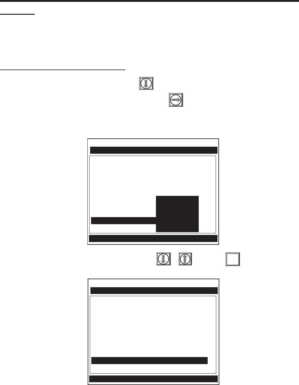
2-33
1010NFM-3J
Section 2
Select the [ZeroMatic] menu cell by pressing or then press
ZeroMatic (optional function) REYNOLDS TABLE
NOTE: ZeroMatic is used in the Reflect Mode only. Invoking ZeroMatic clears any existing
fixed zero offset.
Use this menu cell to select the ZeroMatic option. If conditions permit the use of the Auto Zero function
then the ZeroMatic option can be used as well.
To select and enable the ZeroMatic option:
In the Pick/Install Xdcr menu, press to scroll to the [Zero Flow Adjust] menu cell.
To access the [Zero Flow Adjust] option list press
NOTE: If ZeroMatic is not running, the [Actual Zero] menu item will be displayed next to the
[Zero Flow Adjust] menu cell.
ENT
When the initial makeup of ZeroMatic is complete the screen will return to the Pick/Install Xdcr menu
and automatically highlight [Operation Adjust], which is the next menu cell.
Siemens 2 Channel SITE1
Transducer Model 1011 Universal
Transducer Size B3
Xdcr Mount Mode Reflect
Spacing Offset Minimum Flow
Number Index 7
Spacing Method Track 1012TP
Ltn Value (in) ReversaMatic
Install Completed? ZeroMatic
Empty Pipe Set Auto Zero
Zero Flow Adjust Actual Zero
ZeroClr
Conforms Indicated flow to Actual Zero
Pick/Install Xdcr
Siemens 2 Channel SITE1
Transducer Model 1011 Universal
Transducer Size B3
Xdcr Mount Mode Reflect
Spacing Offset Minimum Flow
Number Index 7
Spacing Method Track 1012TP
Ltn Value (in) 0.778
Install Completed? Yes ZeroMatic
Empty Pipe Set Channel Not Setup
Zero Flow Adjust ZeroMatic
ZeroMatic Active [6:.................:0]
Pick/Install Xdcr

2-34
1010NFM-3JSection 2
Channel/Path Setup
Pipe Data
Application Data
Pick/Install Xdcr
Operation Adjust
Flow/Total Units
Data Span/Set/Cal
Stripchart Setup
Datalogger Setup
I/O Data Control
Diagnostic Data
Siemens 2 Channel SITE 1
Dual Channel Flow
Conforms operation to user Preferences
To disable the ZeroMatic function:
Select the [Pick/Install Xdcr] menu cell from the Dual Channel Flow menu.
Scroll down to the [Zero Flow Adjust] menu cell by pressing
NOTE: The highlighted [ZeroMatic] menu item is the only indication that ZeroMatic is function-
ing.
Invoke the ZeroMatic initial makeup procedure as previously described above.
While ZeroMatic initial makeup is running, press to abort the process thereby disabling the
function.
The screen will return to the Dual Channel Flow menu and highlight the [Operation Adjust]
menu cell.
2.5 THE OPERATION ADJUST MENU
This menu becomes available after picking a meter type and measurement channel. We recom-
mend that you use it after the transducers are installed and operating to “fine-tune” the meter’s
output characteristics.
Each application presents different data display and output requirements due to unique pipe and liquid
conditions. Use the Operation Adjust menu to match meter operation to the site. You can set damping
controls for the primary flow rate output. You can define a Deadband, (usually a very low flow rate),
below which, the flow output will be forced to zero. You can also select the meter response to a
continuous Fault condition.
Siemens 2 Channel [1] BCD
Determine Fault Memory Delay
Operation Adjust
Damping Control Smart Slew
Deadband Control 0.000
Memory/Fault Set Memory
Memory Delay <sec> 120
Reflexor Zero/Fault Set Fault
Use this menu cell to
select either
SmartSlew™ or Time
Average output
damping.
Use this menu cell to
select meter response
to a fault condition.
Fault drops outputs to
zero. Memory retains
last valid reading for
duration of Memory
delay.
Use this menu cell to enter
the duration (in sec.) that you
want the meter to maintain its
last reading for during a fault
condition. The hidden cell
only appears if you select
[Memory Mode].
Use this menu cell to
change the Reflexo
r
response to a Zero
Fault indication b
y
selecting [Zero] in the
[Zero/Fault Set] menu.
.
Use this menu cell to
enter a flowrate
deadband threshold.
Flowrates below this
level will be reported
as zero flow.
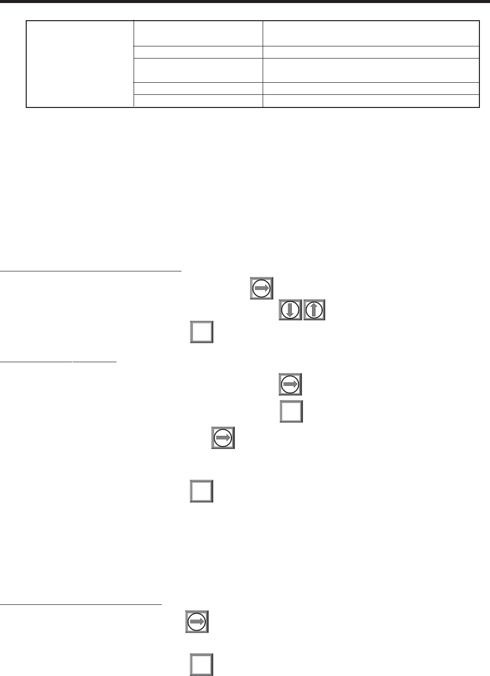
2-35
1010NFM-3J
Section 2
2.5.1 DAMPING CONTROL
System 1010 provides two different data output filter types, SmartSlew and Time Average (recom-
mended). SmartSlew provides the best combination of data smoothing and quick response to sudden
rate changes. It performs data scatter damping during steady flow periods while maintaining the ability
to respond instantaneously to changing flow rates. SmartSlew values range from [1 to 9]. The default
is [6]. Pick a higher number to slow meter response to a rate change. Time Average integrates the
instantaneous flow rate over a selectable time period. You enter a value (in seconds), which sets the
time it takes the meter to respond to a rate change. The default is 10 seconds. Enter any amount of
time up to 60 seconds maximum.
To edit the default SmartSlew setting:
To access the [SmartSlew] option list press three times.
Scroll the numeric list to the desired choice press
To register the new value press
To select Time Average:
To access the [Damping Control] option list press
To move the cursor down to [Time Average] press
To enable Time Average entry press
Use the numeric keys to type the new Time Average setting.
To register the new value press
2.5.2 DEADBAND CONTROL
Use Deadband Control to instruct the meter to report zero flow if the flow rate falls below a specified
level (usually a very low rate). It will prevent the possibility of data scatter (a natural result of digital
computation) from causing false totalizer accumulation during long non-flowing periods. Inspect the
actual data scatter during zero flow conditions to find the proper deadband setting for your application.
To edit the default setting (0.000):
To enable numeric entry press
Use the numeric keys to type in the desired rate (using selected flow rate units).
To register the new value press
ENT
ENT
ENT
ENT
Operation Adjust Damping Control Smart Slew x (numeric selection)
Time Average xx.x (numeric entry)
Deadband Control x.xx (numeric entry)
Memory/Fault Set Memory
Fault
Memory Delay (sec) xxx (numeric entry) (hidden in Fault Mode)
Reflexor/Zero/Fault Set Fault/Zero (Reflexor Mode only)
OPERATION ADJUST MENU STRUCTURE

2-36
1010NFM-3JSection 2
2.5.3 MEMORY/FAULT SET
Certain situations (e.g., an empty pipe or excessive aeration) will interrupt data production. Use Memory/
Fault Set to select the meter response to such an interruption. The Fault setting (default) will zero the
flow rate output and declare an alarm on a flow display screen, Datalogger report and an assigned
relay output.
For some applications, occasional temporary Fault conditions may be a normal part of the process
and would not require an alarm response. The system offers a Memory operating mode to support
such an application. Memory Mode suspends the system’s Fault response by preventing the flow
outputs from dropping to zero for the interval specified in the [Memory Delay] menu cell. During the
Memory duration, the meter will maintain the last valid flow reading measured before the onset of the
fault condition. The default Memory Delay is 60 seconds. You may select any duration from 3 to 604,800
seconds (one week).
To select Memory mode:
To access the [Memory/Fault Set] option list press
Move the cursor down to [Memory] by pressing
To make selection press
This moves the highlight to Memory Delay (sec).
Memory Delay (sec)
Selecting [Memory] activates the suppressed Memory Delay menu cell. It allows you to specify the
number of seconds that the meter maintains its last valid flow reading. When the memory delay ex-
pires, it triggers the fault alarm response described previously.
To specify the Memory Delay:
To enable numeric entry press
Use the number keys to type the delay in seconds.
To register the new value press
2.5.4 REFLEXOR ZERO/FAULT SET OPTION (Reflexor Mode only)
NOTE: The [Zero/Fault Set] menu option only appears on the display if the selected Channel
is the Reflexor mode.
The System 1010 Reflexor declares a Fault when the receive signal drops below the Doppler detection
threshold. To change the Reflexor response to a Zero Flow indication rather than a Fault, select [Zero]
in the [Zero/Fault Set] menu option. Note the following:
a. FAULT – When selected the system will declare the Reflexor channel to be in Fault and the
flowmeter will indicate “F” on the display screen. Note that when a new Reflexor channel is created
the [Fault] option is the default mode. Also note that the sum (or difference) channel will also be
declared to be in Fault.
b. ZERO – When selected the Reflexor channel will be declared to be at Zero Flow instead of in
Fault and the flowmeter will indicate 0.00 on the display screen.
ENT
ENT

2-37
1010NFM-3J
Section 2
2.6 THE FLOW/TOTAL UNITS MENU
The Flow/Total Units menu is available after selecting a meter type and measurement channel. Use the
Flow/Total Units menu to select volumetric flow units and an associated time base for the energy and
flow rate and total outputs. After making your selections, a view-only menu cell shows the resultant
scaling. Another menu cell lets you adjust the output resolution by selecting a display range.
This system provides three totalizer display modes:
POSFLOW Positive (forward)/flow total only
NEGFLOW Negative (reverse)/flow total only
NETFLOW The net of the Positive and Negative/flow (default)
Invoking the NOTOT command disables the Totalizer. To-
talization will not resume until you repeat the Fn and Nu-
meric 2 key sequence. When you activate NOTOT, an N
precedes the TOTAL symbol (i.e., [NTOTAL]) on the LCD
Screen.
*Use the <F1> key as the “Lead-in command” for 4-Path Totalizer operations.
The LAPTOT command freezes the Totalizer screen
display. However, the flow computer will continue to up-
date its internal registers. The flow computer will show the
current total when you repeat the F1-Numeric 3 key se-
quence. When you activate LAPTOT, an L precedes the
TOTAL symbol (i.e., [LTOTAL]) on the LCD Screen.
Clears the Batch Sample totalizer register. See Batch/
Sample Tot.
CLEAR
TOTALIZER CONTROLS (the ‘n’ in <Fn> = channel number)*
(Makeup Latch)
(Totalizer snapshot)
(Totalizer Freeze)
Resetting the Totalizer registers clears all total data ac-
cumulated during operation.
NOTE: In Dual-Beam mode, the Totalizer operates only on
the virtual system channel (Ch 3). Therefore in this case,
the CLEAR trigger would be <F3> <1>.
NOTOT
(also clears overflow)
F1
F2
F3
F4
6
F1
F2
F3
F4
4
F1
F2
F3
F4
3
F1
F2
F3
F4
2
F1
F2
F3
F4
1
Clears the Makeup Latch. See paragraph 2.7 The Data
Span/Set/CAL Menu and subparagraph 2.7.1 Span Data.
CLEAR
(Batch/Tot Register)
CLEAR
LAPTOT

2-38
1010NFM-3JSection 2
THE FLOW/TOTAL UNITS MENU STRUCTURE
Flow/Total Units Volume Units Flow Volume Units Gallons (US)
Liters
Cubic Feet
Cubic Meters
Cubic Inches
Cubic Cm
Ounces (U.S.)
Imperial Gal
31.0 GAL BBL
31.5 GAL BBL
42.0 GAL BBL
55 GAL Drum
Acre-feet
Pounds
Kilograms
Tons
Metric Tons
Ft/Sec (Vel)
M/Sec (Vel)
Flow Time Units MIN
HR
DAY
SEC
Flow Display Range Autorange
High
Flow Display Scale mGAL/MIN
GAL/MIN
KGAL/MIN
Total Volume Units Same list as
Flow Volume Units
Totalizer Scale GAL
KGAL
MGAL
Total Resolution 000X0000
0000X000
00000X00
Totalizer Mode NEGFLOW
NETFLOW
POSFLOW
Batch/Sample Total x.xxx (numeric entry)
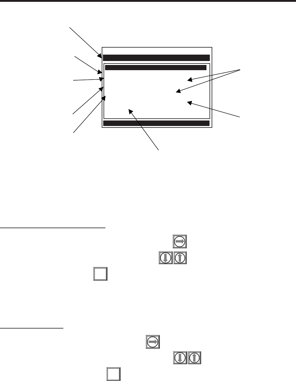
2-39
1010NFM-3J
Section 2
2.6.1 FLOW VOLUME UNITS
The [Flow Volume Units] option list allows you to select the rate units the meter uses to report volumet-
ric or mass flow. If you select mass units, the meter uses the specific gravity parameter (see Applica-
tion Class section) to convert volumetric flow to mass flow. The default English Units is [Gallons].
To select a Volumetric or Mass Unit:
To access the [Flow Volume Units] option list press
To move the cursor to the required units press
To store selection press
2.6.2 FLOW TIME UNITS
The [Flow Time Units] option list allows you to select a flow display time base. The system default is
[Minutes]. If this suits the application, press the <Down Arrow> to bypass this menu cell.
To select a Time Unit:
To access the [Time Unit] option list press
To move the cursor to the required time units press
To store the time units press
ENT
ENT
Flow Volume Units Gallons <US>
Flow Time Units MIN
Flow Display Range Autorange
Flow Display Scale GAL/MIN
Total Volume Units Gallons <US>
Totalizer Scale KGAL
Total Resolution 00000x00
Totalizer Mode NETFLOW
Batch/Sample Total 0.000
Siemens 2 Channel [1] FLOW1
Choose desired Flow rate volume units
Flow/Total Units
Use this menu cell to enter a
volume accumulation for the
batching or sampling totalizer
relay trigger.
Use these menu cells
to set the scaling for the
flow rate and flow total
outputs.
Use this menu cell to
select how the totalizer
accumulates flow.
Use this menu cell to set the
resolution of the totalizer.
Use this menu cell to select
either volumetric or mass flow
total units.
Use this menu cell to select a
range for the flow rate displa
y
screen.
Use this menu cell to select a
time base for the flow rate
units.
Use this menu cell to select
either volumetric or mass flow
rate units.

2-40
1010NFM-3JSection 2
2.6.3 FLOW DISPLAY RANGE
The [Display Range] option list offers a choice of Autorange (default), or High Range. The Autorange
selection increases resolution automatically at low flow rates and reduces resolution at high flow rates
as required to prevent data overflow. If you select Hi range, the meter controls its screen resolution to
prevent data overflow at the highest possible flow.
To edit the Display Range:
To access the [Display Range] option list press
To move the cursor to the required display range press
To store selection press
2.6.4 FLOW DISPLAY SCALE
After you select rate units, the meter automatically computes a prefix to provide the best combination of
capacity and resolution (e.g., KGAL/MIN). The [Flow Display Scale] menu cell shows the results. If the
displayed scaling is not suitable, you can edit it by accessing the option list. Note that this scaling
applies to all flow rate data displayed on the flow display screen, even if the units do not appear next to
the data (because there may not be room on the screen). Therefore, always keep this prefix in mind
when you enter flow related data.
To select a different Flow Display Scale:
To access the [Flow Display Scale] option list press
Move the cursor to the desired display scale by pressing
To register selection press
2.6.5 TOTAL VOLUME UNITS
This menu cell allows you to select which units the meter uses for the flow total output. If you select
mass units, the meter uses the specific gravity parameter (see paragraph 2.3) to convert volumetric
flow to mass flow. The default English Flow Total Units is [Gallons] (US). If this suits the application,
press to bypass this menu cell.
To change the default setting:
To access the [Total Volume Units] option list press
To move the cursor to the desired Total volume units press
To store selection press ENT
ENT
ENT

2-41
1010NFM-3J
Section 2
2.6.6 TOTALIZER SCALE
After you select totalizer units, the meter automatically computes a prefix to provide the best combina-
tion of capacity and resolution (e.g. MGAL/MIN). The [Totalizer Scale] menu cell shows the results. If
the displayed scaling is not suitable, you can edit it by accessing the option list. Note that this scaling
applies to all flow total data displayed on the flow display screen, even if the units do not appear next to
the data (because there may not be room on the screen). Always keep this prefix in mind when you
enter totalizer-related data.
To select a different Totalizer Scale:
To access the [Totalizer Scale] option list press
Move the cursor to the desired display scale by pressing
To register selection press
2.6.7 TOTAL RESOLUTION
The meter assigns multiplier prefixes for the flow total units you selected (e.g., MGPM). It provides
three resolution (or capacity) levels. Therefore, actual Totalizer display units depend on the selected
multiplier. Check the total units by accessing the [Totalizer Scale] menu cell.
If you use the totalizer (TOTCNT) relay output, take into account:
a) The TOTCNT relay output pulses at a maximum rate of .5 pulses per sec. (.5 Hz).
b) The meter sends a totalizer output pulse for every advance of the rightmost visible
totalizer digit.
It is possible for a high flow rate to persist long enough to exceed the relay output’s .5 Hz rate. If this
occurs, the meter will store excess pulses in an overflow buffer, and route them back to the relay when
the flow rate drops enough to allow the TOTCNT output to catch-up. Exceeding the .5 Hz rate for long
periods could cause an excessive accumulation of buffered pulses and continue to trip the relay after
the flow rate lessens, or even stops. If this occurs, the meter will be unable to indicate the current flow
total. Therefore, select a resolution to ensure that, even at the maximum expected flow rate, the TOTCNT
pulse will not be activated more than .5 times per second for any appreciable length of time. Note that
resetting the Totalizer also clears the overflow buffer.
To change the default resolution:
To access the [Total Resolution] option list press
Move the cursor to the required resolution by pressing
To store selection press ENT
ENT
2-42
1010NFM-3JSection 2
NETFLOW (default) is best for applications where there may be zero flow for long periods. It mini-
mizes false Totalizer register increments due to data scatter. Press the <Down Arrow> to accept the
default setting.
To select a Totalizer Mode:
To access the [Totalizer Mode] option list press
Move the cursor to the required Totalizer mode by pressing
To store selection press
2.6.9 BATCH/SAMPLE TOTAL
The meter maintains a separate totalizer register for Batching or Sampling applications. Unlike the
Flow Total registers, you cannot access this register directly. It is used for relay control only. If you
assign the system relay to this function, a momentary (200 mS) relay pulse occurs whenever the
BATCHTOT register accumulates a specified liquid quantity. You enter the total flow volume required to
activate the relay in the Batch/Sample Total menu cell. The numeric entry must reflect the selected
flow total units. The Totalizer Display Scaling menu cell shows the applicable flow total units. The sign
of the Batch/Sample Total determines positive or negative accumulation.
NOTE: The Batch/Sample total relay requires the same consideration for exceeding the
maximum pulse rate as the TOTCNT relay (see Total Resolution).
To enter a Batch/Sample Volume:
To activate numeric entry press
Use the numeric keys to type the desired Batch/Sample TOT accumulation.
To store data press
2.7 THE DATA SPAN/SET/CAL MENU
This menu becomes available after picking a Meter Type and Measurement Channel. However, some
functions will only be active after the transducers are installed and operating properly.
Use the Data Span/Set/Cal menu to set the range for analog outputs and setpoints for Alarm relay
outputs. Additionally, the Calibrate Flow Rate menu allows you to apply external adjustments to the
meter’s intrinsic primary outputs.
2.6.8 TOTALIZER MODE
The Totalizer function operates in any of the modes listed below:
ENT
ENT
MODE FLOW DIRECTION NOTES
POSFLOW positive flow Accumulates flow in positive direction only
NEGFLOW negative flow Accumulates flow in reverse direction only
NETFLOW positive or negative Adds to positive total; subtracts from reverse total
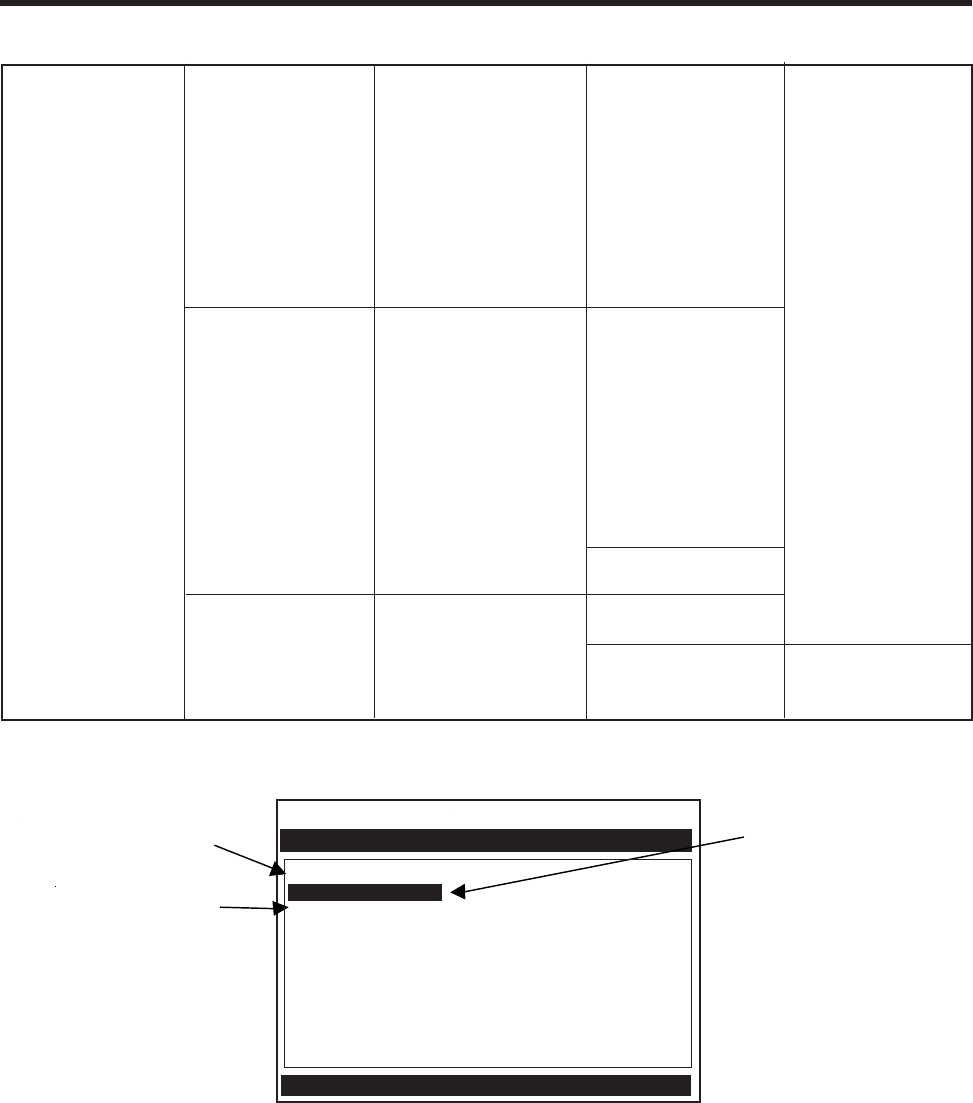
2-43
1010NFM-3J
Section 2
2.7.1 SPAN DATA
The Span Data menu allows you to set 0% and 100% output limits for volumetric flow (Vfo), absolute
flow (Vfab), sonic velocity (Vs) and other outputs (see next page). Each menu cell shows appropriate
rate units and time base. If you change flow rate units after spanning the system, the computer auto-
matically updates the output data setup to reflect the change. Span limits apply to both the analog
outputs and the on-screen stripchart. The flow outputs operate as follows:
Span Data Max Flow (Units) x.xxx (numeric entry)
Min Flow (Units) x.xxx (numeric entry)
Max Vs m/s x.xxx (numeric entry)
Min Vs m/s x.xxx (numeric entry)
Max S.G. x.xxx (numeric entry)
Min S.G. x.xxx (numeric entry)
Max Viscosity cS x.xxx (numeric entry)
Min Viscosity x.xxx (numeric entry)
Max Temperature x.xxx (numeric entry)
Min Temperature x.xxx (numeric entry)
Set Alarm Level High Flow (Units) x.xxx (numeric entry)
Low Flow (Units) x.xxx (numeric entry)
High S.G. x.xxx (numeric entry)
Low S.G. x.xxx (numeric entry)
High Viscosity cS x.xxx (numeric entry)
Low Viscosity cS x.xxx (numeric entry)
High Temperature x.xxx (numeric entry)
Low Temperature x.xxx (numeric entry)
Interface Vs m/s x.xxx (numeric entry)
Aeration % x.xxx (numeric entry)
Makeup Latch Off
On
Calibrate Flowrate Intrinsic
Kc Numeric entry
Multipoint Point # xx (numeric entry)
Indicated Rate x.xxx (numeric entry)
% Correction x.xxx (numeric entry)
Data Span/Set/Cal
THE DATA SPAN/SET/CAL MENU STRUCTURE
Siemens 2 Channel [1] Channel 1
Define data Alarm thresholds
Data Span/Set/Cal
Span Data
Set Alarm Levels
Calibrate Flowrate Intrinsic
Use this menu to define
setpoints for the alarm
relay outputs.
Use this menu to set the
low and high range for
analog outputs.
Use this menu cell to
enter a calibration
slope factor for
volumetric flow (Vfo).

2-44
1010NFM-3JSection 2
Maximum span values represent: Minimum span values represent:
100% of span 0% of span
Current output of 20 mA Current output of 4 mA
Voltage output of 10 Vdc Voltage output of 0 Vdc
Pulse output of 5000 Hz Pulse output of 0 Hz
Max Flow
The [Max Flow] menu cell stores the maximum range for the flow rate output (Vfo). It can be a positive
or negative value. Enter the data using the flow rate units you selected. This entry also spans the
unsigned flow variable (Vfab).
To enter the Max. Flow Range Setting:
To activate numeric entry press
Use the numeric keys to type the maximum flow rate (100% of range).
To store the data press
Min Flow
The [Min Flow] menu cell stores the minimum range for the flow rate output (Vo). It can be a positive or
negative value (to reflect bi-directional flow). However, the minimum span for the unsigned flow (Vfab)
is always zero. Enter the data using the flow rate units you selected.
To set the Min. Flow Range:
To activate numeric entry press
Use the numeric keys to type the minimum flow rate (0% of range).
To store data press
The following Span Data items are set in the same way as the two previously shown examples by
entering numeric values and storing the data.
ENT
ENT
Vfab is the absolute magnitude of the volumetric flow rate (Vfo). There
are no menu cells provided to span this output. Vfab shares the Vfo
span entries. The Vfab minimum span is always zero. The maximum
span for Vfab is the largest absolute value of either the min. or the max.
flow rate (Vfo) entries. For example, a span between +10 GPM and -30
GPM, spans the Vfab output from 0 GPM to 30 GPM.
Vfab
Spanned Absolute
Volumetric Flow Rate:
Vs is the sonic velocity in meters-per-second (m/s) of the flowing liquid.
The min. and max. Vs entries establish the Vs span. Max Vs (m/s)
defines 100% of span. The Min Vs (m/s) defines 0% of span.
Vs
Spanned Liquid
Sonic Velocity:
The minimum and maximum flow rate entries establish the Vfo span.
The [Max Flow] menu cell sets 100% of span. The [Min Flow] menu cell
sets 0% of span. Use signed numbers for bi-directional spanning. Note
that negative (reverse) flow always is lower than positive flow, whatever
its absolute magnitude. For example, for a flow measurement range of -
30 GPM to +10 GPM, the 4 mA span will be -30 GPM, and the 20 mA
span will be +10 GPM.
Vfo
Spanned Volumetric
Flow Rate:

2-45
1010NFM-3J
Section 2
Max Vs m/s
The [Max Vs m/s] menu cell stores the maximum range for the sonic velocity output. The sonic velocity
(Vs) appears on the Stripchart display and can drive any analog output or the alarm relay. The [Max Vs
m/s] menu cell restricts this parameter to a maximum range of 2100 m/sec.
Min Vs m/s
The [Min Vs m/s] menu cell stores the minimum range value for the sonic velocity output. The sonic
velocity (Vs) can be displayed on the Stripchart and drive any analog output or the alarm relay. The
[Min Vs m/s] menu cell restricts this parameter to a minimum range of 400 m/sec.
Max S.G.
The [Max S. G.] menu cell stores the maximum range value for the specific gravity of a liquid. The
specific gravity (S.G.) will be displayed as the maximum on the Stripchart.
Min S.G.
The [Min S.G.] menu cell stores the minimum range value for the specific gravity of a liquid. The
specific gravity will be displayed as the minimum on the Stripchart.
Max Viscosity cS
The [Max Viscosity cS] menu cell stores the maximum range for the analog span. The viscosity units
are centistokes with no alternatives offered.
Min Viscosity cS
The [Min Viscosity cS] menu cell stores the minimum range for the analog span. The viscosity units
are centistokes with no alternatives offered.
Max Temperature
The [Max Temperature] menu cell stores the maximum temperature range for the analog span. If
metric preferences are selected prior to site creation the temperature units will be in Centigrade. If
English preferences are selected prior to site creation the temperature units will be in Fahrenheit.
Min Temperature
The [Min Temperature] menu cell stores the minimum temperature range for the analog span. If metric
preferences are selected prior to site creation the temperature units will be in Centigrade. If English
preferences are selected prior to site creation the temperature units will be in Fahrenheit.
2.7.2 SET ALARM LEVELS
The Alarm Setpoints menu allows you to select system alarm functions. Alarms appear locally on the
LCD digital display. In addition, you can use the Relay Setup menu to assign those functions to the
system’s relays. You may select from high or low energy or flow rate, liquid interface (Vs) and liquid
aeration alarm functions. Entry of all alarm setpoints is accomplished using the selected rate units.
You can enable or disable a Makeup Alarm Latch to keep the makeup alarm active until you reset it
manually by an <Fn>6 simultaneous key press.
To access the Alarm Setpoints menu press .

2-46
1010NFM-3JSection 2
High Flow
The [High Flow Alarm] menu cell allows you to set the HI Alarm relay trip-point and the position of the HI
Alarm cursor on the Stripchart Display. The entered value must fall within the volumetric flow (Vfo)
analog span for the HI Alarm cursor to appear on the Graphic Screen.
To set the High Flow Alarm:
To activate numeric entry press
Use numeric keys to type the High Flow Alarm setpoint in the selected flow rate units.
To store data press
Low Flow
The[ Low Flow] menu cell allows you to set the LO Alarm relay trip-point and position of the LO Alarm
cursor on the Stripchart Display. The entered value must fall within the volumetric flow (Vfo) analog
span for the Low Alarm cursor to appear on the Graphic Screen.
To set the Low Flow Alarm:
To activate numeric entry press
Use the numeric keys to type the Low Flow alarm setpoint.
To store data press
The following Alarm Relay Setpoints are set in the same way as the two previously shown examples by
entering numeric values and storing the data.
High S.G.
This selection sets the High S.G. alarm function the specific gravity of a selected liquid.
Low S.G.
This selection sets the Low S.G. alarm function the specific gravity of a selected liquid.
High Viscosity cS
The [High Viscosity cS] menu cell sets the high liquid viscosity alarm relay setpoint. The viscosity units
are centistokes with no alternatives offered.
Low Viscosity cS
The [Low Viscosity cS] menu cell sets the low liquid viscosity alarm relay setpoint. The viscosity units
are centistokes with no alternatives offered.
High Temperature
The [High Temperature] menu cell sets the high temperature alarm relay setpoint. If metric preferences
are selected prior to site creation the temperature units will be in Centigrade. If English preferences are
selected prior to site creation the temperature units will be in Fahrenheit.
Low Temperature
The [Low Temperature] menu cell sets the low temperature alarm relay setpoint If metric preferences
are selected prior to site creation the temperature units will be in Centigrade. If English preferences are
selected prior to site creation the temperature units will be in Fahrenheit.
ENT
ENT

2-47
1010NFM-3J
Section 2
Interface Vs (m/s) meters-per-second
The [Interface Vs m/s] menu cell sets the Interface Vs setpoint. The relay changes state when the
variable exceeds the user setpoint
Aeration %
The System 1010 surpasses all other transit-time systems in its ability to operate with substantial
aeration (caused by entrained gases, mixing condition or cavitation). Some applications may require
an alarm indication if aeration exceeds a particular level. The meter detects this aeration level and
provides this data as an output. The aeration percentage triggers the alarm relay whenever it meets or
exceeds the threshold you set in this menu cell. The aeration percentage (Vaer %) appears in the
Liquid Data section of the Diagnostic Menu. The digital display screen also shows the current aeration
percentage.
NOTE: Severely aerated conditions may induce meter fault. The 50% default usually allows
enough leeway for continued operation. For intermittent faults, see memory interval
in the Output Control menu.
To set the Aeration % Alarm:
To move the cursor to activate numeric entry press
Use the numeric keys to type the Aeration percentage setpoint.
To store data press ENT
Makeup Latch
A fault condition (caused by an empty pipe or a transient loss of power, etc.) could temporarily interrupt
operation. After recovery from the fault, the meter executes an in-process makeup to restore operating
parameters. During the makeup, the meter sets a Makeup Alarm flag, which clears upon completion.
Therefore, unless you were monitoring the unit continuously, you could miss the fact that an In-process
Makeup occurred. The Makeup Alarm Latch alerts you that the system implemented a Makeup by
holding the Makeup Alarm active until you reset it manually by the simultaneous keystrokes: <Fn>6
(where “n” represents the measurement channel). In addition, if the Datalogger is active with Status
Alarms selected, generating a Datalogger report will reset the Makeup Alarm Latch. This ensures that
the Alarm does not appear on succeeding Datalogger reports. A Makeup Alarm appearing on a subse-
quent report indicates that an In-Process Makeup must have occurred since the last Datalogger report.
To Enable (or Disable) the Makeup Latch:
To access the [Makeup Latch] option list press
Move the cursor to select either [On or Off] by pressing
To turn Makeup Latch [On] or [Off] press ENT

2-48
1010NFM-3JSection 2
2.7.3 CALIBRATE FLOW RATE
The 1010’s intrinsic calibration is excellent as confirmed by numerous laboratory and field trials under
diverse application conditions. We thus can confidently say that in any given application, the majority of
conventional flowmeters can not match the system’s measurement range or its linearity. Some appli-
cations may require an output adjustment to match an official external reference. The Calibrate Flow
Rate menu allows you to select a calibration mode. The right-hand column shows the active calibration
mode. You can select Intrinsic (factory), Kc (Slope Correction) or Multipoint (Non-linear) Calibration.
Selecting either of the external calibration modes will not eliminate the Intrinsic (factory) calibration. You
can use this menu cell to switch between Intrinsic, Kc or Multipoint at any time.
Kc Calibration
For most applications, the measured flow range produces a linear meter response. Therefore, the Kc
(slope correction) calibration is the preferred method since it only requires a single correction factor for
all the flow rates encountered. Changing the calibration can cause profound changes in a flowmeter’s
operating characteristics. Use only the most respected flow standard to obtain a correction factor. The
percentage you enter must provide an accurate and consistent shift across the entire flow range
anticipated for the application.
To obtain the Kc factor, compare flow total data taken simultaneously from the 1010 and a reference
meter whose accuracy meets the required standard. Allow both meters to accumulate flow total data
long enough to average out any differences due to flow fluctuation between the two meter locations.
Compare outputs of the two totalizers to determine percentage increase (+) or decrease (-) that is
necessary to produce the best average correlation between System 1010 and the reference standard.
For example, entering [-0.29] will produce a reduction of 0.29% in the calibration at all flow rates.
NOTE: Always enter the + or - sign first.
To calculate Kc:
To enter the Kc Factor:
To enable numeric entry press .
Use the numeric keys to enter the required Kc (as calculated above). Note that the Kc value
can be negative or positive. Enter the - or + sign first, then type in the calibrated value.
To store the data press .
Note that Kc now appears in the right-hand column of the [Calibrate Flow Rate] menu cell with
its new value. Also note that this Kc value can be viewed on the site printout.
MultiPoint Calibration
MultiPoint calibration serves applications that require a non-linear meter calibration. You can enter
correction factors for up to ten significant points over the entire measurement range. This is accom-
plished by:
(a) Selecting up to 10 separate calibration points by entering a raw (un-calibrated) flow rate.
(b) Entering a negative or positive correction for each calibration point that you select.
ENT
Kc = x 100
Actual Rate
Indicated Rate -1
Kc = x 100
2-49
1010NFM-3J
Section 2
Press to move to the [Indicated Rate] field, then to enable numeric entry.
Use the numeric keys to type a flow rate for point #1, then . The highlight moves
to the [% Correction] field for point #1. Press to enable numeric entry.
Use the numeric keys to type the required % correction for point #1.
Press . The highlight returns to the [Point #] field.
To enable numeric entry press then type [2] (for the second calibration point).
The cursor moves to the point #2 - [Indicated Rate] field.
Use the numeric keys to type a flow rate for point #2. The value entered here must be of a
greater magnitude than the value entered for point #1.
Press . The cursor moves to the [% Correction] field.
Like the Kc slope correction described in the previous section, you locate critical flow rate points by
comparing flow total data taken simultaneously from the 1010N and a reference meter whose accu-
racy meets the required standard. Again, it is important to note that you must allow both meters to
accumulate flow total data for long enough to average out any differences due to flow fluctuation be-
tween the meter locations.
Compare the two flow total readings to identify up to ten separate points (termed raw flow rates) where
there are significant deviations between System 1010N and the reference meter. Calculate correction
factors (either negative or positive percentages) for up to ten points along the flow range. For example,
entering [-0.1] for point 1 produces a negative 0.1% change in the meter output whenever the system
measures the raw flow rate specified for point 1, etc. The valid range for each percent correction is
from -50% to +50%. If you enter a value outside of this range, the flow computer will set the calibration
factor to the nearest limit.
Use these to match System 1010N’s output with the reference meter’s response curve. Selected
calibration points must increase in magnitude from point 1 to point 10 (or the last point that you wish to
calibrate).
NOTE: You must enter the raw flow rates in ascending order.
To perform a MultiPoint Calibration:
To access the [Calibrate Flow Rate] option list press
Move the cursor up to [MultiPoint], then press
This selects the MultiPoint calibration screen, which shows:
ENT
ENT
ENT
ENT
Point # (point 1 selected)
Indicated Rate (shows current rate for point # 1)
% Correction (amount of correction applied either (-) or (+) percentage)
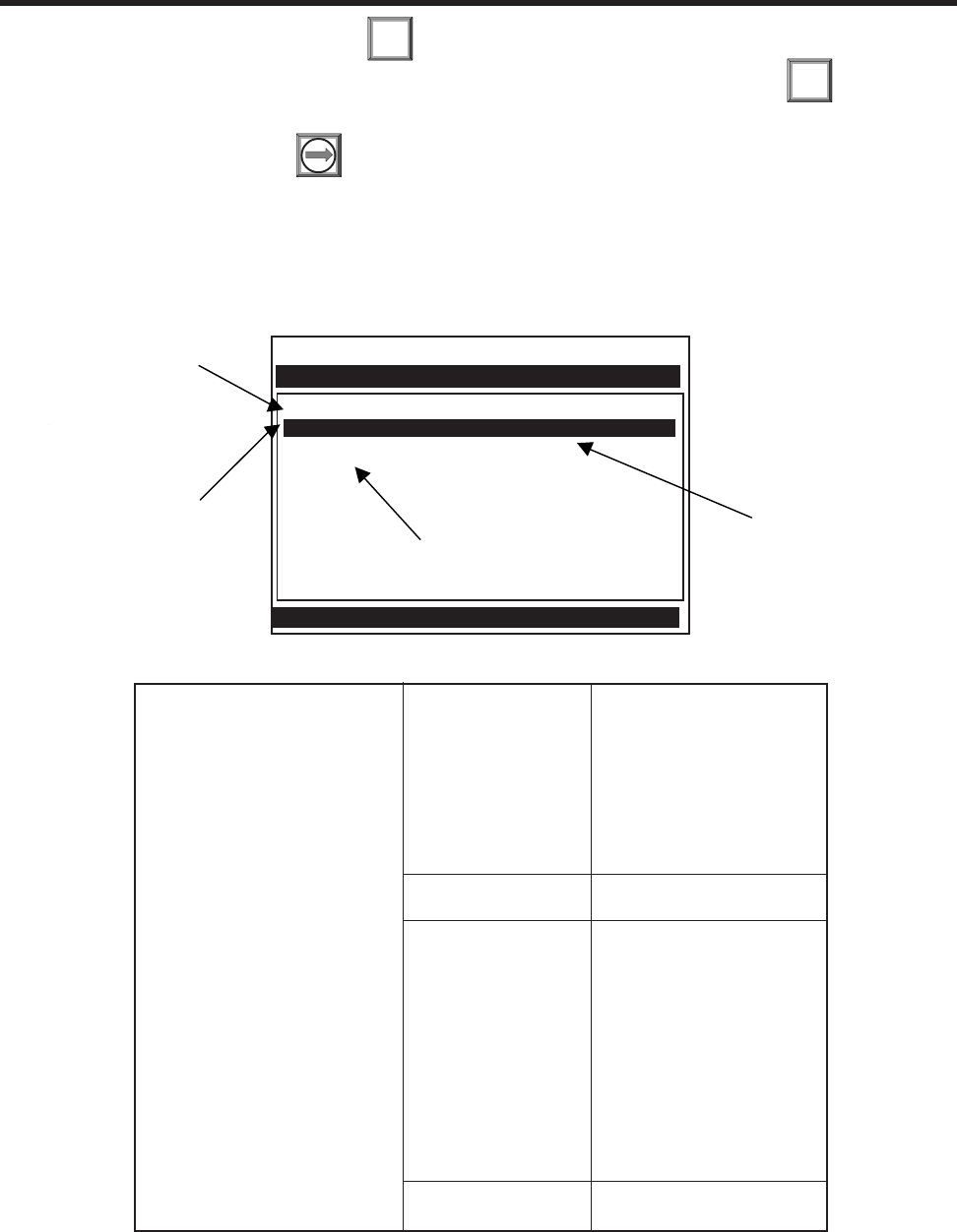
2-50
1010NFM-3JSection 2
To enable numeric entry press
Use the numeric keys to type the required % correction for point #2. Press .
Repeat this procedure for all required calibration points. After entering the last Flow
Calibration Point press to exit MultiPoint calibration.
ENT
ENT
2.8 THE STRIPCHART SETUP MENU
This menu becomes available after picking a Meter Type and Measurement Channel. Use Stripchart
Setup to select a data category, the type of scaling and the update interval for the on-screen stripchart
display. You can also clear the stripchart screen.
Siemens Dual Path SITE1
Select Data Units or Percent Display
Stripchart Setup
Select Data LiquIdent
Data Display Data Rate Units
Time Base 1 second
Stripchart Clear Yes
Use this menu cell
to select an update
interval for the
stripchart.
Use this menu cell
to clear the current
stripchart.
Use this menu cell
to select a data
item to display on
the stripchart.
Use this menu cell
to select whether
the stripchart
shows data as
either a rate or a
percentage of
span.
Stripchart Setup Select Data Vfo
Vfab
Visc
Temp
Vs
Valc
Vaer
Vsg
Data Display Data Rate Units
Percent of Span
Time Base 1 Second
3 seconds
6 seconds
12 seconds
24 seconds
1 minute
3 minutes
6 minutes
12 minutes
24 minutes
1.2 hours
Stripchart Clear Yes
No
THE STRIPCHART SETUP MENU STRUCTURE
2.8.1 SELECT DATA
The [Select Data] option list allows you to select a data function for the on-screen stripchart display.
The stripchart provides a data plot using the selected data units and time base. All data items except

2-51
1010NFM-3J
Section 2
2.8.3 TIME BASE
The [Time Base] option list defines the stripchart x-axis display interval. The stripchart plots an average
of readings obtained during the elapsed time between reports. Stripchart resolution is 1 data point per
pixel, of which there are approximately 100 on the short strip-chart plot and approximately 200 on the
full screen stripchart plot. Five pixel reports occur between major stripchart divisions.
NOTE: The stripchart display identifies the “real time” when the computer records the most
recent graduation. You can time-stamp any graduation by counting back in graduation
intervals. The default interval setting is 1 second.
To select a Time Base:
To access the [Time Interval] option list press
Move the cursor to the desired interval by pressing
To store your selection press
Valc and Vaer use the span settings from the [Data Span/Set/Cal] menu. The following data Items are
available for the Stripchart Display:
•Vfo ........................... (spanned flow) *default
•Vfab ......................... (spanned unsigned flow magnitude)
•Visc ......................... (viscosity)
•Temp ....................... (temperature)
•Vs ............................ (sonic velocity)
•Valc.......................... (signal amplitude)
•Vaer ......................... (aeration/cavitation)
•Vsg .......................... (spanned unsigned flow magnitude)
To select a data item for the stripchart:
To access the [Select Data] option list press
Move the cursor to the desired item by pressing
To store your selection press
2.8.2 DATA DISPLAY
The [Data Display] option list allows you to select a format for the stripchart plot. It offers the choice of
displaying data either in the current data rate units or as a percent of span defined in the Data Span/
Set/Cal menu. [Data Rate Units] is the default selection.
To select a format for the data display:
To access the [Data Display] option list press
To move the cursor to the required scale unit press
To store your selection press
ENT
ENT
ENT
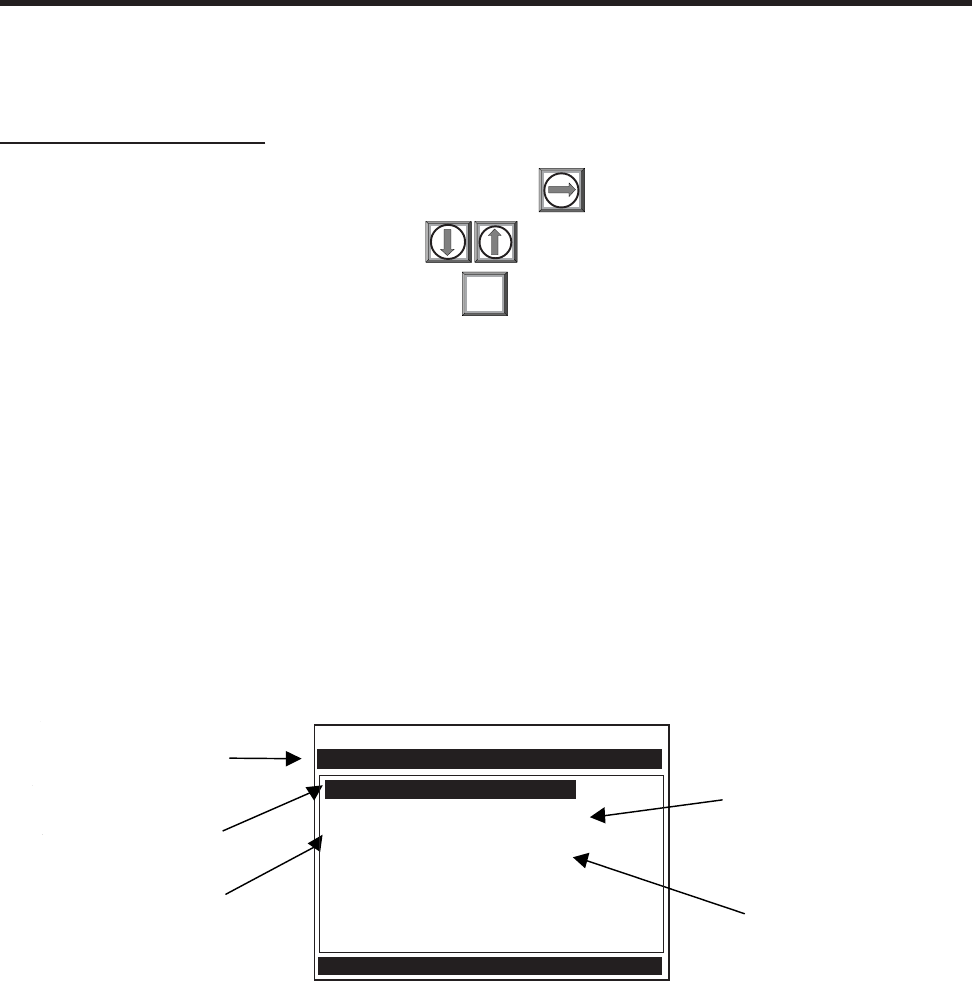
2-52
1010NFM-3JSection 2
2.8.4 STRIPCHART CLEAR
Use this menu cell to clear the stripchart. Selecting [Yes] erases all current stripchart data.
To erase the Stripchart plot:
To access the [Stripchart Clear] option list press
Move the cursor to [Yes] by pressing
To clear the current Stripchart plot press
2.9 THE DATALOGGER SETUP MENU
This menu becomes available after picking Meter Type and Measurement Channel.
The integral Datalogger records data for eventual display on Graphics Screen, or for connection to an
RS-232 compatible external device (printer, computer, network, etc.). Use Datalogger Setup to select
data items and real-time events for datalogger reports. You can also set the logging interval, operating
mode and screen format. The Datalogger Setup menu allows you to choose time interval-based data
categories or event-based status alarms, and to specify the interval between data reports.
View Datalogger reports on the display screen or transmit them via the RS-232 Serial Port to external
printers and computers. Note that a single-channel meter uses a compression algorithm to maximize
data storage. This disables back scrolling of datalogger reports.
ENT
Datalogger Mode Off
Datalogger Data None
Log Time Interval 1 Min.
Data Logger Events None
Display Datalogger Off
Siemens Dual Path Path 1
Select datalogger destination
Datalogger Setup
Use this menu cell
to select a logging
interval.
Use this menu cell to
pick a destination for
Datalogger reports.
Use this menu cell to
select real-time
Datalogger triggers.
Use this menu cell to
select items fo
r
Datalogger reports.
Use this menu cell to
send Datalogger
reports to selected
destination and pick
up a line wrap mode.

2-53
1010NFM-3J
Section 2
Datalogger Setup Datalogger Mode Off
Memory
RS-232 Output
Datalogger Data None
Site Id
Date
Time
Flow
Average Flow
Raw Flow
Total
Vs
Valc
Aeration
S.G.
Alarms
Temperature
Delta T (usecs)
Analog Inputs
Log Time Interval 5 Sec.
10 Sec.
15 Sec.
30 Sec.
1 Min.
5 Min.
15 Min.
30 Min.
1 Hr.
2 Hr.
4 Hr.
6 Hr.
12 Hr.
24 Hr.
Demand
Datalogger Events None
Relay 2
Relay 1
Fault Alarm
Memory
Makeup
Spacing
Empty
Aeration
Interface
Flow Alarm
Display Datalogger Off
No Line Wrap
Line Wrap
THE DATALOGGER SETUP MENU STRUCTURE
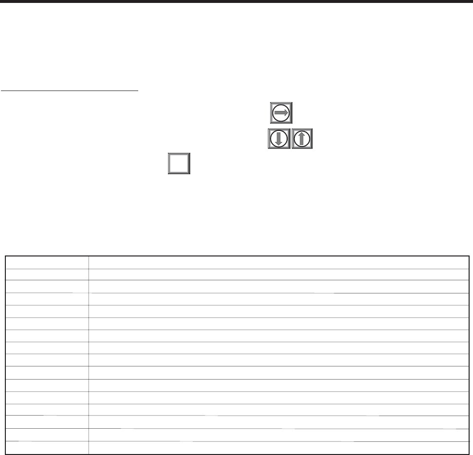
2-54
1010NFM-3JSection 2
2.9.1 DATALOGGER MODE
The [Datalogger Mode] option list allows you to disable Datalogger, transmit reports to an external
target via RS-232 port, or store selected data for later display. The default setting is [Off]. After enabling
the Datalogger, select a data format before generating a report.
To select a Datalogger Mode:
To access the [Datalogger Mode] option list press
Move the cursor to the desired mode by pressing
To store the selection press
2.9.2 DATALOGGER DATA
Set the Datalogger to record any or all of the data offered on the [Datalogger Data] option list shown
below. However, recording unneeded data wastes valuable system RAM. We recommend that you
always select [Site ID] (name) and [Time] to identify each line of data.
ENT
If you select Alarms, the Datalogger logs the state of each alarm function upon generating
a report. A dash [-] represents an inactive alarm.
A letter code represents an active alarm (see next page).
*The Time field expands to HH.MM.SS when you select a logging interval of more than once per minute.
None Default – Datalogging is disabled.
Site ID You entered this site name when you created the site.
Date The report date according to the meter’s real time clock. (Format: MM.DD.YYYY)
Time The report time according to the meter’s real time clock. (Format: HH.MM)*
Flow The instantaneous flow measured at the time of the report.
Average Flow The average flow rate measured since the last report.
Raw Flow The uncompensated flow rate in in/sec2 (only zeroed - no Reynolds number curve applied).
Total The total flow accumulation measured at the time of the report.
Vs The average liquid sonic velocity since the last report.
Valc The signal strength measured at the time of the report.
Aeration The aeration percentage recorded at the time of the report.
S.G. Specific Gravity at current operating temperature.
Alarms The letter codes of any alarms active at the time of the report (see below).
Delta T (uSecs) The Up to Down transit-time difference measured at the time of the report.
Temperature The instantaneous supply aand return temperatures at the time for the report.
Analog Inputs Any data appearing on an auxiliary input at the time of the report.
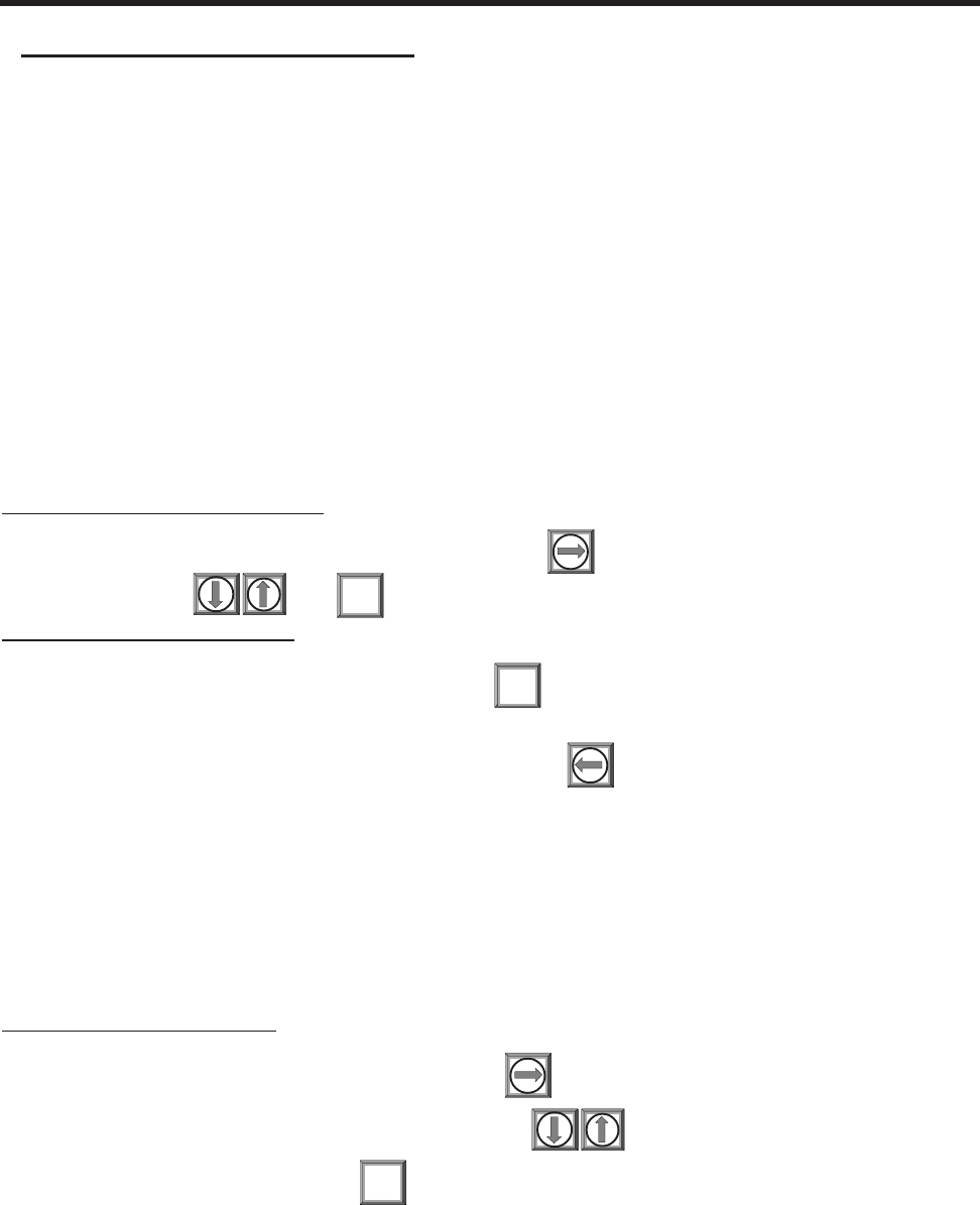
2-55
1010NFM-3J
Section 2
Alarm Letter Codes and Descriptions
S ...... Spacing............... Transducer spacing may need re-adjustment
E ...... Empty ................. Pipe is empty
R ...... Rate .................... Flow above High setting or below Low setting
F....... Fault.................... Three continuous seconds without new data update
A....... Aeration .............. Current aeration percentage exceeds the alarm setpoint
M ...... Memory ............... Last valid reading for a selected interval during Fault condition
K ...... Makeup ............... In-Process Makeup occurred
I ........ Interface .............. Liquid Vs exceeds interface alarm setpoint
P ...... Pig ...................... Pig passage detected (optional)
Z....... ZeroMatic ............ ZeroMatic signal fault
NOTE: The time interval-based Datalogger records the state of all the alarms at the selected
report time only. Therefore, if an alarm condition resets before the report time, it
would not appear on the report. Use Datalogger Events to log transient alarms. This
mode generates a report upon the detection of an alarm event.
To select Datalogger Data items:
To access the [Datalogger Data] option list press . Move the cursor to a desired data item
by pressing then to select it. Note that a plus sign (+) appears before the item.
To de-select Datalogger Data:
Move the cursor to the data item then press . Note that this removes the plus sign (+) from
the item.
After selecting/deselecting all desired items press to leave the [Datalogger Data] option
list.
2.9.3 LOG TIME INTERVAL
The Datalogger records a “snapshot” of conditions at each log time interval. Datalogging uses a con-
siderable amount of RAM, so only select short log intervals if it is fully justified.
NOTE: The meter maps the first Datalogger report time to an even division of its clock. Sub-
sequent reports will conform to the selected interval.
To set the Log Time Interval:
To access the [Log Interval] option list press
Move the cursor to desired interval by pressing
To store your selection press
ENT
CLR
ENT
2.9.4 DATALOGGER EVENTS
System 1010 offers “event-based” data logging that operates concurrently with “time interval” based
data logging. The event-based function generates a Datalogger report upon the triggering of any of the
alarms. This is useful for recording transient alarms (e.g., a liquid interface, or a short aeration alert.)
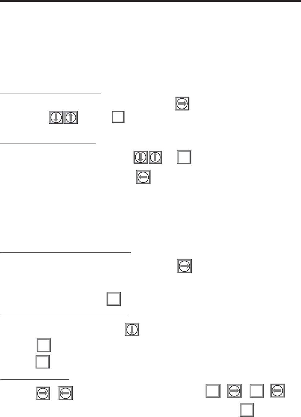
2-56
1010NFM-3JSection 2
NOTE: An Alarm Event report will be generated immediately after the transition from a non-
alarm to an alarm event. The reverse situation (alarm state to non-alarm state) does
not trigger the event-based Datalogger.
Event-based Datalogger messages conserve memory. However, if you use this feature to monitor a
level such as Flow Alarm, set the alarm threshold high enough to avoid repetitive triggering. You must
select Site ID (Name) and Time to “time-stamp” the alarm events. Note that on the Datalogger report,
a [-] represents a reserved letter code space (inactive alarm) and a letter code represents an active
alarm.
To select Datalogger Event items:
To access the [Datalogger Events] option list press . Move cursor to desired item by
pressing then press to select it. Note that a plus sign(+) appears before the
item.
To de-select Datalogger Events:
To move the cursor to the item press then . Note that this removes the plus
sign (+) from the item.
After selecting all desired items press to leave the [Datalogger Events] option list.
2.9.5 DISPLAY DATALOGGER
Use this menu cell to enable and format the on-screen datalogger. You can allow the report to scroll on
the screen with or without line wrapping. Selecting line wrap, forces a line feed after approximately 40
characters. This command is effective only after you select data items and the Datalogger has accu-
mulated some data.
CLR
To enable the on-screen datalogger display:
To access the [Display Datalogger] option list press
Move the cursor to the desired function.
To invoke the function press
To scroll the on-screen datalogger display:
To display one line at a time press
Use key to scroll down one screen (10 lines) at a time.
Use key to jump to 15 lines of the last screen.
In No Line Wrap mode:
Use or to scroll one column to the left or right. Use + or +
To scroll 8 columns to the right or the left. To get out of the display, press
ENT
ALT
=
ALT
+
MENU
ENT
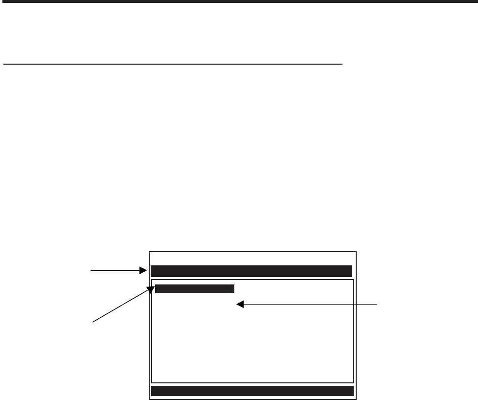
2-57
1010NFM-3J
Section 2
NOTE: In single channel 1010’s the datalogger uses a compression scheme that precludes
backward scrolling.
Important point about Datalogger resources and dual-channel systems.
When logging data on both measurement channels simultaneously, the Datalogger stores reports in
a single common file. It is important that you select Site ID to appear on each line of data so that you
can always identify which channel generated report.
2.10 THE I/O DATA CONTROL MENU
This menu becomes available after picking a Meter Type and Channel.
Use this menu to assign functions for the meter’s analog outputs and optional inputs. The Analog Out
Setup assigns functions to the meter’s current, voltage and pulse rate outputs. Each menu cell pre-
sents an option list of the available data items. In addition, you can set up the alarm relays, enable and
span the analog input ports.
Siemens Dual Path SITE1
Assign Data to Analog Outputs
I/O Data Control
Analog Out Setup
Relay Setup
Analog Input Setup
Use this menu to enable
and span optional
analog inputs.
Use this menu to
assign data functions
to analog outputs.
Use this menu t
o
assign alarm
functions to rela
y
outputs.

2-58
1010NFM-3JSection 2
2.10.1 ANALOG OUTPUT SETUP
System 1010 provides current, voltage and pulse-rate analog outputs. Analog Output Setup allows you
to assign data functions for these signals. The flow computer’s terminal strip contains the analog
output terminals.
I/O Data Control Analog Output Setup Io1/Io2 Vfo
Vfab
Vs
Valc
Vaer
Vsg
Viscosity
T1
Iin1
Iin2
Iin3*
Iin4*
Vo1/Vo2 See Io option list
Pgen1 See Io option list
Relay Setup Relay 1 Off
Power On
S.G.
Hi Temperature
low Temperature
High Flow
Low Flow
Flow Alarm
Fault Alarm
Spacing
Empty
Aeration
Interface
Reverse Flow
BatchTot
Pos Total
Neg Total
Soft Fault (Multi-beam)
Relay 2 See Relay 1 list for 2, 3 & 4
Analog Input Setup Iin1 Input Off
Aux (X or F-Option)
S.G. (F-Option)
cS (F-Option)
cP
PSIA (BAR) - (F-Option)
BARA
Deg F
Deg C
4 mA numeric entry
20 mA numeric entry
Iin2 Input See Iin1 option list
4 mA numeric entry
20 mA numeric entry
THE I/O DATA CONTROL MENU STRUCTURE
*For Multi-Path and Arithmetic operating modes only.
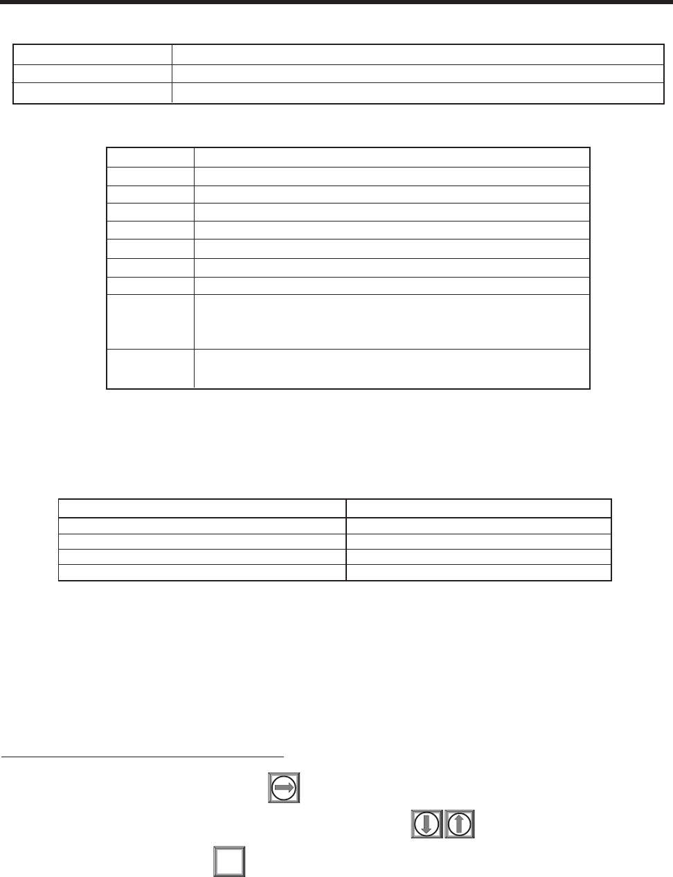
2-59
1010NFM-3J
Section 2
Assigning Io Output Functions
The Io analog output is a self-powered, isolated 4-20mA DC signal that varies linearly in relation to a
selected data function.
CAUTION: Do not connect to a powered loop.
To assign a function for the current output:
From [Analog Out Setup], press twice to access the [Io] option list.
To move the cursor to the desired data function press
To store selection press ENT
NOTE: For Multi-Channel meters, refer to drawing 1010MN-7 for details. For Expanded I/O
modules, refer to drawing 1010N-7-7 and Addendum 1010FMA-14 for details.
Model Number and I/O Module Installation Drawing and Page Number*
1010N 1010N-2-7 (Sheet 2 of 2)
1010N with 1010N-7 Expanded I/O Module 1010N-7-7 (Sheet 2 of 3)
1010DN 1010N-2-7 (Sheet 2 of 2)
1010DN with 1010N-7 Expanded I/O Module 1010N-7-7 (Sheet 2 of 3)
Table To Determine Proper I/O Installation Drawings
*Note: For Ultra Precsion transducers see 1010N-7-7 (sheet 3 of 3).
Io (Isolated current) 4 to 20 mA varies in proportion to an assigned data function.
Vo (DC voltage) 0 to 10 Vdc varies in proportion to an assigned data function.
Pgen (TTL logic) 0 to 5000 Hz varies in proportion to an assigned data function.
System 1010 Analog Outputs
Vfo Spanned volumetric/mass flow rate
Vfab Spanned unsigned flow magnitude
Vs Spanned liquid sonic velocity
Valc Receive signal amplitude
Vaer Relative degree of liquid aeration/cavitation
Vsg Spaned specific gravity
Viscosity System liquid viscosity
T1 Current liquid temperature
Iin1, Iin2 Represents a re-transmit of the analog input signals (e.g.,
Pressure and Temp inputs can be transmitted on the 4/20
mA output.)
Iin3, Iin4 Same as Iin1 and Iin2 above but only available for opera-
tion in Multi-Beam and Arithmetic modes.
Analog Out Setup Data Categories
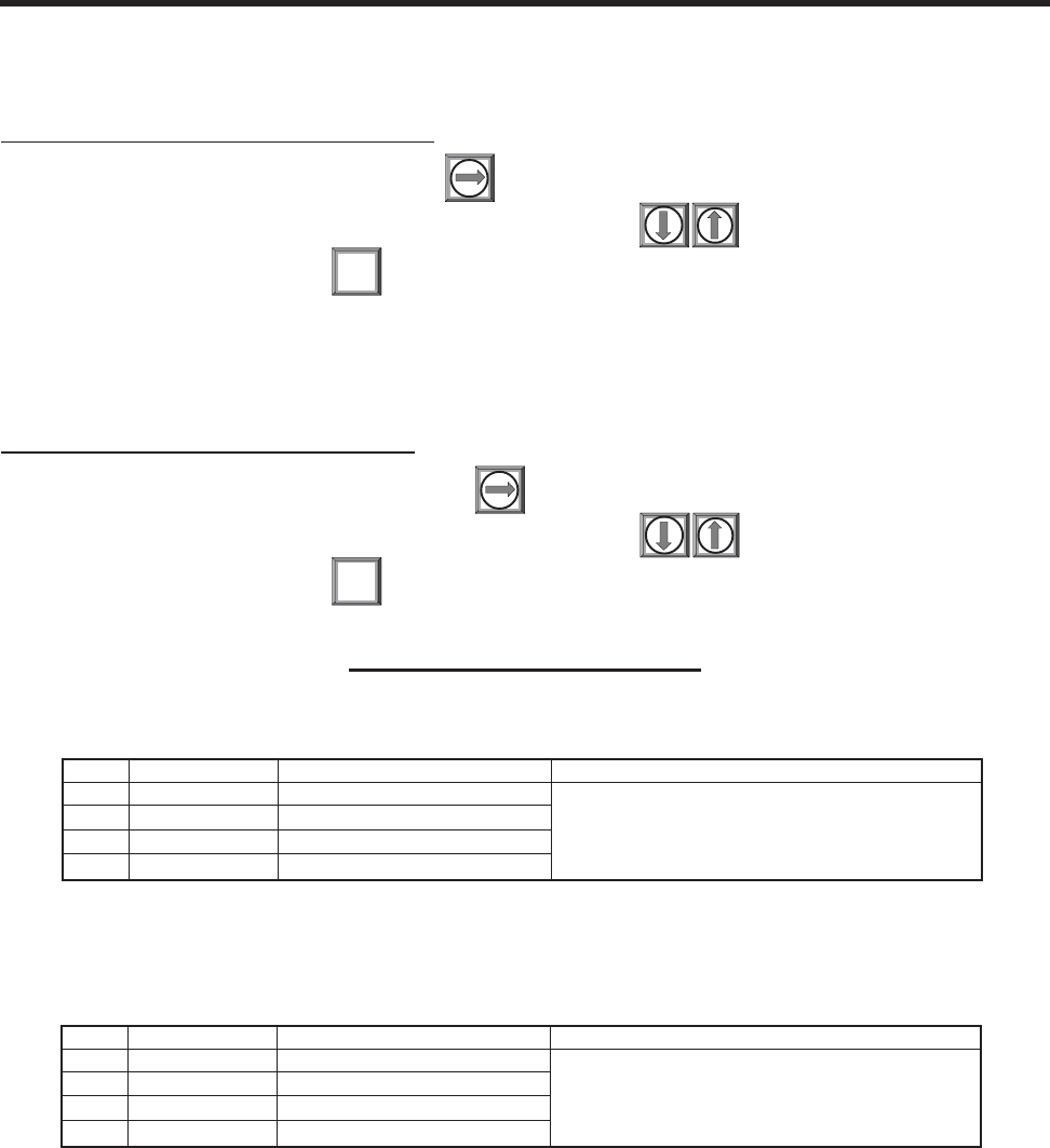
2-60
1010NFM-3JSection 2
2.10.2 RELAY SETUP
Use this menu to assign a function to channel relays. System 1010 supports 2 types of relay outputs,
Alarm Relay and Pulse Relay. Alarm Relay outputs operate in “fail-safe” mode. The relay(s) are ener-
gized under normal conditions - an alarm condition causes the relay(s) to de-energize until alarm
clears. The Pulse Relay output supports totalizer and batch relay functions. Output is a pulse width
approximately 200 ms; maximum activation rate is 2.5 pulses per sec. If totalizer pulses exceed this
rate, excess pulses are stored in an overflow register. This allows the relay to “catch up” when flow
decreases enough.
Assigning Vo Output Functions
The Vo analog output is a 0-10 VDC signal that varies linearly in relation to a selected function.
To assign a function to the voltage output:
To access the [Vo] option list press
To move the cursor to the desired data function press
To store selection press
Assigning Pgen Output Functions
The Pgen analog output is a buffered TTL-compliant pulse rate signal, similar to the pulse outputs of
flowmeters such as turbines. It varies linearly from 0-5000 Hz in relation to a selected data function.
To assign a function to the Pgen output:
To access the [Pgen] option list press
To move the cursor to the desired data function press
To store selection press
ENT
ENT
PULSE OUTPUT (Pgen Wiring)
1010N & 1010DN with 1010N-2 Modules
Installation Drawing 1010N-2-7 (Sheet 2 of 2)
PIN# SIGNAL FUNCTION NOTES
11 PGEN 1+ FREQUENCY OUTPUT 1 0 - 5000 Hz, 5 Volt Logic, Square Waveform
12 PGEN 1- REF. GROUND
13 PGEN 2+ FREQUENCY OUTPUT 2
14 PGEN 2- REF. GROUND
1010N & 1010DN with Expanded 1010N-7 I/O Modules
Installation Drawing 1010N-7-7 (Sheet 2 of 3)
(Standard, High Performance and Enhanced Performance Flowmeters)
PIN# SIGNAL FUNCTION NOTES
9 PG1 FREQUENCY OUTPUT 1 0 - 5000 Hz, 5 Volt Logic, Square Waveform
10 PG2 REF. GROUND
11 PG3 FREQUENCY OUTPUT 2
12 PG4 REF. GROUND
TB2
TB2

2-61
1010NFM-3J
Section 2
To assign functions to Relay 1:
To access the [Relay] option list press
To move the cursor to the desired Relay assignment press
To store selection press . Repeat procedure for Relay 2.
ENT
2.10.3 ANALOG INPUT SETUP (optional function)
The Analog Input Setup function assigns an active analog input to a measurement channel/path. The
meter provides four DC current input ports for single and Dual Channel units. The DC current input
ranges from a zero level of 4 mA to a full scale of 20 mA. The [Analog Input Setup] menu cell allows you
to enable this port and then span it to any desired scaling.
For example, when using the analog input viscosity function the numeric variables might be spanned
as follows: 4mA=1 (water) and 20mA=100 (more viscous liquid). This spanning configuration allows
the meter to use this constant numerical change to improve calibration in real time. The various flow-
meter models allow you to associate the analog input to active system variables such as specific
gravity, viscosity and others (see table on next page).
NOTE: Using the <F1> key (Totalizer clear command) also clears all channel totalizers plus
the overflow register described in the last paragraph.
Assigning Relay 1 and 2 Functions
System 1010N, depending on the model, provides at least two alarm relays. Please refer to the Hard-
ware Installation Drawing for wiring details. Relays respond to any of the alarm conditions/data func-
tions included on the Relay Option List.
Not Used Not Active
Power Off Power Off alarm occurs when power fails
S.G. Specific Gravity value relay trip-point
Hi Temperature High temperature value relay trip-point
Low Temperature Low temperature value relay trip-point
High Flow Flow rate exceeds high flow setpoint
Low Flow Flow rate falls below low flow setpoint
Flow Alarm Flow rate exceeds or falls below flow setpoints
Fault Alarm System loses receive signal
Spacing Transducer spacing needs adjusting
Empty Empty pipe alarm
Aeration Aeration percentage exceeds alarm setpoint
Reverse Flow Flow is in negative direction
BatchTot Batch/Sample total advances
Interface Liquid interface setpoint exceeded
Pos Total Positive total volume advances by 1 digit
Neg Total Negative total volume advances by 1 digit
Soft Fault Fault condition - memory mode active
RELAY OPTION LIST

2-62
1010NFM-3JSection 2
Setting up the Analog Current Input
The first step is to enable the DC current input port.
From Analog Input setup:
To access the [Iin] option list press the <Right Arrow> twice.
To move the cursor down to [Aux (n)] press the <Down Arrow> and then <ENT>. This enables
the port to receive an input current. The cursor moves to [4 mA].
To enable numeric entry press the <Right Arrow>. Type a numeric value corresponding to a 4
mA input signal. To store the data press <ENT>. This moves the cursor to [20 mA].
To enable the numeric entry press the <Right Arrow>. Type the numeric value corresponding to
a 20 mA input signal. To store the data, press <ENT>.
2.11 THE DIAGNOSTICS DATA MENU
Some Diagnostic Data items require a successful transducer installation and meter initialization to
become available. These will report [Chan Not Setup] until you complete the installation procedure.
The Diagnostics Data menu provides real-time application and setup data, plus test routines for the
selected channel. To receive the best technical support, please be prepared to report any diagnostic
data item upon request. Note also that these menus contain information that may only be meaningful to
our technical support staff.
The available diagnostic data depends on the meter type and channel configuration. All diagnostics are
available when you select channel 1 or 2 in [Dual Channel Flow], [Ch 1+2 Flow] or [Ch 1-2 Flow]
modes. In [Dual Beam Flow] mode, all diagnostic items are available for [Path 1] or [Path 2]. Some
items are not available (N/A) when you select virtual channel [1 and 2]. In addition, selecting virtual
Channel 3, in either the [1+2 Flow] or [1-2 Flow] modes will limit the list to flow data only.
Note that the flowmeter recognizes the first analog input variable that is assigned to any given param-
eter and ignores any subsequent input with the same assignment. For example, if Iin1 and Iin2 are both
assigned to represent Temperature (Deg F), the meter will only use the temperature input from Iin1.
I/O Data Control Analog Inp Setup Iin1 Input Off
Aux
S.G.
cS
cP
PSIA
BARA
Deg F
Deg C
4 mA numeric entry
20 mA numeric entry
Iin2/Iin3/Iin4 See Iin1 option list
NOTE: Refer to the Installation Drawings or I/O Module markings for the locations of these
inputs and wiring procedures.

2-63
1010NFM-3J
Section 2
Diagnostic Data Flow Data Flow
Flow Vel F/S
Total
Vs m/s
Signal mV
Valc %
Vaer %
Alarm Status
Ancal
HiFlow
LoFlow
Application Info TN uSec
TL uSec
DeltaT nSec
Burst/Sec
% Accepted
Last Makeup
Makeup Status
Liquid Data Temp 1
Temp 2
Reynolds #
Specific Gravity
Viscosity cP
Pressure
Viscosity cS
Site Setup Data fx (drive)
N (burst length)
Ltn in
Vfmax
Vs max m/s
Vs min m/s
Empty %
Samples/Cycles
Max Damping
Min Damping
HF
Test Facilities Makeup
Graph
Tx Up
Tx Dn
Fixed ALC
Tx Up Fixed ALC
Tx Dn Fixed ALC
Graph AutoZero
Print Site Setup No/Yes
Date Site Created xx.xx.xx. xx.xx.xx
DIAGNOSTIC DATA MENU STRUCTURE

2-64
1010NFM-3JSection 2
2.11.1 MAIN DIAGNOSTICS SCREEN
This is the Main Diagnostics Data screen. It provides menus that show Flow, Application, Liquid and
Site Setup information. The Test Facilities menu provides test/control functions to optimize operation,
analyze application conditions and to recover system operation.
2.11.2 FLOW DATA MENU
This menu provides a “live” display of all flow-related output data.
Path Select All
Path Enable N/A
Flow Data
Application Info
Liquid Data
Site Setup Data
Test Facilities
Print Site Setup No
Date Site Created 04.18.01 13.24.01
Siemens Dual Path ABC
Real-time flow-related data
Diagnostic Data
Flow GAL/MIN -2.26
Flow Vel F/S -0.60
Total KGAL 0.0000
Vs m/s 1273.21
Signal mV 44
Valc % 57
Vaer % 0
Alarm Status ---R-----
AnCal GAL/MIN 0.0000
HiFlow GAL/MIN 1576.8
LoFlow GAL/MIN -1576.8
Siemens Quad Path SITE1
Current Flow Rate and Units
Flow Data
NOTE: Menu shows English units (i.e., gallons).
Flow Data This menu shows flow rate, total & alarm data; adjustable flow limits.
Application Info This menu shows current meter operating status.
Liquid Data This menu shows current Reynolds # and RTD temperature readings
(if this system includes optional RTD Temperature measurement cap-
ability).
Site Setup Data This menu shows current transducer setup data and signal status.
Test Facilities This menu provides system test and recovery routines.
Print Site Setup This Menu cell allows you to send an ASCII dump of the current Site Data to a
RS-232 port device (e.g. a printer or laptop computer).
Date Site Created This menu cell shows date and time when the current site was created.
MAIN DIAGNOSTIC MENU DESCRIPTION

2-65
1010NFM-3J
Section 2
Vs m/s
This menu cell shows the current sonic velocity in m/s. If you move the cursor to this menu cell you will
note that it switches from the usual arrow (
) to a question mark (?). This indicates that you can
increase the reading by pressing the [+] key for coarse adjustment or the [1] key for fine adjustment; or
reduce the reading by pressing the [-] key for coarse adjustment or the [2] key for fine adjustment.
Sonic velocity (Vs) adjustment is a diagnostic tool intended for our technicians or experienced users
only. Improper use will affect the meter accuracy.
Flow This is a real-time (updated) flow rate display in current rate units
(e.g., GAL/MIN).
Flow Vel F/S Linear fluid flow velocity in f/s or m/s depending on preferred units.
Total This is a real-time (updated) flow total display in current total units
(e.g., KGAL).
Vs m/s Current liquid sonic velocity (Vs) in m/s. The Vs value depends on the liquid
and its temperature. This menu cell allows “fine-tuning” when highlighted.
Press the [+] key (coarse adjustment) or the [1] key (fine adjustment) to
increase the reading, or the [-] key (coarse adjustment) or the [2] key (fine
adjustment) to decrease the reading.
CAUTION: Incorrect usage will result in reduced accuracy.
Signal (mV) Xdcr signal strength (in mV). This is the amplitude of the transittime receive
signals. Improper coupling, attenuative liquid or pipe could cause a low value.
Valc % Input Amplifier gain indication. Larger % indicates a stronger liquid signal.
Vaer % This shows the current percent of aeration detected by the meter.
Alarm Status This letter code field shows the status of the meter’s built-in alarms.
A dash indicates an inactive alarm. Letter codes reflect the following
alarm conditions:
S = Transducer Spacing Warning
E = Empty Alarm
R = Flow Rate Alarm (High or Low rate threshold exceeded)
F = Fault Alarm
A = Aeration Alarm
M = Memory Activated (Fault Suppressed)
K = Makeup Flag (May be Latched)
I = Interface Alarm
P = Pig Alarm (option)
Z = ZeroMatic alarm
AnCal Flow Rate Simulator for calibrating external devices, etc. Highlight this item
then press the Right Arrow to enable numeric entry. Type desired simulated
flow rate. Be aware of the units prefix (K, M, etc.).
NOTE: AnCal remains active only while you remain in this menu cell.
HiFlow Most positive expected flow rate for application (adjustable).
GAL/MIN
LoFlow Most negative expected flow rate for application (adjustable).
GAL/MIN
FLOW DATA MENU ITEMS
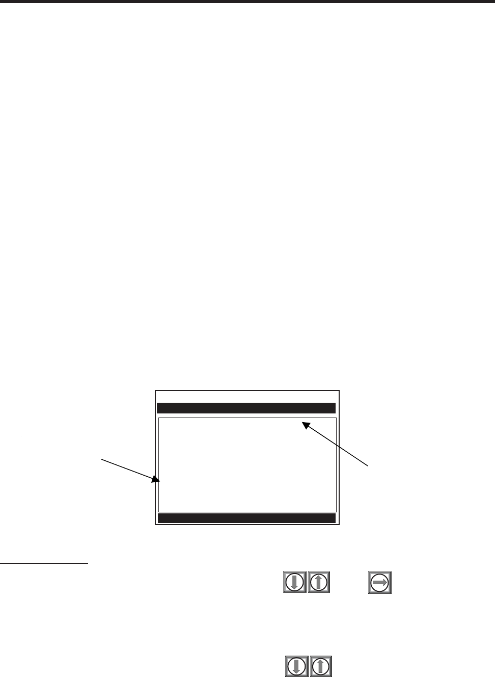
2-66
1010NFM-3JSection 2
To activate AnCal:
Move the cursor to the [AnCal ]menu cell by pressing . Press to enable numeric
entry. Note that an equal sign (=) appears before the number.
Type the desired flow rate using current rate units (e.g., 120.00 GPM). Note that the [Flow] menu
cell now reflects the artificial rate.
Move the cursor away from the menu cell by pressing to turn AnCal off.
HiFlow and LoFlow
The HiFlow and LoFlow menu cells allow you to enter maximum and minimum expected flow rates
based on current operating conditions. Under normal circumstances, you should never need to change
these settings. It is possible however, that a Controlotron customer service engineer may ask you to
edit these settings during a support session. In such a case, a <Right Arrow> at the menu cell enables
numeric entry.
Important Note: A caution on the use of upper and lower flow limits (used to prevent flow mis-registra-
tion) prior to using the Reversal Zero technique (Reversamatic): If the negative flow rate that the meter
reads in the step during which the transducers are reversed is more negative than the lower flow limit,
the meter will re-register positive and the Reversal Zero cycle will thus be corrupted.
Therefore, postpone the installation of upper and lower flow limits until the reversal zero procedure is
executed successfully. For pipes that combine large diameters with very high flow velocities, it may be
necessary to move the upper and lower flow limits out of the way until the reversal zero is completed.
Moreover, pipes of this size frequently have excellent intrinsic zero performance and may not even
need zeroing.
AnCal
This menu cell allows you to enter an artificial flow rate in current rate units that will drive the meter’s
analog outputs, totalizer output and the screen shown below. You can use AnCal to check the analog
outputs or as a reference source for calibrating external devices such as remote display screens or
chart recorders and RTU’s. To test the Totalizer function, leave AnCal active for enough time for an
accumulation to appear on the screen below. Moving the cursor from the menu cell cancels the AnCal
function.
Flow GAL/MIN 120.00
Flow Vel F/S 4.23
Total GAL 5645.820
Vs m/s 1274.33
Signal mV 44
Valc % 57
Vaer % 13
Alarm Status ------M--
AnCal GAL/MIN > 120.000
HiFlow GAL/MIN 1577.9
LoFlow GAL/MIN -1577.9
Siemens Dual Path SITE1
Flow Rate Simulation Control
Flow Data
The M status is
asserted due to the
method used to
simulate flow data.
Note that the [Flow]
menu cell immediately
reflects the AnCal entry.
Over time, the Total
display will also
increase.

2-67
1010NFM-3J
Section 2
2.11.3 THE APPLICATION INFO MENU
This menu provides a live display of the basic timing data used by meter during operation.
2.11.4 THE LIQUID DATA MENU
This menu shows the current Reynolds number used by the meter to implement flow profile compen-
sation. Depending on the 1010 model, Temp 1 & 2, Viscosity cP, Viscosity cS and Pressure are also
offered.
TN uSec 75.193
TL uSec 44.009
DeltaT uSec 126
Burst/Sec 256
% Accepted 100
Last Makeup (Re)Start
Makeup Status Measurement
Siemens 2 Channel [1] 1
Time between transit and receive
Application Info
Temp 1 Current Liquid Temperature
Temp 2 Current Liquid Temperature
Reynolds # Current Reynolds number
Specific Gravity Current specific gravity
Viscosity cP The absolute viscosity of a liquid dynamically measured in centipoise.
Pressure Derived spanned from analog input.
Viscosity cS Kinematic viscosity of a liquid measured in centistokes.
LIQUID DATA MENU ITEMS
APPLICATION INFO MENU ITEMS
TN uSec The total elapsed time between the transmission and reception of a sonic pulse.
TL uSec, The total time a sonic pulse takes to travel through the liquid.
DeltaT nSec This is the instantaneous result of subtracting the down from the up transit times.
NOTE: This will appear to be more active than dampened flow readings.
Burst/Sec Number of transmissions per second under current operating conditions.
The following factors influence this parameter: aeration, pressure transients,
signal strength variation.
% Accepted The running tally of accepted and rejected up/down transmit burst sets.
Last Makeup Reason for last Makeup (signal reacquisition).
Makeup Status Current stage of Makeup routine. [Measurement = normal operation]

2-68
1010NFM-3JSection 2
2.11.5 THE SITE SETUP DATA MENU
This menu provides data pertaining to transducer characteristics and operation. Some menu items
are for technical support interpretation only.
fx (drive) 30
N (burst length) 5
Ltn in -1.154
Vfmax GAL/MIN 1577.42
Vs max m/s 2165.41
Vs min m/s 936.62
Empty % 30
Samples/Cycle 16
Max Damping
Min Damping
HF 0.120
Siemens 2 Channel [1] Channel 1
Current transit drive code
Site Setup Data
Temp 1 78.5
Temp 2 50.0
Reynolds # 318017
Specific Gravity 1.000 S.G.
Viscosity cP 1.000 cP
Pressure 14.5 PSIA
Viscosity cS 1.000 cS
Siemens 2 Channel [1] Channel 1
Current Reynolds number
Liquid Data
fx (drive) Current Transmit drive code selected during Initial Makeup. The drive code
controls the sonic transmit signal.
N (burst length) Transmit burst duration selected during Initial Makeup. To change N count
press <Right Arrow>. At equal sign enter numeric value (1 to 9 only).
Ltn (in/mm) Spacing distance between the transducers. It will be in inches or millimeters,
depending on default units.
Vfmax The flow velocity (in selected units) corresponding to one whole cycle offset
between upstream and downstream receive signals.
Vs max m/s Maximum correctly calibrated Vs for current transducer spacing.
Vs min m/s Minimum correctly calibrated Vs for current transducer spacing.
Empty % Value of Empty Alarm Setting. The meter will declare an empty status if signal
strength drops below this value.
Samples/Cycle Digital sampling rate.
Max Damping Maximum signal damping. Use to average digital data when an unstable
condition occurs.
Min Damping Minimum signal damping. Use to average digital data when an unstable
condition occurs.
HF Flow registration correction parameter.
SITE SETUP MENU ITEMS

2-69
1010NFM-3J
Section 2
Introduction to [HF] Menu Item
All 1010 flowmeters with version 3.01.02 and later operating systems include a new Diagnostics Menu
item that permits the entry of a flow registration correction parameter labeled [HF]. This “HF” parameter
is the input for a proprietary algorithm which automatically compensates for signal beam blowing in
pipes utilizing either 1011 clamp-on or insert transducers, thereby extending the upper flow limit of all
1010 flowmeters. This algorithm provides the most benefit for clamp-on meters where high flow
velocities and low sound velocities create the most challenging conditions for digital signal processing
routines.
Using the [HF] Menu Item
Two methods for adjusting this parameter are provided via the [HF] menu cell, located within the
“Diagnostics / Site Setup” submenu. The “Manual” method provides direct entry of this parameter and
is primarily intended for the advanced user, whereas the “Automatic” method allows the 1010 flowmeter
to automatically measure the required correction and install the parameter.
Guidelines for using the [HF] menu item are described below:
zThis menu is only accessible for the transducer channels, not the virtual (average flow) channel
of the flowmeter. (i.e., Diagnostics Path 1 or Path 2, but not Path 1 & 2).
zThe 1010 flowmeter will inhibit the “Automatic” installation of the [HF] parameter if the flow rate
is insufficient (too low) to accurately measure the required correction. If the maximum flow
rate for the application is relatively low then this correction should not be required.
zIf the flow rate is very high and the flowmeter is reporting erroneous or unstable flow, then the
flowmeter may already be having trouble resolving the upstream and downstream signals. In
this event, it may be necessary to first lower the flow rate to a moderate level before performing
the “Automatic” HF adjustment. Once this is done the flowmeter should be able to properly
measure the highest flow rates without problems.
zThe limits of the “HF” parameter are +/- 0.7 and any attempt to manually install a larger value
will cause the flowmeter to abort the installation of the parameter.
NOTE: Pressing the <Left Arrow> at any stage prior to accepting the measured value will
abort the installation and return to the previous setting.
To access this [HF] menu item proceed as follows:
zAt the [Meter Type] Menu, press the <Right Arrow> and then <ENT> to select the desired Path
(e.g., Dual Path Flow).
zIn the [Dual Path Flow] Menu, press the <Down Arrow> and scroll to the [Diagnostic Data]
menu cell. Press the <Right Arrow> to select it.

2-70
1010NFM-3JSection 2
Siemens Dual Path 4SS10G
Access Path/Channel Diagnostic Data
Channel /Path Setup
Pipe Data
Application Data
Pick/Install Xdcr
Operation Adjust
Flow/Total Units
Data Span/Set/Cal
Stripchart Setup
Datalogger Setup
I/O Data Control
Diagnostic Data
Dual Path Flow
Siemens Dual Path 4SS10G
Transducer Setup Data
Path Select 1
Path Enable Yes
Flow Rate
Application Info
Liquid Data
Site Seup Data
Test Facilities
Print Site Setup No
Date Site Created: 04.09.0314.52.23
Diagnostic Data
“Manual” Adjustment Procedure
zIn the [Site Setup Data] Menu, press the <Down Arrow> and scroll to the [HF] menu cell. Press
the <Right Arrow> and a pop-up [Manual] prompt will appear as shown below. Note: Press the
<Up/Down Arrow> to select [Automatic], if desired.
zUse the numerical keys to input the desired correction value. Press <ENT> to input value.
fx (drive) 29
N (burst length) 5
Ltn in 5.316
Vf max CU Adjustment
Vs max m/s >Manual
Vs min m/s 1355.00
Samples/Cycle 29
HF >-0.000
Siemens Dual Path 4SS10G
Site Setup Data
fx (drive) 29
N (burst length) 5
Ltn in 5.316
Vf max CU >Manual
Vs max m/s = -0.120
Vs min m/s 1355.00
Samples/Cycle 29
HF >-0.000
Siemens Dual Path 4SS10G
Site Setup Data
zIn the [Diagnostic Data] Menu, highlight [Path Select] and select the desired transducer path.
Press <ENT> to select path.
zPress the <Down Arrow> and scroll to the [Site Setup Data] menu cell. Press the <Right
Arrow> to select it.
zThe new correction value will appear next to the [HF] menu cell as shown below.

2-71
1010NFM-3J
Section 2
fx (drive) 29
N (burst length) 5
Ltn in 5.316
Vf max CU
Vs max m/s
Vs min m/s 1355.00
Samples/Cycle 29
HF >-0.120
Siemens Dual Path 4SS10G
Site Setup Data
“Automatic” Adjustment Procedure
zIn the [Site Setup Data] Menu, press the <Down Arrow> and scroll to the [HF] menu cell. Press
the <Right Arrow> and a pop-up [Manual] prompt will appear.
zPress the <Up or Down Arrow> to select [Automatic] then press <ENT>.
zThe current measured correction value is displayed (see below).
zPress <ENT> again to install this correction value which will now appear next to the [HF] menu
cell.
NOTE: The value shown in the [Automatic] pop-up prompt can not be changed and is for user
information only.
fx (drive) 29
N (burst length) 5
Ltn in 5.316
Vf max CU Adjustment
Vs max m/s >Automatic
Vs min m/s 1355.00
Samples/Cycle 29
HF >-0.000
Siemens Dual Path 4SS10G
Site Setup Data
fx (drive) 29
N (burst length) 5
Ltn in 5.316
Vf max CU >Automatic
Vs max m/s = 0.026
Vs min m/s 1355.00
Samples/Cycle 29
HF >-0.026
Siemens Dual Path 4SS10G
Site Setup Data
zIf you decide not to use the [Automatic] selection, press any key other than <ENT> to abort the
operation.
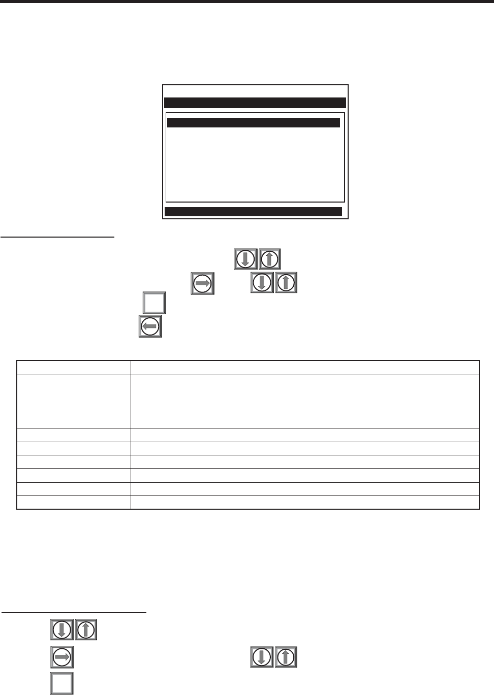
2-72
1010NFM-3JSection 2
2.11.6 THE TEST FACILITIES MENU
The Test Facilities menu provides commands for system analysis and recovery. The most useful for
the end-user are Makeup and Graph. Using these routines under the supervision of our technical
support staff will help us to provide technical analysis and solutions.
To start a Test Routine:
To scroll the cursor to the test routine press
To access the test option list press . Press to move the asterisk to [Yes].
To start the routine press
To end the routine press
ENT
Makeup
The Test Facility Makeup routine allows you to command the meter to re-acquire the operating param-
eters established during the Initial Makeup routine invoked by the [Install Completed?] command (see
paragraph 2.4 Pick/Install Xdcr Menu).
To invoke the Makeup routine:
Press to scroll the cursor to [Makeup].
Press to access the test option list. Press to move the cursor to [Yes].
Press to start the makeup routine.
ENT
Makeup No
Graph No
Tx Up No
Tx Dn No
Fixed ALC No
Tx Up Fixed ALC No
Tx Dn Fixed ALC No
Graph AutoZero No
Siemens 2 Channel [1] Channel 1
Right arrow invokes an InProcess Makeup
Test Facilities
Makeup Commands the meter to re-acquire the receive signal.
Graph Enables an on-screen signal display. To access graph parameters,
press <Right Arrow>. Select [Yes]. Press <ENT>. Scroll and press
<ENT> to select parameter(s). Press <Left Arrow> to return to graph
and view selected parameters.
Tx Up Forces upstream transmission only.*
Tx Dn Forces downstream transmission only.*
Fixed ALC Select [Yes] to command amplifier to hold a constant gain.*
TX Up Fixed ALC Fixed ALC while transmitting up only.*
TX Dn Fixed ALC Fixed ALC while transmitting down only.*
Graph AutoZero Waveform of the ZeroMatic signal reference.
* For technical service diagnostics.
TEST FACILITIES COMMANDS
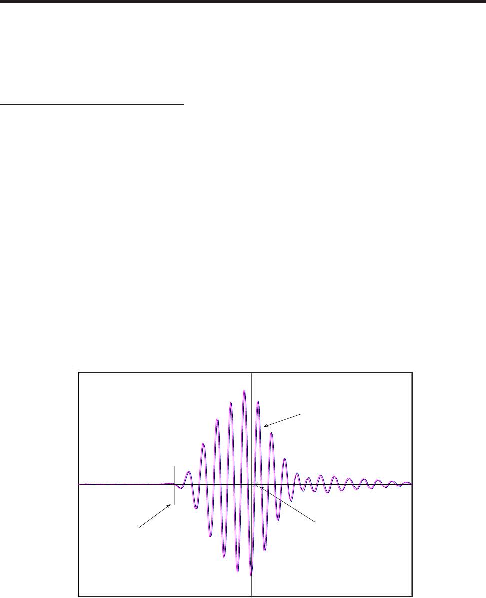
2-73
1010NFM-3J
Section 2
Detection Mode
System 1010 flowmeters, Version 3 or higher, are equipped with a Test Facilities Graph Screen. The
following paragraphs explain how the Test Facilities Graph Screen is used for troubleshooting System
1010 flowmeters.
The Test Facilities Graph Screen
NOTE: The following is intended for 1010 VFMT systems with Graphic Displays only. For VFMT
capable 1010X systems (with or without digital displays) or 1010N blind systems, the
digital receive signal can only be viewed as a text dump over the RS-232 output (i.e.,
by pressing the <F1> key and then the period key <.>). Access to the digital damping
parameters can be found in the [Site Setup] menu cell of the Diagnostic Data menu.
Refer to the appropriate System 1010 field manual for details.
When operating in the transit time mode the Test Facilities Graph Screen is an exceptional diagnostic
tool for troubleshooting problem applications or simply determining receive signal quality. The primary
function of this screen is the display of the digitized receive signal waveform with similar appearance
and function of a digital oscilloscope. This screen also allows the user to override some of the 1010
default settings by permitting adjustment to the measured transit time, the digital averaging and the
zero crossover used in the measurement of the up/down transit time difference. The figure shown
below is a representation of the 1010 diagnostic graph.
NOTE: The Test Facilities Graphic Screen requires significant CPU overhead. The 1010 meter
should not be left in this mode during normal operation, where the Datalogger is the
primary output, or during calibration work.
F 0.73
VS 1469.73
[ ] 1691:1929 476
D 4:4 4
Tn 55.06 55.06
dT 3.11
S 72 1
SN 124:1
CQ 17:1
Digitized Receive Signal
TN marker Crossover Marker
Command Line appears here
91
3

2-74
1010NFM-3JSection 2
Entering the Diagnostic Graph Screen
Before you can view the Diagnostic Graph Screen the 1010 flow channel must first be properly in-
stalled and operating in a non-empty condition (refer to the appropriate 1010 Field manual). If a previ-
ously installed channel is in a “Fault” condition, but not reporting “Empty”, you can still access the
Graph Screen to aid in troubleshooting the cause of the failure to measure flow.
To view the Graph Screen first enter the [Test Facilities] menu, which is a submenu of the main [Diag-
nostic Data] menu.
zPressing the <Up/Down Arrows>, scroll to the [Graph] menu item.
zPress the <Right Arrow> to enter the [Graph] menu and scroll to highlight the [Yes] item in the
option list.
zNow press the <ENT> key to access the Graph Screen.
zTo exit the Graph Screen and return to the main menu, press the <MENU> key once.
Diagnostic Text Display
The text to the upper left-hand corner of the screen represents diagnostic items which can be individu-
ally turned on or off to reduce unnecessary clutter on the screen. This text display can be modified by
pressing the <ENT> key and scrolling up or down through the various parameters that appear in the
Graph Display menu. Pressing the <ENT> key will select the highlighted parameter (a “+” sign appears
next to selected items) and pressing <CLR> will deselect the item. Pressing the <Left Arrow> will
return you to the graph screen with the selected parameters appearing at the top left corner of the
screen. (The figure above is shown with all diagnostics items selected).
Time Base Control
The digitized receive signal can be moved either to the left or right on the screen by pressing the <Left>
or <Right> keypad arrows. The direction of the arrow actually represents the direction in which the
receive “window” will move, thereby causing the receive signal to shift in the opposite direction on the
screen (e.g., Pressing the <Left Arrow> moves the signal to the right).
The digitized receive signal can be expanded or contracted in the time domain by pressing the <+> or
<-> keys on the keypad. This allows you to see the entire contents of the receive window, or zoom in to
see greater detail. Pressing the <CLR> key once will automatically center the receive signal on the
screen. When zooming in on the receive signal small vertical “tick” marks may appear. These marks
represent the time at which the receive signal is digitally sampled.
Correlated Plot
During conditions of flow, the actual transit time delta (difference) can be observed in the displayed
receive signal waveform when the [Correlated Plot] menu parameter is not selected. To observe this
time difference simply depress the <+> key (to see greater signal detail) until the individual up and
down receive signals are clearly discernible. To verify that the 1010 signal processing algorithms are
properly correlating the up and down stream receive signals, select the [Correlated Plot] option from
the display menu list.

2-75
1010NFM-3J
Section 2
Return to the graph screen and observe the relative position of the up and down waveforms. In a
properly correlated receive signal the two images should be nearly superimposed on top of each other,
even during high flow conditions. In the unlikely situation where the two images appear to be offset by
one or more receive cycles then the flow readings should be considered questionable.
Command Modes
Although the 1010 signal processing algorithms are capable of accommodating a very wide range of
signal conditions, it may be desirable to override these default settings under extremely difficult operat-
ing conditions. The following functions are available for this purpose:
Digital Damping Control: (Hot Key 1 and 2)
The 1010 permits user modification of the digital averaging used by the signal processing routines. In
general, the default damping values selected by System 1010 will provide optimal performance over a
wide range of transit time applications. However, in extreme cases of unstable flow profile, low signal
levels or high aeration it may be necessary to override these default settings to permit uninterrupted
and reliable flow measurement.
The 1010 Graph Screen includes the capability to access a set of command codes, which enable a
user to override a number of default setup parameters. The most important parameter is the digital
damping control, which can be accessed by pressing number <1> or <2> on the keypad while in the
graph screen mode.
Pressing the <1> key will cause [MinDamp #] to appear on the command line at the lower left-hand
corner of the screen. The number listed to the right of the command code represents the exponent in
the System 1010 exponential averaging routine, where the larger the number the greater the digital
averaging. Pressing the <+> key will increase the damping value. Likewise, pressing the <-> key will
decrease the damping value. To exit this mode, press the <0> key on the keypad.
Pressing the <2> key will bring up the [MaxDamp] command. The function of this parameter is similar
to the [MinDamp] command described above, however, the two parameters interact in the following
manner. The MinDamp value must not exceed the MaxDamp value, therefore increasing the MinDamp
value above the previous MaxDamp value will set both parameters to the same value. In most cases,
it is preferred that both damping parameters be set to the same value, however, in cases where rapid
response to changes in liquid sound velocity is required, the two values may be set differently. In this
situation the meter will use the MaxDamp value when sound velocity is stable, but then switch to a
faster damping value (limited by MinDamp) when a significant change in sound velocity is perceived.
To exit this mode, press the <0> key on the keypad.
Transit Time Adjustment: (Hot Key 3)
Observe the short vertical marker at the beginning of the receive signal in the Graph Screen above.
This line represents the position in time (Tn) where the 1010 flowmeter perceives the arrival of the
ultrasonic signal. There are actually two Tn markers, one for the upstream arrival time and one for the
downstream arrival time. For proper liquid sound velocity measurement these Tn markers should be
positioned near the beginning edge of the receive waveform envelope (as shown), however, in cases
of poor signal conditions it is possible for this measurement to be off by several receive waveform
cycles.
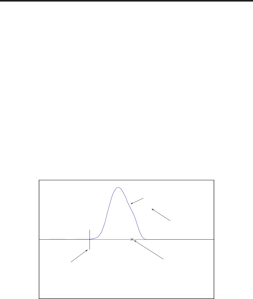
2-76
1010NFM-3JSection 2
To adjust the Tn mark position press the <3> key on the keypad to bring up the [TnSet] command.
Pressing the <+> or <-> keys will cause the Tn marker to move later or earlier, respectively. The
change from the default value (in samples) will appear in the number to the right of the command. As
you adjust the Tn marker, both Tn and Vs (liquid sound velocity) will change accordingly. To exit this
mode, press the <0> key on the keypad.
Zero Crossover Adjustment: (Hot Key 4)
Observe the small “X” mark located on the zero crossing line near the middle of the receive signal in
the Graph Screen above. This “X” indicates the central crossover which the 1010 is using to measure
the transit-time delta. This crossover will generally be close to the peak of the receive signal with at
least one well formed (non-aberrated) receive cycle on each side of the crossover. If it appears that the
placement of this crossover is unsatisfactory then it can be adjusted by pressing the <4> key on the
keypad, which will invoke the [ZCOSet] command. The crossover point can then be moved in either
direction on the waveform using the <+> or <-> keys. The change from the default value (in receive
cycles) will appear in the number to the right of the command. To exit this mode, press the <0> key.
Envelope Threshold Adjustment: (Hot Key 5 & 6)
Pressing the <=> key causes the graph to toggle between the default signal waveform screen and the
signal envelope screen (see example below). This envelope screen can aid in the diagnosis of Tn
errors caused by unusual receive waveform distortion. Signal distortion is sometimes caused by poor
transducer selection or poor pipe wall conditions, which may result in an incorrectly measured fluid
sound velocity. To improve the automatic measurement of Tn, the envelope threshold limit can be
adjusted to exclude portions of the envelope, which may be causing the Tn detection problem.
F 0.73
VS 1469.73
[ ] 1691:1929 476
D 4:4 4
Tn 55.06 55.06
dT 3.11
S 72 1
SN 124:1
CQ 17:1
Envelope Signal
TN marker Crossover Marker
Command Line appears here
Envelope Threshold
91
3
HiSet
If it appears that the default placement of the Tn marker is incorrect or unstable, it can be adjusted by
pressing the <5> key on the keypad to invoke the [EnvSet] command (while viewing the envelope
screen). A horizontal line representing the envelope threshold level will appear along with a number
indicating the percentage level. The High and Low thresholds can then be moved either up or down on
the envelope using the <+> or <-> keys. While viewing the Tn marker position, adjust the thresholds so
that they are well above the baseline “noise” level but below the first major peak. To exit this mode,
press the <0> key.

2-77
1010NFM-3J
Section 2
Signal Masking Function: (Hot Key 7)
Under conditions of extremely low signal amplitude, a noise spike associated with 1010’s receive
signal window may be present on the extreme left side of the graph display. If this spike is large enough
it may interfere with the signal detection routines. To eliminate this noise from the signal processing
routines, press the <7> key to invoke the [MaskSet] command, then press the <+> key until the noise
is no longer present in the receive waveform. Press <0> to exit this command.
Screen Text
Parameters Menu List item Description
F Flow Measured flow rate in selected flow units.
VS Vs (m/s) Sound Velocity in meters per second.
[ ] Display Metrics Represents the digital sample position of the receive window.
Correlated Plot Displays the receive waveform in its proper superposition or registra-
tion. The true delta time will be displayed by NOT selecting “Corre-
lated Plot”.
Centroid Mark Indicates with a large vertical marker the peak energy of the receive
waveform.
D Damping Displays the minimum and maximum digital damping exponent along
with the active damping exponent.
Tn Tn (usec) Receive signal transit time in microseconds.
dT Delta T (nsec) Transit time delta (difference) in nanoseconds.
S Signal Strength Displays %Valc (amplitude), %Vaer (aeration factor) and numeric ALC.
SN Signal to Noise Ratio Indicates the signal to noise ratio of the receive signal. Increased
damping will increase the S/N ratio as the asynchronous noise re-
duces.
Envelope Signature Percentage change of the signal from Initial Makeup conditions.
DESCRIPTION OF GRAPH SCREEN TEXT DISPLAY PARAMETERS
Key Command Line Description
<+> Expands (magnifies) waveform to view more detail.
<-> Contracts waveform to view more or the waveform.
<Left Arrow> Shifts receive window to the left (waveform to the right).
<Right Arrow> Shifts receive window to the right (waveform to the left).
<CLR> Brings waveform to the center of the screen.
<ENTER> Calls up Text Display menu items. <Left Arrow> to return to graph.
<MENU> Exits the Graph Screen and returns to the main menu.
<1> MinDamp Minimum damping exponent control (+ or - to increase or decrease).
<2> MaxDamp Maximum damping exponent control (+ or - to increase or decrease).
<3> TnSet Transit time adjustment (use + or - to move Tn marker).
<4> ZCOSet Zero Crossover adjustment (use + or - to move crossover marker).
<5> HiSet Signal envelope threshold level (use + or - to move threshold).
<6> LoSet Signal envelope threshold level (use + or - to move threshold).
<7> MaskSet Leading edge masking functions (use + or - to alter number of samples
masked).
<8> Hold Set Set this number higher if intermittant mis-registration occurs.
<0> Exits the command line.
<=> Toggle graph between receive waveform and envelope waveform.
<F1> and <.> Dumps the digitized waveform data over the RS232 port. You must first
leave the Graph Screen mode before invoking this command.
HOT KEY SUMMARY

2-78
1010NFM-3JSection 2
(continued)
2.11.7 TROUBLESHOOTING TIPS
The System 1010 has highly reliable circuitry and will provide trouble-free operation within specified
environments. Even a well-crafted precision instrument can fail if exposed to extreme temperature or
vibration conditions during service, storage or transportation. The Diagnostic menu shows how the
system interprets a problem. The test functions and alarm indicators identify “hidden” problems auto-
matically. If a problem seems unsolvable, call our Technical Service Department or your local Siemens
Ultrasonic Flow Representative for expert help.
Flow Computer Messages
Certain actions or conditions invoke messages that may appear as a pop-up window, in the right-hand
column of a given menu cell, or the highlighted prompt line at the top of the display screen. The follow-
ing is a list of messages that you may encounter along with explanations, and in some cases, a recom-
mended action.
MESSAGE DESCRIPTION
Memory Full! Response to an attempt to save site data, when data memory is full. Delete
an obsolete site or clear Datalogger memory to make room for the new
data.
Memory Corrupted! Memory read error occurred while accessing the active site data.
Chan Not Setup Response to an attempt to invoke an operation that requires a channel to
be enabled. Enable the channel [Channel Setup Channel Enable Yes].
Note that a channel cannot be enabled until its transducers are operating.
Clr Active Memory? Response to pressing the F4 key. Use the F4 function to restore operation
if a severe event (e.g., a violent power surge) disrupts system operation.
Clr Saved Data? Response to pressing the F4 key, then selecting [No] for Clr Saved Data?
Yes/No
<EOT> Response to a request to output datalogger data to the printer or the Graph-
ics screen when no datalogger data exists. Set up the Datalogger.
Empty Pipe - Press Prompt to empty the pipe during the Actual MTY procedure. After emptying
pipe, press <ENT>.
Fill Pipe - Press [ENT] Prompt to fill the pipe during the Actual MTY procedure. After filling the pipe,
press [ENT] (see paragraph 3.1.3).
No Sites Response while trying to recall/delete a site setup when no Sites are stored.
Not Installed Response to an attempt to access a menu function that is not included.
Re-space Index Upon measuring the liquid sonic velocity (Vs), the meter recommends re-
spacing the transducers to improve performance.
Invalid Setup During the Initial Makeup, the system detects invalid transducer spacing,
erroneous liquid/pipe parameters, or some other factor that prevents it from
completing the Initial Makeup. This may be due to one of the following:
• An out-of-range data entry.
• An invalid condition (e.g., overlapping transducers in Reflect Mode). If se-
lecting Direct Mode does not resolve, review all site setup and transducer
installation choices; particularly data entered for the pipe and liquid.
(use Direct Mount)
[ENT]

2-79
1010NFM-3J
Section 2
NOTE: If you receive a Detection Fault message, it is strongly recommended that you con-
tact Technical Service for further orientation.
Using the “F4” Reset Sequence
You may encounter an operating problem that blocks access to the Diagnostics Menu, or the meter
may operate erratically after exposure to a power transient or some other traumatic event. These
cases may require use of the F4-reset sequence to restore operation.
The F4-reset sequence operates on two levels. The first F4-reset deletes all the data currently in Active
Memory, but leaves Datalogger data and all stored Site Setups intact. This is the most desirable method
since all you have to do to restore operation is reload a saved Site Setup. If this fails then you have to
resort to the second level of the F4 sequence, which allows you to clear ALL Dynamic Memory. Be
aware that this erases all saved Site Setups (including flow calibrated sites), Datalogger Data and
user-defined pipe and transducer tables. This will require you to completely re-install the system and
repeat all desired default settings, custom pipe tables, etc. The chart on the next page shows the
sequence of the [F4] routine.
• In Reflect Mode, the flow computer detects that the pipe wall signal may
infringe upon the liquid signal. Use Direct Mode instead.
Press <ENT>, <UP Arrow>, <DOWN Arrow>, or <LEFT Arrow> to abort
install routine. Continue programming other site data in anticipation of re-
solving the difficulty later. Call technical support for help if necessary.
Low Signal - Press During the Initial Makeup, the meter decides that the level of the receive
signal is insufficient for proper operation. Some reasons for low signal are:
• Invoking [Install Completed?] on an empty pipe.
• Coupling compound insufficient, not applied, or evaporated.
• A disconnected or broken transducer cable.
• You need to condition the pipe at the mounting location.
• Flush out Large air bubbles.
• The Xdcr cables are defective or not connected to the correct channel.
• The Set Empty routine performed when pipe was NOT actually empty.
Detection Mode If you locate and correct the improper condition immediately, press <ENT>
to resume the installation procedure. Otherwise, press the <LEFT Arrow>
to abort the installation and conduct a thorough investigation.
Appears if the meter cannot complete an Initial Makeup. It means that the
pipe and/or liquid conditions do not permit a receive signal that meets the
flow detection standards. The system will not be able to operate. Attempt to
improve operating conditions by reinstalling the transducers at a different
spacing offset, or even at a different location on the pipe.
In addition, switching from Reflect to Direct Mount may solve the problem.
However, operation may not be possible if there is poor liquid or pipe wall
sonic conductivity or extreme liquid aeration.
MESSAGE DESCRIPTION
[ENT]
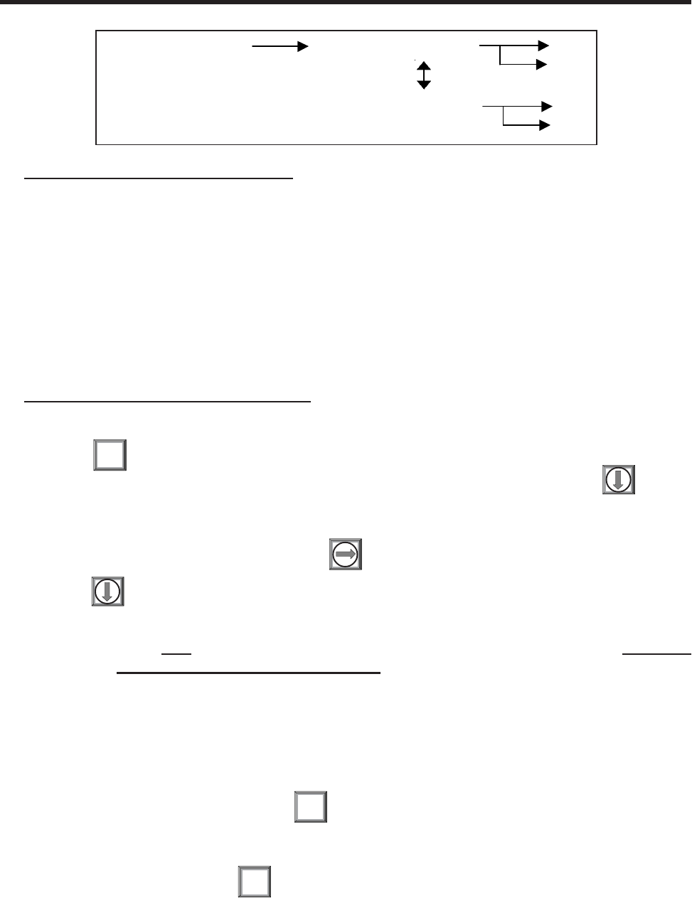
2-80
1010NFM-3JSection 2
Procedure to clear Active Memory only:
Turn off power (if it is currently on). Press <F4> and keep it pressed while you turn on power.
The prompt: [Clr Active Memory? No] appears at the top of the screen.
Press <Right Arrow> to access F4 Reset option list. Press <Down Arrow> to switch the option
list to [Clr Active Memory? Yes]. Press <ENT> to clear all Active Site Data (but not saved Site
Setups).
To restore operation, press <MENU> to access the installation menu. Create a new site setup
or recall a stored site setup.
Re-select any Meter Facilities items (e.g., RS-232 setup parameters).
Procedure to clear ALL Dynamic Memory:
Turn off power (if it is currently on).
Press and keep it pressed while you turn on power.
The prompt: [Clr Active Memory? No] appears at the top of the screen. Press .
Note that the prompt switches to [Clr Saved Data? No].
To access the F4 Reset option list press .
Press to switch the option list to [Clr Saved Data? Yes].
CAUTION: Before proceeding further it is essential to understand that this function elimi-
nates ALL data stored in RAM. This means that all saved site setups including
the site data of a flow-calibrated site will be erased! In addition, the entire Data-
logger file plus any custom factory or user-created pipe or transducer tables
will be eliminated. The impact of this is such that we strongly recommend that
you consult technical service before continuing with this procedure. Be aware
that you will have to create a new Site Setup, re-enter all site specific param-
eters including pipe or transducer tables, plus all desired Meter Facilities en-
tries.
To clear all Dynamic Memory press
Create a Site Setup before attempting to access other menu items.
To restore operation, press to access the installation menu. Create a new site
setup and complete the installation procedure.
Re-select desired Meter Facilities items (e.g., RS-232 setup parameters).
F4
ENT
MENU
[Power On/Off + F4] [Clr Active Memory?] No
Yes
[Clr Saved Data?] No
Yes
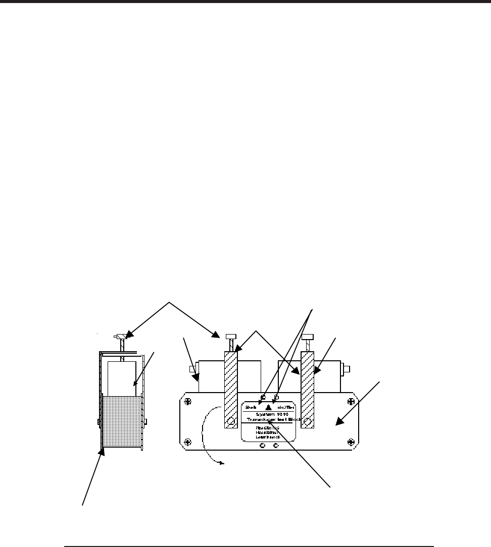
2-81
1010NFM-3J
Section 2
2.11.8 TROUBLESHOOTING WITH TRANSDUCER TEST BLOCKS
To resolve an apparent system malfunction, you have to determine whether the problem is due to
equipment failure or an application condition. Our 1012 and 996 Transducer Test Blocks allow you to
bench test the flow computer, transducers and their cables. If the system operates properly using the
test block, then focus on application conditions as the source of the problem. Series A and B 1011
transducers use the 1012TB-1 Test Block and series C and D use the 1012TB-2 Test Block. At the
present time, neither one support the 1011 High Precision transducers.
The 996PSP-pipe simulator allows you test a 1010 series flow computer and 991 transducers from
size 0 to size 3. Note that although the 1010 flow computer operates with our 991 size 4 and 5 trans-
ducers, testing of these sizes with a 1010 flow computer is not currently supported.
2.11.9 USING THE 1012TB-1 AND 2 TEST BLOCKS
The 1012TB-1 and 1012TB-2 test blocks provide two test surfaces. Each surface supports a specific
transducer size. For example, one surface of the 1010TB-1 supports Size “A” transducers and the
other supports Size “B” transducers. The 1012 pipe simulators include two labels, one on each side-
plate. The labels identify the transducer size, data to be entered, and the surface to be used with the
specific transducer size. See drawing on next page.
1. Identify the side of the simulator that applies to the transducers under test. Rotate the clamping
bracket as required to mount transducers on the test surface.
2. Using a coupling compound (preferably CC-102), mount the transducers on the pipe simulator as
shown above. Slide each transducer until it presses against the pin-stop. Use the clamping screws
to hold the transducers in place.
3. Connect transducer cables between each transducer and the meter connectors for the channel
under test. The Up and Down orientation is not important.
MOUNTING TRANSDUCERS ON A 1012 TRANSDUCER TEST BLOCK
Transducer clamping
screw
Transducer testing
surface for an A
size transducer
Slide transducers firmly against
Transducer Pinstops
Transducer
under test
Transducer
under test
Transducer
Clamping
Bracket
Example shows testing for
size B. Rotate brackets 180 to
mount SizeA transducers
This label shows the
data entry parameters
for size B. Size A
parameters appear on
a label on the other
side plate
This arrow points to
the surface associated with the
xdcr size identified on the label
2-82
1010NFM-3JSection 2
7. Access the [Pick/Install Xdcr] menu. Check the [Transducer Size] menu cell. If necessary, enter
the Xdcr Size option list and pick the transducer under test.
8. Check the [Xdcr Mount Mode] menu cell. Adjust to match the simulator chart above.
9. Move the highlight down to [Install Completed?] by pressing . Access the option list. To move
the cursor to [Install] press . Press to start the transducer install routine.
ENT
NOTE: Since Sizes A and C transducers are installed in Reflect Mode, you will see a pop-up
window that prompts you to: [Use Actual Zero]. You can ignore this by pressing the
<Down Arrow>.
Upon the completion of the [Install] procedure, the flow computer should report a sonic velocity within
the range of approximately 1350m/s to 1700 m/s (depending on the transducer size under test). Next,
check [Diagnostic Data] menu. The [Valc %] item must be >35 for dependable operation. In addition,
note the reading, then compare it to the [Vfmax] item in the [Diagnostic Data/Site Setup Data] menu.
The value of the reading should be less than 2% of the published Vf max.
Confirming these values certifies that the entire system (computer, transducers, cables) is operating
correctly. The investigation should proceed to a review of all site conditions to locate the operating
problem.
4. Access the Installation Menu. Select [Meter Type] [Single, Dual or Quad Channel] depending on
meter type. Select the meter channel (1,2,3, or 4) depending on which measurement channel you
intend to test. Select [Clamp-On] and then [Channel Setup].
5. Access the [Channel/Path Setup] menu. Move the highlight to [Create/Name Site]. Create a new
Site Setup (e.g., TEST1). You can now enter data without altering an existing Site Setup.
6. Select the [Pipe Data] Menu. Referencing either the English or metric pipe simulator chart below,
enter the pipe data corresponding to the transducer size under test.
Part Xdcr Pipe OD Pipe Wall Mount Spacing Number
Number Size (in.) Mat’l Thk (in.) Mode Offset Index
1012TB-1 A 0.650 Steel* 0.100* Reflect Nominal 7
1012TB-1 B 1.150 Steel* 0.100* Direct Minimum 4
1012TB-2 C 2.000 Steel* 0.100* Reflect Nominal 11
1012TB-2 D 3.500 Steel* 0.100* Direct Minimum Use Ltn
*System Defaults
1012TB-1 & 2 Universal Transducer Test Block Chart (English)
*System Defaults
Part Xdcr Pipe OD Pipe Wall Mount Spacing Number
Number Size (mm) Mat’l Thk (mm) Mode Offset Index
1012TB1 A 16.5 Steel* 2.54* Reflect Nominal 7
1012TB1 B 29.2 Steel* 2.54* Direct Minimum 4
1012TB2 C 50.8 Steel* 2.54* Reflect Nominal 11
1012TB2 D 88.9 Steel* 2.54* Direct Minimum Use Ltn
1012TB-1 & 2 Universal Transducer Test Block Chart (Metric)

2-83
1010NFM-3J
Section 2
2.11.10 USING THE 996PSP PIPE SIMULATOR
Using the proper coupling compound, mount the transducers on the pipe simulator as shown below.
Slide each transducer until it presses against a pin-stop. Use the clamping screws to hold the trans-
ducers in place.
To mount transducers on a 996PSP Pipe Simulator
1. Using coupling compound, mount the transducers on the pipe simulator as shown on the previous
page. Slide each transducer until it presses against a pin-stop. Use the clamps to hold the trans-
ducer in place.
2. Connect cables between each transducer and the computer connectors for the channel under test.
The Up and Down orientation is not important.
3. Access the Installation Menu. Select [Meter Type] [Single, Dual, or Quad Channel] depending on
meter type. Select the meter channel (1,2,3, or 4) depending on the measurement channel you
intend to test. Select [Clamp-on] and then [Channel Setup].
4. Access [Channel/Path Setup] menu. Move highlight to [Create/Name Site]. Create a new Site Setup
(e.g., TEST1). You can now enter data without altering an existing Site Setup.
5. Select the [Pipe Data] Menu. Referencing either the English or metric pipe simulator chart below,
enter the pipe parameters corresponding to the transducer size under test.
Part Xdcr Pipe Pipe Wall Mount Letter Number
Number Size OD (in) Mat’l Thk (in) Mode Index Index*
996PSP-0 0 2.420 PVC 0.076 Direct A 6
996PSP-1 1 2.481 PVC 0.077 Direct A 9
996PSP-2 2 2.743 PVC 0.136 Direct A 6
996PSP-3 3 3.758 PVC 0.344 Direct A 1
996PSP-4 4 6.500 PVC 1.000 Direct** A 0
996PSP PIPE SIMULATOR CHART (English)
* The flow computer generates the Number Index.
** See note below.
Clamping Screw
Xdcr
Clamping
Bracket
991 Transducers
Under test
Pipe Simulator
Transducer
Pinstops
Xdr
Clamping
Bracket
Clamping Screw 991 Transducers
Under Test
Transducer
Pinstops

2-84
1010NFM-3JSection 2
NOTE: When using a 996PS-4 Simulator, you must access the [Application Data] menu, select
[Liquid Type] - [Other], then program the [Estimated Vs] for a value of 2100 m/s.
6. Access the [Pick/Install Xdcr] menu. Access the [Transducer Model] menu cell. Enter the Trans-
ducer Model option list. Select [991 Universal].
7. Check the [Transducer Size] menu cell. If necessary, enter the Transducer Size option list and pick
the actual transducer under test.
8. Check the [Xdcr Mount Mode] menu cell. Adjust as necessary to match the simulator chart above.
9. Move the highlight down to [Install Completed?]. Access the option list. Move the cursor to [Install].
Press <ENT> to start the transducer install routine.
10. Check to make sure that the flow computer returns the Number Index listed in the chart above.
Next, review and verify the Diagnostics data items as described previously. If the computer, cables
and transducers are operating properly, then review all site conditions to locate the operating prob-
lem.
If a Pipe Simulator/Test-Block Test Fails:
1. Replace the transducer cables. If this allows you to complete the test as described above, then the
cables were defective.
2. If the cables are proven to be good, replace the transducers on the pipe simulator with a “known
good” set. If the system functions properly, then the original transducers under test are defective.
Please return any defective transducers to Siemens for repair.
3. If you replace the transducers and cables, and the system still fails to function correctly, then it is
likely that the computer has a malfunctioning circuit module. If you have spare modules you may try
module substitution to identify the defective module. Otherwise, please call our Technical Service
Department for further instructions.
* The flow computer generates the Number Index.
** See note below.
Part Xdcr Pipe Pipe Wall Mount Letter Number
Number Size OD (mm) Mat’l Thk (mm) Mode Index Index*
996PSP-0 0 61.47 PVC 1.93 Direct A 6
996PSP-1 1 63.02 PVC 1.96 Direct A 9
996PSP-2 2 69.67 PVC 3.45 Direct A 6
996PSP-3 3 95.45 PVC 8.74 Direct A 1
996PSP-4 4 165.1 PVC 25.4 Direct** A 0
996PSP PIPE SIMULATOR CHART (Metric)

2-85
1010NFM-3J
Section 2
2.12 GUIDE TO A SMOOTH INSTALLATION
NOTE: The following should be used in conjunction with the System 1010 Field Manual
Diagnostic and Troubleshooting procedures.
2.12.1 CHECKLIST FOR 1010 STARTUP & PERFORMANCE
PROGRAMMING
Select appropriate meter type: Clamp-On, Reflexor, Dual Beam, Flow Tube, etc.
Select proper channel (Dual or Multi-Channel Systems Only).
Use “Full Site Setup”
Create Site (or Recall Site).
Program accurate Pipe Diameter, Material & Wall Thickness (or choose from tables).
Program accurate Liner Material and Thickness (if applicable); Ensure Liner is well bonded.
Program correct Liquid Type (Estimated Vs), Consult Vs Database for liquids not on meter menu.
Select Recommended Transducer, HP for Steel Only; Use first choice for Universals, if possible.
Ensure Transducer Type & Size match programming.
Ensure transducer serial numbers match each other.
INSTALLATION/TRANSDUCER MOUNT GUIDELINES
Install Transducers (Reflect/Direct) as recommended by meter; Use assigned spacing positions!
Use Reflect Mount whenever possible (Not permitted on plastic pipes).
Avoid placing transducers downstream of flow obstructions, pressure drops, elbows.
Mount upstream of Orifice Plates, Turbines, Valves, “T’s”
Allow a minimum of 10 diameters of straight pipe upstream of Transducers; More following multi
elbows.
If <10 diameters is available, mount Reflect within 2 diameters, in Plane-of-Elbow (on outside of
bend).
DO NOT mount Transducers on top and/or bottom of horizontal pipe!
Ensure pipe is clean and smooth; remove external scale, loose or flaking paint.
Use appropriate Coupling Compound for application (see charts below).
Avoid mounting on pipe seams.
Connect “UP” Cable to “Upstream Transducer” (closest to source of flow) and vice versa.

2-86
1010NFM-3JSection 2
START-UP
Ensure pipe is FULL (flowing or not).
Select “Install Complete?”…..INSTALL to Invoke “Initial Makeup” routine.
Verify “Measured Vs” is accurate for liquid type & temperature (Consult Vs Database)
Set Zero appropriately (AutoZero or ZeroMatic for Reflect, Actual Zero or ReversaMatic for Direct).
After completion of Zeroing, access Flow Display by pressing <MENU> key.
Use <UP/Down Arrows> to scroll through available displays.
Verify Vs is correct for Liquid and Temperature.
Verify Valc is Greater Than 30.
Verify Vaer is Less Than 10 when flowing.
Check Signal Graph Trace to be acceptable. See reference graph below.
For 1011 Universal Transducers verify “VfMax” is higher than maximum Flow Rate of application.
Set “Hi Flow” at 90% VfMax; Ensure it is higher than Max Application Flow Rate.
Set “Lo Flow” at –10% VfMax. (For unidirectional flow applications only!)
Set “Lo Flow” at 10% Greater Than Maximum Negative Flow (Bi-Directional Applications).
DIAGNOSTIC/PERFORMANCE VERIFICATION
2.12.2 OPTIMIZATION/CORRECTION OF PROBLEMS
Incorrect “Measured Vs”
Verify actual pipe (outside) diameter matches meter programming.
Verify actual Wall Thickness matches meter programming.
Verify transducer Type and Size matches meter programming.
Verify transducer mount method, and spacing positions (indices) match meter programming.
Check actual transducer spacing matches “Ltn” dimension.
Verify that signal graph is acceptable (see below).
Use recommended High Precision or first recommended Universal Transducer.
Verify Liquid Vs in database (take into account actual temperature & pressure).
Verify Liquid chemistry is as expected. (Ask about additives, Pressure, Temp.)
Try “1-Cycle” Vs Correction in Diagnostics if error remains for a liquid with well defined Vs data.

2-87
1010NFM-3J
Section 2
Low Valc
Clean and condition pipe surface.
Use High Precision or first recommended Universal Transducer.
Use Direct Mount (be sure of transducer 180º alignment!).
Use larger size transducer (Universal Only!).
Use wider spacing (Maximum or Letter D).
Stop flow to check for Aeration/Cavitation.
Try another location.
Perform an Initial Makeup after ANY of the above changes!!
Detection Fault/Low Signal
Perform all checks for “Low Valc”
Ensure pipe is full.
Ensure cables are terminated at both ends; Check continuity with Ohmmeter.
Check operation on Pipe Simulator.
Switch off any radiating electrical equipment in area (Transmitters, Variable Freq. Drives, etc.).
High Vaer
Avoid transducer mounting near flow obstructions.
Check for possible pressure drop sources (Pipe Expansion, Orifice, Check Valve, etc.).
Check liquid “Flash Point” against application conditions.
Pinch downstream valve (of Transducer) to raise pressure.
Mount on suction side of pump.
Raise tank levels; adjust Float switches.
Switch off any radiating electrical equipment in area (Transmitters, Variable Freq. Drives, etc.).
Poor Signal
Check that actual pipe dimensions and material match programmed data.
Consult X-Select; Choose first recommended transducer.
Relocate transducers.
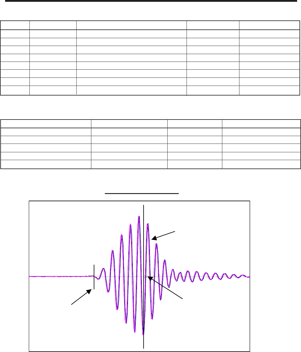
2-88
1010NFM-3JSection 2
Digitized Receive Signal
TN marker Crossover Marker
Command Line appears here
F 0.73
VS 1469.73
[ ] 1691:1929 476
D 4:4 4
Tn 55.06
dT 3.11
S 72
1
SN 124:1
CQ 17:1
Ideal Vsig Display
91
3
Trade Name Application Max Temp. Remarks
Motor Oil, Gear Oil, STP Portable, Short Term 250°F, 121°C Messy
Auto Wheel Bearing Grease Moderate to Long Term 250°F, 121°C Good Gen’l Compound
Silicone Rubber (RTV) Permanent As Rated Cure at Ambient
2-Part Epoxy Permanent As Rated Cure at Ambient
Gasket Cement Permanent 375°F, 190°C Cure at Ambient
“Alternative” COUPLING COMPOUNDS
Part# Name Application Max Temp. Remarks
CC-102 Ultragel Portable, Short Term (< 24 Hours) 110°F, 43°C Water Soluble
CC-110 RTV-734 Permanent (Plastic Xducers Only) 150°F, 65°C Avoid Humidity
CC-114 Magnalube Long Term Teflon Grease 300°F, 159°C Temp. affects life
CC-117 Dow-340 Temperature Sensors Only 400°F, 205°C Heat Sync Comp.
CC-120 Denso Submersible Applications 150°F, 65°C Good Noise Damp
CC-122 KryTox Long Term High Temperature 450°F, 232°C Use for all HT
CC-124 Barco Bond Permanent Epoxy for Metal Xdcrs 150°F, 65°C Cure at Ambient
CC-128 SuperLube Long Term Grease 375°F, 190°C Avail. In Stores
“Official” COUPLING COMPOUNDS

3-1
1010NFM-3JSection 3
3. HARDWARE INSTALLATION GUIDE
3.1 PREPARING TO MOUNT THE TRANSDUCERS
Installing the transducers is fairly straightforward. However, careful planning will avoid any snags that
may delay the installation. Previously, based on the input you fed into the meter’s computer, it had
recommended the transducers size, mounting option and spacing. With the transducers at hand, we
are now ready to mount them. But first, some very important preliminary work must be done which
consists of:
zSelecting a mounting option for your application
zSelecting a location on the pipe
zPreparing the pipe to accept the transducers
NOTE: When installing transducers, do not key in the V/M (Version/Modification) label number
as the Transducer Size.
3.1.1 HOW TO IDENTIFY 1011 TRANSDUCERS AND MOUNTING HARDWARE
1011 series of universal transducers and mounting frames have the following color-codes for easy
identification:
GOLD ....................... SIZE ‘A’ GREEN…………………SIZE ‘D’
BLUE ........................ SIZE ‘B’ BLACK…………………SIZE ‘E’
RED ......................... SIZE ‘C’
The transducer part number located on the front face provides a more detailed identification. For ex-
ample, the Part Number: 1011PPS-C2 means:
3.1.2 SELECTING A LOCATION FOR CLAMP-ON TRANSDUCERS
Locate the transducers downstream from the center of the longest available straight run. A location ten
pipe diameters or greater downstream from the nearest bend will provide the best flow profile condi-
tions.
Do not (if possible) install the transducers downstream from a throttling valve, a mixing tank, the dis-
charge of a positive displacement pump or any other equipment that could possibly aerate the liquid.
The best location will be as free as possible from flow disturbances, vibration, sources of heat, noise,
or radiated energy.
PORTABLE
MODEL
PLASTIC
STD. TEMP.
SIZE
1 0 1 1 P P S . C 2

3-2
1010NFM-3J
Section 3
zAvoid mounting the transducers on a section of pipe with any external scale. Remove all scale,
rust, loose paint, etc., from the location.
zDo not mount the transducers on a surface aberration (pipe seam, etc.)
zDo not mount transducers from different ultrasonic flowmeters on the same pipe. Also, do not run
the transducer cables in common bundles with cables from communication equipment, other Con-
trolotron systems, or any type of ultrasonic equipment. You can run these cables through a com-
mon conduit ONLY if they originate at the same flowmeter.
zNever mount transducers under water, unless you order submersible units and you install them in
accordance with factory instructions.
zNever mount transducers on the top or bottom of a horizontal pipe. The best placement on a
horizontal pipe is either the nine o’clock or three o’clock position for Reflect Mode, or one trans-
ducer at nine o’clock and one transducer at three o’clock for Direct Mode. Mounting on a vertical
pipe is recommended only if flow is in the upward direction.
When mounting on a vertical pipe flowing in a downward direction make sure there is sufficient back
pressure in the system to maintain a full pipe.
3.1.3 CLAMP-ON TRANSDUCER MOUNTING MODES
Siemens clamp-on transducers support Direct or Reflect mounting modes. The flow computer recom-
mends a mounting mode after analyzing your pipe and liquid data entries. However, you can install
clamp-on transducers in the way that best suits your application and the transducer type you pur-
chased.
REFLECT MOUNT
(Pipe shown in Top View for ease in visualizing sonic path)
Upstream
Transducer
Sonic Path
Pipe
Downstream
Transducer
END VIEW
(Horizontal Plane)
Transducer located
at 9 o'clock Transducer located at
3 o'clock
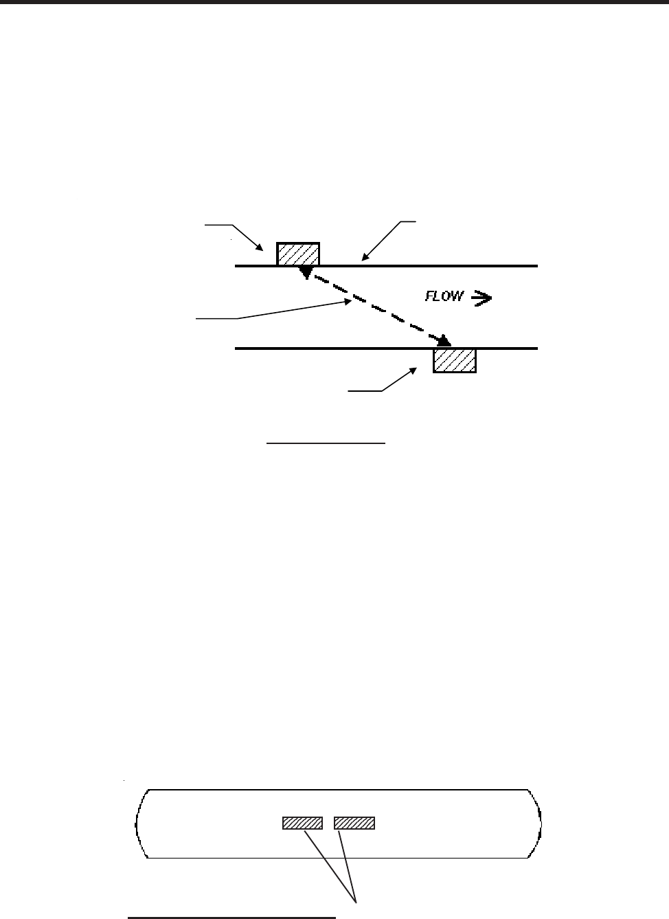
3-3
1010NFM-3JSection 3
We recommend Reflect mount whenever possible. This is the simplest way to mount the transducers.
Also, Reflect mount resists abnormal flow profile conditions such as cross-flow within the flow stream.
Reflect mode supports the AutoZero function, which zeroes the meter automatically without stopping
flow. In addition, Reflect mount may be the only possibility if conditions do not allow access to the
opposite side of the pipe.
Direct mount provides a shorter sonic beam path. This can improve performance with sonically attenu-
ative liquids or pipe materials. We recommend using Direct mount for plastic pipes. Compared to
Direct mounting, Reflect mount requires almost double the amount of a mounting length. Therefore,
Direct mount may be the only option if the availability of mounting space is limited.
DIRECT MOUNT
3.1.4 PREPARING THE PIPE
1. Pick a mounting location with the longest straight run. You must have easy access to at least one
side of your pipe. The mounting location must remain full, even at zero flow.
2. Decide on your mounting mode (Direct or Reflect). Always use Reflect Mode whenever possible.
You may only need to use Direct Mode if your pipe is plastic.
3. After receiving the spacing dimensions from the Installation Menu, prepare the pipe surface. De-
grease the surface, if necessary, and remove any grit, corrosion, rust, loose paint, etc. Use abra-
sive material provided to provide a clean contact surface for the transducers.
4. Refer to the next sections for illustrated instructions on how to locate each area to be cleaned and
how to use each mounting option.
Please note that the instructions show vertical mounting for clarity purposes only. Do not
install transducers on the top of a pipe.
Cleaned areas. Clean an area 1/2” on either side
of transducer and an additional 1/2” along the
length of the transducer.
Pipe
PREPARING THE PIPE SURFACE
(Pipe shown in Top View for ease in visualizing sonic path)
Upstream
Transducer
Sonic Pat
h
Pipe
Downstream
Transducer
Upstream
Transducer
Sonic Path
Pipe
Downstream
Transducer
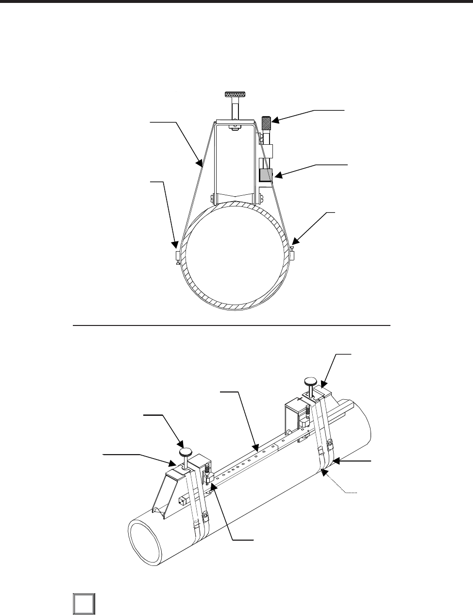
3-4
1010NFM-3J
Section 3
3.1.5 REFLECT MODE - MOUNTING FRAMES AND SPACER BAR
The combination of a spacer bar with mounting frames is the easiest way to mount in Reflect Mode.
The result is a rigid structure that eliminates spacing measurements, and maintains the transducer-to-
transducer geometry. In addition, reflect mounting allows you to move the entire assembly while main-
taining the original transducer spacing.
1. Perform all required menu steps until the flow computer issues the number index and prompts
you to press to finish the transducer install routine. Stop at this point.
Note the number index value displayed in the Pick/Install menu. You will use this number to properly
space the transducers. Check to ensure that you have a matched set of transducers. They both should
have the same S/N number but marked with either an “A” or “B” (e.g., 100A and 100B).
ENT
INSTALLATION - REFLECT MOUNT WITH FRAMES AND SPACER BAR
NOTE: Minimum Ltn 0.75 in. (18 mm)
Mounting Strap
positioned around
Mounting Frame
Mounting Strap
Adjusting Screw
Optional on larger pipes,
you can link straps together
to surround pipe Spacer Bar
(Front view)
Spacer Bar Platform &
Clamping Screw
Mounting Strap
positioned around
Mounting Frame
Optional on larger pipes,
you can link straps together
to surround pipe.
Space Bar Platform &
Clamping Screw
Space Bar
(Front View)
Mounting Strap
Adjusting screw
Mounting Strap
Transducer Clamping
Screw
N
ote optional 2nd
Mounting Strap
shown.
L
arger pipes may
need an additional
strap for a more
secure mount
Spacer Bar
Spring Clip
(Not present on some
models)
1012 Series
Mounting Frame
Spacer Bar
Platform and
clamping screw
Spring Clip
(Not present on
some
models)
Transducer Clamping
Screw
Spacer Bar
Spacer Bar
Platform and
clamping screw
Mounting Strap
Note operational
2nd Mounting Strap
shown.
Larger pipes may
need an additional
strap for a more
secure mount.
1012 Series
Mounting Frame

3-5
1010NFM-3JSection 3
2. On a flat surface, attach the spacer bar to a mounting frame so that the reference hole on the
spacer bar fits over the post on the platform of the frame; tighten the securing screw. Slide the
second mounting frame onto the other end of the spacer bar, align the number index hole with the
post on the platform; then tighten the securing screw. Ensure that the angled sides of both frames
face away from each other. At the mounting location, place the mounting frame/spacer bar assem-
bly on the pipe so that it rests on the top of the pipe. Wrap a mounting strap around the pipe.
Engage the end of the mounting strap with the mounting strap adjusting screw. Slide it under the
spring clip (if so equipped) of one of the mounting frames. Make sure to position it for easy access
to the mounting strap adjusting screw. Do the same to the other mounting frame.
3. Tighten the mounting strap screw enough to take up all of the slack, but not enough to prevent
rotation of the assembly. Rotate the assembly on the pipe to the 9 o’clock position ensuring that it
is a smooth area without any raised spots or seams. Mark a generous area around the mounting
frames (1/2” on either side and half again the length front and back) with a pencil or chalk. Move or
revolve the assembly away from the area marked (loosen straps if necessary to do this).
4. Prepare the two areas you marked by de-greasing the surface, if needed, and removing any grit,
corrosion, rust, loose paint or surface irregularities with the abrasive pipe conditioning material
provided. Clean the pipe of all debris and abrasive particles.
5. Reposition the assembly over the center of the prepared surfaces. Tighten the mounting straps to
seat the assembly firmly on the pipe. Do not overtighten.
Apply a continuous 1/8-inch bead of coupling compound to the center of the face of a transducer,
then slide it into the mounting frame but holding it away from making contact with the pipe until it
butts up against the stop (to keep from smearing couplant where it’s not needed); then push down
onto the pipe. Tighten the transducer clamping screw to hold the transducer firmly in place. Repeat
for the other transducer.
6. Observing the upstream to downstream orientation, attach the UP and DN cables to the transduc-
ers. Attach the other ends to the flowmeter’s UP and DN terminals. See Engineering Drawing
1010N-7, Single Channel or 1010DN-7 Dual-Channel.
7. You can now press the <ENT> key to finish the transducer install routine. The available Mounting
Strap kits are listed below. Each kit comes with up to two band sizes to cover its designated pipe
diameter range and a spacing guide for Direct Mount.
3.1.6 REFLECT MODE WITH SPACER BAR ONLY
The spacer bar eliminates manual spacing measurements and provides rigidity for mounting the trans-
ducers while maintaining axial alignment.
Strap Mounting Kit P/N Pipe Diameter Band Sizes (Qty.)
1012MS-1A 2" (50.8mm) to 7" #88 (2) #128 (2)
(177.8mm)
1012MS-1 2" (50.8mm) to 13" #88 (2) #152 (2)
(330.2mm)
1012MS-2 13" (330.2mm) to 24" #188 (2) #280 (2)
(609.6mm)
1012MS-3 24" (609.6mm) to 48" #152 (2)
(1219.2mm)
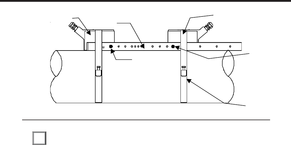
3-6
1010NFM-3J
Section 3
1. Perform all required menu steps until the flow computer issues the number index and prompts you
to press to finish the transducer install routine. Stop at this point.
Note the number index value displayed in the Pick/Install menu. You will use this index to properly
space the transducers. Check to ensure that you have a matched set of transducers. They both
should have the same S/N number but marked with either an “A” or “B” (e.g., 100A and 100B).
2. Assemble the transducers to the spacer bar, with the cable connectors facing away from each
other as shown above. The spacer bar is attached to a transducer using a transducer index screw.
One transducer is attached using the “REF” hole on the spacer bar. The second transducer is
attached to the spacer at the index hole specified in Step 1.
3. Temporarily position the assembly (in the 9 o’clock position) at the location where you
have determined it would be mounted. Ensure that it is a smooth area without any raised spots or
seams. Mark a generous area around the transducers (1/2” on either side and half again the length
front and back) with a pencil or chalk. Remove the assembly.
4. Prepare the two areas you marked by de-greasing the surface, if needed, and removing any grit,
corrosion, rust, loose paint or surface irregularities with the abrasive pipe conditioning material
provided. Clean the pipe of all debris and abrasive particles.
5. Remove transducer from the spacer bar that was attached through the REF hole. Put a mounting
strap around the pipe and engage an end into the adjusting screw (adjusting screw should be
pointing up). Apply a 1/8-inch continuous bead of couplant compound down the center (the long
way) of the contact surface of one of the transducers (see Recommended Sonic Coupling Com-
pounds Section 5, page 5-9). Place the transducer on the pipe center in the middle of one of the
areas you have cleaned with its cable connector pointing away from the other cleaned area. Holding
the transducer in place, slide the mounting strap over it (and under the clip if there is one) and tighten
with a screwdriver. While tightening, check to ensure that the white dot under the front label is
centered on the pipe and that there is equal space on both edges. Also, make sure to position strap
for easy access to the mounting strap adjusting screw.
6. Repeat Step 5 with the second transducer leaving it still attached to the spacer bar. Apply a 1/8-inch
bead of couplant to the transducer. At the same time you place it in the middle of the second area
prepared, secure the spacing bar to the already mounted transducer by inserting the transducer
index screw through the REF hole on the Bar. Put mounting strap around transducer and tighten as
ENT
1011 Series
Transduce
r
Spacer Bar
Spring Clip
Spacer Bar Reference
Index Securin
g
Scre
w
INSTALLATION - REFLECT MOUNT WITH TRANSDUCERS AND SPACING BAR
Mounting
Stra
p
Spacer Bar
N
umber Index
Securing Screw
1011 Series
Transducer Spacer Bar Spring Clip
Spacer Bar
Number Index
Securing Screw
Mounting
Strap
Spacer Bar
Reference
Index Securing
Screw
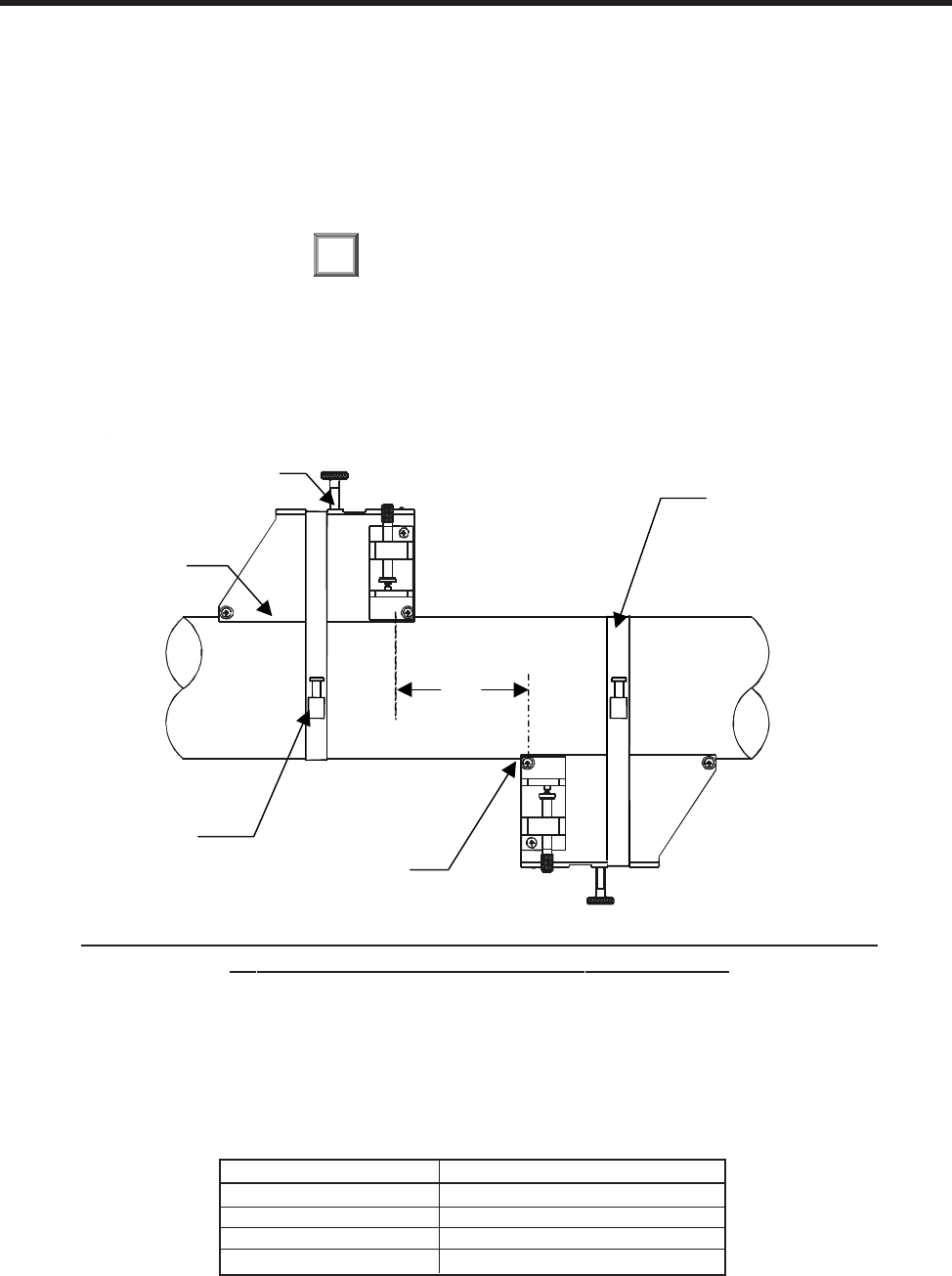
3-7
1010NFM-3JSection 3
in Step 5. Sight along spacer bar to ensure axial alignment to the pipe. Adjust if necessary and do not
overtighten. Ensure that the transducers do not move while tightening.
7.Connect the transducer cable, ensuring that you have observed the upstream/downstream orienta-
tion in respect to the cable and the input jack on the flow computer. If this is a dual-channel unit, make
sure you are connecting the cables to the correct channel’s input jacks. Repeat this procedure for
the number index transducer.
8.Return to the menu, and press to finish the transducer install routine.
3.1.7 DIRECT MODE - MOUNTING FRAMES, SPACER BAR AND SPACING GUIDES
The combination of mounting frames, spacer bar and spacing guides is the recommended way to
mount Direct Mode transducers. The mounting frame establishes the axial alignment of the transduc-
ers, and allows you to remove and replace either transducer while preserving their exact mounting
location.
For Direct Mode mounting, you will use a spacer bar to establish the distance between transducers
and a spacing guide to easily locate the transducers at the nine o’clock and three o’clock positions.
Should the distance between transducers be beyond the span of a spacer bar, a measuring tape can
be used. The Mylar spacing guide comes in various lengths and widths to accommodate most pipe
sizes (see list below).
ENT
Spacing Guide P/N Size
1012-145-1A 2" x 26" (50.8 x 660.4 mm)
1012-145-1 2" x 45" (50.8 x 1143.0 mm)
1012-145-2 4" x 81" (101.6 x 2057.4 mm)
1012-145-3 4" x 155" (101.6 x 3937.0 mm)
INSTALLATION - DIRECT MODE WITH TRANSDUCERS, MOUNTING FRAMES
SPACER BAR (Not Shown) AND SPACING GUIDE
Ltn
Transducer
Clamping
Scre
w
Mounting
Frame
Mounting
Strap
Ltn
Reference
N
otc
h
Mounting Strap
Adjusting Screw
Transducer
Clamping
Screw
Mounting
Frame
Mounting Strap
Adjusting Screw Ltn
Reference
Notch
Mounting
Strap
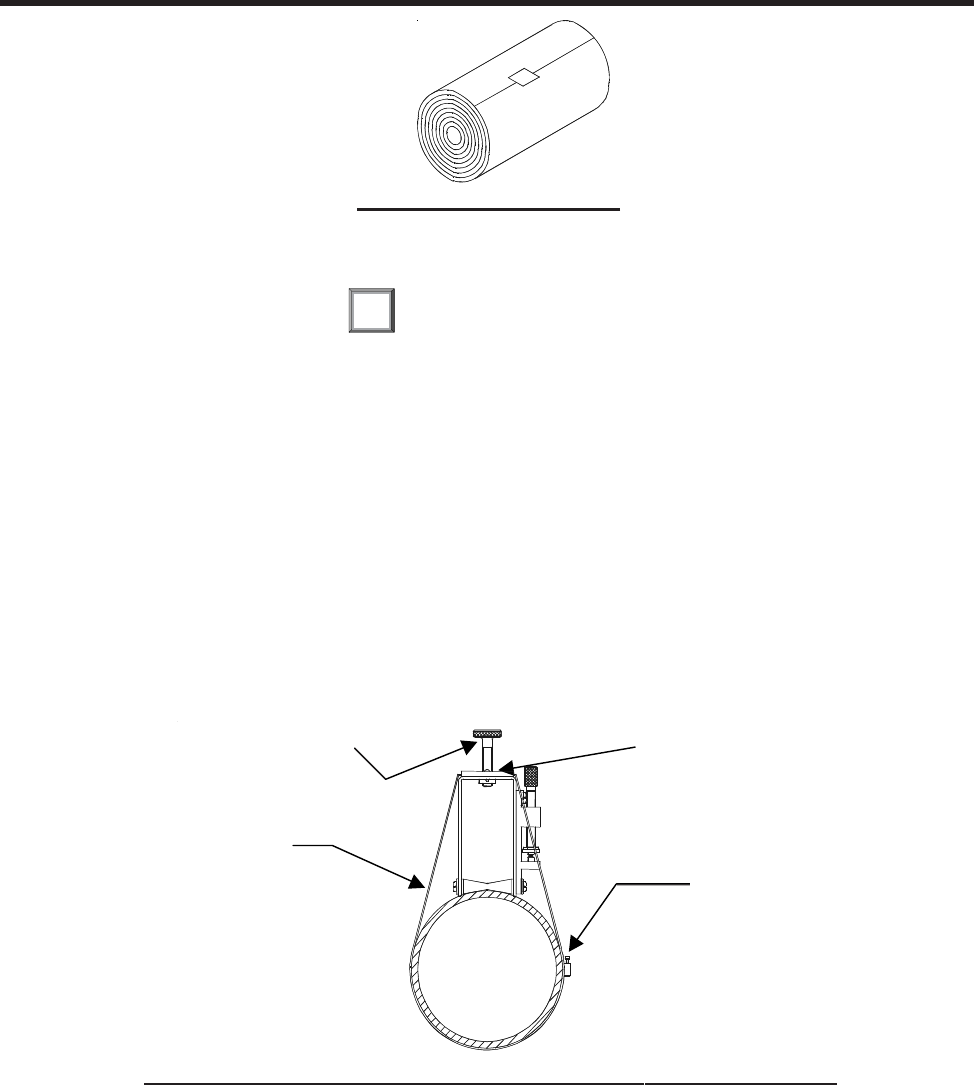
3-8
1010NFM-3J
Section 3
1. Perform all the required menu steps up until the point where the flow computer issues the number
index and prompts you to press to finish the transducer install routine.
Make a note of the number index displayed in the Pick/Install menu. Check to ensure that you have
a matched set of transducers. They both should have the same S/N number but marked with either
an “A” or “B” (e.g., 100A and 100B).
2. Temporarily position one of the frames on the pipe where you will be mounting it. Ensure that this is
a smooth area without any raised areas (seams, etc.) With a pencil or chalk, mark a generous area
around the frame (1/2” on either side and half again the length front and back). Remove the assem-
bly.
3. Prepare the area you marked by de-greasing surface, if needed, and removing any grit, corrosion,
rust, loose paint or surface irregularities with the abrasive material provided.
4. Put a mounting strap around the pipe and engage an end into adjusting screw (screw should be
pointing up). Position frame in the middle of area you have cleaned and centered on the pipe with its
angled end facing away from where the other frame will sit.
5. Slide the mounting strap over it (and under the clip if there is one) and tighten with a screwdriver.
While tightening, check to ensure that the center of the tapered roller is centered on the pipe.
6. Attach the second frame to the spacer bar with an index spacer screw into the index hole specified
in Step 1. The angle on the frame should be facing away from the direction the length of the bar is
going. Now attach the free end of the spacer bar by inserting an index spacer screw through the
REF hole on the spacer bar and then into the hole on the mounted frame. Tighten. Sight to ensure
that this frame is lined up in center of pipe and while holding alignment, place a dot (with pencil or
ENT
MYLAR SPACING GUIDE
WRAPPING STRAP UNDER PIPE AND ATTACHING TO ADJUSTING SCREW
Mounting Strap
Adjusting Screw
Transducer Clamping
Screw
Mounting Strap
Spring Clip
Transducer Clamping
Screw
Mounting Strap
Spring Clip
Mounting Strap
Adjusting Screw
Mounting Strap
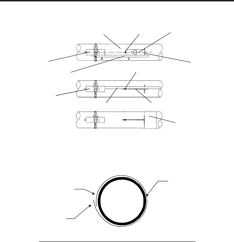
3-9
1010NFM-3JSection 3
chalk) in the center of the tapered roller at the bottom of the frame (see “A” below). While holding,
also mark along the front edge of the frame with pencil or fine chalk line (see B below).
7. Disassemble the spacer bar and the unmounted frame. Use the bar as a straight edge and, with
one edge against the mounted frames tapered roller center and the other crossing the dot you
drew, draw a line crossing the dot (see “B” above). Set the bar aside.
8. Wrap the mylar spacing guide around the pipe so that the left edge is against the transducer edge
mark (see “C” above). Arrange so that one end overlaps the other by at least three inches. Trim to
fit if necessary, but be sure not to trim at the overlapping end in order to keep it square.
9. Realign left edge of the guide with the transducer edge mark. Line up both vertical edges of the
guide and ensuring that it is snug around the pipe, mark along the overlapping edge.
10. Remove Mylar spacing guide and lay it out on a flat surface. Either measure the exact distance
halfway between the overlap edge and the mark at the overlap, or fold the guide from the overlap
edge to overlap mark and draw a line at the fold or halfway point (see next page).
Transducer
Pi
p
e
Spacer Bar
Myla
r
Spacing
Guide
Transducer
Spacer Bar
Dot
Dot
Line
A
B
C
Transducer
Spacer Bar
Spacer Bar
Dot
Line
Transducer
Mylar
Spacing
Guide
Transducer
Edge Line
Transducer
Dot
Pipe
WRAPPING THE MYLAR SPACING GUIDE AROUND THE PIPE
E
ND VIEW
3" Overlapping
Edge
Mylar
Spacing Guide
Trim material from
inner edge if
necessary
Trim material from
inner edge if
necessary
3” Overlapping
Edge
Mylar
Spacing Guide
End View
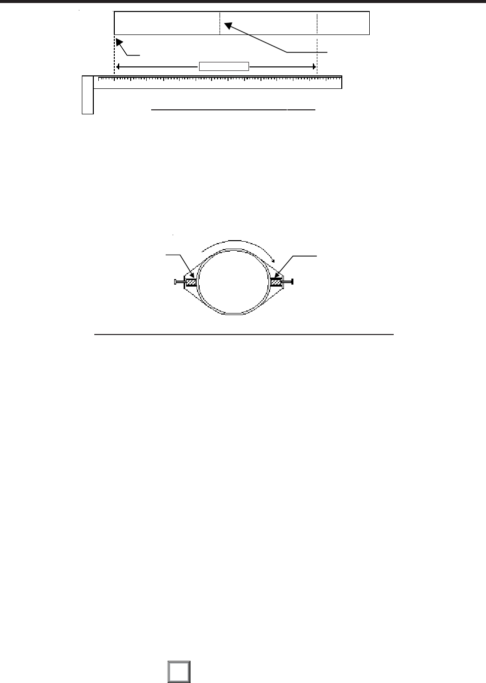
3-10
1010NFM-3J
Section 3
ENT
11. Reinstall the spacing guide; its left edge abutting the transducers edge mark on the pipe and the
overlapping edge in line with the dot (now a line) on the pipe (see “C” on previous page). Tape it in
this position on the pipe. Take the second frame and place it against the edge of the guide with its
tapered roller centered on the center mark on the guide. Temporarily position the frame (in the 3
o’clock position opposite the mounted frame - see below) where it will be mounted. Ensure that
this is a smooth area without any raised spots (seams, etc.). Mark a generous area around the
mounting frames (1/2-inch on either side and half again the length front and back) with a pencil or
chalk. Remove the frame and the mylar guide.
12. Prepare the area you marked by de-greasing the surface, if needed, and removing any grit, corro-
sion, rust, loose paint or surface irregularities with the abrasive pipe conditioning material provided.
Clean the pipe of any debris and abrasive particles.
13. Replace the mylar guide back in the same position it was in and retape it to the pipe.
14. Put a mounting strap around the pipe and engage an end into adjusting screw (screw should be
pointing up). Position frame in the middle of area you have cleaned and centered on the pipe with its
angled end facing away from where the other frame will sit; and aligned with the edge and center
marks on the guide. Slide the mounting strap over it (and under the clip if there is one) and tighten
with a screwdriver. While tightening, check to ensure that the center of the tapered roller is cen-
tered on the pipe.
15. Apply a 1/8-inch continuous bead of couplant compound down the center (the long way) of the
contact surface of one of the transducers. Place the transducer into one of the frames so that the
couplant compound does not smear until it contacts the pipe. Slide it in until it butts against the stop
and, while holding in-place, tighten the transducer clamping screw tight enough to hold firmly in-
place. Do the same with the other transducer.
16. Connect the transducer cable, ensuring that you have observed the upstream/downstream orien-
tation in respect to the cable and the input jack on the flow computer. If this is a dual-channel unit,
make sure you are connecting the cables to the correct channel’s input jacks. Repeat this proce-
dure for the number index transducer.
17. Return to the menu, and press to finish the transducer install routine.
FINDING THE HALFWAY DISTANCE
Overlap Edge Mark (or fold) exactly
at half-way point
SPACING GUIDE
CIRCUMFERENCE
ALIGNING THE TRANSDUCERS FOR DIRECT MODE OPERATION
3 o’clock
Transducer
9 o’clock
Transducer
9 o’clock
Transducer 3 o’clock
Transducer
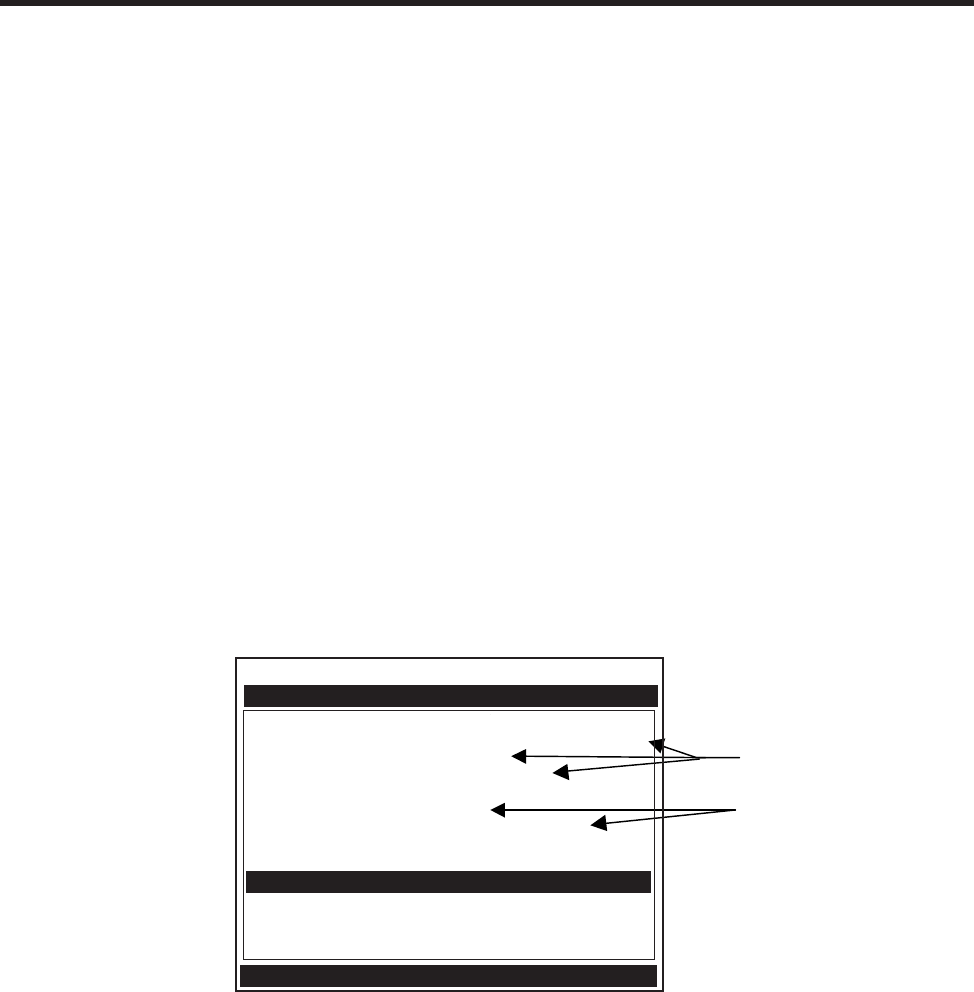
3-11
1010NFM-3JSection 3
3.1.8 USING 1012T MOUNTING TRACKS
The 1012TP and 1012THP Mounting Tracks provide a rigid mounting platform for Series
1011 universal or high precision size A or B transducers. The mounting tracks service pipe sizes up to
a maximum of 5.00” (140 mm) outer diameter. Operating temperatures are supported up to 250°F
(121°C). The assembly consists of lightweight aluminum track rails with integral transducer clamping
screws. Attached index pins enable positive locating of the transducers at fixed spacing locations.
Roller-chains and tension screws secure the assembly to the pipe. The following instructions refer to
1011 universal transducers. Please refer to Engineering Drawing 1012TP-7 for reflect mounting of high
precision transducers and 1012THP-7 for direct mounting of high precision transducers.
The 1012T mounting tracks support both Direct and Reflect mounting modes. The flow computer
recommends the appropriate transducers, mounting track and mounting mode, based on the pipe
data entries. Refer to the instructions in paragraph 2.4 for details on the Transducer Installation proce-
dure. If necessary, review paragraphs 3.1.2 through 3.1.4 for details on how to select and prepare a
mounting location on your pipe.
Installing a 1012T Mounting Track in Reflect Mode
Paragraph 2.4 describes the Transducer Installation procedures that lead up to the automatic selection
of transducers, mounting mode and spacing method. Examine the figure below, which shows a typical
Pick/Install Xdcr menu screen. Note the automatic assignment of model numbers for the transducer
and mounting track, plus the designation of the number index.
This example requires a Model 1012T Mounting Track to accommodate size B3 universal transduc-
ers. Note the reported number index. You will be inserting an index pin into this hole on the track rail to
position one of the transducers (see diagram on next page).
1. Perform all required menu steps up until the point where you respond to the [Install Completed?]
prompt. Note the reported number index. You will be inserting index pins into this hole and the
reference hole on the track rail (see diagram on next page). Check to ensure that you have a
matched set of transducers. They both should have the same S/N number but marked with either
an “A” or “B” (e.g., 100A and 100B).
Note selection of
type, size and
mounting mode.
Note selection of
mounting track part
number and number
index.
Siemens 2 Channel [1] SITE1
Key [Install] after mounting transducers
Pick/Install Xdcr
Transducer Model 1011 Universal
Transducer Size B3
Xdcr Mount Mode Reflect
Spacing Offset Minimum
Number Index 6
Spacing Method Track 1012TP
Ltn Value (in) 0.581
Install Completed? No
Empty Pipe Set Channel Not Setup
Zero Flow Adjust Channel Not Setup
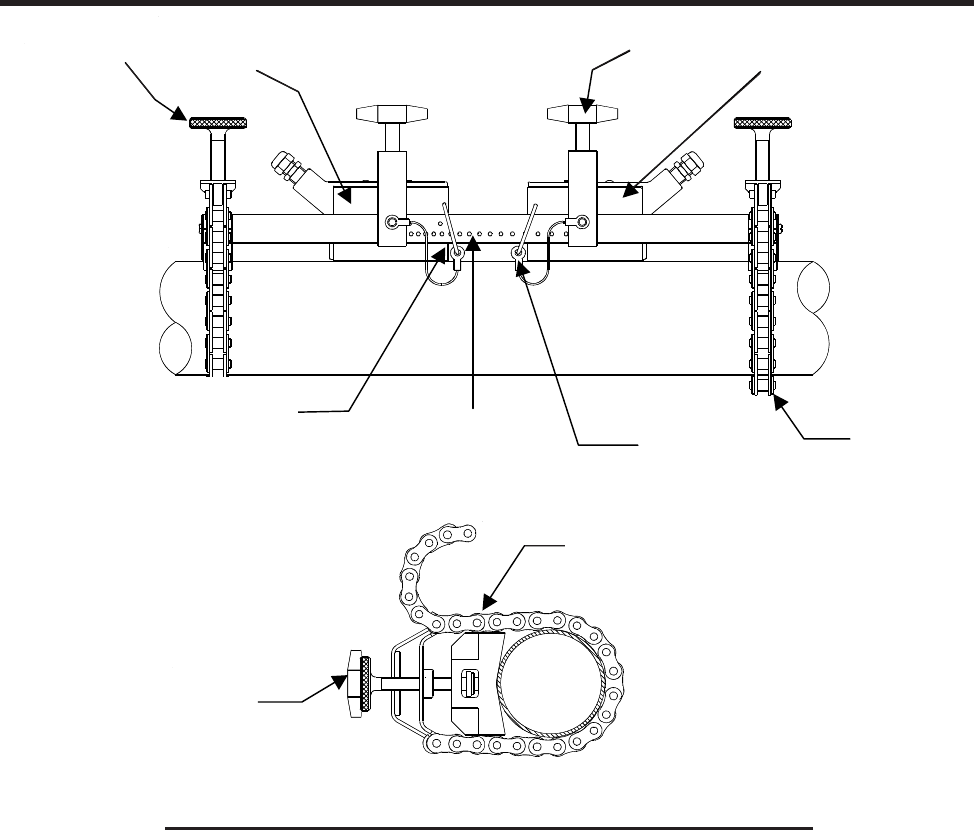
3-12
1010NFM-3J
Section 3
2. Place the track rail assembly on the top surface of the pipe at the location where you have deter-
mined it would be mounted. Ensure that it is a smooth area without any raised spots or seams.
Holding the assembly in place, loop one of the roller chains under the pipe, pull it around and main-
tain tension while slipping a link over the tension screw hook. Tighten the tension screw enough to
hold the assembly on the pipe, but still allow rotation. Repeat for the other roller chain. Rotate the
track rail assembly to the intended nine o’clock mounting position on the pipe, then tighten both
tension screws just enough to prevent rotation. Do not overtighten.
3. Mark a generous area around the transducers (1/2-inch on either side and half again the length front
and back) with a pencil or chalk. Loosen and move the assembly away from marked area. Prepare
the two areas you marked by de-greasing the surface, if needed, and removing any grit, corrosion,
rust, loose paint or surface irregularities with the abrasive pipe conditioning material provided. Clean
the pipe of all debris and abrasive particles.
4. Insert the index pin into the reference hole. Select a transducer, apply a thin band of couplant com-
pound to the transducer’s contact surface. Place the transducer between the track rails, slightly
behind the pin and under the clamping screw assembly. Slide it forward until it butts up firmly against
the reference pin.
FlowÎ
Reference Pin
Shown Inserted
Chain Tension
Screw
Upstream
Transducer
Transducer
Clamping Screw Downstream Xdcr
Roller
Chain
N
umber Index pi
n
Shown inserted
Track Rail
Assembly
Chain Tension
Screw Upstream
Transducer
Transducer
Clamping Screw Downstream
Transducer
Roller
Chain
Number Index Pin
Shown Inserted
Track Rail
Assembly
Reference Pin
Shown Inserted
Flow Î
INSTALLATION - REFLECT MOUNT WITH MOUNTING TRACK
FRONT VIEW Ç
Chain
Tension
Screw
Loop Chain over
tension screw hook
Chain Tension
Screw
Loop Chain
over tension
screw hook
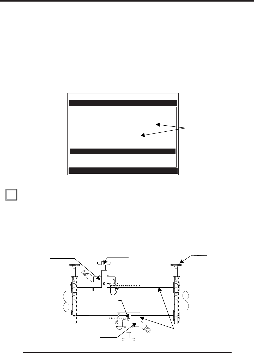
3-13
1010NFM-3JSection 3
5. Once transducer is in place, secure with the transducer clamping screw. Do not overtighten. Ob-
serve the upstream/downstream orientation and connect the transducer cable to the computer’s
input jack. If a dual-channel unit, make sure you connect the cable to the input jacks of the correct
channel. Repeat this procedure for the number index transducer.
Installing a 1012T Mounting Track in Direct Mode
Paragraph 2.4 describes the Transducer Installation procedures that lead up to the automatic selection
of transducers, mounting mode and spacing method. Shown is a Model 1012T mounting track to
accommodate size B3 universal transducers. Examine the figure below which shows a typical Pick/
Install Xdcr menu screen. Note the automatic assignment of model numbers for the transducer and
mounting track, plus the designation of number index.
1. Perform all required menu steps up until the point where the flow computer prompts you to press
to finish the transducer install routine. Note the reported number index.
You will be inserting an index pin into this hole and the reference hole. Check to ensure that you have a
matched set of transducers. They both should have the same S/N number but marked with either an
“A” or “B” (e.g., 100A and 100B).
2. The direct mount configuration uses two track rails, one for each transducer, installed 1800 apart on
the pipe. One track rail includes the tension screw while the other has a locating stud to support the
chain (see below and on next page).
ENT
Transducer Model 1011 Universal
Transducer Size B3
Xdcr Mount Mode Direct
Spacing Offset Minimum
Number Index 4
Spacing Method Track 1012TP
Ltn Value (in) 0.217
Install Completed? No
Empty Pipe Set Channel Not Setup
Zero Flow Adjust Channel Not Setup
Siemens 2 Channel [1] SITE1
Key [Install] after mounting transducers
Pick/Install Xdcr
Note selection of track
P/N, Mount Mode and
Number Index.
INSTALLATION – DIRECT MOUNT 180º OPPOSED WITH MOUNTING TRACK
Upstream
Transducer
Chain
Tensioning
Screw
Transducer Clamping
Screw
Downstream
Transducer
Number
Index Pi
n
TOP VIEWÇ
Track Rails
Upstream
Transducer
Transducer Clamping
Screw
Chain Tensioning
Screw
Track Rails
Downstream
Transducer
Number
Index Pin
TOP VIEW ÏÏ
ÏÏ
Ï

3-14
1010NFM-3J
Section 3
Tension Screw
Hook
Center of this link is over the
locating stud. An equal number of
links on either side of this stud
ensures 180° opposed installation.
Chain
Tension
Screw
Xdcr
Clamping
Screw
3. If this is a horizontal pipe, place the track with the chain tension screws on top of the pipe (screws
up, the chains hanging down and the numbered scale facing you) where you have determined it
would be best to mount it.
4. Place the other track (with the centering stud on the bottom and the lettering on the scale toward
the same side as the top track) directly underneath it (1800). Hold in place while you wrap the chain
around the pipe; first onto the centering stud on the bottom track and then onto the hook under the
Tensioning Screw. With the chain in-place, count the number of links between the beginning of the
chain and the centering stud; and then between the centering stud and the hook. They both should
have the same number of links. Arrange so they do and then loosely tighten. Do the same with the
other chain. For a vertical pipe installation, it will probably be much easier to tie, tape or bungee
cord the two tracks in place while chaining.
5. Wrap a length of the mylar spacing guide around the pipe and against the end of the track assem-
bly. Ensure that the edges on both sides align and tape to the pipe. Loosen the chains enough to
allow you to rotate the track assembly 900 until one track is in a 9 o’clock position and the other in
a 3 o’clock position on the pipe (horizontal pipe). Tighten both chains but not too tight.
6. Insert an index pin into the REF hole of the track with the tensioning screws. Take one of the
transducers and insert it between the track rails and to the left of the index pin with the cable
connector pointing away from the pin. Move the transducer right until the pin stops it. Hold it in this
position and move the transducer clamping screw over the transducer and tighten. Insert the other
index pin into the index hole (see Step 1) on the other track marked “Direct Mode Spacing.” Insert
the second transducer (with its cable connector pointing away from the pin) between the track rails
on the right side of the pin and move the transducer left until it’s stopped by the pin and then follow
the same procedure as with the first transducer.
7. Mark a generous area around the transducers where they contact the pipe with a pencil or chalk.
Make a mark showing the center between the tracks on the mylar guide. Release the tension on
the transducers and remove them. Loosen the chains and rotate the track assembly on the pipe so
you can gain access to the areas marked.
8. Prepare the area you marked by degreasing the surface, if needed, and removing any grit, corro-
sion, rust, loose paint or surface irregularities with the abrasive pipe conditioning material provided.
9. Revolve the tracks on the pipe into the position they were originally in by using the edge of the mylar
guide as a stop for both the upper and lower tracks and the mark on the guide to center that track.
This time, before installing each transducer, apply a 1/8-inch continuous bead of couplant com-
pound along the center (the long way) of the contact surface of the transducer. Also, keep the
transducers lifted slightly from the pipe when installing until the transducer is against the pin; then
push down against the pipe. Remember to install the transducers with the cable connectors facing
away from each other.
Once the transducer is in place, Secure it with its clamping screw. Do not overtighten.
NOTE: Some transducers require a right-angle adapter. This adapter should be installed be-
fore placing the transducer in the tracks.
Chain Tension
Screw
Tension Screw
Hook Center of this link is over the
locating stud. an equal number of
links on either side of this stud
ensures 180 degrees opposed
installation.
Transducer
Clamping Screw
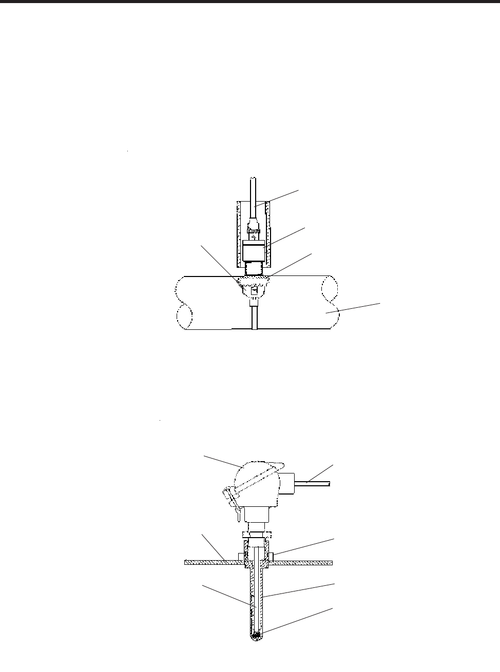
3-15
1010NFM-3JSection 3
THERMAL COUPLANT
991T CLAMP-ON TEMPERATURE
SENSOR (MATCHED PAIR REQUIRED)
CUSTOMER’S PIPE
1012EC SERIES CABLE
992EMTN MOUNTING
ASSEMBLY
3.2 MOUNTING TEMPERATURE SENSORS
In order to accurately measure temperature differential in energy flow loops, Siemens Energy Flowme-
ters are designed to work with a pair of matched temperature sensors. These are available in clamp-
on style 991T, or in insert (thermowell) style 991TW. Both styles incorporate 1000 ohm platinum RTD’s
for high precision.
10. Connect the transducer cable, ensuring that you have observed the Upstream/Downstream orien-
tation in respect to the cable and the input jack on the flow computer. If this is a dual-channel unit,
make sure you are connecting the cables to the correct channel input jacks.
1012EC SERIES
CABLE
THREADED PIPE
FITTING
THERMOWELL
THERMAL
COUPLANT
PIPE WALL
991TW TEMPERATURE
SENSOR CONNECTOR HEAD
ASSEMBLY
SPRING LOADED
SENSING ELEMENT
Clamp-on style sensors are mounted on the surface of the monitored pipe using 992EMT series mount-
ing assemblies. Apply a generous quantity of the thermal couplant provided to the tip of the sensor and
attach it securely to the cleaned pipe surface with the propermounting assembly. Temperature mea-
surement anomalies resulting from variations in the ambient conditions can be minimized by insulating
the pipe and sensor after installation.
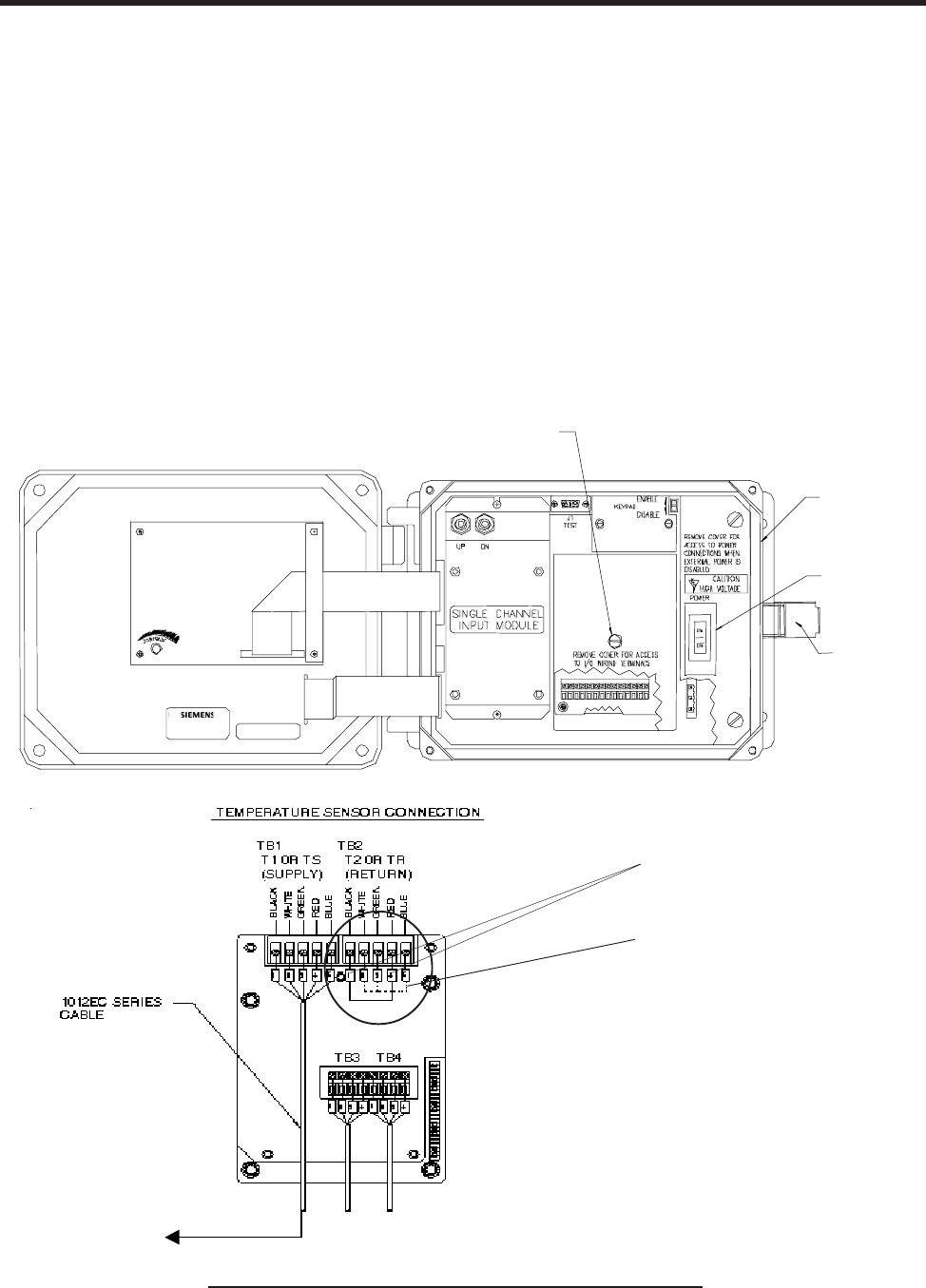
3-16
1010NFM-3J
Section 3
The 991TW insert sensors are designed to be used in pipes equipped with Thermowells. These are
spring-loaded, 1/4” diameter sensors with 1/2” NPT integral connection heads, available in several
lengths to accommodate a range of pipe sizes. Thermowells for new installations are available from
Alloy Engineering Company in Bridgeport, Connecticut.
3.2.1 WIRING TEMPERATURE SENSOR TO THE ANALOG INPUT MODULE
WARNING: Set flowmeter and instrumentation power to OFF when inserting or removing the
Analog Input Module, or when making connections to TB1, TB2, TB3, and TB4.
zOpen the 1010 NEMA flowmeter top cover by releasing the cover latch.
zPlace the power switch to the OFF position.
zLoosen the captive thumbscrew securing the Access Cover and remove Access Cover.
zUsing a flat-blade screwdriver, remove four captive screws securing the I/O board.
zCarefully remove the I/O board and set it aside.
1010N Single Channel Temperature Sensor Inputs
TOP VIEW
SHORT TERMINALS 1 AND 4
SINCE T2 IS NOT BEING USED
- see note below.
TO SENSOR
NOTE: If this meter is using only one RTD
temperature sensor, short terminals
1 and 4 of TB2 with a jumper wire to
complete the dual RTD current loop.
Refer to paragraph 3.2.1 step 3
on next page.
Access Cover
Screw
1010N
Power Switich
Latch

3-17
1010NFM-3JSection 3
zTighten all TB1 and TB2 terminal block screws.
zReplace I/O Board and secure with four captive screws.
zReplace Access Cover and finger tighten captive thumbscrew.
zUsing a flat-blade screwdriver, loosen Terminal Block TB1 and TB2 screws.
zConnect the wires of the 1012EC Series cable as follows:
3.2.2 1010N SUPPLY AND RETURN CONNECTIONS
Terminals for the supply and return sensor connections are located on the Analog Input Module as
previously shown. For other terminal locations on System 1010N Single Channel and Dual Channel
units, see drawings 1010N-5-7 or 1010N-5D-7, respectively. For terminal locations on Multi-Channel
units, see drawing 1010N-8M-7.
WARNING: Set flowmeter and instrumentation power to OFF when inserting or removing the
module, or when making connections to TB1, TB2, TB3, and TB4.
1. Connect the RTD liquid temperature cable (1012EC) as shown in the table below:
1012EC SERIES
CABLE TERMINAL TB1
WIRE #1 (Black) to TB1-1
WIRE #2 (White) to TB1-2
WIRE #3 (Green to TB1-3
WIRE #4 (Red) to TB1-4
WIRE #5 GND/SHLD (Blue) to TB1-5
2. Complete the temperature sensor current loop by shorting together terminals 1 and 4 of the
unused TB2 temperature sensor terminal block.
3. Ground the voltage sensing leads (terminals 2 and 3 of TB2) by connecting them both to
terminal 5.
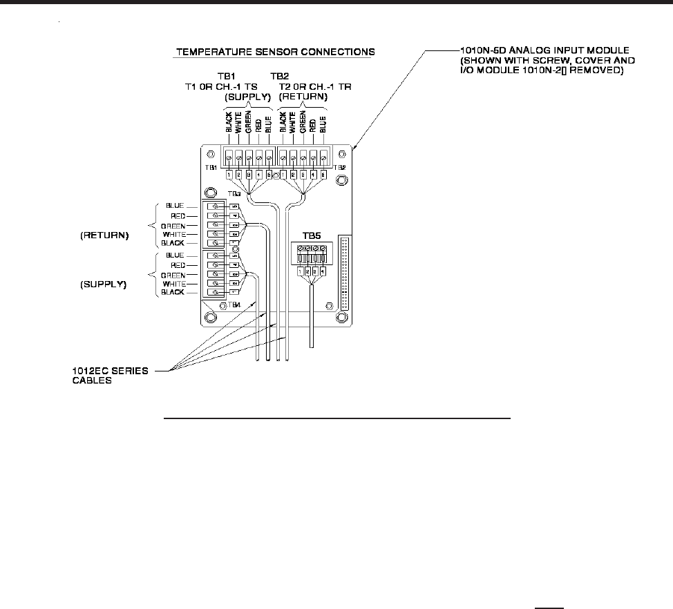
3-18
1010NFM-3J
Section 3
1010N Dual Channel Temperature Sensor Inputs
3.2.3 NOTES ON SYSTEM 1010 ANALOG INPUT MODULES
Single Channel Models
zSystem 1010 NEMA flowmeters report input module temperature sensor connections T1 and
T2 as system variables.
Dual Path Models
zDual Channel flowmeters report both T1 and T2 as generic variables for both channels.
zThe Dual Channel unit uses T1 for liquid temperature for Channel 1 and T2 as liquid tempera-
ture for Channel 2.
zThe Dual Path instrument uses T1 to report liquid temperature. (Note that T2 is used to report
ambient temperature in some Leak Detector systems.)
zThe Analog Input of temperature takes priority over the built-in RTD (Resistive Thermal Device)
measurement of temperature.
zIf you want both channels of a Dual-Channel meter to sense a single RTD, short TB1/2 to TB2/
2 and TB1/3 to TB2/3. This allows the same voltage to be fed to both channels. Once that is
complete, you must close the RTD current loop by connecting TB1/4+5 to TB2/4+5. (Note:
TB5 is just the cable shield.)

3-19
1010NFM-3JSection 3
3.2.4 CLAMP-ON RESISTIVE TEMPERATURE DEVICE (RTD) INSTALLATION NOTES
The Clamp-On RTD sensor, with which your 1010N is supplied, is extremely sensitive and precise. Its
contribution to the performance of your meter can be as important as that of the liquid flow sensors.
Please consult the installation drawings for details on physical installation and wiring of the RTD. In
order to produce the best possible tracking of the true liquid temperature, try to make your installation
conform to the notes on the installation drawing and these following tips:
zPrepare the pipe surface by removing paint to expose bare metal and by smoothing out any re-
maining rough spots.
zUse the thermal couplant compound (CC#117) between the face of the RTD element and the pipe
surface to improve the conductivity of the metal-to-metal contact.
zKeep the RTD out of direct sunlight or other non-pipe sources of heat or cold that may affect their
temperature sensing. The foam insulator supplied helps in this regard, but consider using addi-
tional pipe insulation for all installations exposed to extreme ambient conditions. Consider mount-
ing the RTD under the pipe in order to keep it out of direct sunlight.
zIn installations where RTD elements are exposed to harsh conditions such as condensation, salt
spray, etc., use CC#110 couplant compound to coat the connection between the cable and the
RTD sensor. Consult Installation Drawing 991TN-7 for details.
zBe sure to install the supply RTD Sensors (see diagram on previous page) in the appropriate
locations.
zBe sure to correctly indicate where the flow is being measured in the “Location” item of the 1010
menu; either supply or return.
3.2.5 PARALLELING RTD INPUTS FOR DUAL-CHANNEL ENERGY MEASUREMENT
Should you wish to measure liquid flow in the same pipe twice (perhaps at the supply and return
location of the line) but not redundantly have to measure the temperature, the following information
may prove helpful:
zConnect terminal #2 of terminal blocks TB1 and TB2 together and terminal #3 of TB1 and TB3. You
can use any available hookup wire to do this. By doing this, you are not shorting terminals 2 and 3;
just interconnecting 2/2 and 3/3 of each terminal block.
zConnect terminal #2 terminal blocks of TB2 and TB4 as well as Terminal #3 of TB2 and TB4. This
hookup will result in the same temperature being reported for Tr and Ts for channels 1 and 2 of the
meter. It probably is a judicious idea to check the temperature to ensure that they do indeed match.
Of course, Td will be similarly identical. These temperatures can be checked in Diagnostics/En-
ergy Data.
zBe sure to accurately indicate where the flow is being measured in the “Location” item of the 1010
menu; either supply or return.
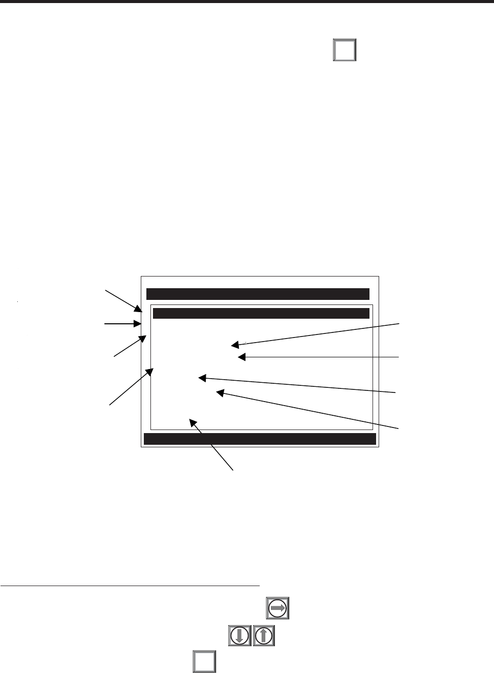
4-1
1010NFM-3J
Section 4
4. THE METER FACILITIES MENU AND GRAPHIC DISPLAY SCREEN
Meter Facilities functions are available immediately after pressing . The Meter Facilities menu
provides global control that enables you to identify and activate the following functions and features of
the hardware supported by this model.
zSelect data entry and meter output in either English (default) or metric units.
zCustomize the default pipe and transducer tables to suit your requirements.
zOutput, display, erase and select a memory management method for the Datalogger.
zDetermine the amount of memory available.
zVerify/Adjust the analog output voltage and current using a multimeter.
zVerify/Adjust the analog pulse output using a frequency counter.
zCalibrate the RTD temperature sensors.
zSet the system clock/calendar.
zObtain detailed software/hardware identification.
4.1 PREFERRED UNITS
The selection you make in this menu cell becomes the default units for all menu items and data
outputs. You can choose either English or metric units. The factory setting is English.
To specify metric default units for all meter functions:
To access the Preferred Units option list press
Move the cursor to [Metric] by pressing
To register your selection press ENT
MENU
This menu allows you
to specify default
measurement units.
This menu allows you
to create or edit pipe
and transducer tables.
This menu allows you
to work with and
select a Datalogger
storage method.
This menu allows you to
calibrate the RTD
Temperature Sensors.
This menu shows detailed information
about this model's hardware and software.
This menu allows
you to view the
number of data
memory bytes.
This menu allows
you to fine-tune the
analog outputs.
This menu allows you
to set the system
clock/calendar.
This menu allows you
to select RS-232 port
parameters.
Siemens Dual Path SITE 1
Table Setups
Datalogger Control
Memory Control
Analog Output Trim
RTD Calibrate
Clock Set 09.02.99 09.30.06
RS-232 Setup 9600 Odd 7
Backlight On
System Info
Preferred Units English
Meter Facilities
Select Default Units for all Menus
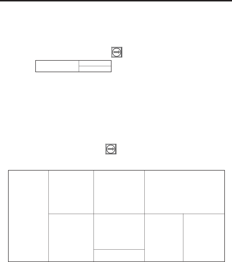
4-2
1010NFM-3J
Section 4
4.2 THE TABLE SETUPS MENU
The Table Setups menu allows you to pre-condition your pipe table and transducer types. The edits
made in Table Setups become the default settings for creating a new site. Transducers “marked” in the
Transducer Types menu will be preferentially selected when the meter recommends transducers
during the automatic Pick/Install Transducer routine.
To access the Table Setups menu press
*Note: The highlighted selection in the above table illustrates how to choose the ASA Stain-
less Steel Pipe Class and all its available Pipe Name selections. All other Pipe Classes
(e.g., ASA Carbon Steel) listed can be selected in the same manner.
(continued)
Create/Edit Pipe Choose Pipe Class ASA Stainless Steel*
ASA Carbon Steel
ASA Plastic
Metric DN Steel
Metric SGP Steel
Cast Iron Table
Ductile Iron Table
Copper Tube Table
Choose Pipe Name ASA Stainless Steel* ASA Carbon Steel ASA Plastic
1SS10 1CS40 1P40
2SS10 1CS80 1P80
3SS10 2CS40 2P40
4SS10 2CS80 2P80
6SS10 3CS40 3P40
8SS10 3CS80 3P80
Metric DN Steel 4CS40 4P40
50DN 4CS80 4P80
Ú
Ú
Ú
Ö
Ö
Ú
ÚÚÚ
Ö
Ö
PIPE TABLE MENU STRUCTURE
Ú
ÖÚ
Table Setups Pipe Table
Transducer Type
4.2.1 PIPE TABLE
The factory-programmed pipe table describes over sixty standard English and metric pipes. The table
can save you programming steps by loading all required data at once from option list selection. The
Pipe Table configuration is [PIPE CLASS Î PIPE NAME]. Pipe Class presents a list of standard metric
and English Pipe classifications. Selecting a class (e.g., ASA Carbon Steel) conditions the Pipe Name
option list to all the stored pipes within that class (see Menu Chart above). Selecting a pipe by its name
(e.g., 2SS10) loads a description of that pipe in the remaining menu cells. Note that liner data is not
provided. If your pipe is lined, then you will be required to enter the liner material and its thickness
manually.
To access the Pipe Table menu press

4-3
1010NFM-3J
Section 4
4.2.2 CREATE/EDIT PIPE
The Pipe Table provides the primary data that the system uses to operate with different classes of
pipes. This menu allows you to edit the pipe table by modifying any existing pipe or add an entirely new
pipe.
An example of how to use the Create/Edit Function:
To access the Create/Edit menu press
To access the Pipe Class option list press
100 DN 6CS40 6P40
200 DN 6CS80 6P80
400 DN 8CS40 8P40
800 DN 8CS80 8P80
Metric SGP Steel 10CS XS 10P XS
20A-SGP 10CS40 10P40
25A-SGP 12CS STD 12P STD
32A-SGP 12CS XS 12P XS
40A-SGP 16CS STD 16P STD
50A-SGP 16CS XS 16P XS
65A-SGP 18CS STD 18P STD
80A-SGP 18CS XS 18P XS
90A-SGP 20CS STD 20P STD
100A-SGP 20CS XS 20P XS
125A-SGP 24CS STD 24P STD
150A-SGP 24CS XS 24P XS
175A-SGP 30CS STD 30P STD
200A-SGP 30CS XS 30P XS
225A-SGP 36CS STD 36P STD
250A-SGP 36CS XS 36P XS
300A-SGP Cast Iron Table Copper Tube Table
350A-SGP 6” cls C 1” type M
400A-SGP 10” cls C 1” type K
450A-SGP 12” cls C 1” type L
500A-SGP 16” cls C 2” type M
20” cls C 2” type K
Ductile Iron Table 2” type L
6” cls 52 4” type M
8” cls 52 4” type K
10” cls 52 4” type L
12” cls 56” 6” type M
16” cls 52 6” type K
24” cls 52 6” type L
Outer Diameter (in) x.xxx (numeric entry)
Wall Thickness x.xxx (numeric entry)
Liner Material None
Cement
Coal Tar
Enamel
Glass
Plastic
HDPE
Teflon
Rubber
Liner Thickness x.xxx (numeric entry)
Delete Pipe Choose Pipe Class *See Create/Edit Pipe
Choose Pipe Name *See Create/Edit Pipe
Choose Pipe Name
Ö
Ö
Ú
Ö
Ú
ÚÚ
ÚÚ
Ú
Ö
ÖÚ
ÖÖ
Ö
Ú
Ö
Ö
PIPE TABLE MENU STRUCTURE (continued)
Ö
Ö
Create/Edit Pipe Ö
Ú
Ú

4-4
1010NFM-3J
Section 4
Scroll the option list to a class that provides the closest match to your pipe press
To select the Pipe Class press . This moves the highlight to Choose Pipe Name.
To access the Pipe Name option list press .
Scroll the option list press to a pipe name and press to select it.
This loads Outer Diameter and Wall thickness for the Selected Pipe.
The highlight moves to Outer Diameter. Press to enable numeric entry. Type the actual
pipe OD using the appropriate English or metric units. Press to store the OD. The
highlight moves to Wall Thickness.
Press to enable numeric entry. Type the actual wall thickness using the appropriate
English or metric units. Press to store the wall thickness.
Select a Liner Material and enter its thickness (if required).
Press to leave the Create/Edit Pipe menu. This triggers the Save Pipe pop-up Window.
Note that the second line lists the name of the selected pipe. Press and then press
to use this name.
To use a new name, press and then use the appropriate arrow keys to rename the pipe
(8 chars. Max.). Press . This adds the new pipe to the pipe class.
4.2.3 DELETE PIPE
This menu allows you to remove any of the pre-loaded pipes within a class from a pipe table. We
recommend that you use this function only to delete pipes that you have added so as to preserve the
factory presets.
To delete a Pipe from the Pipe Table
To access the Delete Pipe menu press . To access the Pipe Class option list press
Scroll the option list press to the class that contains the pipe to be deleted.
To select the Pipe Class press . This moves the highlight to Choose Pipe Name.
To access the Pipe Name option list press .
Scroll the option list to the pipe to be deleted by pressing .
To remove it from the pipe table press .
4.3 TRANSDUCER TYPE MENU
During the Transducer Install procedure, System 1010 analyzes the entered pipe and liquid data,
then automatically generates a list of the transducer sizes most suited for the application.
ENT
ENT
ENT
ENT
ENT
ENT
ENT
ENT

4-5
1010NFM-3J
Section 4
The Transducer Type menu allows you to place “marks” next to any transducers that you may want the
meter to consider preferentially during its recommendation routine. These transducers will be included
on the recommended list, which appears from on the reverse-video prompt line at the top of the display
screen. The left-most transducer on the list is the most applicable while the right-most transducer on
the list is the least applicable.
To mark Transducers:
Access the Transducer Type menu by pressing
Scroll the highlight by pressing to a transducer type (e.g., 1011H High Precision) then
press to access the size option list.
Scroll the option list by pressing and then press to “mark”desired transducers.
Note that a plus sign (+) appears before each “marked” transducer.
If you want to clear a “marked” transducer, move the highlight to the transducer then press
Note that this removes the plus sign.
To leave an option list press .
ENT
CLR
Transducer Type 1011 Universal A1
A2
B1
B2
B3
C1
C2
C3
D1
D2
D3
E1
E2
E3
1011H High Precision A1H
A2H
A3H
B1H
B2H
B3H
C1H
C2H
D1H
D2H
D3H
D4H
991 Universal 0A
0
1
2
2A
3
3A
4
4A
5
5A
ÖÖ
Ö
Ö
Ú
Ú
Ú
Ú
Ú
Ú
Ú
TRANSDUCER TYPE MENU STRUCTURE

4-6
1010NFM-3J
Section 4
4.4 THE DATALOGGER CONTROL MENU
The Datalogger Setup menu in the Channel Setup menu provides the Datalogger controls for the
meter’s measurement channels. It allows you to enable usage, select data items/ alarm events, a
logging interval and a destination for your Datalogger reports. While the Datalogger Setup menu is
measurement channel specific, this Datalogger Control menu provides global control functions. This
means that the settings made here apply to all measurement channels, meter types, operating modes,
etc. This is possible because the meter stores logged data in a single file. This is significant for dual-
channel systems, since the logged data from both channels are combined. Therefore, select the Site
ID item for each channel to be logged.
Datalogger Control allows you to select a Circular Memory mode that will over-write the oldest Datalog-
ger data automatically when the Datalogger memory becomes full due to the data compression scheme
employed. Note that this is only available for dual-channel systems. The [Est Log Time Left] menu
view-only menu cell shows an estimate of the hours and minutes of logging time remaining. This only
applies to non-circular datalogging. Selecting Circular memory blanks this field. For convenience sake,
the Display Datalogger command is essentially a duplicate of the menu cell in Datalogger Setup. It
sends Datalogger data to the graphic screen with or without line wrapping. For dual-channel systems
with logging enabled on both channels, a screen dump from menu will show data from both channels.
The Output Datalogger command sends data to an external device via the RS-232 serial port. Data
transmitted from this menu will be from both channels of a dual-channel system. The Clear Datalogger
command erases the entire Datalogger file. For dual-channel systems, you are cautioned not to use
this command if your intention is to clear the logged data of only one channel.
To access the Datalogger Control Menu press
4.4.1 DISPLAY DATALOGGER
This menu cell allows you to send the Datalogger contents to the display screen. This command is
effective only after a successful install. You can set the report to scroll on the screen with or without
line-wrap. Selecting line wrap, forces a line feed after approximately 40 characters. In addition, you
have to enable datalogging and then select items in the Datalogger Setup menu. Note that this com-
mand transmits the data from both channels.
To send Datalogger contents to the display screen:
To access the Display Datalogger option list press
Scroll cursor to either [Line Wrap] or [No Line Wrap] by pressing
DATALOGGER CONTROL MENU STRUCTURE
Datalogger Control Display Datalogger Off
Line Wrap
No Line Wrap
Output Datalogger No
Yes
Circular Memory No
Yes
Est. Log Time Left —:—
Clear Datalogger No
Yes
ÖÚ
Ö
Ú
Ö
Ú
Ö
Ö
Ö
Ú
Ú

4-7
1010NFM-3J
Section 4
To view Datalogger contents press
To return to Datalogger Control press
4.4.2 OUTPUT DATALOGGER
This menu cell allows you to send the Datalogger contents to an external device (usually a computer
or printer) via the meter’s RS-232 Serial I/O port. This command is effective only after a successful
install. In addition, you have to enable datalogging and select data items in the Datalogger Setup menu.
Note: This command sends the data collected by both channels of a dual-channel system. Therefore,
you should include [Site ID] (current site setup name), [Date] and [Time] in your report so that you can
identify the source of each report.
The meter interfaces with most serial printers or personal computers. Siemens offers the model 996P
portable serial printer. You must use the proper cabling between the flow computer and the external
device. In addition, you must configure the RS-232 Setup correctly. You should turn off the Datalogger
function before you transmit an extensive printout. This will avoid contaminating the printout with new
Datalogger data. Datalogger reports are sequential ASCII text files.
NOTE: The meter suspends flow measurement while it transmits serial data.
To send Datalogger contents to the RS-232 Serial Port:
Check the flow computer-to-external device connections and your RS-232 Setup parameters
(see RS-232 Setup).
To access the Output Datalogger option list press
Scroll the cursor to [Yes] by pressing
To transmit Datalogger contents to external device via the serial port press
To stop printout press
4.4.3 CIRCULAR MEMORY
In its default mode, the Datalogger collects data until its memory becomes full. At that time the flowme-
ter suspends data logging and cannot resume until the datalogger memory is cleared (see Clear
Datalogger command). Multi-Channel systems include Circular Memory and Single Channel systems
do not. Circular Memory allows the Datalogger to ”‘write over” its oldest records when memory reaches
full capacity. If you enable Circular Memory, you are assured of always collecting the most recent data.
But, also remember that you will lose the oldest Datalogger reports. Note further that invoking Circular
Memory deletes the current contents of the Datalogger.
NOTE: To avoid potential data loss, the flowmeter prevents you from altering the Circular
Memory setting when a channel is active.
To setup and enable Circular Memory:
The Datalogger Mode menu must have the [Memory] menu cell selected.
Datalogger items must be selected (e.g., Site ID, Date, Time, etc.).
All active channels in the Channel Setup menu must be disabled. To disable active
channels, select the [Channel Enable] menu cell and then [No].
ENT
ENT
MENU

4-8
1010NFM-3J
Section 4
In the Datalogger Control menu, select [Circular Memory].
Press to access the [Circular Memory] option list.
Move the cursor to [Yes] by pressing
To store selection press
Lastly, re-enable the channels that you disabled earlier to begin logging.
4.4.4 EST LOG TIME LEFT
Est Log Time Left is a “view-only” menu cell that shows an estimate of the amount of Datalogger time
remaining in hours and minutes. This menu cell becomes active after you enable datalogging. Select-
ing Circular Memory and/or event-based datalogging (see Datalogger Setup), blanks the field [Est Log
Time Left] and is based on the log interval and data selections made in the Datalogger Setup. For
Single-Channel flowmeters, this time is an estimated minimum since data compression is employed
for improved storage efficiency.
4.4.5 CLEAR DATALOGGER
If you use the Datalogger in its default mode, eventually you will use all the memory available for
Datalogger storage. When this occurs, you will not be able to log more data until you free up the
memory. The Clear Datalogger command erases ALL stored Datalogger data. Therefore, you should
evaluate the currently stored data, and print any valuable information before using this command.
Note: Saved Sites also consume datalogger RAM.
To clear Datalogger Data Memory:
To access the Clear Datalogger option list press
Move the cursor to [Yes] by pressing
To clear the memory press
4.5 THE MEMORY CONTROL MENU
Memory Control is a reference menu that shows the amount of bytes of data memory left. The data
memory capacity depends on the number and complexity of the site setups stored in memory and the
size of the current datalogger file. Capacity is also affected by the RAM option with which your 1010 is
equipped with - either 900k expanded or 170k standard RAM.
Memory Map: Selecting YES for this item enables a snapshot display of current memory usage. In this
display, the asterisk indicates a used block, a space indicates a free block, while a dash character
indicates unused filler.
Defragment: Selecting YES for this item consolidates memory data blocks into contiguous storage;
collapsing the filler regions. You may be able to use an additional block for site or datalogger storage as
a result. Use this command if you seem to be out of memory even though the Data Memory Left item
indicates free capacity.
Data Memory Left: This view only menu cell shows
the minimum remaining number of characters avail-
able for Datalogger and site storage. When the Data-
logger is enabled for circular mode, the meter allo-
cates all of memory except for two conventional
empty sites worth for datalogger use.
ENT
MEMORY CONTROL MENU
Defragment No
Yes
Data Memory Left XXXXX
Memory Map Yes
No
Ö
Ö
ÖØ
Ø
Ø
ENT
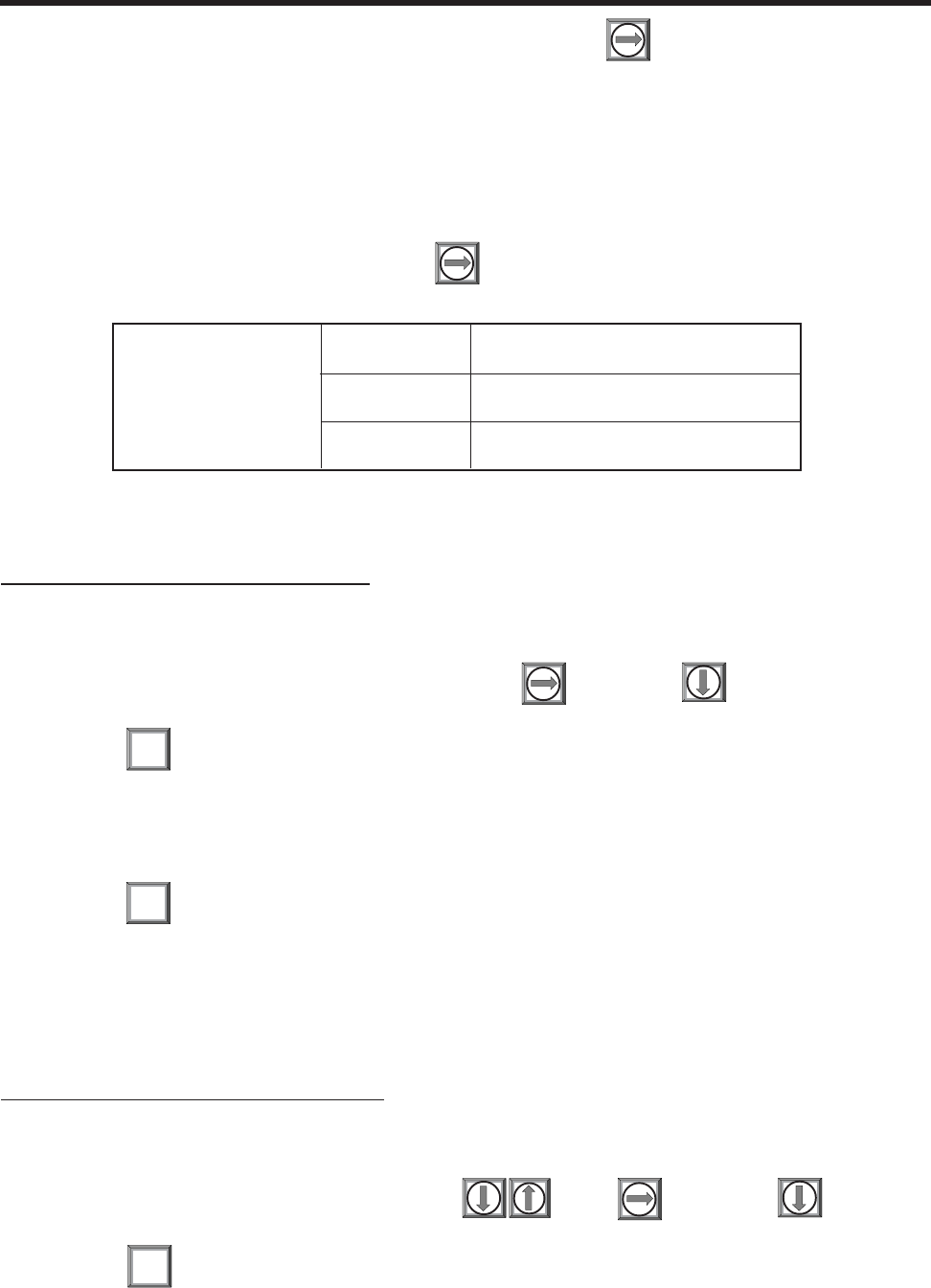
4-9
1010NFM-3J
Section 4
To view the amount of data memory bytes available press
4.5.1 THE ANALOG OUTPUT TRIM MENU
Analog Output Trim allows you to fine-tune the meter’s analog voltage and current outputs using a
multimeter connected to the output under test. In addition, you can use a frequency counter to fine-tune
the meter’s pulse rate output.
NOTE: The current, voltage, and Pgen trimming will be limited by the 12-bit resolution of the
meter’s D/A Convertor (DAC).
To access the Analog Output Trim menu press
4.5.2 CURRENT OUTPUT TRIM (Io1 & Io2)
(Note: Can be trimmed to within .005 mA of nominal.)
To calibrate a current output (Io1 or Io2):
Set up the multimeter to read Amps, then connect it to the supply and return terminals of the
current output under test.
Move the highlight to the port to be tested, press , then press to move the cursor
to Trim @ 4mA.
Press . This triggers a 4.00 mA pop-up window. The multimeter should now be
reading 4.00 mA.
If the multimeter reading does not match, use the numeric keys to type in the multi-
meter reading.
Press to register setting. This adjusts the meter’s DAC (digital-to-analog converter) so
that a 4mA output corresponds with 4mA on the multimeter.
Re-check the multimeter to make sure that it is now reading 4mA.
4.5.3 VOLTAGE OUTPUT TRIM (Vo1 & Vo2)
(Note: Can be trimmed to within .0025 V of nominal.)
To calibrate a voltage output (Vo1 or Vo2):
Set up the multimeter to read volts, then connect it to the supply and return terminals of the
voltage output under test.
Move the highlight to the port to be tested , press , then press to move
the cursor to Trim @ 2V.
Press . This triggers a 2.00 Volts pop-up window. The multimeter should now be reading
2.00 Volts.
ENT
ENT
ENT
ANALOG OUTPUT TRIM MENU STRUCTURE
Analog Output Trim Io1 (Io2) Operate
Trim @ 4mA Indicated mA = x.xx
Vo1 (Vo2) Operate
Trim @ 2V Indicated V = x.xx
Pgen1(Pgen2) Operate
Trim @ 1kHz Indicated Hz = xxxx
Ö
Ú
ÖÚ
ÖÚ
Ö
Ö
Ö
Ö
Ö
Ú
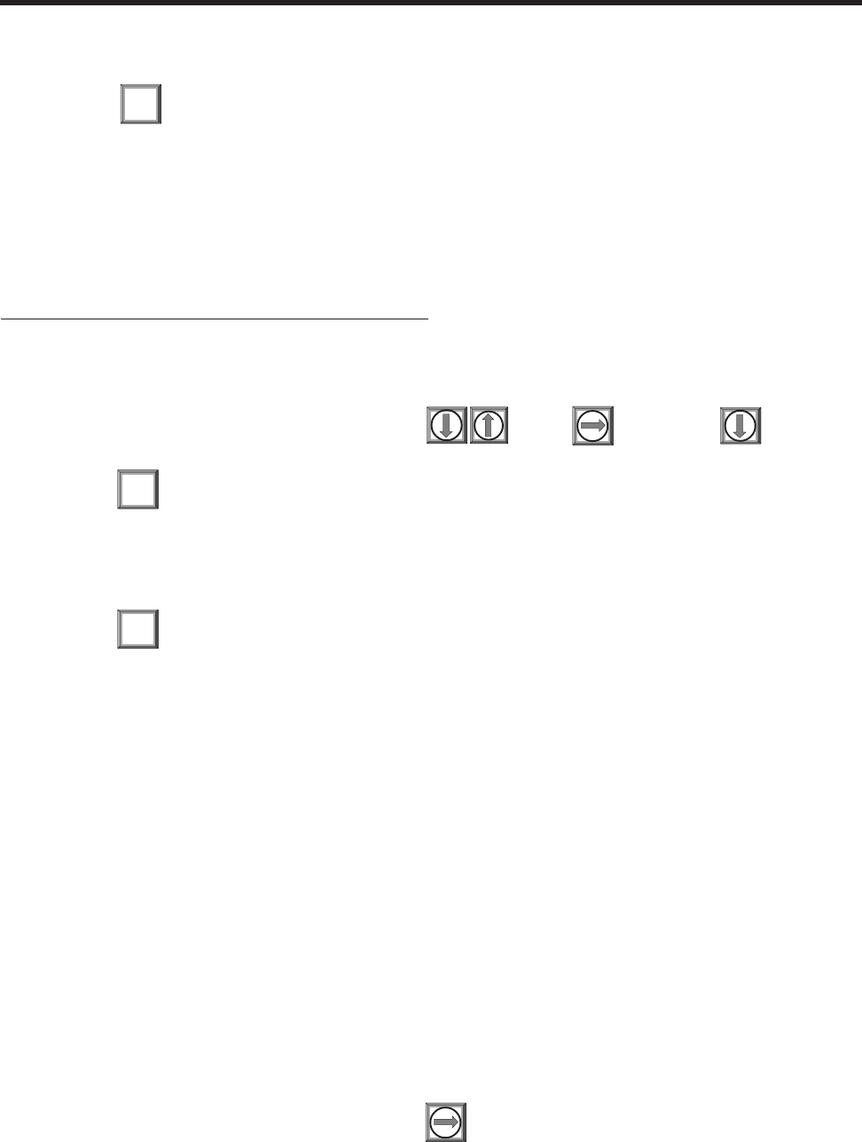
4-10
1010NFM-3J
Section 4
If the multimeter reading does not match, use the numeric keys to type in the multimeter read-
ing.
Press to register setting. This adjusts the meter’s DAC (digital-to-analog con-
verter) so that a 2.00 Volts output corresponds with 2.00 Volts on the multimeter.
Re-check the multimeter to make sure that it is now reading 2.00 Volts.
4.5.4 PGEN OUTPUT TRIM (Pgen 1 & Pgen 2)
(Note: Can be trimmed to within 1.25 Hz of nominal.)
To calibrate a pulse rate output (Pgen1 or Pgen2):
Connect a frequency counter to the supply and return terminals of the pulse rate output under
test.
Move the highlight to the port to be tested , press , then press to move
the cursor to Trim @ 1kHz.
Press . This triggers a 1 kHz pop-up window. The frequency counter should now be
reading 1 kHz.
If the frequency counter reading does not match, use the numeric keys to type in the frequency
counter reading.
Press to register setting. This adjusts the meter’s DAC (digital-to-analog converter so
that a 1 kHz output corresponds with 1 kHz on the frequency counter.
Re-check the frequency counter to make sure that it is now reading 1 kHz.
4.6 THE RTD CALIBRATE MENU (optional)
The RTD Calibrate Menu appears on all 1010N models. Use this menu to calibrate the 991T or 1011TN
RTD Temperature Sensors to an external standard. It is important to note that the RTD temperature
sensors are factory-calibrated for high accuracy. We recommend that before deciding to perform the
calibration, check the current RTD reading in [Diagnostics/Liquid Data]. You may find that you do not
even need to calibrate the sensor. In any case, make sure that the temperature reading stabilizes
before proceeding further. The RTD Calibrate menu allows you to perform an external calibration,
which can be accomplished either by data entry of the current RTD temperature or by a 320F (00C) Ice-
Bath procedure. You can switch between the intrinsic and external calibration modes at any time.
NOTE: If you perform an external temperature calibration, you should mark and record the
location of each connector and sensor-cable. Once you have re-calibrated the tem-
perature sensors, changing the sensor/connector orientation established during the
procedure may void the calibration.
To access the RTD Calibrate menu press
ENT
ENT
ENT
4-11
1010NFM-3J
Section 4
4.6.1 RTD CALIBRATION BY DATA ENTRY
The RTD Calibrate menu allows you to adjust the intrinsic RTD reading to match an external reference
thermometer by directly entering its reading. Only perform this procedure while the RTD under test is
installed and currently measuring temperature.
To enter the current RTD temperature
Move the highlight to the RTD you want to calibrate (RTD1 or RTD2).
To access the RTD option list press .
Move the highlight to [User Cal] or [Factory] Cal then press . This triggers thepop-up
window:
ENT
To enable numeric entry press , then type in the reading of the reference thermometer
(e.g., 72.0).
ENT
To recalibrate the RTD sensor . To verify the calibrated reading, go to [Diagnostics/Liquid
Data] to check the current RTD output. Make sure that it coincides with the reading of the
reference thermometer. Repeat for the other RTD if necessary.
RTD Calibrate RTD 1 Factory
User Cal
RTD 2 Factory
User Cal
ÖÖ
Ö
Ú
Ú
RTD CALIBRATE MENU STRUCTURE (Single Channel 1010)
To perform a 32ºF (0ºC) RTD Calibration:
Immerse RTD sensor in deionized water and ice mixture. Stir the mixture costantly.
Move the highlight by pressing to the RTD you want to calibrate (RTD1 or RTD2).
To access the RTD option list press . Move the highlight to [User Cal] then press .
This triggers the pop-up window.
ENT
4.6.2 ICE BATH RTD CALIBRATION
Use distilled, deionized water and ice mixture at 0ºC (32ºF) equilibrium for an ice bath.
Ensure temperature with a reference thermometer. Siemens can not assume responsibility for the
incorrect design, construction or operation of an Ice Bath.
NOTE: Factory Calibration provides an additional prompt after a new temperature is entered:
[Are you Sure? No Yes]. It is recommended that you use [User Cal] to avoid alteration
of preset factory calibration.
CAUTION: DO NOT ALLOW AN RTD SENSOR TO MAKE DIRECT CONTACT
WITH ICE DURING AN ICE BATH CALIBRATION.
Calib @ deg F
=72.0
Calib @ deg F
=32.0
4-12
1010NFM-3J
Section 4
When you are sure that the RTD Sensor is at 32ºF (0ºC), press to recalibrate the RTD sensor. To
verify the calibrated reading, go to [Diagnostics/Liquid Data] to check the current RTD output. Make
sure that it coincides with the reading of the reference thermometer. Repeat for the other RTD if nec-
essary.
ENT
4.7 THE CLOCK SET MENU
The Clock Set menu allows you to set the time and date. The meter uses its internal clock/calendar to
record the real-time when certain data and diagnostic events occur. In addition, the clock/calendar
provides the Datalogger and Stripchart date and time stamps.
4.7.1 DATE
The Date command sets the month, day and year for the meter’s internal clock/calendar. Enter the
date using the [MM.DD.YY] format. Replace MM with two digits to indicate the month. Replace DD with
two digits to indicate the day. Replace YY with two digits to indicate the year. Type the period (.) sepa-
rator between each set of digits. For example, you would enter December 7, 1997 by typing 12.07.97.
You can use the <Right Arrow> to move the cursor back to a number if you need to re-type it. Press the
<CLR> key to remove the current setting.
To set the Date:
To enable numeric entry press
Use the Numeric keys to type the date (MM.DD.YY).
To store the date press . This moves the cursor to [Time].
4.7.2 TIME
The Time command sets the hours and minutes for the meter’s internal clock/calendar. Enter the time
using the [HH.MM.SS] format. Replace HH with 2 digits to indicate the hour (use 24-hr. clock format).
Replace MM with 2 digits to indicate the minutes. Replace SS to indicate the seconds. You also have
to type the period (.) separator between each set of digits. For example, you would enter ten minutes
after two o’clock in the afternoon by typing: 14.10.00 You can use the <Right Arrow> to move the cursor
back to a number if you need to re-type it. Press the <CLR> key to remove the current setting.
ENT
Calib @ deg F
=32.0
Clock Set Date xx.xx.xx (date entry)
CLOCK SET MENU STRUCTURE
Time xx.xx (time entry)
Notice:
All flowmeters include a real-time clock to provide a convenient date/time stamp for display screens and
datalogger reports. The operating system does not rely on the date and time-of-day for any flowmeter opera-
tion. Therefore, the “Turn Of The Century” will have no effect on the proper functioning of any of our systems.
Although we limit the year to 2 digits in all our displays, 1010’s datalogger reports are Y2K complaint using an
industry standard algorithm to form a 4 digit year field.

4-13
1010NFM-3J
Section 4
To set the clock:
To enable numeric entry press
Use the numeric keys to type the time (HH.MM).
To store the time press . This moves the cursor to RS-232 Setup.
4.8 RS-232 SETUP
Use the RS-232 Setup menu to set the operating parameters of the serial I/O port. Settings include
baud rate, parity, data bits, line feed, network ID number and waiting period before a RTS time-out.
Only activate the RS-232 output if you intend to transmit serial data. This will avoid burdening the
system with unnecessary data transferals while it is performing flow computations.
NOTE: The RS-232 stop bit implementation is fixed. If you are using a communication pro-
gram, such as Windows 3.xx Terminal or Windows 95/98/NT/2000/XP HyperTerminal,
that includes a field for stop bits, select 1 stop bit.
ENT
RS-232 SETUP MENU STRUCTURE
RS-232 Setup Baud Rate 300
1200
2400
4800
9600
38400
Parity None
Odd
Space
Even
Mark
Data Bits 7
8
Line Feed No
Yes
Network ID xx (numeric entry)
RTS Key Time 0.2 Sec.
0.4 Sec.
0.6 Sec.
0.8 Sec.
1.0 Sec.
2.0 Sec.
3.0 Sec.
4.0 Sec.
Ú
Ö
Ú
Ö
Ú
Ú
Ö
Ú
ÖÚ
Ö
Ö
Ú
Ú
Ö
Ú
Ú
Ú
Ö
Ö
Ö
Ö
Ö
4.8.1 BAUD RATE
The Baud Rate menu cell sets the asynchronous serial transmission data transfer rate of the RS-232
port. It provides a selection of standard baud rates up to 38,400 baud. The selected baud rate must
match the baud rate setting of the receiving external device. The factory-set baud rate is 9600.
To change the Baud Rate:
To access the Baud Rate option list press

4-14
1010NFM-3J
Section 4
Move the cursor to the required baud rate by pressing
To store selection press . This moves the cursor to [Parity].
4.8.2 PARITY
Parity is a simple method to check the accuracy of an asynchronous serial data transfer. The parity
setting tells the meter how to format the data words it sends to an external device. Parity is usually an
additional bit added to each data word. For example, if you select [EVEN], the total sum of all the bits in
a single data word (including the parity bit) will always be an even number.
The Parity option list includes all the standard parity settings for asynchronous serial transmission.
The selected parity must match the parity setting of the receiving external device. Some devices ig-
nore parity entirely; therefore, the option list includes [None]. The factory setting is [None].
To edit the Parity Setting:
To access the Parity option list press
Move the cursor to the required parity setting by pressing
To store the data press . This moves the cursor to [Data Bits].
4.8.3 DATA BITS
You can specify how many data bits the meter uses to format data words for serial transmissions. The
default setting is [7]. Note that the 996P portable printer requires a word length of [8].
To set the Data Word Length:
To access the Data Bits option list press
To move the asterisk to the required bit setting press
Press to store data. This moves the cursor to [Line Feed].
4.8.4 LINE FEED
Some serial devices (printers, terminals, etc.) insert a line feed automatically after they receive a
carriage return character. When communicating with these device types, you should set the Line Feed
to [OFF]. This instructs the flow computer to send a carriage return character without adding a line
feed to avoid creating an additional blank line after each carriage return. Setting the Line Feed to [ON]
tells the flow computer to insert a line feed character after each carriage return that it transmits. This
may be necessary to avoid the constant “wrapping” of transmitted data onto a single line. The factory
setting is [NO] (line feed disabled). Note that the 996P portable printer requires [NO].
To enable (or disable) Line Feed:
To access the Line Feed option list press
Press to move the asterisk to [Yes] Line feed enabled, or [No] Line feed disabled.
ENT
ENT
ENT

4-15
1010NFM-3J
Section 4
To store the data press . This moves the cursor to Network ID.
4.8.5 NETWORK ID
The [Network ID] menu cell stores an identification number to facilitate host computer polling when you
use this system in a network environment. The Network ID number can be any value other than 0
(zero). The default setting, zero, disables the network function. Note that entering a non-zero Network
ID number suspends all routine Datalogger activity regardless of any selected options.
NOTE: If you are using the flowmeter for a “stand-alone” application, you must keep the zero
Network ID number.
To assign a Network ID number
To enable numeric entry press .
Use the numeric keys to type the Network ID number.
To store Network ID press . This moves the cursor to RTS Key Time.
4.8.6 RTS KEY TIME
During a serial transmission session, you can select how long the flow computer holds its request-to-send line
high until it receives a clear-to-send signal. If the RTS time expires, the 1010 will return its RTS line low and abort
the transmission attempt. Data entry units are seconds. The default RTS key time is 0.2 seconds.
NOTE: The RTS Key Time function is only provided when the meter’s network ID number is
non-zero.
To set the RTS Key Time:
To access the RTS Key Time option list press
To move the asterisk to the required RTS time press
To store the data press
4.9 BACKLIGHT
This menu cell allows you to specify how long you want to maintain the backlighting for the LCD
Graphic Display. Select [On] for continuous illumination. Press the <Right Arrow> to access the option
list and then scroll to desired time delay (before turn-off).
Press to store your setting.
4.10 SYSTEM INFO
This menu provides general information about the flowmeter.
ENT
ENT
ENT
ENT

4-16
1010NFM-3J
Section 4
4.11 THE 1010 GRAPHIC DISPLAY SCREENS
The 1010 family Graphic Display Sub-System is a versatile resource which provides visual access to
all system variables and conditions. Depending upon your selection, details of the display my vary, but
all elements are always clearly labeled with units and variable names. You’re always free to move
through the displays by using the arrow keys. The meter will hold the last display selected indefinitely
or until the menu is selected by pressing the <Menu> key. When you again leave the menu, the last
selected display will be shown upon your return.
After completing the Site Setup, Check your local display screen to ensure that everything is operating
properly. The meter begins to measure flow as soon as you complete the transducer installation.
When you press to leave the menu, you will see the hybrid digital display screen (see page 4-
17). Note that it includes a digital flow, total numeric display and a Stripchart.
The StripChart Contains a number of special elements that deserve mention:
zThe spanning of the stripchart’s vertical axis obeys the same user settings that define the span
limits for the analog outputs. If the variable “pegs,” the numerical expression of that variable will
also peg.
zAlarm limits, or thresholds, are indicated by triangular cursors shown near the stripchart bar.
These are also defined in the Data Span/Set/Cal area of the menu.
zEach time the stripchart is altered in a manner that can cause misinterpretation of already dis-
played data (re-spanned, new interval, etc.), a vertical bar is drawn on the stripchart. Only the data
to the left of the vertical bar is correctly displayed.
zDue to limitations in display area, certain rate or total units may be displayed with fewer characters
than are needed for unambiguous interpretation. Consult the 1010’s Flow and Total Units menu
cells for clarification in these cases.
MENU
Version This is the meter’s operating system version number. The Technical Services
Group may request this number during consultations.
Reset Date/Time Shows the date and time of this meter’s last <F4> reset.
Op System P/N Meter’s operating system part number.
Checksum Operating System verifying code. The Technical Services Group may request this
number during consultations.
Code Software Compile Date/Time. Operating System identifier. The Technical Services
Group may request this number during consultations.
System Time Use to set system time and date. Format: xx.xx.xx xx.xx.xx
System Info Menu Structure
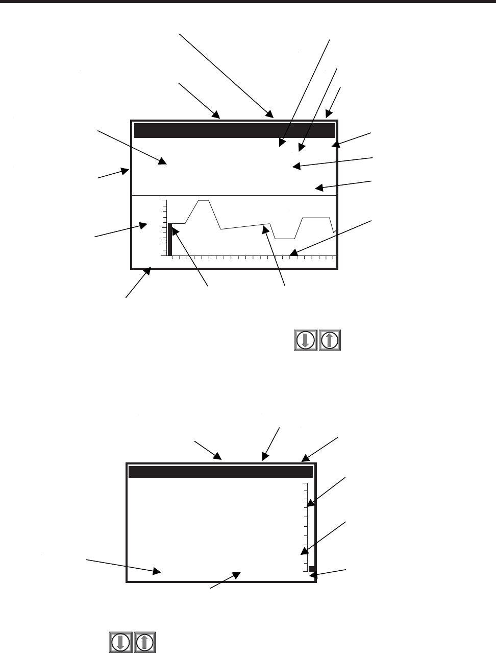
4-17
1010NFM-3J
Section 4
To switch the screen to the “big digits” display press
You can press to scroll between the available display screens.
14.35
Siemens 2 Channel [1] Unit#1
FLOW GAL/MIN
TOTAL GAL Vs
100.0
0.0
31.74
354.6597
Vf
1427
Site Setup Name
Percent of
Span Bar
Graph Display
Instantaneous
Volumetric
Flow Rate (%)
Selected Meter Type
(
Dual Channel Flow
)
Selected
Measurement
Channel
Flow Total
Measured Sonic
Velocity
Vfo
(Volumetric Average
Flow Output)
Stripchart
(Flow History)
Stripchart
A
larm Cursors
Siemens 2 Channel [1] Unit #1
FLOW: GAL/MIN Vs ALC AER
1286 63 2
NTOTAL: GAL
112.38
68.10
HI/LO
30.0
-30.0
Vs
11.40 9/26 12:45
Date & Time
Digital Flow Total
Percent of
A
eration
Detected
Site Name
Si
g
nal Stren
g
th
Instantaneous
Flow Rate
Active Alarm
Digital Average
Volumetric Flo
w
Select Meter Type
(Dual Channel Flow)
Selected
Measurement
Channel
Measured Sonic
Velocity (in m/s)
G/M
Totalizer Mode (NTOTAL)
Strip Chart
Data (Vfo)
Volumetric
Flow Rate

4-18
1010NFM-3J
Section 4
The flow display uses the first (prompt) line display for the purpose of identifying the type of meter
currently enabled (Dual Channel, Dual Path) and the channel from which the current display is derived
(1 or 2 for the physical channels and 3 for the computed or average channel in a dual-path meter). The
Site Name is displayed in the upper right-hand corner of the digital display.
9.73
UNIT #1 0.65
FLOW GAL/MIN
TOTAL GAL
75.30
- - - - - - - - - 17.12 09/28
11.01
FLOW GAL/MIN
TOTAL GAL 97.04
Dual Display Screen
0.20
Siemens 2 Channel [1] Channel 1
FLOW GAL/MIN
TOTAL KGAL Vs
89.68
G/M
0.00
0.12 Vfo
1474

5-1
1010NFM-3J
Section 5
5. SYSTEM 1010 APPLICATION NOTES
System 1010 is an extremely versatile transit-time flowmeter that operates with either non-intrusive
clamp-on or in-line (non-wetted) flow transducers. Please review the following application guidelines to
obtain the best service from this equipment.
System 1010 provides a simple menu-driven interface for site programming. During the installation
procedure, you tell the system what you need it to do. It will then verify the pipe and liquid conditions,
and based on your selections, optimize its operation automatically. However, the system cannot pro-
tect itself from critical data entry errors that you input. Its performance depends on the accuracy of the
information that you provide it.
For normal operation, the flow computer only needs a receive signal of sufficient amplitude to activate
its automatic gain controlled detection circuits. Severely adverse application conditions may reduce
system performance, or cause apparent operational failures. Finding the culprit that caused this can
usually also reveal an appropriate remedy. Should this still present a problem, call us for technical
assistance.
5.1 TO OBTAIN TECHNICAL ASSISTANCE
Our Technical Service Group provides assistance upon request. You can obtain toll-free
assistance from 8:30 until 5:00 o’clock EST by calling 800-275-8480. In addition, you can request help
via e-mail by contacting the Siemens Technical Service Group at TSG.ultrasonicflow@siemens.com.
The meter’s computer provides comprehensive diagnostics data. Using this data, our Engineers can
analyze the system in relation to the application in detail. Proper analysis will provide solutions to
virtually any application problem.
5.2 CONSIDERATIONS FOR CRITICAL APPLICATIONS
All flowmeters depend on site flow conditions and proper installation to achieve precise, critical flow
measurements. Unfavorable factors such as liquid non-homogeneity or stratification and aeration/
cavitation increase the possibility of reduced accuracy. This applies to all flowmeters, regardless of
their design, sophistication, expense and published intrinsic accuracy. These factors become critical
when applications involve custody transfer, tenant billing, and nuclear or other safety-related flows.
System 1010 flowmeters automatically compensates for adverse flow conditions to achieve extremely
high accuracy. This requires following the instructions for proper equipment selection, use of the cor-
rect clamp-on transducer or flow tube configuration, and paying close attention to installation instruc-
tions. Such judicious use implies expert equipment knowledge and experience, plus a thorough under-
standing of flow conditions.
If your application requires critical measurement accuracy, it is not realistic to simply install the flow-
meter and expect optimum performance. Carefully review your piping configuration, select the best
mounting location and install the transducers or flow tube in strict accordance with the published in-
structions. Even when the system is calibrated for enhanced precision at a flow laboratory, this does
not relieve you of the responsibility of adhering to the programming instructions and installation require-
ments. We recommend that all potential installers for critical applications participate in our training
programs. Another alternative is to commission our trained professionals to start-up the system for
you.

5-2
1010NFM-3J
Section 5
5.3 PIPE CONSIDERATIONS FOR CLAMP-ON TRANSDUCER
Clamp-on flow transducers operate on any round pipe that conducts sound. Suitable pipe materials
include most metals, plastics, glass and mandrel wound FRP. Pipes with a fine grain structure (e.g.,
carbon and stainless steel) conduct sound more freely than cast iron, ductile iron or copper pipes.
Nevertheless, all are usually acceptable. Unsuitable pipes include concrete or other non-homoge-
neous materials. Pipe liners are acceptable if they are sonically conductive and bonded solidly to the
inner wall of the pipe. The system operates successfully on pipes with cement liners that are “spun”
onto the pipe interior to exclude any air bubbles. Pipes with smoothly applied bituminous and epoxy
coatings are also acceptable. Plastic liners are universally acceptable, if they are in intimate contact
with the inner wall and not merely slipped within the pipe.
5.3.1 PIPE DIMENSIONS
Controlotron manufactures transducer assemblies to service pipes from 0.25" to 360" in outer diam-
eter. During the transducer install procedure, the flow computer will recommend transducer sizes
based on the site data that you enter. Pipes with OD-to-Wall thickness (OD/W) ratios greater than 10
to 1 are ideal applications. Operation on pipes with OD/W ratios of 7 to 1 (or less) are acceptable, but
may exhibit reduced stability and linearity. Generally, higher OD/W ratios provide better stability. If a
pipe has a low OD/W ratio, you should use the smaller of the recommended transducer sizes (if the
flow computer recommends two transducer sizes).
5.3.2 PICKING THE APPROPRIATE TRANSDUCER
To ensure that you select the appropriate transducers for your application, consider the pipe outer
diameter, temperature range and degree of precision required. Decide whether you need two indepen-
dent flow channels or if you have to operate the system in dual-path configuration for greater accuracy
and flow profile aberration immunity.
Initial transducer size recommendations are based on your pipe outer diameter, wall thickness and
pipe material entries. However, you can override the meter recommendations to accommodate spe-
cific situations. For example, you may own a set of transducers whose size does not appear on the
meter list. You may be able to use transducers on a pipe size outside of their nominal pipe OD range.
During transducer install, the flow computer recommends Spacing Indices (for spacer bars and mounting
tracks) or Ltn, (actual distance required between transducers). Once you mount transducers and
invoke the install routine, you can determine the suitability of your transducers by checking the signal
strength and comparing the reported sonic velocity with the actual sonic velocity of the liquid to be
measured.
NOTE: Transducer pairs must have matching serial numbers.
5.3.3 FLOW VELOCITY RANGE
System 1010’s flow velocity range with clamp-on transducers is at least ±40 ft/sec regardless of the
diameter of the pipe. Depending on application conditions, this range can extend to over 100 ft/sec.
This measurement range is greater than needed for virtually any application. For optimum accuracy at
very low flow rates and for small line sizes, consider using our 992DFT or 1011FT flow tubes.
5.3.4 OVERVIEW OF SYSTEM PERFORMANCE
Our system performance specifications are based on acceptable liquid sonic conductivity and other
pertinent application conditions. The diversity that characterizes liquid flow, makes it impossible for us
to cover all possible application conditions that have the potential to reduce performance. Performance

5-3
1010NFM-3J
Section 5
within specifications depends primarily on the receive signal’s signal-to-noise ratio and amplitude. The
information below may point to application conditions that could reduce system performance below its
normally high level.
5.3.5 ACCURACY
Although system accuracy is exceptional over a wide turndown ratio, at extremely low flow rates, a
small zero offset becomes a high percentage of actual flow. Obviously, the ultimate accuracy will be
obtained by performing an on-site flow calibration. A flow calibration can increase system accuracy to
between 0.3% to 0.5%, depending on application conditions.
Two common data-entry mistakes may reduce performance. If you enter an incorrect liquid viscosity
value, you could compromise the intrinsic flow profile compensation curve. Incorrectly identifying the
transducers will reduce accuracy. Measured sonic velocity (Vs) errors will usually reveal this problem
and by simply returning to the appropriate menu cells, entering the correct values, and then repeating
the transducer installation it will resolve it.
5.3.6 REPEATABILITY
Some applications require repeatability rather than absolute accuracy. System 1010 features excellent
repeatability specifications since its digital “no moving parts” design avoids the adverse effects of
hysteresis and other wear mechanisms typical of mechanical devices.
5.3.7 DATA STABILITY
Two main factors influence the system’s data stability: Data Scatter and Drift.
Data Scatter
Data scatter is a rapid variation in flow readings (within a span of about 0.1 to 5 seconds). Minimal data
scatter (approximately 0.01 to 0.03 ft/sec) is a natural by-product of digital computation that extracts
the extremely small difference in the up vs. down sonic transit time. Minimal data scatter will not influ-
ence the integrated flow total over periods as short as several minutes. Naturally, it will be a greater
percentage of the reading when the meter measures extremely low flow rates. Poor liquid sonic con-
ductivity may attenuate sonic signal to a level that increases data scatter. You should check the signal
level (Valc %) item on the Diagnostic Menu. Usually, this is indicated by a low Valc % value (less than
30).
System 1010 does not exhibit inertia since it has no moving parts. In addition, it takes readings ten
times per second. Therefore, it can detect and track very brief flow fluctuations that are beyond the
response capability of some conventional meters. This performance level is required for detecting very
fast and short flow transients or for a fast-response servo control loop application. However, you can
use the damping and slewing controls to smooth the output response if you want the system to ignore
rapid flow fluctuations or data scatter.
Data Drift
Drift is a defined as a long-term cyclical flow deviation resulting from the variation of liquid temperature
or liquid sonic velocity. Drift may be more noticeable when combined with a poor signal-to-noise ratio.
System 1010 is carefully designed to minimize the effects of drift. There are no drift-prone analog
phase-locked loop devices in the primary detection circuits. In addition, we use only the most stable
plastics or steel to construct our transducers.

5-4
1010NFM-3J
Section 5
5.4 FLOW CONDITIONS
Very rarely are real-world flow conditions uniform and predictable. Therefore, the 1010 operating sys-
tem provides a considerable degree of control over the stability/agility of the flow rate output. System
1010 is significantly more agile in tracking pressure wave induced Vs transients, and will recover from
mistracking more quickly and smoothly than any other competing transit-time flowmeter.
5.4.1 LOW FLOW RATES
Our 1010 Systems provide a flow resolution and measurement range that surpasses any other type of
flowmeter. Therefore, it operates superbly for low or high flow rate applications. However, with our
clamp-on systems, using the highest resolution when measuring a low flow rate may cause natural
data scatter to become a high percentage of the reading. Since it is data scatter, it will not contribute
any error to a totalizer reading accumulating for at least several minutes. However, if the flow rate is
extremely low (e.g., under 0.25 ft/sec) the minute zero drift retained by the system may cause an
observable performance decline. Therefore, if your application involves extremely low flow velocities,
and your line size is 2" or under, our 992DFT or 1011FT Flow Tubes might serve you best.
5.4.2 FLOW DATA SCATTER & DAMPING
The transit-time flowmeter’s ability to respond to the extremely fast flow fluctuations that characterize
“real” flow may surprise you. Most conventional flowmeters cannot detect these rapid flow fluctuations
since they are subject to unavoidable mechanical inertia. System 1010’s response speed is ideal for
tracking fast flow transients. However, if this performance is unnecessary, you can smooth the Sys-
tem 1010’s response time to suit any application.
System 1010 Damping and Slewing Controls
System 1010 can detect and display minute flow fluctuations that are always present, though not
usually detectable by typical flowmeters. This rapid response accommodates applications that require
the tracking of fast flow transients.
Time Average is a filter that controls the output damping (the number of samples averaged together to
produce the instrument’s primary rate output). It allows you to enter a value in seconds that the flow
computer uses to integrate its response to flow changes. Do not confuse this with the update speed of
analog outputs. This occurs every 0.2 seconds, regardless of the time average that you select. One
practical application is to set the time average damping so that the meter maintains a smooth output,
when it is installed downstream from devices (e.g., a positive displacement pump) that may cause
regular surges in the liquid flow.
SmartSlew is a digital signal processing method that generates a variable time constant based on the
real-time assessment of collected data. When the flow data exhibits a steady trend, SmartSlew ex-
tends the time constant resulting in very smooth data output. SmartSlew instantaneously reduces the
time constant whenever the trend of flow changes, even for a short duration. The flow output quickly
follows the slewing of actual flow. SmartSlew thus provides excellent data without sacrificing the fast
response required for precise flow control. Feel free to experiment with time average damping and
slewing factors to discover which settings optimize the collected data. With SmartSlew enabled, you
can create very smooth output graphs without losing the ability to respond to fast flow transients that
may be undetectable with the fixed time average filter enabled.

5-5
1010NFM-3J
Section 5
5.4.3 NOTES ON LIQUID CONDITIONS
Successful transit-time flow measurement depends on sonic transmit signals traveling through liquid
and arriving at the receive transducer without excessive attenuation. Receive signals can be scattered
by liquids carrying dispersed particulate matter, either of a solid, non-homogeneous or gaseous na-
ture. This is especially true if the dispersed material is of different sonic impedance than the base
liquid. Liquids that contain an excess of gas bubbles or mineral solids may prove to be unsatisfactory
transit-time applications. However, these liquids are perfectly suitable for Reflexor flowmetering. Liq-
uids containing dissolved gasses or dissolved organic solids will not cause any problems for transit-
time operation.
Most liquids are excellent sonic conductors, regardless of their electrical or optical properties. Al-
though highly viscous liquids exhibit a greater degree of sonic attenuation, System 1010 operates
perfectly with the vast majority of these liquids. The Valc % (signal strength) item on the Diagnostic
Menu is a good indicator of this condition. A low value (under 30) indicates a possible low liquid sonic
conductivity, or improper transducer installation.
5.4.4 ERRONEOUS LIQUID PARAMETER SPECIFICATION
The viscosity of the liquid is an important factor. It governs the degree of Reynolds Number compensa-
tion that the flow computer applies to the final rate output. Therefore, flow data errors could result if you
enter an inaccurate viscosity value. Controlotron’s Technical Service Department can provide reliable
viscosity data for most liquids.
5.4.5 LIQUID COMPATIBILITY
Since our clamp-on transducer systems never contact liquid, the issue of liquid compatibility only
applies to entrained gases or mineral solid content that might impair sonic signals Since System 1010
is designed to measure flow using both transit-time and Reflexor™ techniques, we can safely say that
it will operate most successfully on virtually all liquids.
5.4.6 AERATION
Undissolved gases, having very low sonic impedance, may cause sonic beam scattering. In large
quantities, they can reduce the sonic signal strength. Small bubbles, caused by cavitation, usually
provoke more signal loss than an equal quantity of large gas bubbles. Usually, the problem can be
alleviated by eliminating the cause. Aeration may be caused by a mixing tank, throttling valve cavita-
tion, or air suction upstream of the transducer location.
System 1010 can operate successfully with a larger amount of aeration than any other transit-
time flowmeter. It measures and reports the aeration level as the analog output, Vaer %. This repre-
sents the relative degree of aeration detected within the flow stream. Its computer reports the Vaer
level until it impedes operation and forces a Fault Alarm. The Vaer output accommodates applications
requiring an aeration indicator. The Vaer also appears on the display screen. The aeration percentage
can be used as an alarm relay set-point. You can set the aeration alarm setpoint such that it trips
before aeration reaches a level that impairs flow measurement.
NOTE: Before performing the installation routine, allow enough time for the liquid to flush out
all air trapped in the pipe.

5-6
1010NFM-3J
Section 5
5.4.7 SLURRIES
High-density undissolved solids (e.g., sand slurry) may cause application problems if present in suffi-
cient quantity to scatter the sonic beam significantly. Low-density solids, such as organic materials,
coal slurries and unaerated sewage sludge, are usually adequate sonic conductors and their sonic
impedance is very close to most liquids. Excessive mineral solids though could trigger the aeration
alarm.
5.4.8 TWO-PHASE LIQUIDS
Two-phase liquids (e.g., oil and water) cause some sonic beam scattering. However, these usually
conduct sonic beams sufficiently for proper operation (unless heavy aeration is present also). Two-
phase liquids with large quantities of different components, such as sand or free gas, could prove to be
too attenuative for transit-time operation. However, switching to Reflexor mode will keep the meter
operational under these circumstances.
5.4.9 VISCOUS LIQUIDS
Highly viscous liquids tend to “absorb” some of the energy of the sonic beam. This causes a reduction
of signal amplitude when compared to low viscosity liquids. However, most high viscosity liquids are
sufficiently conductive for acceptable operation. A low Valc % value usually indicates low sonic conduc-
tivity.
5.4.10 TEMPERATURE AND PRESSURE RATINGS
We rate our standard (universal) transducers for operation up to 250°F. We offer High (H) temperature
flow transducers rated for operation up to 375°F. We also manufacture Very High (VH) temperature
transducers for applications where the temperature exceeds 375°F, but is less than 450°F. Please
refer to Section 6 for flow tube pressure and temperature ratings.
5.5 OVERVIEW OF SYSTEM 1010N MEMORY RESOURCES
System 1010N’s memory resources include both Read-Only-Memory (ROM) and battery-backed Ran-
dom Access Memory (RAM). The ROM memory contains the system operating instructions, on-line
help text, default data, and the pipe, transducer and liquid tables.
The flowmeter uses 1 Megabyte of RAM (standard) to provide three discrete storage functions:
Active Memory - Site Storage Memory - Datalogger Memory.
Upon creating a site, the meter copies all ROM-based defaults into the meter’s operational database,
the Active Memory. This provides two advantages. First, RAM-based operation increases performance.
Second, this creates an immediate Site Setup, based on the meter’s defaults. To make the meter
operational, you just have to enter required data (e.g., pipe and transducer data) and edit other default
settings to suit your application. When you program the meter, all your entries are retained in the Active
Memory. This enables you to use the meter immediately after finishing a Site Setup. You’re not limited
to one set of site parameters. You can copy site data from Active Memory to Site Storage Memory.
Site Storage Memory provides permanent storage area for several inactive Site Setups. The multi-site
storage feature allows rapid reinstallation at many locations. All you have to do to reactivate an inactive
Site Setup is to recall it back into to Active Memory. However, be aware that this action over-writes ALL
the data residing in the Active Memory area.
The Datalogger logs data collected at preset intervals during operation. It uses the system RAM re-
sources independently of Active Memory and Site Storage Memory. Therefore, data movement be-
tween Active Memory and Site Storage memory will not affect it directly. However, all stored data shares

5-7
1010NFM-3J
Section 5
a common RAM pool. The meter allocates the actual amount of bytes available for each storage
function dependent on the demands of each facility. Therefore, an unusually large Datalogger file may
reduce the amount of site storage memory available. Storing several inactive site setups may reduce
the available logging capacity.
If you receive a [Memory Full!] message when you try to save a Site Setup, then you will have to delete
an obsolete Site Setup or clear the Datalogger Memory to make room. Another Datalogger memory
consideration applies to dual-channel systems, when both measurement channels are actively log-
ging data. Dual-channel meters store logged data from BOTH channels in a common file so you must
include Site ID for each line to identify the applicable measurement channel.
The 1010 also offers a Memory Map and Defragmenting command in the Meter Facilities area of the
menu as an aid in visualizing and maximizing the efficient utilization of your meter’s memory resources.
5.6 REFERENCE TABLES
The following tables provide reference data that may be required during the Site Setup.
Liquids/Oils Vs(m/s) Liquids/Oils Vs(m/s)
Acetate, Butyl (n) 1270 Ethanol 1180
Acetate, Ethyl 1180 Ethylene Glycol 1620
Acetate, Methyl 1150 Gasoline 1250
Acetate. Propyl 1180 Glycerine 1920
Alcohol 1440 Linalool 1400
Alcohol, Butyl (n) 1270 Linseed Oil 1770
Alcohol, Ethyl 1180 Methylethyl Ketone 1210
Alcohol, Methyl 1120 Motor Oil (SAE 20/30) 1487
Alcohol, Propyl (i) 1170 Paraffin Oil 1420
Alcohol, Propyl (n) 1220 Pentane 1010
Benzene 1330 Petroleum 1290
Benzol, Ethyl 1340 Trichlorethylene 1050
Butyrate, Ethyl 1170 Transformer Oil 1390
Carbon Tetrachloride 938 Turpentine 1280
Diethyl Ketone 1310
SONIC VELOCITY (in meters/sec) FOR COMMON LIQUIDS @ 68°F
Water 0 32 1402 Water 120 248 1519
10 50 1447 130 266 1503
20 68 1482 140 284 1485
30 86 1509 150 302 1466
40 104 1529 160 320 1440
50 122 1543 170 338 1412
60 140 1551 180 356 1390
70 158 1555 190 374 1360
80 176 1554 200 392 1333
90 194 1550 220 428 1268
100 212 1543 240 464 1192
110 230 1532 260 500 1110
Liquid Deg. C Deg. F Vs (m/s) Liquid Deg. C Deg. F Vs (m/s)
SONIC VELOCITY FOR PURE WATER @ VARIOUS TEMP. (meters/sec)

5-8
1010NFM-3J
Section 5
(continued)
Vps VALUES (in inches/second) FOR SOME COMMON METALS
Metal Vps (in/sec) Metal Vps (in/sec)
Aluminum 120,000 Magnesium O-1 120,000
AL 1100 (2S) 121,000 Magnesium ZK-60A-TS 120,000
AL 1100-0 (2S0) 122,000 Monel 107,000
AL 2014 (14S) 121,000 Molybdenum 132,000
AL 2024-T4 (24ST) 124,000 Nickel 118,000
AL 2117-T4 (17ST) 123,000 Steel, 302 Cres. 123,000
Brass 89,400 Steel, 347 Cres. 122,000
Brass, Alpha 79,500 Steel, 1020 128,000
Brass, Half Hard 80,700 Steel, 1095 126,000
Brass, Naval 83,500 Steel, 4150, Rc14 110,000
Bronze, Phosphor 87,800 Steel, 4150, Rc18 125,000
Cadmium 59,100 Steel, 4150, Rc43 126,000
Carpenter 20 Steel 117,900 Steel, 4340 126,000
Columbium 82,700 Tantalum 114,000
Columbium (10W, 10TN) 74,800 Tin 65,700
Constantan 104,000 Titanium 122,000
Copper 89,400 Titanium, T1 150A 124,000
Iconel 119,000 Titanium Carbide 203,000
Iron 127,000 Tungsten 113,000
Iron, Cast 110,000 Vanadium 109,000
Magnesium AM-35 122,000 Zinc 94,900
Magnesium PS-1 119,000 Zirconium 88,600
Magnesium J-1 118,000

5-9
1010NFM-3J
Section 5
Notice: Siemens holds US Patent Number 4,929,368 on the CC#122 Coupling Compound and all
compounds of this type. Its use is restricted to Siemens products only, unless a special
license has been obtained. Licenses for use with other products are available through the
Siemens Sales Department.
ITEM CC# USE CHARACTERISTICS
1 101 Temporary and portable use on Clamp-on Low in halogens and
flow transducers. Temp. range: -40°F to 100°F. sulfur content.
2 102 Temporary and portable use for all Clamp-on flow Low in halogens and sulfur
transducers. Well suited for survey use. content. Water soluble.
Temp. range: -30°F to 100°F.
3 109 Temporary and portable use for all Clamp-on Low viscosity Petroleum
flow transducers. Temp. range: -40°F to 300°F. product.
4 110 High temp. temporary couplant to be used when Resists breakdown and
setting up high temp. plastic flow transducers. thinning out at high temper-
Temp. range: 255°F to 450°F. atures.
5 111 Permanent high temp. couplant for plastic flow Room temperature vulcanizing
transducers. Temp. range: 255°F to 450°F. silicone rubber.
6 112 Permanent ambient temperature couplant for Room temperature vulcanizing
plastic flow transducers. Temp. range: -40°F silicone rubber.
to 250°F.
7 113 Protective spray for providing corrosion resistance Spray on liquid. Excellent
to exposed transducer and track parts. resistance to salt water
atmosphere.
8 114 Temporary and long term couplant for all flow Teflon filled grease.
transducer types. Temp. range: -40°F to 255°F. Water resistant.
9 117 Long term and permanent couplant for Clamp-On Silicone grease loaded with
transducers. Temp. range: -40°F to 450°F. metal oxides. Resists Break-
down and thinning at high
temperatures.
10 120 Submersible couplant. To be used on all submer- Extremely water resistant.
ged transducer applications. Consult Controlotron before
using.
11 122 Long term and permanent couplant for Clamp- Long chain polymer grease.
on transducers. Temp. range: -40°F to 450°F. Resists breakdown and thin-
ning at high temperatures.
12 124 Long term and permanent couplant for Clamp-On Two part room temperature
transducers. Temp. range: -40°F to 250°F. cure adhesive.
13 128 Temporary and long term couplant for all flow High viscosity silicone
transducer types. Temp. range: -40°F to 375°F. grease. Water resistant.
14 129 Adhesive backed Dry/Damping couplant for all flow Viscoelastic polymer sheet.
129A transducer types. Water resistant.
RECOMMENDED SONIC COUPLING COMPOUNDS

5-10
1010NFM-3J
Section 5
Reynolds # Positive Comp Negative Comp
0 0.7808 0.7808
1277 0.7869 0.7869
1566 0.7930 0.7930
1694 0.7991 0.7991
1830 0.8052 0.8052
1930 0.8113 0.8113
1986 0.8174 0.8174
2044 0.8234 0.8234
2104 0.8295 0.8295
2166 0.8356 0.8356
2227 0.8417 0.8417
2287 0.8478 0.8478
2348 0.8539 0.8539
2410 0.8600 0.8600
2476 0.8661 0.8661
2558 0.8722 0.8722
2656 0.8783 0.8783
2759 0.8844 0.8844
2853 0.8905 0.8905
3077 0.8965 0.8965
3477 0.9026 0.9026
4006 0.9087 0.9087
4651 0.9148 0.9148
5678 0.9209 0.9209
7582 0.9270 0.9270
10000 0.9296 0.9296
13326 0.9331 0.9331
33832 0.9375 0.9375
97443 0.9420 0.9420
278428 0.9464 0.9464
779166 0.9508 0.9508
2184262 0.9553 0.9553
SYSTEM 1010 REYNOLDS COMPENSATION FACTOR

5-11
1010NFM-3J
Section 5
TERMINOLOGY CHART
This chart provides explanations for uncommon terms used in this manual.
TERM EXPLANATION
Active Memory Section of RAM allocated for active site parameters (all current values).
The flow computer receives site-specific operating instructions from
Active Memory.
Alphanumeric Field An 8-character data entry field that allows you to specify a Site Name
or a Security code.
Arrow Keys Use the <Up, Down, Left and Right> Arrows to navigate through the
Installation Menu in their respective directions. The <Up or Down>
Arrows allow you also to scroll through option list items.
Asterisk Refers to the marker used in the Installation menu to indicate a current
option list selection. When you access an option list, you can move the
asterisk with the <Up or Down> Arrows to a new selection, then press
<Enter> to select the item.
CLR (Clear) Key Use the <CLR> key to erase a numeric value or clear a selection from
a multiple select option list.
Cursor This refers to the highlighted text and the arrow cursor that you move
via the arrow direction when navigating through menus or menu cells.
Data Entry Refers to data entered into a menu cell (either numeric or option list
selection).
Datalogger Memory Memory segment that stores data items logged during operation. You
can view the Datalogger contents either on-screen or transmit it to an
external device via the RS-232 serial port. The amount of Datalogger
memory depends on how many sites reside in Site Storage memory.
ENT (Enter) Key Use the <ENT> key to store a current numeric value or option list
item.
Flow Computer Refers to the meter itself (system refers to the meter and transducers
combined).
Flow Tube Refers to our in-line (non-wetted) transducer assemblies suited for
small (under 2” lines) and extremely low-flow applications.
Graphic Screen Refers to the integral display screen.
Initial Makeup An internal process performed during installation, where the flow
computer acquires its receive signal and enhances other parameters
for optimal operation at a site.
In-process Makeup An internal process where the flow computer recovers its Initial Makeup
parameters, after a fault condition interrupts operation.
Installation Menu The meter’s overall menu structure. Allows you to define all aspects of
the meter’s operation.
Interface m/s Refers to an alarm function that declares the passage of a liquid
interface by a comparison of the relative sonic velocities of the two
liquids.
LAPTOT Refers to a system function that freezes the Totalizer display,
while the Totalizer continues to update its registers.
(continued)

5-12
1010NFM-3J
Section 5
Local Display Refers to the 1010N’s integral display screen.
Menu Sub-sections of the Installation Menu that you to define specific operational
functions (e.g., RS-232 Setup).
Menu Cell A location within a Menu where you define either a single numeric value or
option list selection that supports the Sub-Menu’s function. Certain view-only
menu cells show reference data appropriate to the current application.
NEGFLOW Totalizer mode for negative flow total only.
NETFLOW Totalizer mode that combines positive and negative flow totals.
NOTOT System function that disables the internal Totalizer.
Number Index Computed transducer spacing index based on the estimated sonic velocity
measurement. This Index cannot be overridden by installer.
Numeric Data Refers to a value entered into a menu cell. An example would be the pipe
outer diameter.
Numeric Entry Refers to a number you type into menu cell that stores numeric data.
Numeric Keys Use the Numeric keys to type a numeric value where appropriate.
OpSys ROM The read only memory that stores its basic operating instructions and per-
manent defaults.
Option List Lists of options presented at menu cells that allow you to select either a
single item or multiple items (depending on the function that the menu cell
controls).
Parameter Refers to value (either numeric or list selection) stored in a menu cell.
POSFLOW Totalizer mode for positive flow total only.
Register Refers to a memory location used by the flow computer to store data such as
the flow total, etc.
RTD Temperature sensors used with energy flow of mass flow systems.
Site Name A user-entered name that meter associates with a stored Site Setup. You
retreive a particular Site by selecting its name from a site name list.
Site Setup A collection of parameters used by the meter to service a specific site (or
location).1010 allows you to store several independent Site Setups.
Site Storage Memory Section of RAM allocated for permanent data storage. This memory seg-
ment stores inactive site setups (including a backup of active site). The meter’s
Site Setup storage capacity depends on the dynamic memory allocation as
dictated by each application. In addition, the meter uses Site Storage Memory
to store configurable operating parameters such as pipe and liquid tables.
Spacing Index Refers to the Number Index, used by the flow computer to determine the
space between the upstream and down stream transducers on clamp-on
systems.
Spacing Offset Fixed transducer offset assigned by the flow computer. This can be overrid-
den by the installer.
TOTCNT A totalizer pulse count function used for Batching or Sampling.
Transducer Clamp-on flow sensors that the meter uses to measure the flow rate.
Vaer The meter’s aeration percent output.
Vps The sonic propagation velocity of a pipe.
Vs The sonic velocity of a liquid.
TERM EXPLANATION

5-13
1010NFM-3J
Section 5
5.7 THE NEMA DUAL-CHANNEL MENU CHART
This section shows the 1010 Permanent Dual Channel Menu Chart. The Dual Beam Flow, Ch 1+2
Flow, Ch 1-2 Flow Channel Setup menus are virtually identical. The Reflexor and Flow Tube menus
repeat the Clamp-On menu, except for the exclusion of menu cells only appropriate for clamp-on
transducers.
NOTE: The Installation menu for single channel systems does not provide the Meter Type
choices shown below.
THE METER TYPE MENU
Meter Type Dual Channel Flow Channel 1 Clamp-On Channel Setup
Flow Tube Channel Setup
Reflexor Channel Setup
Channel 2 same as Ch. 1
Dual Beam Flow Channel/Path Setup
Ch 1+2 Flow Channel 1 Clamp-on Channel Setup
Flow Tube Channel Setup
Channel 2 same as Ch. 1
Channel 3 Channel 3 Setup Channel Setup
Ch 1-2 Flow Same as Ch 1+2 Flow
ÖÖ
Ö
Ú
Ö
ÖÖ
Ö
Ö
Ö
Ö
Ö
Ö
Ú
Ö
Ú
Ö
Ú
Ö
Ö
Ö
Ö
Ö
Ö
Ö
Ö
Ö
Ú
Ö
Ö
Datalogger Control Display Datalogger
Output Datalogger
Circular Memory
Est Log Time Left
Clear Datalogger
Memory Control Data Memory Left
Memory Map
Defragment
Analog Output Trim Trim Io1 Operate
Trim @ 4mA
Trim Io2 Operate
Trim @ 4mA
Trim Vo1 Operate
Trim @ 2V
Trim Vo2 Operate
Trim @ 2V
Trim Pgen 1 Operate
Trim @ 1Khz
Meter Facilities Preferred Units English
Metric
THE METER FACILITIES MENU
Table Setups Pipe Table Create/Edit Pipe Choose Pipe Class
Choose Pipe Name
Outer Diameter (in)
Wall Thickness (in)
Liner Material
Liner Thickness
Delete Pipe Choose Pipe Class
Pick Pipe Name
Transducer Type 1011 Universal
1011H High Precision
991 Universal
(continued)
Ú
Ú
Ú
Ú
Ú
ÚÚ
Ú
Ú
Ú
Ú
Ú
Ú
ÖÖ
ÖÖ
Ö
ÖÖ
Ö
Ö
Ö
Ö
Ö
Ö
Ö
Ö
Ö
Ö
Ö
Ö
Ö
Ö
Ö
Ö
Ö
Ö
Ö

5-14
1010NFM-3J
Section 5
Meter Facilities Analog Output Trim Trim Pgen 2 Operate
Trim @ 1Khz
RTD Calibrate RTD-1 User Cal. / Factory
RTD-2 User Cal. / Factory
Clock Set Date
Time
RS-232 Setup Baud Rate
Parity
Data Bits
Line Feed
Network ID
Rts Key Time
Backlight ON, 30 sec, 1 min, 2 min, 3 min, 5 min, 10 min
System Info Version
Reset Date/Time
Op System P/N
Checksum
Code
METER FACILITIES MENU (continued)
Ö
Ú
Ö
Ö
Ö
Ö
Ö
Ú
Ö
Ú
Ö
Ú
Ö
Ö
Ö
ÖÖÖ
Ú
Ú
Ö
Ö
(continued)
THE CLAMP-ON MENU
Clamp-On Channel Setup Recall Site Setup
Channel Enable
Create/Name Site
Site Security
Delete Site Setup
Save/Rename Site
Pipe Data Select Pipe Class
Select Pipe Size
Pipe OD (in)
Pipe Material
Wall Thickness
Liner Material
Liner Thickness
Application Data Liquid Class Select Liquid
Estimated Vs m/s
Viscosity cS
Density S.G.
UniMass Table Disabled
Constant Temp Create/Edit Table Table Point New
Vs xx.xxx
Temperature xx.xx
S.G. xx.xx
Viscosity (cS) xx.xx
Accept Yes
Clear Pt.
Clear Table No/Yes
Table Active Yes/No
Constant Vs Create/Edit Table Table Point New
Vs xx.xxx
Temperature xx.xx
S.G. xx.xx
Viscosity (cS) xx.xx
Accept Yes
Clear Pt.
Clear Table No/Yes
Table Active Yes/No
Changing Temp Table Active Yes/No
& Vs
Ö
Ú
Ú
Ú
Ú
Ö
Ú
Ú
Ú
Ö
Ö
Ö
ÖÖ
Ö
Ú
Ö
Ö
Ö
Ö
Ú
Ú
Ú
Ú
Ú
Ö
Ö
Ö

5-15
1010NFM-3J
Section 5
THE CLAMP-ON MENU (continued)
Clamp-On Application Data Temp Range -40F to 250F
-40F to 375F
-40F to 450F
Pipe Config Fully Developed
(Change to Up- 1 Elbow
stream Piping) Dbl Elbow +
Dbl Elbow -
Valve
Expander
Reducer
Norm Entry
Header Inlet
Intrusions
Anomaly Diams xxxx (numeric entry)
Pick/Install Xdcr Transducer Model
Transducer Size
Xdcr Mount Mode
Spacing Offset
Number Index
Spacing Method
Ltn Value
Install Completed?
Empty Pipe Set
Zero Flow Adjust
Operation Adjust Damping Control Time Average
SmartSlew
Deadband Control x.xx (numeric entry)
Memory/Fault Set Fault/Memory
Memory Delay <sec> xxx (numeric entry)
Zero/Fault Set Fault
Zero
Flow/Total Units Flow Volume Units
Flow Time Units
Flow Display Range
Flow Display Scale
Total Volume Units
Totalizer Scale
Total Resolution
Totalizer Mode
Batch/Sample Total
Data Span/Set/Cal Span Data Max Flow (Units)
Min Flow (Units)
Max Vs m/s
Min Vs m/s
Max S.G.
Min S. G.
Max Viscosity cS
Min Viscosity cS
Max Temperature
Min Temperature
Set Alarm Levels High Flow (Units)
Low Flow (Units)
High S.G.
Low S.G.
High Viscosity cS
Low Viscosity cS
High Temperature
Low Temperature
Ö
(continued)
Ú
Ú
Ú
Ö
Ö
Ö
Ö
Ö
Ö
Ú
Ö
Ú
Ú
Ú
Ö
Ö
Ú
Ö
Ö
ÖÖ
Ú
Ú
Ú
Ú
Ö
ÖÖ
Ö
Ö
Ú
Ö
Ú
Ö
Ö
Ö
Ú
Ú
Ö
Ö
ÖÚ
Ö
Ú

5-16
1010NFM-3J
Section 5
Clamp-On Data Span/Set/Cal Set Alarm Levels Interface Vs m/s
Aeration %
Makeup Latch
Calibrate Flow Rate Intrinsic
Kc
MultiPoint
Stripchart Setup Select Data
Data Display
Time Base
Stripchart Clear
Application Data Datalogger Setup Datalogger Mode
Datalogger Data
Log Time Interval
Datalogger Events
Display Datalogger
I/O Data Control Analog Out Setup Io1/2
Vo1/2
Pgen1/2
Relay Setup Relay 1
Relay 2/3/4
Analog Input Setup Iin1 / Iin2 (Optional Function)
Diagnostic Data Flow Data Flow
Flow Vel F/S
Total
Vs m/s
Signal mV
Valc %
Vaer %
Alarm Status
AnCal
HiFlow
LoFlow
Application Info TN uSec
TL uSec
DeltaT nSec
Burst/Sec
% Accepted
Last Makeup
Makeup Status
Liquid Data Temp 1/2
Reynolds #
Specific Gravity
Viscosity cP
Pressure
Viscosity cS
Site Setup Data fx (drive)
N (burst length)
Ltn in
Vfmax
Vs max m/s
Vs min m/s
Empty %
Samples/Cycle
Max Damping
Min Damping
HF
Test Facilities Makeup
Graph
Tx Up
Tx Dn
ÖÚ
Ö
Ú
THE CLAMP-ON MENU (continued)
ÖÚ
ÖÚ
Ö
Ö
Ú
Ö
Ö
Ú
Ö
Ú
Ú
Ú
Ú
Ö
Ú
Ö
Ú
Ö
ÖÖ
Ö
Ö
Ö
Ú
Ö
Ú
Ú
Ú
Ö
Ö
Ö
Ú
Ú
Ú
ÖÚ
Ö
Ö
Ú
Ú
Ú
ÖÚ
Ö
ÖÚ
Ö
Ö
Ú
Ú
(continued)

5-17
1010NFM-3J
Section 5
Clamp-On Diagnostic Data Test Facilities Fixed ALC
Tx Up Fixed ALC
Tx Dn Fixed ALC
Graph AutoZero
Print Site Setup No
Yes
Date Site Created: xx.xx.xx. xx.xx.xx
Ú
Ö
Ö
ÖÖ
THE CLAMP-ON MENU (continued)
Ú
ÖÖ
ÖÖ
Ú
Ú
Ú

6-1
1010NFM-3J
Section 6
6. OPERATING SYSTEM 1010 WITH FLOW TUBES
This extremely versatile in-line transit-time flowmeter system has proven to be a valuable tool for
servicing the following applications listed below. Be aware though that only the models 1010FTN and
1010AN meters are equipped to utilize flow tubes.
Typical Applications include:
•Controls and Refrigerants
•Fuel Flow Measurement
•Water and Wastewater treatment chemical feed
•Chemical and Pharmaceutical Batching
•Food Processing - Juice, Wine, Beer
•Hydraulic Oil Leak Detection
•Measurement of Additives
•Automobile Assembly and Testing
Typical Industries Serviced include:
•HVAC (Hotels, Airports, Government)
•Power Generation (Nuclear, Fossil, and Hydro)
•Chemical Processing
•Food and Pharmaceutical
•Aircraft Avionics and Ground Support
•Water and Wastewater
•Aerospace
•Automobile Manufacturing
6.1 GENERAL INSTALLATION GUIDELINES
Installing Flow Tubes is a simple operation, but to assure proper installation, refer to both the instruc-
tions in this section and the Installation/Outline drawings that came with your specific Flow Tube. They
both contain important information that you will need for a successful installation.
6.1.1 LIQUID APPLICABILITY AND COMPATIBILITY
Successful flow measurement using a transit-time Flow Tube depends on the sonic transmit signal
traveling through the liquid and arriving at the receive transducer without excessive attenuation. Most
liquids are excellent sonic conductors, regardless of their electric or optical properties. Although highly
viscous liquids exhibit a greater degree of sonic attenuation, the 992 and 1011 series Flow Tubes
operate successfully with most of these liquids.
The usual cause of low liquid sonic conductivity is sonic beam scattering due to liquid non-homogene-
ity. Thus, liquids that contain gas bubbles or suspended solids are considered unsuitable applications.
However, dissolved gasses and organic solids of a moderate viscosity usually do not cause any prob-
lems.
The accuracy of the liquid viscosity entry is important. It governs the degree of Reynolds Number
compensation that the flow computer applies to the final rate output. Therefore, flow data errors could
result if you enter an inaccurate viscosity value. Please note that Siemens may be able to provide the
correct liquid viscosity and data for your application. Siemens flow tubes are constructed from CPVC,
Teflon, (PFA), Kynar (PVDF) or stainless steel. Ensure that the liquid to be measured is compatible
with the flow tube material.

6-2
1010NFM-3JSection 6
6.1.2 SELECTING THE RIGHT FLOW TUBE
Select the appropriate body material: Consider liquid compatibility, operating temperature, and pres-
sure. These must never exceed the rating of the flow tube. Consult installation drawings to determine
appropriate fittings for coupling the flow tube into your piping.
Select the appropriate size: Try to match as closely as possible the diameters of the pipe and the
flow tube. This will reduce or eliminate the potential for a noticeable pressure drop. In addition, the
operating flow range must fall within the indicated specifications.
6.1.3 FLOW TUBE MOUNTING LOCATION
Consider the following guidelines when choosing a Flow Tube mounting location.
a. The flow tube must be mounted horizontally, with its inlet and outlet facing upward. This minimizes
the possibility of trapped air bubbles that could interfere with transducer signals.
b. For the best flow profile, locate the flow tube downstream from the center of the longest available
straight run. Make sure to locate the inlet upstream relative to the outlet.
c. DO NOT select a location immediately downstream from:
•A throttling valve or other source of cavitation.
•A mixing tank or other device that could aerate the liquid.
•The discharge of a positive displacement pump.
Material Temperature Range Max. Pressure
CPVC 0°F to 200°F (-15°C to 90°C) 150 psig (10.3 bar)*
Kynar PVDF 0°F to 275°F (-15°C to 135°C) 150 psig (10.3 bar)*
Teflon PFA 0°F to 250°F (-15°C to 120°C) 100 psig (7.0 bar)*
316 SS (size 1) -40°F to 400°F (-40°C to 204°C) 5200 psig (350 bar)*
316 SS (size 2) -40°F to 400°F (-40°C to 204°C) 4200 psig (240 bar)*
* Maximum specifications may be reduced depending on the liquid and operating temperature.
Flow Tube Pressure and Temperature Ratings
Flow Tube Material, Size & Flow Range Ratings
Material Size Flow Range
CPVC 1 0 to 5 GPM (0 to 20 LPM)
CPVC 2 0 to 25 GPM (0 to 95 LPM)
PVDF 1 0 to 5 GPM (0 to 20 LPM)
PVDF 2 0 to 25 GPM (0 to 95 LPM)
PFA 1 0 to 5 GPM (0 to 20 LPM)
PFA 2 0 to 16 GPM (0 to 60 LPM)
316 SS 1 0 to 10 GPM (0 to 40 LPM)
316 SS 2 0 to 30 GPM (0 to 115 LPM)

6-3
1010NFM-3J
Section 6
d. DO NOT mount the flow tube on a section of pipe that may be empty during zero flow. If this cannot
be avoided, then be aware that the system will not be able to measure flow until the pipe refills and
flow persists for long enough to drive all the air from the flow tube.
e. DO NOT run the transmit/receive cables in common bundles with cables from any other equip-
ment.
f. DO NOT mount the flow tube under water, unless you order a submersible cable kit and install it
according to factory instructions.
6.1.4 FLOW DATA SCATTER AND DAMPING
Use the slew rate and damping controls to smooth data response time to suit your application. The
default SmartSlew control provides excellent output regulation without sacrificing an instant response
to sudden flow changes. Therefore, we recommend SmartSlew for most applications. The Damping
control is particularly effective when one cannot avoid mounting the flow tube very close downstream
from a potential cavitation source such as a positive displacement pump.
6.2 CONSIDERATIONS FOR CRITICAL APPLICATIONS
All flowmeters depend on proper site flow conditions and installation to achieve precise, critical flow
measurements. Unfavorable factors such as liquid non-homogeneity or stratification and aeration/
cavitation increase the possibility of reduced accuracy. This applies to all flowmeters, regardless of
their design, sophistication, expense and published intrinsic accuracy. These factors become critical
when applications involve custody transfer, tenant billing, and nuclear or other safety-related flows.
Our System 1010 Universal NEMA Flowmeters include provisions to minimize adverse flow conditions
to achieve extremely high accuracy. This requires closely following the instructions for proper equip-
ment selection, use of the correct clamp-on transducer or flow tube configuration and paying close
attention to installation instructions.
If your application requires critical measurement accuracy it is not realistic to simply install the flowme-
ter and expect optimum performance. Carefully review your piping configuration. Select the best mount-
ing location and install the transducers or flow tube in strict accordance with the published instructions.
This holds true even when the system is calibrated for enhanced precision at a flow laboratory. Its
precision can be impaired by not closely following the programming and installation instructions. We
recommend that all potential installers (especially critical installations) participate in our training pro-
grams. Another possible alternative is to commission our trained professionals to start-up the system
for you.
To Obtain Technical Assistance
The operating program provides comprehensive diagnostics data. Using this data, our engineers can
analyze your system in relation to the application usage. A detailed analysis will provide solutions to
virtually any adverse application problem. Call our Technical Service Group for any assistance you
might require. Toll-free assistance is available every week day from 8:30 A.M. to 5:00 P.M. (EST) by
calling 800-275-8480. You can also request help via e-mail by contacting the Technical Service Group
at TSG.ultrasonicflow@siemens.com.
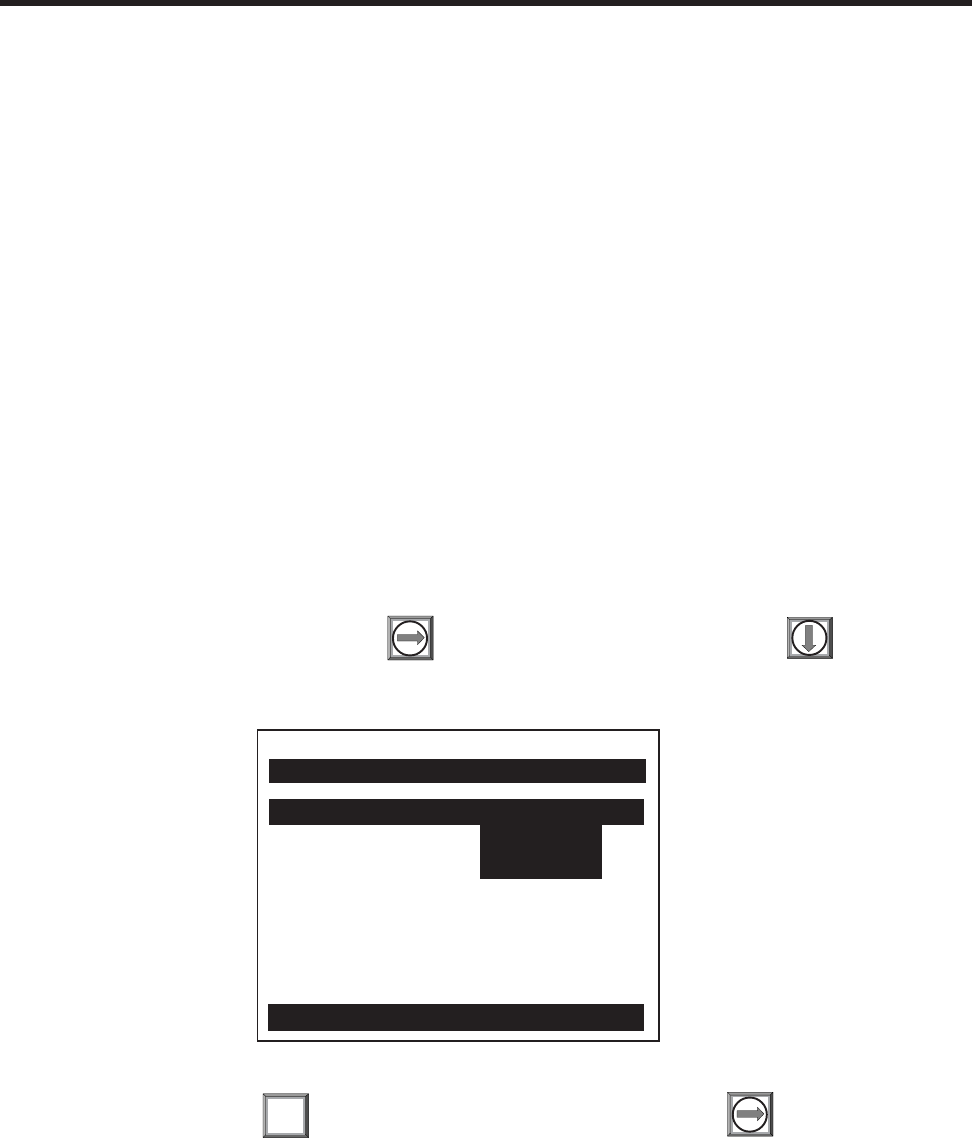
6-4
1010NFM-3JSection 6
6.3 HOW TO SET UP SYSTEM 1010 FOR FLOW TUBE OPERATION
The example in this section shows how to set up channel 1 of a 1010 dual channel system for use with
a 1011FT stainless steel Flow Tube. Note that Series 1010 dual-channel models allow flow tube opera-
tion with either measurement channel. In addition, all 1010 flow computers operate with both 1011FT
and 992DFT series of flow tubes. This example begins at the Channel Setup Menu. If necessary,
review paragraph 1.7.3 for instructions on how to select a Meter Type and a measurement channel.
6.3.1 OVERVIEW
Setting up the measurement channel for Flow Tube operation consists of the following tasks:
•Select a Meter Type (in this case Dual Channel Flow).
•Select a channel to install the flow tube (e.g., Channel 1).
•Set Kc calibration (slope correction) indicated on Flow Tube tag. (Note: Programmed Kc
must match offset error on plastic Kc tag to get accurate flow tube readings. See paragraph
2.7.3 Calibrate Flow Rate.)
•Create a site setup to store the flow tube installation parameters.
•Enter liquid Parameters (optional, default = water@68°F).
•Complete the Flow Tube install procedure.
6.3.2 SETUP PROCEDURE
From the Channel Select screen, press to access the option list, then press to move the
cursor to [FlowTube] (if required).
To select Flow Tube press . This enables the Flow Tube menu. Press to access Channel
Setup menu.
Channel 1 Clamp-on
Channel 2 >FlowTube
Reflexor
Siemens 2 Channel [1] Channel 1
Choose Channel 1 Flowmeter Type
Dual Channel Flow
ENT

6-5
1010NFM-3J
Section 6
Move the Highlight by pressing to [Create/Name Site]. To access the site name field
press . In this example, we will simultaneously create and name the site: FLOW1.
Use the character lists to select a site name as shown below.
To create a new site and register the site name press : FLOW1. Note that the name now appears
in the site name field on the upper right of the display and in the Save/Rename Site menu cell.
Press to leave the Channel Setup menu.
ENT
Siemens 2 Channel [1]
Recall Site Setup No Sites
Channel Enable No
Create/Name Site
Site SecurityFOff
Delete Site Setup No Sites
Save/Rename Site
Scroll saved Site Setup list and Enter
Channel Setup
Siemens 2 Channel [1]
Recall Site Setup No Sites
Channel Enable No
Create/Name Site ?FLOW1
Site SecurityFOff
Delete Site Setup No Sites
Save/Rename Site
Right Arrow & Enter Create a new Site
Channel Setup
Siemens 2 Channel [1] FLOW1
Recall Site Setup No Sites
Channel Enable No
Create/Name Site FLOW1
Site Security Off
Delete Site Setup No Sites
Save/Rename Site FLOW1
Use with Care -- Turn Security ON or Off
Channel Setup
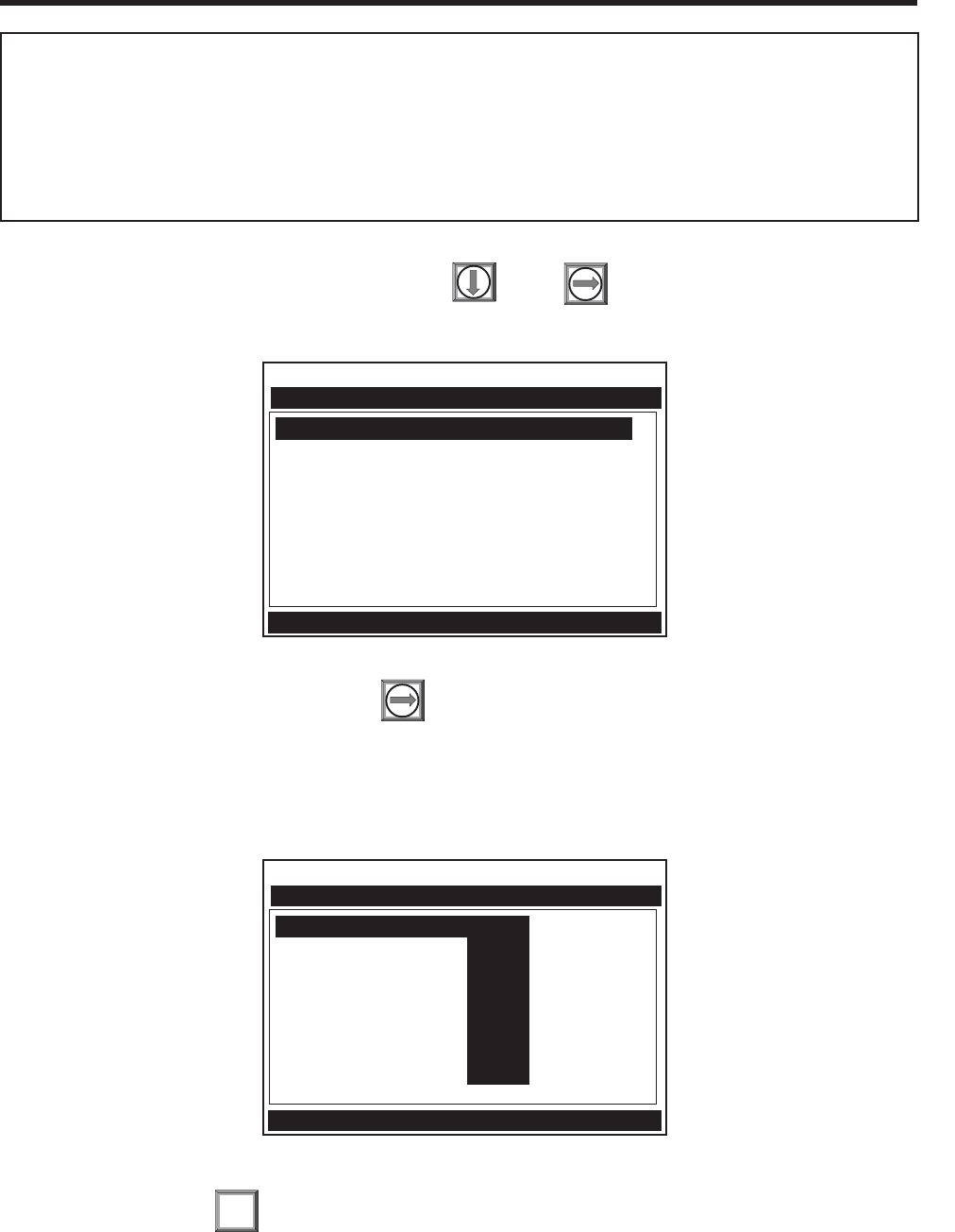
6-6
1010NFM-3JSection 6
To move the highlight to [Install Flow Tube] press . Press to access the Install Flow Tube
menu.
To access the Flow Tube option list press . Note that this list shows the currently available flow
tube sizes. The number is the size (e.g., 1). The letter represents the material (e.g., S = Steel, P =
PVC, T = Teflon, K = Kynar). In this example, we will install a size 1S Flow Tube. This 1011FTP-1S
(Stainless Steel) unit uses a 5/8” Swagelok Tube Fitting.
To select size 1S press . This moves the highlight to [Install Completed?].
ENT
Siemens 2 Channel [1] FLOW1
Select FlowTube 1S
Install Completed? No
Empty FlowTube Set Chan Not Setup
Zero Flow Adjust Chan Not Setup
Pick Flow Tube size and Type
Install FlowTube
Siemens 2 Channel [1] FLOW1
Select FlowTube >1S
Install Completed? 1P
Empty FlowTube Set 1K
Zero Flow Adjust 1T
2S
2P
2K
2T
Pick Flow Tube size and Type
Install FlowTube
Note that the next menu down is Liquid Data. This menu allows you to enter Viscosity (in centistokes)
and the Density (specific gravity) data for the liquid to be measured. Data entry in this menu is
optional. The default values are those of Water at 68°F (20°C). If you choose to edit these param-
eters, you should be aware that the viscosity of the liquid is an important factor. It governs the degree
of Reynolds Number compensation that the flow computer applies to the final rate output. Therefore,
flow data errors could result if you enter inaccurate data. Note that the Siemens Technical Service
Group may be able to provide the viscosity data for the liquid to be measured.
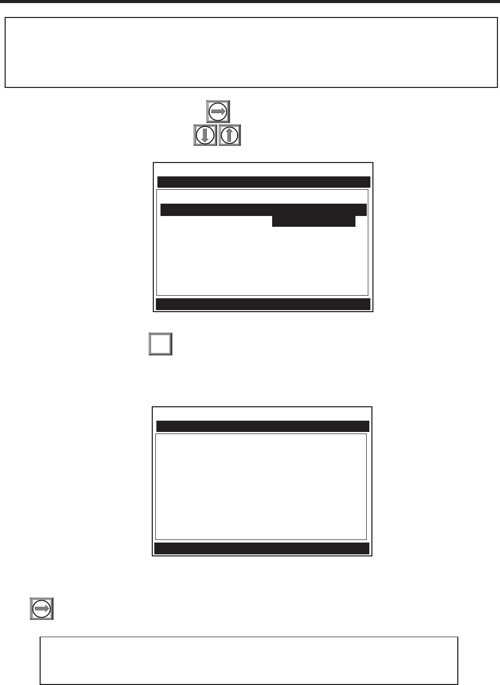
6-7
1010NFM-3J
Section 6
To invoke install routine press . This triggers Initial Makeup (an internal process that interrogates
the flow tube and analyzes setup data to optimize operation). During procedure, the meter shows its
progress by highlighting the prompt line.
Upon completion, the computer reports the measured sonic velocity. You can accept this reading or
press to adjust it (see field manual for instructions).
ENT
After filling the flow tube with liquid, press to access the [Install Completed?] option list and then
move the cursor to [Install] by pressing
Note that the default Empty Flow Tube Set is [MTYmatic]. The flow computer deter-
mines the empty flow tube setting automatically during the Initial Makeup, so use of
this menu cell is optional.
Siemens 2 Channel [1] FLOW1
Select FlowTube 1S
Install Completed? >Yes
Empty FlowTube Set New Makeup
Zero Flow Adjust Chan Not Setup
Key Install to start operation
Install FlowTube
Siemens 2 Channel [1] FLOW1
Select FlowTube 1S
Install Completed? Install
Empty FlowTube Set Chan Not Setup
Zero Flow Adjust Chan Not Setup
Drive 27 m 10 [6: :0]
Install FlowTube
You can complete the Installation procedure without actually mounting the flow tube at its intended location. Fill
the flow tube completely with liquid and connect the Up and DN cables according to the Installation/Outline
Drawing. Complete the instructions in this section. If you choose to mount the Flow Tube first, please conform
to the guidelines presented in this section and the Installation Drawing. In any case, do not proceed with these
instructions until the flow tube is filled completely with liquid.
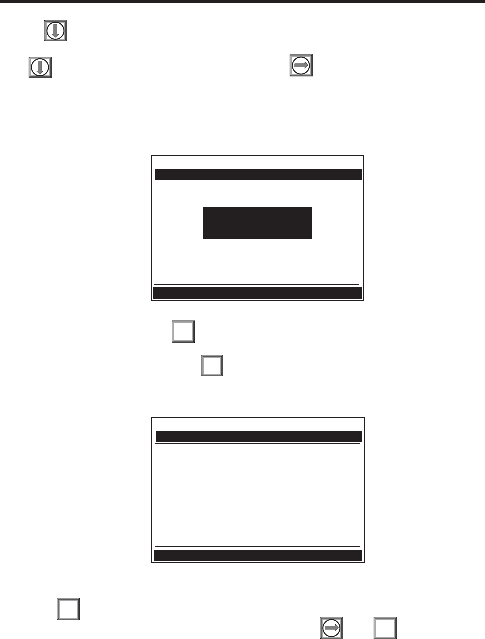
6-8
1010NFM-3JSection 6
Pressing accepts the displayed sonic velocity. This moves the highlight to [Empty Flow Tube
Set].
Press to move the highlight to [Zero Flow Adjust]. Press . This triggers the Zero Flow pop-up
window (see below). You can accept the default zero setting: [0.000] or enter a zero offset by typing it
with the numeric keys.
In either case, the flow through the Flow Tube MUST BE EQUAL TO ZERO FLOW OR YOUR DE-
SIRED OFFSET.
To start the zero acquisition routine . The highlighted prompt at top of the screen shows: [Inte-
grating “n” (n=counter)]. The integration period continues up a count of 60. You can stop the integra-
tion count at any time by simply pressing .
However, it is best to let the computer integrate the readings for the entire count.
When this routine is finished, the cursor moves to [Operation Adjust]. The flowmeter will be measuring
flow. Press to leave the menu.
A pop-up window prompts you to save the site. Do so by pressing , then . Provide a site
name, if desired (see paragraph 2.1.3). This moves you to the flow rate display screen. The flowme-
ter is now operational.
ENT
ENT
MENU
Siemens 2 Channel [1] FLOW1
Select FlowTube 1S
Install Completed? Yes
Empty FlowTube Set Chan No
Zero Flow Adjust Chan Not
Conforms Indicated flow to Actual zero
Install FlowTube
Zero Flow GAL/MIN
= 0.000
Siemens 2 Channel [1] FLOW1
Select FlowTube 1S
Install Completed? Yes
Empty FlowTube Set MTYmatic
Zero Flow Adjust Actual Zero
Integrating 9 Press [ENT]
Install FlowTube
ENT

6-9
1010NFM-3J
Section 6
6.5 SPECIFICATIONS – KYNAR PVDF FLOW TUBE
*Typical values, subject to change without notice.
6.4 SPECIFICATIONS – CPVC FLOW TUBE
*Typical values, subject to change without notice.
Pressure Drop 0.28 psi @ 1.5 GPM (5.7 LPM) 0.24 psi @ 4.5 GPM (17.0 LPM)
flowing water at 68°F flowing water at 68°F
Size 1 Size 2
Liquid Must be compatible with CPVC under Must be compatible with CPVC under
operating conditions and free of sus- operating conditions and free of sus-
pended gasses or solids. pended gasses or solids.
Sensitivity 0.0005 GPM (0.002 LPM) 0.0015 GPM (0.0057 LPM)
Linearity 1% of flow for rates above 0.09 GPM 1% of flow for rates above 0.27 GPM
(0.34 LPM) (1.0 LPM)
Repeatability ±0.2% of flow for rates above 0.6 GPM ±0.2% of flow for rates above 1.5 GPM
(2.3 LPM) (5.7 LPM)
Zero Stability ±0.0013 GPM (0.005 LPM) ±0.003 GPM (0.011 LPM)
Accuracy, ±1% of flow over 0.15 GPM (0.57 ±1% of flow over 0.5 GPM (1.9 LPM) to
Intrinsic LPM) to 5 GPM (20 LPM) 25 GPM (95 LPM)
Accuracy, Flow ±0.5% of flow over 0.15 GPM (0.5 ±0.5% of flow over 0.5 GPM (1.9 LPM)
Calibrated LPM) to 5 GPM (20 LPM) to 25 GPM (95 LPM)
Connection 3/8” FPT ¾” FPT
Repeatability ±0.2% of flow for rates above 0.6 ±0.2% of flow for rates above 1.5 GPM
GPM (2.3 LPM) (5.7 LPM)
Accuracy, ±1% of flow over 0.15 GPM (0.57 ±1% of flow over 0.5 GPM (1.9 LPM) to
LPM) to 5 GPM (20 LPM) 5 GPM (95 LPM)
Zero Stability ±0.0013 GPM (0.005 LPM) ±0.003 GPM (0.011 LPM)
Accuracy, Flow ±0.5% of flow over 0.15 GPM (0.57 ±0.5% of flow over 0.5 GPM (1.9 LPM)
LPM) to 5 GPM (20 LPM) to 25 GPM (95 LPM)
Size 1 Size 2
Liquid Must be compatible with PVDF Must be compatible with PVDF under
under operating conditions and free operating conditions and free of
of suspended gasses or solids. suspended gasses or solids.
Pressure Drop 0.28 psi @ 1.5 GPM (5.7 LPM) 0.24 psi @ 4.5 GPM (17.0 LPM)
flowing water at 68°F flowing water at 68°F
Sensitivity 0.0005 GPM (0.002 LPM) 0.0015 GPM (0.006 LPM)
Linearity 1% of flow for rates above 0.09 GPM 1% of flow for rates above 0.27 GPM
(0.34 LPM) (1.0 LPM)
Intrinsic
Calibrated
Connection 3/8” FPT 3/4” FPT

6-10
1010NFM-3JSection 6
Size 1 Size 2
Liquid Must be compatible with 316SS Must be compatible with 316SS under
under operating conditions and free operating conditions and free of sus-
of suspended gasses or solids. pended gasses or solids.
Pressure Drop 0.21 psi @ 1.6 GPM (6.0 LPM) 0.20 psi @ 4.5 GPM (17.0 LPM)
flowing water at 68°F flowing water at 68°F
Sensitivity 0.0005 GPM (0.002 LPM) 0.0015 GPM (0.0057 LPM)
Linearity 1% of flow for rates above 0.1 GPM 1% of flow for rates above 0.3 GPM
(0.38 LPM) (1.1 LPM)
Repeatability ±0.2% of flow for rates above 0.5 ±0.2% of flow for rates above 1.5
GPM (1.9 LPM) GPM (5.7 LPM)
Zero Stability ±0.001 GPM (0.0038 LPM) ±0.004 GPM (0.015 LPM)
Accuracy, ±1% of flow over 0.13 GPM (0.57 ±1% of flow over 0.4 GPM (1.5
Intrinsic LPM) to 10 GPM (40 LPM) LPM) to 30 GPM (114 LPM)
Accuracy, Flow ±0.5% of flow over 0.13 GPM (0.5 ±0.5% of flow over 0.4 GPM (1.5
Calibrated LPM) to 10 GPM (38 LPM) LPM) to 30(114 LPM)
Connection 5/8” Swagelok Tube Fitting 1” Swagelok Tube Fitting
6.7 SPECIFICATIONS – 316 STAINLESS STEEL FLOW TUBE
*Typical values, subject to change without notice
6.6 SPECIFICATIONS – TEFLON PFA FLOW TUBE
*Typical values, subject to change without notice
Liquid Must be compatible with PFA under Must be compatible with PFA under
operating conditions and free of sus- operating conditions and free of
pended gasses or solids. suspended gasses or solids.
Pressure Drop 0.23 psi @ 1.0 GPM (3.8 LPM) 0.23 psi @ 3.0 GPM (11.4 LPM)
flowing water at 68°F flowing water at 68°F
Sensitivity 0.0004 GPM (0.0015 LPM) 0.001 GPM (0.004 LPM)
Linearity 1% of flow for rates above 0.07 GPM 1% of flow for rates above 0.27 GPM
(0.26 LPM) (1.00 LPM)
Repeatability ±0.2% of flow for rates above 0.6 ±0.2% of flow for rates above 1.5 GPM
GPM (2.3 LPM) (5.7 LPM)
Zero Stability ±0.001 GPM (0.0038 LPM) ±0.003 GPM (0.012 LPM)
Accuracy, ±1% of flow over 0.15 GPM (0.57 ±1% of flow over 0.5 GPM (1.9 LPM) to
Intrinsic LPM) to 5 GPM (20 LPM) 16 GPM (60 LPM)
Accuracy, Flow ±0.5% of flow over 0.15 GPM (0.57 ±0.5% of flow over 0.5 GPM (1.9 LPM)
Calibrated LPM) to 5 GPM (20 LPM) to 16 GPM (60 LPM)
Connection 1/2” Flaretek Ultrapure PFA Tube 3/4” Flaretek Ultrapure PFA Tube
Fitting Fitting
Size 1 Size 2

6-11
1010NFM-3J
Section 6
ADDITIONAL INSTALLATION NOTES
zAll Siemens Flow Tubes are supplied with integral line connections. The end-user must supply any
adapters, etc. required for line connection.
zWhen connecting a screwed fitting to a Kynar, Teflon (PFA) or CPVC Flow Tube, please start the
thread carefully to avoid cross threading. Hand-tighten only. If necessary, use Teflon tape manufac-
tured for plastic piping to effect a leak-proof seal (see Appendix C- Engineering Drawings for de-
tails).
zWhenever possible, use the mounting brackets to support the weight of the flow tube.
zConsult the supplied engineering drawing for important dimensional data.
Flow Direction
Indicator
Mounting
Bracket
OUTLET
(Use Swagelok
Tube Fitting)
INLET
(Use Swagelok
Tube Fitting)
1011FT Series 316 Stainless Steel Flow Tube
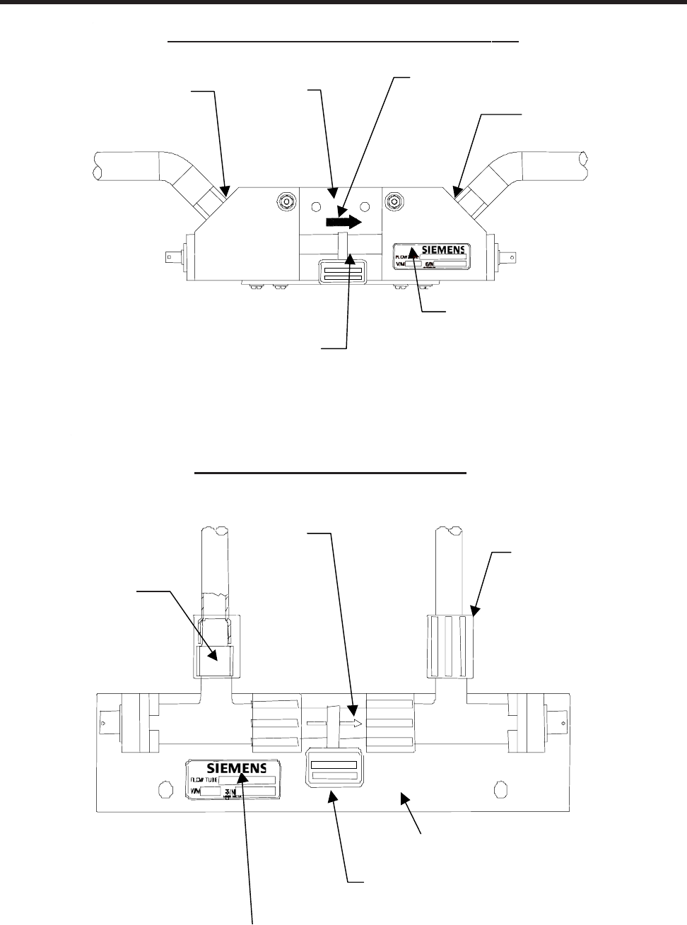
6-12
1010NFM-3JSection 6
Model
Identification
Flow
Direction
Indicator
Calibration factor (valid for
indicated flow direction
only)
Inlet
(FPT) Outlet
(FPT)
992DFT Series CPVC or
K
ynar PDFA Flow Tube
Mounting
Bracket
992DFT Series CPVC or Kynar PDFA Flow Tube
992DFT Series Teflon PFA Flow Tube
INLET
(Use
Flaretek®
Tube Fitting)
Flow
Direction
Indicator
OUTLET
(Use
Flaretek®
Tube Fitting)
Calibration factor (valid
for indicated flow
direction only)
Model Identification
Mounting Bracket
992DFT Series Teflon PFA Flow Tube
Tube Fitting)

7-1
1010NFM-3J
Section 7
7. THE SYSTEM 1010 REFLEXOR FLOWMETER
Reflexor is one of the operating modes available on certain 1010 models. The Reflexor operating mode
utilizes Doppler flow detection along with digital signal processing techniques to successfully measure
flow under conditions that may not be suitable for transit-time flow measurement. The Reflexor samples
the flow stream as it detects Doppler shift. It converts the Doppler shift information by use of Fast
Fourier Transform (FFT) and filters the FFT to determine the flow rate. The Reflexor mode will operate
with many of the same transducers that are used with transit-time flow measurement along with those
which are specifically designed for Doppler flow measurement. Use of any other transducer than
shown in these instructions may result in failure to measure or give an incorrect flow rate indication.
7.1 REFLEXOR INSTALLATION STEPS
The typical steps to complete the installation procedure are as follows:
•Collect the site data (pipe and liquid data, part numbers, etc.).
•Choose a mounting location for the flow transducers.
•Prepare the pipe for transducer’s mounting.
•Access the Installation Menu and create a site.
•Enter the pipe parameters.
•Mount flow transducers on pipe and connect to flow meter.
•Invoke the transducer installation procedure.
•Optimize installation through use of the Spectra Display and diagnostic data.
Please do not allow the size of the Installation Menu to intimidate you. Almost all menu cells will contain
default parameters and will not require any additional action. To obtain operation you will only need to
access the menu cells for required parameters, such as pipe data. Obtaining accurate flow rate data
will take less than five minutes.
Application conditions may require you to mount the transducers using the adjacent mounting method
as described and shown in paragraph 7.4.
7.2 SELECT A TRANSDUCER SET FOR USE BY REFLEXOR
The transducer recommended for use by Reflexor is any of the currently available Spectra transduc-
ers. For general purpose dedicated use, this is the 191N1S transducer set. Alternate transducers are
any of the 1011 size C Universal, 991 size 2 and 3A including High and Very High Temperature versions
along with the 1011 High Precision size A3 and B1. The maximum sensitivity will be obtained with use
of the 191N1S transducers. Transducer models are available for submersible and extended tempera-
ture applications.
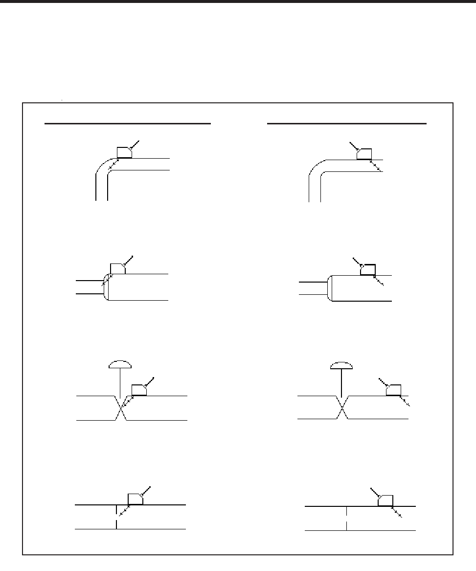
7-2
1010NFM-3JSection 7
7.3 SELECT THE TRANSDUCER MOUNTING LOCATION
Select a mounting location that has a fully developed flow profile. Do not locate the transducer so that
sonic energy enters a region that is not representative of the flow velocities at the measuring location.
Use the figure below as a guide to select the proper mounting location.
Incorrect Transducer Placement Correct Transducer Placement
ELBOW
EXPANSION
OR
CONTRACTION
VALVE
ORIFICE PLATE
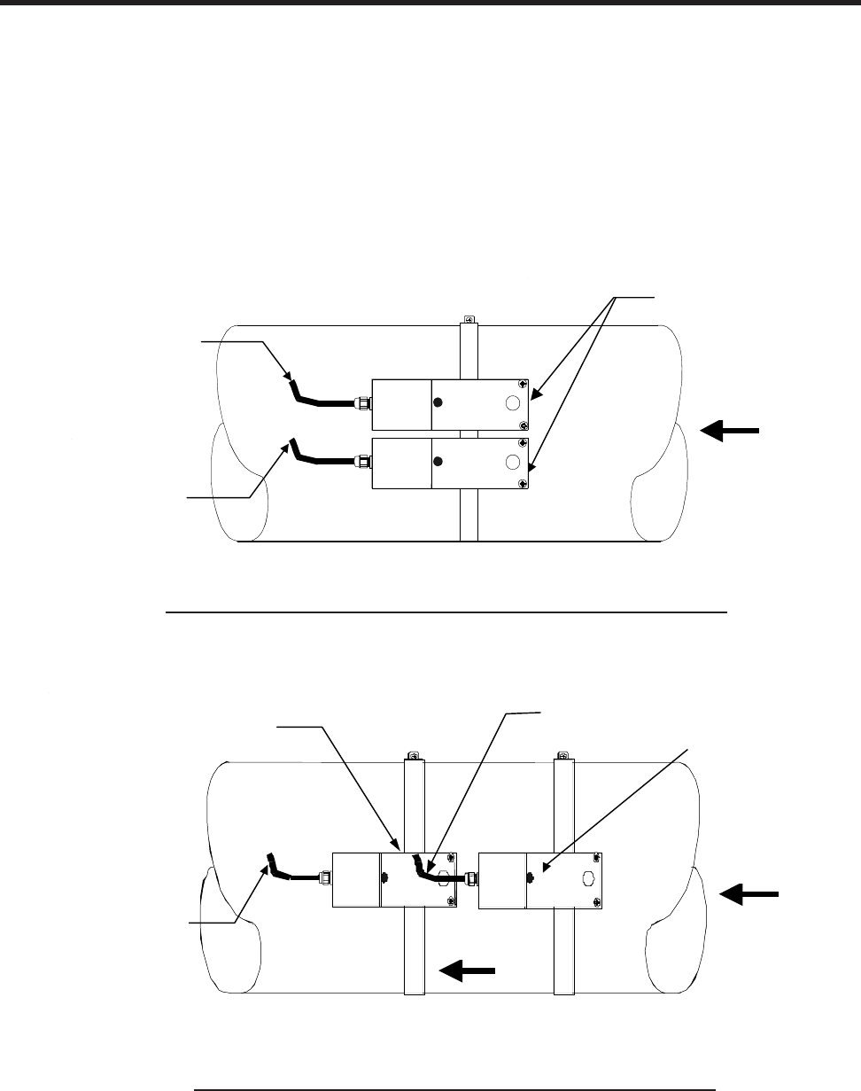
7-3
1010NFM-3J
Section 7
7.4 MOUNTING THE TRANSDUCERS
Two mounting configurations are available. Adjacent mounting locates the two transducers alongside
each other using a single mounting chain or strap. In-Line mounting locates the two transducers axially
along the pipe using two mounting chains or straps. On metal pipes the Receive Transducer is always
located behind the Transmit Transducer. On plastic pipes the Transmit Transducer is always located
behind the Receive Transducer. In both cases, the cable entry will be on the same end of both trans-
ducers unlike the transit-time configurations. Adjacent mounting will provide the maximum sensitivity to
flow. Refer to the appropriate transducer installation drawing for the 191N1S (Installation Drawing
191N1S-7).
REFLEXOR MODE - ADJACENT TRANSDUCER MOUNTING
Connect to
DOWN terminal
on flow computer
Connect to UP
terminal on flow
computer
Flow Direction
“C2”
Transducers
Connect to UP
Terminal on flow
computer
Connect to DOWN
Terminal on flow
computer
C2 Transducers
Flow Direction
REFLEXOR MODE - IN-LINE TRANSDUCER MOUNTING
Connect to DOWN
terminal on flow
computer
(Receive)
“C2” Transducers
Connect to UP terminal on
flow computer (Transmit)
Flow Direction
Flow Direction
“C2”
Transducers
NOTE: Transducer position shown is for metal pipes.
C2 Transducers
Connect to
DOWN Terminal
on flow computer
(RECEIVE) Flow Direction
Flow Direction
C2 Transducers
Connect to UP Terminal on
flow computer (TRANSMIT)

7-4
1010NFM-3JSection 7
Channel 1 Clamp-on
Channel 2 >Reflexor
Siemens 2 Channel [1] Channel 1
Choose Channel 1 Flowmeter Type
Dual Channel Flow
7.5 CONNECTION OF TRANSDUCER CABLES
Connect transducer cables between the transducers and the flow computer. The XMIT (transmit)
transducer is connected to the Up cable connection and RCV (receive) transducer is connected to the
Down cable connection. The correct connection orientation is important for the in-line transducer con-
figuration. It is not a factor for the adjacent configuration.
7.6 SELECT REFLEXOR OPERATING MODE
Select meter type as Reflexor for the channel that is to be used as Reflexor. Dual channel units may
have either one or both channels used in the Reflexor mode.
7.7 INSTALLING REFLEXOR OPERATING MODE
Access [Channel Setup] and “Create or Recall” a previous Saved Site setup. If a previous Saved Site
is recalled, and the same transducer and location is used, then no other installation steps are required.
Access [Pipe Data] and enter the required pipe data.
7.8 ACCESS THE INSTALL XDCR (TRANSDUCER) MENU
At [Transducer Model], press the <Right Arrow> and select the proper group of transducers that match
the mounted transducer set. For all 191N, select 190.
At [Transducers Size], select the proper size of transducer mounted. For all 191N, select 191.
If the flow rate units are not the default units of Gallons per Minute, then it is recommended to change
those units now by use of the Flow/Total Units menu.
At [Flow Range], press the <Right Arrow> and select the lowest flow range rate that is at least two
times higher than the maximum flow expected at this application.
At [Install Completed?], for new installations, press the <Right Arrow>, select [Install], and then select
[Yes]. Press the <ENT> key.
The meter is now operational and the display will show flow by pressing the <MENU> key.
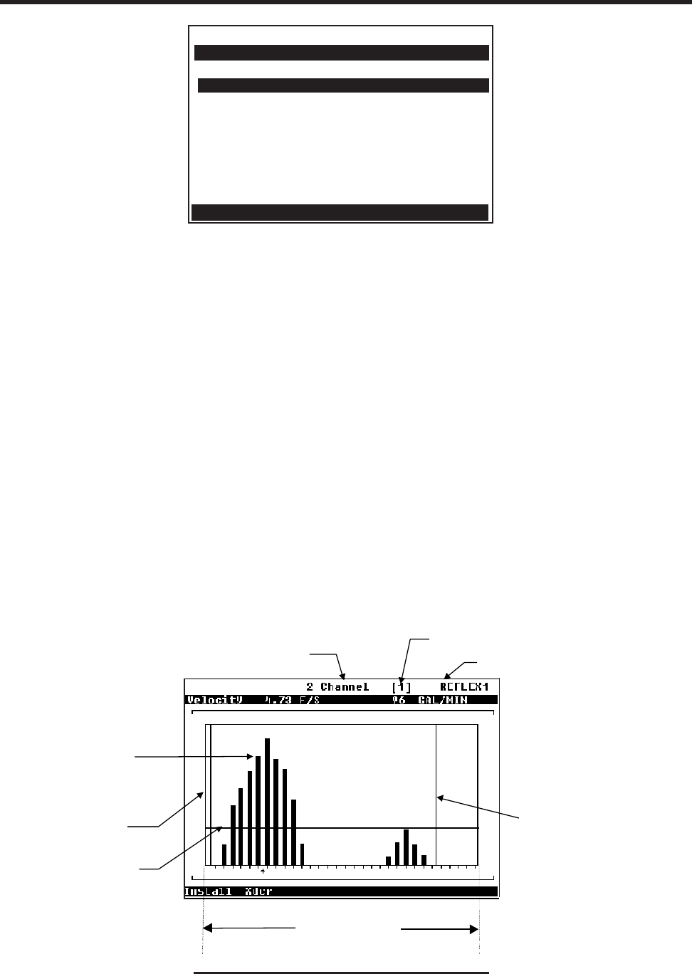
7-5
1010NFM-3J
Section 7
Siemens 2 Channel [1] Channel 1
Key Install to start flow measurement
Install Xdcr
Transducer Model 190
Transducer Size 191
Flow Range GAL/MIN 6.71
Install Completed? Yes
Spectra Graph No
7.9 THE SPECTRA DISPLAY SCREEN
The Spectra Graph provides a powerful tool to determine if the installation has achieved an adequate
margin of operation. It also eliminates the possible effects of mechanical vibration and external RFI
(Radio Frequency Interference). Mechanical vibration and external RFI can cause other types of Dop-
pler flowmeters to be inaccurate. The Spectra Graph screen provides keypad control keys that allow
adjustments of application dependent parameters, if required, while observing the results of these
adjustments. Application dependent parameters are the Low and High Limit Cursors and the Noise
Cursor. In most cases, only the Noise Cursor will be required to be adjusted.
To display the Spectra Graph, position the highlight over Spectra Graph and use the <Right and Down
Arrows> to select [Yes].
The Spectra Graph display shows the results of the Fast Fourier Transform (FFT) performed by the
flow computer. The horizontal scale represents flow velocity with the higher velocities on the right and
lower velocities on the left. The vertical axis is relative amplitude or magnitude; each bar shows the
relative amplitude for a velocity range. The reported flow rate is the mean value of the included Spectra
Graph bars. It is computed by excluding signals that are lower (to the left of) than the Low Limit Cursor
or higher (to the right of) than the High Flow Cursor or lower (under) than the Noise Cursor.
EXAMPLE OF A SPECTRA DISPLAY SCREEN
Meter Type
Measurement
Channel Site name
High Limit
Cursor
Flow Velocity Range
N
oise Level
Set Cursor
Low
Limit
Cursor
Signal
Amplitude
Siemens
Meter Type
Signal
Amplitude
Measurement
Channel
Site Name
High Limit
Cursor
Flow Velocity Range
Low Limit
Cursor
Noise Level
Set Cursor

7-6
1010NFM-3JSection 7
7.10 CURSOR USE ON THE SPECTRA GRAPH
7.11 HOW TO USE SPECTRA GRAPH DATA AND CONTROLS
When you first access the Spectra Graph, the data shown on the top highlighted line shows Velocity in
feet-per-second (F/S) on the left side and the volumetric Flow Rate in the current rate units on the right
side. You can scroll the data shown using the <Up and Down> Arrows.
Pressing the <Up Arrow> changes the data in the highlight to [Diagnostic Data] containing, from left to
right: (Hz) Doppler shift frequency in Hertz, (mV) Signal Amplitude in millivolts, (FFT Pk) Peak FFT
magnitude and (%D) FFT Percent Deviation. Carefully inspect the data for Signal Amplitude and Per-
cent Deviation. Refer to the “Available Adjustments to Spectra Graph” table in paragraph 7.12 and the
“Reflexor Diagnostic Data” table found in paragraph 7.13. Press the <Down Arrow> to return to Veloc-
ity.
Press the <Down Arrow> from Flow Velocity in feet per second (F/S) to advance to the Noise Level Set
cursor control. A numeric indication of the Noise Level Cursor position is provided in the highlighted
area. Refer to the “Available Adjustments To Spectra Graph” table found in paragraph 7.12.
Adjust the Noise Level cursor, if required, by pressing the <+> key to increase or <-> key to decrease.
NOTE: A delay in response to all keys will occur. This is due to the longer periodic sampling of
the keyboard by the processor while performing FFT’s.
Press the <Down Arrow> from Noise Level to advance to the High Limit cursor control. The <+> and
<-> key are active in this position. Refer to the “Available Adjustments To Spectra Graph” table found in
paragraph 7.12.
CURSOR USAGE TIPS
High Limit Cursor This cursor appears as a vertical line on the right side of the Spectra
Graph. All signals to the right of this line will be excluded from the flow
calculation. Use this adjustment if the right side of the Spectra Graph
has noise that is larger in amplitude than the signal that is produced by
flow. The cursor may be arbitrarily placed at two times the maximum
flow expected.
Low Limit Cursor This cursor appears as a vertical line on the left side of the Spectra
Graph. All signals to the left of this line will be excluded from the flow
calculation. Use this adjustment if the left side of the Spectra Graph
has noise that is larger in amplitude than the signal that is produced by
flow. The cursor may be arbitrarily placed at one half the minimum flow
expected.
Noise Level Set Cursor This cursor appears as a horizontal line on the Spectra Graph. All sig-
nals below this line will be excluded from the flow calculation. Position
the cursor approximately one quarter the height of the FFT peak.

7-7
1010NFM-3J
Section 7
Press the <Down Arrow> from High Limit to advance to the Low Limit cursor control. The <+> and
<-> keys are active in this position. Refer to the “Available Adjustments To Spectra Graph” table
found in paragraph 7.12.
Press the <Down Arrow> from Low Limit to advance to the Carrier FX control. The <+> and <->
keys are active in this position.
Press the <Down Arrow> from Carrier FX to advance to the Diagnostic Data Display. The <+> and
<-> keys are active in this position.
To exit the Spectra Graph, press the <Menu> key.
To display the Digital Flow Display, press the <Menu> key from any Installation Menu location.
7.12 AVAILABLE ADJUSTMENTS TO SPECTRA GRAPH
The table below describes the available adjustments that can be made to the Spectra Graph.
ADJUSTMENT FUNCTION NOTE
Noise Level Set Noise Filter Set to approximately one quarter the Peak
FFT value for typical flow conditions.
High Limit Low Pass Filter Setting Set to two times the maximum flow rate.
Low Limit High Pass Filter Set to one half minimum flow if noise is
present. In most cases, leave at zero.
Carrier Fx Transmit Frequency
Code Adjust only under guidance of technical sup-
port staff.

7-8
1010NFM-3JSection 7
7.13 REFLEXOR DIAGNOSTIC DATA
The Diagnostic Data menu screen provides one location where all diagnostic data can be viewed.
Please note, adjustments can not be made on this screen. Adjustments can only be made on the
Spectra Graph.
DIAGNOSTIC DATA
APPLICATION INFORMATION FUNCTION / EXPLANATION
Low Limit High Pass Filter Setting
% Deviation The width of Spectra is used to determine beam
penetration and calibration. The selection of
“Slurry” in Application Data is recommended for
flow rate indication accuracy when the % Devia-
tion is less than 25. For % Deviation above 35
the use of “Liquid” is recommended.
For applications that continuously have % De-
viation between 25 and 35 proper selection of ei-
ther Liquid or Slurry can be confirmed by com-
parison to a known flow reference.
High Limit Low Pass Filter Setting
Noise Level Set Noise Filter Setting
Doppler Frequency (Hz) Average FFT Frequency
Signal Peak-to-Peak mV Peak-to-Peak demodulation signal amplitude.
The acceptable range is between 100 and 3200
mV during typical flow conditions. If less than 100
mV, check transducer type used and mounting
configuration. If greater than 3200 mV, try in-line
mounting and/or “detune” Carrier Fx.
FFT s/sec Number of FFTs per second
FFT Peak Peak FFT Amplitude
Carrier Fx Transmit Frequency code

7-9
1010NFM-3J
Section 7
Siemens 2 Channel [1] Channel 1
Shows range of flow rates detected
Application Info
Low Limit GAL/MIN 0.00
High Limit GAL/MIN 16.75
Noise Level Set 2
Doppler Freq <Hz> 8571
% Deviation > 100.00
Signal Pk-Pk mV 27
FFTs/Sec 28
FFT Peak 0
Carrier fx <drive> 27
7.14 DISPLAY OF “F” AT NO FLOW CONDITIONS
It is normal for the digital display to show an “F” for the no flow condition since the lack of Spectra
information during no flow is the same as a fault condition.
NOTE: Selecting the Operation Adjust menu cell [Zero/Fault Set] allows the option of indicating
Zero Flow rather than a Fault (see paragraph 2.5.4 for details).
7.15 SELECTION OF LIQUID COMPOSITION
The width of the Spectra wave shape is an indication of the depth of penetration of sonic energy into the
flow stream. The % Deviation is a measure of the width of the Spectra and is representative of the
penetration of the sonic beam into the liquid. Select [Slurry] in the Application Data menu for better flow
rate indication accuracy when the % Deviation is less than 25 with typical flow conditions. For % Devia-
tions above 35, select [Liquid]. For applications that continuously have % Deviations between 25 and
35, proper selection of either [Liquid] or [Slurry] can be confirmed by comparison to a known flow
reference.
7.16 OTHER MENU ENTRIES
All other menu entries will operate and be used in the same manner as the transit time flow measure-
ment mode.
Siemens 2 Channel [1] Channel 1
Choose Liquid or Slurry flow calibration
Application Data
Liquid Composition Liquid
Density SG 1.00

APPENDIX A
Couplant
Installation
Instructions
FOR TECHNICAL ASSISTANCE
Call: (800) 275-8480
(631) 231-3600
Fax: (631) 231-3334
E-mail: TSG.ultrasonicflow@siemens.com
FOR GENERAL INFORMATION
Website: www.controlotron.com
E-mail: info.ultrasonicflow@siemens.com
Or: sales.ultrasonicflow@siemens.com
Copyright©2006 Siemens Energy & Automation, Inc. All Rights Reserved Made in the USA

NOTE
Currently there are no Couplant Installation Instructions
included in this field manual for this unit.
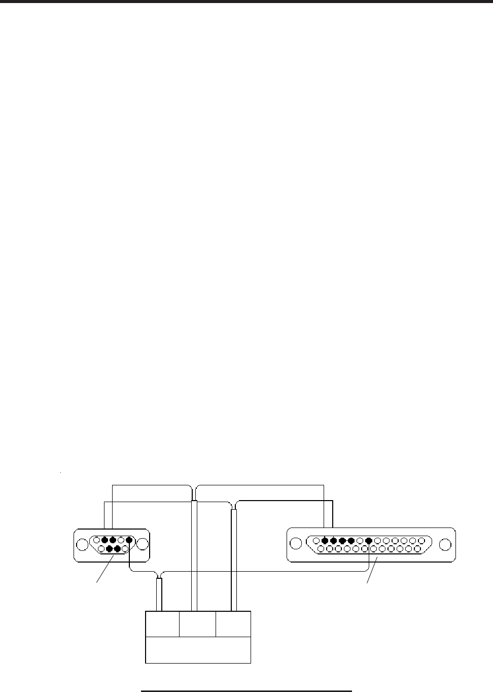
B-1
1010NFM-3J
Appendix
SITE SETUP CONSIDERATIONS FOR 1010/1020N BLIND SYSTEMS
Siemens offers an economical “blind” 1010/1020 NEMA system (without a local keypad and graphic
display screen). This supplement describes the hardware and software requirements for program-
ming these models. Site setup for a blind unit requires a PC connected to the RS-232 serial port.
These models include a serial interface cable for this purpose. The serial interface cable includes 9-
pin and 25-pin connectors to accommodate both types of IBM-compatible serial ports. A PC commu-
nication program such as Terminal (Windows 3.x) or HyperTerminal (Windows 95/98/NT/2000/XP)
serves as the data entry interface. These programs reproduce the menu screens that would appear on
the system’s graphic screen. In fact, the example screens in this manual are actual HyperTerminal
screen captures. Once the serial interface is established, the site setup procedure for blind and graphic
display systems are identical. You could choose to program a graphic display system using a PC and
a communications program. However, note that for models with a local display screen, the serial
interface cable is an option.
NOTE: You can use a DOS-based communications program also. Make sure that your PC is
loading the ANSI.SYS driver via your Config.sys file. Set the program’s RS-232 param-
eters to match those of the flowmeter (see HyperTerminal example screen on the fol-
lowing pages).
NOTE: Many newer Laptop PC’s are not equipped with serial ports, having USB ports only.
These PC’s will require a USB RS-232 adaptor that can be purchased commercially. Not
all of these adaptors are suitable. Siemens has found the best performance is achieved
with the adaptor from Radio Shack, (Part# 26-183).
THE RS-232 INTERFACE CABLE
The physical connection between the flow computer and your PC is accomplished using a serial
interface cable, part number: 1015CPC-N. The schematic below shows the configuration of the cable.
The wire ends for the flow computer termination are tinned for easy insertion into TB1 on the flow
computer. Each wire is labeled to identify the correct terminal pin on TB1. In addition, both connectors
have their CTS pin shorted to the RTS pin (pins 4 - 5 on 25-pin connector and pins 7 - 8 on 9-pin
connector). This eliminates the need for hardware “handshaking.”
APPENDIX B
1015CPC-N SERIAL INTERFACE CABLE
6
GND
4
RX
1
TX
TB1
*Solder side shown
*Solder side shown
2 3 5
7 8
2 3 4 5 7

B-2
1010NFM-3J
Appendix
Due to the different System 1010/1020 meter configurations, there are 3 types of RS-232 communica-
tion cables employed. You can determine which cable is required for the your model flowmeter from
the table below. Be sure you have the appropriate cable available for use.
For those who would prefer to make the cables themselves, the required parts (except for the
RS-232 connector for the 1010WP meter types) should be available at most computer or electronics
stores. You will find drawings of the terminations for these cables with the reference table below.
It provides the signal names, PC termination and 1010/1020 meter termination for each type of
flowmeter.
Also, in most computer stores or online, you will be able to find or you may already have a serial
“LapLink” cable or “Null Modem” cable. These cables can be used to communicate with the 1010P/
DP and 1020N systems.
If you purchased a 1010W model, you may have received the special connector used for the RS-
232 terminal in a packet included with your 1010W. This will enable you to construct the appropriate
cable for this meter type.
If you prefer to construct your own cable, the following conventions apply in the table:
PC: Refers to an IBM compatible, DB-9 serial Com port.
1010N: Includes all models (N, DN, MN, E, EXCEPT those with “A1” option). Termination is made
to the 1010N-2 I/O Data Module. Flowmeter end of cable is unterminated wire.
1010N With “A1” Option: Meters that carry ”A1” option have 1010N-7 module installed that
houses a DB-9 connector for RS-232 communication.
1010P/1020N: Includes all models (P/DP). Termination is made to the RS-232 port DB-9 connector.
A DB-9 Female connector is needed to mate with the meter connector.
1010WP: Includes all models (WP, WDP except energy meters). Termination is made to the RS-
232 port on the connector panel. A special cable terminal is required and can be obtained from
Controlotron (Part #1015XWP).
1010X: Includes all models (X, DX). Termination is made to the 1010X-8 I/O module Terminal
TB2. Flowmeter end of cable is unterminated wire.
Meter Type Cable Type Controlotron Part Number Notes
Weatherproof Portable DB-9F – Amphenol 1015CPC-WP Except Energy
1010P/1020N DB-9F – DB-9F 1015CPC-P Use for Energy WP
All NEMA4X DB-9F – 3 Wire 1015CPC-N
NEMA 4X with Expanded DB-9F - DB-9F 1015CPC-P For 1010N with “A1”
I/O Module option (1010N-7 module)
All 1010X DB-9F – 3 Wire 1015CPC-N

B-3
1010NFM-3J
Appendix
Signal PC DB-9 1010P/1020N 1010WP 1010N 1010X
Name Terminal Terminal Terminal Terminal Terminal
Ground Pin 5 Pin 5 Pin E TB1- pin 6 TB2-pin 16
Tx Pin 2 Pin 3 Pin C TB1- pin 1 TB2-pin 11
Rx Pin 3 Pin 2 Pin B TB1- pin 4 TB2-pin 14
HOW TO USE THE Windows HyperTerminal PROGRAM
Windows provides a communication program called HyperTerminal, which is ideal for interfacing your
computer with the flowmeter. The following typical example explains how to set up HyperTerminal.
NOTE: Depending upon the Windows applications being used this setup procedure may vary.
1. From the Windows desktop, left-click on the [START] button.
2. Holding down the left mouse button, move the highlight up to [Programs], then across to [Accesso-
ries]. Slide the highlight down to [HyperTerminal], then release the left mouse button.
3. Within the HyperTerminal window, move the mouse pointer down to [Hyperterm.exe] and then
double-click the left mouse button.
4. This selects the [Connection Description] dialog box. Enter a name for your connection (e.g.,
1010N). You can optionally select an icon for this connection by clicking on one of the icons
displayed in the scrolling frame at the bottom of the window. Click [OK].
5. This selects the [Phone Number] dialog box. Move the cursor to the arrow at the right of the
[Connect Using] field. Left click on the arrow to expand the field and then move the highlight down
to [Direct to Com 1 (or 2)] depending on the port connected to the interface cable. Click [OK] to
select the [Com 1 (or 2) Properties] Dialog box. Set up your RS-232 parameters as shown in the
example below. Left-click on the [OK] button.
COMMUNICATING WITH SYSTEM 1010/1020 VIA THE RS-232 INTERFACE
The following sections assume that you are familiar with the basics of using a Windows 3.x or Win-
dows 95/98/NT/2000/XP based communications program. All PC computers provide at least one se-
rial port using either a 9-pin or 25-pin D-type connector. The port designation can be either COM 1 or
COM 2. Usually, when a computer includes two serial ports, COM 1 will be the 9-pin connector and
COM 2 will be the 25-pin connector. However, port designations can vary from manufacturer to manu-
facturer, so you will have to positively identify the COM port you wish to use for the flowmeter interface.
Connect the cable between the flowmeter and your PC using either the 25-pin, 9-pin or USB to RS-
232 adapter connector, depending upon the port’s architecture.
15
69
PC DB
-9 Connector
1010P/1020N/990P Connector
(Wiring Side View)
H AB
GK JC
F ED
1010WP/WDP Connector
(Wiring Side View)
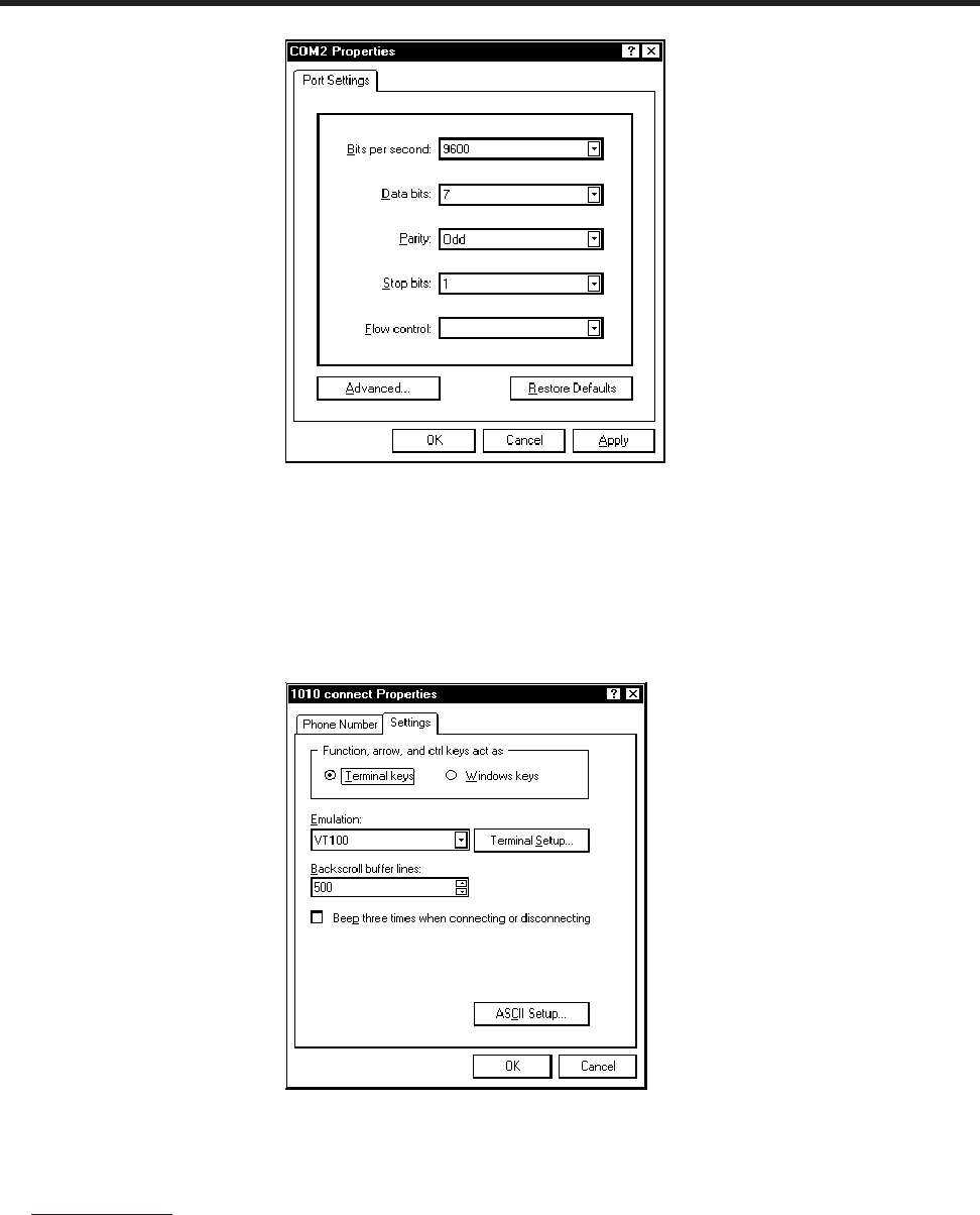
B-4
1010NFM-3J
Appendix
6. You will now see a blank terminal screen. Next left-click [File] on the top menu bar. Drag the
highlight down to [Properties] and then left-click.
7. Left-click the [Settings] tab. Expand the [Emulation] box by left-clicking the <Down Arrow> on the
right-hand side. Drag the highlight down to [VT-100] and then left-click to select it (as shown
below).
8. Next, left-click on the [ASCII Setup] button (see screen above). In the [ASCII Sending] dialog box,
make sure that both [send line ends with line feeds] and [Echo Typed characters locally] are
UNCHECKED. In the [ASCII Receiving] dialog box, left-click to place a check mark before the
[Append line feeds to incoming line ends] dialog. When your screen looks like the example below,
left-click the [OK] button.
None

B-5
1010NFM-3J
Appendix
9. You are now ready to communicate with the 1010 flowmeter. But first, save your settings by mov-
ing the mouse cursor to [File], sliding the cursor to [Save], then clicking [OK] on the Save dialog
box.
10. The next time you want to use HyperTerminal:
Click on Start.
Drag to Programs.
Drag to Accessories. Drag to HyperTerminal, and click.
Double-click the icon you selected for the connection.
NOTE: For easier access, create a shortcut to the connect icon from your desktop. Right-click
on the icon to open its dialog box. Left-click on [Copy] or [Create a Short Cut] and then
move the mouse cursor to a blank area on your desktop. Right-click to open dialog box
and then left-click on [Paste] to place a shortcut to the connect icon on your desktop.
Accessing the Installation Menu
Once the parameters are set, HyperTerminal automatically initiates Command mode. You will see a
blank screen.
Press <ENT> a few times until you see [? For Help] on the screen.
Type: ? (question mark) and then press <ENT> to see a list of the available commands.
Use the MENU command (type [Menu] and then press <ENT>) to access the top level of the Installa-
tion Menu. You will see a screen similar to the example below.
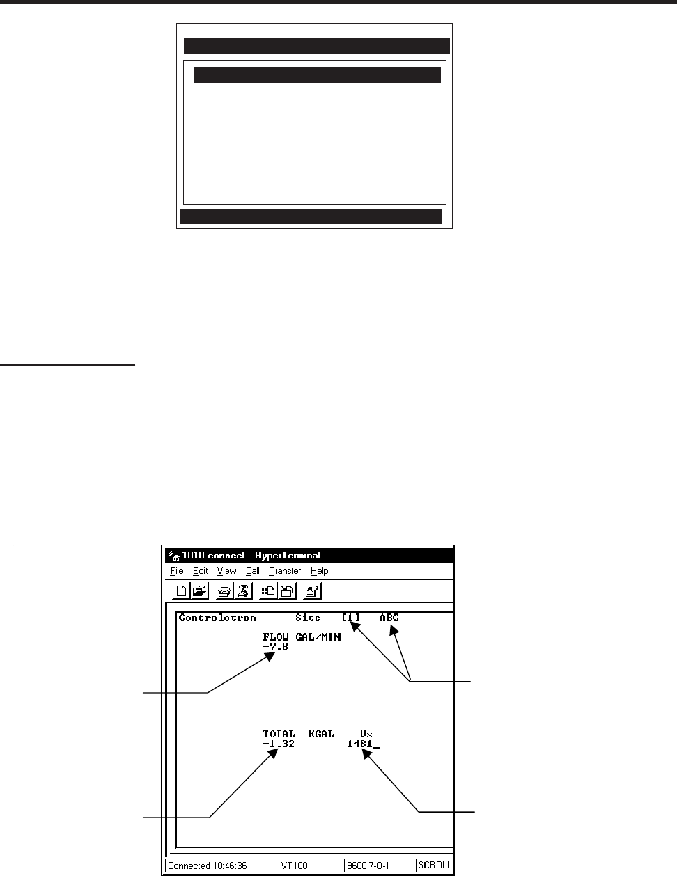
B-6
1010NFM-3J
Appendix
Data Display Mode
After you complete the installation, you can toggle between Installation Menu mode to Data Display
mode. This is the same as using the <MENU> key on the 1010 keypad (see manual). The PC key-
board equivalent to the <MENU> key is <CNTRL> + <L>. Note that the 1010 RS-232 interface does
not support graphics. Therefore, when you use HyperTerminal to view the data display screens, you
will see the same data in alphanumeric form only (as shown below). You can still use the <Up Arrow>
and <Down Arrow> to switch between available display screens.
NOTE: To facilitate connecting through modems, the [Menu] command times out after three
minutes of inactivity. To maintain a longer connection type: Menu 1000 and press <ENT>.
The optional number is the amount in minutes that the connection will be maintained.
Typing [Menu 1000] essentially keeps the interface alive until you cancel it.
Siemens Site [1]
Select Meter Type
Meter Facilities
Meter Type Single Channel
This is the current flow
reading and flow units.
(This would be a large
graphic characters on
the1010 screen.
This is the current measured liquid
sonic velocity (Vs).
This is the flow
total display.
This is the name of the current active
site setup. The [1] indicates that
measurement channel is currently
active.
This is the current flow
reading and flow units.
(This would be a large
graphic character on
the 1010 screen
This is the flow
Total display
This is the current measured liquid
sonic velocity (Vs).
This is the name of the current active
site setup. The [1] indicates that the
measurement channel is currently
active.

B-7
1010NFM-3J
Appendix
Navigating Through the Installation Menu
After accessing the Installation Menu, you can begin to setup your flowmeter according to the instruc-
tions in this manual. The chart below shows the PC keyboard equivalents to the 1010 keypad keys
while you are in the menu.
Terminal Mode Menu Commands
In addition to Menu, the following commands (followed by the <ENT> key) can be used to control the
flowmeter while in Terminal Mode.
Note that “n” refers to the flowmeter Channel number. For a dual channel Arithmetic site (Ch1 + Ch2
or Ch1 – Ch2) the virtual Channel is number 3.
Logger – Invokes the download of all data stored in the datalogger. Note that the datalogger data is
not erased from the flowmeter memory when it is downloaded. It is recommended to capture this
information into a file with a “csv” extension, which can be easily imported into MS EXCEL.
SITE – Invokes a full site download for a single channel or multi-path 1010 flowmeter.
SITE “n” – Invokes a site download for channel “n”, where “n” = the Channel # (1, 2, 3, 4, etc.).
DP “n” – Commands the flowmeter to download the digitized receive signal data for Channel or Path
“n”.
CLRTOT – Clears the Totalizer for a single channel or multi-path 1010 flowmeter.
CLRTOT “n” – Clears the Totalizer for Channel “n” of a multi-channel flowmeter.
Lf on – Turns on the Line Feed at the end of any text string sent by the flowmeter.
Lf off – Turns off the Line Feed at the end of any text string sent by the flowmeter.
? – Provides a list of available Terminal Mode meter commands.
1010 Keyboard PC Keyboard Description
<Up Arrow> <Up Arrow> Move up 1 menu cell (or Flow Display screen)
<Down Arrow> <Down Arrow> Move down 1 menu cell (or Flow Display screen)
<Right Arrow> <Right Arrow> Move right 1 menu cell (or Flow Display screen)
<Left Arrow> <Left Arrow> Move left 1 menu cell (or Flow Display screen)
<Menu> ^L (Cntrl L) Toggle between Menu and Flow Display
<Datalog> ^D (Cntrl D) Generate Datalogger report
<CLR> <Backspace> or <DEL> Deselect list selection
<ALT+Up Arrow> ^U (Cntrl U) Logger Display Page Advance
<+/-> (chg sign) | (bar, shift + backslash) Change numeric sign. Can also type (-) key.
<ENT> <Carriage Return> Enter Key
Digits Digits Numerals zero through 9
/ / Divide by
X * (upper case 8) Multiply by
+ + Plus
-- Minus
= = Equals
.. Decimal Point

B-8
1010NFM-3J
Appendix
Transfer of Information from a 1010/1020 Flowmeter to the PC
With HyperTerminal active:
1. Point to Transfers, and click.
2. Select Capture Text.
3. Select desired drive path or directory, enter a file name, and click the Start button.
4. Use the following conventions for data file names:
For site data or Waveshape data: filename.txt
For Datalogger data: filename.csv
5. On PC type the proper command for the data desired (Logger, Site, or DP) and then [Enter].
6. The data should begin streaming on the HyperTerminal screen.
7. Wait for EOT (End OF Transmission) to be displayed.
8. Close the file by pointing to Transfer, drag to Capture Text and click Stop button.
Close the Terminal or HyperTerminal Program.
You may now close the Terminal program. The file(s) you have downloaded are now saved in the
location you selected. You may now import the file you have saved into the appropriate program (i.e.,
MS word for site data, or MS Excel for Datalogger or Waveshape data for graphing or analysis).
The datalogger contains data that has its fields separated by commas. By using the file extension
“.csv” (comma separated values) suggested earlier, the data will import directly into MS Excel without
any further modification. For the waveshape data, the fields are separated by spaces, therefore, it is
best to save those files as .txt, then use the MS Excel Import Wizard to select “Space Delimiters” for
importation of the data.
Site data is downloaded in plain text and can be imported directly into MS Word.

B-9
1010NFM-3J
Appendix
To Clear All Dynamic Memory Using the RS-232 Interface:
CAUTION: Before proceeding further , it is essential to understand that this function eliminates
all data stored in RAM. This means that all saved site setups, including the site data
of a flow-calibrated site will be erased! Also, the entire Datalogger file plus any
custom factory or user-created pipe or transducer tables will be eliminated. The
impact of this is such that we strongly recommend that you consult our technical
service department before continuing with this procedure. If you choose to con-
tinue, be aware that you will have to create a new site setup, re-enter all site specific
parameters including pipe or transducer tables, plus all desired Meter Facilities
entries.
1. Turn off power (if it is currently on).
2. Turn the power on. As soon as you apply power, type the @ character three times.
The prompt: [Clr Active Memory?] appears at the top of the screen. Press the <Down Arrow>.
Note that the prompt switches to [Clr Saved Data? No] .
3. Press the <Right Arrow> and then the <Down Arrow> to switch the option list to:
[Clr Saved Data? Yes].
4. Press <ENT> to clear all Saved Site Data, Datalogger Data, user created Pipe Data and Transducer
Data.
5. To restore operation, press <MENU> to access the Installation Menu. Create a new site setup or
recall a stored site setup. Reselect any Meter Facilities items (e.g., RS-232 setup parameters).
RESET PROCEDURE FOR BLIND SYSTEMS
1010N Blind systems allow you to perform a system reset via the RS-232 interface. The following
instructions require the flowmeter to be connected serially to a PC.
NOTE: Custom RS-232 settings for baud rate, parity and data bits may not be preserved. There-
fore, be prepared to set your communications program back to the default (9600, Odd,
7) settings.
To Clear Active Memory Using the RS-232 Interface
1. Turn off power (if it is currently on). Turn power on. As soon as you apply power, immediately
type the @ character three times. The prompt: [Clr Active Memory? No] appears at the top of
the screen.
2. Press the <Right Arrow> and then the <Down Arrow> to switch the option list to:
[Clr Active Memory? Yes] Press <ENT> to clear all Active Site Data (but not saved site setups).
3. To restore operation, press <MENU> to access the Installation Menu. Create a new site setup or
recall a stored site setup. Re-select any Meter Facilities items (e.g., RS-232 setup parameters).

Appendix 1010NFM-3J
C-1
Flow Computer Drawings
1010N-7 Installation Drawing, 1010 Series Single Channel Flow Computer
1010N-8 Outline Dimensions, 1010 Series Single Channel Flow Computer
1010DN-7 Installation Drawing, 1010 Series Dual Channel Flow Computer
1010DN-8 Outline Dimensions, 1010 Series Dual Channel Flow Computer
1010N-5-7 Installation Drawing, Analog Input Module
1010WX-7 Installation Drawing, 1010 Series Single/Dual Channel Flow Computer
1010WX-8 Outline Dimensions, 1010 Series Flow Computer
1010WXC5-8 Outline Dimensions, 1010 Series Flow Computer
1010N-5D-7 Installation Drawing, Analog Input Module
1010N-2-7 Installation Drawing, I/O Module
1010N-7-7 Installation Wiring, Expanded I/O Module
4-Channel Drawings
1010MN-7 Installation Drawing, 1010 Series Multi-Channel Flow Computer
1010MN-8 Outline Dimensions, 1010 Series Multi-Channel Flow Computer
1010MWX-7 Installation Drawing, 1010 Series Multi-Channel Flow Computer
1010N-8M-7 Installation Drawing, Multi-Channel I/O Module
Transducer and Accessory Drawings
1011HNFS-7 Installation, 1011HNFS Series Dedicated Plastic Body Transducer
1011HNFS-8 Outline Dimension, 1011HNFS Series Dedicated Plastic Body Transducer
1011NFPS-7 Installation, 1011NFPS Series Dedicated Plastic Body Transducer
1011NFPS-8 Outline Dimensions, 1011NFPS Series Dedicated Plastic Body Transducer
1012BN-8 Outline Dimensions, 1010 Series Spacer Bar
1012FN-8 Outline Dimensions, 1011 Series Dedicated Transducer Mounting Frames
1012FNH-8 Outline Dimensions, 1011HN Series Dedicated Transducer Mounting Frames
1012TP-7 Installation Drawing, 1010 Series Transducers and Mounting Tracks
1012THP-7 Installation Drawing, 1010 Series Transducers and Mounting Tracks
1012MS-8 Installation/Outline, Adjustable Mounting Strap
1012TB-8 Installation/Outline, 1011 Series Test Block
1012TN-7 Installation Drawing, 1010 Series Transducer & Mounting Tracks
1012TN-8 Outline Dimensions, 1012 Series Mounting Tracks
1012TNH-7 Installation Drawing, 1010 Series Transducer & Mounting Tracks
1012TNH-8 Outline Dimensions, 1012 Series Mounting Tracks
1011FTNF-8 Outline Dimensions, 1010 Series Flow Tube
992DFTN-8 Installation/Outline 992 Series Extended Flow Tube
992DFTP-T-8 Installation Outline PFA-DFT Flow Tube
1012F-DB-7 Installation Drawing, Dual Path Transducer Set w/Mounting Frames
990TDMVH-7A Installation Drawing, 990 Series Transducer & Tracks, Very High Temp.,
Direct Mode
990TDMVH-7B Installation Drawing, 990 Series Transducer & Assembly, Very High Temp.,
Direct Mode
990TRMVH-7A Installation Drawing, 990 Series Transducers & Tracks, Very High Temp.,
Reflect Mode
APPENDIX C
ENGINEERING DRAWINGS

Appendix 1010NFM-3J
C-2
990TRMVH-7B Installation Drawing, 990 Series Transducers & Assembly, Very High Temp.,
Reflect Mode
191N1S-7 Installation Drawing, 191N1S Transducer, NEMA-4
191N1S-8 Outline Dimensions, 191N1S Transducer, NEMA-4
191N1H-7 Installation Drawing, 191N1H Transducer, Hi Temp., NEMA-4
191N1H-8 Outline Dimensions, 191N1H Transducer, Hi Temp., NEMA-4
991TN-7 Installation Drawing, Temperature Sensor, NEMA-4
991TN-8 Outline Dimensions, Temperature Sensor, NEMA-4
991TN-7A Installation Drawing, 990 Series, Temperature Sensor, NEMA-4
991TN-8A Outline Dimensions, 990 Series, Temperature Sensor, NEMA-4
991TW-8 Installation/Outline Dimensions, Insert Temperature Sensor, 990E System
191N-7 Installation Drawing, 191N NEMA-4 Transducer
191N-8 Outline Dimensions, 191N NEMA-4 Transducer
192CNW-7 Installation Drawing, Submersible Cable for use with 191 Series Transducers
191N1W-7 Installation Drawing, 191N1W Transducer, Submersible, NEMA-4
191N1W-8 Outline Dimension, 191N1W Transducer, Submersible, NEMA-4
CC129-7 Installation Drawing, CC129 Dry Film Couplant
1011FTP-8 Installation/Outline, 1010 Series Flow Tube

1010NFM-3J
Index
Index
Symbols
1010WX Series Flowmeters 1-19
1011 Series Transducers 3-1
1011 Universal Transducer 2-22
1011H High Precision Transducer 2-22
4-Channel 1-1, 1-10
991 Universal Transducer 2-22
A
Absolute Flow 2-44
Vfab, Vfo, Vs 2-44
Accuracy 5-3, 6-3
Active Memory 2-1, 5-7
Actual Zero 2-30
Additional Installation Notes (Flow Tubes) 6-11
Adjacent Mounting Method 7-1, 7-3
Aeration 5-5
Alarm Letter Codes And Descriptions 2-55
Alarm Levels, setting 2-45
Aeration % 2-47
Hi Flow, Interface Vs (m/s), Low Flow 2-46
Alphanumeric String 1-5, 1-8
Analog Input Setup (optional function) 2-61
Module, Analog Input; wiring 3-16
Setting Current Input 2-61
Analog Out Setup 2-59
Assigning Functions: Io 2-59
Vo, Pgen 2-60
Outputs, Setup Data Categories 2-59
Analog Output Trim 5-13
Analog Output Trim Menu 4-9
Analog Output Span 2-59
Application Data 1-6
Application Data Menu 2-10
Application Data Menu Structure 2-11
Application Dependent Adjustments 7-5
Application Info Menu 2-67
Application Notes, System 1010 5-1
Arithmetic Operation 1-10
AutoZero 2-30
Axial Alignment 3-5, 3-7
B
Backlight 4-16
Selecting 4-16
Batch/Sample Total 2-42
Batch/Sample Volume 2-42
Entering 2-42
Index-1

1010NFM-3J
Index
C
Cables (see Appendix B)
Calibrating Flow Rate 2-48
Kc Calibration 2-48
Multipoint Calibration 2-48
Cavitation 6-3
Channel 1+2 1-9
Channel 1-2 1-9
[Channel Setup] 1-12, 6-4
Channel Setup Menu 2-2
Channel Setup Menu Structure 2-2
Character Entry Field 1-8
Choosing Pipe Class 2-8, 4-2
Choosing Pipe Name 2-9, 4-2
Circular Memory 4-7
Circular Memory Mode 4-7
Clamp-on Menu 5-14
Clamp-on Operation 1-1, 6-4
Clamp-on Transducer Mounting Modes 3-2
Direct, Reflect 3-2, 3-3
Selecting Location 3-1
Vertical Mounting 3-2
Clamp-on Transit-time 1-9
Clearing Active Memory Only 2-79
Clearing All Dynamic Memory 2-79
Clearing Datalogger 4-8
Clock Set Menu 4-12
Setting Date 4-13
Setting Time 4-13
Connectors (see Appendix B)
Conventions, Field Manual 2-1
Couplant (see Sonic Couplant)
CPVC Flow Tube 6-9
Specifications 6-9
Create/Edit Pipe Function 4-3
Create/Name a Site Setup 1-12
New Site Setup 2-4
Create/Name Site Command 1-12
Critical Applications, Flow Tube Mounting 6-3
Cross-flow 1-10
Current Output Trim (Io1 & Io2) 4-9
Calibration 4-9
Custody Transfer 2-22
Custom Pipe Data 2-8
D
Damping Control 2-35
Data Output Filter Types 2-35
SmartSlew 2-35
Time Average 2-35
Datalogger 1-3
Control 5-13
Data 2-54
Data Option 1-7
Index-2

1010NFM-3J
Index
Events 2-55
Memory 5-7
Setup 5-15
Mode 2-54
Datalogger Control Menu 4-6
Datalogger Setup Menu 2-52
Menu Structure 2-53
Data, Application 2-10
Data, Pipe Entry 2-7
Data Bits 4-14
Setting The Data Word Length 4-14
Data Scatter 2-35, 5-3
Data Span/Set/Cal 5-15
Data Span/Set/Cal Menu 2-42
Data Stability 5-3
Data Drift 5-4
Data Scatter 5-3
Deadband Control 2-35
Default Zero Setting 6-8
Defragment Command 2-5
Defragmenting Memory 4-8
Deleting Pipe(s) From Pipe Table 4-4
Density (SG) 2-13
Detection Fault 2-87
Poor Signal 2-88
Detection Mode 2-73
Diagnostics, Performance Verification 2-86
Optimization 2-86
Diagnostic Data 5-16
Diagnostics Data Menu 2-62
Main Screen 2-64
Menu Structure 2-63
Main Menu Description 2-64
Direct Mode-Mounting Frames, Spacer Bar and Spacing Guide 3-7
Aligning The Transducers 3-10
Finding The Halfway Distance 3-10
Displaying Datalogger 4-6
Display Datalogger 2-56
Enable, No-line Wrap Mode, Scroll 2-56
Display Screen 1-3, 2-2, 4-16, 7-5
Doppler Shift Frequency 7-5
Dual-Channel 1-1, 1-9
Dual-Channel Clamp-on 1-11
Dual-Channel Flow 1-11
Dual-Channel Menu Chart 5-13
Dual Path 1-9
E
Editing Default Parameters 2-6
Editing The Default SmartSlew 2-35
Editing The Density (SG) Setting 2-13
Nominal Specific Gravity 2-13
Default Specific Gravity 2-14
Editing The Estimated Vs (Liquid Sonic Velocity) 2-13
Editing The Viscosity (cS) Setting 2-14
Index-3

1010NFM-3J
Index
Empty Pipe Set Menu 2-29
Entering Alphanumeric Strings 1-8
Entering Numeric Data 1-7
Establishing The Correct Distance Between The Tracks 2-24, (See also Section 3)
Estimated Vs (m/s) 2-13
Estimating Log Time Left 4-8
F
Fast Fourier Transforms 7-5
Fault Messages 2-58, 2-78
FFT Spectra Graphic Screen 7-5
Flow Calibration
Effects of Pipe Material Selection 2-9
Flow Conditions 5-4
Flow Rates 5-4
Low Flow Rates, Flow Data Scatter, Data Damping 5-4
Selecting 6-2
Flow Data Menu 2-64
AnCal, HiFlow, LoFlow, Vs m/s 2-66
Flow Data Scatter and Damping 6-3
Flow Display 4-18
Flow Display Range 2-40
Autorange (Default), High Range 2-40
Flow Display Scale 2-40
Flow Profile, Best 6-2
Flow Time Units 2-39
Selecting Time Units 2-39
Flow Tube 1-1, (See also Section 6)
Flow Tube Installation Parameters 6-4
Flow Tube Material, Size and Flow Range Ratings 6-2
Flow Tube Mounting 6-2
Flow Tube Operation 6-4
Setup 6-4
Flow Tube Pressure and Temperature Ratings 6-2
Flow Tubes 6-1
Installing 6-1
Selecting, Pressure And Temperature 6-2
Flow Velocity Range 5-2
Flow Volume Units 2-39
Selecting Volumetric or Mass 2-39
Flow/Total Units 5-15
Flow/Total Units Menu 2-36
Flowmeter Installation Steps 1-1, 1-14
Full Site Setup 1-4
Four-function Calculator 1-7
Force Transmit 2-27
Function Keys 1-3
G
Getting Started 2-1, 2-85
Graphs, signal
Ideal 2-89
Poor 2-88
Graphic Display Screens 4-1, 4-16
Index-4

1010NFM-3J
Index
Index-5
H
HF Menu Item 2-69
Automatic Adjustment Procedure 2-71
Manual Adjustment Procedure 2-70
Hardware Installation Guide 3-1
Hazardous Applications 1-1
High Limit Cursor 7-6
High S.G. 2-46
High Viscosity cS 2-46
High Temperature 2-46
How To Recall A Site Setup 2-2
How To Use Spectra Screen Data and Controls 7-6
HyperTerminal (see Appendix B)
I
I/O Data Control 5-16
I/O Data Control Menu 2-57
Inaccurate Viscosity Values 5-5
Index Pin 3-13
Initial Makeup 2-28, 6-7
In-line Method 7-3
In-line Transit-time 1-9
[Install Completed?] Command 2-25
Installation Guide 2-85
Check List For 1010 System Start-Up & Performance 2-85
Programming 2-85
Transducer Mounting 2-85
Installation Menu 1-1, 1-4
Installing a 1012T Mounting Track In Direct Mode 3-13
180 Degrees Opposed With Mounting Track 3-13
Installing a 1012T Mounting Track In Reflect Mode 3-11
Installing The Transducers 3-1
Picking The Appropriate Transducer 5-2
Preparing The Pipe 3-3
Finding The Halfway Distance 3-10
K
Kc Calibration 2-48
Kc Control 1-11
Keypad 1-3
Enable/Disable Switch 1-2
L
Leak Detection 2-22
Line Feed 4-14
RS-232 4-13
Liner Material 2-10
Default Material 2-10
Material Option List 2-10
Liner Thickness 2-10
Liquid Composition 7-9
Liquid Conditions 5-5
Liquid Data 6-6

1010NFM-3J
Index
Index-6
Liquid Data Menu 2-67
Liquid Sonic Conductivity 6-1
Low 6-1
Log Time Interval 2-55
Low Limit Cursor 7-6
Low S.G. 2-46
Low Signal Message 2-79
Low Temperature 2-46
Low Viscosity cS 2-46
Ltn Menu 2-21
Ltn Menu Cell 2-25
M
Makeup Latch 2-47
Enable, Disable 2-47
Managing Site Setups 2-2
Marking Transducers 4-5
Mass Flow 2-14
Matching Serial Numbers 5-2
Max Flow 2-44
Range Setting 2-44
Max S.G. 2-45
Max Temperature 2-45
Max Viscosity cS 2-45
Max Vs m/s 2-45
Measured Vs 2-28
Incorrect Value 2-85
To Accept, To Edit 2-29
Measurement Channel 2-3, 6-4
Enable, Disable 2-3
Memory Control 5-13
Memory Control Menu 4-8
Memory Delay (Sec) 2-36
Specify 2-36
[Memory Full!] Message 5-7
Memory Map 4-8
Memory Resources 5-6
ROM, RAM 5-6
Memory/Fault Set 2-36
Menu Screen, Typical 1-3
Meter Facilities 1-5
Default Units 4-1
Meter Facilities Functions 4-1
Meter Facilities Menu 4-1, 5-13
Meter Resources 1-10
Meter Type 1-5
Meter Type Menu 1-8, 5-13
Min Flow 2-44
Range Setting 2-44
Min S.G. 2-45
Min Temperature 2-45
Min Viscosity cS 2-45
Min Vs m/s 2-45
Model 1010AN 6-1
Model 1010FTN 6-1

1010NFM-3J
Index
Index-7
Mounting Transducers 3-1
Identifying 1011 Transducers and Mounting Hardware 3-1
Underwater Mounting 3-1
Mounting Transducers (Reflexor) 7-2, 7-3
Mounting Bracket, Flow Tube 6-11
Mounting Track 2-21, 3-11
Part Number, Spacing Index 2-21, 2-24
MTY Command, Actual 2-29
MTYmatic Command 2-30
Multi-Channel Meter Type 1-10
Multi-Path Installation 1-10
Multi-Path Operation 1-10
Multi-Path Sites 1-10
Multiple Select Option Lists 1- 7
Mylar Spacing Guide 3-7
Wrapping Guide Around Pipe 3-9
N
Network ID 4-15
Assigning ID Number 4-15
RST Key Time 4-15
NEGFLOW 2-36, 2-42
NEMA Flowmeters 1-1, 6-3
NETFLOW 2-36, 2-42
Non-axial 1-10
New Site Setup, Creating 1-12
Nuclear Power Applications 2-22
Number Index Menu Cell 2-25
Number Index 3-4
Numeric Entry 1-5
O
Operating System 6-1
Flow Tubes: Typical Applications 6-1
Typical Industries Serviced 6-1
Operation Adjust Menu 2-34
Operation Adjust Menu Structure 2-35
Operation Adjust 5-15, 6-8
Outputting Datalogger 4-7
P
Parity 4-14
Password Entry Option 1-2, 2-4
Percent (%) Deviation 7-6, 7-8, 7-9
Pgen Output Trim (Pgen 1 & Pgen 2) 4-10
Calibration 4-10
Wiring 2-60
Physical Measurement Tasks 1-11
Pick/Install XDCR Menu 2-20
Pick/Install XDCR Menu Structure 2-22
Pipe Class 2-6
Selecting 2-8
Pipe Configuration 2-19
Menu Structure 2-19

1010NFM-3J
Index
Index-8
Selecting 2-19
Pipe Considerations For Clamp-on Transducer 5-2
Pipe Data Menu 2-6
Outer Diameter, Wall Thickness 2-6, 2-9
Pipe Data Menu Structure 2-7
Pipe Dimensions 5-2
Pipe Material 2-9
Selecting 2-9
Pipe Outer Diameter 4-3
Selecting 2-9, 4-3
Pipe Outer Dimension 2-9
Pipe Parameters 1-1, 2-6
Pipe Size 2-8
Selecting 2-9
Pipe Table 4-2
Factory Settings 4-2
Accessing Menu 4-2
Pipe Temperature Range 2-18
Selecting 2-18
Pipe Wall Thickness 4-3
POSFLOW 2-36, 2-42
Power Failure 2-1
Preparing The Pipe Surface 3-3
Pressure Drop, Flow Tubes 6-9
Print Site Setup 5-16
Programming, installation guide 2-85
R
Recall Site Command 2-2
Recall Site Setup 2-1
Recommended Mounting 7-2
Reference Hole 3-6, 3-8
Reflect Mode
Mounting Frames and Spacer Bar 3-4
With Spacer Bar Only 3-5
Reflect Mount
Installation With Mounting Track 3-12
Reflexor Mode 7-1
Adjacent Transducer Mounting 7-3
Diagnostic Data 7-8
In-Line Transducer Mounting 7-3
Selecting 7-4
Relay Option List 2-60
Relay Setup 2-60, 5-16
Assigning Relay Functions 2-61
Resultant Data 1-9
ReversaMatic 2-31
Reynolds Number 2-14
Compensation Factors 5-10
RS-232 Setup Menu 4-13
Baud Rate 4-13
Parity 4-14
RTD 4-10
Calibrate Menu 4-10

1010NFM-3J
Index
Index-9
Calibration By Data Entry 4-11
Clamp-On 3-19
Entering Current RTD Temperature 4-11
Ice Bath Calibration 4-11
Parallel RTD Inputs, Dual Channel 3-19
RTS Key Time 4-15
Setting RTS Key Time 4-15
S
Safety Considerations 1-1
Save and Recall Data Sites 1-10
Save and Restore Operations 1-10
Save/Rename Site Command 2-5
Scrollable Option List 1-5
Selecting
Channel 1-4, 1-9, 1-11, 2-3, 6-4
Data Options 2-50
Datalogger Data Items 2-54
Liquid Class 2-13
Datalogger Event Items 2-56
Selecting/Deselecting 2-56
Liquid Class 2-12
Meter Type 1-11
Memory Mode 2-36
Path 1-10
Reflexor Mode 7-3
Time Average 2-35
Transducer Model 2-22
Transducer Mount Mode 2-23
Direct, Reflect 2-23
Transducer Size 2-23
Zero Flow Adjust Menu 2-30
Sensor, Temperature 3-15
Serial Data Port 1-3 (see also RS-232)
Set Empty Command 2-30
Empty Pipe Alarm Threshold 2-30
Setting Analog Output Span 2-58
Setting Clock 4-13
Setting The Log Time Interval 2-55
Setting Up The Reflexor Flowmeter 7-4
Signal
Low/Poor 2-88
Single Channel 1-1, 1-5
Site Programming, for measurement channel 1-11
Site Setup 1-1
Full Site Setup 2-1
Recall Site Setup 2-2
Site Setup Reference Tables 5-7
Site Storage Memory 1-10
Slope Correction 1-11, 2-48
Slurries 5-6
Slurry 7-8, 7-9
SmartSlew 2-35, 5-5
Software Version 1-5, 4-16
Sonic Coupling Compounds 5-9

1010NFM-3J
Index
Index-10
CC#122 5-9
Sonic Velocities for Common Liquids 5-7
Sonic Velocity For Pure Water @ Various Temperature (Meters/sec) 5-8
Spacing Guide Part Numbers 3-7
Spacing Indices 5-2
Ltn 5-2
Spacing Method, Transducers (see Section 3)
Span, Analog Output 2-59, 4-9
Spectra Graph 7-5
Spectra Screen Data and Controls 7-6
Stainless Steel Flow Tube 6-10
Start-Up, installation guide 2-85
Strap Mounting Kit Numbers 3-5
Stripchart Elements 4-16
StripChart Setup 5-15
System 1010 Reflexor Flowmeter 7-1
System Information 4-16
Version, Reset Date/Time, Op System P/N, Checksum, Code, System Time 4-16
System Performance 5-3
Accuracy, Repeatability 5-3
T
Table Setups Menu 4-2
Technical Assistance 5-1, 6-3
Teflon PFA Flow Tube 6-10
Temperature and Pressure Ratings 5-6
Temperature Sensor 3-15
Mounting 3-15
Wiring to Analog Input Module 3-16
Terminology Chart For 1010 Series 5-11
Test Facilities 5-16
Test Facilities Commands 2-72
Makeup 2-72
Test Facilities Menu 2-72
The FFT Spectra Screen 7-5
The Flow/Total Units Menu Structure 2-38
Time Average 5-4
Total Resolution 2-41
Total Volume Units 2-40
To Change Default 2-40
Totalizer 1-3
Totalizer Controls 2-37
Totalizer Display Modes 2-36
NEGFLOW, NETFLOW, POSFLOW 2-36, 2-42
Totalizer Mode 2-42
Selecting 2-42
Totalizer Scale
Selecting A Different Scale 2-41
TOTCNT 2-41
Technical Assistance 5-1
Transducer Pairs 2-25
Matching Serial Numbers 2-25
Transducer Installation 2-22, 2-82, 3-1
Transducer Pick/Install 2-20
Transducer Selection 2-22

1010NFM-3J
Index
Index-11
Transducer Type Menu 4-4
Transducers (Reflexor) 7-1
Picking and Installing 7-1
Transit-time 1-1, 1-9, 7-1
Transmit/Receive Functions 2-22
Troubleshooting Tips 2-78
Flow Computer Messages 2-78
Mounting Transducers On 1012 Test Block 2-81
Troubleshooting With Transducer Test Blocks 2-81
Using 1012TB-1 and -2 Test Blocks 2-81
Using F4 Sequence 2-79
Two-Phase Liquids 5-6
Overflow Buffer 2-41
U
Ultrasonic Transit-Time 1-1
UniMass Table 2-11, 2-14
Alternate Data Entry Method 2-16
Menu Table Explanations 2-15
Units, Flow/Total 5-15
Units, Flow Volume 2-39
Using 1012T Mounting Tracks 3-11
Installing In Reflect Mode 3-11
Using ReversaMatic 2-32
Using The 996PSP Pipe Simulator 2-83
Mounting 2-83
Using The Spacing Offset 2-24
V
Vaer % 2-87, 5-6
Valc % Value 2-87, 5-3
Velocity Axis 7-5
Virtual Channel 1-9
Viscosity 2-11
Viscosity (cS) 2-13
Viscous Liquids 5-6
Voltage Output Trim (Vo1 & Vo2) 4-9
Calibration 4-9
Volumetric Flow Rate 2-44
Vfab, Vfo, Vs 2-44
Vps Values (in inches/sec) For Some Common Metals 5-8
Vs (Sonic Velocity) 2-65, 2-85, 5-7, 5-8
W
Wall Thickness 2-9
Entering 2-10
ASA Schedule 2-10
Thickness Gauge 2- 10
Z
Zero Acquisition Routine 6-8
ZeroClr 2-31
Zero/Fault Set Option 2-36
Zero Flow Adjust Menu 2-30

1010NFM-3J
Index
Actual Zero 2-31
AutoZero 2-30
ReversaMatic 2-31
ZeroMatic 2-31
Index-12

TradeMarks of Siemens Energy & Automation Inc.
AutoZero
MultiPulse
Reflexor
ReversaMatic
SmartSlew
UniMass
Widebeam
ZeroMatic
Windows 95/98/NT/2000/XP, Windows 3.x.x Terminal, MS Word, MS Excel and HyperTerminal
are a trademarks of MicroSoft Corporation.
Flaretek® is a registered trademark of Fluroware Inc., Chaska, MN.
Swagelok® is a registered trademark of Swagelok Inc., Solon, OH.
TRADEMARKS

CLASS 50Nominal
Diameter
3
4
6
8
10
12
14
16
18
20
24
30
36
42
48
54
N/A N/A
N/A N/A
0.25 6.40
0.27 8.51
0.29 10.52
0.31 12.58
0.33 14.64
0.34 16.72
0.35 18.80
0.36 20.88
0.38 25.04
0.39 31.22
0.43 37.44
0.47 43.56
0.51 49.78
0.57 56.42
Wall I.D.
DUCTILE IRON PIPE
Actual
O.D.
3.96
4.80
6.90
9.05
11.10
13.20
15.30
17.40
19.50
21.60
25.80
32.00
38.30
44.50
50.80
57.56
CLASS 51
0.25 3.46
0.26 4.28
0.28 6.34
0.30 8.45
0.32 10.46
0.34 12.52
0.36 14.58
0.37 16.66
0.38 18.74
0.39 20.82
0.41 24.98
0.43 31.14
0.48 37.34
0.53 43.44
0.58 49.64
0.65 56.26
Wall I.D.
CLASS 52
0.28 3.40
0.29 4.22
0.31 6.28
0.33 8.39
0.35 10.40
0.37 12.46
0.39 14.52
0.40 16.60
0.41 18.68
0.42 20.76
0.44 24.92
0.47 31.06
0.53 37.24
0.59 43.32
0.65 49.50
0.73 56.10
Wall I.D.
CLASS 53
0.31 3.34
0.32 4.16
0.34 6.22
0.36 8.33
0.38 10.34
0.40 12.40
0.42 14.46
0.43 16.54
0.44 18.62
0.45 20.70
0.47 24.86
0.51 30.99
0.58 37.14
0.65 43.20
0.72 49.36
0.81 55.94
Wall I.D.
CLASS 54
0.34 3.28
0.35 4.10
0.37 6.16
0.39 8.27
0.41 10.28
0.43 12.34
0.45 14.40
0.46 16.48
0.47 18.56
0.48 20.64
0.50 24.80
0.55 30.90
0.63 37.04
0.71 43.08
0.79 49.22
0.89 55.78
Wall I.D.
CLASS 55
0.37 3.22
0.38 4.04
0.40 6.10
0.42 8.21
0.44 10.22
0.46 12.28
0.48 14.34
0.49 16.42
0.50 18.50
0.51 20.58
0.53 24.74
0.59 30.82
0.68 36.94
0.77 42.96
0.86 49.08
0.97 55.62
Wall I.D.
0.40 3.16
0.41 3.98
0.43 6.04
0.45 8.15
0.47 10.16
0.49 12.22
0.51 14.28
0.52 16.36
0.53 18.44
0.54 20.52
0.56 24.68
0.63 30.74
0.73 36.84
0.83 42.84
0.93 48.94
1.05 55.46
Wall I.D.
CLASS 56
0.125 0.250
0.125 0.250
0.125 0.250
0.125 0.250
0.125 0.250
0.125 0.250
0.1875 0.375
0.1875 0.375
0.1875 0.375
0.1875 0.375
0.1875 0.375
0.250 0.500
0.250 0.500
0.250 0.500
0.250 0.500
0.250 0.500
Single Double
Liner (Cement)
Siemens Energy & Automation, Inc.
155 Plant Avenue, Hauppauge, New York 11788-3801
Tel. +1 (631) 231-3600 Toll Free. + 1 (800) 275-8479 Fax. +1 (631) 231-3334
Web: www.controlotron.com E-mail: info.ultrasonicflow@siemens.com
CLASS A
Pipe
Size
3
4
6
8
10
12
14
16
18
20
24
30
36
42
48
54
60
72
84
3.80 0.39 3.02
4.80 0.42 3.96
6.90 0.44 6.02
9.05 0.46 8.13
11.10 0.50 10.10
13.20 0.54 12.12
15.30 0.57 14.16
17.40 0.60 16.20
19.50 0.64 18.22
21.60 0.67 20.26
25.80 0.76 24.28
31.74 0.88 29.98
37.96 0.99 35.98
44.20 1.10 42.00
50.50 1.26 47.98
56.66 1.35 53.96
62.80 1.39 60.02
75.34 1.62 72.10
87.54 1.72 84.10
O.D Wall I.D.
CLASS B
3.96 0.42 3.12
5.00 0.45 4.10
7.10 0.48 6.14
9.05 0.51 8.03
11.10 0.57 9.96
13.20 0.62 11.96
15.30 0.66 13.96
17.40 0.70 16.00
19.50 0.75 18.00
21.60 0.80 20.00
25.80 0.89 24.02
32.00 1.03 29.94
38.30 1.15 36.00
44.50 1.28 41.94
50.80 1.42 47.96
57.10 1.55 54.00
64.40 1.67 60.06
76.00 1.95 72.10
88.54 2.22 84.10
O.D Wall I.D.
CLASS C
3.96 0.45 3.06
5.00 0.48 4.04
7.10 0.51 6.08
9.30 0.56 8.18
11.40 0.62 10.16
13.50 0.68 12.14
15.65 0.74 14.17
17.80 0.80 16.20
19.92 0.87 18.18
22.06 0.92 20.22
26.32 1.04 24.22
32.40 1.20 30.00
38.70 1.36 39.98
45.10 1.54 42.02
51.40 1.71 47.98
57.80 1.90 54.00
64.20 2.00 60.20
76.88 2.39 72.10
O.D Wall I.D.
CLASS D
3.96 0.48 3.00
5.00 0.52 3.96
7.10 0.55 6.00
9.30 0.60 8.10
11.40 0.68 10.04
13.50 0.75 12.00
15.65 0.82 14.01
17.80 0.89 16.02
19.92 0.96 18.00
22.06 1.03 20.00
26.32 1.16 24.00
32.74 1.37 30.00
39.16 1.58 36.00
45.58 1.78 42.02
51.98 1.96 48.06
58.40 2.23 53.94
64.82 2.38 60.06
O.D Wall I.D.
CLASS E
7.22 0.58 6.06
9.42 0.66 8.10
11.60 0.74 10.12
13.78 0.82 12.14
15.98 0.90 14.18
18.16 0.98 16.20
20.34 1.07 18.20
22.54 1.15 20.24
26.90 1.31 24.28
33.10 1.55 30.00
39.60 1.80 36.00
O.D Wall I.D.
CLASS F
7.22 0.61 6.00
9.42 0.71 8.00
11.60 0.80 10.00
13.78 0.89 12.00
15.98 0.99 14.00
18.16 1.08 16.00
20.34 1.17 18.00
22.54 1.27 20.00
26.90 1.45 24.00
33.46 1.73 30.00
40.04 2.02 36.00
O.D Wall I.D.
CLASS G
7.38 0.65 6.08
9.60 0.75 8.10
11.84 0.86 10.12
14.08 0.97 12.14
16.32 1.07 14.18
18.54 1.18 16.18
20.78 1.28 18.22
23.02 1.39 20.24
27.76 1.75 24.26
O.D Wall I.D.
CLASS H
7.38 0.69 6.00
9.60 0.80 8.00
11.84 0.92 10.00
14.08 1.04 12.00
16.32 1.16 14.00
18.54 1.27 16.00
20.78 1.39 18.00
23.02 1.51 20.00
27.76 1.88 24.00
O.D Wall I.D.
CAST IRON PIPE - AWWA STANDARD
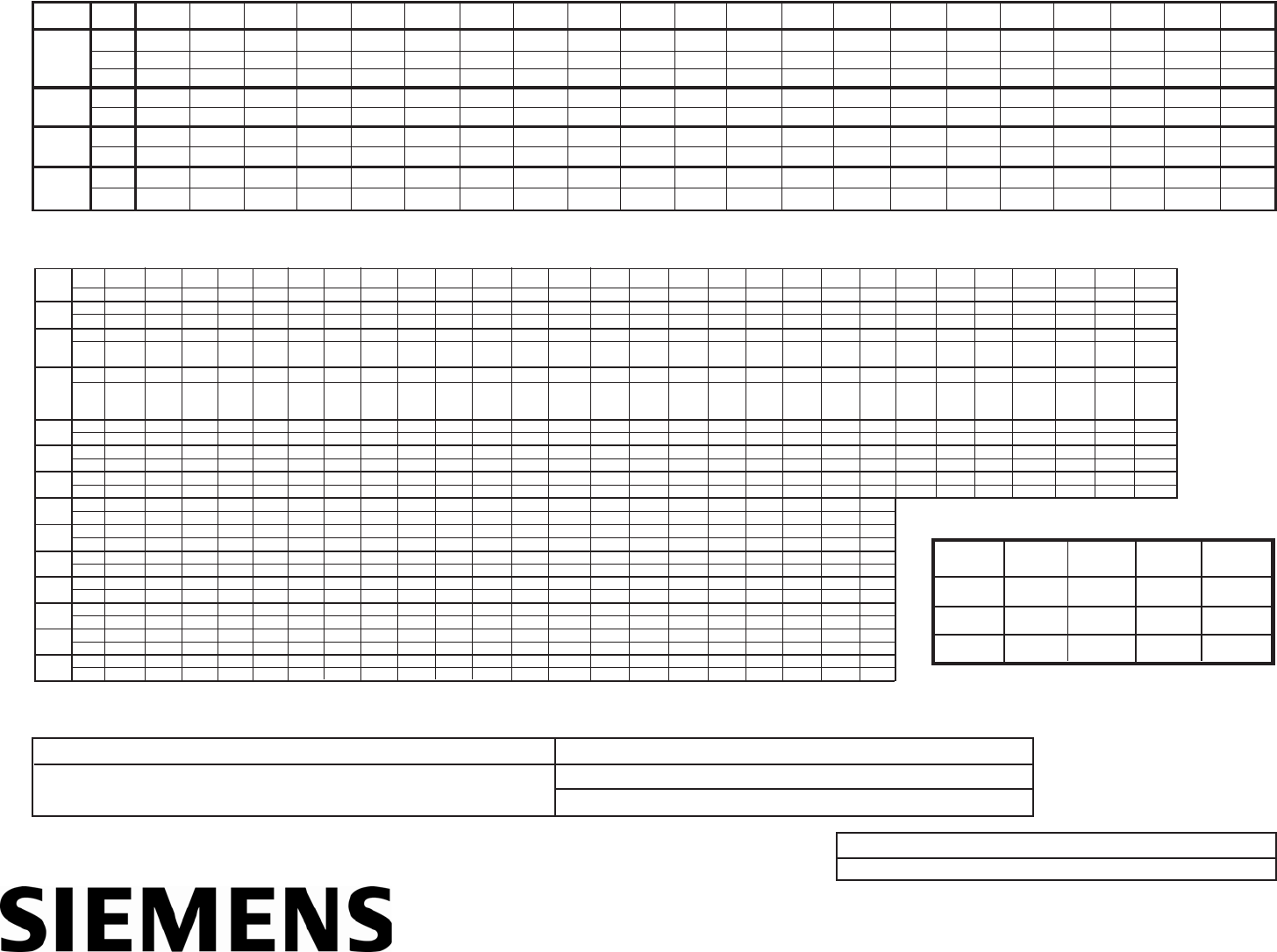
PIPE WEIGHT FORMULA FOR STEEL PIPE (lbs per foot)
10.68 (D-t) t, where D=Outside Diameter and t=Wall Thickness
UU
UU
U These materials are generally available in Schedules 40 and 80 only.
| Wall Thickness of Schedule 5S & 10S does not permit threading in
accordance with the American Standard for Pipe Threads (ASA No. B2.1)
99
99
9 Wall thickness identical with thickness of “Standard Weight” pipe.
^ Wall Thickness identical with thickness of “Extra-Heavy” pipe.
* These do not conform to American Standard B36. 10.
24.000
23.563
0.218
23.500
0.250
Sched.
0.840 1.050
0.710 0.920
0.065 0.065
0.674 0.884
0.083 0.083
0.622 0.824
0.10999
99
90.11399
99
9
0.546 0.742
^.147 ^.154
1/2 3/4
STAINLESS STEEL, HASTELLOY “C” & TITANIUMUU
UU
U PIPE
Size
O.D.
I.D.
Wall
I.D.
Wall
5S|
10S|
40S
80S
I.D.
Wall
I.D.
Wall
1.315 1.660
1.185 1.530
0.065 0.065
1.097 1.442
0.109 0.109
1.049 1.380
0.13399
99
90.14099
99
9
0.957 1.278
^.179 ^.191
1 1 1/4
1.900 2.375
1.770 2.245
0.065 0.065
1.682 2.157
0.109 0.109
1.610 2.067
0.14599
99
90.15499
99
9
1.500 1.939
^.200 ^.218
1 1/2 2
2.875 3.500
2.709 3.334
0.083 0.083
2.635 3.260
0.120 0.120
2.469 3.068
0.20399
99
90.21699
99
9
2.323 2.900
^.276 ^.300
2 1/2 3
4.000 4.500
3.834 4.334
0.083 0.083
3.760 4.260
0.120 0.120
3.548 4.026
0.22699
99
90.23799
99
9
3.364 3.826
^.318 ^.337
3 1/2 4
5.563 6.625
5.345 6.407
0.109 0.109
5.295 6.357
0.134 0.134
5.047 6.065
0.25899
99
90.28099
99
9
4.813 5.761
^.375 ^.432
56
8.625 10.750
8.407 10.482
0.109 0.134
8.329 10.420
0.148 0.165
7.981 10.020
0.32299
99
90.36599
99
9
7.625 9.750
^.500 ^.500
810
12.750 14.000
12.438 13.688
0.156 0.156
12.390 13.624
0.180 0.188
12.000
* .375
11.750
* .500
12 14
16.000 18.000
15.670 17.670
0.165 0.165
15.624 17.624
0.188 0.188
16 18
20.000 22.000
19.634 21.624
0.188 0.188
19.564 21.564
0.218 0.218
20 22 24
7.001 8.750 10.500 11.500 13.124 14.876 16.500 18.250 19.876
3.624 4.563 5.501 7.189 9.064 10.750 11.814 13.564 15.250 17.000 18.750 20.376
7.439 9.314 11.064 12.126 13.938 15.688 17.438 19.250 20.938
7.813 9.750 11.626 12.814 14.688 16.500 18.376 20.250 22.064
O.D.
I.D.
Wall
Pipe 1/2
CARBON STEEL and PVCUU
UU
U PIPE
Size
I.D
I.D.
Wall
11 1/2 2 1/2 4 6
Stand-
ard
I.D.
Extra
Strong
(XS)
^.147 ^.154 ^.179 ^.191 ^.200 ^.218 ^.276 ^.300 ^.318 ^.337 ^.375 ^.432 ^.500 0.593 0.687 0.750 0.843 0.937 1.031 1.125 1.218
Double
Extra
Strong
(XXS)
Sched.
10
Wall
Wall
I.D.
Wall
Sched.
20
I.D.
Wall
Sched.
30
I.D.
Wall
Sched.
40
I.D.
Wall
Sched.
60
I.D.
Wall
Sched.
80 I.D.
Wall
Sched.
100
I.D.
Wall
Sched.
120
I.D.
Wall
Sched.
140 I.D.
Wall
Sched.
160
3/4
0.840 1.050 1.315 1.660 1.900 2.375 2.875 3.500 4.000 4.500 5.563 6.625 8.625 10.750 12.750 14.000 16.000 18.000 20.000 22.000 24.000 26.000 28.000 30.000 32.000 34.000 36.000 42.000
0.10999
99
90.11399
99
90.13399
99
90.14099
99
90.14599
99
90.15499
99
90.20399
99
90.21699
99
90.22699
99
90.23799
99
90.25899
99
90.28099
99
90.32299
99
90.36599
99
90.406 0.438 ^.500 0.562 0.593 0.687
0.250 0.250 0.250 0.312 0.312 0.312 0.37599
99
90.37599
99
90.37599
99
9^.500 ^.500 ^.500 ^.500 ^.500 ^.500 ^.500
1 1/4 2 3 3 1/2 5 8 10 12 14 16 18 24 2826 30 32 34 36 4220 22
0.622 0.824 1.049 1.380 1.610 2.067 2.469 3.068 3.548 4.026 5.047 6.065 7.981 10.020 12.000 13.250 15.250 17.250 19.250 21.250 23.250 25.250 27.250 29.250 31.250 33.250 35.250 41.250
0.109 0.113 0.133 0.140 0.145 0.154 0.203 0.216 0.226 0.237 0.258 0.280 0.322 0.365 0.375 0.375 0.375 0.375 0.375 0.375 0.375 0.375 0.375 0.375 0.375 0.375 0.375 * .375
0.546 0.742 0.957 1.278 1.500 1.939 2.323 2.900 3.364 3.826 4.813 5.761 7.625 9.750 11.750 13.000 15.000 17.000 19.000 21.000 23.000 25.000 27.000 29.000 31.000 33.000 35.000 41.000
0.147 0.154 0.179 0.191 0.200 0.218 0.276 0.300 0.318 0.337 0.375 0.432 0.500 0.500 0.500 0.500 0.500 0.500 0.500 0.500 0.500 0.500 0.500 0.500 0.500 0.500 0.500 * .500
0.252 0.434 0.599 0.896 1.100 1.503 1.771 2.300 2.728 3.152 4.063 4.897 6.875 8.750 10.750
0.294 0.308 0.358 0.382 0.400 0.436 0.552 0.600 0.636 0.674 0.750 0.864 0.875 1.000 1.000
13.500 15.500 17.500 19.500 21.500 23.500 25.376 27.376 29.376 31.376 33.376 35.376
0.250 0.250 0.250 0.250 0.250 0.250 0.312 0.312 0.312 0.312 0.312 0.312
8.125 10.250 12.250 13.376 15.376 17.376 19.250 21.250 23.250 25.000 27.000 29.000 31.000 33.000 35.000 41.000
8.071 10.136 12.090 13.250 15.250 17.124 19.000 21.000 22.876 26.750 28.750 30.750 32.750 34.750 40.750
0.277 0.307 0.330 0.37599
99
90.37599
99
90.438 ^.500 ^.500 0.562 0.625 0.625 0.625 0.625 0.625 * .625
0.622 0.824 1.049 1.380 1.610 2.067 2.469 3.068 3.548 4.026 5.047 6.065 7.981 10.020 11.938 13.124 15.000 16.876 18.184 22.626
0.406 ^.500 0.562 0.593 0.656 0.750 0.812 0.875 0.968
0.546 0.742 0.957 1.278 1.500 1.939 2.323 2.900 3.364 3.826 4.813 5.761 7.625 9.564 11.376 12.500 14.314 16.126 17.938 19.750 21.564
0.593 0.718 0.843 0.937 1.031 1.156 1.281 1.375 1.531
0.438 0.500 0.562 0.718 0.843 1.000 1.093 1.218 1.375 1.500 1.625 1.812
0.812 1.000 1.125 1.250 1.438 1.562 1.750 1.875 2.062
0.466 0.614 0.815 1.160 1.338 1.689 2.125 2.624 3.438 4.313 5.189 6.813 8.500 10.126 11.188 12.814 14.438 16.064 17.750 19.314
0.187 0.218 0.250 0.250 0.281 0.343 0.375 0.438 0.531 0.625 0.718 0.906 1.125 1.312 1.406 1.593 1.781 1.968 2.125 2.343
Size 10 20 24 24
O.D. 10.750 20.000 24.000 24.000
I.D. 10.192 19.375 23.375 22.126
Wall 0.279 0.312 0.312 0.937
The above sizes are produced by pipe mills but
dimensions do not conform to any regular stan-
dard or schedule.
NON-STANDARD CARBON
Siemens Energy & Automation, Inc.
155 Plant Avenue, Hauppauge, New York 11788-3801
Tel. +1 (631) 231-3600 Toll Free. + 1 (800) 275-8479 Fax. +1 (631) 231-3334
Web: www.controlotron.com E-mail: info.ultrasonicflow@siemens.com

Siemens Energy & Automation, Inc.
Process Instrumentation Business Unit
CoC Ultrasonic Flow
155 Plant Avenue
Hauppauge, NY 11788
www.siemens.com/automation
