Siemens Syngo Ct Operator Manual Software Version 2005C Users C2 025.630.01.01.02_APPLICATIONGUIDE_SPIRIT
Software version syngo CT 2005C to the manual 9fe56ba5-2988-431d-8ea5-4581d0769415
2015-02-05
: Siemens Siemens-Syngo-Ct-Operator-Manual-Software-Version-Syngo-Ct-2005C-Users-Manual-410493 siemens-syngo-ct-operator-manual-software-version-syngo-ct-2005c-users-manual-410493 siemens pdf
Open the PDF directly: View PDF ![]() .
.
Page Count: 321 [warning: Documents this large are best viewed by clicking the View PDF Link!]
- User Documentation
- Scan and Reconstruction
- Dose Information
- Workflow Information
- Application Information
- Head
- Neck
- Shoulder
- Thorax
- Abdomen
- Pelvis
- Spine
- Upper Extremities
- Lower Extremities
- Vascular
- Specials
- Children
- Overview
- Hints in General
- HeadRoutine_Baby
- HeadRoutine_Child
- HeadSeq_Baby
- HeadSeq_Child
- InnerEar
- SinusOrbi
- Neck
- ThoraxRoutine_Baby
- ThoraxRoutine_Child
- ThoraxHRSeq_Baby
- ThoraxHRSeq_Child
- Abdomen_Baby
- Abdomen_Child
- Spine_Baby
- Spine_Child
- ExtrHR_Baby
- ExtrHR_Child
- HeadAngio
- HeadAngio08s
- CarotidAngio
- CarotidAngio08s
- BodyAngio
- BodyAngio08s
- NeonateBody
- syngo 3D
- syngo Fly Through
- syngo Dental CT
- syngo Osteo CT
- syngo Volume Evaluation
- syngo Dynamic Evaluation

SOMATOM
Spirit
Application Guide
Protocols
Principles
Helpful Hints
syngo 3D
syngo Fly Through
syngo Dental CT
syngo Osteo CT
syngo Volume Evaluation
syngo Dynamic Evaluation
Software Version syngo CT 2005C
C2-025.630.01.01.02_APPLICATIONGUIDE_SPIRIT.book Page 1 Friday, April 8, 2005 9:55 AM
2
The information presented in this Application Guide is
for illustration only and is not intended to be relied
upon by the reader for instruction as to the practice of
medicine. Any health care practitioner reading this
information is reminded that they must use their own
learning, training and expertise in dealing with their
individual patients.
This material does not substitute for that duty and is
not intended by Siemens Medical Solutions Inc., to be
used for any purpose in that regard. The drugs and
doses mentioned are consistent with the approval
labeling for uses and/or indications of the drug. The
treating physician bears the sole responsibility for the
diagnosis and treatment of patients, including drugs
and doses prescribed in connection with such use.
The Operating Instructions must always be strictly
followed when operating the CT System. The source
for the technical data is the corresponding data sheets.
The pertaining operating instructions must always be
strictly followed when operating the SOMATOM Spirit.
The statutory source for the technical data are the
corresponding data sheets.
We express our sincere gratitude to the many
customers who contributed valuable input.
Special thanks to Heike Theessen, Christiane
Bredenhöller, Kristin Pacheco, Karin Ladenburger, and
Chen Mahao for their valuable assistance.
To improve future versions of this Application Guide,
we would greatly appreciate your questions,
suggestions and comments.
Please contact us:
USC-Hotline:
Tel. no.+49-1803-112244
email ct-application.hotline@med.siemens.de
Editor: Ute Feuerlein
C2-025.630.01.01.02_APPLICATIONGUIDE_SPIRIT.book Page 2 Friday, April 8, 2005 9:55 AM

Overview
3
User Documentation 14
Scan and Reconstruction 16
Dose Information 28
Workflow Information 36
Application Information 54
Head 70
Neck 88
Shoulder 94
Thorax 98
Abdomen 110
Pelvis 124
Spine 132
Upper Extremities 146
C2-025.630.01.01.02_APPLICATIONGUIDE_SPIRIT.book Page 3 Friday, April 8, 2005 9:55 AM


5
C2-025.630.01.01.02_APPLICATIONGUIDE_SPIRIT.book Page 5 Friday, April 8, 2005 9:55 AM

6
Contents
User Documentation 14
Scan and Reconstruction 16
•Concept of Scan Protocols 16
•Scan Set Up 17
•Scan Modes 18
- Sequential Scanning 18
- Spiral Scanning 18
- Dynamic Serioscan 18
•Slice Collimation and Slice Width 19
- Slice Collimation and Slice Width for
Spiral Mode and HR Spiral Mode 20
- Slice Collimation and Slice Width for
Sequence Mode and HR Sequence Mode 20
•Increment 21
•Pitch 22
•Window values 23
•Kernels 24
•Image Filters 25
•Improved Head Imaging 27
Dose Information 28
•CTDIW and CTDIVol 28
•Effective mAs 30
•CARE Dose 32
- How does CARE Dose work? 32
Workflow Information 36
•Recon Jobs 36
•Examination Job Status 37
•Auto Load in 3D and Post-processing
Presets 38
•How to Create your own
Scan Protocols 39
- Edit/Save Scan Protocol 39
- Scan Protocol Manager 40
C2-025.630.01.01.02_APPLICATIONGUIDE_SPIRIT.book Page 6 Friday, April 8, 2005 9:55 AM

Contents
7
•Contrast Medium 45
- The Basics 45
-IV Injection 47
-Bolus Tracking 48
- Test Bolus using CARE Bolus 50
- Test Bolus 51
Application Information 54
•SOMATOM life 54
-General Information 54
-Key Features 55
- Description 56
- Access to Computer Based Training or
Manuals on CD ROM 57
- SRS Based Services 58
- Download of Files 59
- Contact incl. DICOM Images 60
- Trial Order and Installation 62
•Image Converter 64
•File Browser 66
•Patient Protocol 68
Head 70
•Overview 70
•Hints in General 71
- Head Kernels 71
•HeadRoutine 72
•HeadSeq 74
•InnerEarHR 76
•InnerEarHRSeq 78
•Sinus 80
•SinusSeq 82
•Orbita 84
•Dental 86
C2-025.630.01.01.02_APPLICATIONGUIDE_SPIRIT.book Page 7 Friday, April 8, 2005 9:55 AM

8
Contents
Neck 88
•Overview 88
•Hints in General 89
-Body Kernels 90
•Neck 92
Shoulder 94
•Overview 94
•Hints in General 95
-Body Kernels 95
•Shoulder 96
Thorax 98
•Overview 98
•Hints in General 99
- Body Kernels 101
•ThoraxRoutine/ThoraxRoutine08s 102
•ThoraxFast 104
•ThoraxHRSeq 106
•LungLowDose 108
Abdomen 110
•Overview 110
•Hints in General 111
- Body Kernels 113
•AbdomenRoutine/AbdomenRoutine08s 114
•AbdomenFast 116
•AbdMultiPhase/AbdMultiPhase08s 118
•AbdomenSeq 122
C2-025.630.01.01.02_APPLICATIONGUIDE_SPIRIT.book Page 8 Friday, April 8, 2005 9:55 AM

Contents
9
Pelvis 124
•Overview 124
•Hints in General 125
- Body Kernels 125
•Pelvis 126
•Hip 128
•SI_Joints 130
Spine 132
•Overview 132
•Hints in General 133
- Body Kernels 135
•C-Spine 136
•C-SpineSeq 138
•Spine 140
•SpineSeq 142
•Osteo 144
Upper Extremities 146
•Overview 146
•Hints in General 147
- Body Kernels 148
•WristHR 150
•ExtrRoutineHR 152
Lower Extremities 154
•Overview 154
•Hints in General 155
- Body Kernels 156
•KneeHR 158
•FootHR 160
•ExtrRoutineHR 161
C2-025.630.01.01.02_APPLICATIONGUIDE_SPIRIT.book Page 9 Friday, April 8, 2005 9:55 AM

10
Contents
Vascular 162
•Overview 162
•Hints in General 163
- Head Kernels 163
- Body Kernels 163
•HeadAngio/HeadAngio08s 164
•CarotidAngio/CarotidAngio08s 166
•ThorAngio/ThorAngio08s 168
•Embolism 170
•BodyAngioRoutine/BodyAngioRoutine08s 172
•BodyAngioFast 174
Specials 176
•Overview 176
- Trauma 176
- Interventional CT 176
- Test Bolus 176
•Trauma 177
- The Basics 177
•PolyTrauma 178
•HeadTrauma 180
•Interventional CT 181
•Biopsy 182
•TestBolus 183
Children 184
•Overview 184
•Hints in General 187
- Head Kernels 190
- Body Kernels 191
•HeadRoutine_Baby 192
•HeadRoutine_Child 194
•HeadSeq_Baby 196
•HeadSeq_Child 198
•InnerEar 200
•SinusOrbi 202
•Neck 204
C2-025.630.01.01.02_APPLICATIONGUIDE_SPIRIT.book Page 10 Friday, April 8, 2005 9:55 AM

Contents
11
•ThoraxRoutine_Baby 206
•ThoraxRoutine_Child 208
•ThoraxHRSeq_Baby 210
•ThoraxHRSeq_Child 212
•Abdomen_Baby 214
•Abdomen_Child 216
•Spine_Baby 218
•Spine_Child 220
•ExtrHR_Baby 222
•ExtrHR_Child 224
•HeadAngio 226
•HeadAngio08s 228
•CarotidAngio 230
•CarotidAngio08s 232
•BodyAngio 234
•BodyAngio08s 236
•NeonateBody 238
syngo 3D 240
- Multi Planar Reconstruction (MPR) 240
- Maximum Intensity Projection (MIP) 240
- Shaded Surface Display (SSD) 241
- Volume Rendering Technique (VRT) 241
- Prerequisites 242
•Workflow 242
- Loading the Images 242
- Creating Series 244
- Editing 246
- Documentation of Results 249
•Workflow for a CT Extremity Examination 250
- Using MPR/MPR Thick 250
- Using SSD 251
- Using VRT 251
•Workflow for a CT Angiography 252
- Using MIP/MIP Thin 252
- Using VRT/VRT Thin/Clip 253
•Hints in General 254
- Setting Views in the Volume Data Set 254
- Changing /Creating VRT Presets 255
C2-025.630.01.01.02_APPLICATIONGUIDE_SPIRIT.book Page 11 Friday, April 8, 2005 9:55 AM

12
Contents
- Auto Load in 3D and Post-processing
Presets 257
- Blow-up Mode 257
syngo Fly Through 258
•Key Features 258
•Prerequisites 259
•The Basics for CT Virtual Endoscopy 259
- SSD and VRT Presets for Endoscopic
Renderings 259
- Endoscopic Viewing Parameters/
Fly Cone Settings 260
- Patient Preparation 262
•Workflow 263
- Navigation of the Endoscopic Volume 265
- Fly Path Planning 266
syngo Dental CT 268
•The Basics 268
•Scan Protocols 269
•Additional Important Information 271
syngo Osteo CT 274
•The Basics 274
•Scanning Procedure 275
•Configuration 278
•Evaluation Workflow 282
•Additional Important Information 287
syngo Volume Evaluation 288
•Prerequisites 290
•Workflow 291
•General Hints 300
•Configuration 303
C2-025.630.01.01.02_APPLICATIONGUIDE_SPIRIT.book Page 12 Friday, April 8, 2005 9:55 AM

Contents
13
syngo Dynamic Evaluation 306
•Prerequisites 308
•Workflow 309
- 1. Loading the Images 309
- 2. Inspecting the Input Images 310
- 3. Generation of Parameter Images 310
- 4. Creating a Baseline Image 313
- 5. Evaluation of Region of Interests 314
- 6. Enhancement Curve 315
- 7. Documentation of Results 316
•General Hints 317
C2-025.630.01.01.02_APPLICATIONGUIDE_SPIRIT.book Page 13 Friday, April 8, 2005 9:55 AM

14
For further information about the basic operation,
please refer to the corresponding syngo CT Operator
Manual:
syngo CT Operator Manual
Volume 1:
Security Package
Basics
Preparations
Examination
CARE Bolus CT
syngo CT Operator Manual
Volume 2:
syngo Patient Browser
syngo Viewing
syngo Filming
syngo 3D
syngo CT Operator Manual
Volume 3:
syngo Data Set Conversion
syngo Dental CT
syngo Dynamic Evaluation
syngo Osteo CT
syngo Volume
User Documentation
C2-025.630.01.01.02_APPLICATIONGUIDE_SPIRIT.book Page 14 Friday, April 8, 2005 9:55 AM

User Documentation
15
C2-025.630.01.01.02_APPLICATIONGUIDE_SPIRIT.book Page 15 Friday, April 8, 2005 9:55 AM

16
Scan and Reconstruction
Concept of Scan Protocols
The scan protocols for adult and children are defined
according to body regions – Head, Neck, Shoulder,
Thorax, Abdomen, Pelvis, Spine, Upper Extremities,
Lower Extremities, Specials, and Vascular.
The general concept is as follows: All protocols without
suffix are standard spiral modes. E.g., “Shoulder”
means the spiral mode for the shoulder.
The suffixes of the protocol name are follows:
“Routine“: for routine studies
“Seq”: for sequence studies
“Fast“: use a higher pitch for fast acquisition
“HR“: use a thinner slice width (1.0 mm) for High Res-
olution studies and a thicker slice width for soft tissue
studies
The availability of scan protocols depends on the sys-
tem configuration.
C2-025.630.01.01.02_APPLICATIONGUIDE_SPIRIT.book Page 16 Friday, April 8, 2005 9:55 AM

Scan and Reconstruction
17
Scan Set Up
Scans can be simply set up by selecting a predefined
examination protocol. To repeat any mode, just click
the chronicle with the right mouse button for “repeat”.
To delete it, select “cut“. Each range name in the chron-
icle can be easily changed before “load“.
Multiple ranges can be run either automatically with
“auto range“, which is denoted by a bracket connecting
the two ranges, or separately with a “pause” in
between.
C2-025.630.01.01.02_APPLICATIONGUIDE_SPIRIT.book Page 17 Friday, April 8, 2005 9:55 AM

18
Scan and Reconstruction
Scan Modes
Sequential Scanning
This is an incremental, slice-by-slice imaging mode in
which there is no table movement during data acquisi-
tion. A minimum interscan delay in between each
acquisition is required to move the table to the next
slice position.
Spiral Scanning
Spiral scanning is a continuous volume imaging mode.
The data acquisition and table movements are per-
formed simultaneously for the entire scan duration.
There is no interscan delay and a typical range can be
acquired in a single breath hold.
Each acquisition provides a complete volume data set,
from which images with overlapping can be recon-
structed at any arbitrary slice position. Unlike the
sequence mode, spiral scanning does not require addi-
tional radiation to obtain overlapping slices.
Dynamic Serioscan
Dynamic serial scanning mode without table feed.
Dynamic serio can still be used for dynamic evaluation,
such as Test Bolus.
C2-025.630.01.01.02_APPLICATIONGUIDE_SPIRIT.book Page 18 Friday, April 8, 2005 9:55 AM

Scan and Reconstruction
19
Slice Collimation and
Slice Width
Slice collimation is the slice thickness resulting from
the effect of the tube-side collimator and the adaptive
detector array design. In Multislice CT, the Z-coverage
per rotation is given by the product of the number of
active detector slices and the collimation (e.g., 2 x
1.0 mm).
Slice width is the FWHM (full width at half maximum)
of the reconstructed image.
With the SOMATOM Spirit, you select the slice collima-
tion together with the slice width desired. The slice
width is independent of pitch, i.e. what you select is
always what you get. Actually, you do not need to be
concerned about the algorithm any more; the software
does it for you.
The Recon icon on the chronicle will be labeled with
“RT”. After the scan, the Real Time displayed image
series has to be reconstructed.
The following tables show the possibilities of image
reconstruction in spiral and sequential scanning.
C2-025.630.01.01.02_APPLICATIONGUIDE_SPIRIT.book Page 19 Friday, April 8, 2005 9:55 AM

20
Scan and Reconstruction
Slice Collimation and Slice Width for Spiral Mode
and HR Spiral Mode
Slice Collimation and Slice Width for Sequence
Mode and HR Sequence Mode
1 mm: 1, 1.25, 2, 3, 5 mm
1.5 mm: 2, 3, 5, 6 mm
2.5 mm: 3, 5, 6, 8, 10 mm
4 mm: 5, 6, 8, 10 mm
5 mm: 6, 8, 10 mm
1.0 mm: 1, 2 mm
1.5 mm: 1.5, 3 mm
2.5 mm: 2.5, 5 mm
4.0 mm: 4, 8 mm
5.0 mm 5, 10 mm
C2-025.630.01.01.02_APPLICATIONGUIDE_SPIRIT.book Page 20 Friday, April 8, 2005 9:55 AM

Scan and Reconstruction
21
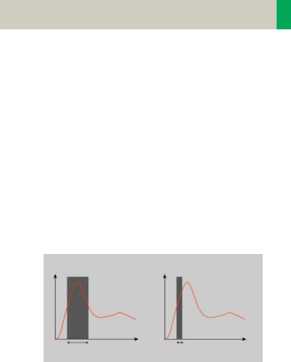
Increment
The increment is the distance between the recon-
structed images in the Z direction. When the increment
chosen is smaller than the slice thickness, the images
are created with an overlap. This technique is useful to
reduce partial volume effect, giving you better detail of
the anatomy and high quality 2D and 3D post-process-
ing.
Reconstruction Increment
Slice Thickness = 10 mm
Increment = 10 mm Increment = 5 mm
Increment = 3 mm
C2-025.630.01.01.02_APPLICATIONGUIDE_SPIRIT.book Page 21 Friday, April 8, 2005 9:55 AM

22
Scan and Reconstruction
Pitch
In single slice CT:
Pitch = table movement per rotation/slice collimation
E.g.,: slice collimation = 5 mm,
table moves 5 mm per rotation, then pitch = 1.
With the Siemens Multislice CT, we differentiate
between:
Feed/Rotation, the table movement per rotation
Volume Pitch, table movement per rotation/single
slice collimation.
Pitch Factor, table movement per rotation/complete
slice collimation.
E.g., slice collimation = 2 x 5 mm,
table moves 10 mm per rotation,
then Volume Pitch = 2, Pitch Factor = 1.
With the SOMATOM Spirit, the pitch, slice, collimation,
rotation time, and scan range can be adjusted. The
pitch factor can be selected from 0.5-2.
Pitch Models
Pitch 1 Pitch 1.5 Pitch 2
C2-025.630.01.01.02_APPLICATIONGUIDE_SPIRIT.book Page 22 Friday, April 8, 2005 9:55 AM
Scan and Reconstruction
23
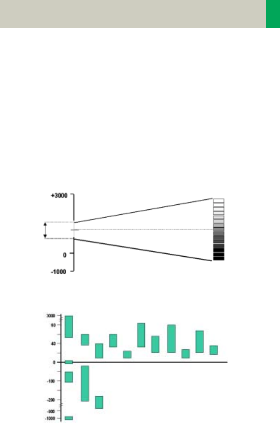
Window values
The Scale of the CT Hounsfield Units is from -1024 to
+3071.
The displayed window values have to correspond to
the anatomical structure.
Windowing is used to optimize contrast and brightness
of images.
Organ specific window values
Gray scale
white
black
CT-window values
Window
center C
Window
width W
Hounsfield Units
Spleen Kidneys
Blood
Heart
Liver
Tumor
Bladder
Colon
Pancreas Adrenal
Glands
Bones
Water
Breast
Fat
Lung
Air
C2-025.630.01.01.02_APPLICATIONGUIDE_SPIRIT.book Page 23 Friday, April 8, 2005 9:55 AM

24
Scan and Reconstruction
Kernels
There are 3 different types of kernels: “H“ stands for
Head, “B“ stands for Body, “C“ stands for ChildHead.
The image sharpness is defined by the numbers – the
higher the number, the sharper the image; the lower
the number, the smoother the image.
A set of 18 kernels is supplied, consisting of:
• 6 body kernels: smooth (B20s), medium smooth
(B31s), medium (B41s), medium sharp (B50s), sharp
(B60s), high res (B70s)
• 7 head kernels: smooth (H21s), medium smooth
(H31s), medium (H41s), medium sharp (H50s),
sharp (H60s), high res (H70s), ultra high res (H80s)
• 3 child head kernels: smooth (C20s), medium
(C30s), sharp (C60s)
• 2 special kernels: S80s, U90s
Note: Do not use different kernels for body parts other
than what they are designed for.
For further information regarding the kernels, please
refer to the “Hints in General” of the corresponding
body region.
C2-025.630.01.01.02_APPLICATIONGUIDE_SPIRIT.book Page 24 Friday, April 8, 2005 9:55 AM
Scan and Reconstruction
25
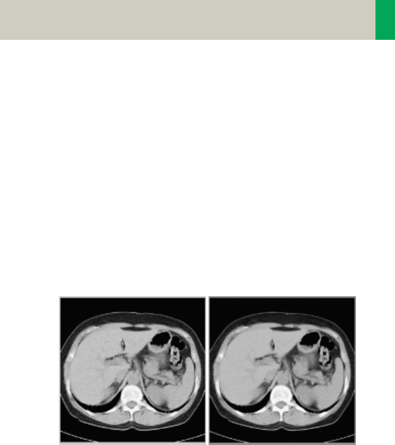
Image Filters
There are 3 different filters available:
LCE: The Low-contrast enhancement (LCE) filter
enhances low-contrast detectability. It reduces the
image noise.
• Similar to reconstruction with a smoother kernel
• Reduces noise
• Enhances low-contrast detectability
• Adjustable in four steps
• Automatic post-processing
C2-025.630.01.01.02_APPLICATIONGUIDE_SPIRIT.book Page 25 Friday, April 8, 2005 9:55 AM
26
Scan and Reconstruction
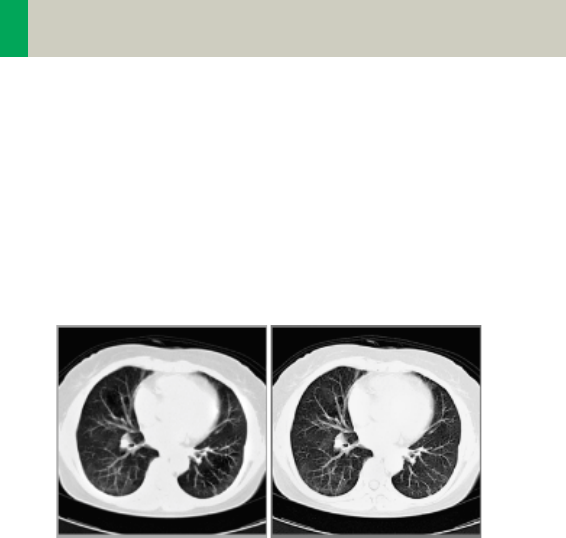
HCE: The High-contrast enhancement (HCE) filter
enhances high-contrast detectability. It increases the
image sharpness, similar to reconstruction with a
sharper kernel.
• Increases sharpness
• Faster than raw-data reconstruction
• Enhances high-contrast detectability
• Automatic post-processing
ASA: The Advanced Smoothing Algorithm (ASA) fil-
ter reduces noise in soft tissue, while edges with high
contrast are preserved.
• Reduces noise without blurring of edges
• Enhances low-contrast detectability
• Individually adaptable
• Automatic post-processing
C2-025.630.01.01.02_APPLICATIONGUIDE_SPIRIT.book Page 26 Friday, April 8, 2005 9:55 AM

Scan and Reconstruction
27
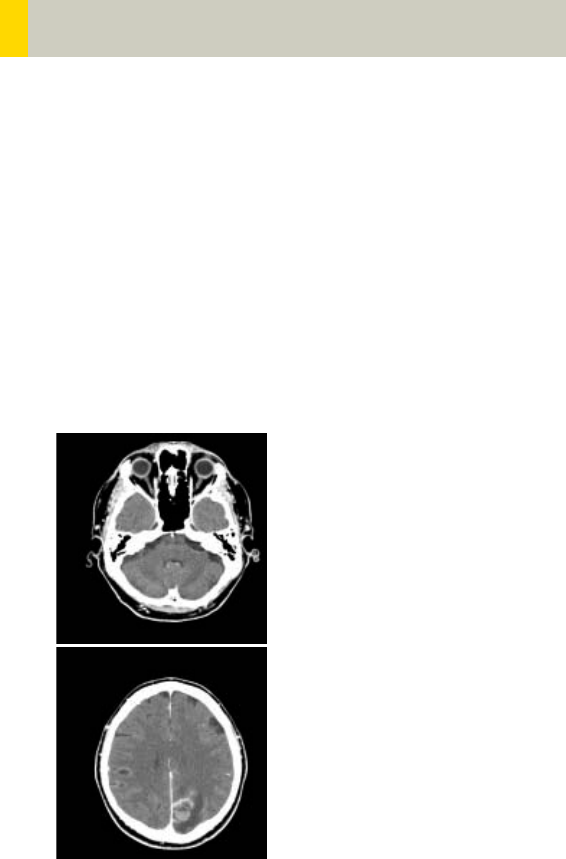
Improved Head Imaging
An automatic bone correction algorithm has been
included in the standard image reconstruction. Using a
new iterative technique, typical artifacts arising from
the beam-hardening effect, e.g., Hounsfield bar, are
minimized without any additional post-processing.
This advanced algorithm allows for excellent images of
the posterior fossa, but also improves head image
quality in general. Bone correction is activated auto-
matically for body region “Head”.
In order to optimize image quality versus radiation
dose, scans in the body region “Head” are provided
within a maximum scan field of 300 mm with respect
to the iso-center. No recon job with a field of view
exceeding those limits will be possible. Therefore,
patient positioning has to be performed accurately to
ensure a centered location of the skull.
Head image without
correction.
Head image with cor-
rections.
C2-025.630.01.01.02_APPLICATIONGUIDE_SPIRIT.book Page 27 Friday, April 8, 2005 9:55 AM

28
Dose Information
CTDIW and CTDIVol
The average dose in the scan plane is best described by
the CTDIW for the selected scan parameters. The CTDIW
is measured in the dedicated plastic phantoms – 16 cm
diameter for head and 32 cm diameter for body (as
defined in IEC 60601 –2 – 44). This dose number gives
a good estimate for the average dose applied in the
scanned volume as long as the patient size is similar to
the size of the respective dose phantoms.
Since the body size can be smaller or larger than
32 cm, the CTDIW value displayed can deviate from the
dose in the scanned volume.
The CTDIW definition and measurement is based on sin-
gle axial scan modes. For clinical scanning, i.e. scan-
ning of entire volumes in patients, the average dose
will also depend on the table feed in between axial
scans or the feed per rotation in spiral scanning. The
dose, expressed as the CTDIW, must therefore be cor-
rected by the Pitch Factor of the spiral scan or an axial
scan series to describe the average dose in the scanned
volume.
For this purpose the IEC defined the term “CTDIVol“ in
September 2002:
This dose number is displayed on the user interface for
the selected scan parameters.
CTDIVol = CTDIW/Pitch Factor
C2-025.630.01.01.02_APPLICATIONGUIDE_SPIRIT.book Page 28 Friday, April 8, 2005 9:55 AM

Dose Information
29
The CTDIvol value does not provide the entire informa-
tion of the radiation risk associated with CT examina-
tion. For the purpose, the concept of the “Effective
Dose“ was introduced by ICRP (International Commis-
sion on Radiation Protection). The effective dose is
expressed as a weighted sum of the dose applied not
only to the organs in the scanned range, but also to the
rest of the body. It could be measured in whole body
phantoms (Alderson phantom) or simulated with
Monte Carlo techniques.
The calculation of the effective dose is rather compli-
cated and has to be done by sophisticated programs.
These have to take into account the scan parameters,
the system design of individual scanner, such as x-ray
filtration and gantry geometry, the scan range, the
organs involved in the scanned range and the organs
affected by scattered radiation. For each organ, the
respective dose delivered during the CT scanning has
to be calculated and then multiplied by its radiation
risk factor. Finally, the weighted organ dose numbers
are added up to get the effective dose.
The concept of effective dose allows the comparison of
radiation risk associated with different CT or x-ray
exams, i.e. different exams associated with the same
effective dose would have the same radiation risk for
the patient. It also allows comparing the applied x-ray
exposure to the natural background radiation,
e.g., 2 – 3 mSv per year in Germany.
C2-025.630.01.01.02_APPLICATIONGUIDE_SPIRIT.book Page 29 Friday, April 8, 2005 9:55 AM

30
Dose Information
Effective mAs
In sequential scanning, the dose (Dseq) applied to the
patient is the product of the tube current-time (mAs)
and the CTDIw per mAs:
In spiral scanning, however, the applied dose (Dspiral)
is influenced by the “classical“ mAs (mA x Rot Time)
and in addition by the Pitch Factor. For example, if a
Multislice CT scanner is used, the actual dose applied
to the patient in spiral scanning will be decreased
when the Pitch Factor is larger than 1, and increased
when the Pitch Factor is smaller than 1. Therefore, the
dose in spiral scanning has to be corrected by the Pitch
Factor:
To make it easier for the users, the concept of the
“effective“ mAs was introduced with the SOMATOM
Multislice scanners.
The effective mAs takes into account the influence of
pitch on both the image quality and dose:
To calculate the dose you simply have to multiply the
CTDIw per mAs with the effective mAs of the scan:
Dseq = DCTDIw x mAs
Dspiral = (DCTDIw x mA x Rot Time)/Pitch Factor
Effective mAs = mAs/Pitch Factor
Dspiral = DCTDIw x effective mAs
C2-025.630.01.01.02_APPLICATIONGUIDE_SPIRIT.book Page 30 Friday, April 8, 2005 9:55 AM

Dose Information
31
For spiral scan protocols, the indicated mAs is the
effective mAs per image. The correlation between tube
current mA and effective mAs of spiral scans on a Mul-
tislice CT scanner is given by the following formula:
where Slice collimation refers to the collimation of one
detector row, and nrow is the number of used detector
rows.
Pitch Factor =Feed/Rot
nrow x Slice collimation
mA = effective mAs x Pitch Factor
R o t T i m e
Effective mAs = mA x RotTime/Pitch Factor
C2-025.630.01.01.02_APPLICATIONGUIDE_SPIRIT.book Page 31 Friday, April 8, 2005 9:55 AM

32
Dose Information
CARE Dose
CARE Dose is a clinical application package that pro-
vides real-time tube current modulation for Spiral and
Sequential Scanning.
CARE Dose reduces patient dose significantly, espe-
cially in the regions of shoulder and pelvis. It decreases
tube load, which extends the capacity for volume scan-
ning with thinner slices, larger volumes or Multi-phase
studies.
It can also improve image quality by increasing mA,
thus reducing image noise on the lateral views.
How does CARE Dose work?
It reduces the mA for low attenuation views up to 90%
and keeps the nominal higher mA for high attenuation
views, e. g. in the lateral projection. This is done “on-
the-fly”, i.e. the scanner adapts the mA in real-time,
according to the patient’s attenuation profile.
C2-025.630.01.01.02_APPLICATIONGUIDE_SPIRIT.book Page 32 Friday, April 8, 2005 9:55 AM
Dose Information
33
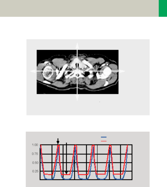
Example of scanning the shoulder region.
Principle of CARE Dose tube current adaption.
• CARE Dose is pre-selected by default for most stan-
dard protocols. It can be switched on/off in the Scan
subtask card.
High
attenuation
,
high mA
Low attenuation,
low mA
Object attenuation
Modulated tube current
lateral
TOP
time
rel. units
C2-025.630.01.01.02_APPLICATIONGUIDE_SPIRIT.book Page 33 Friday, April 8, 2005 9:55 AM

34
Dose Information
• For the average patients examination, CARE Dose
does not require any manual changes to the scan
protocol. However, the mAs must be adapted manu-
ally for obese and pediatric patients.
• The mean value of the mAs applied will be lower
than what you have selected. Although the average
mA for the entire scan will be lower than selected,
we allow the scanner to apply increased mA levels
for the high attenuation views. This may cause dif-
ferent results of the tube load controller when
switching on and off CARE Dose.
• The mean value of the effective mAs applied is
shown in the image text.
C2-025.630.01.01.02_APPLICATIONGUIDE_SPIRIT.book Page 34 Friday, April 8, 2005 9:55 AM

Dose Information
35
C2-025.630.01.01.02_APPLICATIONGUIDE_SPIRIT.book Page 35 Friday, April 8, 2005 9:55 AM

36
Workflow Information
Recon Jobs
In the Recon card, you can define up to 3 reconstruc-
tion jobs for each range with different parameters,
either before or after you acquire the data. When you
deselect all chronicle entries, all open recon jobs will
be automatically reconstructed after you click on
“Recon“. In case you want to add more than 3 recon
jobs, simply click the icon on the chronicle with the
right mouse button and select “delete recon job“ to
delete the one which has been completed, and then
one more recon job will be available in the Recon card.
Note: What you delete is just the job from the display,
not the images that have been reconstructed. Once
reconstructed, these completed recon jobs stay in the
browser, until deleted from the hard drive.
C2-025.630.01.01.02_APPLICATIONGUIDE_SPIRIT.book Page 36 Friday, April 8, 2005 9:55 AM

Workflow Information
37
Examination Job Status
You can get an overview of all recon jobs by clicking on
the recon task symbol in the status bar or selecting
Transfer – Examination Job Status in the main menu of
the Patient Browser.
The Examination Job Status dialog will appear where
all recon jobs (completed, queued and in work) are
listed. You can stop, restart and delete each job by
clicking the according button. To give a selected job a
higher priority click “urgent”.
The column “Type“ shows you which kind of recon-
struction is queued.
Two types are displayed:
–Recon
all recon jobs from the Recon card
–Auto 3D
all 3D reconstructions which you have sent via “Auto
post-processing” automatically into the 3D card.
These jobs will be deleted from the job list as soon as
the patient is closed in the 3D card.
C2-025.630.01.01.02_APPLICATIONGUIDE_SPIRIT.book Page 37 Friday, April 8, 2005 9:55 AM

38
Workflow Information
Auto Load in 3D and Post-
processing Presets
You can activate the Auto load in 3D function on the
Examination card/Auto Tasking and link it to a recon
job. For example, the 2nd recon job with thinner slice
width in some of the examination protocols.
On the 3D card you have the ability to create Range
Parallel and Radial protocols for Multi-Planar-Recon-
struction (MPR) and Thin Maximum-Intensity-Projec-
tion (MIP Thin) which can be linked to a special series.
For example, if you always do sagittal MPRs for a Spine
examination, once you load a Spine examination into
the 3D card, select the image type (MPR, MIP Thin),
select the orientation and open the Range Parallel
function. Adapt the range settings (Image thickness,
Distance between the images etc.) and hit the link but-
ton. From that point on, you have a predefined post-
processing protocol, linked to the series description of
a Spine examination.
The same can be done for VRT presets. In the main
menu, under Type/VRT Definition, you can link VRT pre-
sets with a series description.
C2-025.630.01.01.02_APPLICATIONGUIDE_SPIRIT.book Page 38 Friday, April 8, 2005 9:55 AM

Workflow Information
39
How to Create your own
Scan Protocols
There are two different ways to modify and create your
scan protocols:
Edit/Save Scan Protocol
If you want to modify an existing protocol or create a
new one, e.g., you want to have two “AbdomenRou-
tine-Protocols” with different slice width, we recom-
mend to do this directly on the Examination card.
User-specific scan protocols can be saved with the fol-
lowing basic procedure:
• Register a patient, you can choose any patient posi-
tion in the “Patient Model Dialog“.
• Select an existing scan protocol in the “Patient Model
Dialog”.
• Modify the scan protocol, change parameters, add
new ranges etc., so that the new protocols fit your
needs.
• Scan your patient as usual.
• Check if all parameters are as you desire.
•Select Edit/Save Scan Protocol in the main menu.
• Select the folder where you want the new protocol to
appear and the scan protocol name in the pop-up
dialog.
• You can either use the same name to overwrite the
existing scan protocol, or enter a new name, which
will create a new protocol name and will not alter
any of the existing protocols already stored.
C2-025.630.01.01.02_APPLICATIONGUIDE_SPIRIT.book Page 39 Friday, April 8, 2005 9:55 AM

40
Workflow Information
Hints
• You can save your scan protocol at any time of the
examination.
• It is recommended that you save your own scan pro-
tocol with a new name in order to avoid overwriting
the default scan protocol.
• Do not use special characters. In addition, do not
even use any blank spaces. Allowed are all numbers
from 0 to 9, all characters from A to Z and a to z and
explicitly the _ (underscore).
• Do not rename scan protocol files on Windows level.
This will lead to inconsistencies.
• You can now save your own scan protocols in any
predefined folder. The organ characteristics will
belong to the scan protocol not to the region.
• In the Patient Model Dialog, the modified scan proto-
cols are marked with a dot in front of the protocol.
Scan Protocol Manager
If you want to modify special parameters for all exist-
ing scan protocols or you want to modify the folder
structure, we recommend doing this in the “Scan Pro-
tocol Manager”. The “Scan Protocol Manager” is
opened and all protocols are loaded.
User-specific scan protocols can be saved with the fol-
lowing basic procedure:
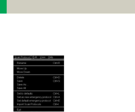
Open “Options, on the “Scan Protocol Manager” icon.
• Rename a protocol:
Select a scan protocol with the right mouse button.
Select “Rename” and enter a new name for the pro-
tocol.
C2-025.630.01.01.02_APPLICATIONGUIDE_SPIRIT.book Page 40 Friday, April 8, 2005 9:55 AM
Workflow Information
41
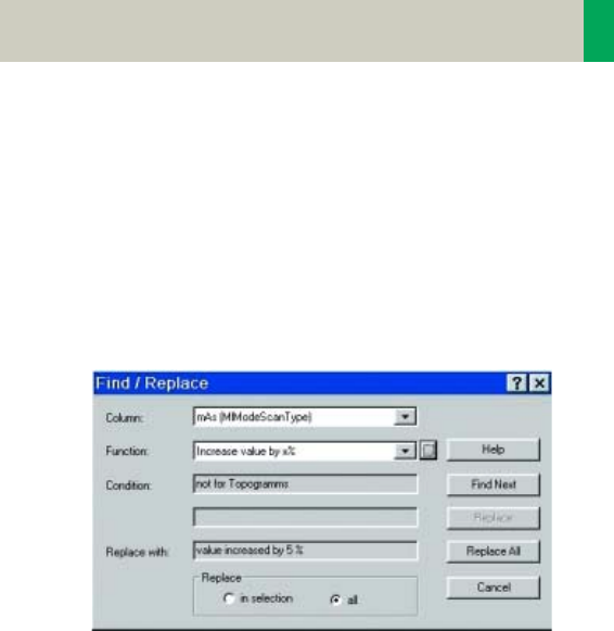
• Change one (or more) parameters for all Customer
protocols:
Select “Edit – Find/Replace”. Open the “Column“ list
box and choose the desired parameter. Select a new
function of this parameter in the “Function“ list box.
Under the button next to the Function entry you can
choose special selections, e.g., you can in-/decrease
all mAs values by a certain percentage, e.g., 5%.
Select “Replace All”.
C2-025.630.01.01.02_APPLICATIONGUIDE_SPIRIT.book Page 41 Friday, April 8, 2005 9:55 AM
42
Workflow Information
• Define a protocol as Emergency protocol.
Select the desired scan protocol with the right
mouse button. Select entry “Set as new emergency
protocol”. The selected protocol is marked with a red
cross.
• Change the structure of the protocol tree. You can
sort all Customers protocols as needed. Select the
desired protocols, press right mouse button.
You will find the entries:
– Cut/copy
– Paste
to change the sorting of your protocol tree. You can
also do this easily by dragging and dropping the pro-
tocols under the desired position.
C2-025.630.01.01.02_APPLICATIONGUIDE_SPIRIT.book Page 42 Friday, April 8, 2005 9:55 AM

Workflow Information
43
Hints
• With the Find/Replace function you can easily insert
an API command for all protocols as needed.
• Also all Auto Tasking actions, e.g., the transfer to
configured network nodes can be set within one
action. Within the “Function” button you can set your
transfer actions depending on the slice width.
• By sorting the scan protocols, all organ characteris-
tics will belong to the protocol, so it does not matter
which folder you choose.
• The entry “Set to defaults” in the main menu/ context
sensitive menu will reset all your changes to the Sie-
mens default values.
• Display of actions:
– Invalid protocols or parameters are marked in yel-
low.
– Changed, but not yet saved protocols and/or
parameters are marked in green.
• With the entries Save/Save as/Save all, you can save
your changes.
• For security purposes it is not possible to do any
changes in the Siemens protocols, although you can
copy or drag&drop these protocols into a Customer
folder.
• Scan protocols can be deleted if they belong to the
USER category. Only complete scan protocols can be
deleted. It isn’t possible to delete scan protocol
entries or scan protocol recon jobs.
• If there are unsaved scan protocols when closing the
Scan Protocol Manager you will be informed by a
message.
• You can configure the displayed columns and their
position with “View configure columns”.
C2-025.630.01.01.02_APPLICATIONGUIDE_SPIRIT.book Page 43 Friday, April 8, 2005 9:55 AM

44
Workflow Information
Additional Information:
1.System/Run offers the tool “Restore Default Scan Pro-
tocols“ which allows you to remove user specific
scan protocols and to restore the Siemens default
settings.
2.The main menu entry “Edit” offers save/delete Scan
Protocols.
3.System/Run or the main menu entry “View” in the
Scan Protocol Manager offer the tool “List Scan Pro-
tocols” which generates an HTML table of all avail-
able scan protocols. This list can be printed or saved
on Floppy (Right-click in the table, click View Source/
File/Save As…).
C2-025.630.01.01.02_APPLICATIONGUIDE_SPIRIT.book Page 44 Friday, April 8, 2005 9:55 AM
Workflow Information
45
Contrast Medium
The Basics
The administration of intravenous (IV) contrast mate-
rial during spiral scanning improves the tissue charac-
terization and characterization of lesions, as well as the
opacity of vessels. The contrast scan will yield good
results only if the acquisition occurs during the optimal
phase of enhancement in the region of interest. There-
fore, it is essential to initiate the acquisition with the
correct start delay. Since multislice spiral CT can pro-
vide much faster speed and shorter acquisition time, it
is even more critical to get the right timing to achieve
optimal results.
The dynamics of the contrast enhancement is deter-
mined by:
• Patient cardiac output
•Injection rate
• Total volume of contrast medium injected
• Concentration of the contrast medium
• Type of injection – uni-phasic or bi-phasic
• Patient pathology
Longer scan time Shorter scan time
40 s scan 10 s scan
C2-025.630.01.01.02_APPLICATIONGUIDE_SPIRIT.book Page 45 Friday, April 8, 2005 9:55 AM
46
Workflow Information
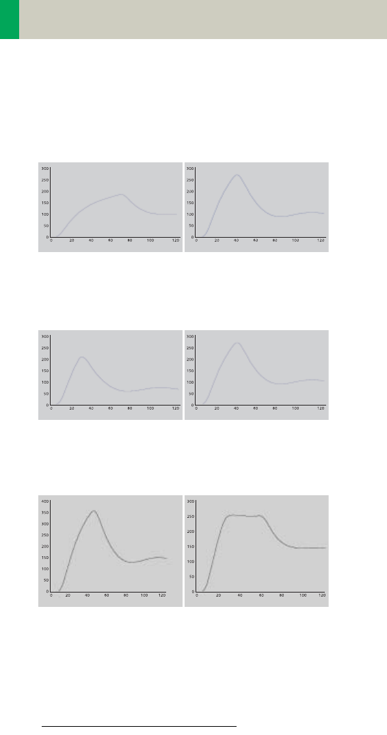
Aortic time-enhancement curves after i.v. contrast
injection (computer simulation*).
All curves are based on the same patient parameters
(male, 60-year-old, 75 kg).
*Radiology 1998; 207:647 – 655
2 ml/s, 120 ml, 300 mg I/ml 4 ml/s, 120 ml, 300 mg I/ml
80 ml, 4 ml/s, 300 mg I/ml 120 ml, 4 ml/s, 300 mg I/ml
Uni-phase 140 ml, 4 ml/s,
370 mg I/ml
Bi-phase 70 ml, 4 ml/s,
plus 70 ml,
2 ml/s, 370 mg I/ml
Time [s]
Relative Enhancement [HU]
Relative Enhancement [HU]
Time [s]
Relative Enhancement [HU]
Time [s]
Relative Enhancement [HU]
Time [s]
Relative Enhancement [HU]
Time [s]
Relative Enhancement [HU]
Time [s]
C2-025.630.01.01.02_APPLICATIONGUIDE_SPIRIT.book Page 46 Friday, April 8, 2005 9:55 AM

Workflow Information
47
IV Injection*
The administration of a contrast medium depends on
the indication and on the delay times to be used during
the examination. The patients weight and circulatory
situation also play a role. In general, no more than 3 ml
per kg of body weight for adults and 2 ml per kg of
body weight for children should be applied.
For CTA studies (arterial phase), the principle is to keep
contrast injection throughout the duration of the scan.
Thus, the total amount of contrast medium needed
should be calculated with the following formula:
CARE Bolus or Test Bolus may be used for optimal con-
trast bolus timing. Please refer to the special protocols.
To achieve optimal results in contrast studies, the use
of CARE Bolus is recommended. In case it is not avail-
able, use Test Bolus. Once completed, load images into
Dynamic Evaluation for calculation of Time to Peak
enhancement.
*For more information regarding the general use of
drugs and doses mentioned in this guide, please
refer to page 2.
CM = (start delay time + scan time) x flow rate.
C2-025.630.01.01.02_APPLICATIONGUIDE_SPIRIT.book Page 47 Friday, April 8, 2005 9:55 AM

48
Workflow Information
Bolus Tracking
This is an automatic Bolus Tracking program, which
enables triggering of the spiral scanning at the optimal
phase of the contrast enhancement.
General Hints
• This mode can be applied in combination with any
spiral scanning protocol. Simply insert “Bolus Track-
ing” by clicking the right mouse button in the chron-
icle. This inserts the entire set up including pre-mon-
itoring, i.v. bolus and monitoring scan protocol. You
can also save the entire set up as your own scan pro-
tocol.
• The pre-monitoring scan is used to determine the
position of the monitoring scans. It can be per-
formed at any position of interest. You can also
increase the mAs setting to reduce the image noise
when necessary.
• To achieve the shortest possible spiral start delay
(2 s), the position of the monitoring scans relative to
the beginning of spiral scan must be optimized.
A “snapping” function is provided:
– After the Topogram is performed, the predefined spi-
ral scanning range and the optimal monitoring posi-
tion will be shown.
– If you need to redefine the spiral scanning range,
you should also reposition the monitoring scan in
order to keep the shortest start delay time (2 s). (The
distance between the beginning of the spiral scan-
ning range and the monitoring scan will be the
same).
C2-025.630.01.01.02_APPLICATIONGUIDE_SPIRIT.book Page 48 Friday, April 8, 2005 9:55 AM

Workflow Information
49
– Move the monitoring scan line towards the optimal
position and release the mouse button, it will be
snapped automatically. (Trick: if you move the mon-
itoring scan line away from the optimal position the
“snapping” mechanism will be inactive).
• Place a ROI in the premonitoring scan on the target
area or vessel used for triggering with one left
mouse click. (The ROI is defined with double circles
– the outer circle is used for easy positioning, and
the inner circle is used for the actual evaluation). You
can also zoom the reference image for easier posi-
tioning of the ROI.
• Set the appropriate trigger threshold, and start con-
trast injection and monitoring scans at the same
time.
During the monitoring scans, there will be simulta-
neous display of the relative enhancement of the tar-
get ROI. When the predefined density is reached, the
spiral acquisition will be triggered automatically.
• You can also initiate the spiral any time during the
monitoring phase manually – either by pressing the
START button or by left mouse clicking the START
radio button. If you do not want to use automatic
triggering, you can set your trigger threshold num-
ber extremely high so that it will not trigger auto-
matically, and you can start the spiral when you
desire.
C2-025.630.01.01.02_APPLICATIONGUIDE_SPIRIT.book Page 49 Friday, April 8, 2005 9:55 AM

50
Workflow Information
Test Bolus using CARE Bolus
You can use the CARE Bolus option as a “Test Bolus“.
How to do it
1.Insert a Bolus tracking via the right mouse button
submenu prior to the spiral.
2.Insert “contrast“ from the right mouse button con-
text menu prior to the monitoring scans.
Hint: By inserting “contrast“ you are interrupting the
Auto range function, and therefore an automatic
start of the spiral is not possible!
3.Start with the Topogram.
4.Position the premonitoring scan and the spiral
range.
5.Perform the premonitoring scan, position and
accept the ROI.
6.Start monitoring scans and a short amount of con-
trast (20 ml/2.5 ml/sec.).
Hint: With starting the spiral the system is switching
to the Trigger subtask card. The trigger line is not
shown at this stage.
7.Now you can read the proper delay from the Trigger
subtask card.
8. Insert the delay in the Routine subtask card and load
the spiral.
9.Start spiral and injector with the full amount of con-
trast.
C2-025.630.01.01.02_APPLICATIONGUIDE_SPIRIT.book Page 50 Friday, April 8, 2005 9:55 AM

Workflow Information
51
Test Bolus
This is a low dose sequential protocol without table
feed used to calculate the start delay of a spiral scan to
ensure optimal enhancement after the contrast
medium injection. The Dynamic Evaluation function
may be used to generate the time density curve.
You can find the “Test Bolus“ scan protocol in the chap-
ter “Specials“.
How to do it
1.Select the spiral mode that you want to perform, and
then “Append” the Test Bolus mode under Special
protocols.
2.Insert the Test Bolus mode above the spiral mode for
contrast scan by “cut/paste” (with right mouse but-
ton).
3. Perform the Topogram, and define the slice position
for Test Bolus.
4.Check the start delay, number of scans and cycle
time before loading the mode.
5.A Test Bolus with 10 – 20 ml is then administered
with the same flow rate as during the subsequent
spiral scan. Start the contrast media injection and
the scan at the same time.
C2-025.630.01.01.02_APPLICATIONGUIDE_SPIRIT.book Page 51 Friday, April 8, 2005 9:55 AM

52
Workflow Information
6. Load the images into the Dynamic Evaluation func-
tion and determine the time to the peak enhance-
ment. Alternatively, on the image segment, click
“select series” with the right mouse button and posi-
tion an ROI on the first image. This ROI will appear
on all images in the Test Bolus series. Find the image
with the peak HU value, and calculate the time “delta
t” taken to reach the peak HU value (do not forget to
add the preset start delay time). This time can then
be used as the optimal start delay time for the spiral
scan.
C2-025.630.01.01.02_APPLICATIONGUIDE_SPIRIT.book Page 52 Friday, April 8, 2005 9:55 AM

Workflow Information
53
C2-025.630.01.01.02_APPLICATIONGUIDE_SPIRIT.book Page 53 Friday, April 8, 2005 9:55 AM

54
Application Information
SOMATOM life
General Information
SOMATOM life @ Your Scanner provides actual news
around your scanner, shows you helpful configuration
information of your system and enables you to access
the Siemens Extranet where you will find further
opportunities to enhance your possibilities to use the
CT system.
To benefit from the Siemens Extranet, a Siemens
Remote Service connection is required. The Siemens
Extranet allows you to order Trial Licenses, download
the necessary Application Guide or find interesting
information related to your CT system.
Note: Siemens Remote Service is an optional part of
your service contract that also covers remote service
capabilities for your CT system to optimize the system
availability and is also prerequisite for other services.
C2-025.630.01.01.02_APPLICATIONGUIDE_SPIRIT.book Page 54 Friday, April 8, 2005 9:55 AM

Application Information
55
Key Features
All users:
• General Information
• Access to Web Based E-Training or Manuals on CD
ROM
In combination with a Siemens Remote Service con-
nection:
• News-Ticker archive and FAQ (frequently asked ques-
tions) section
• Free trial software order and installation
• Download of information, manuals and scan proto-
cols
• A contact function for an easy and fast interface to
Siemens including the ability to attach up to two
DICOM images
Note: In regard to legal issues, not all services may be
available in every country.
C2-025.630.01.01.02_APPLICATIONGUIDE_SPIRIT.book Page 55 Friday, April 8, 2005 9:55 AM
56
Application Information
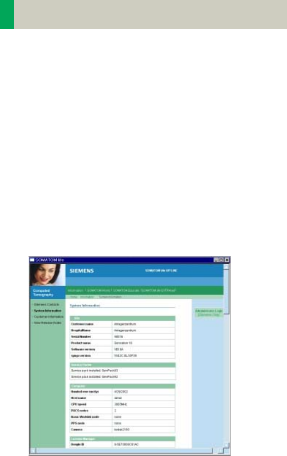
Description
All users:
Start SOMATOM life @ Your Scanner by selecting
SOMATOM life under "options" in your syngo menu bar
and you will find a browser window that allows you to
access different information about your hard- and soft-
ware environment.
Under e.g., "System Information" you have information
such as software version or scan second counter.
Under Customer Information you can enter your
demographic data.
Note: The institution data and at least one contact per-
son have to be entered to be able to access the Sie-
mens Extranet. The link to the Siemens Extranet will be
visible only after you have entered this data.
C2-025.630.01.01.02_APPLICATIONGUIDE_SPIRIT.book Page 56 Friday, April 8, 2005 9:55 AM
Application Information
57
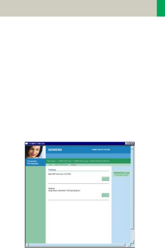
Access to Computer Based Training or Manuals on
CD ROM
Start the Computer Based Training to learn more about
your software and enhance your clinical knowledge.
Note: The syngo Basics Training is pre-installed on your
system and can directly be used by selecting SOMA-
TOM Educate. The syngo Advanced Application Train-
ing can be downloaded in the Siemens Extranet or is
sent to you automatically on CD if you request a trial
software via the Siemens Extranet.
In case a document (e.g., Application Guide) is not vis-
ible after being opened:
• Minimize or move the Browser window of the SOMA-
TOM life platform.
Under the navigation path "World" you can also start
your manual CD ROM.
C2-025.630.01.01.02_APPLICATIONGUIDE_SPIRIT.book Page 57 Friday, April 8, 2005 9:55 AM

58
Application Information
SRS Based Services
During the start up of your system you will receive
actual information in the "Newsticker" and see the
expiration date of installed trial software.
Note: Siemens will send you a Newsticker whenever
there is helpful information for CT users. The trial
licenses are valid for 90 days and can only be ordered
once.
Access the Siemens Extranet by clicking on "Extranet".
After entering your CT system serial number you will
be forwarded to the workspace. You can find the serial
number in the system information in the offline part of
SOMATOM life @ Your Scanner.
Now you have the ability to view information and use
the different services.
C2-025.630.01.01.02_APPLICATIONGUIDE_SPIRIT.book Page 58 Friday, April 8, 2005 9:55 AM
Application Information
59
Download of Files
Each download will be performed in the background. If
you disconnect your Siemens Extranet session and
start to work with the CT scanner, the download will
continue until it is completed. Due to bandwidth rea-
sons it is only possible to perform one download at a
time.
Note: Depending on your connection speed, the
download of larger files like e.g., the Advanced Appli-
cation Training may take a long time.
Downloaded files can be found in the "Offline" folder
which can be accessed under menu: Options/ File
Browser/ Offline.
After the download, the WBT will install itself and can
be started within the SOMATOM life offline part under
SOMATOM Educate.
C2-025.630.01.01.02_APPLICATIONGUIDE_SPIRIT.book Page 59 Friday, April 8, 2005 9:55 AM

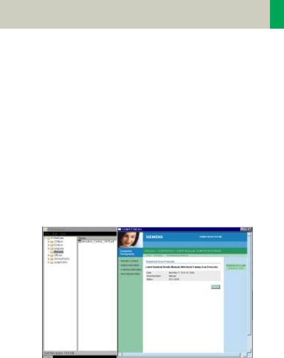
60
Application Information
Downloaded Scan Protocols are stored in the update
folder until installation. To install all downloaded pro-
tocols, choose the Scan Protocol Manager via Options/
Configuration and select "Import Scan Protocols" in the
menu tab "Scan Protocol". After successful import, all
downloaded protocols can be found under the name
that is stated in the Extranet in the "Siemens Folder".
Also, see the chapter Scan Protocol Manager for more
information.
Contact incl. DICOM Images
You are able to send emails to Siemens directly from
your scanner. For further explanation, even DICOM
images can be attached. To add an image, select the
images you want to send on your Viewing card and
export these images to H:\Offline as a DICOM image.
Also, see chapter "Export Function" for more informa-
tion.
After exporting the image, open the Siemens Extranet
and choose "Contact". After entering your message
you can easily attach the image by selecting the
images from the File Browser with the shortcut "CTRL"
and "C" and paste it with the shortcut "CTRL" and "P"
into the Extranet.
C2-025.630.01.01.02_APPLICATIONGUIDE_SPIRIT.book Page 60 Friday, April 8, 2005 9:55 AM

Application Information
61
Note: Every patient image will be made anonymous
before sending. Because the SOMATOM life window is
always in front, we recommend to restore/ minimize it
to be able to switch between both screens, the File
Browser and the SOMATOM life window.
C2-025.630.01.01.02_APPLICATIONGUIDE_SPIRIT.book Page 61 Friday, April 8, 2005 9:55 AM
62
Application Information
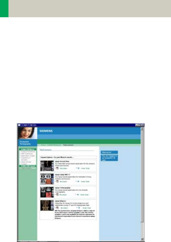
Trial Order and Installation
As a SOMATOM CT user you can request trial clinical
software directly from the scanner. The requested soft-
ware will be provided and installed automatically
through our Siemens Remote Services connection.
After you have accessed the SOMATOM life Extranet,
you can choose system specific trial software under
SOMATOM Expand. After clicking on "Order Trial" and
confirming a License Agreement for Trial-Use Soft-
ware, you need to enter your contact data. You can
then submit the license request.
C2-025.630.01.01.02_APPLICATIONGUIDE_SPIRIT.book Page 62 Friday, April 8, 2005 9:55 AM
Application Information
63
At the same time, you are informed that you can
expect the trial option to be installed within 8 working
days and you will then be informed about the success-
ful installation via the SOMATOM life message window
that appears during system start-up.
C2-025.630.01.01.02_APPLICATIONGUIDE_SPIRIT.book Page 63 Friday, April 8, 2005 9:55 AM
64
Application Information
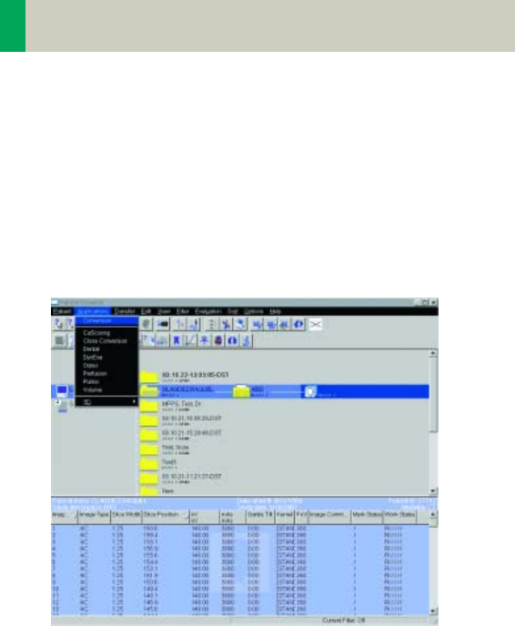
Image Converter
The CT Application Common DICOM Adapter provides
conversion between different DICOM data sets as they
may be provided by other CT vendors.
– You will find the converter in the Application menu
of the Patient Browser.
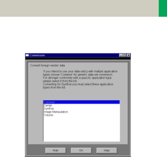
In the pop-up window you can select the application
for which you want to convert the images.
C2-025.630.01.01.02_APPLICATIONGUIDE_SPIRIT.book Page 64 Friday, April 8, 2005 9:55 AM
Application Information
65
After conversion you can load these data sets into the
application of your choice.
C2-025.630.01.01.02_APPLICATIONGUIDE_SPIRIT.book Page 65 Friday, April 8, 2005 9:55 AM

66
Application Information
File Browser
The File Browser provides the ability to access and to
manage your created files:
• Copy images and files to the CD Burn folder.
• Access to all created reports and movies (AVI files).
• Access to the offline folder.
• Access to downloaded files.
Open the File Browser via the main menu entry
"Options – File Browser".
The File Browser provides special folders for our Appli-
cations. Therein the created reports and movies are
saved.
With an external PC connected you can access your
offline data on the external PC for post-processing.
Transfer files to floppy:
– Select the desired files and send them via the right
mouse button menu on a floppy disk.
Burn on CD:
– Select the desired files and drag & drop them into the
folder “Burn on CD” (or send them via the right
mouse button menu to the folder “Burn on CD“).
– Open the “LocalJobStatus” in the Patient Browser and
clear all entries.
– Select “Record to Offline“ in the Transfer menu of the
Patient Browser.
–CD burning starts.
–Hint: CD burning of offline files is only possible in a
single session.
C2-025.630.01.01.02_APPLICATIONGUIDE_SPIRIT.book Page 66 Friday, April 8, 2005 9:55 AM

Application Information
67
Review reports and movies:
– Select the desired files and double-click on them.
– The corresponding program, e.g., Movie Media
Player will be opened and you can review what you
have saved.
– Now you can send these files to floppy or burn it on
CD.
Hint
• Files with the following extensions cannot be
started/ opened from the File Browser
“bat“, “cmd“, “com“, “exe“, “reg“, “dot“, “htm“,
“html“, “pl“, “vbs“, “js“, “wsf“, “wsh“, “xml“.
C2-025.630.01.01.02_APPLICATIONGUIDE_SPIRIT.book Page 67 Friday, April 8, 2005 9:55 AM

68
Application Information
Patient Protocol
Scan: number of scan range
kV: kilo Volt
mAs: averaged applied mAs of the range
ref. mAs: quality ref. mAs of the range
TI: Rotation Time
cSL: collimated Slice
CTDIvol: CTDIw
Pitch Factor
For further information please refer to
the chapter “Dose Information“.
DLP: Dose Length Product
CTDIvol x (length + collimated slice)
10
C2-025.630.01.01.02_APPLICATIONGUIDE_SPIRIT.book Page 68 Friday, April 8, 2005 9:55 AM

Application Information
69
C2-025.630.01.01.02_APPLICATIONGUIDE_SPIRIT.book Page 69 Friday, April 8, 2005 9:55 AM
70
Head
Overview
–HeadRoutine
Spiral mode for base of the skull and cerebrum rou-
tine studies
–HeadSeq
Sequential mode for base of the skull and cerebrum
routine studies
–InnerEarHR
Spiral mode for inner ear studies with a high resolu-
tion kernel
–InnerEarSeqHR
Sequence mode for inner ear studies with a high res-
olution kernel
–Sinus
Spiral mode for sinus studies
–SinusSeq
Sequence mode for sinus studies
–Orbita
Spiral mode for orbital studies
–Dental
Spiral mode for dental studies
C2-025.630.01.01.02_APPLICATIONGUIDE_SPIRIT.book Page 70 Friday, April 8, 2005 9:55 AM

Head
71
Hints in General
• Topogram: Lateral, 256 mm.
• Patient positioning:
Patient lying in supine position, arms resting against
body, secure head well in the head holder, support
lower legs.
• Gantry tilt is available for both, sequence and spiral
scanning.
However, image artifacts may occur if spirals are
acquired with a tilt angle greater than 8°.
• For all head studies, it is very important for image
quality to position the patient in the center of the
scan field. Use the lateral laser beam to make sure
that the patient is positioned in the center.
• In order to optimize image quality versus radiation
dose, scans are provided within a maximum scan
field of 300 mm with respect to the iso-center. No
recon job with a field of view exceeding those limits
will be possible. Therefore, patient positioning has to
be performed accurately to ensure a centered loca-
tion of the skull.
Head Kernels
• For soft tissue head studies, the standard kernel is
H41s; softer images are obtained with H31s or H21s
sharper images with H50s.
• High resolution head studies should be performed
with H60s, H70s (e.g., for dental and sinuses) and
H80s (e.g., inner ear).
C2-025.630.01.01.02_APPLICATIONGUIDE_SPIRIT.book Page 71 Friday, April 8, 2005 9:55 AM

72
Head
HeadRoutine
Indications:
Spiral mode for routine head studies, e.g., stroke, brain
tumors, cranial trauma, cerebral atrophy, hydroceph-
alus, and inflammation, etc.
Two ranges are predefined for the base of the skull and
cerebrum.
A range for the base of 4 cm will be covered in 23 sec.,
a range for the cerebrum of 8 cm will be covered in
27 sec.
C2-025.630.01.01.02_APPLICATIONGUIDE_SPIRIT.book Page 72 Friday, April 8, 2005 9:55 AM

Head
73
Hints
• An automatic bone correction allows for improved
head image quality, without any additional post-pro-
cessing.
• In order to optimize image quality versus radiation
dose, scans are provided within a maximum scan
field of 300 mm with respect to the iso-center. No
recon job with a field of view exceeding those limits
will be possible. Therefore, patient positioning has to
be performed accurately to ensure a centered loca-
tion of the skull.
Base Cerebrum
kV 130 130
Effective mAs 110 110
Rotation time 1.5 sec 1.5 sec
Slice collimation 1.5 mm 2.5 mm
Slice width 3.0 mm 8.0 mm
Feed/Rotation 3.0 mm 5.0 mm
Pitch Factor 1.0 1.0
Increment 3.0 mm 8.0 mm
Kernel H31s H31s
CTDIVol 25.05 mGy 25.05 mGy
Effective dose Male:
0.37 mSv
Female:
0.38 mSv
Male:
0.70 mSv
Female:
0.77 mSv
Contrast medium IV injection
Volume 50 – 60 ml
Flow rate 2 ml/sec.
Start delay 50 – 60 sec.
C2-025.630.01.01.02_APPLICATIONGUIDE_SPIRIT.book Page 73 Friday, April 8, 2005 9:55 AM
74
Head
HeadSeq
Indications:
Sequence mode for routine head studies, e.g., stroke,
brain tumors, cranial trauma, cerebral atrophy, hydro-
cephalus, and inflammation, etc.
Two ranges are predefined. One for the base of the
skull and one for the cerebrum, the scan length for the
entire head is 12.4 mm.
For both ranges a typical gantry tilt of -20° is pre-
defined.
C2-025.630.01.01.02_APPLICATIONGUIDE_SPIRIT.book Page 74 Friday, April 8, 2005 9:55 AM

Head
75
Hints
• An automatic bone correction allows for improved
head image quality, without any additional post-pro-
cessing.
• In order to optimize image quality versus radiation
dose, scans are provided within a maximum scan
field of 300 mm with respect to the iso-center. No
recon job with a field of view exceeding those limits
will be possible. Therefore, patient positioning has to
be performed accurately to ensure a centered loca-
tion of the skull.
BaseSeq CerebrumSeq
kV 130 130
Effective mAs 240 240
Rotation time 1.5 sec 1.5 sec
Slice collimation 1.5 mm 4.0 mm
Slice width 3.0 mm 8.0 mm
Feed/Scan 3.0 mm 8.5 mm
Kernel H31s H31s
CTDIVol 54.65 mGy 51.43 mGy
Effective dose Male:
0.77 mSv
Female:
0.80 mSv
Male: 1.52 mSv
Female:
1.68 mSv
Contrast medium IV injection
Start delay 60 sec.
Flow rate 2 ml/sec.
Volume 50 – 60 ml
C2-025.630.01.01.02_APPLICATIONGUIDE_SPIRIT.book Page 75 Friday, April 8, 2005 9:55 AM

76
Head
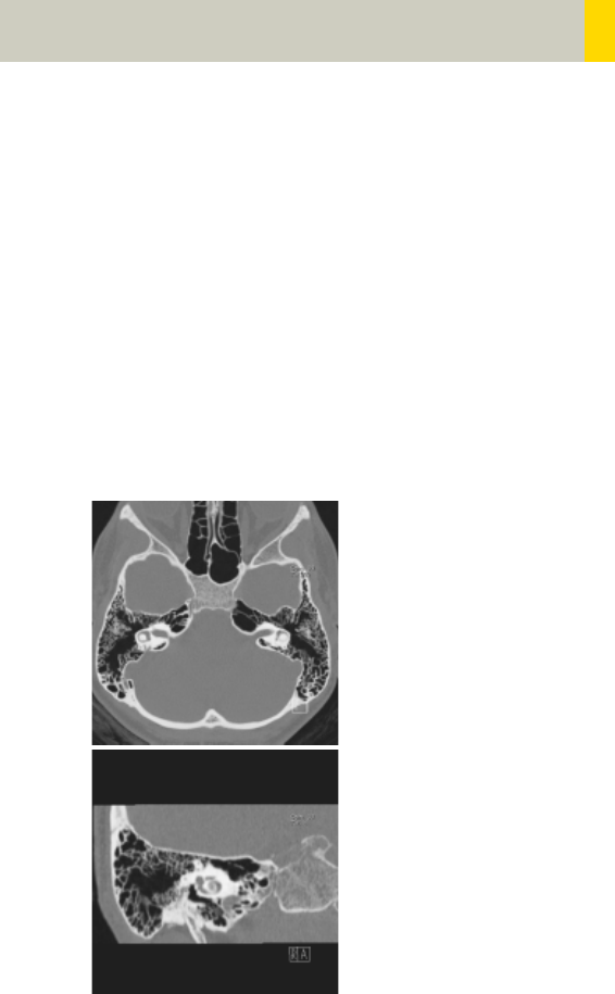
InnerEarHR
Indications:
Spiral mode for inner ear High Resolution studies, e.g.,
inflammatory changes, tumorous processes of pyra-
mids, cerebellopontine angle tumors, post-traumatic
changes, etc.
A range of 2.5 cm will be covered in 22 sec.
InnerEar 2nd reconstr.
kV 130
Effective mAs 70
Rotation time 1.5 sec
Slice collimation 1.0 mm
Slice width 2.0 mm 1.25 mm
Feed/Rotation 2.0 mm
Pitch Factor 1.0
Increment 2.0 mm 0.8 mm
Kernel H80s H80s
CTDIVol 15.94 mGy
Effective dose Male: 0.17 mSv
Female: 0.20 mSv
C2-025.630.01.01.02_APPLICATIONGUIDE_SPIRIT.book Page 76 Friday, April 8, 2005 9:55 AM
Head
77
Hints
• For image reconstruction of soft tissue, use kernel
H31s.
• An automatic bone correction allows for improved
head image quality, without any additional post-pro-
cessing.
• In order to optimize image quality versus radiation
dose, scans are provided within a maximum scan
field of 300 mm with respect to the iso-center. No
recon job with a field of view exceeding those limits
will be possible. Therefore, patient positioning has to
be performed accurately to ensure a centered loca-
tion of the skull.
C2-025.630.01.01.02_APPLICATIONGUIDE_SPIRIT.book Page 77 Friday, April 8, 2005 9:55 AM
78
Head
InnerEarHRSeq
Indications:
Sequential mode for inner ear studies, e.g., inflamma-
tory changes, tumorous processes of pyramids, cere-
bellopontine angle tumors, post-traumatic changes,
etc.
A typical gantry tilt of -20 degree is predefined. A
range of 2.5 cm will be covered.
InnerEarSeq
kV 130
Effective mAs 140
Rotation time 1.5 sec
Slice collimation 1.0 mm
Slice width 1.0 mm
Feed/Scan 2.0 mm
Kernel H80s
CTDIVol 31.88 mGy
Effective dose Male: 0.32 mSv
Female: 0.38 mSv
Contrast medium IV injection
Start delay 60 sec.
Flow rate 2 ml/sec.
Total amount 50 – 60 ml
C2-025.630.01.01.02_APPLICATIONGUIDE_SPIRIT.book Page 78 Friday, April 8, 2005 9:55 AM

Head
79
Hints
• For image reconstruction of soft tissue, use kernel
H31s.
• An automatic bone correction allows for improved
head image quality, without any additional post-pro-
cessing.
• In order to optimize image quality versus radiation
dose, scans are provided within a maximum scan
field of 300 mm with respect to the iso-center. No
recon job with a field of view exceeding those limits
will be possible. Therefore, patient positioning has to
be performed accurately to ensure a centered loca-
tion of the skull.
C2-025.630.01.01.02_APPLICATIONGUIDE_SPIRIT.book Page 79 Friday, April 8, 2005 9:55 AM

80
Head
Sinus
Indications:
Spiral mode for paranasal sinuses studies, e.g., sinusi-
tis, mucocele, pneumatization, polyposis, tumor, cor-
rections etc.
A range of 7 cm will be covered in 37 sec.
Sinus 2nd reconstr.
kV 130
Effective mAs 60
Rotation time 1.0 sec
Slice collimation 1.0 mm
Slice width 3.0 mm 1.25 mm
Feed/Rotation 2.0 mm
Pitch Factor 1.0
Increment 3.0 mm 0.8 mm
Kernel H70s H70s
CTDIVol 13.66 mGy
Effective dose Male: 0.21 mSv
Female: 0.22 mSv
Contrast medium IV injection
Start delay 60 sec
Flow rate 2 ml/sec
Total amount 50 – 60 ml
C2-025.630.01.01.02_APPLICATIONGUIDE_SPIRIT.book Page 80 Friday, April 8, 2005 9:55 AM

Head
81
Hints
• An automatic bone correction and an advanced algo-
rithm allows for improved head image quality, with-
out any additional post-processing.
• In order to optimize image quality versus radiation
dose, scans are provided within a maximum scan
field of 300 mm with respect to the iso-center. No
recon job with a field of view exceeding those limits
will be possible. Therefore, patient positioning has to
be performed accurately to ensure a centered loca-
tion of the skull.
• For image reconstruction of soft tissue, use kernel
H31s.
C2-025.630.01.01.02_APPLICATIONGUIDE_SPIRIT.book Page 81 Friday, April 8, 2005 9:55 AM

82
Head
SinusSeq
Indications:
Sequential mode for paranasal sinuses studies, e.g.,
sinusitis, mucocele, pneumatization, polyposis, tumor,
corrections etc.
A range of 4.2 cm will be covered.
SinusSeq
kV 130
Effective mAs 120
Rotation time 1.0 sec
Slice collimation 1.5 mm
Slice width 3.0 mm
Feed/Scan 3.0 mm
Kernel H70s
CTDIVol 27.32 mGy
Effective dose Male: 0.22 mSv
Female: 0.24 mSv
Contrast medium IV injection
Start delay 60 sec
Flow rate 2 ml/sec
Total amount 50 – 60 ml
C2-025.630.01.01.02_APPLICATIONGUIDE_SPIRIT.book Page 82 Friday, April 8, 2005 9:55 AM

Head
83
Hints
• An automatic bone correction and an advanced algo-
rithm allows for improved head image quality, with-
out any additional post-processing.
• In order to optimize image quality versus radiation
dose, scans are provided within a maximum scan
field of 300 mm with respect to the iso-center. No
recon job with a field of view exceeding those limits
will be possible. Therefore, patient positioning has to
be performed accurately to ensure a centered loca-
tion.
• For image reconstruction of soft tissue, use kernel
H31s.
C2-025.630.01.01.02_APPLICATIONGUIDE_SPIRIT.book Page 83 Friday, April 8, 2005 9:55 AM

84
Head
Orbita
Indications:
Spiral mode for orbital studies, e.g., fracture.
A range of 2 cm will be covered in 12 sec.
Orbita 2nd reconstr.
kV 130
Effective mAs 100
Rotation time 1.0 sec
Slice collimation 1.0 mm
Slice width 3.0 mm 1.25 mm
Feed/Rotation 2.0 mm
Pitch Factor 1.0
Increment 3.0 mm 0.8 mm
Kernel H70s H70s
CTDIVol 22.77 mGy
Effective dose Male:
0.10 mSv
Female:
0.11 mSv
Contrast medium IV injection
Start delay 60 sec
Flow rate 2 ml/sec
Volume 50 – 60 ml
C2-025.630.01.01.02_APPLICATIONGUIDE_SPIRIT.book Page 84 Friday, April 8, 2005 9:55 AM

Head
85
Hints
• An automatic bone correction and an advanced algo-
rithm allows for improved head image quality, with-
out any additional post-processing.
• In order to optimize image quality versus radiation
dose, scans are provided within a maximum scan
field of 300 mm with respect to the iso-center. No
recon job with a field of view exceeding those limits
will be possible. Therefore, patient positioning has to
be performed accurately to ensure a centered loca-
tion of the skull.
• For image reconstruction of soft tissue, use kernel
H31s.
C2-025.630.01.01.02_APPLICATIONGUIDE_SPIRIT.book Page 85 Friday, April 8, 2005 9:55 AM

86
Head
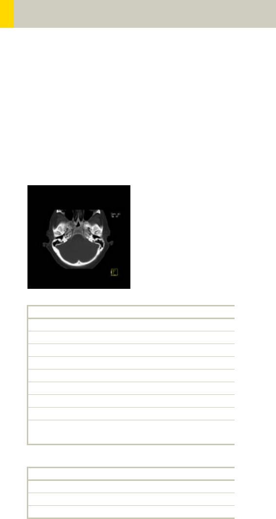
Dental
This is the scan protocol for the syngo Dental CT appli-
cation package. It is used for evaluation and reformat-
ting of the upper and lower jaws.
It enables the display and measurement of the bone
structures of the upper and lower jaw as the basis for
planning in oral surgery.
Indications:
Spiral mode for dental studies.
A range of 5 cm will be covered in 27 sec.
Load the study into the application “syngo Dental CT”.
For further information, please refer to the chapter
"syngo Dental CT".
Dental
kV 130
Effective mAs 45
Rotation time 1.0 sec
Slice collimation 1.0 mm
Slice width 1.25 mm
Feed/Rotation 2.0 mm
Pitch Factor 1.0
Increment 0.5 mm
Kernel H60s
CTDIVol 10.25 mGy
Effective dose Male: 0.13 mSv
Female: 0.16 mSv
C2-025.630.01.01.02_APPLICATIONGUIDE_SPIRIT.book Page 86 Friday, April 8, 2005 9:55 AM

Head
87
C2-025.630.01.01.02_APPLICATIONGUIDE_SPIRIT.book Page 87 Friday, April 8, 2005 9:55 AM
88
Neck
Overview
–Neck
Spiral mode for soft tissue routine neck studies
C2-025.630.01.01.02_APPLICATIONGUIDE_SPIRIT.book Page 88 Friday, April 8, 2005 9:55 AM

Neck
89
Hints in General
• Topogram: Lateral, 256 mm
• Patient positioning
Patient lying in supine position, hyperextend neck
slightly, secure head well in head holder.
• Patient respiratory instruction:
do not breathe, do not swallow.
• For contrast studies, CARE Bolus may be used to opti-
mize the bolus timing.
• For image reconstruction of bone structures, use ker-
nel B60.
C2-025.630.01.01.02_APPLICATIONGUIDE_SPIRIT.book Page 89 Friday, April 8, 2005 9:55 AM

90
Neck
Body Kernels
• As standard kernels for body tissue studies B31s or
B41s are recommended; softer images are obtained
with B20s.
• For higher sharpness, as is required e.g., in patient
protocols for cervical spine, shoulder, extremities,
thorax, the kernels B50s, B60s, B70s are available.
• In case of 3D study only, use kernel B20s and at least
50% overlapping for image reconstruction.
Patient positioning is very important for artifact-free
images. The thoracic girdle should be positioned as far
as possible in the caudal direction. This can be done
using a strap with a permanent loop or Velcro fastener
at its end. The ends of the strap must be attached to
the patients wrists. Then the strap must be wrapped
around the patients feet with his legs extended and
under tension. The entire thoracic girdle is thus pulled
toward the patients feet.
C2-025.630.01.01.02_APPLICATIONGUIDE_SPIRIT.book Page 90 Friday, April 8, 2005 9:55 AM

Neck
91
C2-025.630.01.01.02_APPLICATIONGUIDE_SPIRIT.book Page 91 Friday, April 8, 2005 9:55 AM

92
Neck
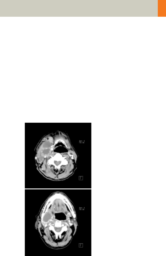
Neck
Indications:
For soft tissue spiral studies in the cervical region, e.g.,
tumors, lymphoma, abscesses etc.
A typical range of 20 cm will be covered in 42 sec.
Neck
kV 130
Effective mAs 70
Rotation time 1.0 sec
Slice collimation 2.5 mm
Slice width 5.0 mm
Feed/Rotation 5.0 mm
Pitch Factor 1.0
Increment 5.0 mm
Kernel B50s
CTDIVol 7.55 mGy
Effective dose Male: 1.79 mSv
Female: 1.87 mSv
Contrast medium IV injection
Start delay 45 sec.
Flow rate 2.0 ml/sec.
Total amount 120 ml
C2-025.630.01.01.02_APPLICATIONGUIDE_SPIRIT.book Page 92 Friday, April 8, 2005 9:55 AM
Neck
93
Hints
• Due to its iodine content, the thyroid gland is hyper-
dense in relation to the neighboring muscles both
before and after an IV CM injection. For displays of
the parotid, thyroid or the floor of the mouth, the
slice thickness should be < 5 mm and the length of
the range should be adapted to match the anatomic
region.
• Target the FoV to ensure adequate coverage of the
region of interest in the upper neck & middle neck
levels as well as to include the axilla in the lower
neck level if required.
C2-025.630.01.01.02_APPLICATIONGUIDE_SPIRIT.book Page 93 Friday, April 8, 2005 9:55 AM
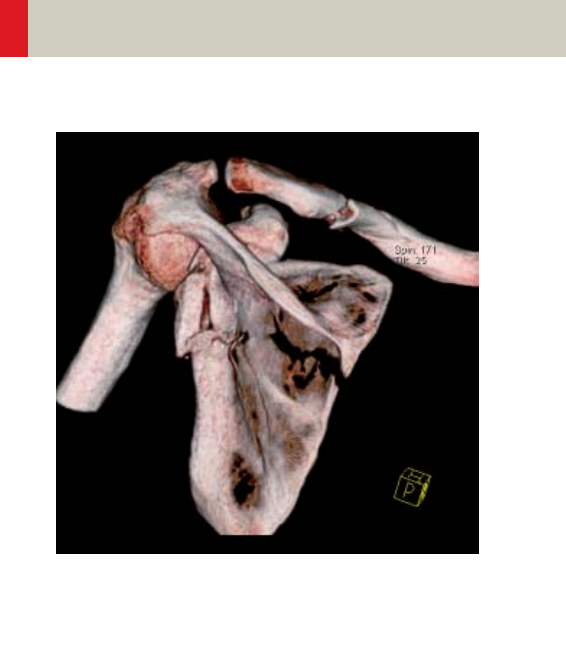
94
Shoulder
Overview
–Shoulder
Spiral mode for bone shoulder routine studies
C2-025.630.01.01.02_APPLICATIONGUIDE_SPIRIT.book Page 94 Friday, April 8, 2005 9:55 AM

Shoulder
95
Hints in General
• Topogram: TOP, 256 mm.
• Patient positioning:
Patient lying in supine position, the uninjured arm
placed above the head, the injured arm placed flat
against his body. Position side under examination in
the center and support the other side with a Bocollo
pillow.
• If only one side is examined, it is advisable to enter
the side examined in the comment line.
• Contrast medium is required for soft tissue mass
evaluation.
• To further optimize MPR image quality, we recom-
mend that you reduce one or more of the following
parameters: collimation, reconstruction increment,
and slice width for image reconstruction.
Body Kernels
• As standard kernels for body tissue studies B31s or
B41s are recommended; softer images are obtained
with B20s.
• For higher sharpness, as is required e.g., in patient
protocols for cervical spine, shoulder, extremities,
thorax, lung, the kernels B50s, B60s, B70s are avail-
able.
C2-025.630.01.01.02_APPLICATIONGUIDE_SPIRIT.book Page 95 Friday, April 8, 2005 9:55 AM
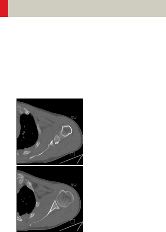
96
Shoulder
Shoulder
Indications:
Spiral mode for bone studies and soft tissue, e.g., eval-
uation of joint cavities, masses, trauma, dislocations,
orthopedic indications etc.
A scan range of 10 cm will be covered in 35 sec.
C2-025.630.01.01.02_APPLICATIONGUIDE_SPIRIT.book Page 96 Friday, April 8, 2005 9:55 AM

Shoulder
97
Hints
• Use raw data to review a target region if necessary.
• For image reconstruction of soft tissue, use kernel
B31s and a slice width of 5.0 mm.
• Coronal and sagittal 2D planar reconstructions are
important for evaluation of the joint space & bursa
sacs in CT arthograms.
• 3D renderings are helpful for complex fractures &
dislocations.
Shoulder 2nd reconstruction
kV 130
Effective mAs 70
Rotation time 1.0 sec
Slice
collimation
1.5 mm
Slice width 3.0 mm 2.0 mm
Feed/Rotation 3.0 mm
Pitch Factor 1.0
Increment 3.0 mm 1.5 mm
Kernel B60s
CTDIVol 7.55 mGy
Effective dose Male:
0.94 mSv
Female:
1.13 mSv
C2-025.630.01.01.02_APPLICATIONGUIDE_SPIRIT.book Page 97 Friday, April 8, 2005 9:55 AM
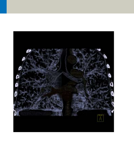
98
Thorax
Overview
–ThoraxRoutine/ThoraxRoutine08s
Spiral mode for routine chest studies
–ThoraxFast
Spiral mode for fast chest studies
–ThoraxHRSeq
Sequential mode for high resolution lung studies
–LungLowDose
Spiral mode with very low dose for early visualiza-
tion of pathologies
C2-025.630.01.01.02_APPLICATIONGUIDE_SPIRIT.book Page 98 Friday, April 8, 2005 9:55 AM

Thorax
99
Hints in General
• Topogram: TOP, 512 mm.
• Patient positioning: Patient lying in supine position,
arms positioned comfortably above the head in the
head-arm rest, lower legs supported.
• Contrast medium administration: in general, IV
injections are employed in all mediastinal examina-
tions, but not in routine high resolution studies of
diffuse interstitial lung diseases. An IV contrast
medium injection improves the vascular opacifica-
tion and facilitates the visualization of the lesions,
lymph nodes and the vessels.
• Stasis of contrast medium in the arm & superior vena
cava often result in high density streak artifacts
either in the region of the aortic arch or in the region
of the subclavian vein. A caudo-cranial (bottom to
top) scanning direction should be used to reduce this
artifact – by simply acquiring the data in this region
at the later phase of the spiral scan. In addition, if the
patient cannot hold his/her breath for the duration of
the entire scan, breathing motion will be less appar-
ent in the apex than in the lower lobes.
• CARE Bolus may be used to optimize the bolus tim-
ing. Set the ROI for monitoring scan in the aorta at
the level of the diaphragm with triggering threshold
of 120 HU, or use manual triggering.
C2-025.630.01.01.02_APPLICATIONGUIDE_SPIRIT.book Page 99 Friday, April 8, 2005 9:55 AM

100
Thorax
• Lung images should be documented in both soft tis-
sue window and lung window.
• It is also possible to interleave the soft tissue & lung
setting images in one film sheet. This can be set up
in the configuration for filming.
• To further optimize MPR image quality, we recom-
mend that you reduce one or more of the following
parameters: collimation, reconstruction increment,
and slice width for image reconstruction.
C2-025.630.01.01.02_APPLICATIONGUIDE_SPIRIT.book Page 100 Friday, April 8, 2005 9:55 AM

Thorax
101
Body Kernels
• As standard kernels for body tissue studies B31s or
B41s are recommended; softer images are obtained
with B20s.
• For higher sharpness, as is required e.g., in patient
protocols for cervical spine, shoulder, extremities,
thorax, the kernels B50s, B60s, B70s are available.
C2-025.630.01.01.02_APPLICATIONGUIDE_SPIRIT.book Page 101 Friday, April 8, 2005 9:55 AM
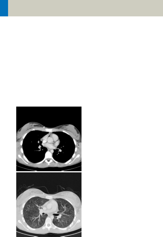
102
Thorax
ThoraxRoutine/
ThoraxRoutine08s
Indications:
Routine spiral studies for the region of thorax, e.g.,
examination of tumors, metastases, lymphoma, lymph
nodes, vascular anomalies etc.
A range of 30 cm will be covered in 23/18 sec.
C2-025.630.01.01.02_APPLICATIONGUIDE_SPIRIT.book Page 102 Friday, April 8, 2005 9:55 AM

Thorax
103
Hints
• You could repeat the same protocol by simply click-
ing the chronicle with the right mouse button for
“repeat“, e.g., when both non-contrast and contrast
studies are required.
• For lung cancer evaluation, this protocol can be com-
bined with the protocol “Neck Routine”.
ThorRoutine 2nd
reconstruction
kV 130
Effective mAs 60
Rotation time 0.8/1.0 sec
Slice
collimation
4.0 mm
Slice width 5.0 mm 5.0 mm
Feed/Rotation 14.4 mm
Pitch Factor 1.8
Increment 5.0 mm 5.0 mm
Kernel B41s B70s
CTDIVol 6.47 mGy
Effective dose Male:
3.28 mSv
Female:
4.23 mSv
Contrast medium IV injection
Start delay 25 – 30 sec.
Flow rate 2.5 ml/sec.
Total amount 80 ml
C2-025.630.01.01.02_APPLICATIONGUIDE_SPIRIT.book Page 103 Friday, April 8, 2005 9:55 AM
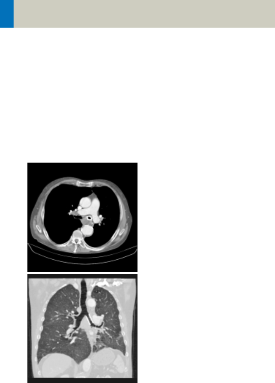
104
Thorax
ThoraxFast
Indications:
Fast spiral mode for lung studies, e.g., when a patient
has difficulty with breathhold.
A complete thorax scan in a range of 30 cm will be cov-
ered in 14 sec.
C2-025.630.01.01.02_APPLICATIONGUIDE_SPIRIT.book Page 104 Friday, April 8, 2005 9:55 AM

Thorax
105
Hints
• You could repeat the same protocol by simply click-
ing the chronicle with the right mouse button for
“repeat“, e.g., when both non-contrast and contrast
studies are required.
• For lung cancer evaluation, this protocol can be com-
bined with the protocol “Neck Routine”.
ThorFast 2nd reconstr.
kV 130
Effective mAs 60
Rotation time 0.8 sec
Slice collimation 5.0 mm
Slice width 8.0 mm 8.0 mm
Feed/Rotation 20.0 mm
Pitch Factor 2.0
Increment 8.0 mm 8.0 mm
Kernel B41s B70s
CTDIVol 6.47 mGy
Effective dose Male:
3.38 mSv
Female:
4.39 mSv
Contrast medium IV injection
Start delay 25 – 30 sec.
Flow rate 2.5 ml/sec.
Total amount 80 ml
C2-025.630.01.01.02_APPLICATIONGUIDE_SPIRIT.book Page 105 Friday, April 8, 2005 9:55 AM
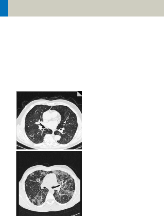
106
Thorax
ThoraxHRSeq
Indications:
Sequence mode for HiRes lung studies, e.g., interstitial
changes in the lungs.
Images are acquired with a range of 30.1 cm.
C2-025.630.01.01.02_APPLICATIONGUIDE_SPIRIT.book Page 106 Friday, April 8, 2005 9:55 AM

Thorax
107
Hints
• If you want to reconstruct thin slices every 15 or
20 mm instead of 10 mm as predefined, simply
change the Feed/Scan before loading the mode.
• With studies of interstitial changes in the lungs, con-
trast medium is not necessary.
ThorHRSeq
kV 130
Effective mAs 100
Rotation time 1.0 sec
Slice collimation 1.0 mm
Slice width 1.0 mm
Feed/Scan 10.0 mm
Kernel U90s
CTDIVol 2.16 mGy
Effective dose Male: 1.02 mSv
Female: 1.33 mSv
C2-025.630.01.01.02_APPLICATIONGUIDE_SPIRIT.book Page 107 Friday, April 8, 2005 9:55 AM
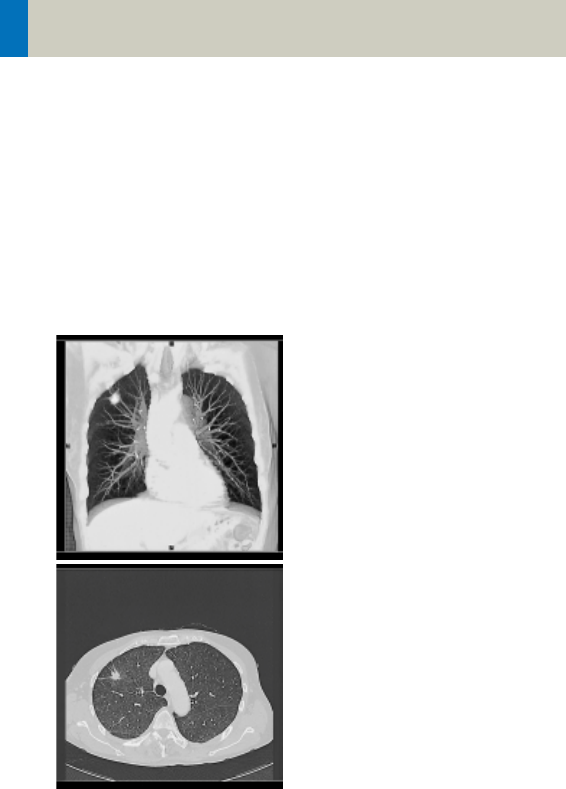
108
Thorax
LungLowDose
Indications:
Spiral lung studies with low dose setting, e.g., early
visualization of pulmonary nodules.
A typical thorax study in a range of 30 cm will be cov-
ered in 32 sec.
C2-025.630.01.01.02_APPLICATIONGUIDE_SPIRIT.book Page 108 Friday, April 8, 2005 9:55 AM

Thorax
109
Hints
• You could repeat the same protocol by simply click-
ing the chronicle with the right mouse button for
“repeat“, e.g., when both non-contrast and contrast
studies are required.
• For lung cancer evaluation, this protocol can be com-
bined with the protocol “Neck Routine”.
• Low dose lung images are usually evaluated using
lung window setting. Soft tissue/bone window set-
tings may be used to visualize the presence of calci-
fications in the nodules.
• It is essential to use the same protocol for follow-up
studies to check for progression.
LungLowDose
kV 130
Effective mAs 30
Rotation time 1.0 sec
Slice collimation 5.0 mm
Slice width 8.0 mm
Feed/Rotation 10.0 mm
Pitch Factor 1.0
Increment 8.0 mm
Kernel B70s
CTDIVol 3.23 mGy
Effective dose Male: 1.69 mSv
Female: 2.08 mSv
Contrast medium IV injection
Start delay 30 sec.
Flow rate 2.5 ml/sec.
Total amount 50 – 70 ml
C2-025.630.01.01.02_APPLICATIONGUIDE_SPIRIT.book Page 109 Friday, April 8, 2005 9:55 AM
110
Abdomen
Overview
–AbdomenRoutine/AbdomenRoutine08s
Spiral mode for routine abdominal studies
–AbdomenFast
Spiral mode for fast abdominal studies
–AbdMultiPhase/AbdMultiPhase08s
Spiral mode for three-phase liver studies
–AbdomenSeq
Sequential mode for abdominal studies
C2-025.630.01.01.02_APPLICATIONGUIDE_SPIRIT.book Page 110 Friday, April 8, 2005 9:55 AM

Abdomen
111
Hints in General
• Topogram: TOP, 512.
• Patient positioning:
Patient lying in supine position, arms positioned
comfortably above the head in the head-arm rest,
lower legs supported.
• Patient respiratory instruction: Inspiration.
• Oral administration of contrast medium:
For abdominal studies, it is necessary to delineate
the bowel from other structures such as lymph
nodes, abdominal masses & abscesses. Various types
of bowel opacifying agents can be used:
- Diluted barium suspension (1% – 2%) e.g., EZCAT
- Water soluble agent (2% – 4%) e.g., Gastrografin
- Water alone, as a negative contrast agent.
Timing of the oral contrast administration is impor-
tant to ensure its even distribution in the bowel.
Upper abdomen:
Minimum 600 ml of contrast divided into 3 cups
(approximately 200 – 250 ml)
1st cup to drink 30 minutes before exam
2nd cup to drink 15 minutes before exam
3rd cup to drink 5 minutes before exam
Abdomen – Pelvis:
Minimum 1000 ml of contrast divided into 4 cups
1st cup to drink 1hour before exam
2nd–4th cups every subsequent 15 minutes
Start exam 5 minutes after the 4th cup is adminis-
tered.
C2-025.630.01.01.02_APPLICATIONGUIDE_SPIRIT.book Page 111 Friday, April 8, 2005 9:55 AM

112
Abdomen
• In general, for abdominal studies such as liver, gall
bladder (query stones), pancreas, gastrointestinal
studies, focal lesion of the kidneys and CTA studies,
it is sufficient to use just water. Water is more effec-
tive than positive oral contrast agent in depicting the
linings of the stomach & intestines in post enhance-
ment studies. In addition, the use of water will not
obscure the blood vessels thus allowing CTA process-
ing to be performed easily afterwards.
• For patients with bowel obstruction, only water or
water-soluble contrast can be used. Barium suspen-
sion is contraindicated.
• Be careful when examining pheochromocytoma
patients. Administration of an IV CM injection in
such cases may trigger a hypertensive crisis!
• To further optimize MPR image quality, we recom-
mend that you reduce one or more of the following
parameters: collimation, reconstruction increment,
and slice width for image reconstruction.
• For abdominal studies deselect CARE Dose for
patients > 120 kg.
C2-025.630.01.01.02_APPLICATIONGUIDE_SPIRIT.book Page 112 Friday, April 8, 2005 9:55 AM

Abdomen
113
Body Kernels
• As standard kernels for body tissue studies B31s or
B41s are recommended; softer images are obtained
with B20s.
• For higher sharpness, as is required e.g., in patient
protocols for cervical spine, shoulder, extremities,
thorax, lung, the kernels B50s, B60s, B70s are avail-
able.
C2-025.630.01.01.02_APPLICATIONGUIDE_SPIRIT.book Page 113 Friday, April 8, 2005 9:55 AM
114
Abdomen
AbdomenRoutine/
AbdomenRoutine08s
Indications:
Spiral mode for all routine studies in the region of
abdomen, e.g., evaluation, follow-up examinations
etc.
A typical abdomen scan in a range of 20 cm will be
covered in 16/13 sec.
C2-025.630.01.01.02_APPLICATIONGUIDE_SPIRIT.book Page 114 Friday, April 8, 2005 9:55 AM

Abdomen
115
Hints
• You could repeat the same protocol by simply click-
ing the chronicle with the right mouse button for
“repeat“, e.g., when both non-contrast and contrast
studies are required.
• Delayed scans may be required for the kidneys &
bladder.
AbdRoutine
kV 130
Effective mAs 60
Rotation time 0.8/1.0 sec
Slice collimation 4.0 mm
Slice width 5.0 mm
Feed/Rotation 14.4 mm
Pitch Factor 1.8
Increment 5.0 mm
Kernel B41s
CTDIVol 6.47 mGy
Effective dose Male: 2.61 mSv
Female: 3.32 mSv
Contrast medium IV injection
Start delay 50 – 60 sec.
Flow rate 1.0 – 2.0 ml/sec.
Total amount 100 ml
C2-025.630.01.01.02_APPLICATIONGUIDE_SPIRIT.book Page 115 Friday, April 8, 2005 9:55 AM
116
Abdomen
AbdomenFast
Indications:
Fast spiral mode for abdominal studies, e.g., when a
patient has difficulty with holding their breath.
A range of 20 cm will be covered in 9.6 sec.
C2-025.630.01.01.02_APPLICATIONGUIDE_SPIRIT.book Page 116 Friday, April 8, 2005 9:55 AM

Abdomen
117
Hint
• You could repeat the same protocol by simply click-
ing the chronicle with the right mouse button for
“repeat“, e.g., when both non-contrast and contrast
studies are required.
AbdFast
kV 130
Effective mAs 60
Rotation time 0.8 sec
Slice collimation 5.0 mm
Slice width 8.0 mm
Feed/Rotation 20.0 mm
Pitch Factor 2.0
Increment 8.0 mm
Kernel B41s
CTDIVol 6.47 mGy
Effective dose Male: 2.59 mSv
Female: 3.29 mSv
Contrast medium IV injection
Start delay 25 – 30 sec.
Flow rate 2.5 ml/sec.
Total amount 80 ml
C2-025.630.01.01.02_APPLICATIONGUIDE_SPIRIT.book Page 117 Friday, April 8, 2005 9:55 AM
118
Abdomen
AbdMultiPhase/
AbdMultiPhase08s
Indications:
Spiral scan to assist the physician with differential
diagnosis of liver diseases.
A typical native range of 20 cm will be covered in
15 sec.
C2-025.630.01.01.02_APPLICATIONGUIDE_SPIRIT.book Page 118 Friday, April 8, 2005 9:55 AM

Abdomen
119
* CARE Bolus may be used to optimize the bolus tim-
ing. Set the ROI for monitoring scan in the abdominal
aorta at the beginning of the scan range with trigger-
ing threshold of 120 HU, or use manual triggering.
Non
Contrast
Arterial
Phase
Venous
Phase
kV 130 130 130
Effective mAs 80 80 80
Rotation time 1.0 sec 0.8/1.0
sec
1.0 sec
Slice
collimation
5.0 mm 5.0 mm 5.0 mm
Slice width 8.0 mm 6.0 mm 6.0 mm
Feed/Rotation 15.0 mm 14.0/
15.0 mm
15.0 mm
Pitch Factor 1.5 1.4/1.5 1.5
Increment 8.0 mm 6.0 mm 6.0 mm
Kernel B41s B41s B41s
CTDIVol 8.62 mGy 8.62 mGy 8.62 mGy
Effective dose Male:
3.34 mSv
Female:
4.19 mSv
Male:
3.34 mSv
Female:
4.19 mSv
Male:
3.34 mSv
Female:
4.19 mSv
Contrast medium IV injection
Start delay 20 – 25 sec.* (arterial phase)
50 – 75 sec.* (venous phase)
Flow rate 3.0 ml/sec.
Total amount 100 ml
C2-025.630.01.01.02_APPLICATIONGUIDE_SPIRIT.book Page 119 Friday, April 8, 2005 9:55 AM

120
Abdomen
Hints
• Do not administer oral contrast medium, as this
impairs the editing of MIP/SSD/VRT images. Use
water instead if necessary.
• Water, rather than positive oral contrast agents
should be used. Give the last cup of 200 ml just prior
to positioning the patient. To ensure adequate filling
of the duodenal loop, lay the patient on the right
side for 5 minutes before performing the topogram.
• A pre-contrast examination is usually performed
only if no CT scans were previously acquired, to
exclude calculi in the common bile duct and to visu-
alize possible lesions in the liver. Furthermore, this
also ensures exact positioning for the CTA spiral.
• For pancreatic studies, the arterial phase acquisition
can be acquired later with a start delay of 40–50 sec.
It may be necessary to use a thinner collimation of
e.g. 2.5 mm.
C2-025.630.01.01.02_APPLICATIONGUIDE_SPIRIT.book Page 120 Friday, April 8, 2005 9:55 AM

Abdomen
121
C2-025.630.01.01.02_APPLICATIONGUIDE_SPIRIT.book Page 121 Friday, April 8, 2005 9:55 AM
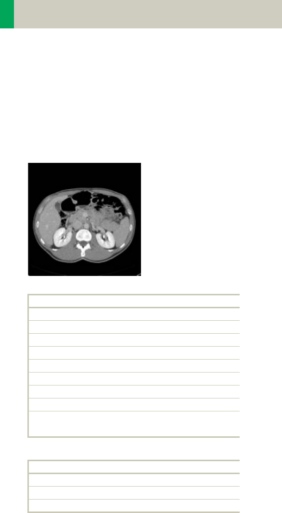
122
Abdomen
AbdomenSeq
Indications:
Sequential mode for all routine studies in the region of
abdomen, e.g., evaluation, follow-up examinations
etc.
The whole scan length covers 15.2 cm.
AbdSeq
kV 130
Effective mAs 70
Rotation time 1.0 sec
Slice collimation 4.0 mm
Slice width 8.0 mm
Feed/Scan 8.0 mm
Kernel B41s
CTDIVol 7.55 mGy
Effective dose Male: 2.35 mSv
Female: 2.75 mSv
Contrast medium IV injection
Start delay 50 – 60 sec.
Flow rate 3.0 ml/sec.
Total amount 100 ml
C2-025.630.01.01.02_APPLICATIONGUIDE_SPIRIT.book Page 122 Friday, April 8, 2005 9:55 AM

Abdomen
123
Hints
• You could repeat the same protocol by simply click-
ing the chronicle with the right mouse button for
“repeat“, e.g., when both non-contrast and contrast
studies are required.
• Water, rather than positive oral contrast agents
should be used. Give the last cup 200 ml just prior
positioning the patient. To ensure adequate filling of
the duodenal loop, lay the patient on the right side
for 5 minutes before performing the topogram.
• A pre-contrast examination is usually performed
only if no CT scans were previously acquired, to
exclude calculi in the common bile duct and to visu-
alize possible lesions in the liver.
C2-025.630.01.01.02_APPLICATIONGUIDE_SPIRIT.book Page 123 Friday, April 8, 2005 9:55 AM
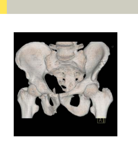
124
Pelvis
Overview
–Pelvis
Spiral mode for routine soft tissue pelvis studies
–Hip
Spiral mode for routine hip studies
–SI_Joints
Spiral mode for sacroiliac joints studies
C2-025.630.01.01.02_APPLICATIONGUIDE_SPIRIT.book Page 124 Friday, April 8, 2005 9:55 AM

Pelvis
125
Hints in General
• Topogram: TOP, 512 mm for pelvis studies and
256 mm for studies of the hip and SI Joints.
• Patient positioning:
Patient lying in supine position, arms positioned
comfortably above the head in the head-arm rest,
lower legs supported.
• A breathing command is not necessarily required for
the pelvic examination, since respiration does not
negatively influence this region.
• Rectal contrast medium administration:
Rectal contrast media is usually required to delineate
the rectum and sigmoid colon, if lower pelvic mass
or pathology are suspected. In some cases, air may
be substituted for a positive contrast agent. The use
of a vaginal tampon may be helpful in adult female
patients with suspected pelvis pathology.
• To further optimize MPR image quality we recom-
mend that you reduce one or more of the following:
collimation, reconstruction increment, and slice
width for image reconstruction.
• For pelvis studies, deselect CARE Dose for patients
> 120 kg.
Body Kernels
• As standard kernels for body tissue studies B31s or
B41s is recommended; softer images are obtained
with B20s.
C2-025.630.01.01.02_APPLICATIONGUIDE_SPIRIT.book Page 125 Friday, April 8, 2005 9:55 AM
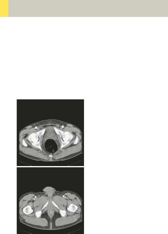
126
Pelvis
Pelvis
Indications:
Spiral mode for routine pelvis studies, e.g., processes
of the prostate, urinary bladder, rectum, gynecological
indications etc.
A typical range of 20 cm will be covered in 12 sec.
C2-025.630.01.01.02_APPLICATIONGUIDE_SPIRIT.book Page 126 Friday, April 8, 2005 9:55 AM

Pelvis
127
* If the examination performed requires a full urinary
bladder, wait at least 3 minutes following IV adminis-
tration of the contrast medium.
Pelvis
kV 130
Effective mAs 80
Rotation time 1.0 sec
Slice collimation 5.0 mm
Slice width 8.0 mm
Feed/Rotation 20.0 mm
Pitch Factor 2.0
Increment 8.0 mm
Kernel B41s
CTDIVol 8.62 mGy
Effective dose Male: 3.24 mSv
Female: 5.51 mSv
Contrast medium IV injection
Start delay 50 sec.*
Flow rate 2.0 – 3.0 ml/sec.
Total amount 100 – 120 ml
C2-025.630.01.01.02_APPLICATIONGUIDE_SPIRIT.book Page 127 Friday, April 8, 2005 9:55 AM
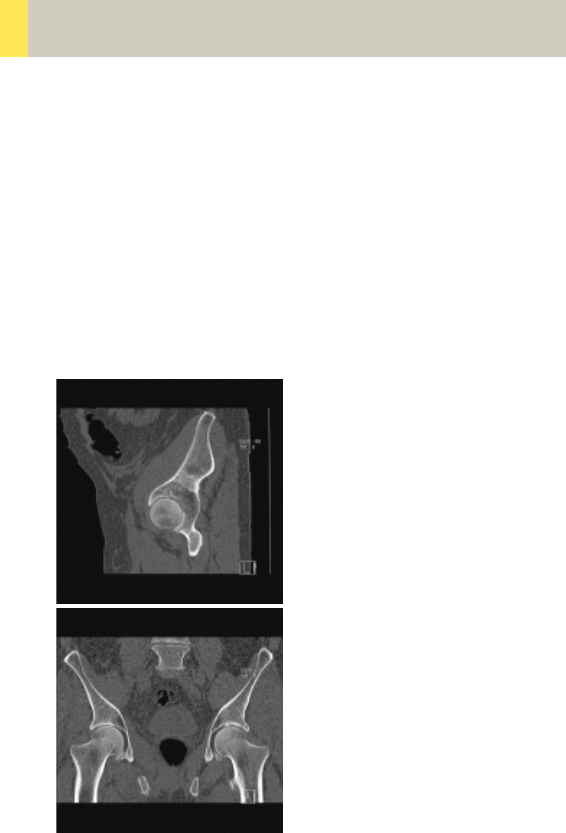
128
Pelvis
Hip
Indications:
Spiral mode for HiRes bone studies and soft tissue
studies of the Hip, e.g., evaluation of joint cavity,
masses, trauma, dysplasia, necrosis of the head of the
hip, congruence evaluations, orthopedic indications
etc.
A typical range of 10 cm will be covered in 35 sec.
C2-025.630.01.01.02_APPLICATIONGUIDE_SPIRIT.book Page 128 Friday, April 8, 2005 9:55 AM

Pelvis
129
Hints
• In case of 3D study only, images should be recon-
structed with at least 50% overlap in image recon-
struction and kernel B20s.
• If only one side is examined, it is advisable to enter
the side in the comment line on the Routine card.
Hip 2nd reconstr.
kV 130
Effective mAs 70
Rotation time 1.0 sec
Slice collimation 1.5 mm
Slice width 3.0 mm 2.0 mm
Feed/Rotation 3.0 mm
Pitch Factor 1.0
Increment 3.0 mm 1.5 mm
Kernel B70s B70s
CTDIVol 7.55 mGy
Effective dose Male:
1.78 mSv
Female:
1.66 mSv
C2-025.630.01.01.02_APPLICATIONGUIDE_SPIRIT.book Page 129 Friday, April 8, 2005 9:55 AM
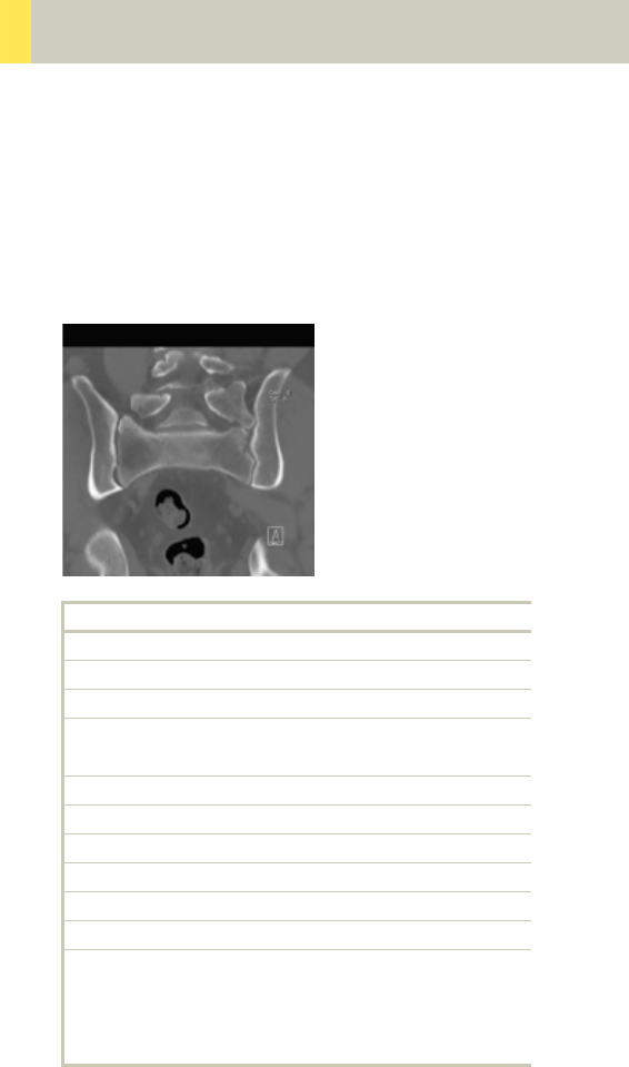
130
Pelvis
SI_Joints
Indications:
Spiral mode for bone studies of the sacroiliac joints.
A typical range of 8 cm will be covered in 18 sec.
SI_Joints 2nd reconstruction
kV 130
Effective mAs 80
Rotation time 1.0 sec
Slice
collimation
2.5 mm
Slice width 3.0 mm 3.0 mm
Feed/Rotation 5.0 mm
Pitch Factor 1.0
Increment 3.0 mm 2.0 mm
Kernel B70s B70s
CTDIVol 8.62 mGy
Effective dose Male:
1.44 mSv
Female:
1.93 mSv
C2-025.630.01.01.02_APPLICATIONGUIDE_SPIRIT.book Page 130 Friday, April 8, 2005 9:55 AM

Pelvis
131
C2-025.630.01.01.02_APPLICATIONGUIDE_SPIRIT.book Page 131 Friday, April 8, 2005 9:55 AM
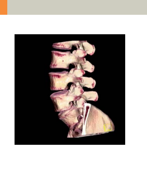
132
Spine
Overview
–C-Spine
Spiral mode for cervical spine studies
–C-SpineSeq
Sequential mode for cervical spine studies
–Spine
Spiral mode for routine lumbar and thoracic spine
studies
–SpineSeq
Sequential mode for lumbar and thoracic evaluation
of the discs
–Osteo
Sequential mode used for the application syngo
Osteo CT
C2-025.630.01.01.02_APPLICATIONGUIDE_SPIRIT.book Page 132 Friday, April 8, 2005 9:55 AM

Spine
133
Hints in General
• Topogram: Lateral, 512 mm for thoracic and lumbar
spine and 256 mm for the C-spine.
• Patient positioning for thoracic and lumbar spine
studies:
Patient lying in supine position, arms positioned
comfortably above the head in the head-arm rest,
lower legs supported.
• Patient positioning for cervical spine studies:
Patient lying in supine position, hyperextend neck
slightly, secure head well in head holder.
– Patient respiratory instruction: do not breathe, do
not swallow.
Any possible injuries to the spinal column should be
determined before beginning the examination and
taken into account when repositioning the patient.
Hints
• In case of 3D study only, images should be recon-
structed with at least 50% overlap in image recon-
struction and kernel B20s.
• In case of SSD study only, mAs value can be reduced
by 50%. Use kernel B20s and 50% overlap in image
reconstruction.
• For lumbar studies, place a cushion under the
patient’s knees. This will reduce the curve in the
spine and also make the patient more comfortable.
• For image reconstruction of bone studies, use kernel
B60.
C2-025.630.01.01.02_APPLICATIONGUIDE_SPIRIT.book Page 133 Friday, April 8, 2005 9:55 AM

134
Spine
• The CT scan following myelography must be per-
formed within 4 – 6 hours of the injection, other-
wise, the contrast density in the spinal canal will be
too high to obtain artifact-free images. Also, if possi-
ble, it is a good idea to roll the patient once, or scan
in a prone position. This will prevent the contrast
from pooling posterior to the spinal cord.
• If a prone scan is performed, breathing instructions
are recommended to avoid motion artifact in axial
source and MPR images.
• To further optimize MPR image quality, we recom-
mend that you reduce one or more of the following
parameters: collimation, reconstruction increment,
and slice width for image reconstruction.
C2-025.630.01.01.02_APPLICATIONGUIDE_SPIRIT.book Page 134 Friday, April 8, 2005 9:55 AM

Spine
135
Body Kernels
• As standard kernels for body tissue studies B31s or
B41s are recommended; softer images are obtained
with B20s.
• For higher sharpness, as is required e.g., in patient
protocols for cervical spine, shoulder, extremities,
thorax, lung, the kernels B50s, B60s, B70s are avail-
able.
C2-025.630.01.01.02_APPLICATIONGUIDE_SPIRIT.book Page 135 Friday, April 8, 2005 9:55 AM
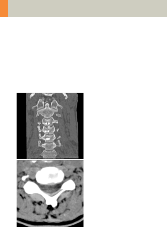
136
Spine
C-Spine
Indications:
Spiral mode for cervical spine studies, e.g., prolapse,
degenerative changes, trauma, tumors etc.
A range of 15 cm will be covered in 52 sec.
C2-025.630.01.01.02_APPLICATIONGUIDE_SPIRIT.book Page 136 Friday, April 8, 2005 9:55 AM

Spine
137
C-Spine 2nd reconstr.
kV 130
Effective mAs 90
Rotation time 1.0 sec
Slice collimation 1.5 mm
Slice width 3.0 mm 2.0 mm
Feed/Rotation 3.0 mm
Pitch Factor 1.0
Increment 3.0 mm 1.5 mm
Kernel B50s B50s
CTDIVol 9.70 mGy
Effective dose Male:
2.02 mSv
Female:
2.07 mSv
C2-025.630.01.01.02_APPLICATIONGUIDE_SPIRIT.book Page 137 Friday, April 8, 2005 9:55 AM

138
Spine
C-SpineSeq
Indications:
Sequential mode for cervical spine studies, e.g., pro-
lapse, degenerative changes, trauma, tumors, etc.
with a typical length for each range of 1.2 cm.
This protocol contains five ranges:
C2-C3, C3-C4, C4-C5, C5-C6, C6-C7
C2-3 C3-4 C4-5
kV 130 130 130
Effective mAs 170 170 170
Rotation time 1.5 sec 1.5 sec 1.5 sec
Slice
collimation
1.0 mm 1.0 mm 1.0 mm
Slice width 2.0 mm 2.0 mm 2.0 mm
Feed/Scan 2.0 mm 2.0 mm 2.0 mm
Kernel B50s B50s B50s
CTDIVol 18.33
mGy
18.33
mGy
18.33
mGy
Effective dose Male:
0.18 mSv
Female:
0.14 mSv
Male:
0.39 mSv
Female:
0.21 mSv
Male:
0.66 mSv
Female:
0.45 mSv
C2-025.630.01.01.02_APPLICATIONGUIDE_SPIRIT.book Page 138 Friday, April 8, 2005 9:55 AM

Spine
139
Hints
• Dental artifacts can be reduced by tilting the gantry.
• For MPRs and 3D post-processing, use spiral mode
with thinner slice and reconstruct images with 50%
overlap in image reconstruction. Define a long range
to cover the levels of interest in one block.
C5-6 C6-7
kV 130 130
Effective mAs 170 190
Rotation time 1.5 sec 1.5 sec
Slice collimation 1.0 mm 1.0 mm
Slice width 2.0 mm 2.0 mm
Feed/Scan 2.0 mm 2.0 mm
Kernel B50s B50s
CTDIVol 18.33 mGy 20.48 mGy
Effective dose Male:
0.66 mSv
Female:
0.73 mSv
Male:
0.30 mSv
Female:
0.50 mSv
C2-025.630.01.01.02_APPLICATIONGUIDE_SPIRIT.book Page 139 Friday, April 8, 2005 9:55 AM
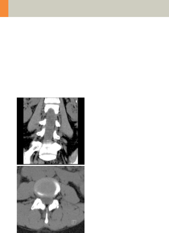
140
Spine
Spine
Indications:
Spiral mode for thoracic and lumbar spine studies,
e.g., prolapse, degenerative changes, trauma, tumors
etc.
A range of 15 cm will be covered in 48 sec.
C2-025.630.01.01.02_APPLICATIONGUIDE_SPIRIT.book Page 140 Friday, April 8, 2005 9:55 AM

Spine
141
Spine 2nd
reconstruction
kV 130
Effective mAs 120
Rotation time 1.5 sec
Slice
collimation
2.5 mm
Slice width 3.0 mm 3.0 mm
Feed/Rotation 5.0 mm
Pitch Factor 1.0
Increment 3.0 mm 2.0 mm
Kernel B31s B60s
CTDIVol 12.94 mGy
Effective dose Male:
2.94 mSv
Female:
6.75 mSv
C2-025.630.01.01.02_APPLICATIONGUIDE_SPIRIT.book Page 141 Friday, April 8, 2005 9:55 AM
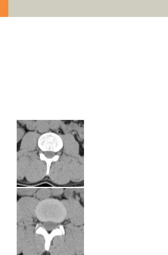
142
Spine
SpineSeq
Indications:
Sequence mode for spine studies, e.g., prolapse,
degenerative changes, trauma, tumors etc. with a typ-
ical length for each range of 1.5 cm.
This protocol contains three ranges:
L3-4, L4-L5, L5-S1
Three different typical gantry tilts are predefined:
for L3-L4: 0°, for L4-L5: +5° and for L5-S1: +15°
C2-025.630.01.01.02_APPLICATIONGUIDE_SPIRIT.book Page 142 Friday, April 8, 2005 9:55 AM

Spine
143
L3-4 L4-5 L5-S1
kV 130 130 130
Effective mAs 220 220 235
Rotation time 1.5 sec 1.5 sec 1.5 sec
Slice
collimation
1.5 mm 1.5 mm 1.5 mm
Slice width 3.0 mm 3.0 mm 3.0 mm
Feed/Scan 3.0 mm 3.0 mm 3.0 mm
Kernel B31s B31s B31s
CTDIVol 23.72
mGy
23.72
mGy
25.33
mGy
Effective dose Male:
0.58 mSv
Female:
0.92 mSv
Male:
0.63 mSv
Female:
1.21 mSv
Male:
0.64 mSv
Female:
2.35 mSv
C2-025.630.01.01.02_APPLICATIONGUIDE_SPIRIT.book Page 143 Friday, April 8, 2005 9:55 AM

144
Spine
Osteo
This is the scan protocol for the syngo Osteo CT appli-
cation package to assist the Physician with the quanti-
tative assessment of vertebral bone mineral density
(BMD) in the diagnosis and follow-up of osteopenia
and osteoporosis.
For obese patients, increase the mAs value to 120.
Load all ranges in the application “syngo Osteo CT”.
For further information, please refer to the chapter
“syngo Osteo CT“.
Osteo Osteo Osteo
kV 80 80 80
Effective mAs 81 81 81
Rotation time 1.0 sec 1.0 sec 1.0 sec
Slice
collimation
5.0 mm 5.0 mm 5.0 mm
Slice width 10.0 mm 10.0 mm 10.0 mm
Feed/Scan 0.0 mm 0.0 mm 0.0 mm
Kernel S80s S80s S80s
CTDIVol 2.23 mGy 2.23 mGy 2.23 mGy
Effective dose Male:
0.03 mSv
Female:
0.08 mSv
Male:
0.03 mSv
Female:
0.05 mSv
Male:
0.03 mSv
Female:
0.04 mSv
C2-025.630.01.01.02_APPLICATIONGUIDE_SPIRIT.book Page 144 Friday, April 8, 2005 9:55 AM

Spine
145
C2-025.630.01.01.02_APPLICATIONGUIDE_SPIRIT.book Page 145 Friday, April 8, 2005 9:55 AM
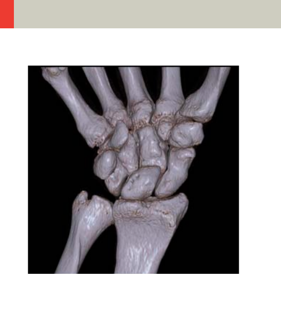
146
Upper Extremities
Overview
–WristHR
Spiral mode for routine high resolution wrist studies
–ExtrRoutineHR
Spiral mode for routine high resolution extremity
studies
C2-025.630.01.01.02_APPLICATIONGUIDE_SPIRIT.book Page 146 Friday, April 8, 2005 9:55 AM

Upper Extremities
147
Hints in General
• Topogram: TOP, 256 mm for joint studies.
• Patient positioning:
Depends on the region of examination.
In general, for bilateral studies, you should always
try to position the patient symmetrical whenever the
patient can comply.
For wrists and elbow scans:
Patient lying in prone position, hands stretched
above the head and lying flat on a Bocollo pillow,
ankles supported with a pad. Both wrists should be
examined together when necessary.
• Retrospective reconstruction can be done:
a)Use B31s kernel for soft tissue evaluation.
b)For targeted FoV images on the affected side, it is
advisable to enter the side being examined in the
comment line.
• In case of 3D study only, use kernel B20s and at least
50% overlap in image reconstruction.
• To further optimize MPR image quality, we recom-
mend that you reduce one or more of the following
parameters: collimation, reconstruction increment,
and slice width for image reconstruction.
C2-025.630.01.01.02_APPLICATIONGUIDE_SPIRIT.book Page 147 Friday, April 8, 2005 9:55 AM

148
Upper Extremities
Body Kernels
• As standard kernels for body tissue studies B31s or
B41s is recommended; softer images are obtained
with B20s.
• For higher sharpness, as is required e.g., in patient
protocols for cervical spine, shoulder, extremities,
thorax, lung, the kernels B50s, B60s, B70s are avail-
able.
C2-025.630.01.01.02_APPLICATIONGUIDE_SPIRIT.book Page 148 Friday, April 8, 2005 9:55 AM

Upper Extremities
149
C2-025.630.01.01.02_APPLICATIONGUIDE_SPIRIT.book Page 149 Friday, April 8, 2005 9:55 AM
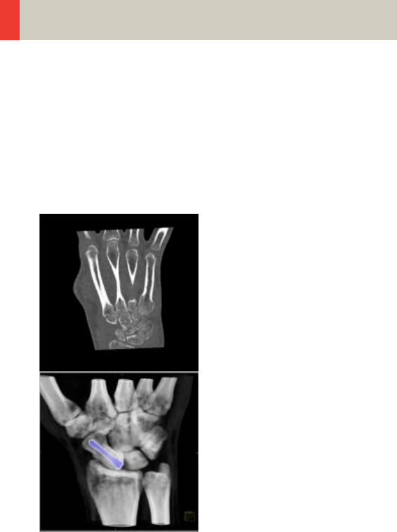
150
Upper Extremities
WristHR
Indications:
Spiral mode for HiRes bone study of the wrist, e.g.,
trauma, orthopedic indications etc.
A range of 6 cm will be covered in 32 sec.
C2-025.630.01.01.02_APPLICATIONGUIDE_SPIRIT.book Page 150 Friday, April 8, 2005 9:55 AM

Upper Extremities
151
Hint
• For image reconstruction of soft tissue, use kernel
B31s.
WristHR 2nd reconstruction
kV 130
Effective mAs 30
Rotation time 1.0 sec
Slice collimation 1.0 mm
Slice width 2.0 mm 1.25 mm
Feed/Rotation 2.0 mm
Pitch Factor 1.0
Increment 2.0 mm 0.8 mm
Kernel U90s U90s
CTDIVol 3.23 mGy
Effective dose Male:
< 0.01 mSv
Female:
< 0.01 mSv
C2-025.630.01.01.02_APPLICATIONGUIDE_SPIRIT.book Page 151 Friday, April 8, 2005 9:55 AM

152
Upper Extremities
ExtrRoutineHR
Indications:
Spiral mode for HiRes bone study, e.g., trauma, ortho-
pedic indications etc.
A range of 10 cm will be covered in 52 sec.
Hint
• For image reconstruction of soft tissue, use kernel
B31s.
ExtrHR 2nd reconstruction
kV 130
Effective mAs 30
Rotation time 1.0 sec
Slice
collimation
1.0 mm
Slice width 2.0 mm 1.25 mm
Feed/Rotation 2.0 mm
Pitch Factor 1.0
Increment 2.0 mm 0.8 mm
Kernel U90s U90s
CTDIVol 3.23 mGy
Effective dose Male:
< 0.01 mSv
Female:
< 0.01 mSv
C2-025.630.01.01.02_APPLICATIONGUIDE_SPIRIT.book Page 152 Friday, April 8, 2005 9:55 AM

Upper Extremities
153
C2-025.630.01.01.02_APPLICATIONGUIDE_SPIRIT.book Page 153 Friday, April 8, 2005 9:55 AM
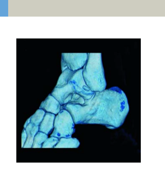
154
Lower Extremities
Overview
–KneeHR
Spiral mode for high resolution routine knee studies
–FootHR
Spiral mode for high resolution routine foot studies
–ExtrRoutineHR
Spiral mode for high resolution routine extremity
studies
C2-025.630.01.01.02_APPLICATIONGUIDE_SPIRIT.book Page 154 Friday, April 8, 2005 9:55 AM

Lower Extremities
155
Hints in General
• Topogram: TOP, 256 mm for joint studies.
• Patient positioning:
Depends on the region of examination. In general,
for bilateral studies, you should always try to posi-
tion the patient symmetrical whenever the patient
can comply.
• For knee scan:
Patient lying in supine position, feet first, promote
relaxation by placing Bocollo pillows between knees
and feet, bind feet together. The only exceptions are
extremely light patients. The latter can remove the
leg not being examined from the gantry by bending
it 90° at the hip and the knee and placing the bottom
of the same foot against the gantry casing.
• For ankle and feet scans:
Patient lying in supine position, feet first. Bind both
ankles together if necessary to assure the TOP posi-
tion of both feet.
• Retrospective reconstruction can be done:
a)Use B31s kernel for soft tissue evaluation.
b)For targeted FoV images on the affected side, it is
advisable to enter the side being examined in the
comment line.
• To further optimize MPR image quality, we recom-
mend that you reduce one or more of the following
parameters: collimation, reconstruction increment,
and slice width for image reconstruction.
C2-025.630.01.01.02_APPLICATIONGUIDE_SPIRIT.book Page 155 Friday, April 8, 2005 9:55 AM

156
Lower Extremities
Body Kernels
• As standard kernels for body tissue studies B31s or
B41s is recommended; softer images are obtained
with B20s.
• For higher sharpness, as is required e.g., in patient
protocols for cervical spine, shoulder, extremities,
thorax, lung, the kernels B50s, B60s, B70s are avail-
able.
• In case of 3D study only, the mAs value can be
reduced by 50%. Use kernel B20s and at least 50%
overlap in image reconstruction.
C2-025.630.01.01.02_APPLICATIONGUIDE_SPIRIT.book Page 156 Friday, April 8, 2005 9:55 AM

Lower Extremities
157
C2-025.630.01.01.02_APPLICATIONGUIDE_SPIRIT.book Page 157 Friday, April 8, 2005 9:55 AM
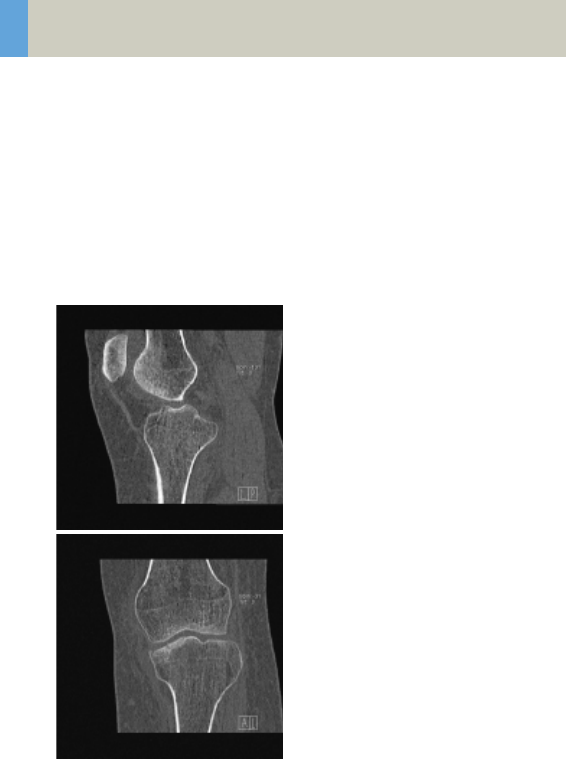
158
Lower Extremities
KneeHR
Indications:
Spiral mode for high resolution studies of the knee,
e.g., masses, trauma, disorders of the joint etc.
A range of 10 cm will be covered in 52 sec.
C2-025.630.01.01.02_APPLICATIONGUIDE_SPIRIT.book Page 158 Friday, April 8, 2005 9:55 AM

Lower Extremities
159
Hint
• For image reconstruction of soft tissue, use kernel
B31s.
KneeHR 2nd reconstruction
kV 130
Effective mAs 35
Rotation time 1.0 sec
Slice
collimation
1.0 mm
Slice width 3.0 mm 1.25 mm
Feed/Rotation 2.0 mm
Pitch Factor 1.0
Increment 3.0 mm 0.8 mm
Kernel U90s U90s
CTDIVol 3.77 mGy
Effective dose Male:
0.01 mSv
Female:
0.01 mSv
C2-025.630.01.01.02_APPLICATIONGUIDE_SPIRIT.book Page 159 Friday, April 8, 2005 9:55 AM
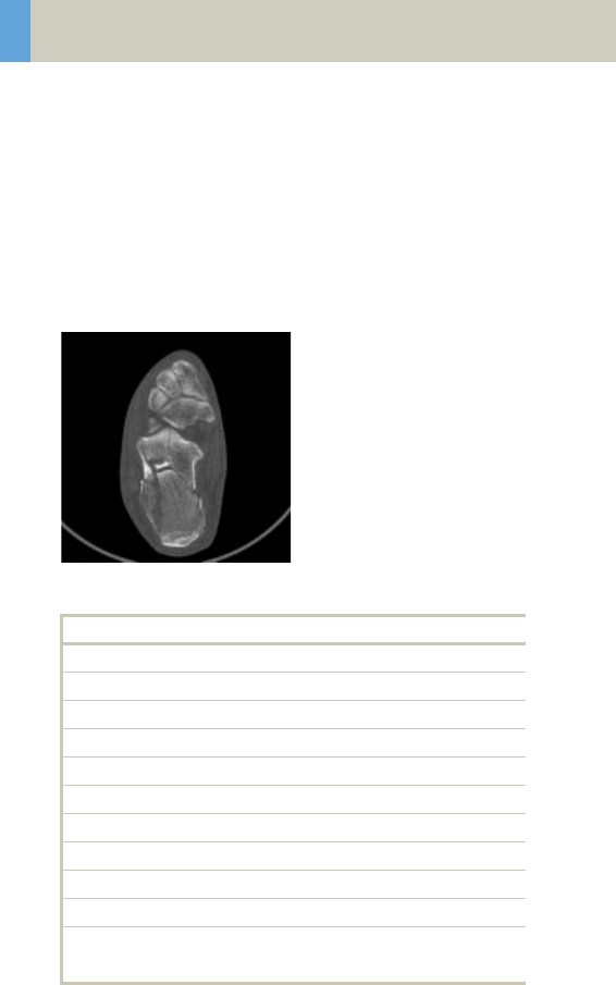
160
Lower Extremities
FootHR
Indications:
Spiral mode for high resolution studies of the foot,
e.g., masses, trauma, disorders of the joint etc.
A range of 10 cm will be covered in 52 sec.
Hint
• For image reconstruction of soft tissue, use kernel
B31s.
FootHR 2nd reconstruction
kV 130
Effective mAs 30
Rotation time 1.0 sec
Slice collimation 1.0 mm
Slice width 3.0 mm 1.25 mm
Feed/Rotation 2.0 mm
Pitch Factor 1.0
Increment 3.0 mm 0.8 mm
Kernel U90s U90s
CTDIVol 3.23 mGy
Effective dose Male: 0.01 mSv
Female: 0.01 mSv
C2-025.630.01.01.02_APPLICATIONGUIDE_SPIRIT.book Page 160 Friday, April 8, 2005 9:55 AM

Lower Extremities
161
ExtrRoutineHR
Indications:
Spiral mode for HiRes bone study, e.g., trauma, ortho-
pedic indications etc.
A range of 10 cm will be covered in 52 sec.
Hint
• For image reconstruction of soft tissue, use kernel
B31s.
ExtrHR 2nd reconstruction
kV 130
Effective mAs 30
Rotation time 1.0 sec
Slice collimation 1.0 mm
Slice width 2.0 mm 1.25 mm
Feed/Rotation 2.0 mm
Pitch Factor 1.0
Increment 2.0 mm 0.8 mm
Kernel U90s U90s
CTDIVol 3.23 mGy
Effective dose Male: 0.01 mSv
Female: 0.01 mSv
C2-025.630.01.01.02_APPLICATIONGUIDE_SPIRIT.book Page 161 Friday, April 8, 2005 9:55 AM
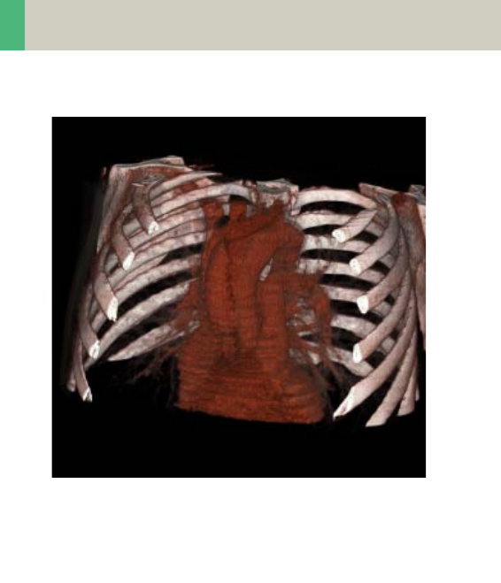
162
Vascular
Overview
–HeadAngio/HeadAngio08s
Spiral mode for head CTAngio studies
–CarotidAngio/CarotidAngio08s
Spiral mode for carotid CTAngio studies
–ThorAngio/ThorAngio08s
Spiral mode for chest CTAngio studies
–Embolism
Spiral mode for pulmonary embolism studies
–BodyAngioRoutine/BodyAngioRoutine08s
Spiral mode for body CTAngio studies
–BodyAngioFast
Spiral mode for fast body CTAngio studies
C2-025.630.01.01.02_APPLICATIONGUIDE_SPIRIT.book Page 162 Friday, April 8, 2005 9:55 AM

Vascular
163
Hints in General
• Topogram: TOP, 512/1024 or LAT 256
• Patient positioning:
Patient lying in supine position, arms positioned
comfortably above the head in the head-arm rest,
lower legs supported.
• Patient respiratory instructions: inspiration.
• Oral administration of contrast medium:
The use of water will not obscure the blood vessels,
thus allowing CTA post-processing to be performed
easily afterwards.
• Be careful when examining pheochromocytoma
patients. Administration of an IV CM injection in
such cases may trigger a hypertensive crisis!
• To further optimize MPR image quality, we recom-
mend that you reduce one or more of the following
parameters: collimation, reconstruction increment
and slice width for image reconstruction.
Head Kernels
• For soft tissue head studies, the standard kernel is
H41s; softer images are obtained with H31s or H21s,
sharper images with H50s.
Body Kernels
• As standard kernels for body tissue studies B31s or
B41s is recommended; softer images are obtained
with B20s.
C2-025.630.01.01.02_APPLICATIONGUIDE_SPIRIT.book Page 163 Friday, April 8, 2005 9:55 AM
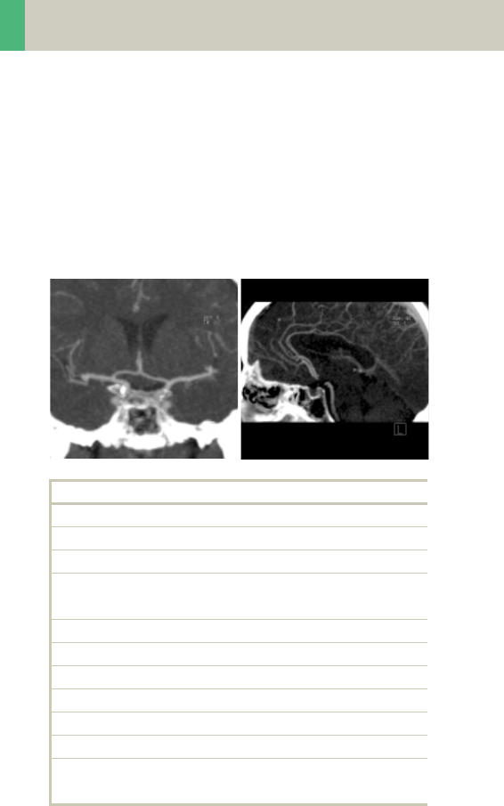
164
Vascular
HeadAngio/HeadAngio08s
Indications:
Spiral mode for cerebral CT Angios, e.g., cerebral vas-
cular abnormalities, tumors and follow-up studies etc.
A range of 6 cm will be covered in 32/26 sec.
HeadAngio 2nd reconstruction
kV 130
Effective mAs 50
Rotation time 0.8/1.0 sec
Slice
collimation
1.0 mm
Slice width 3.0 mm 1.25 mm
Feed/Rotation 2.0 mm
Pitch Factor 1.0
Increment 3.0 mm 0.8 mm
Kernel H31s H31s
CTDIVol 11.39 mGy
Effective dose Male: 0.26 mSv
Female: 0.30 mSv
C2-025.630.01.01.02_APPLICATIONGUIDE_SPIRIT.book Page 164 Friday, April 8, 2005 9:55 AM

Vascular
165
Hints
• Use of CARE Bolus with monitoring scans positioned
at the level of the basilar artery or carotid artery. Set
the trigger threshold at 120 HU, or use manual trig-
gering.
• An automatic bone correction and an advanced algo-
rithm allow for improved head image quality, with-
out any additional post-processing.
Contrast medium IV injection
Start delay 18 sec.
Flow rate 3.5 ml/sec.
Total amount 75 ml
C2-025.630.01.01.02_APPLICATIONGUIDE_SPIRIT.book Page 165 Friday, April 8, 2005 9:55 AM
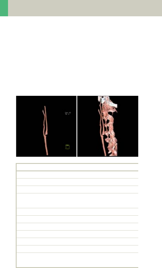
166
Vascular
CarotidAngio/CarotidAngio08s
Indications:
Noninvasive CT angiography of carotid stenosis or
occlusions, plaques course abnormalities of the
carotids and vertebral arteries, etc.
A range of 12 cm will be covered in 32/26 sec.
CarotidAngio 2nd reconstruction
kV 130
Effective mAs 55
Rotation time 0.8/1.0 sec
Slice
collimation
1.0 mm
Slice width 5.0 mm 1.25 mm
Feed/Rotation 4.0 mm
Pitch Factor 2.0
Increment 5.0 mm 0.8 mm
Kernel B31s B31s
CTDIVol 5.93 mGy
Effective dose Male: 1.15 mSv
Female: 1.25 mSv
C2-025.630.01.01.02_APPLICATIONGUIDE_SPIRIT.book Page 166 Friday, April 8, 2005 9:55 AM

Vascular
167
Hints
• CARE Bolus may be used to optimize the bolus tim-
ing.
• Set the ROI for monitoring scan in the aortic arch
with triggering threshold of 120 HU, or use manual
triggering.
• High quality 2D & 3D post-processing can be
achieved using a thin slice thickness and 50% over-
lap in image reconstruction.
• MPR Thick and MIP Thin images can be created very
quickly on the 3D card by just clicking on the appro-
priate icons. The thickness of these reconstructed
images can be defined by clicking on the icons with
the right mouse to open the entry field.
Contrast medium IV injection
Start delay 15 sec.
Flow rate 4 ml/sec.
Total amount 90 ml
C2-025.630.01.01.02_APPLICATIONGUIDE_SPIRIT.book Page 167 Friday, April 8, 2005 9:55 AM
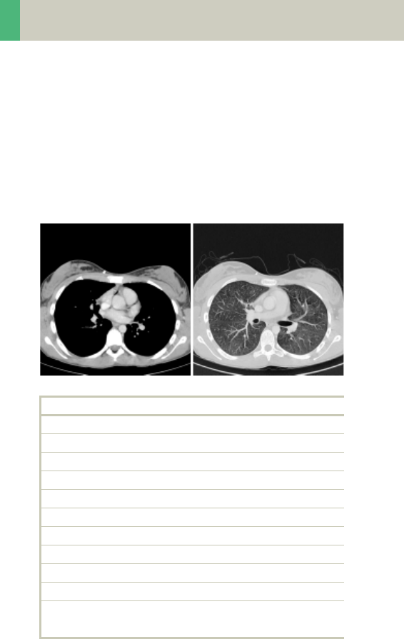
168
Vascular
ThorAngio/ThorAngio08s
Indications:
Spiral study for location and extent of aneurysms, dis-
section, and ruptures of the thoriac aorta.
A range of 20 cm will be covered in 24/19 sec.
ThorAngio 2nd reconstruction
kV 130
Effective mAs 55
Rotation time 0.8/1.0 sec
Slice collimation 2.5 mm
Slice width 5.0 mm 3.0 mm
Feed/Rotation 9.0 mm
Pitch Factor 1.8
Increment 5.0 mm 2.0 mm
Kernel B31s B31s
CTDIVol 5.93 mGy
Effective dose Male: 1.91 mSv
Female: 2.67 mSv
C2-025.630.01.01.02_APPLICATIONGUIDE_SPIRIT.book Page 168 Friday, April 8, 2005 9:55 AM

Vascular
169
Hints
• CARE Bolus may be used to optimize the bolus tim-
ing.
• Set the ROI for monitoring scan in the aortic arch
with triggering threshold of 120 HU, or use manual
triggering.
• High quality 2D & 3D post-processing can be
achieved using a thin slice thickness and 50% over-
lap in image reconstruction.
• Thick MPRs and ThinMIPs can be created very quickly
on the 3D card by just clicking on the appropriate
icons. The thickness of these reconstructed images
can be defined by clicking on the icons with the right
mouse to open the entry field.
• To display an SSD of the thoracic aorta without bone
included, editing is necessary.
Contrast medium IV injection
Start delay 10 – 25 sec.
Flow rate 2.5 ml/sec.
Total amount 80 ml
C2-025.630.01.01.02_APPLICATIONGUIDE_SPIRIT.book Page 169 Friday, April 8, 2005 9:55 AM
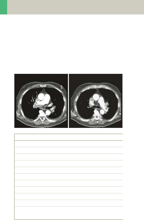
170
Vascular
Embolism
Indications:
Spiral mode for Pulmonary Emboli studies.
A range of 15 cm will be covered in 24 sec.
Embolism 2nd reconstruction
kV 130
Effective mAs 55
Rotation time 0.8 sec
Slice collimation 1.5 mm
Slice width 3.0 mm 2.0 mm
Feed/Rotation 5.4 mm
Pitch Factor 1.8
Increment 3.0 mm 1.5 mm
Kernel B31s B31s
CTDIVol 5.93 mGy
Effective dose Male: 1.56 mSv
Female: 2.07 mSv
C2-025.630.01.01.02_APPLICATIONGUIDE_SPIRIT.book Page 170 Friday, April 8, 2005 9:55 AM

Vascular
171
Hints
• CARE Bolus may be used to optimize the bolus tim-
ing.
• Set the ROI for monitoring scan in the pulmonary
trunk with triggering threshold of 120 HU, or use
manual triggering.
• You could repeat the same protocol by simply click-
ing the chronicle with the right mouse button for
"repeat".
Contrast medium IV injection
Start delay 6 – 10 sec.
Flow rate 4 ml/sec.
Total amount 80 – 100 ml
C2-025.630.01.01.02_APPLICATIONGUIDE_SPIRIT.book Page 171 Friday, April 8, 2005 9:55 AM
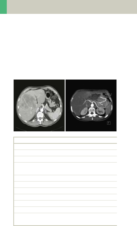
172
Vascular
BodyAngioRoutine/
BodyAngioRoutine08s
Indications:
Spiral mode for abdominal CTA studies.
A range of 20 cm will be covered in 39/31 sec.
.
BodyAngio 2nd reconstruction
kV 130
Effective mAs 55
Rotation time 0.8/1.0 sec
Slice
collimation
1.5 mm
Slice width 5.0 mm 3.0 mm
Feed/Rotation 5.4 mm
Pitch Factor 1.8
Increment 5.0 mm 2.0 mm
Kernel B31s B31s
CTDIVol 5.93 mGy
Effective dose Male: 2.17 mSv
Female: 2.68 mSv
C2-025.630.01.01.02_APPLICATIONGUIDE_SPIRIT.book Page 172 Friday, April 8, 2005 9:55 AM

Vascular
173
Hints
• CARE Bolus may be used to optimize the bolus tim-
ing.
• Set the ROI for monitoring scan in the abdominal
aorta with triggering threshold of 120 HU, or use
manual triggering.
• Do not administer oral contrast medium, as this
impairs the editing of MIP/SSD/VRT images.
• Use water as oral contrast.
• The length of the CM spiral in the topogram (via the
table position) can be planned exactly by means of
pre-contrast images.
• Pre-contrast images are used to visualize calcifica-
tion.
• Excellent post-processed images can be created
using a thin slice thickness and overlapping images,
i.e. the increment should be smaller than the slice
thickness.
Contrast medium IV injection
Start delay 20 – 25 sec.
Flow rate 3.0 – 3.5 ml/sec.
Total amount 100 – 120 ml
C2-025.630.01.01.02_APPLICATIONGUIDE_SPIRIT.book Page 173 Friday, April 8, 2005 9:55 AM
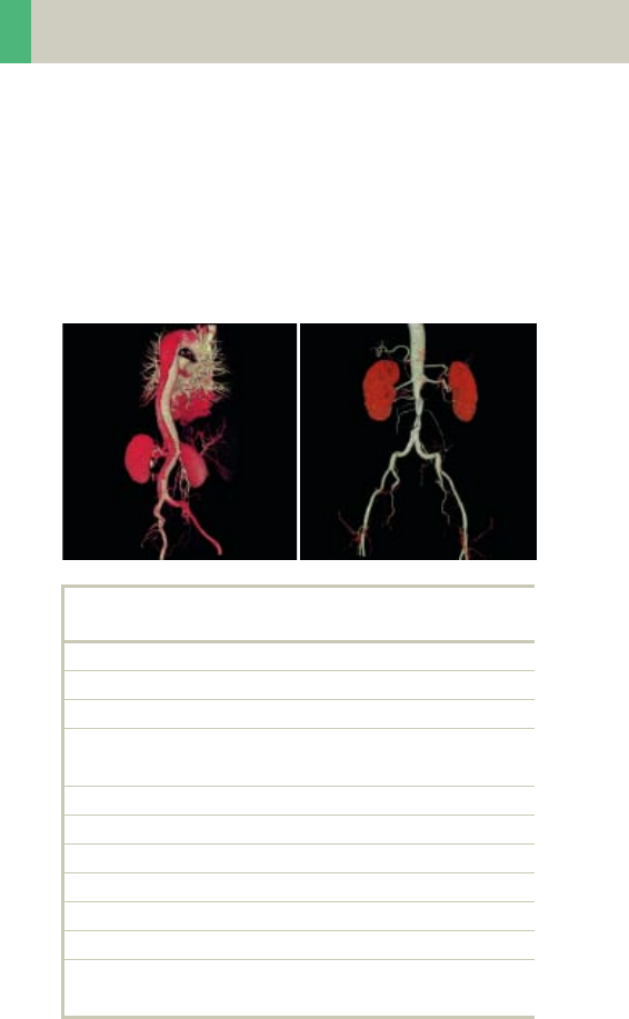
174
Vascular
BodyAngioFast
Indications:
Spiral mode for longer coverage and larger vessels.
A range of 20 cm will be covered in 18 sec.
BodyAngio 2nd
reconstruction
kV 130
Effective mAs 55
Rotation time 0.8 sec
Slice
collimation
2.5 mm
Slice width 5.0 mm 3.0 mm
Feed/Rotation 10.0 mm
Pitch Factor 2.0
Increment 5.0 mm 2.0 mm
Kernel B31s B31s
CTDIVol 5.93 mGy
Effective dose Male: 2.23 mSv
Female: 2.77 mSv
C2-025.630.01.01.02_APPLICATIONGUIDE_SPIRIT.book Page 174 Friday, April 8, 2005 9:55 AM

Vascular
175
Hints
• CARE Bolus may be used to optimize the bolus tim-
ing.
• Set the ROI for monitoring scan in the abdominal
aorta with triggering threshold of 120 HU, or use
manual triggering.
• Do not administer oral contrast medium, as this
impairs the editing of MIP/SSD/VRT images.
• Use water as oral contrast.
• The length of the CM spiral in the topogram (via the
table position) can be planned exactly by means of
pre-contrast images.
• Precontrast images are used to visualize calcifica-
tion.
• Excellent post-processed images can be created
using a thin slice thickness and overlapping images,
i.e. the increment should be smaller than the slice
thickness.
Contrast medium IV injection
Start delay 20 sec.
Flow rate 3.5 ml/sec.
Total amount 120 ml
C2-025.630.01.01.02_APPLICATIONGUIDE_SPIRIT.book Page 175 Friday, April 8, 2005 9:55 AM

176
Specials
Overview
The examination protocols designed for some of these
applications are under the “Special” folder.
Trauma
In any trauma situation, time means life and the qual-
ity of life for the survivor. In order to facilitate the
examinations, two protocols are provided.
–PolyTrauma: This is a combined mode for the exam-
ination of multiple ranges, e.g. Head, Neck, Thorax,
Abdomen and Pelvis
–HeadTrauma: Spiral head protocol with a FoV of 500
and therefore lowered image quality
Interventional CT
–Biopsy: The biopsy protocol is sequential mode with-
out table feed, using a 10 mm slice thickness.
Test Bolus
–TestBolus: This mode can be used to test the start
delay of an optimal enhancement after the contrast
medium injection.
C2-025.630.01.01.02_APPLICATIONGUIDE_SPIRIT.book Page 176 Friday, April 8, 2005 9:55 AM

Specials
177
Trauma
In any trauma situation, time means life and the qual-
ity of life for the survivor.
This is a combined mode for the examination of multi-
ple ranges, e.g., Head, Neck, Thorax, Abdomen and
Pelvis.
The Basics
• Check that the emergency drug trolley is well
stocked and that all accessories such as in-room oxy-
gen supply, respirator and resuscitation equipment
that may be required during the examination are in
working order.
• Prepare the CT room before admitting the patient,
e.g., load IV contrast into the injector.
• Know, observe and practice the standard hospital
operating policy for handling a patient in distress
e.g., Code Blue for cardiac and respiratory arrest.
• Any possible injuries to the spinal column should be
determined before beginning the examination and
taken into account when shifting and positioning
the patient.
• Ensure that all vital lines e.g., IV tubing and oxygen
tubing are not trapped under the patient or between
the table and the cradle. Make allowance for the
length of tubing required for the topogram scan
range.
• Never leave patients unattended at any time during
the procedure.
• Observe the vital signs e.g., ECG, respiration, etc. at
all times during the procedure.
• Finish the examination in the shortest possible time.
C2-025.630.01.01.02_APPLICATIONGUIDE_SPIRIT.book Page 177 Friday, April 8, 2005 9:55 AM

178
Specials
PolyTrauma
Two times 2 combined recon jobs are predefined, head
with neck and thorax with abdomen.
A range for the Head of 11 cm will be covered in
20 sec., a range for the Neck of 14 cm will be covered
in 30 sec.
Take a new Topogram for the thorax and abdomen
ranges.
Head Neck
kV 130 130
Effective mAs 110 90
Rotation time 1.5 sec 1.0 sec
Slice collimation 5.0 mm 2.5 mm
Slice width 6.0 mm 3.0 mm
Feed/Rotation 10.0 mm 5.0 mm
Pitch Factor 1.0 1.0
Increment 6.0 mm 3.0 mm
Kernel H31s B50s
CTDIVol 25.05 mGy 9.70 mGy
Effective dose Male:
1.02 mSv
Female:
1.08 mSv
Male:
1.69 mSv
Female:
1.81 mSv
C2-025.630.01.01.02_APPLICATIONGUIDE_SPIRIT.book Page 178 Friday, April 8, 2005 9:55 AM

Specials
179
A range for the Thorax of 25 cm will be covered in
15 sec., a range for the AbdPelvis of 20 cm will be cov-
ered in 12 sec.
• For long range scanning, please pay attention to the
mark of scannable range on the table mattress while
positioning the patient.
• In some cases, it might be advisable to position the
patient feet first so that there will be more space for
the intensive care equipment around.
Thorax AbdPelvis
kV 130 130
Effective mAs 40 60
Rotation time 1.0 sec 1.0 sec
Slice collimation 5.0 mm 5.0 mm
Slice width 8.0 mm 8.0 mm
Feed/Rotation 20.0 mm 20.0 mm
Pitch Factor 2.0 2.0
Increment 8.0 mm 8.0 mm
Kernel B41s B41s
CTDIVol 4.31 mGy 6.47 mGy
Effective dose Male:
1.82 mSv
Female:
2.45 mSv
Male:
2.59 mSv
Female:
3.31 mSv
C2-025.630.01.01.02_APPLICATIONGUIDE_SPIRIT.book Page 179 Friday, April 8, 2005 9:55 AM

180
Specials
HeadTrauma
A spiral mode for emergency head studies with a max.
FoV of 500 mm. A typical scan range of 40/80 cm will
be covered in 23/27 sec.
Base Cerebrum
kV 130 130
Effective mAs 110 110
Rotation time 1.5 sec 1.0 sec
Slice collimation 1.5 mm 2.5 mm
Slice width 3.0 mm 8.0 mm
Feed/Rotation 3.0 mm 5.0 mm
Pitch Factor 1.0 1.0
Increment 3.0 mm 8.0 mm
Kernel H31s H31s
CTDIVol 25.05 mGy 25.05 mGy
Effective dose Male:
0.37 mSv
Female:
0.51 mSv
Male:
0.70 mSv
Female:
0.86 mSv
C2-025.630.01.01.02_APPLICATIONGUIDE_SPIRIT.book Page 180 Friday, April 8, 2005 9:55 AM

Specials
181
Interventional CT
To facilitate CT interventional procedures, the follow-
ing protocols are provided. Any of these protocols can
be appended to a spiral protocol for CT interventional
procedures, such as biopsy, abscess drainage, pain
therapy, minimum invasive operations, joint studies,
and arthrograms. Adjust the mAs according to the
body region before loading.
10 scans are predefined. You can repeat it by clicking
the chronicle with the right mouse button and select
“repeat”, or by simply changing the number of scans to
99 before you start the first scan.
You can “Append” any routine protocol after the inter-
ventional procedure for a final check and documenta-
tion, e.g., a short range of spiral scanning for the
biopsy region.
The table height can be adjusted to minimum
255 mm.
C2-025.630.01.01.02_APPLICATIONGUIDE_SPIRIT.book Page 181 Friday, April 8, 2005 9:55 AM

182
Specials
Biopsy
Indications:
This is the conventional sequential mode without table
feed using a 10 mm slice.
Hint
This protocol can be appended to a spiral protocol for
CT interventional procedures, such as biopsy, abscess
drainage, pain therapy, minimum invasive operations,
joint studies, and arthrograms.
Biopsy
kV 130
Effective mAs 80
Rotation time 1.0 sec
Slice collimation 5.0 mm
Slice width 10.0 mm
Feed/Scan 0.0 mm
Kernel B31s
CTDIVol 8.62 mGy
C2-025.630.01.01.02_APPLICATIONGUIDE_SPIRIT.book Page 182 Friday, April 8, 2005 9:55 AM

Specials
183
TestBolus
Indications:
This mode can be used to test the start delay of an opti-
mal enhancement after the contrast medium injec-
tion.
TestBolus
kV 80
Effective mAs 110
Rotation time 1.0 sec
Slice collimation 5.0 mm
Slice width 10.0 mm
Feed/Scan 0.0 mm
Kernel B31s
CTDIVol 3.03 mGy
C2-025.630.01.01.02_APPLICATIONGUIDE_SPIRIT.book Page 183 Friday, April 8, 2005 9:55 AM

184
Children
Overview
The scan protocols for children are defined according
to body regions – Head, Neck, Shoulder, Thorax, Abdo-
men, Pelvis, Spine, Upper Extremities, Lower Extremi-
ties, Vascular, Specials and Private.
For children six (6) years and older, use the adult pro-
tocols.
Whenever possible, 80 kV is used instead of 130 kV,
either to exploit the significantly higher image con-
trast of iodine contrast media at 80 kV or to reach a
lower dose level than possible with 130 kV.
C2-025.630.01.01.02_APPLICATIONGUIDE_SPIRIT.book Page 184 Friday, April 8, 2005 9:55 AM

Children
185
•Head
–HeadRoutine_Baby
Spiral mode for routine baby head studies
–HeadRoutine_Child
Spiral mode for routine children head studies
–HeadSeq_Baby
Sequential mode for routine baby head studies
–HeadSeq_Child
Sequential mode for routine children head studies
–InnerEar
Spiral mode for inner ear studies
–SinusOrbi
Spiral mode for routine sinus or orbital studies
•Neck
– Neck
Spiral mode for soft tissue routine neck studies
•Thorax
–ThoraxRoutine_Baby
Spiral mode for routine baby chest studies
–ThoraxRoutine_Child
Spiral mode for routine children chest studies
–ThoraxHRSeq_Baby
Sequential mode for high resolution baby lung
studies
–ThoraxHRSeq_Child
Sequential mode for high resolution children lung
studies
•Abdomen
–Abdomen_Baby
Spiral mode for routine baby abdominal studies
–Abdomen_Child
Spiral mode for routine children abdominal stud-
ies
C2-025.630.01.01.02_APPLICATIONGUIDE_SPIRIT.book Page 185 Friday, April 8, 2005 9:55 AM

186
Children
•Spine
–Spine_Baby
Spiral mode for routine baby spine studies
–Spine_Child
Spiral mode for routine children spine studies
•Extremities
–ExtrHR_Baby
Spiral mode for routine baby high resolution
extremity studies
–ExtrHR_Child
Spiral mode for routine children high resolution
extremity studies
•Vascular
– HeadAngio/HeadAngio08s
Spiral mode for head CTAngio studies
–CarotidAngio/CarotidAngio08s
Spiral mode for carotid CTAngio studies
–BodyAngio/BodyAngio08s
Spiral mode for body CTAngio studies
•Specials
–NeonateBody
Spiral mode for neonate studies
C2-025.630.01.01.02_APPLICATIONGUIDE_SPIRIT.book Page 186 Friday, April 8, 2005 9:55 AM

Children
187
Hints in General
1.Topograms: 256 mm lateral topograms are defined
for the head modes, and 512 mm TOP topograms
are defined for the body modes. Please keep in mind
that the children’s size can be dramatically different.
You should press the “Hold Measurement“ button
whenever the range shown on the real-time grow-
ing topogram is long enough, in order to avoid
unnecessary radiation.
2. Gantry tilt is available for both, sequence and spiral
scanning. However, image artifacts may occur if spi-
rals are acquired with a tilt angle greater than 8°.
3.For all head studies, it is very important for image
quality purposes to position the patient in the center
of the scan field. Use the lateral laser beam to make
sure that the patient is positioned in the center.
4.Warm surroundings and dimmed lighting are helpful
to make children more cooperative.
5.Sedation: Although the advent of the Multislice CT
scanner has enabled the user to scan through an
area of interest much faster than ever, sometimes,
patient motion can still lead to severe motion arti-
facts seen on the resultant images. This becomes a
factor especially with infants and younger children
who are unable to hold still for the exam. Sedating
this population may be a viable option for your insti-
tution. Of course, appropriate protocols need to be
established at your specific institution. For instance,
the drug of choice for specific ages/weights of these
patients (taking into consideration the total time of
the exam), the form of administration, patient
preps, adequate monitoring of the patient (pre-scan,
during the exam and post-scan) etc. should all be
taken into consideration.
C2-025.630.01.01.02_APPLICATIONGUIDE_SPIRIT.book Page 187 Friday, April 8, 2005 9:55 AM

188
Children
The proper personnel and equipment must also be
readily available in the event of a problem.
6.Oral and rectal contrast administration: Depending
on the reason for the exam/status of the patient, oral
contrast may or may not be given to these patients.
In general, oral contrast is recommended to opacify
the intestinal tract, as unopacified bowel can have
the appearance of abdominal fluid or mass effect.
Oral, as well as rectal contrast may be required. Usu-
ally, a diluted mixture of iodine and water is used as
an oral agent. Different substances can be added to
this mixture to help reduce the bitter taste and make
it more pleasing to the child (apple juice and fruit
drink mixes are just a few of these). Barium may of
course be used in some cases as well. Negative con-
trast agents such as water are becoming more pop-
ular for delineation of stomach or bowel wall bor-
ders, or when 3D reconstructions are needed. The
user needs to be aware of all the contraindications of
any of the contrast agents they are using. Please
refer to the specific vendor’s recommendations.
7.I.V. contrast administration: In general, 1 – 2 ml per
kg of body weight should be applied, however, since
the scanning can be completed in just a few sec-
onds, please keep in mind that the total injection
time should not be longer than the sum of start
delay time and the scan time – do not inject contrast
after the scanning is finished.
C2-025.630.01.01.02_APPLICATIONGUIDE_SPIRIT.book Page 188 Friday, April 8, 2005 9:55 AM

Children
189
It is recommended to use CARE Bolus in order to
achieve optimal contrast enhancement.
Both start delay time and injection rate are exam-/
patient-dependent. Whenever possible, I.V. injection
with a power injector is recommended for all scans .
Some guidelines to follow with respect to flow rate are
noted in the chart below.
Note: these injector guidelines are based on an antecu-
bital injection site. These guidelines may need to be
adjusted if the site is more peripheral.
Central lines and ports may need to be hand injected or
power injected at a very low flow rate (1 ml/sec.).
PIC lines and 24 gauge (or smaller) lines are usually
hand injected. All of these protocols should be decided
on by your institution’s appropriate personnel.
8.For applications such as neonate or airway scanning,
the low tube output at 80 kV can be used to further
reduce the dose to the patient.
9.To further optimize MPR image quality we recom-
mend that you reduce one or more of the following
parameters: collimation, reconstruction increment
and slice width for image reconstruction.
Needle Size (gauge) Flow Rate (ml/sec.)
22 1.5
20 2.0 – 3.0
18 3.0 – 5.0
C2-025.630.01.01.02_APPLICATIONGUIDE_SPIRIT.book Page 189 Friday, April 8, 2005 9:55 AM

190
Children
Head Kernels
• For head scans of small children, the kernels C20s,
C30s (e.g., for soft tissue studies) and C60s (e.g., for
sinuses are provided) should be chosen instead of
the ”adult” head kernels H21s, H31s and H60s.
• For the standard head protocols, we recommend
C20s and C30s.
• High resolution head studies should be performed
with H60s, H70s (e.g., for dental and sinuses) and
H80s (e.g., inner ear).
C2-025.630.01.01.02_APPLICATIONGUIDE_SPIRIT.book Page 190 Friday, April 8, 2005 9:55 AM

Children
191
Body Kernels
• As standard kernels for body tissue studies B31s or
B41s is recommended; softer images are obtained
with B20s.
• For higher sharpness, as is required e.g., in patient
protocols for cervical spine, shoulder, extremities,
thorax, the kernels B50s, B60s, B70s are available.
The special kernels are mostly used for ”physical” mea-
surements with phantoms, e.g., for adjustment proce-
dures (S80s), for constancy and acceptance tests
(S80s, U90s), or for specification purposes (U90s).
C2-025.630.01.01.02_APPLICATIONGUIDE_SPIRIT.book Page 191 Friday, April 8, 2005 9:55 AM

192
Children
HeadRoutine_Baby
Indications:
Routine head spiral studies, e.g., brain tumors, cranial
trauma, hydrocephalus, hemorrhaging and other
abnormalities etc.
A range of 8 cm will be covered in 27 sec.
* The conversion factor for an 8-week-old child, and a
scan range of 80 mm was used.
Head
kV 80
Effective mAs 122
Rotation time 1.5 sec
Slice collimation 2.5 mm
Slice width 3.0 mm
Feed/Rotation 5.0 mm
Pitch Factor 1.0
Increment 3.0 mm
Kernel C30s
CTDIVol 7.89 mGy
Effective dose Male: 0.84 mSv*
Female: 0.92 mSv*
Contrast medium IV injection
Start delay exam dependent
Flow rate dependent upon needle size/
Access site
Total amount 1 – 2 ml per kg of body weight
C2-025.630.01.01.02_APPLICATIONGUIDE_SPIRIT.book Page 192 Friday, April 8, 2005 9:55 AM

Children
193
Hints
• Use this protocol for children below 6 months of age.
• When bone structure is of interest, use kernel C60s
for image reconstruction.
• In order to optimize image quality versus radiation
dose, scans are provided within a maximum scan
field of 300 mm with respect to the iso-center. No
recon job with a field of view exceeding those limits
will be possible. Therefore, patient positioning has to
be performed accurately to ensure a centered loca-
tion of the skull.
C2-025.630.01.01.02_APPLICATIONGUIDE_SPIRIT.book Page 193 Friday, April 8, 2005 9:55 AM

194
Children
HeadRoutine_Child
Indications:
Routine head spiral studies, e.g., brain tumors, cranial
trauma, hydrocephalus, hemorrhaging and other
abnormalities etc.
A range of 8 cm will be covered in 27 sec.
* The conversion factor for a 7-year-old child, and a
scan range of 80 mm was used.
Head
kV 130
Effective mAs 60
Rotation time 1.5 sec
Slice collimation 2.5 mm
Slice width 3.0 mm
Feed/Rotation 5.0 mm
Pitch Factor 1.0
Increment 3.0 mm
Kernel C30s
CTDIVol 13.66 mGy
Effective dose Male: 0.55 mSv*
Female: 0.60 mSv*
C2-025.630.01.01.02_APPLICATIONGUIDE_SPIRIT.book Page 194 Friday, April 8, 2005 9:55 AM

Children
195
Hints
• Children, who are more than 6 years old, should be
scanned with an adult protocol as the skull by this
time is fully grown.
• When bone structure is of interest, use kernel C60s
for image reconstruction.
• In order to optimize image quality versus radiation
dose, scans are provided within a maximum scan
field of 300 mm with respect to the iso-center. No
recon job with a field of view exceeding those limits
will be possible. Therefore, patient positioning has to
be performed accurately to ensure a centered loca-
tion of the skull.
• Please change the mAs value according to the age of
the child:
3 – 6 years 80 mAs.
C2-025.630.01.01.02_APPLICATIONGUIDE_SPIRIT.book Page 195 Friday, April 8, 2005 9:55 AM

196
Children
HeadSeq_Baby
Indications:
Sequential mode for routine head studies for children,
e.g., tumors, hydrocephalus, hemorrhaging, abnor-
malities, etc.
A range of 8.25 cm is predefined.
* The conversion factor for an 8-week-old child, and a
scan range of 82.5 mm was used.
HeadSeq
kV 80
Effective mAs 250
Rotation time 1.5 sec
Slice collimation 2.5 mm
Slice width 2.5 mm
Feed/Scan 5.0 mm
Kernel C30s
CTDIVol 16.18 mGy
Effective dose Male: 1.71 mSv*
Female: 1.87 mSv*
Contrast medium IV injection
Start delay exam dependent
Flow rate dependent upon needle size/
Access site
Total amount 1 – 2 ml per kg of body weight
C2-025.630.01.01.02_APPLICATIONGUIDE_SPIRIT.book Page 196 Friday, April 8, 2005 9:55 AM
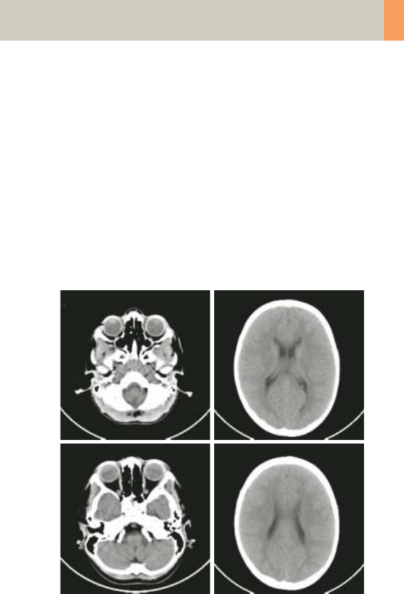
Children
197
Hints
• Use this protocol for children below 6 months of age.
• When bone structure is of interest, use kernel C60s
for image reconstruction.
• In order to optimize image quality versus radiation
dose, scans are provided within a maximum scan
field of 300 mm with respect to the iso-center. No
recon job with a field of view exceeding those limits
will be possible. Therefore, patient positioning has to
be performed accurately to ensure a centered loca-
tion of the skull.
C2-025.630.01.01.02_APPLICATIONGUIDE_SPIRIT.book Page 197 Friday, April 8, 2005 9:55 AM

198
Children
HeadSeq_Child
Indications:
Sequential mode for routine head studies for children,
e.g., tumors, hydrocephalus, hemorrhaging, abnor-
malities, etc.
A range of 8.25 cm is predefined.
* The conversion factor for a 7-year-old child, and a
scan range of 82.5 mm was used.
HeadSeq
kV 130
Effective mAs 120
Rotation time 1.5 sec
Slice collimation 2.5 mm
Slice width 2.5 mm
Feed/Scan 5.0 mm
Kernel C30s
CTDIVol 27.32 mGy
Effective dose Male: 1.09 mSv*
Female: 1.18 mSv*
Contrast medium IV injection
Start delay exam dependent
Flow rate dependent upon needle size/
Access site
Total amount 1 – 2 ml per kg of body weight
C2-025.630.01.01.02_APPLICATIONGUIDE_SPIRIT.book Page 198 Friday, April 8, 2005 9:55 AM
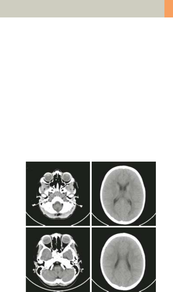
Children
199
Hints
• Children, who are more than 6 years old, should be
scanned with an adult protocol as the skull by this
time is fully grown.
• When bone structure is of interest, use kernel C60s
for image reconstruction.
• In order to optimize image quality versus radiation
dose, scans are provided within a maximum scan
field of 300 mm with respect to the iso-center. No
recon job with a field of view exceeding those limits
will be possible. Therefore, patient positioning has to
be performed accurately to ensure a centered loca-
tion of the skull.
• Please change the mAs value according to the age of
the child:
3 – 6 years 160 mAs.
C2-025.630.01.01.02_APPLICATIONGUIDE_SPIRIT.book Page 199 Friday, April 8, 2005 9:55 AM
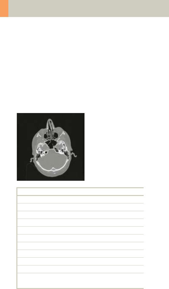
200
Children
InnerEar
Indications:
High Resolution Spiral mode for inner ear studies, e.g.,
malformations of the inner ear, inflammatory
changes, pathologies of the mastoid process, tumor
processes of the pyramids, post-traumatic changes,
etc.
A range of 2.5 cm will be covered in 22 sec.
* The conversion factor for a 7-year-old child, and a
scan range of 25 mm was used.
InnerEar
kV 80
Effective mAs 125
Rotation time 1.5 sec
Slice collimation 1.0 mm
Slice width 1.25 mm
Feed/Rotation 2.0 mm
Pitch Factor 1.0
Increment 1.0 mm
Kernel H80s
CTDIVol 8.09 mGy
Effective dose Male: 0.04 mSv*
Female: 0.04 mSv*
C2-025.630.01.01.02_APPLICATIONGUIDE_SPIRIT.book Page 200 Friday, April 8, 2005 9:55 AM

Children
201
Hints
• Children, who are more than 6 years old, should be
scanned with an adult protocol as the skull by this
time is fully grown.
• When soft tissue is of interest, use kernel H31s for
image reconstruction.
• In order to optimize image quality versus radiation
dose, scans are provided within a maximum scan
field of 300 mm with respect to the iso-center. No
recon job with a field of view exceeding those limits
will be possible. Therefore, patient positioning has to
be performed accurately to ensure a centered loca-
tion of the skull.
• Please change the mAs value according to the age of
the child:
3 – 6 years 160 mAs.
C2-025.630.01.01.02_APPLICATIONGUIDE_SPIRIT.book Page 201 Friday, April 8, 2005 9:55 AM
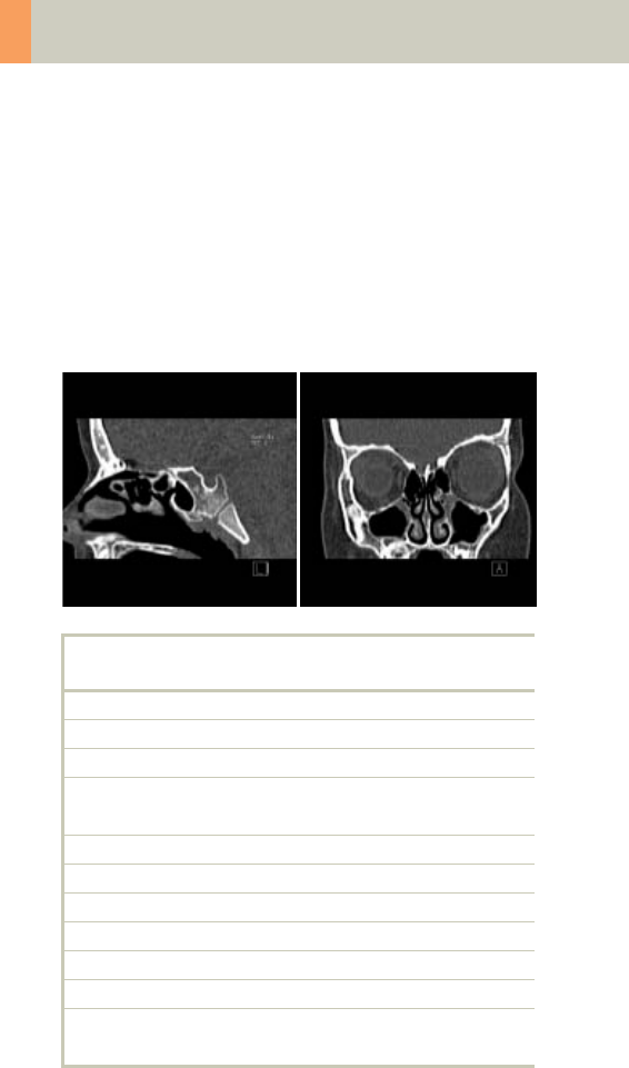
202
Children
SinusOrbi
Indications:
Spiral mode for routine spiral studies of the sinuses
and paranasal sinuses, e.g., sinusitis, pneumatization,
polyposis, malformations, tumors etc.
A range of 4 cm will be covered in 22 sec.
* The conversion factor for a 7-year-old child, and a
scan range of 40 mm was used.
SinusOrbi 2nd
reconstruction
kV 80
Effective mAs 81
Rotation time 1.0 sec
Slice
collimation
1.0 mm
Slice width 3.0 mm 1.25 mm
Feed/Rotation 2.0 mm
Pitch Factor 1.0
Increment 3.0 mm 0.8 mm
Kernel C60s C60s
CTDIVol 5.24 mGy
Effective dose Male: 0.03 mSv*
Female: 0.04 mSv*
C2-025.630.01.01.02_APPLICATIONGUIDE_SPIRIT.book Page 202 Friday, April 8, 2005 9:55 AM

Children
203
Hints
• Children, who are more than 6 years old, should be
scanned with an adult protocol.
• In order to optimize image quality versus radiation
dose, scans are provided within a maximum scan
field of 300 mm with respect to the iso-center. No
recon job with a field of view exceeding those limits
will be possible. Therefore, patient positioning has to
be performed accurately to ensure a centered loca-
tion of the skull.
• Please change the mAs value according to the age of
the child:
3 – 6 years 100 mAs.
Contrast medium IV injection
Start delay exam dependent
Flow rate dependent upon needle size/
Access site
Total amount 1 – 2 ml per kg of body weight
C2-025.630.01.01.02_APPLICATIONGUIDE_SPIRIT.book Page 203 Friday, April 8, 2005 9:55 AM

204
Children
Neck
Indications:
Spiral mode for routine neck studies, e.g., tumors, lym-
phoma, abscesses, etc.
A range of 15 cm will be covered in 19 sec.
* The conversion factor for a 7-year-old child, and a
scan range of 150 mm was used.
Neck
kV 130
Effective mAs 26
Rotation time 1.0 sec
Slice collimation 2.5 mm
Slice width 5.0 mm
Feed/Rotation 9.0 mm
Pitch Factor 1.8
Increment 5.0 mm
Kernel B50s
CTDIVol 2.80 mGy
Effective dose Male: 2.40 mSv*
Female: 2.52 mSv*
Contrast medium IV injection
Start delay exam dependent
Flow rate dependent upon needle size/
Access site
Total amount 1 – 2 ml per kg of body weight
C2-025.630.01.01.02_APPLICATIONGUIDE_SPIRIT.book Page 204 Friday, April 8, 2005 9:55 AM
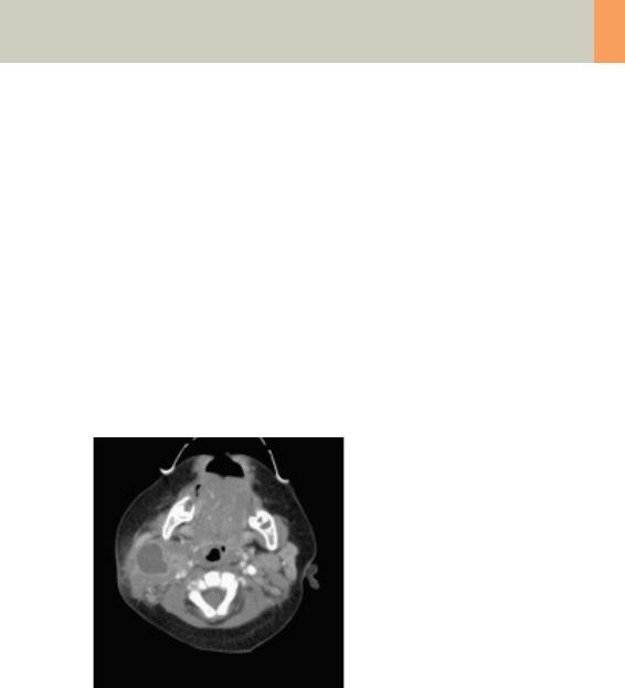
Children
205
Hints
• If necessary, scan down to the aortic arch or medi-
astinum to include the entire lesion.
• Cooperative children can be instructed to hold their
breath during the acquisition.
• Children, who are more than 6 years old should be
scanned with an adult protocol.
• Please change the mAs value according to the age of
the child:
3 – 6 years 39 mAs.
C2-025.630.01.01.02_APPLICATIONGUIDE_SPIRIT.book Page 205 Friday, April 8, 2005 9:55 AM

206
Children
ThoraxRoutine_Baby
Indications:
Spiral mode for routine thorax studies, e.g., pneumo-
nia, tumors, metastases, lymphoma, vascular abnor-
malities etc.
A range of 15 cm will be covered in 17 sec.
C2-025.630.01.01.02_APPLICATIONGUIDE_SPIRIT.book Page 206 Friday, April 8, 2005 9:55 AM

Children
207
* The conversion factor for an 8-week-old child, and a
scan range of 150 mm was used.
Hints
• Use this protocol for children below 35 kg.
• The first and second recon jobs are defined for visu-
alization of the mediastinum and the lungs, respec-
tively.
• Please change the mAs value according to the
weight of the child:
25 – 34 kg 60 mAs.
ThorRoutine 2nd
reconstruction
kV 80
Effective mAs 41
Rotation time 1.0 sec
Slice
collimation
2.5 mm
Slice width 5.0 mm 5.0 mm
Feed/Rotation 10.0 mm
Pitch Factor 2.0
Increment 5.0 mm 5.0 mm
Kernel B41s B60s
CTDIVol 1.13 mGy
Effective dose Male: 1.55 mSv*
Female: 1.85 mSv*
Contrast medium IV injection
Start delay exam dependent
Flow rate dependent upon needle size/
Access site
Total amount 1 – 2 ml per kg of body weight
C2-025.630.01.01.02_APPLICATIONGUIDE_SPIRIT.book Page 207 Friday, April 8, 2005 9:55 AM
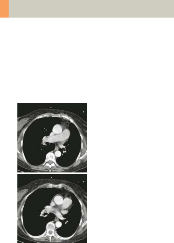
208
Children
ThoraxRoutine_Child
Indications:
Spiral mode for routine thorax studies, e.g., pneumo-
nia, tumors, metastases, lymphoma, vascular abnor-
malities etc.
A range of 15 cm will be covered in 17 sec.
C2-025.630.01.01.02_APPLICATIONGUIDE_SPIRIT.book Page 208 Friday, April 8, 2005 9:55 AM

Children
209
* The conversion factor for a 7-year-old child, and a
scan range of 150 mm was used.
Hints
• Children with a body weight of more than 55 kg
should be examined with an adult protocol.
• The first and second recon jobs are defined for visu-
alization of the mediastinum and the lungs, respec-
tively.
• Please change the mAs value according to the
weight of the child:
45 – 54 kg 37 mAs.
ThorRoutine 2nd
reconstruction
kV 130
Effective mAs 26
Rotation time 1.0 sec
Slice
collimation
2.5 mm
Slice width 5.0 mm 5.0 mm
Feed/Rotation 10.0 mm
Pitch Factor 2.0
Increment 5.0 mm 5.0 mm
Kernel B41s B60s
CTDIVol 2.80 mGy
Effective dose Male: 1.46 mSv*
Female: 1.72 mSv*
Contrast medium IV injection
Start delay exam dependent
Flow rate dependent upon needle size/
Access site
Total amount 1 – 2 ml per kg of body weight
C2-025.630.01.01.02_APPLICATIONGUIDE_SPIRIT.book Page 209 Friday, April 8, 2005 9:55 AM

210
Children
ThoraxHRSeq_Baby
Indications:
Sequence mode for High Resolution lung studies, e.g.,
interstitial changes of the lung parenchyma, etc.
A range of 20.1 cm is predefined.
* The conversion factor for an 8-week-old child, and a
scan range of 201 mm was used.
ThorHRSeq
kV 80
Effective mAs 90
Rotation time 1.0 sec
Slice collimation 1.0 mm
Slice width 1.0 mm
Feed/Scan 10.0 mm
Kernel U90s
CTDIVol 0.50 mGy
Effective dose Male: 0.88 mSv*
Female: 1.06 mSv*
C2-025.630.01.01.02_APPLICATIONGUIDE_SPIRIT.book Page 210 Friday, April 8, 2005 9:55 AM
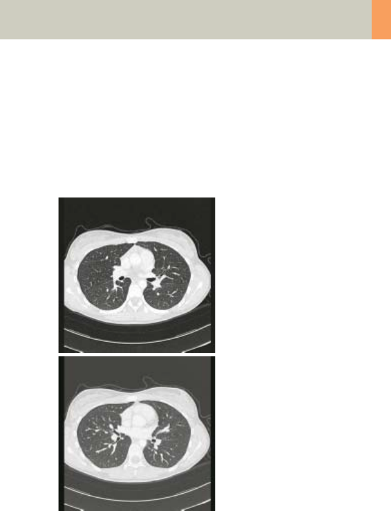
Children
211
Hints
• Use this protocol for children below 35 kg.
• If you want to acquire the patient at full inspiration
or full expiration, you should practice the breathing
with the patient a few times before beginning the
scan, so that reproducibility may be improved.
C2-025.630.01.01.02_APPLICATIONGUIDE_SPIRIT.book Page 211 Friday, April 8, 2005 9:55 AM

212
Children
ThoraxHRSeq_Child
Indications:
Sequence mode for High Resolution lung studies, e.g.,
interstitial changes of the lung parenchyma, etc.
A range of 20.1 cm is predefined.
* The conversion factor for a 7-year-old child, and a
scan range of 201 mm was used.
ThorHRSeq
kV 130
Effective mAs 70
Rotation time 1.0 sec
Slice collimation 1.0 mm
Slice width 1.0 mm
Feed/Scan 10.0 mm
Kernel U90s
CTDIVol 1.51 mGy
Effective dose Male: 1.02 mSv*
Female: 1.21 mSv*
C2-025.630.01.01.02_APPLICATIONGUIDE_SPIRIT.book Page 212 Friday, April 8, 2005 9:55 AM
Children
213
Hints
• Children with a body weight of more than 55 kg
should be examined with an adult protocol.
• If you want to acquire the patient at full inspiration
or full expiration, you should practice the breathing
with the patient a few times before beginning the
scan, so that reproducibility may be improved.
C2-025.630.01.01.02_APPLICATIONGUIDE_SPIRIT.book Page 213 Friday, April 8, 2005 9:55 AM

214
Children
Abdomen_Baby
Indications:
Spiral mode for routine studies in the region of abdo-
men and pelvis, e.g., tumors, lymphoma, abscesses,
post-traumatic changes, etc.
A range of 30 cm will be covered in 32 sec.
* The conversion factor for an 8-week-old child, and a
scan range of 300 mm was used.
Abdomen
kV 80
Effective mAs 41
Rotation time 1.0 sec
Slice collimation 2.5 mm
Slice width 5.0 mm
Feed/Rotation 10.0 mm
Pitch Factor 2.0
Increment 5.0 mm
Kernel B41s
CTDIVol 1.13 mGy
Effective dose Male: 3.26 mSv*
Female: 5.05 mSv*
Contrast medium IV injection
Start delay exam dependent
Flow rate dependent upon needle size/
Access site
Total amount 1 – 2 ml per kg of body weight
C2-025.630.01.01.02_APPLICATIONGUIDE_SPIRIT.book Page 214 Friday, April 8, 2005 9:55 AM
Children
215
Hints
• Use this protocol for children below 35 kg.
• Delayed scans may be required for the kidneys and
bladder.
• Rectal contrast may be required for evaluation of pel-
vic mass.
• Please change the mAs value according to the
weight of the child:
25 – 34 kg 70 mAs.
C2-025.630.01.01.02_APPLICATIONGUIDE_SPIRIT.book Page 215 Friday, April 8, 2005 9:55 AM

216
Children
Abdomen_Child
Indications:
Spiral mode for routine studies in the region of abdo-
men and pelvis, e.g., tumors, lymphoma, abscesses,
post-traumatic changes, etc.
A range of 30 cm will be covered in 32 sec.
* The conversion factor for a 7-year-old child, and a
scan range of 300 mm was used.
Abdomen
kV 130
Effective mAs 41
Rotation time 1.0 sec
Slice collimation 2.5 mm
Slice width 5.0 mm
Feed/Rotation 10.0 mm
Pitch Factor 2.0
Increment 5.0 mm
Kernel B41s
CTDIVol 4.42 mGy
Effective dose Male: 4.83 mSv*
Female: 7.40 mSv*
Contrast medium IV injection
Start delay exam dependent
Flow rate dependent upon needle size/
Access site
Total amount 1 – 2 ml per kg of body weight
C2-025.630.01.01.02_APPLICATIONGUIDE_SPIRIT.book Page 216 Friday, April 8, 2005 9:55 AM
Children
217
Hints
• Delayed scans may be required for the kidneys and
bladder.
• Rectal contrast may be required for evaluation of pel-
vic mass.
• Children with a body weight of more than 55 kg
should be examined with an adult protocol.
C2-025.630.01.01.02_APPLICATIONGUIDE_SPIRIT.book Page 217 Friday, April 8, 2005 9:55 AM

218
Children
Spine_Baby
Indications:
Spiral mode for spine studies, e.g., post-traumatic
changes, tumors, malformations, orthopedic indica-
tions, etc.
A range of 15 cm will be covered in 32 sec.
* The conversion factor for an 8-week-old child, and a
scan range of 150 mm was used.
Spine 2nd
reconstruction
kV 80
Effective mAs 110
Rotation time 1.0 sec
Slice
collimation
2.5 mm
Slice width 3.0 mm 3.0 mm
Feed/Rotation 5.0 mm
Pitch Factor 1.0
Increment 3.0 mm 2.0 mm
Kernel B41s B60s
CTDIVol 3.03 mGy
Effective dose Male:
1.90 mSv*
Female:
4.06 mSv*
C2-025.630.01.01.02_APPLICATIONGUIDE_SPIRIT.book Page 218 Friday, April 8, 2005 9:55 AM
Children
219
Hints
• Use this protocol for children below 35 kg.
• Please change the mAs value according to the
weight of the child:
25 – 34 kg 160 mAs.
C2-025.630.01.01.02_APPLICATIONGUIDE_SPIRIT.book Page 219 Friday, April 8, 2005 9:55 AM

220
Children
Spine_Child
Indications:
Spiral mode for spine studies, e.g., post-traumatic
changes, tumors, malformations, orthopedic indica-
tions, etc.
A range of 15 cm will be covered in 32 sec.
* The conversion factor for a 7-year-old child, and a
scan range of 150 mm was used.
Spine 2nd
reconstruction
kV 130
Effective mAs 70
Rotation time 1.0 sec
Slice
collimation
2.5 mm
Slice width 3.0 mm 3.0 mm
Feed/Rotation 5.0 mm
Pitch Factor 1.0
Increment 3.0 mm 2.0 mm
Kernel B41s B60s
CTDIVol 7.55 mGy
Effective dose Male:
1.79 mSv*
Female:
3.78 mSv*
C2-025.630.01.01.02_APPLICATIONGUIDE_SPIRIT.book Page 220 Friday, April 8, 2005 9:55 AM
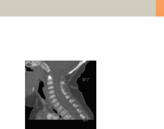
Children
221
Hint
• Children with a body weight of more than 55 kg
should be examined with an adult protocol.
C2-025.630.01.01.02_APPLICATIONGUIDE_SPIRIT.book Page 221 Friday, April 8, 2005 9:55 AM

222
Children
ExtrHR_Baby
Indications:
Spiral mode for high resolution extremity studies, e.g.,
post-traumatic changes, tumors, malformations, etc.
A range of 10 cm will be covered in 27 sec.
* The conversion factor for an 8-week-old child, and a
scan range of the knee of 100 mm was used.
ExtrHR
kV 80
Effective mAs 50
Rotation time 1.0 sec
Slice collimation 1.0 mm
Slice width 1.25 mm
Feed/Rotation 4.0 mm
Pitch Factor 2.0
Increment 0.8 mm
Kernel B70s
CTDIVol 1.38 mGy
Effective dose Male: < 0.01 mSv*
Female: < 0.01 mSv*
C2-025.630.01.01.02_APPLICATIONGUIDE_SPIRIT.book Page 222 Friday, April 8, 2005 9:55 AM

Children
223
Hints
• Use this protocol for children below 35 kg.
• Please change the mAs value according to the
weight of the child:
15 – 34 kg 80 mAs.
C2-025.630.01.01.02_APPLICATIONGUIDE_SPIRIT.book Page 223 Friday, April 8, 2005 9:55 AM

224
Children
ExtrHR_Child
Indications:
Spiral mode for bone studies, e.g., tumors, post-
traumatic changes, orthopedic indications, etc.
A range of 10 cm will be covered in 27 sec.
* The conversion factor for a 7-year-old child, and a
scan range of the knee of 100 mm was used.
ExtrHR
kV 130
Effective mAs 40
Rotation time 1.0 mm
Slice collimation 1.0 mm
Slice width 1.25 mm
Feed/Rotation 4.0 mm
Pitch Factor 2.0
Increment 0.8 mm
Kernel B70s
CTDIVol 4.31 mGy
Effective dose Male: < 0.01 mSv*
Female: < 0.01 mSv*
Contrast medium IV injection
Start delay exam dependent
Flow rate dependent upon needle size/
Access site
Total amount 1 – 2 ml per kg of body weight
C2-025.630.01.01.02_APPLICATIONGUIDE_SPIRIT.book Page 224 Friday, April 8, 2005 9:55 AM
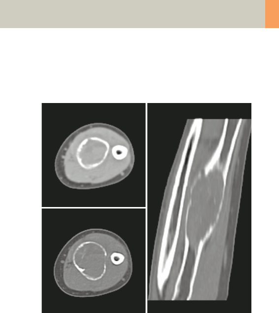
Children
225
Hint
• Children with a body weight of more than 55 kg
should be examined with an adult protocol.
C2-025.630.01.01.02_APPLICATIONGUIDE_SPIRIT.book Page 225 Friday, April 8, 2005 9:55 AM

226
Children
HeadAngio
Indications:
Spiral mode for head CT angiography, e.g., cerebral
vascular abnormalities, tumors etc.
A range of 6 cm will be covered in 32 sec.
* The conversion factor for a 7-year-old child, and a
scan range of 60 mm was used.
HeadAngio 2nd reconstruction
kV 80
Effective mAs 81
Rotation time 1.0 sec
Slice
collimation
1.0 mm
Slice width 2.0 mm 1.25 mm
Feed/Rotation 2.0 mm
Pitch Factor 1.0
Increment 2.0 mm 0.8 mm
Kernel C30s C30s
CTDIVol 5.24 mGy
Effective dose Male:
0.12 mSv*
Female:
0.13 mSv*
Contrast medium IV injection
Start delay exam dependent
Flow rate dependent upon needle size/
Access site
Total amount 1 – 2 ml per kg of body weight
C2-025.630.01.01.02_APPLICATIONGUIDE_SPIRIT.book Page 226 Friday, April 8, 2005 9:55 AM

Children
227
Hints
• Children, who are more than 12 years old, should be
scanned with an adult protocol as the skull by this
time is fully grown.
• CARE Bolus may be used to optimize the bolus timing
with a triggering threshold of 120 HU, or use manual
triggering.
• An advanced algorithm allows for improved head
image quality, without any additional post-process-
ing.
C2-025.630.01.01.02_APPLICATIONGUIDE_SPIRIT.book Page 227 Friday, April 8, 2005 9:55 AM

228
Children
HeadAngio08s
Indications:
Spiral mode for head CT angiography, e.g., cerebral
vascular abnormalities, tumors etc.
A range of 6 cm will be covered in 26 sec.
* The conversion factor for a 7-year-old child, and a
scan range of 60 mm was used.
HeadAngio 2nd
reconstruction
kV 80
Effective mAs 65
Rotation time 0.8 sec
Slice
collimation
1.0 mm
Slice width 2.0 mm 1.25 mm
Feed/Rotation 2.0 mm
Pitch Factor 1.0
Increment 2.0 mm 0.8 mm
Kernel C30s C30s
CTDIVol 4.21 mGy
Effective dose Male:
0.10 mSv*
Female:
0.10 mSv*
C2-025.630.01.01.02_APPLICATIONGUIDE_SPIRIT.book Page 228 Friday, April 8, 2005 9:55 AM

Children
229
Hints
• Please change the mAs value according to the age of
the child:
6 – 12 years 80 mAs.
• Children, who are more than 12 years old, should be
scanned with an adult protocol as the skull by this
time is fully grown
C2-025.630.01.01.02_APPLICATIONGUIDE_SPIRIT.book Page 229 Friday, April 8, 2005 9:55 AM

230
Children
CarotidAngio
Indications:
Spiral mode for the carotid arteries, e.g., carotid steno-
sis or occlusion, vascular abnormalities of the carotids
or vertebral arteries, etc.
A range of 10 cm will be covered in 27 sec.
* The conversion factor for a 7-year-old child, and a
scan range of 100 mm was used.
CarotidAngio 2nd reconstr.
kV 80
Effective mAs 50
Rotation time 1.0 sec
Slice
collimation
1.0 mm
Slice width 3.0 mm 1.25 mm
Feed/Rotation 4.0 mm
Pitch Factor 2.0
Increment 3.0 mm 0.8 mm
Kernel B41s B41s
CTDIVol 1.38 mGy
Effective dose Male:
0.50 mSv*
Female:
0.50 mSv*
Contrast medium IV injection
Start delay exam dependent
Flow rate dependent upon needle size/
Access site
Total amount 1 – 2 ml per kg of body weight
C2-025.630.01.01.02_APPLICATIONGUIDE_SPIRIT.book Page 230 Friday, April 8, 2005 9:55 AM
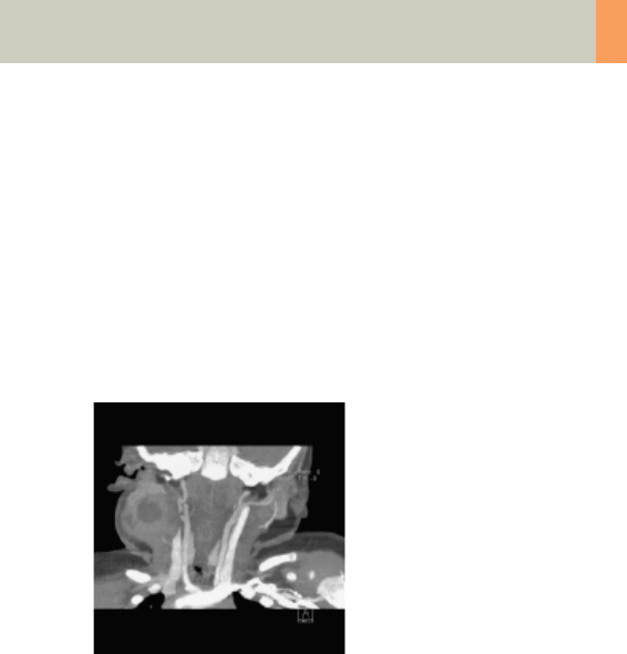
Children
231
Hints
• Please change the mAs value according to the age of
the child:
6 – 12 years 75 mAs.
• Children, who are more than 12 years old should be
scanned with an adult protocol.
• CARE Bolus may be used to optimize the bolus timing
with a triggering threshold of 120 HU, or use manual
triggering.
C2-025.630.01.01.02_APPLICATIONGUIDE_SPIRIT.book Page 231 Friday, April 8, 2005 9:55 AM

232
Children
CarotidAngio08s
Indications:
Spiral mode for the carotid arteries, e.g., carotid steno-
sis or occlusion, vascular abnormalities of the carotids
or vertebral arteries, etc.
A range of 10 cm will be covered in 22 sec.
* The conversion factor for a 7-year-old child, and a
scan range of 100 mm was used.
CarotidAngio 2nd reconstr.
kV 80
Effective mAs 50
Rotation time 0.8 sec
Slice
collimation
1.0 mm
Slice width 3.0 mm 1.25 mm
Feed/Rotation 4.0 mm
Pitch Factor 2.0
Increment 3.0 mm 0.8 mm
Kernel B41s B41s
CTDIVol 1.38 mGy
Effective dose Male:
0.50 mSv*
Female:
0.50 mSv*
Contrast medium IV injection
Start delay exam dependent
Flow rate dependent upon needle size/
Access site
Total amount 1 – 2 ml per kg of body weight
C2-025.630.01.01.02_APPLICATIONGUIDE_SPIRIT.book Page 232 Friday, April 8, 2005 9:55 AM

Children
233
Hints
• Please change the mAs value according to the age of
the child:
6 – 12 years 75 mAs.
• Children, who are more than 12 years old should be
scanned with an adult protocol.
• CARE Bolus may be used to optimize the bolus timing
with a triggering threshold of 120 HU, or use manual
triggering.
C2-025.630.01.01.02_APPLICATIONGUIDE_SPIRIT.book Page 233 Friday, April 8, 2005 9:55 AM

234
Children
BodyAngio
Indications:
Spiral mode for abdominal CT Angio studies, e.g., vas-
cular abnormalities, aneurysms, etc.
A range of 10 cm will be covered in 19 sec.
* The conversion factor for a 7-year-old child, and a
scan range of 100 mm was used.
BodyAngio 2nd reconstr.
kV 80
Effective mAs 41
Rotation time 1.0 sec
Slice
collimation
1.5 mm
Slice width 3.0 mm 2.0 mm
Feed/Rotation 6.0 mm
Pitch Factor 2.0
Increment 3.0 mm 1.5 mm
Kernel B41s B41s
CTDIVol 1.13 mGy
Effective dose Male:
0.73 mSv*
Female:
0.84 mSv*
Contrast medium IV injection
Start delay exam dependent
Flow rate dependent upon needle size/
Access site
Total amount 1 – 2 ml per kg of body weight
C2-025.630.01.01.02_APPLICATIONGUIDE_SPIRIT.book Page 234 Friday, April 8, 2005 9:55 AM

Children
235
Hints
• Please change the mAs value according to the
weight of the child:
35 – 44 kg 45 mAs
45 – 54 kg 60 mAs.
• Children with a body weight of more than 55 kg
should be examined with an adult protocol.
• CARE Bolus may be used to optimize the bolus tim-
ing. Set the ROI for the monitoring scan in the
abdominal aorta with triggering threshold of 120
HU, or use manual triggering.
C2-025.630.01.01.02_APPLICATIONGUIDE_SPIRIT.book Page 235 Friday, April 8, 2005 9:55 AM

236
Children
BodyAngio08s
Indications:
Spiral mode for abdominal CT Angio studies, e.g., vas-
cular abnormalities, aneurysms, etc.
A range of 10 cm will be covered in 15 sec.
* The conversion factor for a 7-year-old child, and a
scan range of 100 mm was used.
BodyAngio 2nd reconstr.
kV 80
Effective mAs 35
Rotation time 0.8 sec
Slice
collimation
1.5 mm
Slice width 3.0 mm 2.0 mm
Feed/Rotation 6.0 mm
Pitch Factor 2.0
Increment 3.0 mm 1.5 mm
Kernel B41s B41s
CTDIVol 0.96 mGy
Effective dose Male:
0.62 mSv*
Female:
0.72 mSv*
C2-025.630.01.01.02_APPLICATIONGUIDE_SPIRIT.book Page 236 Friday, April 8, 2005 9:55 AM

Children
237
Hints
• Please change the mAs value according to the
weight of the child:
35 – 44 kg 45 mAs
45 – 54 kg 60 mAs.
• Children with a body weight of more than 55 kg
should be examined with an adult protocol.
C2-025.630.01.01.02_APPLICATIONGUIDE_SPIRIT.book Page 237 Friday, April 8, 2005 9:55 AM

238
Children
NeonateBody
Indications:
Spiral mode for routine neonate body studies, e.g.,
tumors, abnormalities, malformations, abscesses, etc.
A range of 15 cm will be covered in 17 sec.
* The conversion factor for a 7-year-old child, and a
scan range of 150 mm was used.
NeonateBody
kV 80
Effective mAs 41
Rotation time 1.0 sec
Slice collimation 2.5 mm
Slice width 5.0 mm
Feed/Rotation 10.0 mm
Pitch Factor 2.0
Increment 5.0 mm
Kernel B41s
CTDIVol 1.13
Effective dose Male: 1.59 mSv*
Female: 2.01 mSv*
Contrast medium IV injection
Start delay exam dependent
Flow rate dependent upon needle size/
Access site
Total amount 1 – 2 ml per kg of body weight
C2-025.630.01.01.02_APPLICATIONGUIDE_SPIRIT.book Page 238 Friday, April 8, 2005 9:55 AM
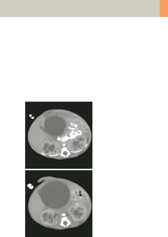
Children
239
Hints
• Use this protocol for children below 1 month of age.
• CARE Bolus may be used to optimize the bolus tim-
ing. Set the ROI for the monitoring scan in the
abdominal aorta with triggering threshold of 120
HU, or use manual triggering.
• You can modify the slice width for image reconstruc-
tion according to the clinical indications.
C2-025.630.01.01.02_APPLICATIONGUIDE_SPIRIT.book Page 239 Friday, April 8, 2005 9:55 AM

240
syngo 3D
The 3D card offers the possibility to combine two-
dimensional images to form three-dimensional views.
To do this, the 3D card provides you with the following
methods:
Multi Planar Reconstruction (MPR)
Interactive navigation through 3D volumes in arbitrary
orientations.
• Orthogonal, oblique or double-oblique orientation.
• Easy scrolling through 3D volume data set.
• Real-time reconstruction of secondary slices.
• Additional diagnostic information, e.g., with sagittal
or coronal reconstructions from axial images.
• Variable slice thickness (MPR Thick, MPR) and dis-
tance with configurable default values.
• Calculation of arbitrarily curved cuts.
Maximum Intensity Projection (MIP)
Angiographic display.
• Projection of pixels with highest intensity (vascular
information) onto an arbitrarily oriented plane.
• Display of e.g., aneurysms, plaques, stenoses and
other vascular anomalies.
• MIP Thin function for projection within a small slab
to focus on particular vascular structure.
C2-025.630.01.01.02_APPLICATIONGUIDE_SPIRIT.book Page 240 Friday, April 8, 2005 9:55 AM

syngo 3D
241
Shaded Surface Display (SSD)
Surface display of complex anatomies.
• 3D display of surfaces from a series of contiguous
slices using a variable threshold.
• The displayed volume consist of voxels whose HU are
in a range defined by two limit values, an upper and
a lower threshold (= HU limits).
• Display and analyze various anatomy, e.g., from the
cranium, pelvis, extremities, e.g., for the purpose of
planning surgical interventions.
• The 3D objects can be tilted and rotated in real-time.
Volume Rendering Technique (VRT)
True 3D visualization of volume data.
• Projection onto an arbitrarily oriented plane.
• Density, opacity and refraction information is used to
generate views that optimally meet different clinical
objectives.
• Optimal display quality and differentiation of differ-
ent organs through independent control of color,
opacity and shading in up to 4 tissue classes.
• Predefined settings for many clinical objectives and
anatomic regions are easily selected from an image
gallery.
• Pre-settings can be linked to DICOM series descrip-
tion to automatically ensure standardized quality in
clinical routine.
• Clip-planes can be used to easily scroll through the
volume in VRT Thin mode.
• Easy interaction with SmartSelect control (right
mouse button).
C2-025.630.01.01.02_APPLICATIONGUIDE_SPIRIT.book Page 241 Friday, April 8, 2005 9:55 AM

242
syngo 3D
Prerequisites
At least 3 and maximum of 1600 images must have
been loaded to process 3D; (with more than 1600
images the series will be split up). All images must
have the same x/y coordinates and FoV.
• You should close any data sets that you no longer
need in order to release memory space and maintain
application performance.
• CT volume data sets are best acquired with overlap-
ping thin slice CT technique.
Workflow
Loading the Images
After loading the images into syngo 3D the following
layout is displayed:
C2-025.630.01.01.02_APPLICATIONGUIDE_SPIRIT.book Page 242 Friday, April 8, 2005 9:55 AM

syngo 3D
243
Image Representation on the 3D Card
The image area on the 3D card is divided into four seg-
ments:
– Reference segment (sagittal view)
– Reference segment (coronal view)
– Reference segment (transversal view)
– Output segment
The first three segments are reference segments, the
fourth segment is an output segment. In the three ref-
erence segments the images are first shown in the
views that are parallel and perpendicular to the direc-
tion of scanning.
By turning and moving the views you can define the
position and orientation of the plane that is to be used
as the reference image for the reconstruction of
images or series.
The reference segments are used to display different
views of the volume data set, while the reference dis-
play (the view) is used as a reference for a 3D-recon-
struction.
The images and series generated by various tools on
the basis of the reference image are displayed in the
output segment.
To find the best suitable reference image for planning
reconstruction of images and series, you can freely
rotate and move all three views.
C2-025.630.01.01.02_APPLICATIONGUIDE_SPIRIT.book Page 243 Friday, April 8, 2005 9:55 AM

244
syngo 3D
Defining Output Types
You can change the output type for a segment at any
time, i.e., from Multi Planar Reconstruction (MPR) to
Maximum Intensity Projection (MIP), to Shaded Sur-
face Display (SSD), or to Volume Rendering Technique
(VRT).
Depending on your working method, you will first gen-
erate a reference image, for example, in MPR in the
desired view and then switch to MIP, SSD or VRT dis-
play.
• Click on the segment for which you want to change
the output type.
• If you want to switch over all segments, you must
select and switch over each one separately, one after
the other.
Creating Series
This application gives you the ability to easily create
new images or even image series, e.g., for fast display
of interesting anatomical structures
• With any slice thickness (at least the reconstructed
slice thickness)
• Variable distance/angle between the images
• Selectable number of images
• Selectable range of reconstruction
• Different output types
Parallel Ranges
With this option you generate series of cut images that
are parallel to one another and perpendicular to the
reference image for the output types MPR, MPR Thick,
MIP Thin and VRT Thin.
For example, for MPRs or MIP Thin through a process in
the lung or abdomen.
C2-025.630.01.01.02_APPLICATIONGUIDE_SPIRIT.book Page 244 Friday, April 8, 2005 9:55 AM

syngo 3D
245
Radial Ranges
For output types MPR, MPR Thick and MIP Thin you
generate a series of cut images arranged in a star
shape.
For output types MIP, SSD and VRT you generate a
series of projections and views of the volume each
rotated around a defined angle. In this way, you simu-
late a step-by-step rotation.
For example, for colored VRT images, showing a pro-
cess from different angles.
Expanded Ranges
With this option you generate images that are located
in front of or behind the reference image. This option,
too, is only available for output types MPR, MPR Thick
or MIP Thin.
For example, for MPRs or MIP Thin through a process in
the lung or abdomen.
Curved Ranges
If you want to view sub-areas that cannot be obtained
by planar, i.e., flat images, you can draw a cut line with
any curvature freehand. This cut will then be shown as
an image/series in the output segment.
For example, for MPRs or MIP Thin from the aorta or
the peripheral arteries.
C2-025.630.01.01.02_APPLICATIONGUIDE_SPIRIT.book Page 245 Friday, April 8, 2005 9:55 AM

246
syngo 3D
Editing
A common problem in evaluating medical images is
that areas relevant to an examination are hidden by
other structures, especially bones. The necessary
image information is contained in the volume data set
but must be made visible with suitable editing steps.
1. VOI mode: With a Volume of Interest (VOI), you
extract a volume of diagnostic interest by limiting
the volume to be reconstructed to a partial volume.
You can extract a VOI (volume of interest) in one of the
following ways:
• Position and differentiate a cuboid VOI (VOI Clipbox)
• Draw a freehand VOI (VOI Punch Mode)
2. Clip planes: Clip planes can also be used for hiding
parts of the data set.
Sometimes it is useful to use only a part of the volume
for projection. The sub area is defined by the two par-
allel intersection planes (“separation plane“). The dis-
tance between these planes is the slice thickness to be
defined. For example, you can avoid cutting out inter-
fering structures; (MIP Thin, VRT Thin/Clip).
C2-025.630.01.01.02_APPLICATIONGUIDE_SPIRIT.book Page 246 Friday, April 8, 2005 9:55 AM

syngo 3D
247
3. 3D Object Editor: Easy elimination of obstructing
information.
• Easy volume confinement with clip-box or variable
editing slab.
• Fast object creation with threshold operations or
automatic volume growing.
• Multiple editor objects can be displayed with differ-
ently colored SSD.
• Complete object subtraction with dilatation and ero-
sion functions.
• Remaining volume data set after object subtraction
can be displayed with all 3D representations, i.e.
VRT, MPR, MIP or SSD.
• With the 3D Object Editor you can perform the fol-
lowing operations:
– Object generation with Region Growing
– Object management in the object list
– Object editing with Object Punching and
Morphological Operations
C2-025.630.01.01.02_APPLICATIONGUIDE_SPIRIT.book Page 247 Friday, April 8, 2005 9:55 AM
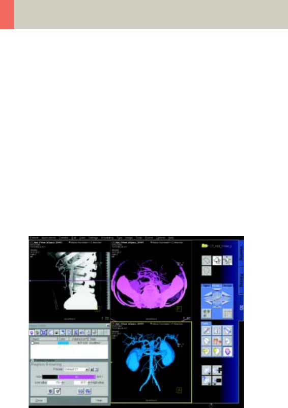
248
syngo 3D
Region Growing
Normally in the first step you will generate one or more
“objects“ from the volume data set originally loaded in
3D. By specifying a limited voxel value range you
extract only a section of the voxels from the original
data set. In this way, you generate an object in the
result segment.
Instead of extracting globally from the entire volume
data set, you can also proceed “slice by slice“ (in 3D
blocks) using the Slab Editor.
You can also set Seed Points in the original data set,
thus limiting the creation of an object to defined
regions which are also connected to one another in the
specified voxel area.
Object Punching
C2-025.630.01.01.02_APPLICATIONGUIDE_SPIRIT.book Page 248 Friday, April 8, 2005 9:55 AM

syngo 3D
249
Like editing volume data sets in the VOI mode, you can
use the 3D Editor, too. You are provided with tools for
cutting out structures from an object that you have
previously generated.
Using the Slab Editor you can define your own cutting
depth.
Morphological Operations
In some cases it will not be simple to separate the
structures of an object using the cutting tools. Here we
recommend eroding or shrinking the areas of the
object by a specified surface thickness, until the
obscuring structures are no longer contained in the
object.
You can subsequently dilate or blow up the remaining
object areas by a defined surface thickness. As a result,
the irrelevant areas contained at the outset are now
removed from the representation.
If you perform the same operations in reverse order,
small cavities in the object will be filled.
Documentation of Results
The buttons Copy to Film sheet and Save/Save As are
always available. You can always document intermedi-
ate results by using these buttons.
To save images you have following possibilities:
• Storing the new series automatically during recon-
struction
•The Save button will store the image/series with no
further check
•The Save as button will give you the ability to choose
a name for the new the image/series before storing
C2-025.630.01.01.02_APPLICATIONGUIDE_SPIRIT.book Page 249 Friday, April 8, 2005 9:55 AM

250
syngo 3D
Workflow for a CT Extremity
Examination
Using MPR/MPR Thick
1. Load the series to MPR.
2. Manipulate the volume to evaluate anatomy:
a)Orientate the image volume for the best view of
the anatomy.
b)Adjust the window as necessary.
c) Pan and zoom image as necessary.
3. Scroll through the volume quickly using the 3D
cross-hair or dog-ears to gain a three-dimensional
impression.
4. The minimum slice thickness of an MPR image is one
voxel, but you can generate thicker slices (MPR
Thick) for easier evaluation.
5. Measure, annotate and document as needed.
6. Optionally, create image series using parallel,
expanded or curved ranges and output them either
on a film or save them to the database.
C2-025.630.01.01.02_APPLICATIONGUIDE_SPIRIT.book Page 250 Friday, April 8, 2005 9:55 AM

syngo 3D
251
Using SSD
1. Load the series to SSD.
Hint: Do not use a series with a high resolution ker-
nel, e.g., kernel 10 or 20 is recommended.
2. Manipulate the volume to evaluate anatomy:
a)Orientate the image volume for the best view of
the anatomy.
b)Adjust the threshold as necessary.
c)Pan and zoom image as necessary.
d)To eliminate unwanted structures, use VOI punch-
ing/3D Object Editor.
3. Measure, annotate and document as needed.
4. Optionally, create image series using radial ranges
and output them either on a film or save them to
the database.
Using VRT
1. Load the series to VRT.
2. Manipulate volume to evaluate anatomy:
a)Orientate the image volume for the best view of
the anatomy.
b)To eliminate unwanted structures, either activate
VRT Thin/Clip or use VOI punching/3D Object Edi-
tor.
c)Select a VRT preset from the VRT gallery.
d)Adjust window, opacity, color and lighting effects
as necessary.
e)Pan and zoom image as necessary.
3. Measure, annotate and document as needed.
4. Optionally, create image series using radial ranges
for VRT; parallel, expanded or curved ranges for VRT
Thin/Clip and output them either on a film or save
them to the database.
C2-025.630.01.01.02_APPLICATIONGUIDE_SPIRIT.book Page 251 Friday, April 8, 2005 9:55 AM

252
syngo 3D
Workflow for a CT
Angiography
Using MIP/MIP Thin
1. Load the series to MIP.
2. Manipulate the volume to evaluate anatomy:
a)Orientate the image volume for the best view of
the anatomy.
b)To eliminate unwanted bone, either activate MIP
Thin or use VOI punching/3D Object Editor.
c)Adjust the window as necessary.
d)Pan and zoom image as necessary.
3. Measure, annotate and document as needed.
4. Optionally, create image series using radial ranges
for MIP; parallel, expanded or curved ranges for MIP
Thin and output them either on a film or save them
to the database.
C2-025.630.01.01.02_APPLICATIONGUIDE_SPIRIT.book Page 252 Friday, April 8, 2005 9:55 AM

syngo 3D
253
Using VRT/VRT Thin/Clip
1. Load the series to VRT.
2. Manipulate volume to evaluate anatomy:
a)Orientate the image volume for the best view of
the anatomy.
b)To eliminate unwanted bone, either activate VRT
Thin/Clip or use VOI punching/3D Object Editor.
c)Select VRT preset from VRT gallery.
d)Adjust window, opacity, color and lighting effects
as necessary.
e)Pan and zoom image as necessary.
3. Measure, annotate and document as needed.
4. Optionally, create image series using radial ranges
for VRT; parallel, expanded or curved ranges for VRT
Thin/Clip and output them either on a film or save
them to the database.
C2-025.630.01.01.02_APPLICATIONGUIDE_SPIRIT.book Page 253 Friday, April 8, 2005 9:55 AM

254
syngo 3D
Hints in General
Setting Views in the Volume Data Set
Three-dimensional image processing allows you to cre-
ate images in any orientation and position within the
data volume.
You can "move" through the volume and rotate it in any
direction. Depending on the method you are using,
various aids are available to you.
Rotating around one axes (oblique cut planes)
For oblique slices, you rotate a slice about one axis of
the patient coordinate system starting from the stan-
dard view.
The orientation is displayed in the image as a combina-
tion of two orientation labels.
One of the two reference lines in the image is now dot-
ted. The corresponding plane is therefore oblique in
relation to the displayed image.
Rotating around two axis (double-oblique cut planes)
You obtain cut planes in two axes whenever you rotate
one slice around two different patient coordinate axes
one after the other.
C2-025.630.01.01.02_APPLICATIONGUIDE_SPIRIT.book Page 254 Friday, April 8, 2005 9:55 AM

syngo 3D
255
The plane is then no longer perpendicular to either of
the coordinate axes. The image orientation is displayed
as a combination of three orientation labels.
– The subtask card Orientation will always give you the
ability to return immediately back to the beginning
or to any standard view.
– View perpendicular to reference image (Ortho Sync).
Usually, you activate the orthogonal view to display
slices along the main axis of an organ, e.g., the
heart.
Changing /Creating VRT Presets
You will use the Volume Rendering Technique (VRT) to
obtain more precise representation and separation of
tissue types. To highlight certain aspects of the ana-
tomical region, you can change the color, brightness,
and transparency of different areas.
As display parameters for the VRT view, customary
default settings are stored on your system in the VRT
gallery.
C2-025.630.01.01.02_APPLICATIONGUIDE_SPIRIT.book Page 255 Friday, April 8, 2005 9:55 AM

256
syngo 3D
If the default settings are not appropriate for your diag-
nostic problem, you can alter them individually. In that
way you can emphasize the structures of interest in an
optimum way.
– Ramp and trapezoid manipulation: Ramps and trap-
ezoids are functions which define window and ren-
dering settings. Trapezoids can also be used to differ-
entiate a tissue classification range (e.g., bone
versus soft tissue in a CT image).
– Change rendering settings using the table classifier
trapezoids. Moving the ramp changes the window
width and center. Opacity and brightness can be
adjusted to optimize organ-specific settings.
– Lighting to enhance 3D. The mouse cursor is used to
define the direction of incident light.
– VRT presets can be stored in the VRT gallery and
linked to specific series description.
C2-025.630.01.01.02_APPLICATIONGUIDE_SPIRIT.book Page 256 Friday, April 8, 2005 9:55 AM

syngo 3D
257
Auto Load in 3D and Post-processing Presets
You can activate the Auto load in 3D function on the
Examination card/Auto Tasking and link it to a recon
job.
On the 3D card you have the possibility to create
Ranges Parallel and Radial protocols which can be
linked to a special series name.
– Select the image type
– Select the orientation
– Open the Range function and adapt the range set-
tings (Image thickness, Distance between the
images etc.)
– Hit the link button
– Save the linked preset
Blow-up Mode
With the blow-up mode you display the full screen for
easier visualization by double-clicking in the segment.
C2-025.630.01.01.02_APPLICATIONGUIDE_SPIRIT.book Page 257 Friday, April 8, 2005 9:55 AM

258
syngo Fly Through
syngo Fly Through is a Virtual CT Endoscopy Software
integrated into the syngo 3D functionality. It offers the
possibility to render endoluminal views of structures
such as the airways and vessels from volume data sets.
Virtual CT Endoscopy simulates diagnostic conven-
tional endoscopic procedures e.g., bronchoscopy and
colonoscopy, that are usually uncomfortable and more
invasive to the patient.
Key Features
• Add-on advanced 3D functionality (Fly icon) inte-
grated in the existing, familiar 3D card.
• One-click access to perspective endoscopic render-
ing at a point of interest.
• Both Shaded Surface Display (SSD) and Volume Ren-
dering Technique (VRT) can be used.
• Volume Rendering Technique (VRT) presets can be
stored in the VRT gallery and linked to specific exam-
ination protocol or series description.
• Endoscopic viewing parameters e.g., the viewing
angle, depth and the viewing distance from the
endoscope can be defined and linked to a data set.
• Manual or Automatic endoscopic navigation.
• Fly path planning creates and saves a flight path in
the volume data set. This offers the possibility to play
back an endoscopic evaluation and to create a series
of endoscopic snapshots that can be saved on the
database.
C2-025.630.01.01.02_APPLICATIONGUIDE_SPIRIT.book Page 258 Friday, April 8, 2005 9:55 AM

syngo Fly Through
259
Prerequisites
This software works with CT, MR and conventional
Angiographic data sets.
CTA data set with good vessel enhancement for virtual
angioscopy.
Volume data set acquired with overlapping thin slice
CT technique.
The Basics for CT Virtual
Endoscopy
SSD and VRT Presets for Endoscopic Renderings
In order to create endoluminal displays with CT data
sets, we need to differentiate the structures of interest
from the rest of the anatomy. This can be achieved
with either positive or negative contrast enhance-
ment.
In principle, there are few objects/media which are
suitable for endoscopic renderings:
• Gas, e.g., air or carbon dioxide
• Fluid, e.g., water, Iodine-based intravenous/infusion
media or Barium-based oral and rectal contrast
agents
•Bone
• Metal, e.g., stents
C2-025.630.01.01.02_APPLICATIONGUIDE_SPIRIT.book Page 259 Friday, April 8, 2005 9:55 AM
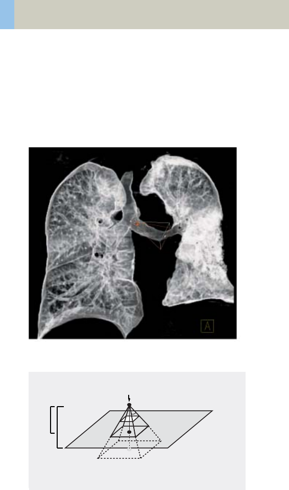
260
syngo Fly Through
Endoscopic Viewing Parameters/Fly Cone Settings
In general, the shape of a pyramidal cone can be used
to represent visualization of an endoscopic volume.
The boundaries and the viewing perspective of the
endoscopic volume are defined by adjusting the shape
and size of this cone.
Cone setting for flying through the airways.
Cone Graphic and Definition
Viewing direction
Image
Plane
Back Clip Plane
Clipping Point
Viewing
Viewing
Standing Point
Viewing
Viewing Angle
Front Clip Plane
Viewing Plane
Depth
Distance
Point
C2-025.630.01.01.02_APPLICATIONGUIDE_SPIRIT.book Page 260 Friday, April 8, 2005 9:55 AM

syngo Fly Through
261
• Standing Point
– The cone rotates around the viewing point.
• Viewing Point
– The complete cone moves.
• Clipping Point
– The cone rotates around the standing point.
• Viewing Angle
– Is changed by moving one of the sides of the
angle.
• Viewing Distance
– The distance from the standing to the viewing
point.
• Viewing Depth
– Moving the Front/Back Clip Plane changes the
viewing depth.
• Front Clip Plane
– To remove foreground-obscuring tissue. The posi-
tion of the front clip plane will always be between
standing and viewing point.
•Back Clip Plane
– To remove tissue at the back of the volume. The
position of the back clip plane will always be
behind viewing point.
C2-025.630.01.01.02_APPLICATIONGUIDE_SPIRIT.book Page 261 Friday, April 8, 2005 9:55 AM

262
syngo Fly Through
Patient Preparation
Bony and cartilaginous structures such as the central
airway and bronchial tree, the osteomeatal system of
the Paranasal Sinuses are inherently filled with air and
therefore ideal for performing Virtual CT Endoscopy.
No special preparations are required.
For CT endoscopic evaluation of the vessel (virtual CT
angioscopy), a good CTA data set with good vessel
enhancement is required.
In the case of CT colonography, adequate preparation
in bowel cleaning must be done prior to the CT exam.
The bowel can be delineated with air, carbon dioxide,
water or iodine/barium suspension.
C2-025.630.01.01.02_APPLICATIONGUIDE_SPIRIT.book Page 262 Friday, April 8, 2005 9:55 AM
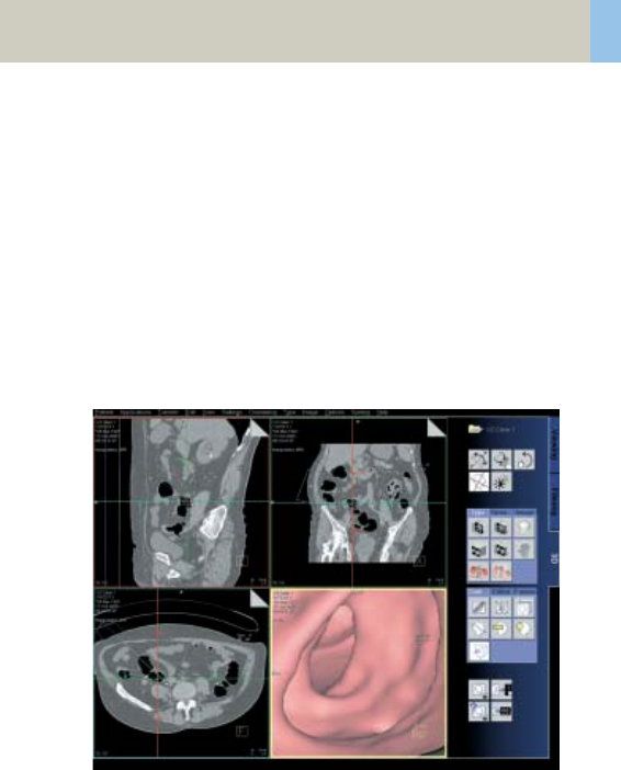
syngo Fly Through
263
Workflow
Load the images in 3D.
The following standard layout is displayed:
Segment 1: Sagittal view
Segment 2: Coronal view
Segment 3: Transversal view
Segment 4: Fly segment with perspective SSD as
default
Scroll through the MPR images until you reach an
image where you would like to start the CT endoscopic
evaluation.
C2-025.630.01.01.02_APPLICATIONGUIDE_SPIRIT.book Page 263 Friday, April 8, 2005 9:55 AM

264
syngo Fly Through
Position the Reference lines at that point of interest e.g.,
in the trachea.
Click the Fly Through icon to activate the endoscopic
display in the fourth segment.
The default endoscopic display has the same orienta-
tion (viewing direction) as the last selected image seg-
ment in which you placed the point of interest and
invoked the syngo Fly Through option.
Change the endoscopic display by adjusting the SSD
threshold or change to VRT display.
Link the new settings to data set for future evaluation.
Define the Cone settings (endoscopic viewing parame-
ters) and link the cone settings to data set for future
application.
Start the endoscopic navigation by using:
• Manual method
• Auto-navigation
• Path creation
Create flight path through the data set and save the
path for future playback.
Click the "Save Image" button before navigating the
endoscopic projection along the path.
A series of endoscopic snapshots will be created and
saved automatically on the database.
These images can be documented on hardcopy or
loaded to Viewer for cine display of the endoscopic
movie.
C2-025.630.01.01.02_APPLICATIONGUIDE_SPIRIT.book Page 264 Friday, April 8, 2005 9:55 AM

syngo Fly Through
265
Navigation of the Endoscopic Volume
•Manual Navigation
Click with the right mouse button in the Fly segment
to activate the SmartSelect menu.
The following controls are available:
– auto-navigation
– push/pull
– rotate around viewing point
–rotate view
Adjust the viewing direction and select push/pull.
Click and hold the left mouse button.
Move the mouse up or down to navigate through the
endoscopic volume manually.
• Auto Navigation
Adjust the initial viewing direction.
Activate the SmartSelect menu
Select the function auto-navigation.
Click and hold with the left mouse button. Give the
mouse a small upward push and then hold it steady.
The software will automatically detect the centerline
and navigate through the endoscopic volume without
any user intervention.
To stop or change the direction of the navigation,
release the mouse and adjust the viewing direction
accordingly before proceeding further.
C2-025.630.01.01.02_APPLICATIONGUIDE_SPIRIT.book Page 265 Friday, April 8, 2005 9:55 AM
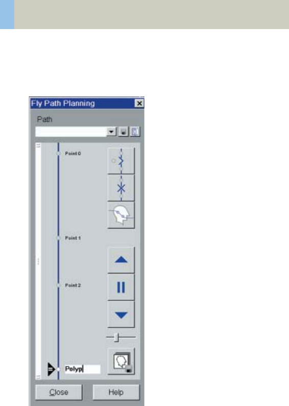
266
syngo Fly Through
Fly Path Planning
Open the Fly Path Planning.
Create a path by inserting path points in the volume
during navigation.
C2-025.630.01.01.02_APPLICATIONGUIDE_SPIRIT.book Page 266 Friday, April 8, 2005 9:55 AM

syngo Fly Through
267
The relevant settings (viewing direction, viewing angle
etc.) are stored along the path.
After defining and storing a path, it is possible to play
back the entire navigation along the path as a movie or
to jump straight to the section of the endoscopic vol-
ume predefined by the path points.
Note: Only one path can be saved with each data set.
To define another flight path through the same vol-
ume, the existing path will be overwritten and deleted.
C2-025.630.01.01.02_APPLICATIONGUIDE_SPIRIT.book Page 267 Friday, April 8, 2005 9:55 AM

268
syngo Dental CT
This is an application package for reformatting pan-
oramic views and paraxial slices through the upper and
lower jaw. It enables the display and measurement of
the bone structures of the upper and lower jaw (espe-
cially for a 1:1 scale) as the basis for oral surgery plan-
ning.
The Basics
What is the relevant anatomical information for oral
surgery planning and dental implantation?
• Location of the socket for dental implant.
• Buccal and lingual thickness of the cortical compo-
nent of the alveolar process.
• Position of the mandibular canal and the mental
foramen.
• Extent of the nasal sinuses and position and width of
the floor of the nasal cavity.
What can syngo Dental CT do?
• Reformatting of a curvilinear range of panoramic
views along the jaw bone.
• Reformatting of paraxial views of selectable length
and at selectable intervals perpendicular to the pan-
oramic views.
• Presentation of results in the form of multiple image
display with reference markings.
• Images are documented on film in "real-size" so that
the direct measurement of the anatomic information
with a ruler is possible. The layout of the film sheet is
predefined such that it can accommodate the maxi-
mum number of reformatted images.
C2-025.630.01.01.02_APPLICATIONGUIDE_SPIRIT.book Page 268 Friday, April 8, 2005 9:55 AM
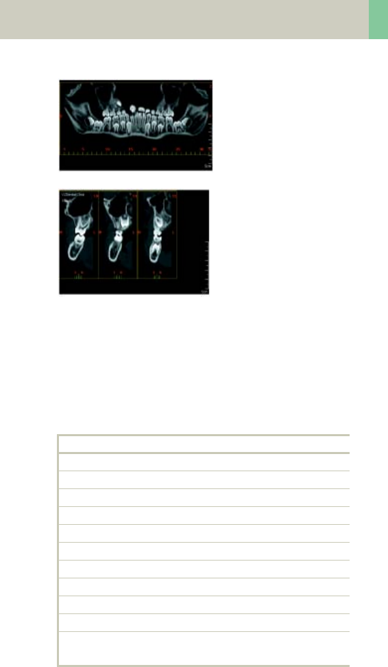
syngo Dental CT
269
Panoramic view
Paraxial view
Scan Protocols
You will find the Dental scan protocols under body
region “Head”:
Dental
kV 130
Effective mAs 45
Rotation time 1.0 sec
Slice collimation 1.0 mm
Slice width 1.25 mm
Feed/Rotation 2.0 mm
Pitch Factor 1.0
Increment 0.5 mm
Kernel H60s
CTDIVol 10.25 mGy
Effective dose Male: 0.13 mSv
Female: 0.16 mSv
C2-025.630.01.01.02_APPLICATIONGUIDE_SPIRIT.book Page 269 Friday, April 8, 2005 9:55 AM
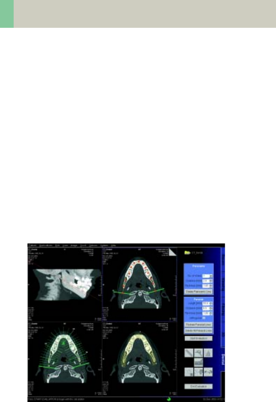
270
syngo Dental CT
• It is mandatory to position the patient head in the
center of the scan field – use the lateral laser light
marker for positioning.
• Gantry tilt is not necessary since you have the ability
to tilt the reference line to generate an axial refor-
matted image at the desired plane. However, in
order to minimize the scan length for the same ana-
tomical region, it is recommended to position the
patient’s head at the appropriate scan plane when-
ever possible:
– For the upper and lower jaw:
occlusal plane in parallel to the scan plane.
– For either jaw:
jaw bone in parallel to the scan plane.
• It is recommended to end the exam first, and then
start the Dental evaluation.
User interface of syngo Dental CT
C2-025.630.01.01.02_APPLICATIONGUIDE_SPIRIT.book Page 270 Friday, April 8, 2005 9:55 AM
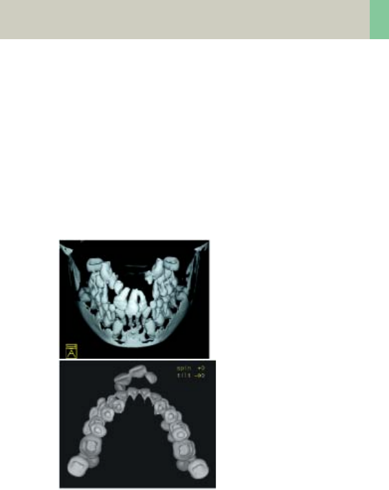
syngo Dental CT
271
Additional Important
Information
• The Dental scan protocol delivers high resolution
images for syngo Dental CT evaluation, however,
you can also reconstruct images with softer kernel,
e.g., H20s, for 3D/SSD post-processing.
TOP-cranial view
Caudal view
C2-025.630.01.01.02_APPLICATIONGUIDE_SPIRIT.book Page 271 Friday, April 8, 2005 9:55 AM

272
syngo Dental CT
• Image orientation:
– In the paraxial view, a “B” indicates buccal and a “L”
lingual. The lingual marker “+” must always be
positioned at the tongue. If not, simply drag &
drop it back.
– In the panoramic view, a “B” stands for “Begin” and
an “E” for “End”.
• Filming: for the maximum use of the film, film
directly from the Dental card instead of Patient
Browser. For easy reprinting, the results of the most
recent syngo Dental CT Film are stored in the Patient
Browser in the folder “Film”.
• It is recommended to change the image windowing
on the virtual film sheet.
• A semi-automatic detection tool can be used to mark
and outline the mandibular canal on both paraxial
and panoramic images for easy viewing and filming.
• Multiple paraxial ranges can be defined on one refer-
ence image by “cluster & copy function”.
I.e., you can group a number of paraxial lines and
copy the lines to another location, e.g., over individ-
ual sockets at different locations.
C2-025.630.01.01.02_APPLICATIONGUIDE_SPIRIT.book Page 272 Friday, April 8, 2005 9:55 AM
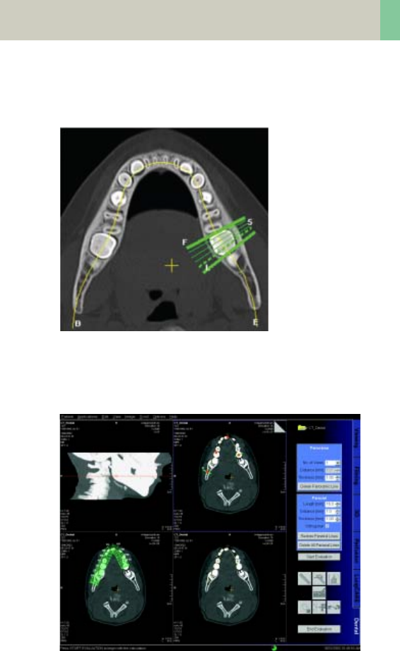
syngo Dental CT
273
• ROI definition for statistical evaluations and deletion
of graphics is possible.
Paraxial
lines using
”Cluster”.
• In the control area, you can configure if you want to
display the paraxial lines orthogonal to the reference
line.
C2-025.630.01.01.02_APPLICATIONGUIDE_SPIRIT.book Page 273 Friday, April 8, 2005 9:55 AM

274
syngo Osteo CT
This is an application package for the quantitative
assessment of vertebral bone mineral density for the
diagnosis and follow-up of osteopenia and osteoporo-
sis.
The Basics
This program enables the quantitative determination
of bone mineral density (BMD) of the spine in mg/ml of
calcium hydroxyapatite (CaHA) to assist the physician
with diagnosis, staging, and follow-up of osteopenia
and osteoporosis with CT. The patient is scanned
together with the water- and bone-equivalent calibra-
tion phantom.
Siemens Reference Data:
The Siemens reference data was acquired at three
European centers, including 135 male and 139 female
subjects, ranging from 20 to 80 years of age.
C2-025.630.01.01.02_APPLICATIONGUIDE_SPIRIT.book Page 274 Friday, April 8, 2005 9:55 AM

syngo Osteo CT
275
Scanning Procedure
Scan Protocols
You will find the Osteo scan protocols under body
region “Spine”:
Osteo
kV 80
Effective mAs 81
Rotation time 1.0 sec
Slice collimation 5.0 mm
Slice width 10.0 mm
Feed/Scan 0.0 mm
Kernel S80s
CTDIVol 2.23 mGy
Effective dose Male: 0.03 mSv
Female: 0.08 mSv
C2-025.630.01.01.02_APPLICATIONGUIDE_SPIRIT.book Page 275 Friday, April 8, 2005 9:55 AM

276
syngo Osteo CT
The special kernels are mostly used for ”physical” mea-
surements with phantoms, e.g., for adjustment proce-
dures (S80s), for constancy and acceptance tests
(S80s, U90s), or for specification purposes (U90s). For
special patient protocols, S80s and U90s are chosen,
e.g., for Osteo (S80s) and for high resolution bone
studies (U90s).
Patient positioning:
• Set the table height at 125. The gantry tilt will be
available from –22° to +22°.
• Patients should be positioned straight on the table.
Support the knees to compensate for lordosis.
• The calibration phantom should be positioned
directly below the target region.
Put the Gel-pad between the calibration phantom
and the patient to exclude air pockets.
Scanning:
• For obese patients increase the mAs value to 120.
• Typically, one scan each is performed at L1, L2 and
L3 levels. Use image comments L1, L2, L3, L4, L5, or
T12 prior to scanning of the respective vertebrae,
these comments will be used for syngo Osteo CT
evaluation results (no blanks or other deviations are
allowed, e.g., use “L4“ instead of “L 4“, or “T12“
instead of “TH12“).
• Before ending the examination, you can drag & drop
the recon jobs from the chronicle to the topogram
segment to get the Topographics, i.e. the cut lines
for each vertebra on the topogram.
C2-025.630.01.01.02_APPLICATIONGUIDE_SPIRIT.book Page 276 Friday, April 8, 2005 9:55 AM
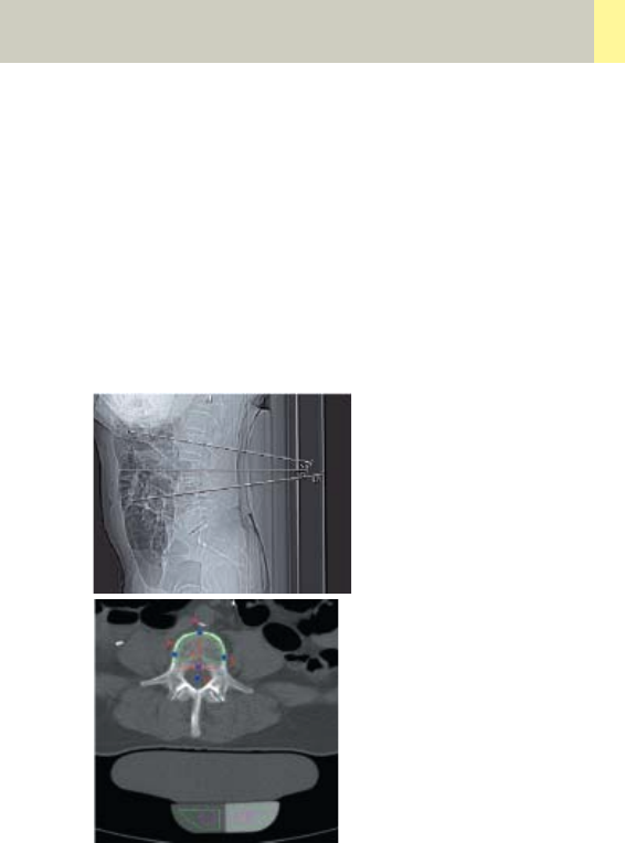
syngo Osteo CT
277
• Position the cut line of scanning through the middle
of the vertebra, i.e. bi-sector between the angle of
the upper and lower end plate.
• The phantom must be included in the FoV of the
images for evaluation.
• It is recommended to end the exam first, and then
start the syngo Osteo CT evaluation.
• Do not use the calibration phantom from other CT
scanners, as your system is calibrated to a particular
phantom.
Topographic
Phantom inside
the FoV
C2-025.630.01.01.02_APPLICATIONGUIDE_SPIRIT.book Page 277 Friday, April 8, 2005 9:55 AM
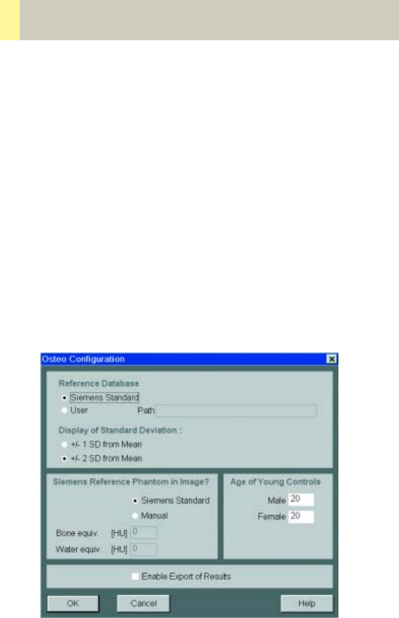
278
syngo Osteo CT
Configuration
In the Osteo configuration you can define the follow-
ing parameters:
You can
• use the Siemens standard reference database or cre-
ate and import your own
• change between 1 and 2 standard deviations (dis-
play of the summary graph)
• use the Siemens Reference phantom or enter values
for bone and water manually
• change the age of the young controls, used for the
calculation of the T-Score
• enable the export of results:
C2-025.630.01.01.02_APPLICATIONGUIDE_SPIRIT.book Page 278 Friday, April 8, 2005 9:55 AM

syngo Osteo CT
279
How can you save the results on your PC?
– Select Option/Configuration from the main menu
and click icon ”CT Osteo”.
– Activate the checkbox “Enable Export of Results”.
– “Exit” the configuration dialog.
– Call up the Osteo card and you will see
the new icon “Export results” on the
lower, right part of the screen.
– Click on this icon to copy the evaluation results to
floppy disk (note: with every mouse click on the icon,
the previous result file will be appended).
– The data file can be transferred to your PC for further
evaluation, e.g., with MS Excel.
C2-025.630.01.01.02_APPLICATIONGUIDE_SPIRIT.book Page 279 Friday, April 8, 2005 9:55 AM

280
syngo Osteo CT
Example for one patient with three Osteo tomo-
grams:
PATIENT; John Smith; 007; 64; Male
IMAGE; L2; 234; 2; 27-JAN-1998; 11:12:17; 61.7;
48.9; 55.3; 20.8; 20.1; 21.5; 205.8; 192.0; 198.7;
50.6; 47.5; 49.5
IMAGE; L3; 236; 3; 27-JAN-1998; 11:12:18; 60.4;
54.5; 49.3; 22.3; 21.1; 21.8; 210.5; 191.9; 180.7;
50.4; 47.5; 52.3
IMAGE; L4; 238; 4; 27-JAN-1998; 11:12:18; 59.3;
43.1; 55.0; 20.6; 29.0; 23.3; 201.8; 178.1; 192.3;
43.6; 45.9; 44.2
REFDATA; 64; Male; 20; -4.35; -3.12; 75.4; 125.3; 26.5
Data structure of the result file:
PATIENT; <Patient name>; <Patient ID>;
<Age of patient>; <Sex of patient>
IMAGE; <Vertebra name>; <Image number>;
<Scan number>; <Scan date>; <Scan time>; <TML>;
<TMR>; <TMT>; <TSL>; <TSR>; <TST>; <CML>; <CMR>;
<CMT>; <CSL>; <CSR>; <CST>
REFDATA; <Age of patient>; <Sex of patient>;
<Age of young normal>; <T-Score>; <Z-Score>;
<BMD reference data, age matched>;
<BMD reference data, young control>;
<Standard deviation reference data>
C2-025.630.01.01.02_APPLICATIONGUIDE_SPIRIT.book Page 280 Friday, April 8, 2005 9:55 AM

syngo Osteo CT
281
Abbreviations:
TML Trabecular Mean Left
TMR Trabecular Mean Right
TMT Trabecular Mean Total
TSL Trabecular Standard Deviation Left
TSR Trabecular Standard Deviation Right
TST Trabecular Standard Deviation Total
CML Cortical Mean Left
CMR Cortical Mean Right
CMT Cortical Mean Total
CSL Cortical Standard Deviation Left
CSR Cortical Standard Deviation Right
CST Cortical Standard Deviation Total
C2-025.630.01.01.02_APPLICATIONGUIDE_SPIRIT.book Page 281 Friday, April 8, 2005 9:55 AM
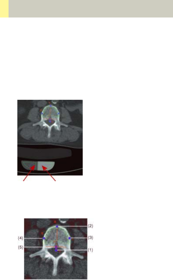
282
syngo Osteo CT
Evaluation Workflow
After loading the images into the syngo Osteo CT appli-
cation, press “Start Evaluation“.
Check the correct positioning of the ROIs in the Calibra-
tion phantom. You can change the position by moving
the two circles.
Correcting contour lines
You can perform correction of the contours by moving
the base points. The following order is recommended:
Water
equivalent
Bone
equivalent
C2-025.630.01.01.02_APPLICATIONGUIDE_SPIRIT.book Page 282 Friday, April 8, 2005 9:55 AM

syngo Osteo CT
283
1.Center of the spinal canal (C)
2.Uppermost point of the cortical spinal body (A)
3.Intermediate point (L)
4.Intermediate point (R)
5.Uppermost point of the spinal canal (T)
– Click on a base point with the mouse.
– Move it keeping the left mouse key pressed.
If you are satisfied with the contours press “Accept
Contours” otherwise skip the image. If the contours for
all images are accepted or skipped, the results are
automatically displayed. The skipped images are not
taken into account.
The third segment contains two summary images:
Displayed results include bone mineral density (mg
CaHA/ml) and standard deviation. The results are listed
in a table:
• the evaluated vertebra
(if the comment is correctly inserted, e.g., L1)
• the scan number of the image
• the trabecular bone mineral density for each verte-
bra and the pixel standard deviation (in brackets)
• the cortical bone mineral density for each vertebra
and the pixel standard deviation (in brackets)
• additionally, the average and standard deviation
over all evaluated vertebrae are listed
C2-025.630.01.01.02_APPLICATIONGUIDE_SPIRIT.book Page 283 Friday, April 8, 2005 9:55 AM
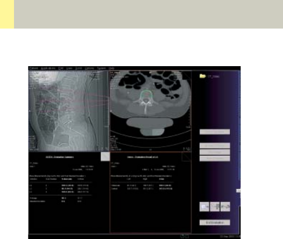
284
syngo Osteo CT
The other summary image displays a graph which
shows the comparison of all evaluated vertebrae with
the selected Reference Data.
“T-score”
This is the deviation of average BMD of the patient
from that of a young healthy comparison group. It rep-
resents bone loss with reference to the peak bone
mass.
“Z-score”
This is the deviation of average BMD of the patient
from that of a healthy person of the same age. It is an
indicator of biological variability.
C2-025.630.01.01.02_APPLICATIONGUIDE_SPIRIT.book Page 284 Friday, April 8, 2005 9:55 AM
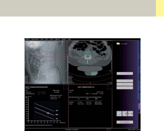
syngo Osteo CT
285
The second and the fourth segment belong together.
The second segment shows the tomogram images
with the contours superimposed. The fourth segment
shows the calculated results of the corresponding
tomogram image. Both segments are bordered by the
same color. If you scroll through one of these seg-
ments the other segment is updated to same vertebra.
C2-025.630.01.01.02_APPLICATIONGUIDE_SPIRIT.book Page 285 Friday, April 8, 2005 9:55 AM
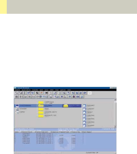
286
syngo Osteo CT
After “End Evaluation“ the evaluation results are auto-
matically saved in three series:
– Summary
contains both images of the third segment
–Contours
contains the tomogram images with the contours
superimposed (second segment)
–Tables
contains the result tables for each vertebra (fourth
segment)
C2-025.630.01.01.02_APPLICATIONGUIDE_SPIRIT.book Page 286 Friday, April 8, 2005 9:55 AM
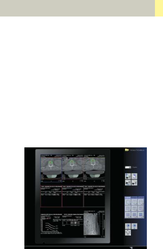
syngo Osteo CT
287
Additional Important
Information
• Fractured vertebrae are not suited for syngo Osteo
CT evaluation since the more compact nature of
these vertebrae result in bone mineral density value
that is much higher than one would expect.
• When you examine a patient who is older than 80
years, the patient examination data cannot be com-
pared with the reference data base.
• It is recommended to film directly from the Osteo
card. Select images or series with Edit/Select all, and
click “film” icon. You can also configure your film lay-
out, e.g., 3 x 3 as shown in Option/Configuration/
FilmingLayout.
Filming layout
Note: it is not recommended to use filming layout set-
ting of 4 x 5 segments since the image text elements
of the result image are overlapped and hard to read.
C2-025.630.01.01.02_APPLICATIONGUIDE_SPIRIT.book Page 287 Friday, April 8, 2005 9:55 AM

288
syngo Volume Evaluation
Volume is an evaluation function which allows most
accurate calculation of a volume out of a stack of two-
dimensional images.
This can be done by Volume-of-Interest (VOI) defini-
tion and by limiting the minimum and maximum den-
sity (HU) values for calculation. Different views of the
image data provide fast navigation and easy volume
definition.
Potential applications are volume measurements of a
tumor or organs such as lung and kidney.
To do this, the Volume Evaluation card provides you
with the following features:
• Evaluation on a separate syngo card on the user
interface.
• Calculation of 5 different Volumes is possible in par-
allel.
• For easy navigation, the image data is displayed in 3
different views: coronal, sagittal and transversal.
•Use of syngo functions such as Navigation lines and
dog-ears can be used for fast paging through each
view.
• Transversal thick slice Multi Planar Reformat (MPR),
Maximum Intensity Projection (MIP) or Minimum
Intensity Projection (MinIP) segments are available
for better recognition of the Volume of Interest.
• Zoom & Pan is available for each image segment
which is especially helpful for Volume definition of
smaller structures.
C2-025.630.01.01.02_APPLICATIONGUIDE_SPIRIT.book Page 288 Friday, April 8, 2005 9:55 AM

syngo Volume Evaluation
289
• Interactive outlining of freehand and elliptical
Regions-of-Interest is available, with the possibility
to define evaluation (HU) limits inside the VOI.
• Automatic interpolation between two pending ROIs
is performed, i.e. the user only has to define the ROI
in selected images within the stack.
• Automatic detection of a volume using threshold
based 3D region growing, for quick calculation of
high contrast structures such as bone, lung or con-
trast filled organs.
• Combination of interactive and automatic approach
possible.
• Dedicated linking methods available for fusion or
separation of ROIs, in order to define complex vol-
umes.
• Display of color-coded VOIs for easy differentiation
of multiple volumes.
• Configuration of result parameters.
C2-025.630.01.01.02_APPLICATIONGUIDE_SPIRIT.book Page 289 Friday, April 8, 2005 9:55 AM

290
syngo Volume Evaluation
Prerequisites
The images must fulfill the following conditions:
• Only images of one patient must be loaded for eval-
uation with Volume.
• The scans must have been acquired with the same
table height and the same gantry tilt.
• Only image data sets with the same slice orientation
must be used; (the selection should not include a
topogram image).
• The loaded images must have the same zoom factor
and the same reconstruction center.
• At least four images must be loaded before volume
evaluation can be performed.
• The time range between the first and the last image
must not exceed one hour.
• The data capacity of the volume must not exceed
1024 images with matrix dimensions of
512 x 512 pixels.
C2-025.630.01.01.02_APPLICATIONGUIDE_SPIRIT.book Page 290 Friday, April 8, 2005 9:55 AM
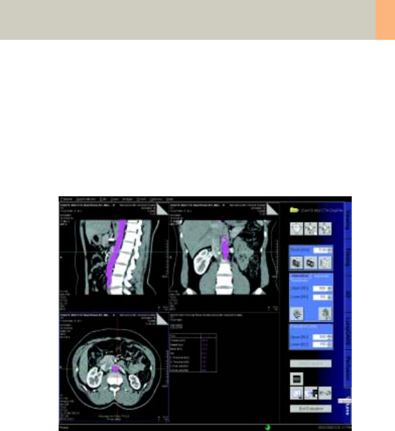
syngo Volume Evaluation
291
Workflow
1. Loading the Images
After loading the images into syngo Volume Evalua-
tion, the following layout is displayed:
• Segment 1: Display of sagittal images.
The images are sorted from left to right, according to
the patient’s anatomy.
• Segment 2: Display of coronal images.
The images are sorted from front to back, according
to the patient’s anatomy.
• Segment 3: Display of transversal images.
The images are sorted from head to feet, according
to the patient’s anatomy.
• Segment 4: Display of either the evaluation results or
thick slice images (MaxIP, MinIP or MPR images) that
correspond to the transversal images in segment 3.
C2-025.630.01.01.02_APPLICATIONGUIDE_SPIRIT.book Page 291 Friday, April 8, 2005 9:55 AM

292
syngo Volume Evaluation
2.Preparing Volume Calculation
Before you start the volume definition, first optimize
the display of the images. To make interactive volume
definition easier, you can
• delete images that you do not require for volume cal-
culation from the original data set
• change the display of the images in the MIP/results
segment using the display mode (MaxIP, MinIP or
MPR) and the slice thickness
• scroll through the image stack
• window, zoom and pan images
• show/hide image text display
• set evaluation limits: Using the evaluation limits you
can perform volume calculation within a defined HU
value range
3. Planning a Volume
Volume Evaluation offers different tools and methods
to plan a volume.
• You can use the Automatic Volume Detection fea-
ture, where the system automatically defines a vol-
ume around a seed point. Volume CT searches for
directly connected voxels within a defined HU range
and assigns them to the volume.
• You can use the Interactive Volume Definition,
where you draw either elliptical or freehand regions
of interest (ROIs) on the images. The ROI contours
define the outer border of the volume.
C2-025.630.01.01.02_APPLICATIONGUIDE_SPIRIT.book Page 292 Friday, April 8, 2005 9:55 AM

syngo Volume Evaluation
293
3.1. Planning a Volume with Automatic Volume Detec-
tion
The automatic method is best used to evaluate a struc-
ture which has a different contrast (HU) than the sur-
rounding tissue, such as the lung. You plan the volume
with just a few clicks.
Automatic Volume Detection uses the 3D region grow-
ing method. You enter thresholds that are to be consid-
ered for region growing and set seed points.
Volume Evaluation searches for directly connected
voxels within the threshold limits, and assigns them to
the VOI.
The system then generates a volume considering all
voxels that are found with region growing and which
CT value lies within the Evaluation Limits.
• Check and adapt the Thresholds, if necessary.
• Set a seed point.
• To enlarge the volume, set additional seed points.
• To only include a specific range of HU values into the
volume, change the Evaluation Limits. By default,
the Evaluation Limits are identical to the Threshold.
• To start the evaluation, click the Start Evaluation but-
ton. The evaluation results are displayed in segment
4. The volume is colored on all images in all views.
• You can define a new volume.
You can correct the Evaluation Limits and restart the
evaluation. If the result is not satisfactory, you can
delete the volume.
C2-025.630.01.01.02_APPLICATIONGUIDE_SPIRIT.book Page 293 Friday, April 8, 2005 9:55 AM

294
syngo Volume Evaluation
Restricting Automatic Volume Detection
You can restrict Automatic Volume Detection to a
defined smaller volume.
• Draw an ROI around the image area of interest on at
least the first and the last image that you want to be
included in the volume. The ROIs define the bound-
ing box for the automatic approach.
• Check the Thresholds and set the seed point inside
the object to be detected.
• Region growing only includes voxels that fulfill the
following conditions:
– Their HU value lies within the thresholds.
– They are connected to the seed point.
– They lie inside the bounding box.
3.2 Planning a Volume with the Interactive Volume
Definition
For structures that are not so well defined, it is recom-
mended to use the Interactive Volume Definition
method. You can precisely adapt the ROIs to complex
body structures.
You can draw either elliptical or freehand ROIs on the
transversal images or on the thick slice images (for fast
navigation).
C2-025.630.01.01.02_APPLICATIONGUIDE_SPIRIT.book Page 294 Friday, April 8, 2005 9:55 AM

syngo Volume Evaluation
295
The contours of the ROIs define the outer border of the
evaluated volume. You do not need to define the ROIs
on every slice. The system automatically interpolates
ROIs on the images which lie between the images with
defined ROIs.
• Check the images and search for the desired object
structure.
• You can start on any image in segments 3 or 4.
We recommend displaying an image that shows the
center of the desired structure.
• Draw an ROI around the area that is to be considered
to be part of the object structure.
• Do the same on another image, for example, the first
or last image that shows the structure.
The system automatically inserts ROIs on the inter-
mediate images. These ROIs are drawn with a dotted
line to indicate that they are assumed for the evalua-
tion of the volume, but that they are not confirmed
by you. The contour of a user-defined ROI is a solid
line. All ROIs have the same color and number.
• Scroll through the images and modify, if necessary,
the interpolated ROIs to the true structure of the
desired volume. You can edit an interpolated ROI or
replace it with a new ROI.
• To extend the volume, insert an ROI before/after the
first/last image on which an ROI is already defined.
C2-025.630.01.01.02_APPLICATIONGUIDE_SPIRIT.book Page 295 Friday, April 8, 2005 9:55 AM

296
syngo Volume Evaluation
• To include only a specific range of HU values into the
volume, change the Evaluation Limits.
By default, the Evaluation Limits take all HU values of
the last evaluation.
• To start the evaluation, click the Start Evaluation but-
ton. The evaluation results are displayed in
segment 4. The volume is colored on all images in all
views.
• You can define a new volume.
You can correct the Evaluation Limits and restart the
evaluation. If the result is not satisfactory, you can
delete the volume.
C2-025.630.01.01.02_APPLICATIONGUIDE_SPIRIT.book Page 296 Friday, April 8, 2005 9:55 AM
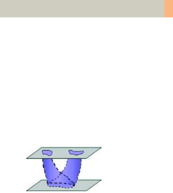
syngo Volume Evaluation
297
Overlap and Mark&Link Method
You can define complex volumes using the automatic
(overlap) and manual (mark&link) method.
• Overlapping method
Drawn ROIs that overlap each other vertically for at
least a few pixels are automatically combined to one
volume. Interpolated ROIs (dotted line) are shown in
the intermediate images.
Two or more small ROIs that are drawn within one
image and a big ROI in a different image that overlaps
both small ROIs are automatically combined into one
volume. This works in both directions:
top-down and bottom-up.
C2-025.630.01.01.02_APPLICATIONGUIDE_SPIRIT.book Page 297 Friday, April 8, 2005 9:55 AM
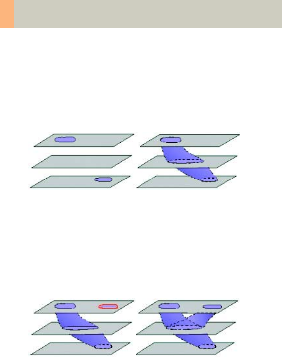
298
syngo Volume Evaluation
With the Overlap method, you can also create a vol-
ume from two ROIs that do not overlap in the first step.
It is then necessary to draw an ROI in an image which
lies between the two other ROIs, so that the new ROI
overlaps with the two previous ROIs. This way, you can
easily define a VOI around tortuous body structures.
• Mark & link method
If two ROIs do not have a common projection point,
you can link them manually for interpolation.
You can link non-overlapping ROIs to one volume. First
you mark one ROI, and then you link a second ROI to it.
The system connects the ROIs and inserts interpolated
ROIs on the intermediate images.
C2-025.630.01.01.02_APPLICATIONGUIDE_SPIRIT.book Page 298 Friday, April 8, 2005 9:55 AM

syngo Volume Evaluation
299
4. Evaluation Results
When you click the Start Evaluation button, the system
calculates the planned volume within the evaluation
limits.
The evaluation results are displayed in segment 4. Only
the statistic parameters that are set in the configura-
tion dialog box are calculated. Volume pixels and eval-
uation results are the same color.
The evaluation results and the thick slice images are
both displayed in segment 4. To switch the display,
click the MIP/Result icon.
The evaluation results include general patient informa-
tion, date and time of the evaluation and for each vol-
ume the configured statistic parameters.
•Volume [cm3/mm3] Size of the volume.
•Height [cm/mm] Maximum height of the volume in
cm – corresponding to the patient’s anatomical feet-
to-head orientation.
•Width [cm/mm] Maximum width of the volume in
cm – corresponding to the patient’s anatomical left-
to-right orientation.
•Depth [cm/mm] Maximum depth of the volume in
cm – corresponding to the patient’s anatomical ante-
rior to posterior orientation.
•Mean [HU] Mean CT value of the volume in HU.
•SD Standard deviation from the Mean value [HU].
•L Threshold [HU] Lower threshold considered for
automatic volume detection.
•U Threshold [HU] Upper threshold considered for
automatic volume detection.
•L Eval Limit [HU] Lower evaluation limit considered
for volume calculation.
•U Eval Limit [HU] Upper evaluation limit considered
for volume calculation.
C2-025.630.01.01.02_APPLICATIONGUIDE_SPIRIT.book Page 299 Friday, April 8, 2005 9:55 AM

300
syngo Volume Evaluation
5. Documentation of Results
If all volumes are evaluated, you can save and film the
results.
Save – stores to your local database:
• The transversal images with the color-coded VOI
• The reformatted images (sagittal, coronal, MPR/MIP)
• The displayed result sheet
Two new series are created.
• The “VolumeResult“ series, which consists of the 4
images and the result sheet that are currently dis-
played.
• The “VolumeAxial“ series, which is a copy of the
loaded transversal images and also includes the
color-coded ROIs.
General Hints
•Loading Images
After all images are loaded, your system checks
whether the sorted images have an equally spaced
ascending or descending timestamp. If that is not the
case, a warning box is displayed but loading is contin-
ued.
If the distance between slices and the slice thickness of
the loaded images are not identical, a warning box is
also displayed.
C2-025.630.01.01.02_APPLICATIONGUIDE_SPIRIT.book Page 300 Friday, April 8, 2005 9:55 AM

syngo Volume Evaluation
301
•ROI and Volume Definition
– If you insert/modify an ROI, the system automati-
cally plans the ROIs on the preceding/following
images (interpolated ROIs) up to that image with
the previous/next user-defined ROI.
– User-defined ROIs have a solid contour line,
whereas interpolated ROIs have a dotted contour
line.
– When you modify an interpolated ROI (dotted
line), it becomes an user-confirmed ROI and is dis-
played with a solid line.
– The system never modifies the shape of a user-
defined ROI. In case that you insert or modify an
ROI, the shape of previous/following interpolated
ROIs may change.
– If a new ROI touches or overlaps another user-
defined ROI (solid line), the ROIs are merged dur-
ing volume calculation.
– If a new ROI touches or overlaps an interpolated
ROI (dotted line), the new ROI replaces the system
defined ROI.
C2-025.630.01.01.02_APPLICATIONGUIDE_SPIRIT.book Page 301 Friday, April 8, 2005 9:55 AM

302
syngo Volume Evaluation
•Restrictions for Linking and Unlinking
There are some restrictions for linking and unlinking:
– Linking can be done on user-defined ROIs as well
as on interpolated ROIs. If you link an interpolated
ROI (dotted line), it becomes a user-confirmed ROI
(solid line).
– You cannot unlink interpolated ROIs. The unlinking
only works with user-confirmed ROIs.
– If you modify the volume (for example, move a
ROI) before linking an ROI to the already selected
ROI, the marking is reset.
• Evaluation
– Bounding voxels, where no voxel lies within the
entered range of HU values, stops region growing.
Check the depth of the volume in the coronal and
sagittal view. To complete region growing inside the
entire volume, set multiple seed points if necessary.
– You can edit the thresholds even after the volume
has been evaluated.
– You can modify or delete the last evaluated volume.
C2-025.630.01.01.02_APPLICATIONGUIDE_SPIRIT.book Page 302 Friday, April 8, 2005 9:55 AM
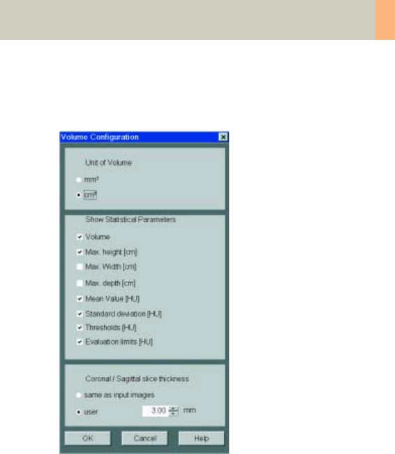
syngo Volume Evaluation
303
Configuration
In the Volume Configuration dialog box, you define
which evaluation results are given by Volume Evalua-
tion.
– Unit of Volume
mm3 Volume is given in mm3.
cm3 Volume is given in cm3.
C2-025.630.01.01.02_APPLICATIONGUIDE_SPIRIT.book Page 303 Friday, April 8, 2005 9:55 AM

304
syngo Volume Evaluation
– Statistical Parameters
Volume Volume is calculated in the defined unit:
mm3 or cm3.
Max. height [cm] Maximum height of the recon-
structed volume.
Max. width [cm] Maximum width of the recon-
structed volume.
Max. depth [cm] Maximum depth of the recon-
structed volume.
Mean value [HU] Mean CT value of the volume in
HU.
Standard deviation [HU] Pixel standard deviation.
Thresholds [HU] Range of CT values that have been
considered for automatic volume detection in HU.
Evaluation limits [HU] Range of CT values that have
been considered for volume calculation in HU.
– Coronal/Sagittal slice thickness
In the Coronal/Sagittal slice thickness area you can
preset the slice thickness for sagittal and coronal
images.
Select same as input images if you want to have the
slice thickness of the input images applied.
C2-025.630.01.01.02_APPLICATIONGUIDE_SPIRIT.book Page 304 Friday, April 8, 2005 9:55 AM

syngo Volume Evaluation
305
C2-025.630.01.01.02_APPLICATIONGUIDE_SPIRIT.book Page 305 Friday, April 8, 2005 9:55 AM

306
Dynamic evaluation is a function which allows you to
analyze the absolute or relative enhancement of Houn-
sfield values within a Region of Interest.
The enhancement value is computed from a stack of
CT images which are obtained at different points in
time after contrast agent injection. For dynamic evalu-
ation, usually images from the same cross-section of
the body are taken, such as a Multi-scan through an
unclear process in the liver.
The time to the maximum enhancement (Time-to-
Peak) and the way a certain tissue or structure absorbs
the contrast medium can be very helpful in differential
diagnosis of a given process.
To do this, the Dynamic Evaluation card provides you
with the following methods:
• Evaluation on a separate syngo card on the user
interface.
• Selection dialog for slice positions to be evaluated in
Multi-slice studies.
• Volume data sets can be evaluated also, e.g., for
measurement of contrast enhancement in a vessel
during spiral acquisition and further optimization of
contrast injection procedure for follow-up studies.
• Dynamic evaluation of 5 different regions (circular
and irregular) and a pixel lens are possible in parallel.
• ROI definition and pixel lens are automatically cop-
ied to all pending images of the stack and show an
immediate display of the time-density curves, i.e. a
calculation can be done with only one interaction.
syngo Dynamic Evaluation
C2-025.630.01.01.02_APPLICATIONGUIDE_SPIRIT.book Page 306 Friday, April 8, 2005 9:55 AM

syngo Dynamic Evaluation
307
•Use of syngo functions like dog-ears or cine mode for
fast paging through the image stack.
• Easy selection, modification and deletion handling
for the ROIs.
• Constant display of the time-density curves with a
scalable sampling line, and of the tabular results
which display for each separate ROI
– the mean Hounsfield value
– the time to the peak enhancement (in seconds)
– the density value (HU) of a given time position,
chosen by shifting the sampling line to that point.
• Separate image stack segment for further output
images such as
– Average image
– Maximum Intensity Projection image
– Peak Enhancement image
– Time-to-Peak image.
• Configuration dialog to enable customized results.
C2-025.630.01.01.02_APPLICATIONGUIDE_SPIRIT.book Page 307 Friday, April 8, 2005 9:55 AM

308
syngo Dynamic Evaluation
Prerequisites
In dynamic evaluation, images that were scanned as
part of an examination with contrast agent at a con-
stant table position are evaluated.
• The selection consists only of CT tomogram images.
• The images belong to the same study.
• The images were acquired within 1 hour.
• Images of at least 4 different time positions must be
loaded to Dynamic Evaluation.
• The relevant DICOM attributes are the same on all
images.
C2-025.630.01.01.02_APPLICATIONGUIDE_SPIRIT.book Page 308 Friday, April 8, 2005 9:55 AM
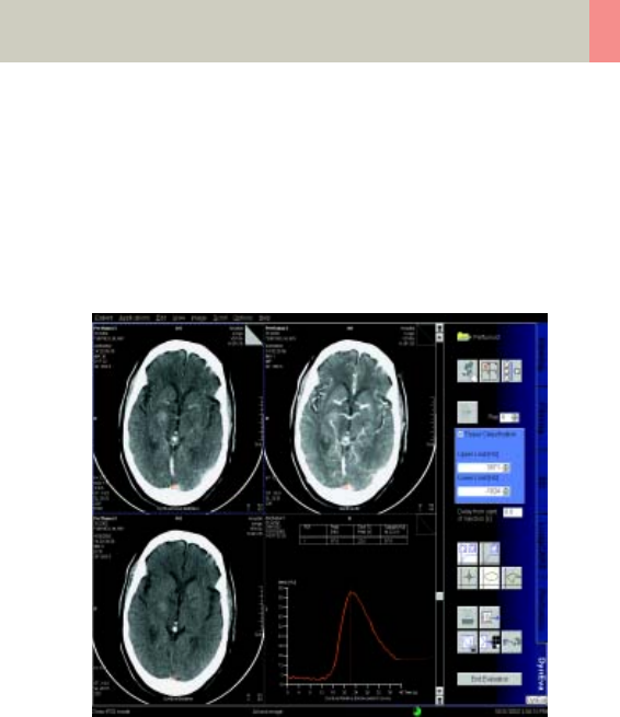
syngo Dynamic Evaluation
309
Workflow
1. Loading the Images
After loading the images into syngo Dynamic Evalua-
tion, the following layout is displayed:
• Tomo segment
The loaded input images are displayed in the upper
left-hand segment. The images are sorted by the
acquired time.
• Parameter image segment
Parameter images are displayed in the upper right-
hand segment
– MIP image
– Average image
– Peak Enhancement image/Time to Peak image
C2-025.630.01.01.02_APPLICATIONGUIDE_SPIRIT.book Page 309 Friday, April 8, 2005 9:55 AM

310
syngo Dynamic Evaluation
• Baseline image segment
The baseline image is displayed in the lower left
hand segment (base for enhancement calculation).
By default, the first image of the loaded images is
used as the baseline image.
• Result segment
It is black after loading.
2. Inspecting the Input Images
Before you begin the evaluation, optimize the display
of loaded images in the tomo segment in such away
that the regions to be evaluated are clearly visible:
– Scroll through the image stack
– Window, zoom and pan images
– Remove the images that are not suitable for dynamic
evaluation (e.g., when the patient has moved during
scanning).
3. Generation of Parameter Images
As soon as you load the original image material, your
system performs an evaluation of the entire image
area. The results (parameter images) are displayed in
the parameter image segment.
C2-025.630.01.01.02_APPLICATIONGUIDE_SPIRIT.book Page 310 Friday, April 8, 2005 9:55 AM

syngo Dynamic Evaluation
311
Each time you make a change to the original data set
(by removing images, and/or defining a new baseline
image) your system recalculates the parameter images
based on the existing images.
–The average image is an averaged addition of all
pixels at each pixel location across the images of the
tomo segment.
–MIP image: Parameter image where each pixel is the
maximum value of all images at that pixel location.
The image data is checked pixel by pixel. The pixels
with the maximum intensity are displayed in an
image.
–Time to Peak image: Parameter image where each
pixel indicates the period of time (in tenths of a sec-
ond) from the time when the first image was
acquired (Delay = 0) or the time when the contrast
was injected (Delay > 0) to the time when the high-
est CT value is reached at that pixel location. The
longer the time period until the peak CT value is
reached, the brighter the pixels.
With a Time to Peak image, for example, you can easily
detect structures in which the contrast did not spread
as fast as in comparable structures.
Hint: The time to peak (in seconds) at the cursor posi-
tion in the Time to Peak image is the CT value displayed
in the lower right corner divided by 10.
C2-025.630.01.01.02_APPLICATIONGUIDE_SPIRIT.book Page 311 Friday, April 8, 2005 9:55 AM

312
syngo Dynamic Evaluation
–Peak Enhancement image: Parameter image where
each pixel indicates the enhancement at that pixel
location.
CT value of a pixel = maximum value found at that
pixel location (pixel value of the MIP image) – CT
value of the baseline image at that pixel location.
With a Peak Enhancement image, for example, you
can easily detect structures that were not completely
filled with contrast.
Hint: You can activate or deactivate the calculation of
the Time to Peak image and the Peak Enhancement
image in the configuration.
C2-025.630.01.01.02_APPLICATIONGUIDE_SPIRIT.book Page 312 Friday, April 8, 2005 9:55 AM

syngo Dynamic Evaluation
313
4. Creating a Baseline Image
A baseline image is used as a basis for all enhancement
calculations.
The enhancement is calculated relatively to the base-
line image. Therefore, the baseline image must show
the state before enhancement starts.
By default, the first image of the loaded images is used
as the baseline image.
Before the enhancement starts, you can also define
the last image as the baseline image. If you do so, the
mean gray values of the selected image and all the
images that have been acquired before the selected
image are displayed in the baseline image. The result is
a smoother image that can be used to define the ROIs.
If you want to use a different baseline image, proceed
as follows:
• Scroll to the required image in the tomo segment.
• Click on the button Generate baseline image with
the mouse.
C2-025.630.01.01.02_APPLICATIONGUIDE_SPIRIT.book Page 313 Friday, April 8, 2005 9:55 AM
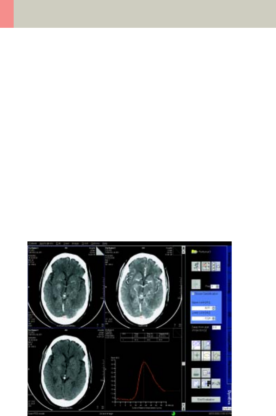
314
syngo Dynamic Evaluation
5. Evaluation of Region of Interests
You select the image regions to be evaluated by mark-
ing them with ROIs or applying the pixel lens (a circular
ROI with a fixed but configurable diameter). An abso-
lute/relative CT-value calculation is performed for
these selected image.
• You can draw either elliptical or freehand ROIs.
• You can modify an ROI in any image, precisely adapt-
ing it to the shape you feel is relevant.
• The number of ROIs that can be defined is limited to
five – you can only draw one pixel lens.
• The ROIs that you have drawn are transferred to the
other views.
• To aid examination, they are numbered in sequence
and color-coded.
Display of the Pixel Lens curve
C2-025.630.01.01.02_APPLICATIONGUIDE_SPIRIT.book Page 314 Friday, April 8, 2005 9:55 AM

syngo Dynamic Evaluation
315
6. Enhancement Curve
As soon as you have defined an ROI, an enhancement
curve (time-density curve) is calculated and displayed
in the fourth segment. To facilitate identification, this
curve has the same color and numbering as the associ-
ated ROI. The maximum CT-value of the ROI first drawn
is indicated by a dashed sampling line.
In the table, for each ROI, the following parameters are
given:
• Peak [HU]: Highest CT value detected in the ROI.
• Time to Peak [s]: Period of time in seconds from the
time when the first image was acquired (Delay = 0)
or the time when the contrast was injected
(Delay > 0) to the time when the highest CT value is
reached in an ROI.
• Sample [HU]: CT value at the point of time (in sec)
where the vertical line is positioned on the enhance-
ment curve.
Absolute/Relative Enhancement curve
The enhancement curves are displayed as absolute or
relative curves.
• The Absolute Enhancement curve displays the origi-
nal CT-value derived at every point in time during the
examination.
• The Relative Enhancement curve displays the varia-
tion of CT-values with reference to the CT-values in
the baseline image at every point in time.
C2-025.630.01.01.02_APPLICATIONGUIDE_SPIRIT.book Page 315 Friday, April 8, 2005 9:55 AM

316
syngo Dynamic Evaluation
7. Documentation of Results
During the evaluation you have drawn individual ROIs
and have generated enhancement curves and result
tables. You can save and print out this information or
store it on a floppy for further processing.
To document the evaluation, two new series are stored
to your local database.
•The “DynEva Curves“ series consists of 3 images and
the result sheet that is currently displayed:
– One original or (fused) Multi-slice image currently
displayed.
– The image displayed in segment 2, for example,
the MIP image.
– The baseline image.
– The displayed result sheet.
•The “DynEva Parameter“ series consists of the
parameter images in segment 2:
– The Time to Peak image (if configured).
– The Peak Enhancement image (if configured).
– The Average image.
–The MIP image.
C2-025.630.01.01.02_APPLICATIONGUIDE_SPIRIT.book Page 316 Friday, April 8, 2005 9:55 AM

syngo Dynamic Evaluation
317
General Hints
•Slice Position with Multi-Row Scanners
When you use a multi-row scanner, several slice posi-
tions are scanned per acquisition. When you load the
images, the window Slice Selection is displayed, in
which you can define the slice position to be analyzed.
You can evaluate either the scanned examination data
or an averaged slice position.
•Help to Interpret the Enhancement
Parameter images that help to interpret the enhance-
ment are displayed in segment 2, for example, the MIP
image and the Peak Enhancement image.
•Defining the Tissue Range
With Tissue Classification you can exclude all tissue
regions outside the CT-value range entered. This
allows you to emphasize the organ to be examined and
remove disturbing factors.
HU limitation does not affect evaluation of the ROIs
and only appears at the Time to Peak and the Peak
Enhancement image.
The excluded tissue densities are masked by a color in
the baseline image. The excluded areas are displayed
in black in the Time to Peak and Peak Enhancement
images.
C2-025.630.01.01.02_APPLICATIONGUIDE_SPIRIT.book Page 317 Friday, April 8, 2005 9:55 AM

318
syngo Dynamic Evaluation
•Filtering
To reduce noise in the Time to Peak and Peak Enhance-
ment image you can apply a smoothing filter.
Filtering does not affect the evaluation of ROIs.
•Moving the Sampling Line
If you want to evaluate the enhancement values for a
different point in time, move the sampling line in the
horizontal direction.
You can display the tomographic image for the time
marked by the sampling line as the top image in the
tomo segment. To do that, double-click on the sam-
pling line.
•Delay of Injection
You usually start the CT scans with contrast medium
after a delay following contrast medium injection. You
can have this off-set taken into account in calculation
of the Time to Peak image and enhancement curves.
The results then refer to the time of contrast medium
administration (zero on the time scale).
➭Enter the delay from the start of injection of the con-
trast to the start of the scan and confirm with the
Enter key.
C2-025.630.01.01.02_APPLICATIONGUIDE_SPIRIT.book Page 318 Friday, April 8, 2005 9:55 AM

syngo Dynamic Evaluation
319
•Relative Enhancement Curve
Time Axis (X)
The point of time for an image is computed relative to
the point of time at which the first input image was
acquired:
Point of Time = Acquisition Time – Acquisition Time of
the First Image + Delay
•Enhancement Axis (Y)
The mean CT value of each ROI is plotted on the
enhancement axis of the enhancement curve.
The value is relative to the CT values of the baseline
image. The mean CT value of an ROI inside the baseline
image is assumed to be “0“.
•Absolute Enhancement Curve
Enhancement Axis (Y)
The point of time for an image is computed relative to
the point of time at which the first input image was
acquired:
Point of Time = Acquisition Time – Acquisition Time of
the First Image + Delay
Enhancement Axis (Y)
The absolute mean CT value of each ROI is plotted on
the enhancement axis of the enhancement curve.
C2-025.630.01.01.02_APPLICATIONGUIDE_SPIRIT.book Page 319 Friday, April 8, 2005 9:55 AM
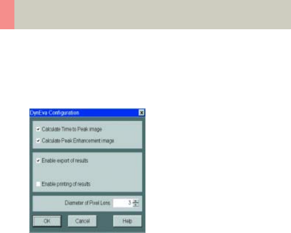
320
syngo Dynamic Evaluation
•Configuring Dynamic Evaluation
You can make the following settings in DynEva Config-
uration:
–Calculate Time to Peak Image
A Time to Peak Image is generated and displayed in
the upper right-hand segment. You can use the
image for ROI definition.
–Calculate Peak Enhancement Image
A Peak Enhancement Image is generated and dis-
played in the upper right-hand segment. You can use
the image for ROI definition.
–Enable export of results
Enables the export feature: Results can be stored on
floppy disk.
–Enable printing of results
Enables the print feature: Results can be printed.
–Diameter of Pixel Lens
Diameter of the circular ROI (pixel lens) in pixels.
C2-025.630.01.01.02_APPLICATIONGUIDE_SPIRIT.book Page 320 Friday, April 8, 2005 9:55 AM

Authorized Representative
according to the Medical
Device Directive 93/42/EEC
Siemens AG
Medical Solutions
Henkestr. 127
D-91052 Erlangen
Germany
Telephone: +49 9131 84-0
www.siemens.com/medical
Manufacturer
Siemens Shanghai Medical
Equipment Ltd. (SSME)
278 Jin Hu Road
201206 Shanghai, P.R. China
Telephone: +86 21 50320300
© 2002-2005, Siemens Shanghai
Medical Equipment Ltd. (SSME)
Order No.
C2-025.630.01.01.02
Printed in China
02/2005
C2-025.630.01.01.02_APPLICATIONGUIDE_SPIRIT.book Page 321 Friday, April 8, 2005 9:55 AM
