Siemens Wireless Office Headset Simatics Pcs7 Users Manual SIMATIC PCS 7 TeleControl Process Control System With Integral Technology
SIMATICS PCS7 to the manual 674e6492-5fc1-421a-8555-6d0a048c8112
2015-02-05
: Siemens Siemens-Wireless-Office-Headset-Simatics-Pcs7-Users-Manual-410675 siemens-wireless-office-headset-simatics-pcs7-users-manual-410675 siemens pdf
Open the PDF directly: View PDF ![]() .
.
Page Count: 32
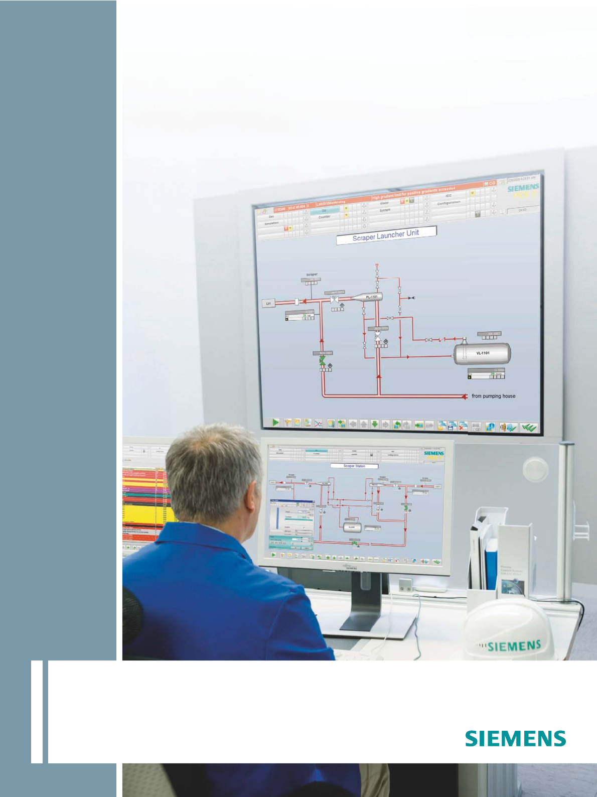
SIMATIC PCS 7 TeleControl
Process control system with
integral telecontrol technology
Brochure · January 2011
SIMATIC PCS 7
Answers for industry.
© Siemens AG 2011
Totally Integrated Automation2
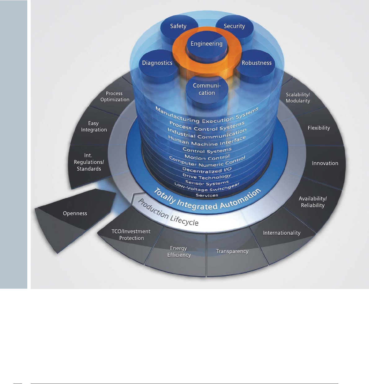
Totally Integrated Automation
Set new productivity standards
for constant competitive advantages
The optimization of processes improves quality, shortens the
time to market and reduces the total cost of ownership.
To survive in increasingly tougher international competition,
today it is more important than ever to consistently tap all
optimization potentials throughout the entire lifecycle of a
plant. At the same time, the perfect balance between quality,
time and costs is the decisive success factor.
With Totally Integrated Automation (TIA) from Siemens, a
seamless offering of perfectly matched products, systems,
and solutions for all hierarchy levels of industrial automation,
you are optimally equipped for this purpose.
© Siemens AG 2011

Totally Integrated Automation 3
Integration of the telecontrol technology in TIA has made it
possible to combine the automation of central plants and the
monitoring of distributed units in a single process control
system.
Homogenous operator control and monitoring using a com-
mon control station, uniform configuration with the same
engineering system, and consistent utilization of hardware
components from the TIA product portfolio result in signifi-
cant savings with regard to investments, operation and
servicing.
Contents
text
SIMATIC PCS 7 TeleControl. . . . . . . . . . . . . . . . . . . . . 4
Process control system with integral
telecontrol center...................................................... 4
Typical application areas............................................ 5
SIMATIC PCS 7 TeleControl system architecture . . . 6
System overview....................................................... 6
Topologies ................................................................ 9
SIMATIC PCS 7 TeleControl system components . . 10
PCS 7 TeleControl Operator System.......................... 10
PCS 7 TeleControl engineering station ..................... 12
Remote terminal units............................................. 13
Telecontrol protocols . . . . . . . . . . . . . . . . . . . . . . . . 14
General/elementary telecontrol functions................ 14
SINAUT ST7 telecontrol protocol .............................. 15
DNP3 telecontrol protocol ....................................... 20
IEC 870-5-101/IEC 870-5-104 telecontrol protocol ... 23
Modbus telecontrol protocol.................................... 26
Redundancy. . . . . . . . . . . . . . . . . . . . . . . . . . . . . . . . 27
Increasing the plant availability ............................... 27
Migration . . . . . . . . . . . . . . . . . . . . . . . . . . . . . . . . . . 28
Migration of existing telecontrol systems................. 28
Application examples. . . . . . . . . . . . . . . . . . . . . . . . 30
Automation of a gas pipeline with slide valve and
measuring stations.................................................. 30
Automation of a sewage treatment plant with
pumping station and stormwater overflow tank....... 31
© Siemens AG 2011
SIMATIC PCS 7 TeleControl4
SIMATIC PCS 7 TeleControl
Process control system with integral telecontrol center
Automation of widely spread process plants
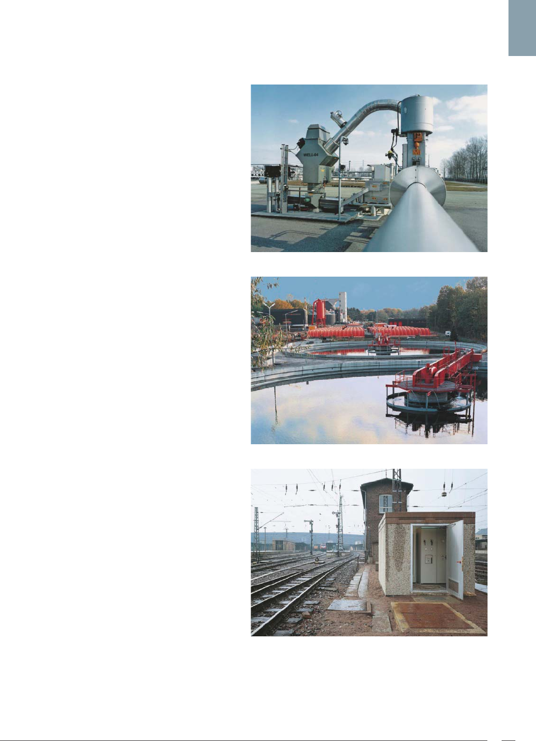
In a number of industries, especially the oil & gas,
water & wastewater, power and transportation sectors,
plants may sometimes be extremely widely spread. Individual
distributed units may even be more than a thousand kilome-
ters away from a central unit with a significantly higher degree
of automation.
With a gas pipeline, for example, several slide valve and mea-
suring stations are distributed between one of the compressor
stations at the beginning of the pipeline and the relief station
at the end.
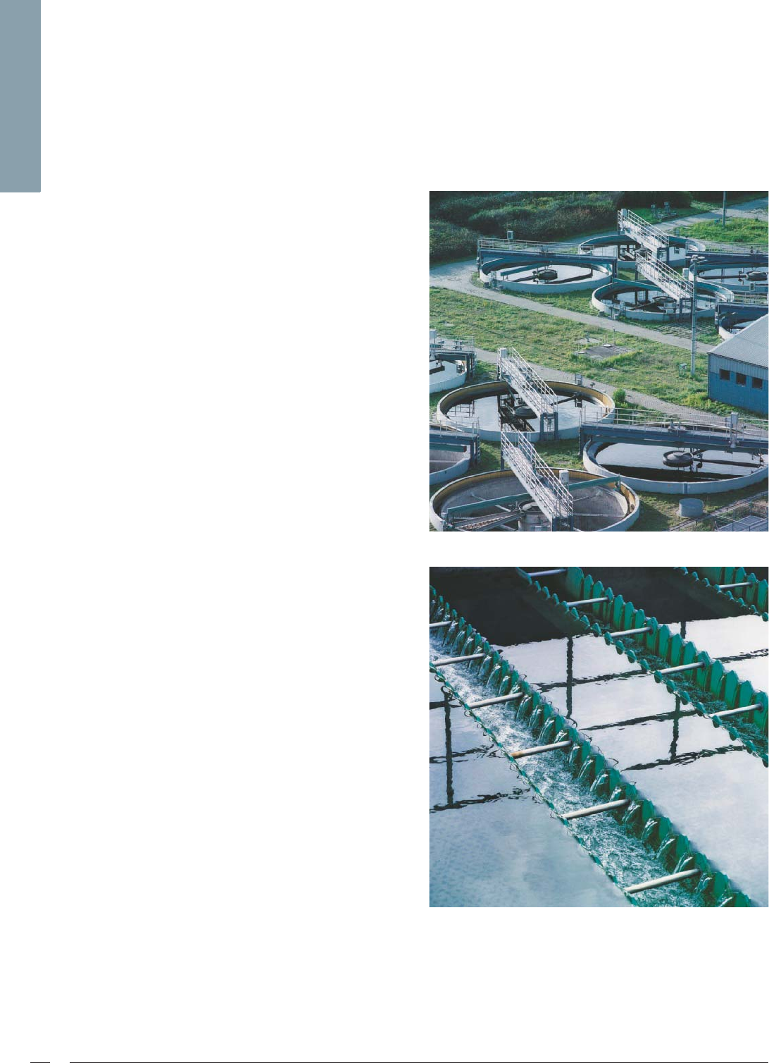
A further example is the canal system of a widely branched
wastewater network connected to a central sewage treatment
plant via pumping stations and stormwater overflow tanks.
In both cases it is necessary to monitor regional units such
as stormwater overflow tanks, pumping stations, slide valve
stations or measuring stations from a far off control center, or
to control them in the context of the complete plant.
Telecontrol systems with which automation functions can be
executed from a remote control center over a telecommunica-
tion network (wide area network/WAN) are the ideal solution
for such tasks.
The automation of a process plant, as described above, is dis-
tributed in conventional implementation concepts between
heterogeneous system levels. Process control systems (PCS)
are normally used for units with a higher degree of automa-
tion, e.g. the central sewage treatment plant. On the other
hand, the local automation of small units with a low degree of
automation (pumping stations, stormwater overflow tanks) is
carried out using simple remote terminal units (RTUs) which
communicate with their control center by means of a telecon-
trol link. To enable global monitoring, all systems of the auto-
mation project (PCS and RTU) are integrated in a host network
control system.
However, it is far more effective if the telecontrol center for
the RTUs is directly integrated into the process control system
using SIMATIC PCS 7 TeleControl. In this case, the network
control system as a superimposed integration level can be
omitted. Uniform process control and totally integrated engi-
neering for central and widely distributed units, together with
simple and convenient data management, result in high effi-
ciency with regard to operation and engineering. Low training
and servicing costs are further positive aspects.
© Siemens AG 2011
SIMATIC PCS 7 TeleControl 5
Typical application areas
Remote control and monitoring of distributed stations, as well
as data recording and transmission, with the following focal
points:
Oil and gas industries
• Compressor, pressure reduction, transfer, block valve, and
metering stations in gas networks
• Pumping and block valve stations in oil pipelines
• Automation on the wellhead of gas and oil wells
• Stations for the injection of water or CO2 in gas or oil fields
Water industry
• Well, pumping and valve stations in water supply networks
and irrigation plants
• Stormwater overflow tanks and pumping equipment in
wastewater networks
• Storage units (elevated tanks)
Energy management, environmental protection,
and transportation
• Equipment for power generation and distribution
• District heat supply
• Traffic control systems
• Tunnels
• Railway stations
• Lighthouses
• Environmental monitoring equipment
• Weather stations
© Siemens AG 2011
SIMATIC PCS 7 TeleControl system architecture6
SIMATIC PCS 7 TeleControl system architecture
System overview
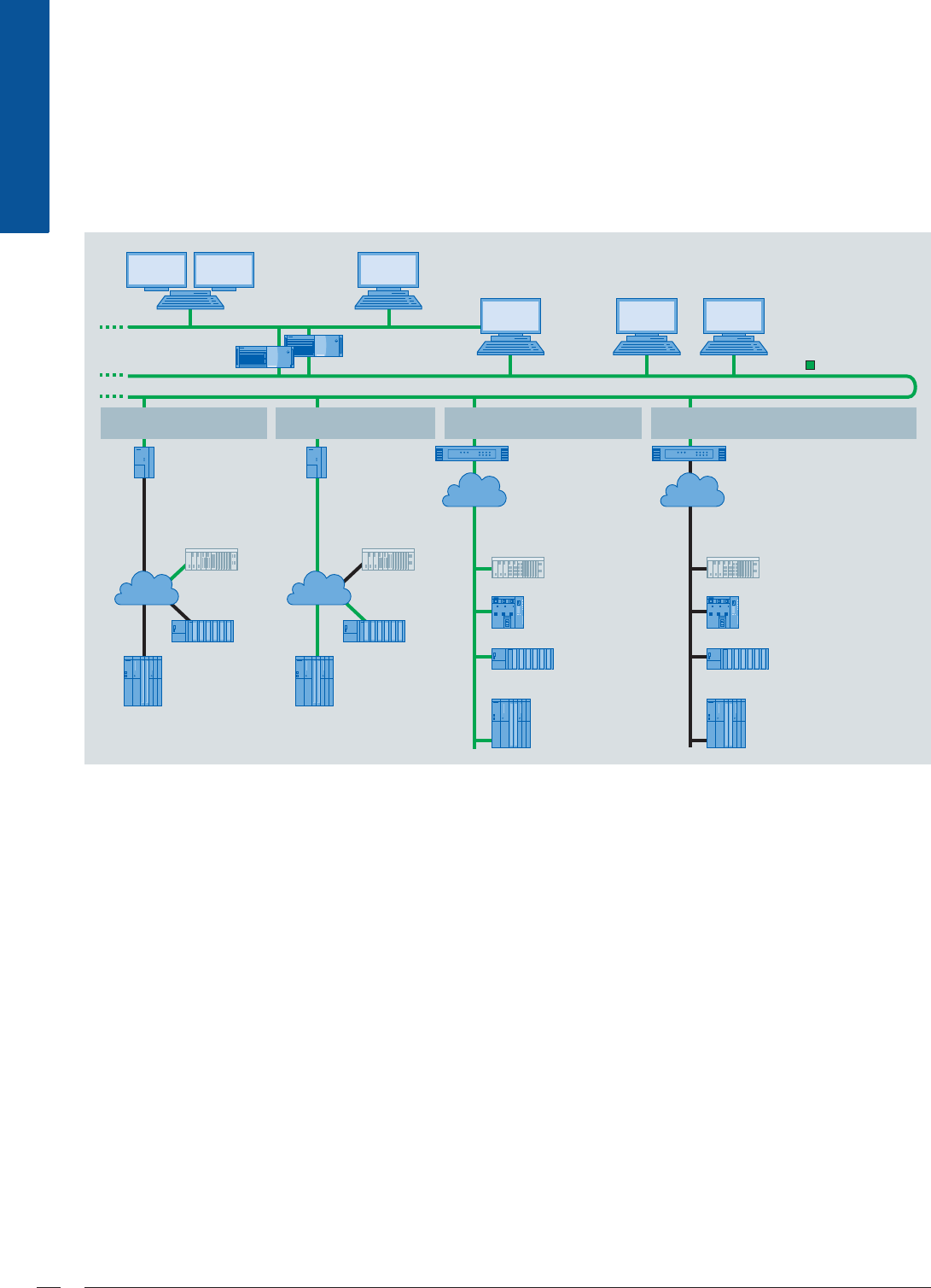
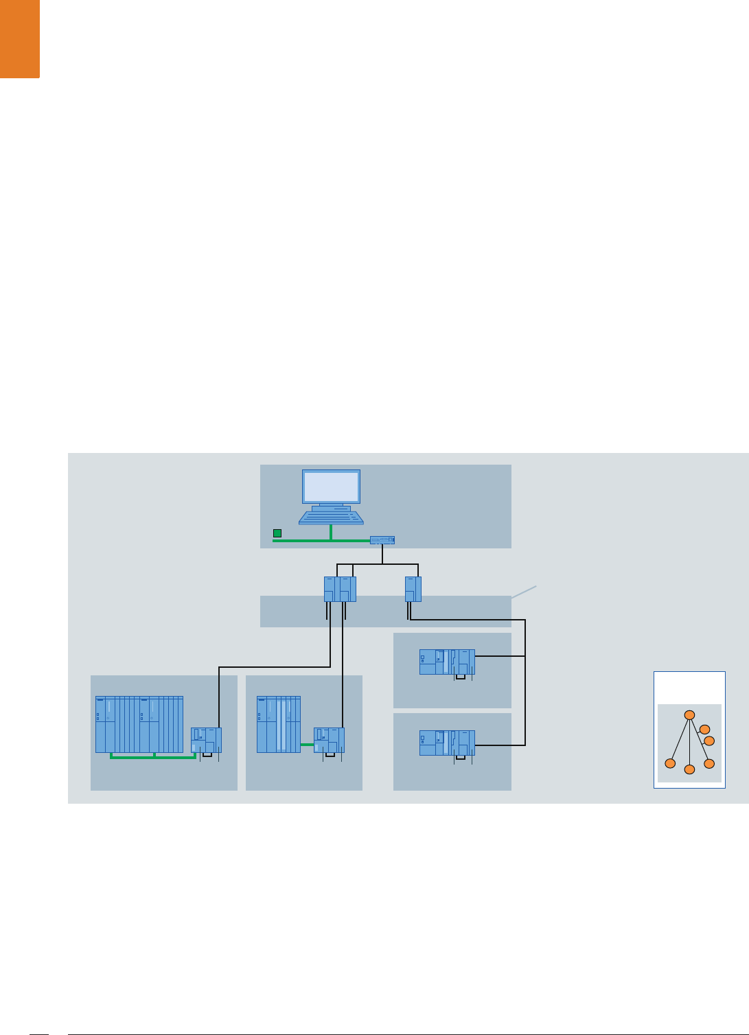
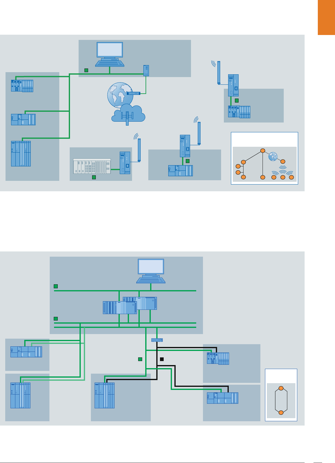
SIMATIC PCS 7 TeleControl system architecture
Integration in process control
The telecontrol center for the outstations (RTU) is integrated
into the process control of the SIMATIC PCS 7 process control
system in the form of an operator station in single station or
server design (also redundant as option). No additional auto-
mation system for conditioning telecontrol-specific data need
be planned in the SIMATIC PCS 7 system. With large quantity
frameworks, a PCS 7 TeleControl operator station (single sta-
tion/server) is preferably responsible only for the telecontrol
mode (dedicated). With small quantity frameworks, a server
or a single station can also control SIMATIC PCS 7 automation
systems (AS) in central plant areas in addition to the telecon-
trol systems (dual-channel mode).
The OS clients of the client/server multi-user system are able
to display data from RTUs and SIMATIC PCS 7 AS - which they
receive from a server with dual-channel functionality or from
two separate servers - together in one process image. Display
is primarily on faceplates for process objects such as motors,
valves etc., but also by means of trend curves and messages.
Engineering
To enable engineering of the PCS 7 TeleControl operator sta-
tion (single station/server), the functions of the engineering
station of the SIMATIC PCS 7 process control system are
expanded by DBA technology (Data Base Automation) and
the SIMATIC PCS 7 TeleControl block library.
Communication with the outstations
(remote terminal units)
For communication with the outstations, SIMATIC PCS 7
TeleControl uses the SINAUT ST7, DNP3 and Modbus protocols
(both via serial and TCP/IP communication connections) as
well as IEC 870-5-101 (serial) and IEC 870-5-104 (Ethernet
TCP/IP).
,QGXVWULDO(WKHUQHW
WAN
WAN WAN
G_PCS7_XX_00175
WAN
S7-400
+ CP 441
S7-300
+ CP 341
PCS 7 TeleControl
OS Server
Engineering Station
PCS 7 OS Clients
PCS 7 OS Single Station
(dedicated or
dual channel)
TIM 4R-IE (ST7)
or Converter
TCP/IP ↔ serial
(DNP3)
Widely distributed
TeleControl outstations
Widely distributed
TeleControl outstations
Widely distributed
TeleControl outstations
TIM 4R-IE (ST7)
or TCP/IP
WAN router
(DNP3)
TCP/IP
WAN router
Converter
TCP/IP ↔ serial
TCP/IP communication:
SINAUT ST7
Serial communication:
SINAUT ST7 or DNP3
TCP/IP communication:
Modbus or IEC 870-5-104
Serial communication:
Modbus or IEC 870-5-101
Third-party RTU
Third-party RTU
(DNP3 only)
Third-party RTU
(DNP3 only)
Third-party RTU
ET 200S with
integral PN CPU
ET 200S with integral
CPU + serial interface
S7-300
+ CP 343 or
PN interface
S7-400
+ CP 443 or
PN interface
S7-400
+ TIM 4R-IE or
TIM 4R-IE DNP3
S7-400
+ TIM 4R-IE or
TIM 4R-IE DNP3
S7-300
+ TIM 3V-IE or
TIM 3V-IE DNP3
S7-300
+ TIM 3V-IE or
TIM 3V-IE DNP3
© Siemens AG 2011

SIMATIC PCS 7 TeleControl system architecture 7
The serial RTU link is possible at low cost via the following
components which can be connected directly to the PCS 7
TeleControl OS (single station or server):
•SINAUT TIM communication modules
(SINAUT ST7 telecontrol protocol)
•TCP/IP converters – serial
(DNP3, Modbus, IEC 870-5-101 telecontrol protocols)
Devices from MOXA or Lantronix can be used as serial
TCP/IP converters.
By means of Ethernet TCP/IP, the RTUs can be connected di-
rectly or via TCP/IP WAN routers to the SIMATIC PCS 7 system
bus (SINAUT ST7, DNP3, Modbus, IEC 870-5-104 telecontrol
protocols). When using the SINAUT ST7 telecontrol protocol,
the SINAUT TIM communication module can be used in addi-
tion to the TCP/IP WAN router or as an alternative.
Telecontrol communication over the wide area network is
largely determined by the communication infrastructure
which already exists. Various transmission media such as
dedicated line, analog or digital telephone networks, wireless
networks (GSM or private), DSL or GPRS can also be combined
with each other.
Outstations (remote terminal units)
Since the requirements of the widely distributed units with re-
gard to scope and performance of the automation functions
are usually in the low to mid range, controllers with minimum
dimensioning are normally used as RTUs.
SIMATIC PCS 7 TeleControl particularly supports the following
types of RTU for distributed automation on site:
•Controllers integrated in SIMATIC ET 200S
(Modbus, IEC 870-5-101/104 telecontrol protocols)
•SIMATIC S7-300/S7-300F controllers
(SINAUT ST7, DNP3, Modbus, IEC 870-5-101/104 telecon-
trol protocols)
•SIMATIC S7-400/S7-400F controllers
(SINAUT ST7, DNP3, Modbus, IEC 870-5-101/104 telecon-
trol protocols)
•SIMATIC S7-400H/S7-400FH redundant controllers
(IEC 870-5-101/104 and DNP3 telecontrol protocols)
In addition to these, appropriate third-party RTUs can also be
connected to the telecontrol center in SIMATIC PCS 7 by
means of the DNP3, Modbus, IEC 870-5-101/104 telecontrol
protocols.
SIMATIC PCS 7 TeleControl cannot only integrate newly config-
ured RTUs into SIMATIC PCS 7, it can also migrate units which
already exist outdoors by means of DNP3, IEC 870-5-101/104,
Modbus or EDC drivers. The Data Base Automation (DBA) soft-
ware substantially facilitates project-specific adaptation of the
system and importing of existing configurations during migra-
tion. Extensions can be added during plant operation if neces-
sary.
© Siemens AG 2011

SIMATIC PCS 7 TeleControl system architecture8
1)
Data buffering is limited to two SIMATIC S7 data blocks. Depending on the
SIMATIC CPU, this corresponds to approx. 800 to 3 200 buffered frames.
Spectrum of outstations and integration versions
Telecontrol protocol SINAUT ST 7 Modbus DNP3 IEC 870-5-
101 IEC 870-5-
104
Type of communica-
tion
Serial Ethernet
TCP/IP
Serial Ethernet
TCP/IP
Serial Ethernet
TCP/IP
Serial Ethernet
TCP/IP
Interface on the
PCS 7 TeleControl OS
TIM 4R-IE TCP/IP WAN
router or/and
TIM 4R-IE
TCP/IP
converter
–
serial
TCP/IP
WAN router
TCP/IP
converter
–
serial
TCP/IP
WAN router
TCP/IP
converter
–
serial
TCP/IP
WAN router
RTU/interface
ET 200S with inte-
gral CPU (corre-
sponds to S7-314)
– – IM 151-7 CPU
or
IM 151-8
PN/DP CPU
as well as
1 SI module
Modbus
IM 151-8
PN/DP CPU
+ S7-
OpenModbus
software /
TCP PN-CPU
– – IM 151-7 CPU
or
IM 151-8
PN/DP CPU
as well as
1 SI module +
SIPLUS RIC
library
IM 151-8
PN/DP CPU +
SIPLUS RIC
library
S7-300/
S7-300F
TIM 3V-IE TIM 3V-IE CP 341 CP 343 +
SW library
TIM 3V-IE
DNP3
TIM 3V-IE
DNP3
CP 341 +
SIPLUS RIC
library
CP 343 +
IEC on S7
or integral
PN interface
+ SIPLUS RIC
library
S7-400/
S7-400F
TIM 4R-IE TIM 4R-IE CP 441 CP 443 +
SW library
TIM 4R-IE
DNP3
TIM 4R-IE
DNP3
CP 441 +
SIPLUS RIC
library
CP 443 +
SIPLUS RIC
library
or integral
PN interface
+ SIPLUS RIC
library
S7-400H/
S7-400FH
– – – – TIM 4R-IE
DNP3
TIM 4R-IE
DNP3
ET 200M +
2 x CP 341 +
SIPLUS RIC
library
CP 443 +
SIPLUS RIC
library
Third-party station – – Depends on type of station Depends on type of station Depends on type of station
Dialup lines 4 – – – 4 – – –
Dedicated line and
radio networks 4 4 4 4 4 4 4 4
Master-slave 4 4 4 4 4 4 4 4
Peer-to-peer 4 4 – – – – 4 4
Mesh networks 4 4 – – 4 4 4 4
Time tagging in RTU 4 4 – – 4 4 4 4
RTU time synchroniza-
tion 4 4 – – 4 4 4 4
Data buffering in RTU 4 4 – – 4 4 4 1) 4 1)
Routing with
SIMATIC PDM 4 4 – – – – – 4
International standard
– –
4
(many ver-
sions)
4
(many ver-
sions)
4 4 4 4
© Siemens AG 2011
SIMATIC PCS 7 TeleControl system architecture 9
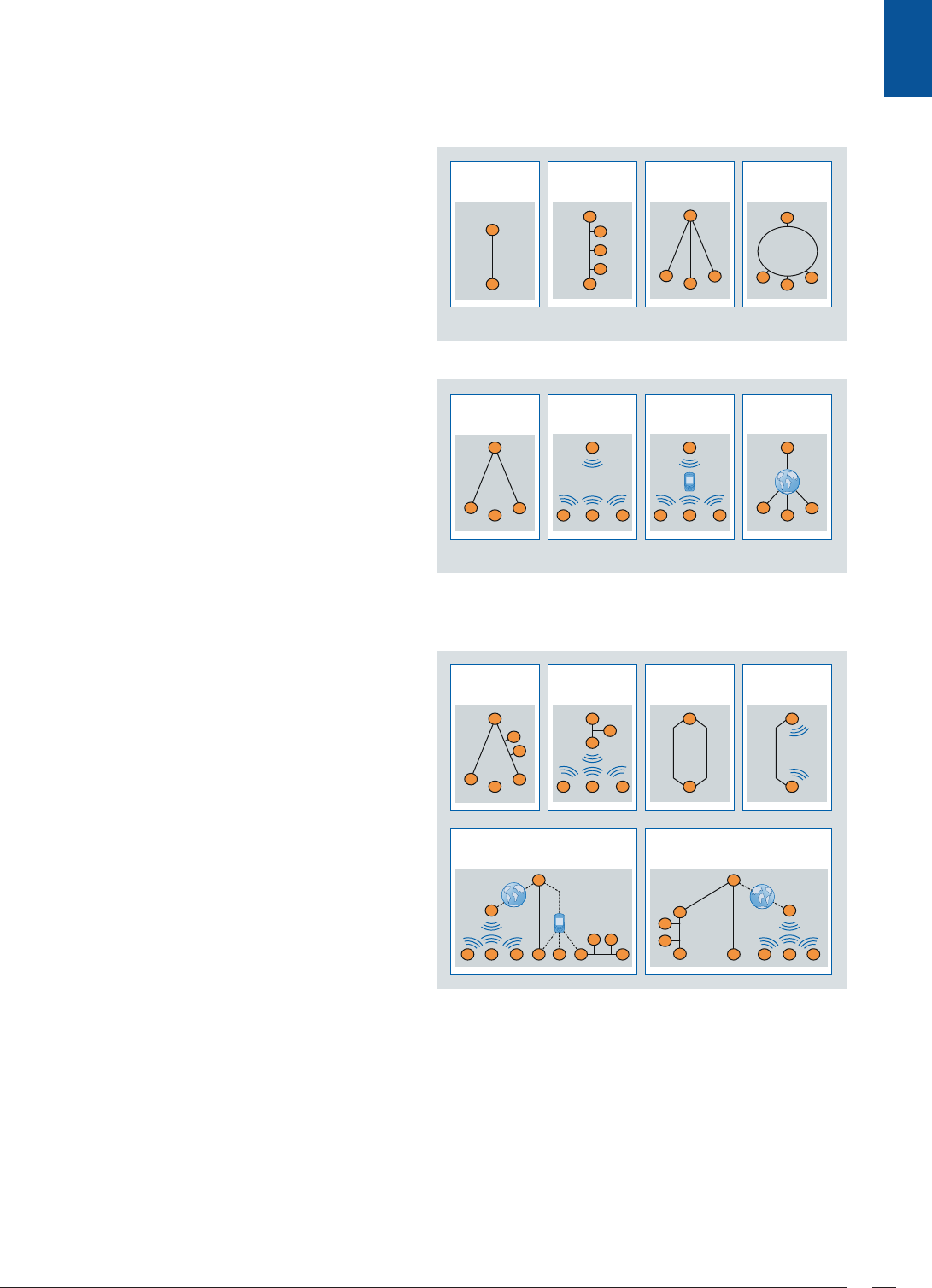
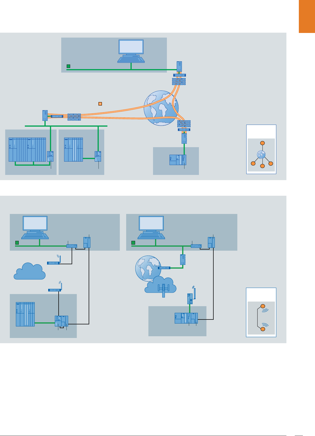
Topologies
Basic topologies
Differently structured telecontrol networks can be implement-
ed in the wide area network (WAN) based on the following
four basic topologies.
Media versions
Depending on the support provided by the selected telecon-
trol protocol, various transmission media are available for
these basic topologies, e.g. dedicated line, private wireless
networks, mobile radio networks, dial-up networks (wire-
less/landline), DSL over Internet.
Some of these media versions are shown in the example of the
star topology.
Combinations of basic topologies and media versions
Through a combination of several basic topologies of the
same or different media versions, it is additionally possible to
design more complex network topologies, even with redun-
dant communication paths.
This allows adaptation to the respective local conditions and
to the existing infrastructure.
Point-to-
point
Multi-point Star Ring
Star via
dedicated line
Star via
wireless
Dial-up
network via
wireless
Star via
Internet
Star +
multi-point
Complex network structure,
example of SINAUT ST7/DNP3
communication
Complex network structure,
example of IEC 870-5-104
communication
Nodes Path
redundancy,
1 medium
Path
redundancy,
2 media
© Siemens AG 2011
SIMATIC PCS 7 TeleControl system components10
SIMATIC PCS 7 TeleControl system components
PCS 7 TeleControl Operator System
Single-user and multi-user systems
Depending on the magnitude of the automation project and
the required number of operator stations, the SIMATIC PCS 7
TeleControl Operator System can be configured either as a sin-
gle-user system (PCS 7 TeleControl OS single station) or as a
multi-user system with client/server architecture:
• Single-user system
- Up to 5 000 process objects
- Up to approx. 3 000 measuring points
- Low number of operator stations
• Multi-user system (client/server)
- Up to 8 500 process objects per OS server
- Up to approx. 5 000 measuring points per OS server
- Up to 32 operator stations (OS clients)
In a single-user system architecture, all operation and moni-
toring functions for a complete project (plant/unit) are con-
centrated in one station.
A multi-user system has up to 32 operator stations (OS clients)
which are supplied with data from one or more servers
(OS server or PCS 7 TeleControl OS server) via the terminal
bus.
The multi-client architecture of the multi-user system allows
an OS client to call data from various servers, e.g. from two
separate servers for local units and for units connected by
means of PCS 7 TeleControl.
The PCS 7 TeleControl OS server of the multi-user system can
also have a redundant design. All internally generated infor-
mation (e.g. alarm states or results of calculations) is matched
in the redundant pair of PCS 7 TeleControl OS servers.
The graduated scalability of the process objects of PCS 7
TeleControl OS single station and PCS 7 TeleControl OS server
permits fine and flexible matching of the SIMATIC PCS 7
TeleControl Operator System to the size of the respective
automation project.
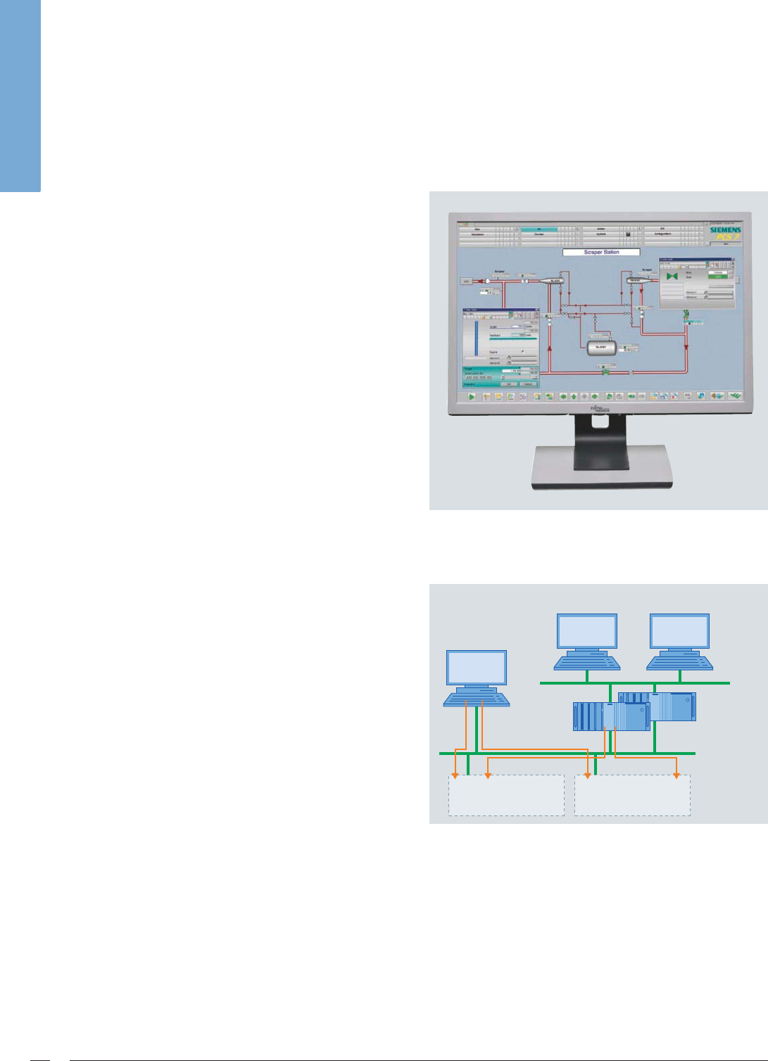
Uniform process control for central and remote units
Dual-channel operation
Dual-channel operation with single-user and multi-user systems
PCS 7 TeleControl OS single station and PCS 7 TeleControl OS
server are preferably used just for telecontrol functions (dedi-
cated), but can also access central SIMATIC PCS 7 plant areas
via an additional second channel in the case of small quantity
frameworks (double-channel operation). In this way, data
from the RTUs of the telecontrol system can be displayed in
one process image together with data from SIMATIC PCS 7 AS.
G_PCS7_XX_00261
· · ·
OS clients
OS single station
SIMATIC PCS 7
+ TeleControl
(dual channel)
PCS 7
automation system
TeleControl
RTUs
OS server
(single or
redundant)
© Siemens AG 2011

SIMATIC PCS 7 TeleControl system components 11
PCS 7 TeleControl blocks for system-conformant operator
control and monitoring
The RTUs are integrated into the PCS 7 TeleControl Operator
System by means of the PCS 7 TeleControl blocks such that
there is no difference for the operator with regard to operat-
ing philosophy and alarm behavior for the central or remote
automation functions.
The blocks required for data conditioning and display are
saved in a library. These blocks support SIMATIC PCS 7 compli-
ant operator control by means of symbols and faceplates, as
well as the hierarchy of SIMATIC PCS 7 fault messages.
In addition to blocks for processing of process data, the
library also contains blocks for diagnostics and for control
of communication. If necessary, the supplied basic library can
be extended by new script-based block types specific to the
project by using the DBA Type Editor.
Long-term archiving and
logging
The PCS 7 TeleControl Operator System includes a high-perfor-
mance cyclic archive based on Microsoft SQL Server for time-
limited saving of process values and messages/events. Data
from this cyclic archive can be exported time-controlled or
event-controlled to a long-term archive (StoragePlus/central
archive server).
The logging system of the PCS 7 TeleControl Operator System
supports the display and evaluation of data recorded during
operation by means of various predefined types of protocol
which can also be matched individually:
• Message sequence report
• Message and archive log
• Measured value log
• Operator input log
• System message log
•User log
The logs saved in EMF format can be previewed on the screen,
and can be printed manually or time- or event-controlled.
In order to comply with statutory directives and standards it
may be necessary to provide special proof, e.g. proof of con-
formity with the ATV M260 standard for sewage treatment
plants. The SIMATIC PCS 7 add-on product ACRON equipped
with additional functionalities for long-term archiving and
logging provides excellent support for this purpose.
© Siemens AG 2011
SIMATIC PCS 7 TeleControl system components12
PCS 7 TeleControl engineering station
Engineering station of the SIMATIC PCS 7 process control system
To enable engineering of the PCS 7 TeleControl operator sta-
tion (single station/server), the functions of the engineering
station of the SIMATIC PCS 7 process control system are ex-
panded by DBA technology (Data Base Automation) and the
SIMATIC PCS 7 TeleControl block library.
Data Base Automation (DBA)
Engineering can be automated efficiently and in conformance
with SIMATIC PCS 7 using the DBA technology. DBA supports
plant expansion during ongoing operation, and facilitates
project-specific adaptation of the system as well as importing
of existing configurations in the course of migration.
The DBA executed in the engineering station automatically
generates the OS runtime database with the display hierarchy,
required variables, alarms, alarm messages and alarm priori-
ties, as well as the specific faceplates and block symbols.
The display hierarchy is the basis for navigation between the
process displays, for alarm management, and for implementa-
tion of safety measures. DBA positions the type-specific block
symbols, e.g. measured value, counter value, motor or gate
valve, in the process images. These symbols are linked to the
corresponding function blocks and faceplates through the da-
tabase. Manual configuration is mainly limited to the design
and positioning of the static graphic elements, e.g. pipes or
tanks.
SIMATIC PCS 7 TeleControl block library
In addition to the SIMATIC PCS 7 TeleControl basic library,
new user blocks can also be defined using the DBA type editor.
During database generation, the user blocks are treated like
the blocks from the basic library.
Using the DBA type editor it is possible to assign the frequently
unstructured variables of an RTU once to a block type and to
display the variable structured on the operator station via the
block's faceplate.
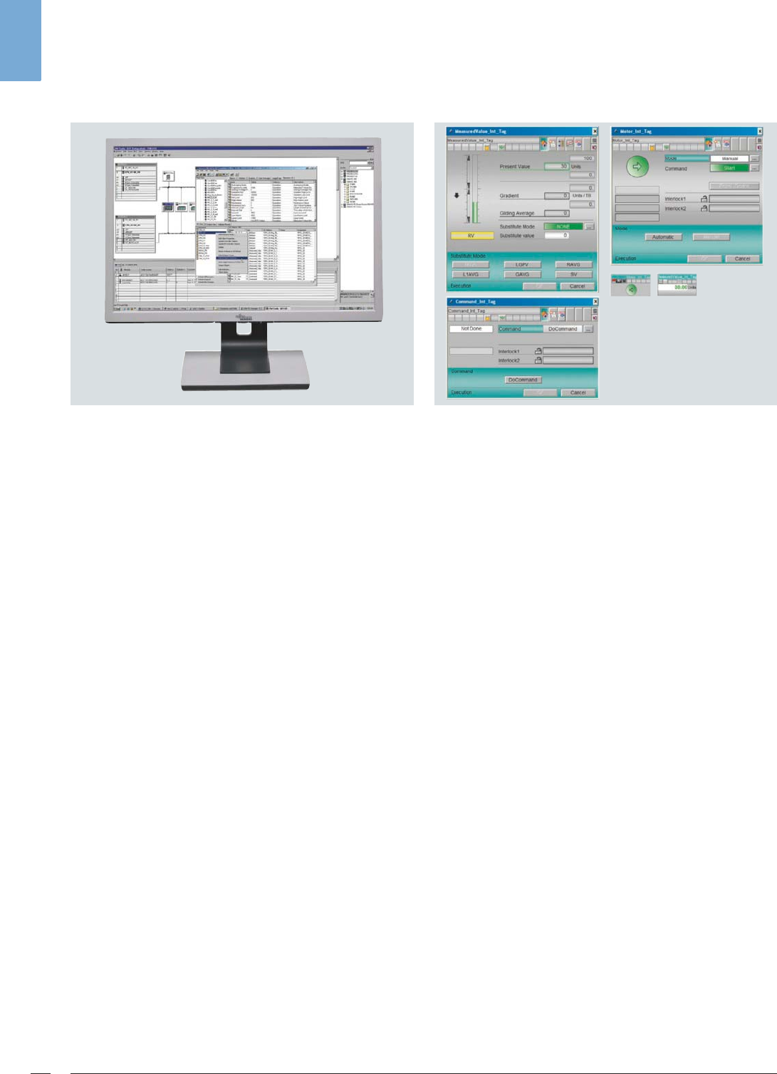
SIMATIC PCS 7 TeleControl blocks
The PCS 7 TeleControl OS symbols, faceplates and diagnostics
displays created in conformance with SIMATIC PCS 7 take into
account the specific features of telecontrol applications. This
is demonstrated, for example, by the example of the counter
block which offers versatile conditioning options for informa-
tion on transported or processed quantities. At least one
OS faceplate and one OS symbol are available for each type
of block.
In addition to arrangement of information in a variable struc-
ture, the user blocks generated with the DBA type editor can
also calculate derived values using Visual Basic scripts in the
server. This results in numerous possibilities for extending the
functionality and for adapting the system to individual cus-
tomer requirements.
Type-specific OS faceplates and OS symbols for the user blocks
can be created using the standard tools for SIMATIC PCS 7
OS engineering (Graphics Designer and Faceplate Designer).
© Siemens AG 2011
SIMATIC PCS 7 TeleControl system components 13
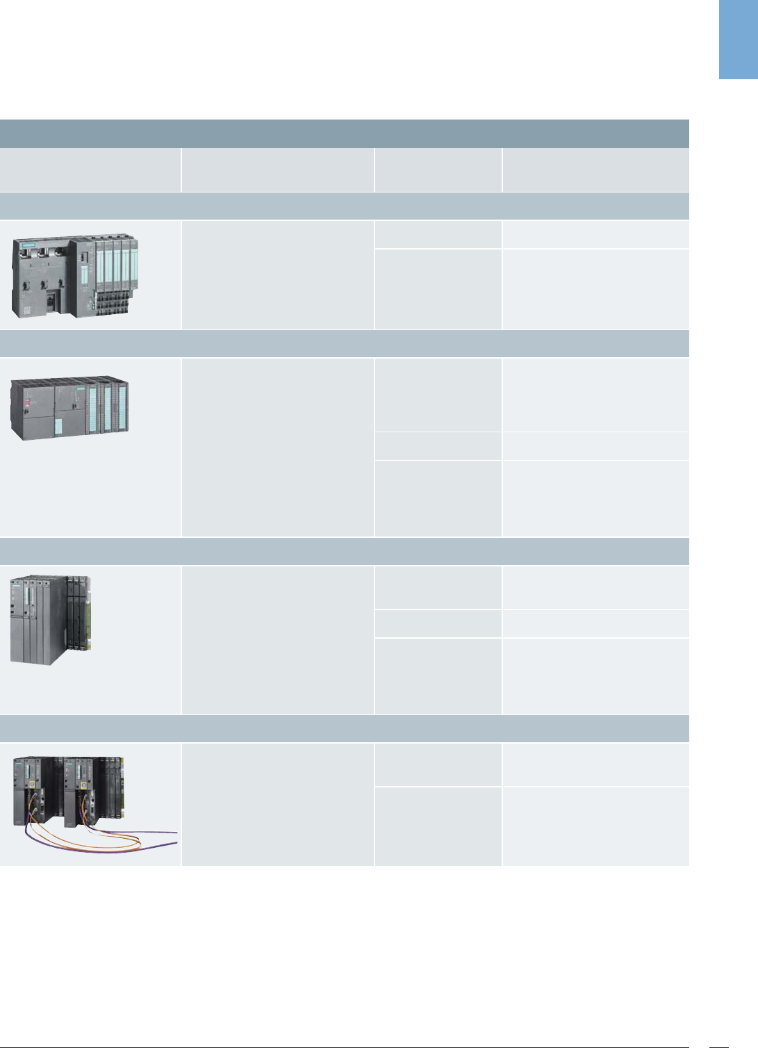
Remote terminal units
The remote control units supported by SIMATIC PCS 7
TeleControl have a performance classified as Small, Medium
or Large.
Controllers of SIPLUS extreme design are also available in all
performance classes, and can be operated under extreme con-
ditions, e.g. ambient temperatures from -25 °C to +70 °C, con-
densation or exposure to media.
In addition, the SIMATIC S7-300F and S7-400F controllers can
be used to implement safety-related applications on site and
automatically set the plant to a safe status in the event of a
dangerous fault.
Classification of the remote terminal units
RTU Applications
Possible tele-
control protocols
Information points/
buffer size
RTU Small: controller integrated in SIMATIC ET 200S
RTU with up to approx. 30 I/Os
For small, cost-sensitive applica-
tions
• Modbus No buffering
• IEC 870-5-101
• IEC 870-5-104
Up to approx. 200 information
points
Buffer size:
800 information points
RTU Medium: SIMATIC S7-300/S7-300F controller
RTU with up to approx. 100 I/Os
For medium-sized applications;
extremely flexible configuration
S7-300F for safety-related appli-
cations
•SINAUT ST7
•DNP3
TIM buffering
(up to 16 000 frames or up to
32 000 frames with TIM 3V-IE
Advanced)
• Modbus No buffering
• IEC 870-5-101
• IEC 870-5-104
Up to approx. 2 000 informa-
tion points
Buffer size: 800 to 3 200 infor-
mation points
RTU Large: SIMATIC S7-400/S7-400F controller
RTU with up to approx. 500 I/Os
For larger applications requiring
increased performance
S7-400F for safety-related appli-
cations
•SINAUT ST7
•DNP3
TIM buffering
(up to 56 000 frames)
• Modbus No buffering
• IEC 870-5-101
• IEC 870-5-104
Up to approx. 5 000 informa-
tion points
Buffer size: 3 200 information
points
RTU Large: SIMATIC S7-400H/S7-400FH controller
Like S7-400/S7-400F •DNP3 TIM buffering
(up to 56 000 frames)
• IEC 870-5-101
• IEC 870-5-104
Up to approx. 5 000 informa-
tion points
Buffer size: 3 200 information
points
© Siemens AG 2011

General/elementary telecontrol functions14
Telecontrol protocols
General/elementary telecontrol functions
Telecontrol systems use special protocols to implement data
transmission between the control center and the outstations
(RTUs) at the process level for the automation functions on
site. These telecontrol protocols manage the secure and error-
free data transmission over the WAN even with a low band-
width and poor transmission quality.
In addition to short transmission times for the information,
this task requires effective protection of the frames against:
• Undetected bit errors
• Undetected frame errors resulting from synchronization
errors
• Undetected loss of information
• Frame falsification
• Segregation or fault in related information
This particularly applies to event-controlled frames over trans-
mission channels with a limited bandwidth and uncertain
noise response.
Since irregular bit sequences are compiled for data transmis-
sion, no limitation in codes must exist.
Time tagging
When linking RTUs by means of SINAUT ST7, DNP3,
IEC 870-5-101 or IEC 870-5-104 telecontrol protocol, the raw
data in the outstations is provided with a time tag and trans-
mitted to the PCS 7 TeleControl OS (server/single station)
acting as control center. Adaptation, further processing, and
archiving are carried out here. This procedure is appropriate
for the event-based principle of operation of the telecontrol
protocol as well as the subsequent chronological processing
of data previously buffered in the outstation.
Clock synchronization
The PCS 7 TeleControl OS is the clock master for the RTUs
connected by means of SINAUT ST7, DNP3, IEC 870-5-101 or
IEC 870-5-104, and regularly synchronizes their date and time
via the telecontrol connection. Switching over between sum-
mertime and wintertime is also considered during the syn-
chronization.
Data buffering
The SINAUT ST7, DNP3, IEC 870-5-101 and IEC 870-5-104
telecontrol protocols support reliable on-site intermediate
buffering of the data including time tag, e.g. if a communi-
cation path is faulty or a station has failed. In addition, inter-
mediate buffering of data can also be an effective means
for reducing connection costs in the dial-up network.
A data update for all participating communication partners
is performed automatically following debugging or restarting
of the failed station. Important events are not lost, and the
integrity of the control center archive is assured.
© Siemens AG 2011
SINAUT ST7 telecontrol protocol 15
SINAUT ST7 telecontrol protocol
Overview of SIMATIC PCS 7 TeleControl with SINAUT ST 7 telecontrol
protocol
The telecontrol system based on the SINAUT ST7 telecontrol
protocol is used for fully-automatic monitoring and control of
widely distributed outstations (RTUs) which exchange data
with each other and with one or more control centers over a
wide variety of WAN (Wide Area Network) media.
SIMATIC S7-300/S7-300F and SIMATIC S7-400/S7-400F con-
trollers are used for the outstations and node stations, and
SIMATIC PCS 7 with SIMATIC PCS 7 TeleControl for the control
center. Further hardware and software components round off
the range of products:
• TIM communication modules
• MD modem modules
•GSM/GPRS components
• TCP/IP routers and switches
• SCALANCE S612 and S613 security modules
• Dedicated-line accessories
•Cables
• SINAUT ST7 engineering software, comprising:
- SINAUT TD7 library with blocks for the data point objects
of the SIMATIC S7 CPU or the TIM module
- SINAUT ST7 engineering package for configuration of
stations, networks and connections as well as for diag-
nostics
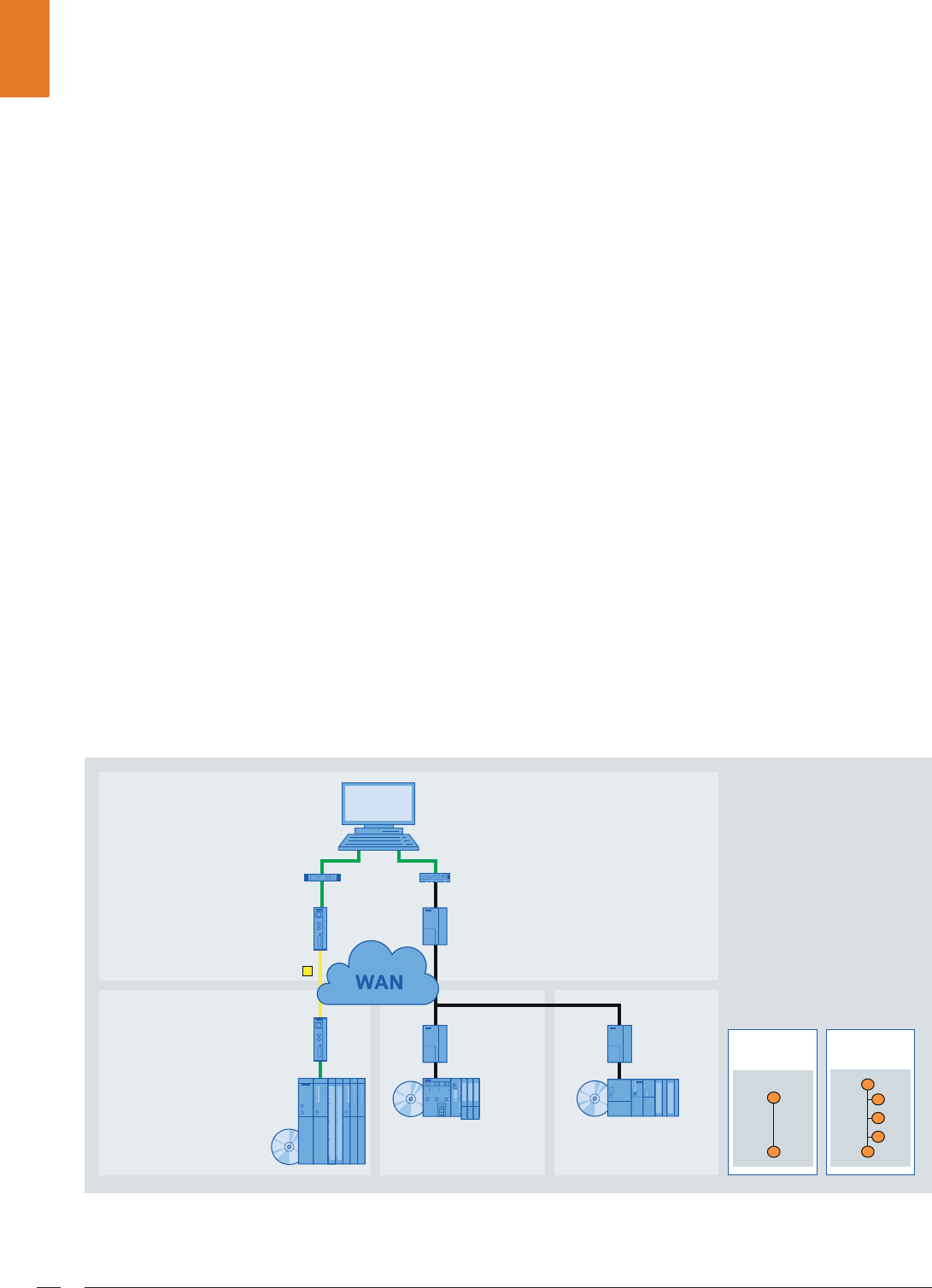
In order to implement complete hierarchical telecontrol net-
works, the basic topologies of point-to-point, multi-point, star
and ring can be configured using classic or also TCP/IP-based
media, and combined flexibly independent of the infrastruc-
tural conditions. SINAUT ST7 is thus distinguished by a wide
range of possible selections and combinations.
Industrial Ethernet
TIM 4R-IE
G_PCS7_XX_00262
IP-based
WAN
Classic
WAN
SINAUT ST7 stations
6,0$7,&3&6ZLWK6,0$7,&3&67HOH&RQWURO
S7-300
with TIM 3V-IE
S7-400
and
TIM 4R-IE
© Siemens AG 2011
SINAUT ST7 telecontrol protocol16
SINAUT ST7 - example of classic dedicated network (star + multi-point topologies)
SINAUT ST7 - example of classic mobile radio network (GSM) with CSD data service (star topology)
Classic WAN media
• Dedicated copper line, private or rented
• Private radio network (optionally with time slot procedure)
• Analog telephone network
• Digital ISDN network
• Mobile radio network GSM
TIM 4R-IE
G_PCS7_XX_00263
TIM 3V-IE
RS 485
MD2 MD2
· · ·
· · ·
MD2
TIM 3V-IE MD2
TIM 3V-IE MD2TIM 4R-IE MD2
TIM 4R-IE MD2
MD2
Ethernet
RTU S7-400
RTU S7-400
RTU S7-300 RTU S7-300
RTU S7-300
Control center
SIMATIC PCS 7 TeleControl
Dedicated network
with star topology
Range without repeaters (example)
with conductor cross-section 0.8 mm
- 1 200 bit/s max. 33 km
- 2 400 bit/s max. 27 km
- 19 200 bit/s max. 11 km
Star +
multi-point
TIM 4R-IE
TIM 3V-IE
MD 720-3
G_PCS7_XX_00264
MD720-3
MD720-3
MD720-3
MD720-3
MD720-3
TIM 4R-IE
Ethernet
RTU S7-400
TIM 4R-IE
RTU S7-400
RTU S7-300
TIM 3V-IE
RTU S7-300
Control center
SIMATIC PCS 7 TeleControl
Option:
redundant
network access
in the master
station
Mobile
wireless
network
Dial-up
network via
wireless
© Siemens AG 2011

SINAUT ST7 telecontrol protocol 17
SINAUT ST7 - example of secure TCP/IP-based connection over Internet via DSL (star topology)
SINAUT ST7 - example of redundant telecontrol connections (point-to-point topology)
TCP/IP-based WAN media
• Special radio network optimized for Ethernet, e.g. with
SCALANCE W industrial wireless LAN components
• SCALANCE X switches with optical ports and fiber-optic
cables for distances up to 120 km
• Public network and Internet via DSL or GPRS
• Broadband system such as OTN, PCM30, etc.
To achieve redundant data transmission, it is also possible to
connect an outstation via two transmission paths to the con-
trol center in the SIMATIC PCS7 process control system or to a
node station. It is irrelevant whether the two paths are of the
same type or different, e.g. dedicated line with telephone net-
work/ISDN and GPRS.
TIM 4R-IE
· · ·
TIM 3V-IETIM 4R-IE
Ethernet
RTU S7-400
RTU
S7-300
TIM 3V-IE
RTU
S7-300
SCALANCE
S612/613
SCALANCE
S612/613
G_PCS7_XX_00265
Control center
SIMATIC PCS 7 TeleControl
DSL router
DSL
router Firewall
Firewall
Internet
Firewall
DSL router Star via
Internet
931WXQQHO
MD741-1
Ethernet
TIM 3V-IE
Advanced
RTU S7-300
TIM 4R-IE MD2 MD2
TIM 4R-IE MD2
RTU S7-400
Ethernet
TIM 4R-IE MD2
G_PCS7_XX_00266
SCALANCE
S612/613
Control center
SIMATIC PCS 7 TeleControl
Radio
network
GPRS
network
Dedicated
line
Redundant transmission path:
classic WAN + classic WAN
Control center
SIMATIC PCS 7 TeleControl
Internet
Dedicated
line
Redundant transmission path:
classic WAN + TCP/IP-based WAN
Path
redundancy,
2 media
DSL router
© Siemens AG 2011
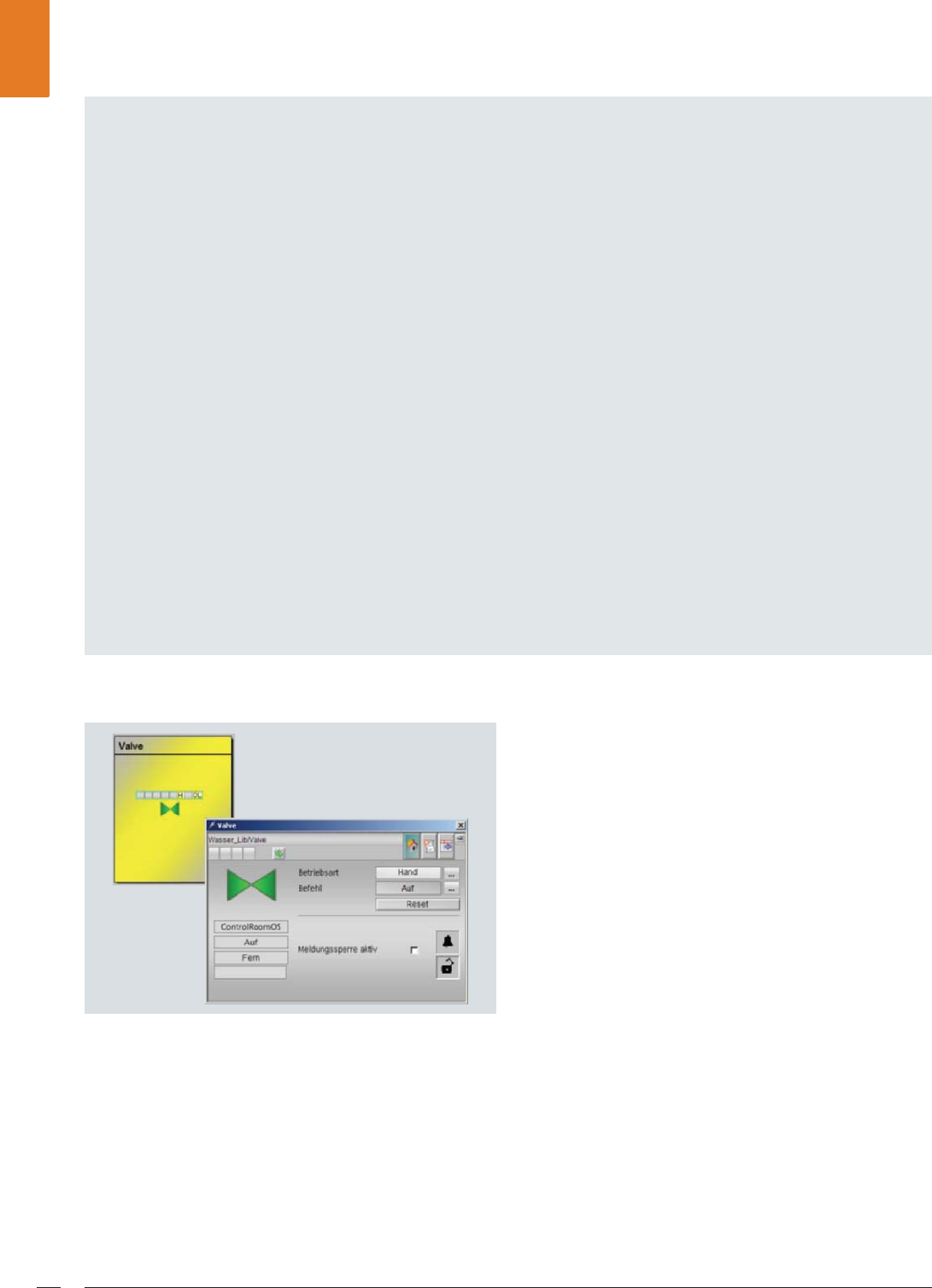
SINAUT ST7 telecontrol protocol18
SIMATIC water library: block symbol and faceplate for a valve
Technological configuration with the
SIMATIC water library
The SIMATIC water library from Siemens supports effective
configuration of the SIMATIC PCS 7 process control system
with technological function blocks for implementing applica-
tions for water supply and disposal.
These technological function blocks can now also be used on
the basis of the SINAUT ST7 telecontrol protocol. The telecon-
trol functions are integrated using additive blocks in the CFC,
i.e. without modifying the existing technological function
blocks or the associated block symbols and faceplates. The
philosophy of SIMATIC PCS 7 TeleControl with regard to uni-
form process control of central and remote units using an
operator system is thus extended in the direction of uniform
engineering. Standardization and reuse of the ready-made
functions significantly reduces the requirements for engi-
neering, testing and training, as well as maintenance and
updating.
Special characteristics
of SINAUT ST7 communication
Up to 10 000 stations can be addressed with SINAUT ST7.
Information on the source and target addresses is included
in the message frames. The functionality of SINAUT ST7
communication is particularly characterized by the follow-
ing features:
Change-driven data transmission
• Change-driven transmission of process data between
RTUs as well as between an RTU and the control center
• Signaling of failures in connections, RTUs or the control
center
• Automatic data updating for all communication part-
ners involved following troubleshooting and following
the startup of an RTU or control center
Chronological processing of process data
• Time tagging of all data frames at the place of origin al-
lows process data to be archived by the process control
system in the correct chronological order
• The time of the SINAUT ST7 stations in the WAN can
be synchronized via SIMATIC PCS 7 (including summer-
time/wintertime switchover)
Local data storage
• Depending on the version, the TIM communication
module can temporarily store (for several hours or even
days) up to 56 000 message frames should the connec-
tion or the communication partner fail
• Intermediate storage of message frames of lower prior-
ity in the case of priority-controlled data transmission
(with dial-up networks or quantity-dependent data
transmission costs)
Remote programming and remote diagnostics
• Remote diagnostics and remote programming over the
WAN using the "PG routing" function
• PG routing shares the available bandwidth with the pro-
cess data transmission, but has a higher priority
• Uploads, downloads, remote diagnostics, firmware up-
grades or changes in automation functions on the sta-
tions can be carried out online from the control center
in SIMATIC PCS 7
Alarm output per text message
• The RTUs can send text messages depending on events
in order to alarm personnel on call
• Receipt of messages can be acknowledged from a
mobile phone
• Depending on the services offered by the mobile radio
provider, the text message can also be output as an
e-mail, fax or voice mail
© Siemens AG 2011

SINAUT ST7 telecontrol protocol 19
Operating modes
The communication mode between the control center and
outstation (RTU) depends on the support provided by the tele-
control protocol, the configuration of the telecontrol commu-
nication, and the type of WAN.
The SINAUT ST 7 telecontrol protocol supports the following
operating modes:
•Polling
- Control of data exchange by the TIM module of the con-
trol center
- The TIM of the control center calls the outstations and
node stations one after the other
- Stations with modified data (since the last transmission)
send this when called
- Stations without modified data only acknowledge the
call
- Transmission of control center data for the stations in
between the calls
- Data exchange using internode communication between
the stations is possible via the polling TIM of the control
center
• Polling with time slot procedure
- Operating mode for a radio network with division of the
radio frequency between several providers
- Typically 6 s/min (time slot) for each provider for data
exchange
- Data exchange during the time slot is carried out as
described under "Polling"
- Following the data exchange, the frequency swaps to the
next provider
- Data exchange using internode communication between
the stations is possible via the polling TIM of the control
center
- Control of the polling TIM by DCF77 or GPS radio-con-
trolled clock for exact observation of the time slot
• Multi-master polling with time slot procedure
- Operating mode for communication between outsta-
tions and more than one control center via dedicated line
or radio network
- Each control center is assigned one or more time slots
per minute for polling
- Separate data buffer for each control center in the sta-
tions (including node stations)
- Data exchange using internode communication between
the stations is possible via the polling TIM of the active
control center
- Redundant internode communication is possible; upon
failure of the preferred control center, internode commu-
nication is carried out via the TIM of the alternative con-
trol center
- Each TIM of the control centers involved must be con-
trolled by means of a DCF77 or GPS radio-controlled
clock for exact observation of the time slot
• Spontaneous mode in dial-up networks
- Data from outstations and node stations can be assigned
priorities for transmission in the dial-up network: normal,
high, alarm
- Immediate establishment of a dial-up connection for
data with alarm priority or high priority; priority trans-
mission of alarm frames
- Intermediate storage of data with normal priority; trans-
mission during the next dial-up connection with the part-
ner in the original chronological order (FIFO principle)
- Transmitted data from the control center always has high
priority
- Data exchange possible between the stations with direct
internode communication
• Spontaneous mode in the TCP/IP-based WAN
- Establishment of a permanent S7 connection between
two TIMs or between TIM and control center
- Exchange of SINAUT ST7-specific data packets via this
S7 connection using S7 communication functions with
application of the TCP/IP transport protocol
- If the data transmission costs are related to the data
quantity, processing is carried out with priority as with
spontaneous mode for dial-up networks: immediate
transmission of data with high priority and alarm priority
(latter with priority); collection of data with normal prior-
ity and transmission in larger blocks
- If the data quantity is not cost-relevant, all data is trans-
mitted immediately to the respective partner, i.e. with-
out intermediate storage. Message frames with alarm
priority then have priority.
© Siemens AG 2011
DNP3 telecontrol protocol20
DNP3 telecontrol protocol
Widely distributed outstations (RTUs) can be controlled and
monitored with the DNP3 telecontrol protocol via serial or
Ethernet TCP/IP communication links by means of the tele-
control center in SIMATIC PCS 7. The control center integrated
with SIMATIC PCS 7 TeleControl into the operator system of
the process control system is the master during telecontrol
communication.
The slaves are represented by the outstations. SIMATIC
S7-300/S7-300F and S7-400/S7-400F/S7-400H/S7-400FH
controllers as well as third-party RTUs can be used as out-
stations.
Further hardware and software components round off the
range of products:
• TIM communication modules
•TCP/IP converters – serial and MD modem modules
•GSM/GPRS components
• TCP/IP routers and switches
• SCALANCE S612 and S613 security modules
• Dedicated-line accessories
•Cables
• Engineering package for configuration of DNP3 data
objects, stations, networks and connections as well as
for diagnostics
In order to implement the telecontrol networks, the basic
topologies of point-to-point, multi-point, star and ring can be
configured using classic or also TCP/IP-based media, and com-
bined flexibly independent of the infrastructural conditions.
DNP3 - example of classic dedicated network (star + multi-point topologies)
Classic WAN media
• Dedicated line via modem, e.g. SINAUT MD2
• Private wireless networks
• Analog telephone network
• Digital ISDN network
• Mobile radio network GSM
RS 485
MD2 MD2
· · ·
· · ·
MD2
G_PCS7_XX_00267
MD2
MD2
MD2
Ethernet
MD2
Control center
SIMATIC PCS 7 TeleControl
DNP3 master
Dedicated network
with star topology
Range without repeaters (example)
with conductor cross-section 0.8 mm
- 1 200 bit/s max. 33 km
- 2 400 bit/s max. 27 km
- 19 200 bit/s max. 11 km
Star +
multi-point
TIM 3V-IE
DNP3 (slave)
TIM 3V-IE
DNP3 (slave)
TCP/IP to serial
converter
TIM 4R-IE
DNP3 (slave)
TIM 4R-IE
DNP3 (slave)
RTU S7-300
RTU S7-300
RTU S7-400H RTU S7-400
© Siemens AG 2011
DNP3 telecontrol protocol 21
DNP3 - example of secure TCP/IP-based connection over Internet via DSL (star topology)
DNP3 - example of redundant telecontrol connections (point-to-point topology)
TCP/IP-based WAN media
• Ethernet networks, e.g. SCALANCE X with fiber-optic
cables
• Industrial Wireless LAN with SCALANCE W
• Public networks and the Internet using DSL and/or GPRS
To permit redundant data transmission, outstations can be
connected to the SIMATIC PCS 7 TeleControl center over two
paths.
· · ·
TIM 4R-IE DNP3 (Slave)
Ethernet
RTU S7-400H
TIM 4R-IE DNP3 (Slave)
RTU S7-400
TIM 3V-IE DNP3 (Slave)
RTU S7-300
SCALANCE
S612/613
SCALANCE
S612/613
G_PCS7_XX_00268
SCALANCE
S612/613
Control center
SIMATIC PCS 7 TeleControl
DNP3 master
Star via
Internet
DSL router
DSL
router Firewall
Firewall
Internet
Firewall
DSL router
931WXQQHO
MD741-1
G_PCS7_XX_00269
Ethernet
RTU S7-300
TIM 4R-IE DNP3 (Slave) MD2 MD2
MD2
RTU S7-400
Ethernet
MD2
SCALANCE
S612/613
Control center SIMATIC PCS 7
TeleControl DNP3 master
Control center SIMATIC PCS 7
TeleControl DNP3 master
Dedicated
line
Redundant transmission path:
classic WAN + classic WAN
Dedicated
line
Redundant transmission path:
classic WAN + TCP/IP-based WAN
Path
redundancy,
2 media
TCP/IP to serial
converter
TCP/IP to serial
converter
TIM 3V-IE Advanced
DNP3 (slave)
Radio
network
GPRS network
Internet
DSL router
© Siemens AG 2011

DNP3 telecontrol protocol22
Operating modes
The DNP3 telecontrol protocol supports the following
operating modes (functional principle similar to that
described in the section for the SINAUT ST7 telecontrol
protocol):
•Polling
• Polling with time slot procedure
• Multi-master polling with time slot procedure
• Spontaneous mode in dial-up networks
• Spontaneous mode in the TCP/IP-based WAN
Special characteristics
of DNP3 communication
Change-driven data transmission
• Change-driven transmission of process data between
RTU and control center
• Signaling of RTU, control center or connection failure
• Automatic data updating for all communication part-
ners involved following troubleshooting and following
the startup of the RTU or control center
Chronological processing of process data
• Time tagging of all data frames at the place of origin al-
lows process data to be archived by the process control
system in the correct chronological order
• The time of the DNP3 stations in the WAN can be syn-
chronized via SIMATIC PCS 7 (including summertime/
wintertime switchover)
Local data storage
• The TIM communication module can temporarily store
(for several hours or even days) message frames should
the connection or the communication partner fail
• Intermediate storage of message frames of lower
priority in the case of priority-controlled data trans-
mission (with dial-up networks or quantity-dependent
data transmission costs)
© Siemens AG 2011
IEC 870-5-101/IEC 870-5-104 telecontrol protocol 23
IEC 870-5-101/IEC 870-5-104 telecontrol protocol
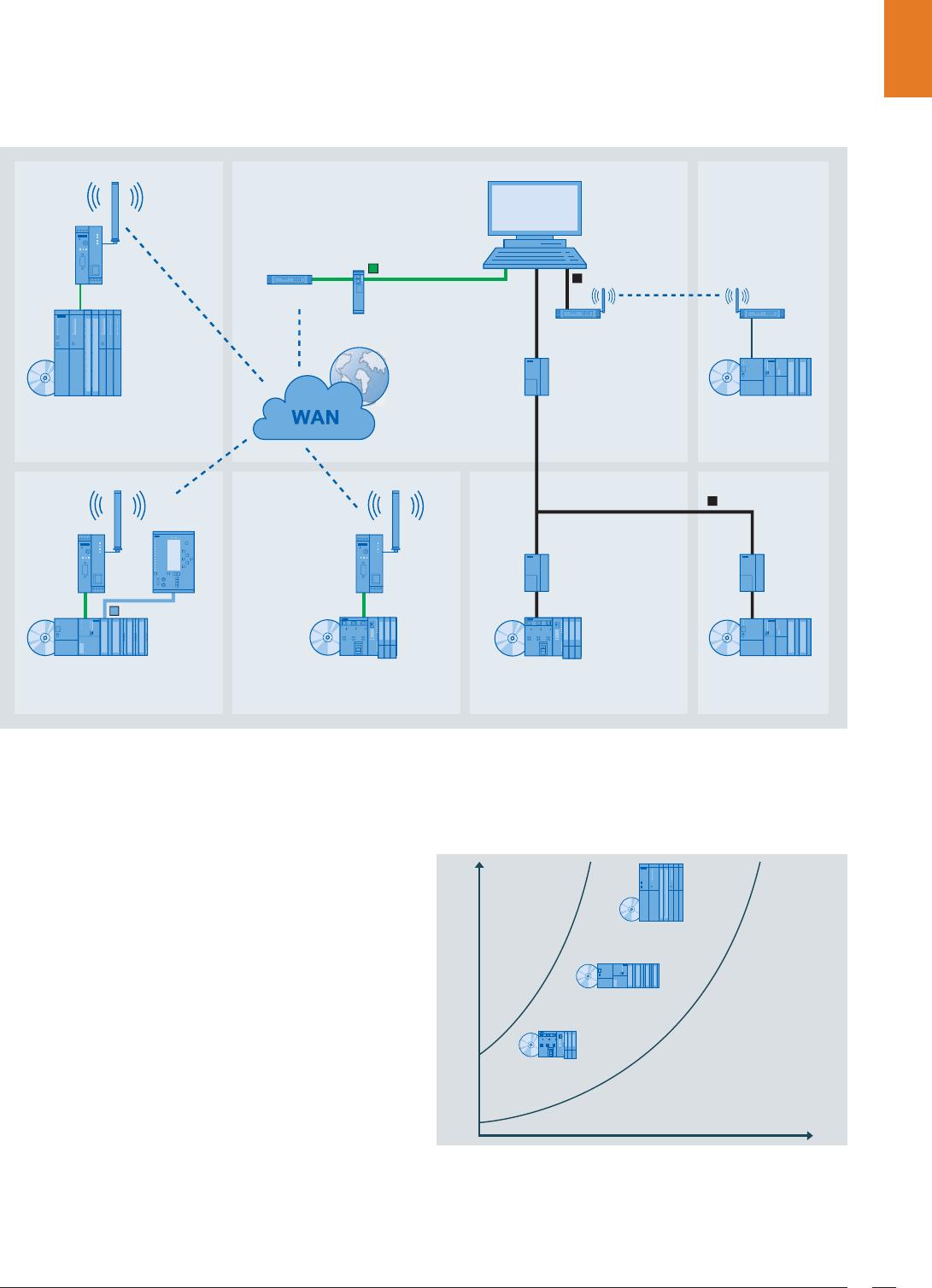
Flexible communication options in the WAN with IEC 870-5-101/IEC 870-5-104 telecommunication protocols
A telecontrol center which is seamlessly integrated into the
SIMATIC PCS 7 process control system by means of SIMATIC
PCS 7 TeleControl can control and monitor geographically dis-
persed outstations via serial (IEC 870-5-101 telecontrol proto-
col) or Ethernet TCP/IP (IEC 870-5-104 telecontrol protocol)
communication links.
SIMATIC S7 controllers (SIMATIC ET 200S with integral CPU,
SIMATIC S7-300/S7-300F, and SIMATIC S7-400/S7-400F/
S7-400H/S7-400FH) as well as third-party RTUs can be used as
outstations in this context. The control center is the master
during communication with the outstations.
The IEC 870-5-101 and IEC 870-5-104 telecontrol protocols
are anchored in the telecommunication product range
SIPLUS RIC. Based on specific libraries for telecontrol proto-
cols, SIPLUS RIC comprises low-cost bundles for outstations
which are based on SIMATIC ET 200S with integral CPU,
SIMATIC S7-300 or SIMATIC S7-400.
The performance of the telecontrol stations can be scaled
with SIPLUS RIC bundles configured as slaves for the tele-
control link as shown below:
Scalable performance of SIPLUS RIC bundles
IEC 60870-5-103
SINAUT
MD741-1
SINAUT
MD741-1
IEC 60870-5-101
SINAUT
MD2
G_PCS7_XX_00217
SINAUT
MD2
SINAUT
MD2
IEC 60870-5-101
IEC 60870-5-104
SINAUT
MD741-1
SIPROTEC
7SJ63
SIPLUS RIC Bundle
with SIMATIC S7-400
DSL router
SIPLUS RIC Bundle
with SIMATIC S7-300
SIPLUS RIC Bundle
with SIMATIC ET 200S
SIPLUS RIC Bundle
with SIMATIC ET 200S
SIPLUS RIC Bundle
with SIMATIC S7-300
SIPLUS RIC Bundle
with SIMATIC S7-300
Control center
Radio
network
SCALANCE S612,
security module
SIPLUS RIC Bundle
with SIMATIC S7-400
SIPLUS RIC Bundle
with SIMATIC S7-300
SIPLUS RIC Bundle with
SIMATIC ET 200S
Parameterization of SIMATIC STEP 7
Performance
Data volume
© Siemens AG 2011
IEC 870-5-101/IEC 870-5-104 telecontrol protocol24
The SIPLUS RIC bundles usually comprise:
•CPU
• Interface/communication module (if necessary)
•Memory card
• CD with library and registration code.
SIPLUS RIC products require additional material to establish
telecommunication links, e.g. TCP/IP converters – serial,
dedicated line modems, media converters, TCP/IP routers,
SCALANCE S612 and S613 security modules, switches, cables
etc.
In order to implement telecontrol networks, basic topologies
including point-to-point, multi-point, star and ring can be con-
figured using classic or TCP/IP-based media. These can be
combined flexibly independent from existing infrastructure.
Classic WAN media
(IEC 870-5-101 telecontrol protocol)
• Dedicated line via modem, e.g. SINAUT MD2
• Dedicated line over fiber-optic cables
• Private wireless networks
TCP/IP-based WAN media
(IEC 870-5-104 telecontrol protocol)
• Ethernet networks, e.g. SCALANCE X with fiber-optic
cables
• Industrial Wireless LAN with SCALANCE W
• Public networks and the Internet using DSL and/or GPRS
• Satellite communication, e.g. with Inmarsat
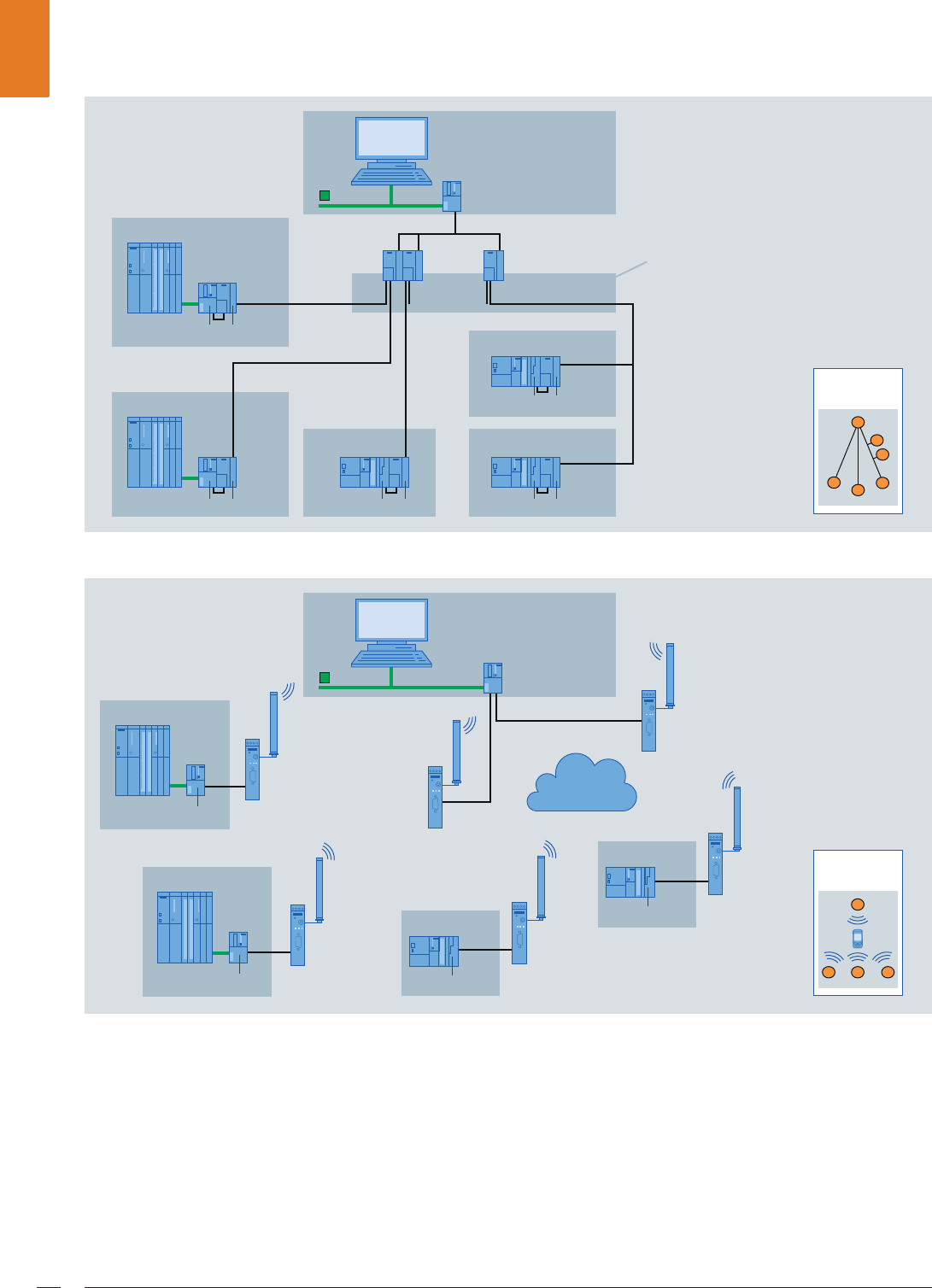
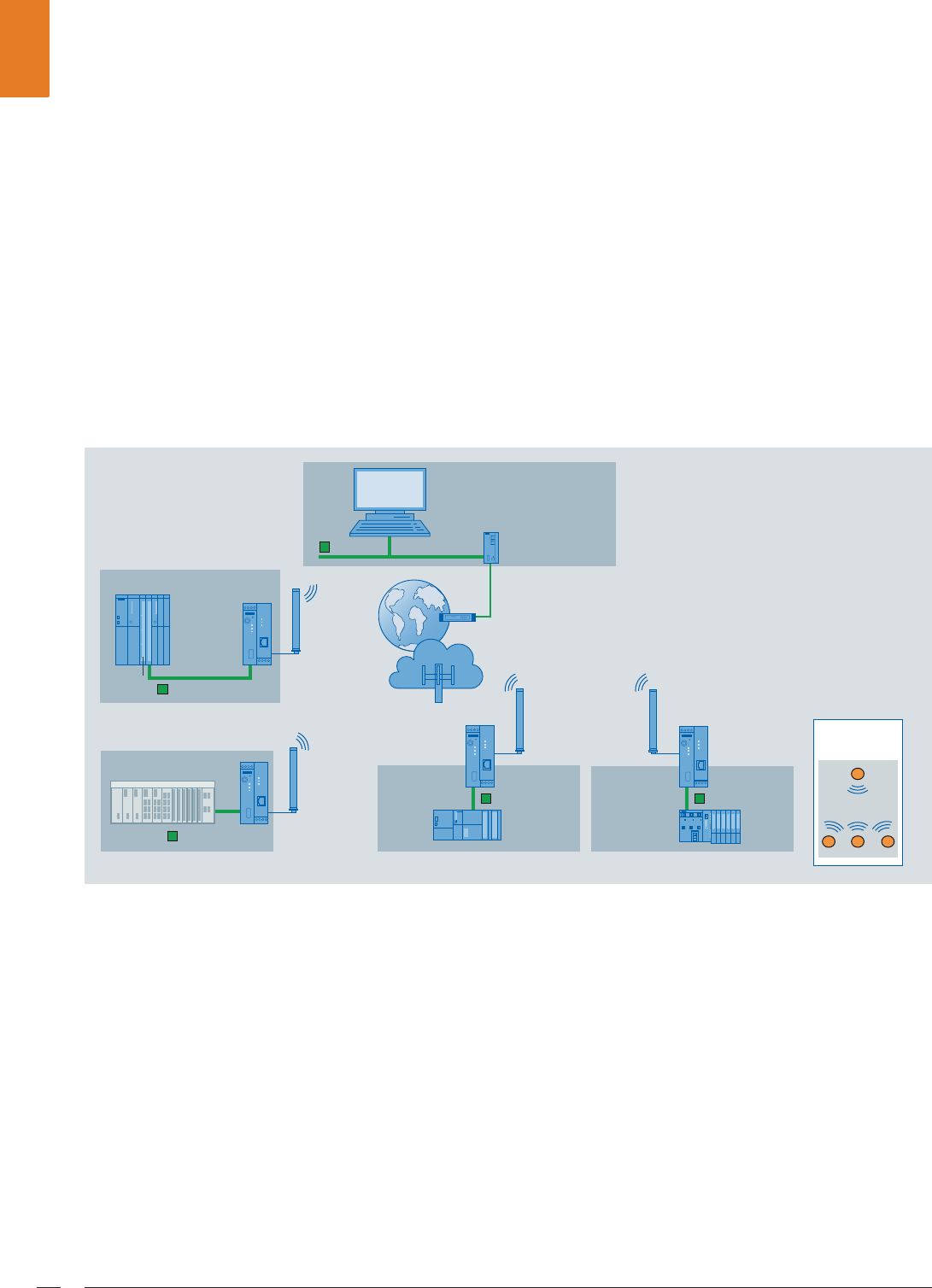
IEC 870-5-104 - example of TCP/IP-based WAN with GPRS radio network (star topology)
SCALANCE
S613
IEC 870-5-104
Ethernet
IEC 870-5-104
IEC 870-5-104
IEC 870-5-104 IEC 870-5-104
RTU S7-400
CP 443
MD741
MD741 MD741
G_PCS7_XX_00270
Third-Party RTU
Control center
SIMATIC PCS 7 TeleControl
Internet
Star via
wireless
DSL router
RTU S7-300
with CP 343
RTU ET 200S
with IM 151-8
PN/DP CPU
GPRS
radio network
© Siemens AG 2011
IEC 870-5-101/IEC 870-5-104 telecontrol protocol 25
IEC 870-5-104 - example of complex TCP/IP-based WAN with cable and GPRS networks
It is also possible to connect an outstation via two transmis-
sion paths to the control center in the SIMATIC PCS7 process
control system to achieve redundant data transmission.
Redundant transmission paths can be based on the same
or different communication protocols.
IEC 870-5-101/104 - example of redundant telecommunication links (IEC 870-5-101 representation without modems)
SCALANCE
S613
IEC 870-5-104
Ethernet
IEC 870-5-104
IEC 870-5-104
IEC 870-5-104
MD741
MD741
G_PCS7_XX_00271
Third-Party RTU
Control center
SIMATIC PCS 7 TeleControl
Internet
GPRS radio
network
DSL router
RTU S7-300
with CP 343
RTU ET 200S
with IM 151-8
PN/DP CPU
Complex network structure,
combination of different
topologies and media
RTU S7-400 with
CP 443
RTU S7-300 with
CP 343
RTU ET 200S
with IM 151-8
PN/DP CPU
IEC 870-5-104
G_PCS7_XX_00272
IEC 870-5-101IEC 870-5-104
Control center
SIMATIC PCS 7 client
PCS 7 TeleControl
OS server,
redundant
RTU S7-300
with 2 x CP 343
RTU S7-300
with CP 343 (left)
and CP 341
RTU ET 200S
with IM 151-8 PN/DP CPU
and 1 SI interface module
RTU S7-400 with
2 x CP 443
RTU S7-400 with CP 443
(left) and CP 441
Path
redundancy,
1 medium
Redundant system bus
Terminal bus (Ethernet)
TCP/IP to serial
converter
© Siemens AG 2011
Modbus telecontrol protocol26
Modbus telecontrol protocol
The Modbus telecommunication protocol is suitable for the
integration of existing units with a Modbus infrastructure into
the SIMATIC PCS 7 process control system.
Telecontrol communication for control and monitoring of
widely distributed outstations (RTUs) from a control center in
SIMATIC PCS 7 is possible with this protocol via both serial and
TCP/IP communication links.
The control center, represented by the SIMATIC PCS 7 Operator
System with SIMATIC PCS 7 TeleControl, is the Modbus master.
SIMATIC S7 controllers (SIMATIC ET 200S with integral CPU,
SIMATIC S7-300/S7-300F, and SIMATIC S7-400/S7-400F) as
well as third-party RTUs with a suitable Modbus interface can
be used as outstations (Modbus slaves).
The SIPLUS RIC range includes low-cost bundles for out-
stations with Modbus telecontrol protocol (serial or TCP/IP),
based on SIMATIC ET 200S with integral CPU and SIMATIC
S7-300. These usually comprise:
•CPU
• Interface/communication module (if necessary)
•Memory card
• CD with library and registration code.
In addition, further material is required to establish
the telecommunication links, e.g. TCP/IP converters – serial,
dedicated line modems, media converters, TCP/IP routers,
switches, cables etc.
The Modbus telecontrol protocol can be used to implement
telecontrol networks based on point-to-point and multi-point
topologies, both serial and TCP/IP. The following media can be
used for this:
Classic WAN media
• Dedicated line via modem, e.g. SINAUT MD2
• Dedicated line over fiber-optic cables
• Private wireless networks
TCP/IP-based WAN media
• Ethernet networks, e.g. SCALANCE X with fiber-optic
cables
• Industrial Wireless LAN with SCALANCE W
• Public networks and the Internet using DSL and/or GPRS
To permit redundant data transmission, outstations can be
connected to the control center in the SIMATIC PCS 7 process
control system over two paths. Two operating modes are
available:
• Load sharing: parallel utilization of both paths
• Master/standby: only one path is active, the other is passive
Modbus - example of serial and TCP/IP telecontrol connections (multi-point/point-to-point topologies)
SINAUT
MD2
SCALANCE
X101-1LD
SCALANCE
X101-1LD
SINAUT
MD2
SINAUT
MD2
G_PCS7_XX_00273
Control center
Modbus master
SIMATIC S7-400 with
CP 443 and software library
(Modbus slave)
SIPLUS RIC bundle
with SIMATIC ET 200S
(Modbus slave)
SIPLUS RIC bundle
with SIMATIC S7-300
(Modbus slave)
Point-to-
point
Multi-point
TCP/IP to serial converter
Fiber-optic cable
TCP/IP WAN router
© Siemens AG 2011

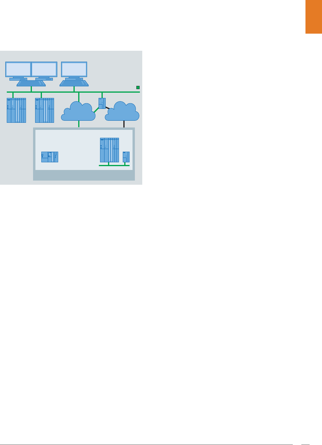
Redundancy 27
Redundancy
Increasing the plant availability
For the individual telecontrol protocols, reference was already
made as to how the availability of telecontrol communication
can be increased using redundant transmission paths. How-
ever, as a result of seamless integration of the telecontrol
technology into the SIMATIC PCS 7 process control system, the
redundant design of the telecontrol communication is embed-
ded in the redundancy concept of the complete system and
must therefore be considered globally.
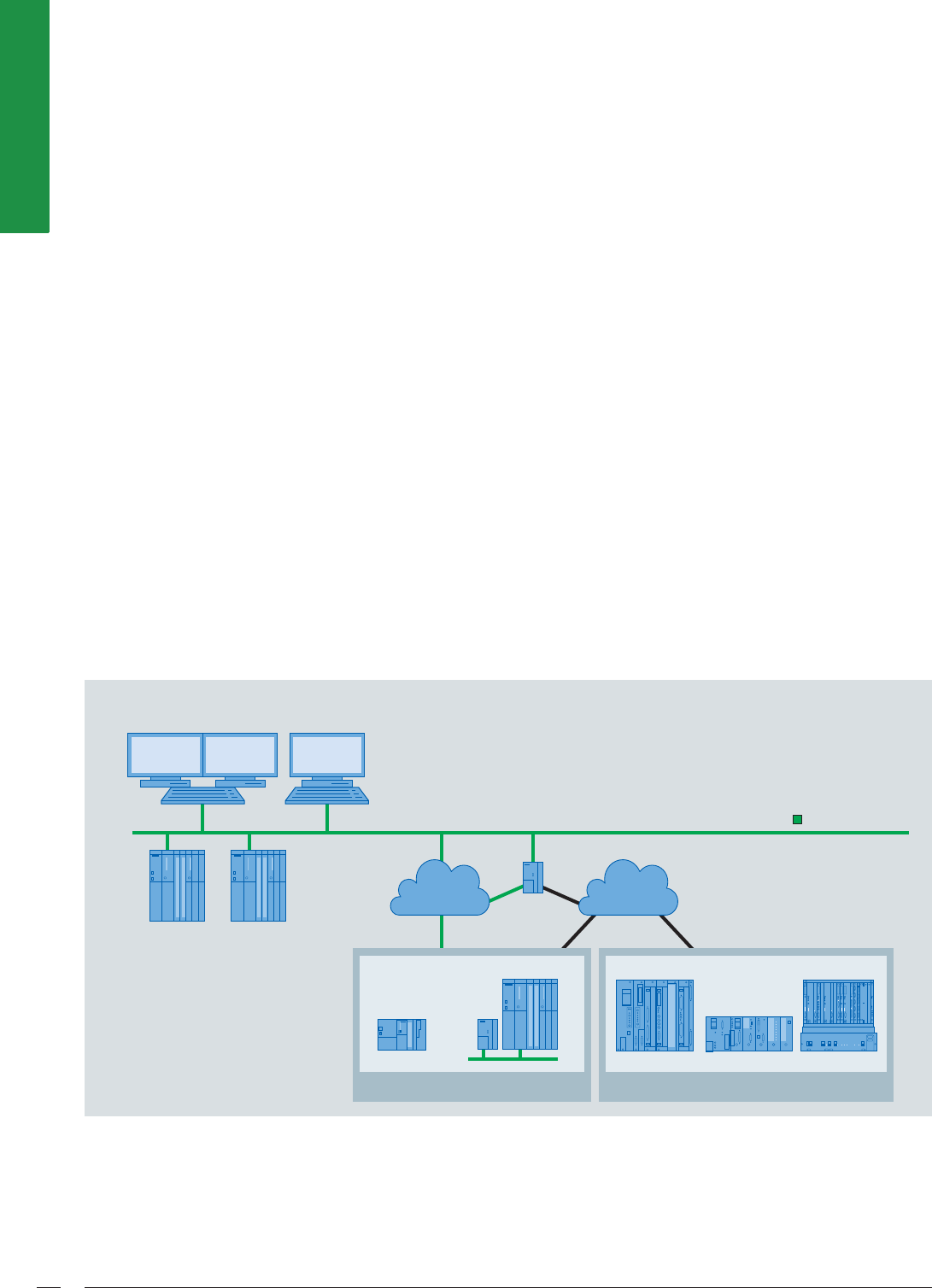
The example of a SIMATIC PCS 7 process control system
with integral telecontrol linking of RTUs on the basis of
the IEC 870-5-101/IEC 870-5-104 protocols demonstrates the
various possibilities for increasing plant availability:
• Redundant SIMATIC PCS 7 TeleControl OS servers for pro-
cess control of central and widely distributed units and for
archiving
• Redundant system bus for system communication
• Redundant telecontrol communication between control
center and RTUs over two separate transmission paths
• Redundant RTUs on the basis of S7-400H/ S7-400FH con-
trollers for local automation of remote units
• Redundant PROFIBUS for communication between control-
ler and process I/O (I/O modules, process instruments and
devices in the field)
• Redundant process I/O
It is also possible to implement safety-related functions in
the RTU (up to SIL 3) based on the S7-400FH controller and
F modules in the ET 200M remote I/O station.
Redundant telecontrol configuration based on the
IEC 870-5-101/IEC 870-5-104 protocols
G_PCS7_XX_00274
SIMATIC PCS 7
OS clients
Control center
SIMATIC PCS 7
TeleControl OS
with redundant
servers
Redundant system bus
Terminal bus
IEC 870-5-101
redundant
IEC 870-5-104
redundant
TCP/IP to serial
converter
RTU S7-400H
RTU
S7-400H
with CP 443
TCP/IP
WAN router
ET 200M
redundant
ET 200M redundant
with 2 x CP 341
© Siemens AG 2011
Migration28
Migration
Migration of existing telecontrol systems
Units with Modbus communication
The Modbus is widely used in automation plants due to its
straightforwardness and openness. The Modbus telecontrol
protocol can be used to implement both serial and TCP/IP com-
munication links between a control center in SIMATIC PCS 7
and RTUs with a corresponding Modbus interface.
In this manner, existing units with a Modbus infrastructure
can be integrated at low cost into the SIMATIC PCS 7 process
control system. The RTUs of these units can be SIMATIC S7
controllers (SIMATIC ET 200S with integral CPU, SIMATIC
S7-300/S7-300F and SIMATIC S7-400/S7-400F) as well as
third-party RTUs. Whereas RTUs with Modbus TCP/IP interface
can be integrated directly, serial third-party RTUs require spe-
cific interface converters for telecontrol communication.
Engineering data of third-party RTUs can be imported in CSV
format into the PCS 7 TeleControl engineering (DBA). The sta-
tus of the RTUs and the transmission paths is evaluated by the
"Diagnostics Modbus RTU" block and displayed in the control
center.
SINAUT ST1 stations based on SIMATIC S5
During the migration of existing systems, it is possible to inte-
grate outstations based on SIMATIC S5 into the SIMATIC PCS 7
process control system using SIMATIC PCS 7 TeleControl. In
the process, the ST1 telecontrol protocol is converted into the
ST7 protocol in the central TIM communication module.
Third-party stations
In addition to the Modbus telecontrol protocol, the DNP3
(serial and TCP/IP), IEC 870-5-101 (serial) and IEC 870-5-104
(TCP/IP) telecontrol protocols basically also support the con-
trol center linking of third-party RTUs when migrating existing
systems. The implementation depends on whether the third-
party RTU masters the corresponding protocol and whether
the interface converters are available if necessary.
Integration of SINAUT ST1 stations into telecontrol communication
Industrial Ethernet
TIM
4R-IE
S7-300
G_PCS7_XX_00180
S7-400 S5-115 S5-135/155
S5-100
IP-based
WAN
Classic
WAN
SINAUT ST7 stations SINAUT ST1 stations
6,0$7,&3&6ZLWK6,0$7,&3&67HOH&RQWURO
© Siemens AG 2011
Migration 29
Integration of existing SINAUT LSX systems per PCS 7 TeleControl S7 EDC driver
Integration of third-party stations with OPC
Along with additive engineering performance on the basis of
DBA technology, SIMATIC PCS 7 TeleControl also allows inte-
gration of third-party RTUs for which an OPC server exists into
the process control with the SIMATIC PCS 7 Operator System.
SIMATIC PCS 7 TeleControl then supports data exchange
between the operator system (OPC client) and the RTU
(OPC server) per OPC DA.
SINAUT LSX systems
Existing SINAUT LSX systems can also be migrated with
SIMATIC PCS 7 TeleControl. The SIMATIC S7 controllers with
EDC communication protocol (Event Driven Communication)
installed in the SINAUT LSX systems are then integrated into
SIMATIC PCS 7 TeleControl per PCS 7 TeleControl S7 EDC
driver. Because the SINAUT LSX system can coexist at all levels
next to the new system architecture as long as necessary,
modernization is possible step-by-step and without short-
lived intermediate solutions.
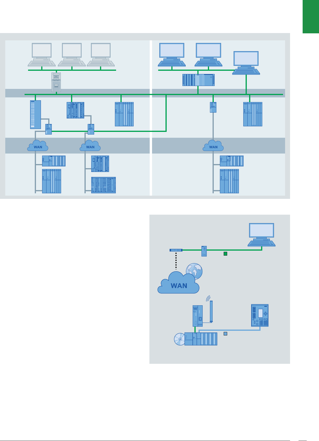
Linking of SIPROTEC or third-party protection equipment
The protocol expansion IEC 870-5-103 Master for SIPLUS RIC
bundles also allows interfacing of SIPROTEC or third-party pro-
tective equipment via SIMATIC PCS 7 TeleControl. The RTU
(ET 200S with CPU, S7-300 or S7-400 controller) then serves
as a converter between the IEC 870-5-103 protection data
protocol and the IEC 870-5-101 or IEC 870-5-104 protocol.
Example of interfacing of SIPROTEC protective equipment
Compared to PROFIBUS DP interfacing of the protective equip-
ment, this configuration provides the following advantages:
• Greater distances are possible.
• The highly exact time stamps are transferred from the pro-
tective equipment to the control system.
SIMATIC
PCS 7
S7-400
S7-400
S7-300
S7-400
S7-300
G_PCS7_XX_00275
S5-115
S5-135
S7
(EDC)
S5 / ST1
(KOMSYS)
HMI
PCS 7
TeleControl
OS server
PCS 7
Engineering
System
(DBA)
Master
TIM (ST7)
Node
station
TIM
PCS 7 clientsSINAUT LSX
clients
SINAUT LSX
server (ST7)
ST1 RTUs ST7 RTUs
SIMATIC PCS 7 TeleControlSINAUT LSX
LAN
AS
WAN
RTU
FEP
Front End
Processor
IEC 60870-5-104
IEC 60870-5-103
SIPROTEC
7SJ63
G_PCS7_XX_00276
SINAUT
MD741-1
SCALANCE
S612
Control center
SIPLUS RIC bundle
with SIMATIC S7-300
DSL router
© Siemens AG 2011
Application examples30
Application examples
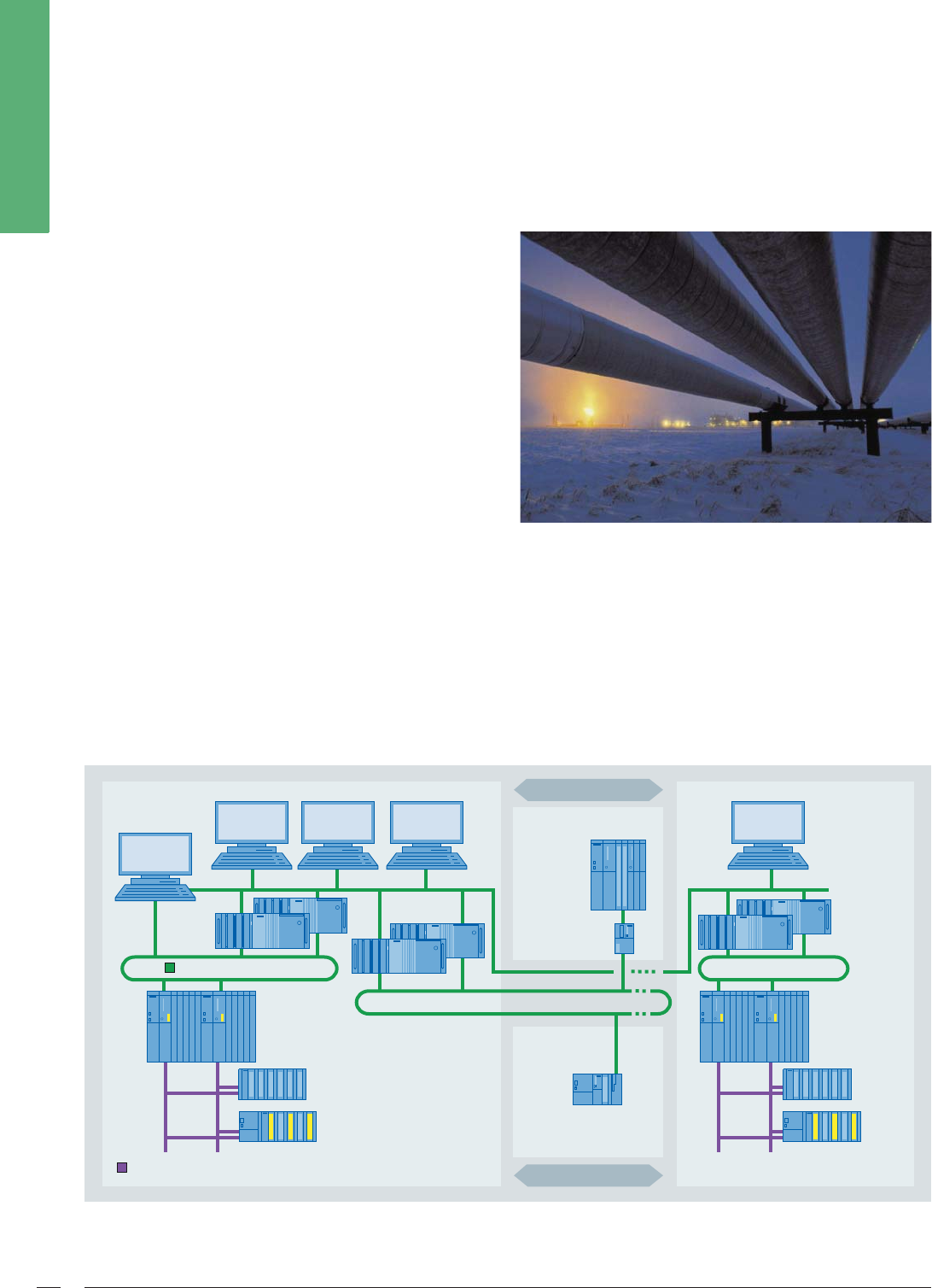
Automation of a gas pipeline with block valve and metering stations
Uniform automation of all stations in the gas network
■SIMATIC PCS 7 process control system for compressor
and pressure reducing stations
■SIMATIC PCS 7 TeleControl with SINAUT telecontrol tech-
nology on the basis of S7-300/S7-400 controllers for
block valve and metering stations
■Combination of process control at one operator station
(SIMATIC PCS 7 OS client)
■Compliant process control with uniform faceplates,
alarms, trends etc.
High system availability resulting from redundancy
■Redundant pair of SIMATIC PCS 7 OS servers
■Redundant pair of SIMATIC PCS 7 TeleControl OS servers
■Ring topology with redundant media Integral safety technology for emergency shutdown (ESD)
ESD is integrated homogenously into the automation plant
(compressor and relief stations):
• Redundant safety-related controllers
• Redundant PROFIBUS with PROFIsafe
• ET 200M with F modules
System architecture of gas pipeline automation with SIMATIC PCS 7 TeleControl
Industrial Ethernet
PROFIBUS
SINAUT TIM
Pipeline
Pipeline
Compressor station
Metering stations
Local station
Block valve stations
Pressure reducing station
SIMATIC PCS 7 clients
G_PCS7_XX_00277
SIMATIC PCS 7
Engineering
Station
SIMATIC PCS 7
client
RTU S7-300 incl.
SINAUT TIM
SIMATIC
PCS 7 server
(redundant)
SIMATIC PCS 7
FH controller
PCS 7 TeleControl
OS server
(redundant)
SIMATIC PCS 7
FH controller
S7-400
controller
approx. 800 I/Os
approx.
100 I/Os
approx. 30 I/Os
approx.
300 I/Os
Safety ESD
Safety
ESD
© Siemens AG 2011
Application examples 31
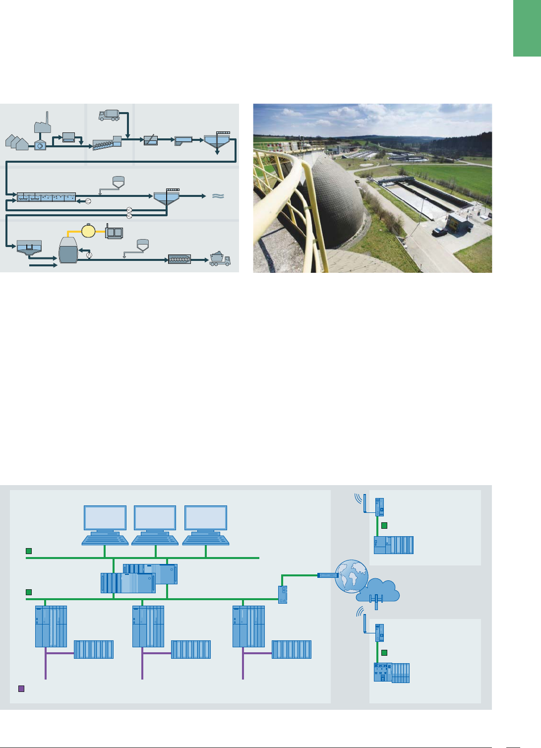
Automation of a sewage treatment plant
with pumping station and stormwater overflow tank
Symbolic technical representation of a sewage treatment plant
Uniform control of the complete wastewater network
• SIMATIC PCS 7 process control system in the sewage treat-
ment plant
• SIMATIC PCS 7 TeleControl with SIPLUS RIC telecontrol tech-
nology on the basis of the IEC 870-5-104 protocol
• Combination of process control at one operator station
(PCS 7 OS client)
• Compliant process control with uniform faceplates, alarms,
trends etc.
Cost-effective RTUs exactly matched to the respective unit
• S7-300 controller for pumping station
• ET 200S with integral CPU for stormwater overflow tank
Secure communications
• Protection of telecontrol network by SCALANCE S613
industrial security module
• Application of GPRS technology
Reporting and archiving in compliance with
ATV-DVWK M 260
With application of the SIMATIC PCS 7 add-on product ACRON
System architecture of sewage treatment plant automation with SIMATIC PCS 7 TeleControl
Municipal sewerage
system Mechanical
purification
Biological
purification
Sludge treatment
Industry
Private
households
Stormwater
overflow tank
Dosing of precipitant
Pumping
station
Lifting
equipment
Screen
Drainage
Aeration
Gasometer Sludge
dewatering
Sludge output
Combined heat
and power plant
Preliminary sedimentation
Preliminary sedimentation
Pre-
thickening Digestion tank Dosing of flocculent
Final clarification
Sand and
grease trap Digestion tank
Delivery of
fecal matter
Industrial Ethernet
IEC 870-5-104
IEC 870-5-104
Industrial Ethernet
PROFIBUS
MD741
MD741
G_PCS7_XX_00278
IEC 870-5-104
GPRS
SIMATIC PCS 7 OS clients
SIMATIC PCS 7
controller
PCS 7 TeleControl OS
server (redundant)
PROFIBUS I/O
approx. 500 I/Os
Inflow
pre-treatment
SIMATIC PCS 7
controller
PROFIBUS I/O
approx. 500 I/Os
Aeration blowing
station
SIMATIC PCS 7
controller
PROFIBUS I/O
approx. 500 I/Os
Sludge
treatment
Local
station
Local
station
Sewage plant
Pumping station
Stormwater overflow tank
DSL router
SCALANCE
S613
ET 200S
with IM 151-8 CPU
approx. 25 I/Os
S7-300
approx. 150 I/Os
Internet
© Siemens AG 2011

The information provided in this brochure contains descriptions
or characteristics of performance which in case of actual use do
not always apply as described or which may change as a result of
further development of the products. The desired features are
only binding if explicitly agreed in the contract. Availability and
technical specifications are subject to change without notice.
Any product names mentioned may be trademarks or product
designations of Siemens AG or their suppliers, whose use by third
parties for their own purposes may infringe the rights of the
trademark owners.
Additional information
SIMATIC controllers:
www.siemens.com/simatic-controller
SIMATIC automation systems:
www.siemens.com/simatic
Totally Integrated Automation:
www.siemens.com/totally-integrated-automation
SIPLUS extreme – ruggedness and refinement:
www.siemens.com/siplus-extreme
Service and Support:
www.siemens.com/automation/service&support
SIMATIC contacts:
www.siemens.com/automation/partner
Information material to download:
www.siemens.com/simatic/printmaterial
SIMATIC Guide Manuals:
www.siemens.com/simatic-docu
Ordering on the Internet with the Industry Mall:
www.siemens.com/industrymall
Siemens AG
Industry Sector
Industrial Automation Systems
P.O. Box 4848
90026 NUREMBERG
GERMANY
Subject to change without prior notice
Order No.: E86060-A4678-A281-A1-7600
3P.8315.58.04 / Dispo 09508
BR 0111 3. ERD 32 En
Printed in Germany
© Siemens AG 2010
www.siemens.com/automation
© Siemens AG 2011
