Sierra Wireless ULC BX31A Radio Module User Manual AirPrime BX3100 BX3105 Wi Fi BT Module Hardware Integration Guide
Sierra Wireless Inc. Radio Module AirPrime BX3100 BX3105 Wi Fi BT Module Hardware Integration Guide
41112627 AirPrime BX3100-BX3105 Hardware Integration Guide r3
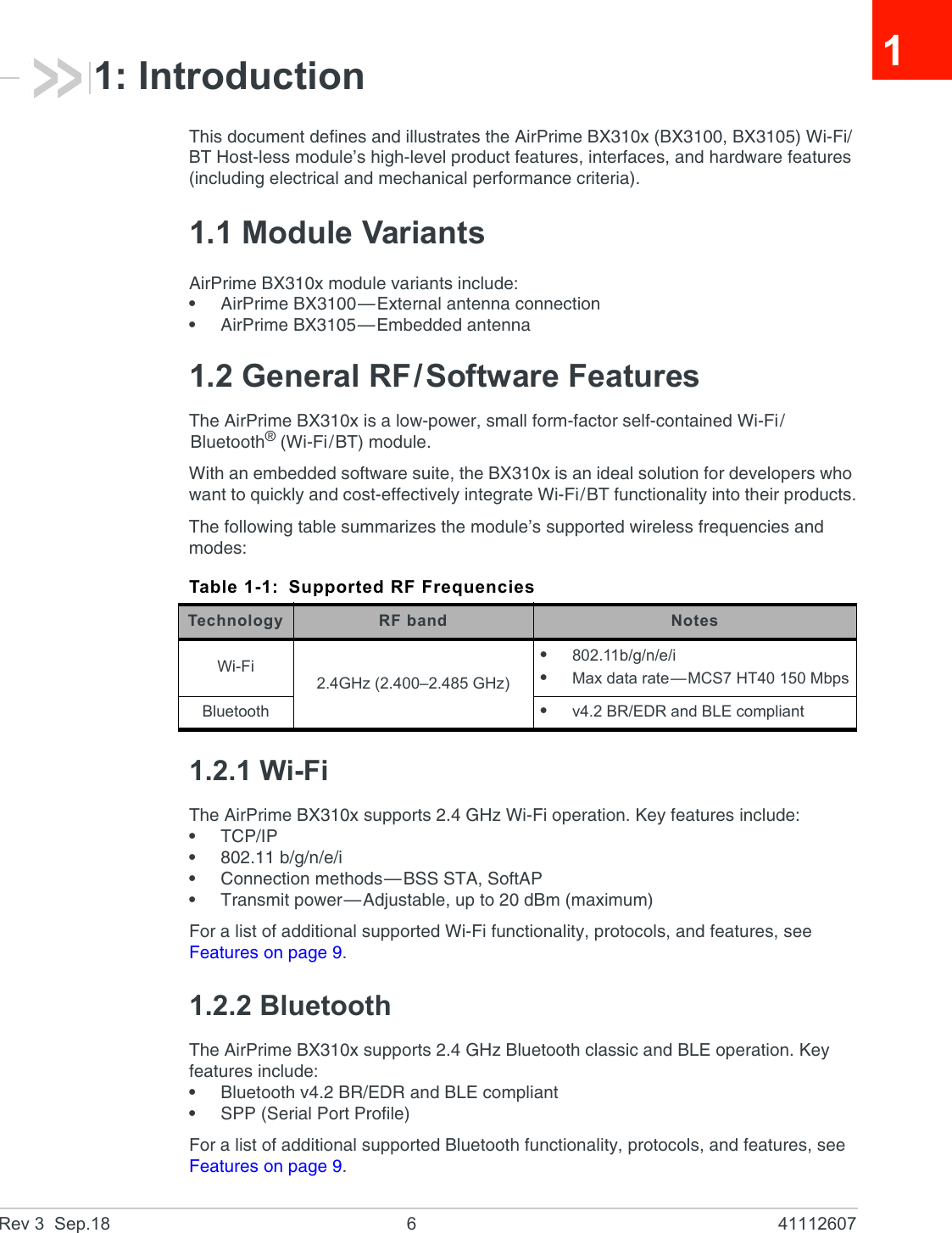
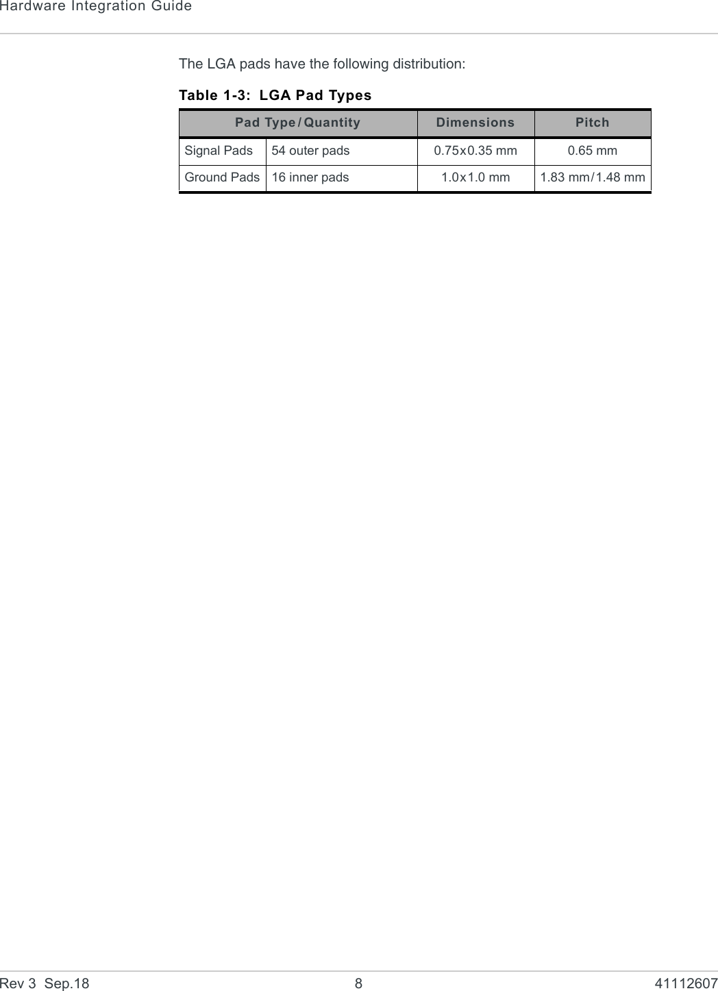
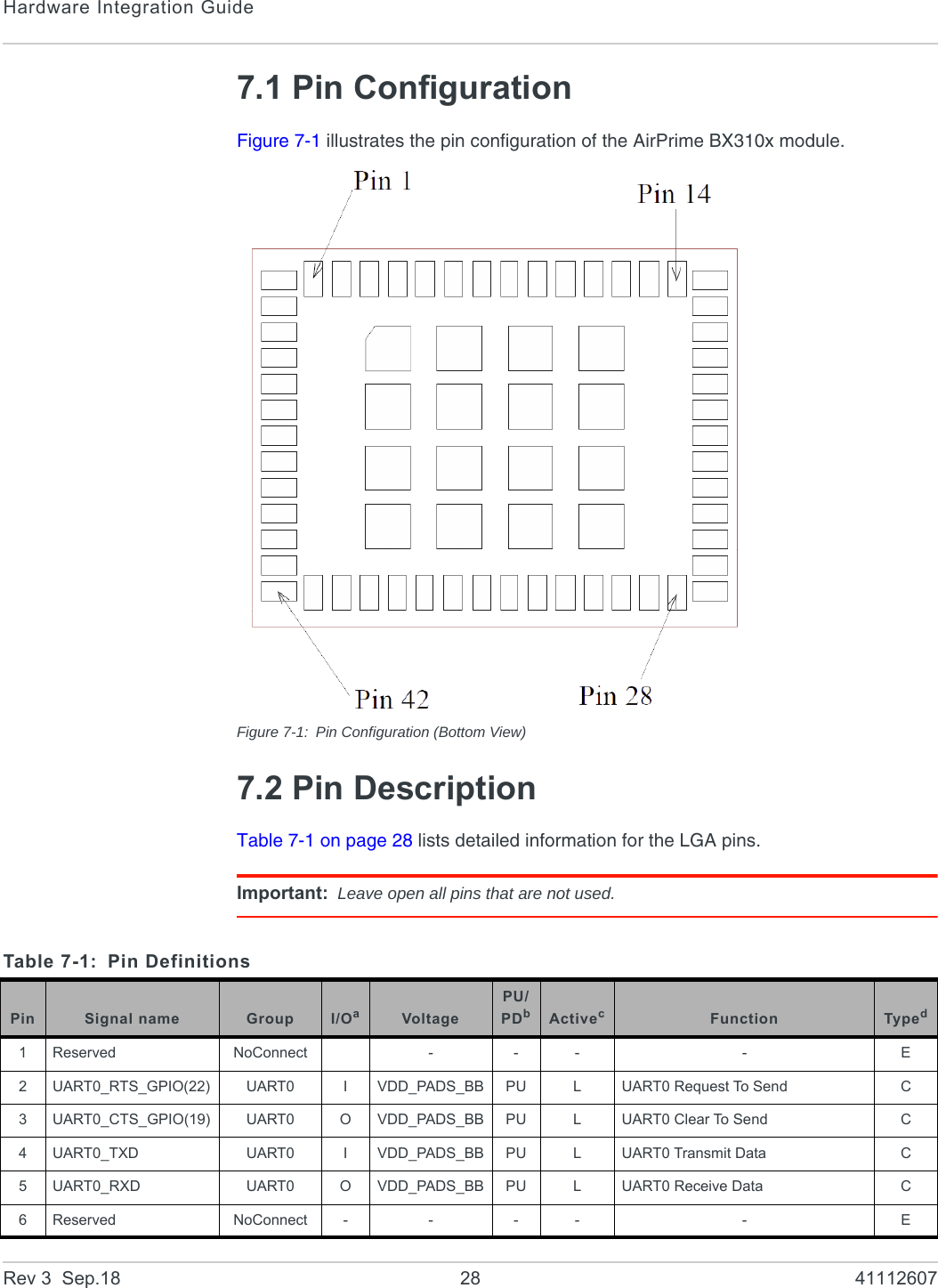
![IntroductionRev 3 Sep.18 7 411126071.2.3 InterfacesThe AirPrime BX310x provides the following interfaces and peripheral connectivity:•Power supply—See Power Supply Ratings on page 11.•RF—See RF on page 12.•UART serial link—See UART on page 15.•ADC/Voltage measurement—See ADC/Voltage Measurement on page 16.•I2C—See I2C Interface on page 17.•Digital audio (I2S)—See I2S Interface (Digital Audio) on page 18.•GPIOs—See General Purpose Input/Output (GPIO) on page 18.•SPI bus—See SPI Bus on page 20.•SDIO—See Secure Digital IO (SDIO) Interface on page 21.•Module enable—See Module Enable on page 22.•PWM—See PWM on page 22.1.2.4 Configuration UtilityThe AirPrime BX310x includes a browser-based utility for device configuration. For usage details, refer to [1] AirPrime BX310x AT Command Reference available at source.sierrawireless.com.1.3 General Hardware Features1.3.1 Physical Dimensions and Connection InterfaceAirPrime BX310x modules are compact, robust, fully shielded and laser-marked modules with the dimensions noted in Table 1-2.The AirPrime BX310x module is an LGA form factor device. All electrical and mechanical connections are made through the 70 Land Grid Array (LGA) pads on the bottom side of the PCB. (See Figure 7-1 on page 28 for details.)Table 1-2: AirPrime BX310x Dimensionsaa. Dimensions are accurate as of the release date of this document.ParameterNominalTolerance UnitsBX3100bb. BX3100 is a CF3 xSmall module, which belongs to the Common Flexible Form Factor (CF3) family of WWAN modulesBX3105Length 11.5 13.5 ±0.10 mmWidth 9.5 11.5 ±0.10 mmThickness 2.4 2.4 ±0.20 mmWeight 0.56 0.65 ±0.10 g](https://usermanual.wiki/Sierra-Wireless-ULC/BX31A/User-Guide-4001944-Page-7.png)
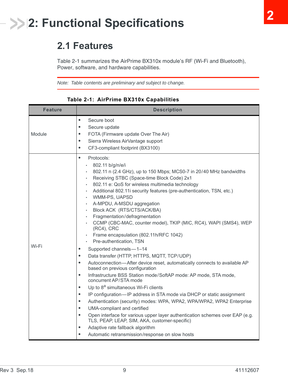
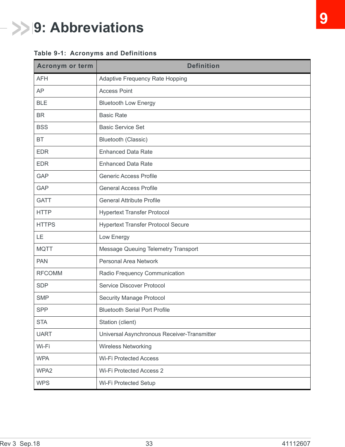
![Hardware Integration GuideRev 3 Sep.18 10 41112607Bluetooth•Bluetooth v4.2 BR/EDRb and BLE compliant•Supported channels: BT Classicb—0–78; BLE—0–39•Supported v4.2 modes: BRb (Basic Rate); EDRb (Enhanced Data Rate); LE (Low Energy)•BTb classic mandatory features•BT low-energy mandatory features•Class 1/Class 2/Class 3 transmitter without external power amplifier•Class 1 operation without external PA•Enhanced power control (>30 dB dynamic control range)•+10 dBm transmitting power•NZIF receiver with -98 dBm sensitivity•Modulation—p/4 DQPSKb, 8 DPSKb•ACLb, SCOb, eSCOb•Adaptive Frequency Hopping (AFH)•BT 4.2 controller and host stackb•Service Discover Protocol (SDP)b•General Access Profile (GAP)•Security Manage Protocol (SMP)b•Bluetooth Low Energy (BLE)•ATT/GATT•BLE Beaconb•SPPb, RFCOMM•Profiles: Wi-Fi Autoconnection—After device reset, automatically connects to available AP based on previous configuration.•UART features: GATT profiles, Define personal services•Roles—Simultaneous Central (access point)/Peripheral (client)•Simultaneous connections:·Up to 7a(total) simultaneous connections, including up to 3aBLE connec-tions·Simultaneous BT Classicb and BLE connections•PCMb/I2SbConfigurationDevice configuration methods:•Built-in web-based configuration utility. See Configuration Utility on page 7.•AT commands available over UART, Wi-Fi, and BT links. Refer to [1] AirPrime BX310x AT Command Reference at source.sierrawireless.com.Security•All standard IEEE802.11 security features, including WFA, WPA/WPA2, WAPI•Secure boot•Flash encryption•Cryptographic hardware acceleration: AES, HASH (SHA-2) library, RSA, ECC, Random Number Generator (RNG)Power managementMultiple power modesb to reduce power consumption: Active, Radio off, Light sleep, Deep sleep, HibernationSleep Patterns: Association sleep pattern, ULP sensor-monitored patternba. Subject to firmware support and RAM limitations.b. Support pending firmware upgrade.Table 2-1: AirPrime BX310x Capabilities (Continued)Feature Description](https://usermanual.wiki/Sierra-Wireless-ULC/BX31A/User-Guide-4001944-Page-10.png)
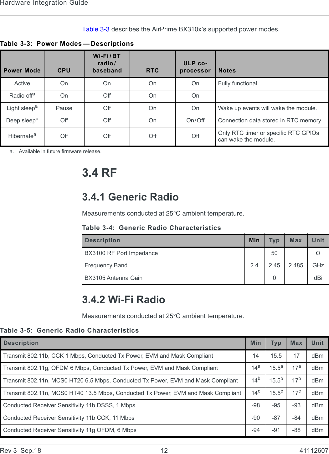
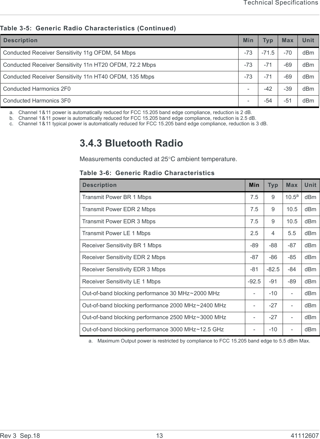
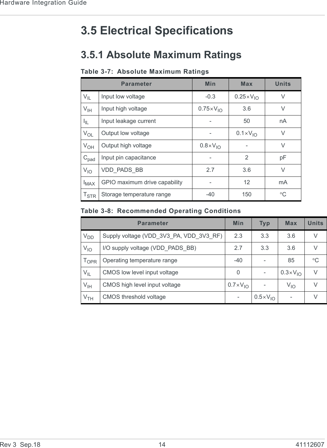
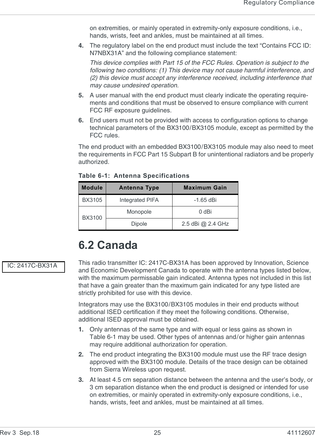
![Rev 3 Sep.18 11 4111260733: Technical Specifications3.1 EnvironmentalThe environmental specifications for operation and storage of the AirPrime BX310x are defined in Table 3-1.3.2 Power Supply RatingsDC power is supplied via the pins described in Table 3-2 on page 11.Note: Operation above the maximum specified operating voltage (see Table 3-8 on page 14) is not recommended, and specified typical performance or functional operation of the device is neither implied nor guaranteed.3.3 Power ManagementThe AirPrime BX310x switches between several power modes to minimize current consumption.Light Sleep and Deep Sleep modes are enabled via AT commands from the host. Refer to [1] AirPrime BX310x AT Command Reference for details.Table 3-1: Environmental SpecificationsParameter RangeAmbient Operating Temperature -40°C to +85°CAmbient Storage Temperature -40°C to +105°C(Recommended)Table 3-2: Power Supply PinsPin Name Voltage Direction Function33 VGPIO 3.3V Output Supply voltage reference for secondary I2C interface (pins 53/54)50 VDD_3V3_RF 2.3–3.6V Input RF/Analog signal power supply51 VDD_3V3_PA 2.3–3.6V Input Internal Power Amplifier power supply52 VDD_PADS_BB 2.7–3.6V Input Baseband/Digital I/O power supply](https://usermanual.wiki/Sierra-Wireless-ULC/BX31A/User-Guide-4001944-Page-11.png)
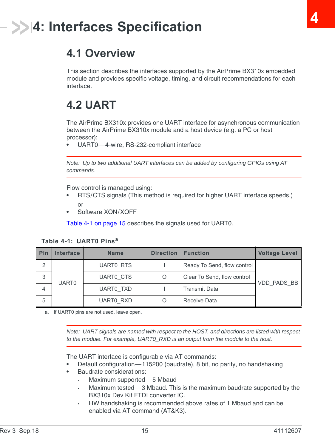
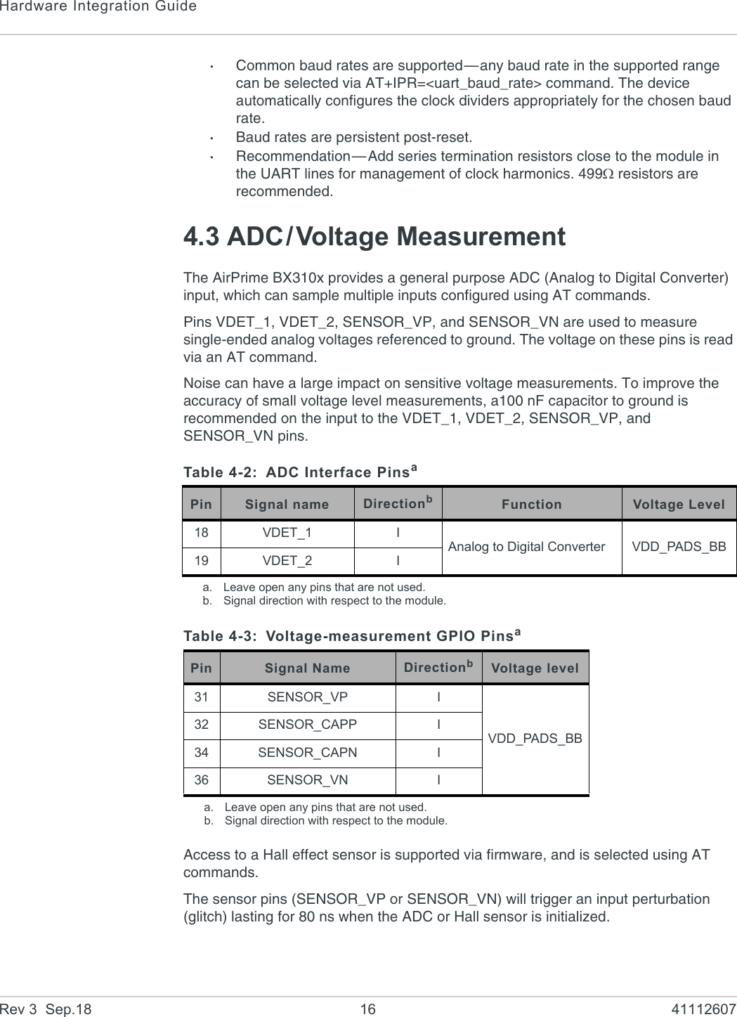
![Interfaces SpecificationRev 3 Sep.18 17 411126074.4 I2C InterfaceThe AirPrime BX310x module provides two I2C (Inter-Integrated Circuit) dedicated serial ports (bus interface) based on [2] The I2C Bus Specification, Version 2.1, January 2000 (Phillips Semiconductor document number 9398 393 40011).The interfaces use the pins indicated in Table 4-4.This implementation of the I2C interface includes the following characteristics:•Supported voltage:·Primary I2C (3.3 V, configurable)·Secondary I2C (3.3 V)•Standard-mode interface—Data transfer rates up to 100 kbit/s•Fast-mode interface—Data transfer rates up to 400 kbit/s)•Master mode operation•Addressing modes—7-bit; 10-bit; Dual addressing modeExternal 2.2 k pull-up resistors must be applied to I2C signals (see Figure 4-1 on page 17).For I2C bus details, including I2C bus waveform and timing details, refer to the I2C Bus Specification.4.4.1 ApplicationFigure 4-1: Example of I2C Bus ApplicationTable 4-4: I2C Interface Pinsaa. Leave open any pins that are not used.Pin Signal name Direction Function Voltage Level9I2C1_SCL I/O Primary I2C interfaceVDD_PADS_BB17 I2C1_SDA I/O Primary I2C interface53 I2C2_SDA I/O Secondary I2C interfaceVGPIO54 I2C2_SCL I/O Secondary I2C interfaceAirPrime BX310xWi-Fi/BT ModuleCustomerApplicationI2C1_SDAI2C1_SCL 2.2K 2.2KVDD_PADS_BBI2C2_SCLI2C2_SDA 2.2KVGPIO2.2K](https://usermanual.wiki/Sierra-Wireless-ULC/BX31A/User-Guide-4001944-Page-17.png)
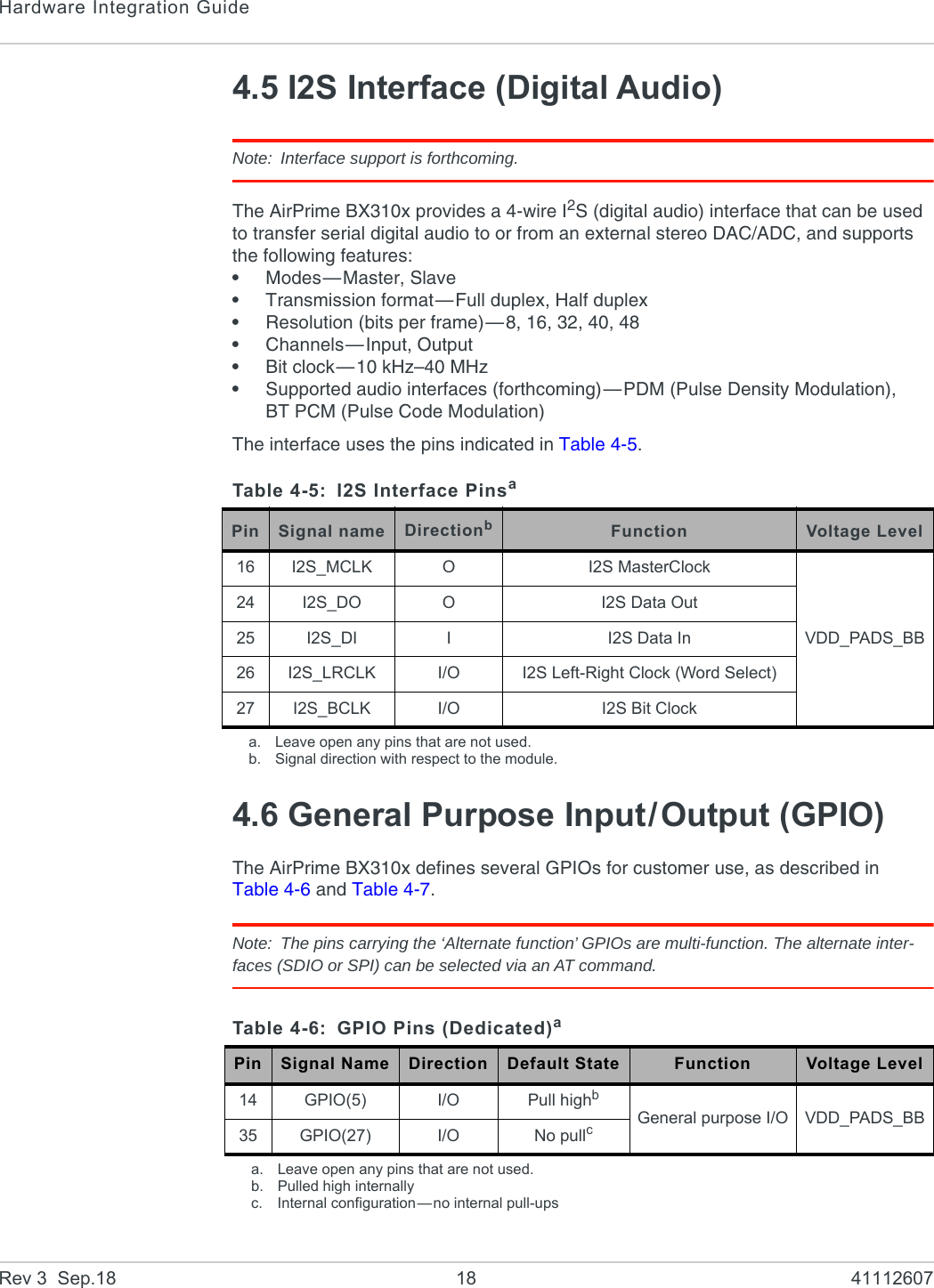
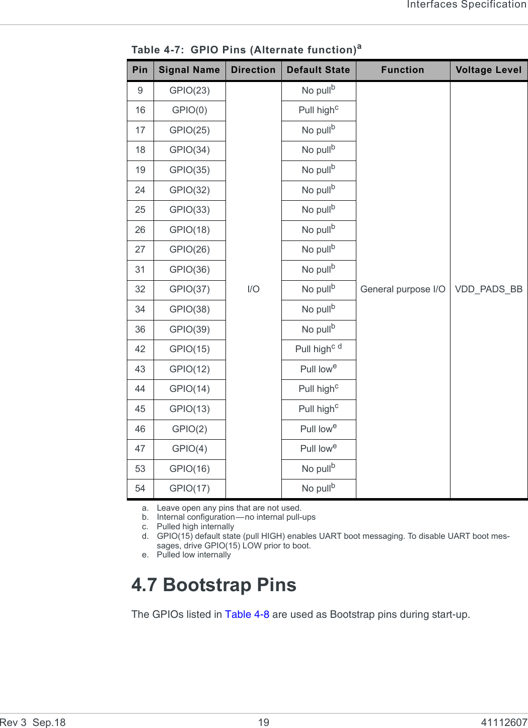
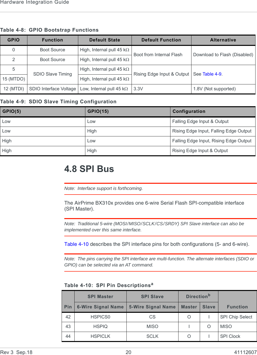
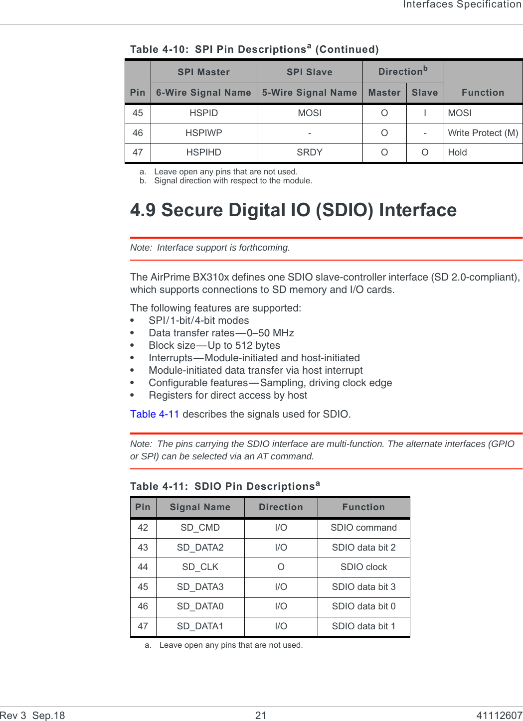
![Hardware Integration GuideRev 3 Sep.18 22 41112607SDIO is particularly susceptible to tracking impedance and length variations between the SDIO tracks. Ensure that controlled impedance tracking is used, and minimize tracking length between the module and SD slave device. Add series resistor footprints at the host end to decrease the drive current and reduce potential interference, and match the length of all the SD tracks to within 1 mm.SDIO tracking can cause significant radiated interference at integer multiples of the SD clock frequency, which can be picked up by the BX310x antenna. Bury SDIO tracks between ground planes and ensure stitching ground vias are placed throughout the board surrounding the SDIO tracking.SDIO timing during the boot process is provided by GPIO(5) and GPIO(15). See Table 4-9 on page 20 for details.4.10 Module EnableThe AirPrime BX310x uses the ENABLE (Module Enable) signal to turn the module on/off:•Turn module on—Drive ENABLE high (to VDD_PADS_BB)•Turn module off—Drive ENABLE low (to 0V)To avoid a possible implementation-dependent issue where enabling/disabling Wi-Fi functionality could cause a perturbation (glitch) on the power supply rails that impacts module operations, a short delay (1 ms recommended) is required for the power supply to stabilize before enabling the module.If ENABLE is controlled by the Host, the host implements the delay (from the time the supply is present) before driving ENABLE high.If ENABLE is hard-wired to the supply (VDD_PADS_BB), an RC circuit (10k & 0.1uF) is required. The RC circuit will create the required delay, allowing the supply to stabilize before ENABLE is pulled high.Do not leave this pin unconnected.4.11 PWMThe AirPrime BX310x supports the use of PWM functionality on GPIOs (GPIO(5) and GPIO(27)) via AT command configuration. Refer to [1] AirPrime BX310x AT Command Reference for details.Table 4-12: Enable Pin DescriptionPin Signal Name Directionaa. Signal direction with respect to the module.Function Voltage Level37bb. Do not leave this pin unconnected.ENABLE IStart/stop module VDD_PADS_BB](https://usermanual.wiki/Sierra-Wireless-ULC/BX31A/User-Guide-4001944-Page-22.png)
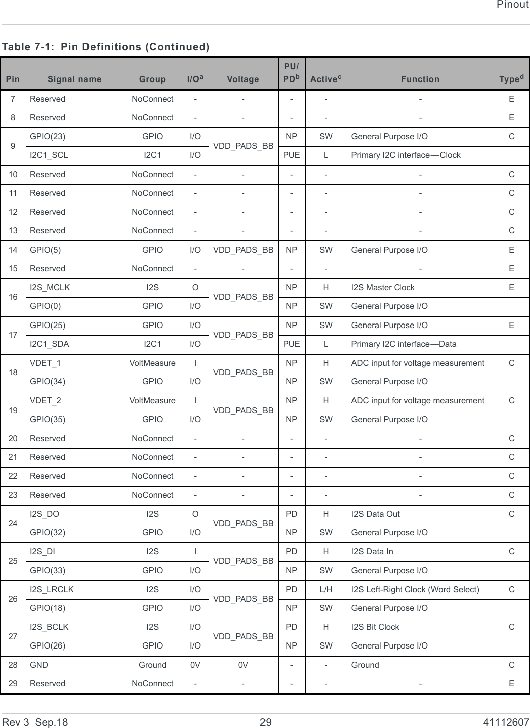
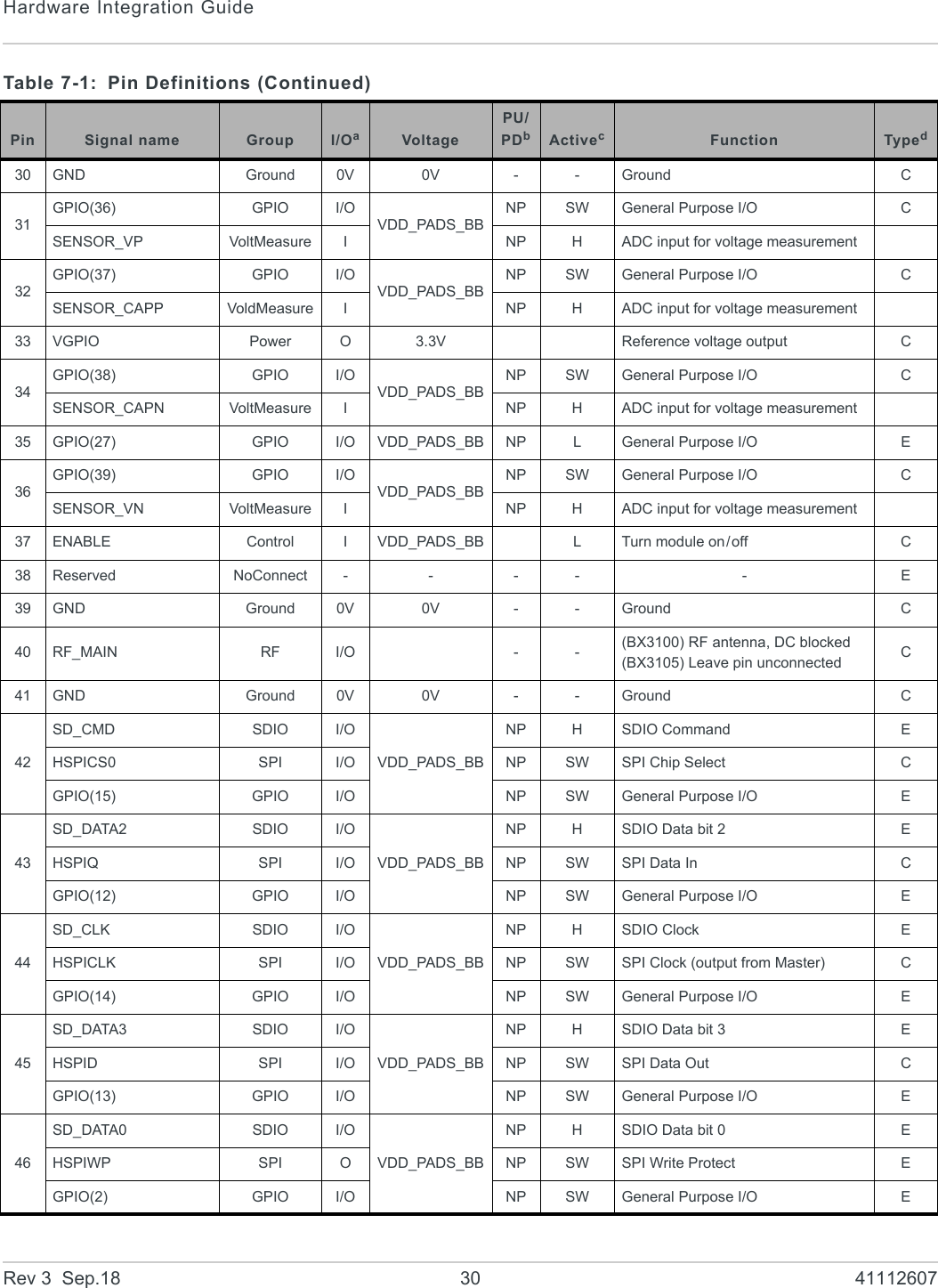
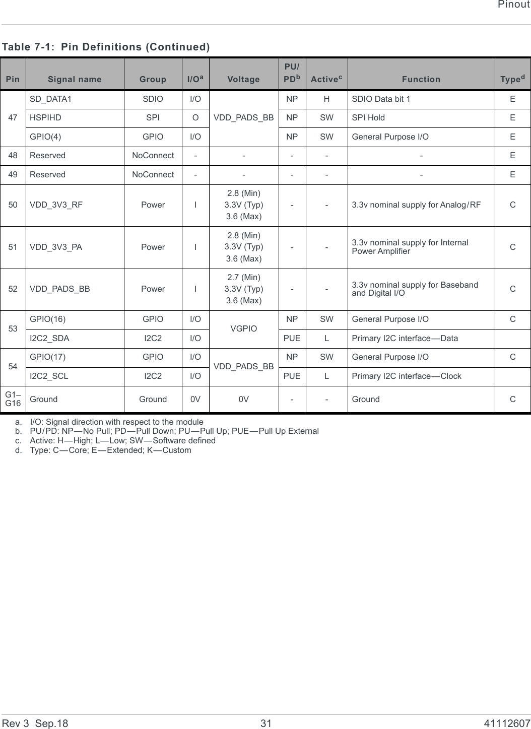
![Rev 3 Sep.18 32 4111260788: References8.1 Web Site SupportCheck http://source.sierrawireless.com for the latest documentation available for the AirPrime BX310x.8.2 Reference Documents[1] AirPrime BX310x AT Command ReferenceReference number: 41111445[2] The I2C Bus Specification, Version 2.1, January 2000 (Phillips Semiconductor document number 9398 393 40011)](https://usermanual.wiki/Sierra-Wireless-ULC/BX31A/User-Guide-4001944-Page-32.png)
