Sierra Wireless ULC MC8805 Radio Module User Manual TempConfidential 411xxxx AirPrime MC8805 Hardware Integration Guide v1 Draft B
Sierra Wireless Inc. Radio Module TempConfidential 411xxxx AirPrime MC8805 Hardware Integration Guide v1 Draft B
TempConfidential_411xxxx AirPrime MC8805 Hardware Integration Guide v1 - Draft B
![Rev 1 Dec.12 Proprietary and Confidential - Contents subject to change 711: IntroductionThe Sierra Wireless MC8805 PCI Express Mini Card is a compact, lightweight, wireless UMTS-based modem.The MC8805 provides DC-HSPA+, HSPA+, HSDPA, HSUPA, WCDMA, GSM, GPRS, EDGE, and GNSS connectivity for notebook, ultrabook, and tablet computers over several radio frequency bands. The device also supports 2G / 3G roaming, subject to carrier provisioning.AccessoriesThe Universal Development Kit (UDK) is a hardware development platform for AirPrime MC-series modules. It contains hardware components for evaluating and developing with the module, including:•Development board•Cables•Antennas (Additional antennas may be required to support all bands.)•Initial allotment of support hours•Other accessoriesFor instructions on setting up the UDK (part number 6000270), see [4] PCI Express Mini Card Dev Kit Quick Start Guide (Doc# 2130705).Required connectorsTabl e 1-1 describes the connectors used to integrate the MC8805 into your host device.Table 1-1: Required host-module connectors1Connector type DescriptionRF cables •Mate with Hirose U.FL connectors (model U.FL #CL331-0471-0-10)•Two connector jacksEDGE (52-pin) •Industry-standard mating connector•Some manufacturers include Tyco, Foxconn, Molex•Example: UDK board uses Molex 67910-0001SIM •Industry-standard connector. Type depends on how host device exposes the SIM socket•Example: UDK board uses ITT CCM03-3518](https://usermanual.wiki/Sierra-Wireless-ULC/MC8805/User-Guide-1878537-Page-7.png)
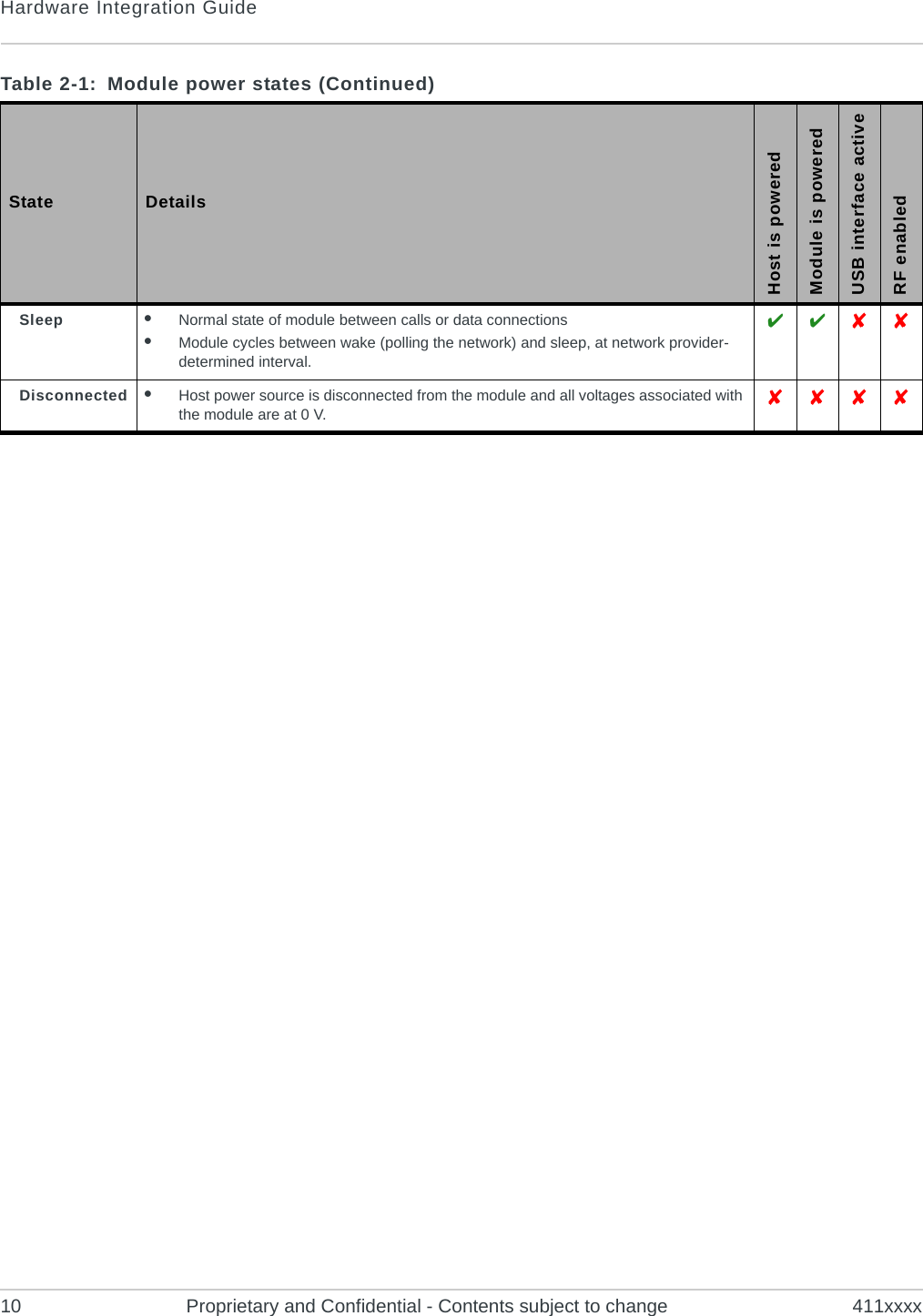
![Rev 1 Dec.12 Proprietary and Confidential - Contents subject to change 922: PowerPower supplyThe host provides power to the MC8805 through multiple power and ground pins.The host must provide safe and continuous power at all times; the module does not have an independent power supply, or protection circuits to guard against electrical issues.For detailed pinout and voltage / current requirements of this module, see the AirPrime MC8805 Product Technical Specification Document & Customer Design Guidelines.Module power statesThe module has four power states, as described in Ta b l e 2-1. Table 2-1: Module power states State DetailsHost is poweredModule is poweredUSB interface activeRF enabledNormal(Default state)•Module is active•Default state when VCC is first applied in the absence of W_DISABLE_N control•Module is capable of placing / receiving calls, or establishing data connections on the wireless network•Current consumption is affected by several factors, including:•Radio band being used•Transmit power•Receive gain settings•Data rate•Number of active Tx time slots Low power(‘Airplane mode’)•Module is active•Module enters this state:•Under host interface control:·Host issues AT+CFUN=0 ([1] AT Command Set for User Equipment (UE) (Release 6) (Doc# 3GPP TS 27.007))), or·Host asserts W_DISABLE_N, after AT!PCOFFEN=0 has been issued.•Automatically, when critical temperature or voltage trigger limits have been reached ](https://usermanual.wiki/Sierra-Wireless-ULC/MC8805/User-Guide-1878537-Page-9.png)
