Sierra Wireless ULC SL8084T Wireless Module User Manual Hardware Integration Guide for AirPrime SL8084T
Sierra Wireless Inc. Wireless Module Hardware Integration Guide for AirPrime SL8084T
TempConfidential_AirPrime - SL8084T - Hardware Integration Guide - Rev2.1
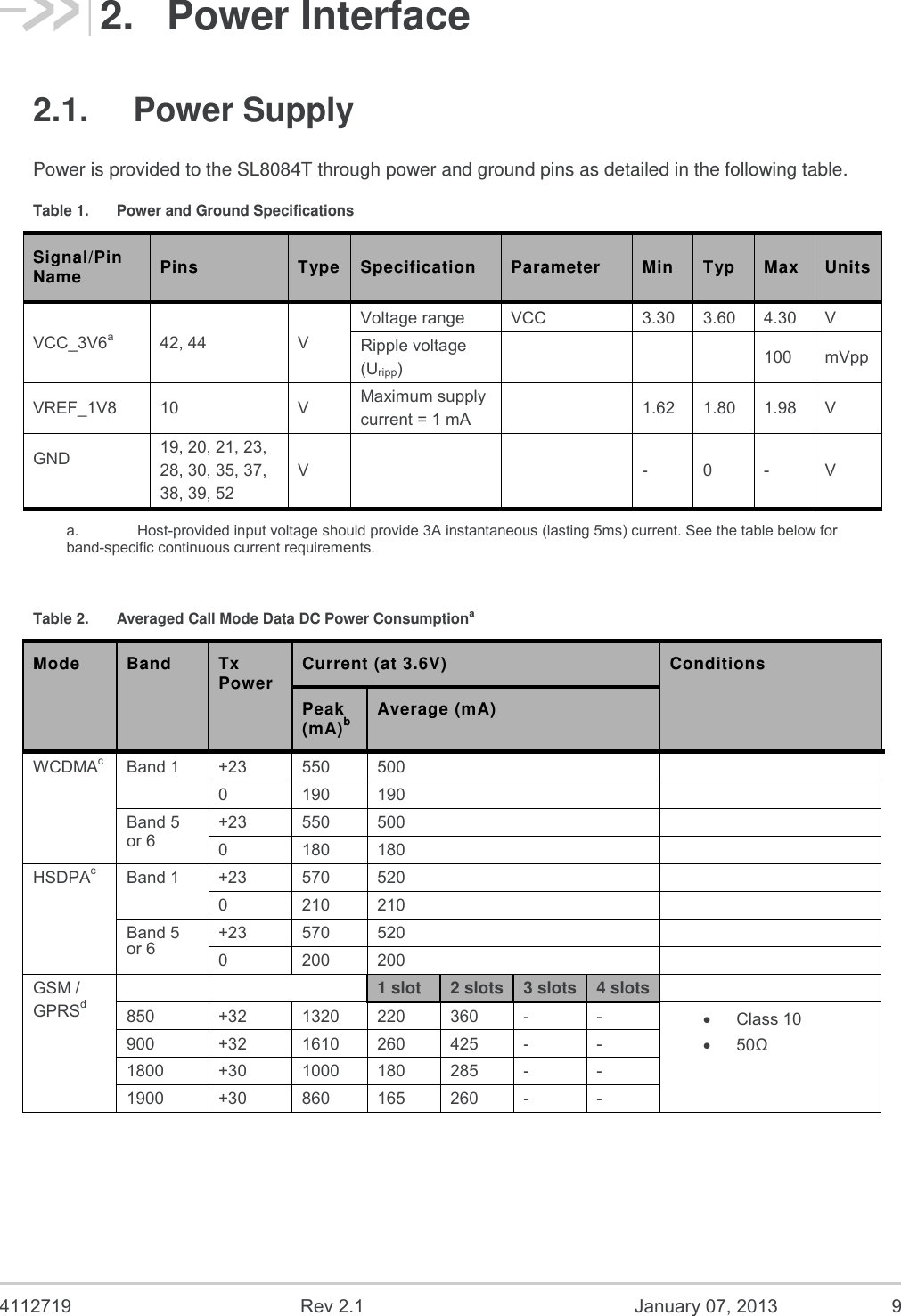
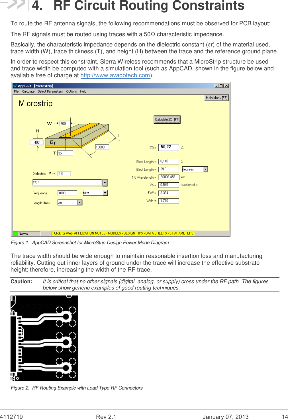
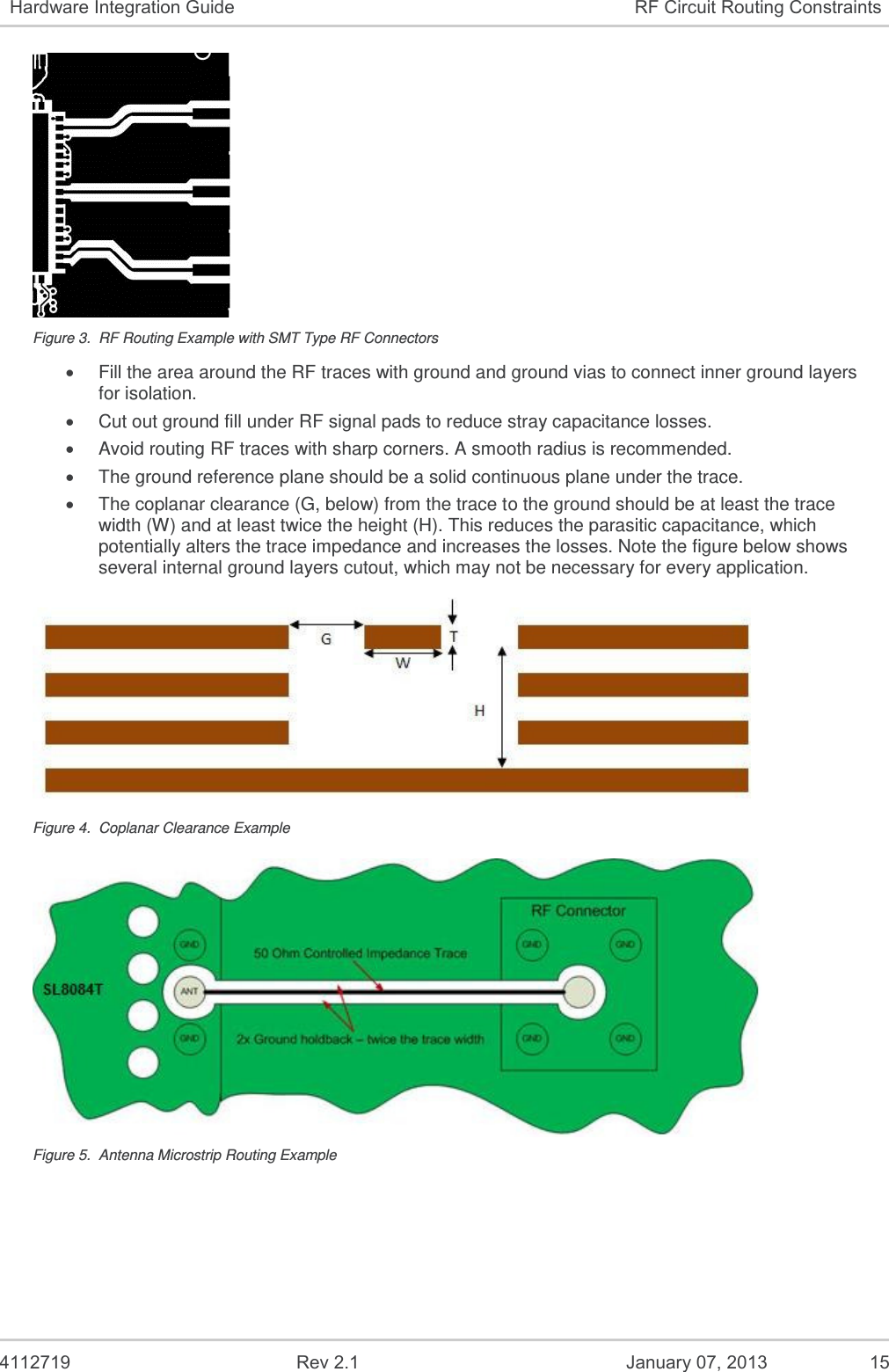
![4112719 Rev 2.1 January 07, 2013 8 1. Introduction The Sierra Wireless AirPrime SL8084T soldered-down module forms the radio component for the products in which it is embedded. Module-specific performance and physical characteristics are described in document [2] AirPrime SL808x Product Technical Specification and Customer Design Guidelines. Note: An understanding of network technology, and experience in integrating hardware components into electronic equipment is assumed. 1.1. Hardware Development Components Sierra Wireless manufactures two hardware development components to facilitate the hardware integration process: AirPrime SL Socket Board – Adapter board into which an SL module is embedded. This board may be used as a stand-alone platform for basic hardware development. AirPrime SL Development Kit – Hardware development platform that integrates with the socket-up board. The development kit provides access to all of the interfaces supported by the SL module. For instructions on using the SL Development Kit, see document [1] Universal AirPrime SL Series Development Kit User Guide.](https://usermanual.wiki/Sierra-Wireless-ULC/SL8084T/User-Guide-1878609-Page-8.png)
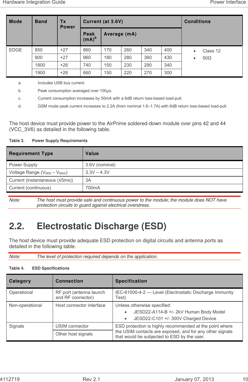
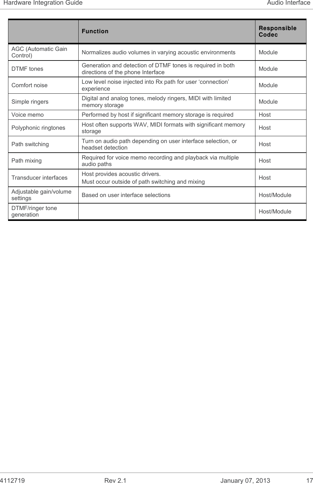
![4112719 Rev 2.1 January 07, 2013 16 5. Audio Interface The AirPrime SL8084T embedded module supports analog and PCM audio as summarized in the following tables. Refer to document [2] AirPrime SL808x Product Technical Specification and Customer Design Guidelines for detailed information about the audio interfaces. Table 7. Audio Interface Features Audio Type Feature Details Analog Implementation Supports analog audio processing Does not provide on-board filtering (except for blocking capacitors on microphone lines) Host must provide bias and signal filters Host should terminate unused audio lines with pull-down resistors Digital (PCM) Implementation Primary PCM supported to interface with external codec Power 1.8V (use VREG_MSME_1V8 as logic reference) Table 8. Audio Pin Description Audio Type Signal Name Pin # Description Notes Analog MIC_P 53 Microphone positive terminal In series with 0.1 μF DC blocking capacitor MIC_N 54 Microphone negative terminal In series with 0.1 μF DC blocking capacitor SPK_N 56 Speaker negative terminal SPK_P 57 Speaker positive terminal Digital PCM_SYNC 64 PCM synchronization bit 8 kHz PCM_DOUT 65 PCM output PCM_DIN 66 PCM input PCM_CLK 67 PCM clock 2 MHz for primary PCM mode 5.1. Audio Function Codec Responsibilities The responsibilities of the module codec and host codec for special functions are detailed in the following table. Table 9. Codec Responsible for Special Functions Function Responsible Codec FIR filtering Tx and Rx paths Module Noise suppression Required due to high sensitivity and gain in Tx path Module Echo cancellation Different for each audio path and environment (handset, headset, car kit, speakerphone) Module High pass filtering/slope filtering functions Required per phone acoustic requirements Module](https://usermanual.wiki/Sierra-Wireless-ULC/SL8084T/User-Guide-1878609-Page-16.png)
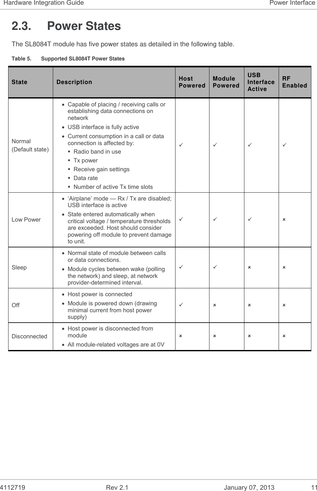
![4112719 Rev 2.1 January 07, 2013 20 7. References 7.1. Reference Documents [1] Universal AirPrime SL Series Development Kit User Guide Reference: WA_DEV_LG_UGD_003 [2] AirPrime SL808x Product Technical Specification and Customer Design Guidelines Reference: 4111992 7.2. Acronyms and Definitions Acronym or Term Definition AGC Automatic Gain Control BER Bit Error Rate - a measure of receive sensitivity BLER Block Error Rate Call Box Base Station Simulator - Agilent E8285A or 8960, Rohde & Schwarz CMU200 CDMA Code Division Multiple Access dB Decibel = 10 x log10 (P1/P2) P1 is calculated power; P2 is reference power Decibel = 20 x log10 (V1/V2) V1 is calculated voltage, V2 is reference voltage dBm Decibels, relative to 1 mW - Decibel(mW) = 10 x log10 (Pwr (mW)/1mW) DUT Device Under Test EDGE Enhanced Data rates for GSM Evolution EM Embedded Module ESD ElectroStatic Discharge FER Frame Error Rate - a measure of receive sensitivity GPRS General Packet Radio Services GPS Global Positioning System GSM Global System for Mobile communications Hz Hertz = 1 cycle/second inrush current Peak current drawn when a device is connected or powered on IS-2000 3G radio standards for voice and data (CDMA only) IS-95 2G radio standards targeted for voice (cdmaONE) LDO Low Drop Out - refers to linear regulator MHz MegaHertz = 10E6 Hertz (Hertz = 1 cycle/second) MIO Module Input/Output MPE Maximum Permissible Exposure—the level of radiation to which a person may be exposed without hazardous effect or adverse biological changes OTA Over-The-Air or Radiated through the antenna PCS Personal Communication System - PCS spans the 1.9 GHz radio spectrum](https://usermanual.wiki/Sierra-Wireless-ULC/SL8084T/User-Guide-1878609-Page-20.png)