Sierra Wireless 19251390X2 Alarm Communication Module User Manual NX594 GSM Manual
Numerex Corporation Alarm Communication Module NX594 GSM Manual
User Manual

NX-594 SMSXpress Module
Installation Manual
Copyright
Copyright © 2008 NUMEREX. All rights reserved.
No part of this publication may be reproduced or used in any form without
permission in writing from Numerex. This includes electronic or mechanical
means, such as photocopying, recording, or information storage and retrieval
systems. The material in this manual is subject to change without notice.
Warrantee The Company's Products Are Subject To The Following Limited Warranty:
The company's products are warranted against defects in materials and workmanship
for a period of one (1) year following the date of purchase, under normal use and
service.
The company's obligation under this limited warranty is limited to repairing or replacing
with reconditioned parts, at its option, any product proven to be defective in
materials or workmanship under normal use and service. The company shall have no
obligation if its products are altered or improperly repaired or serviced by any party
other than the company. Except as set forth herein, the company's products are
delivered
without warranty of any kind, whether express or implied, including any warranty
of merchantability and any warranty that the company's products are fit for any particular
purpose. In no event shall company be liable for actions of third parties which
may affect the performance of its products or other factors outside company's control
which may require installation of additional equipment or affect the performance of the
products.
THE EXTERNAL ANTENNAS USED FOR THIS MODULE MUST PROVIDE A SEPARATION
DISTANCE OF AT LEAST 20 CM FROM ALL PERSONS AND MUST NOT BE CO-LOCATED
OR OPERATING IN CONJUNCTION WITH ANY OTHER ANTENNA OR TRANSMITTER
.
Disclaimer
Numerex reserves the right to make changes to any software or product to
improve reliability, function or design.
NUMEREX (“NUMEREX”) assumes no
responsibility for inaccuracies or omissions and specifically disclaims any liabilities,
losses, or risks, personal or otherwise, incurred as a consequence, directly or indirectly,
of the use or application of any of the contents of this document.
This publication may contain examples of screen captures and reports used in daily
operations. Examples may include fictitious names of individuals and companies. Any
similarity to names and addresses of actual businesses or persons is entirely
coincidental.
Trademarks and
patents
NUMEREX and the NUMEREX monogram are registered trademarks of Numerex. Other
trade names used in this document may be trademarks or registered trademarks of the
manufacturers or vendors of the respective products.
FCC & I
NDUSTRY
C
ANADA
R
EGULATORY
C
OMPLIANCE
This device complies with Part 15 of the FCC Rules. Operation is subject to the following two conditions: (1) this
device may not cause harmful interference, and (2) this device must accept any interference received, including
interference that may cause undesired operation. This equipment has been tested and found to comply with the limits
for a Class B digital device, pursuant to Part 15 of the FCC Rules. These limits are designed to provide reasonable
protection against harmful interference in a residential installation. This equipment generates, uses and can radiate
radio frequency energy and, if not installed and used in accordance with the instructions, may cause harmful
interference to radio communications. However, there is no guarantee that interference will not occur in a particular
installation. If this equipment does cause harmful interference to radio or television reception, which can be
determined by turning the equipment off and on, the user is encouraged to try to correct the interference by one or
more of the following measures:
•
Reorient or relocate the receiving antenna.
•
Increase the separation between the equipment and receiver.
•
Connect the equipment into an outlet on a circuit different from that to which the receiver is connected.
•
Consult the dealer or an experienced technician for help.
FCC RF Exposure Information
In August 1996 the Federal Communications Commission (FCC) of the United States with its action in Report and
Order FCC 96-326 adopted an updated safety standard for human exposure to radio frequency electromagnetic
energy emitted by FCC regulated transmitters. Those guidelines are consistent with the safety standard previously
set by both U.S. and international standards bodies. The design of this module complies with the FCC guidelines and
these international standards. For more information about RF exposure, please visit the FCC website at www.fcc.gov.
THE TERM "IC:" BEFORETHE CERTIFICATION/REGISTRATION NUMBER ONLY SIGNIFIES THAT THE
INDUSTRY CANADA TECHNICAL SPECIFICATIONS WERE MET. THE EXTERNAL ANTENNAS USED FOR
THIS MODULE MUST PROVIDE A SEPARATION DISTANCE OF AT LEAST 20 CM FROM ALL PERSONS AND
MUST NOT BE CO-LOCATED OR OPERATING IN CONJUNCTION WITH ANY OTHER ANTENNA OR
TRANSMITTER
Contents
Preface . . . . . . . . . . . . . . . . . . . . . . . . . . . . . . . . . . . . . . . . . . . . . . .
.
. . . . . . . . . . . . . . . . . . . . .1
Conventions used in this document . . . . . . . . . . . . . . . . . . . . . . . . . . . . . . . . . . . . .
. . . . . . . . . . . . . . . . . . . . . . . . . .1
Safety terms and symbols. . . . . . . . . . . . . . . . . . . . . . . . . . . . . . . . . . . . . . . . . . . . . . . .. . .
. . . . . . . . . . . . . . . . . . . . . . . . .1
Product overview . . . . . . . . . . . . . . . . . . . . . . . . . . . . . . . . . . . . . . . . . . . . . . . . . . . . . . . . . . . .2
Website activation of new and replacement modules. . . . . . . .
. . . . . . . . . . . . . . . . . . . . . . . . . . . . . . . . . . . . . . . . . . . . . .2
Enrolling the module . . . . . . . . . . . . . . . . . . . . . . . . . . . . . . . . . . . . . . . . . . . . . . . . . . . . . . . . . . . . . . . . . . . . . .
. . . . . . . .3
Module address. . . . . . . . . . . . . . . . . . . . . . . . . . . . . . . . . . . . . . . . . . . . . . . . . . . . . . . . . . . . . . . . . . . . . . . . . . . . . . . . . . . .3
Installation. . . . . . . . . . . . . . . . . . . . . .
. . . . . . . . . . . . . . . . . . . . . . . . . . . . . . . . . . . . . . . . . . . .4
Mounting . . . . . . . . . . . . . . . . . . . . . . . . . . . . . . . . . . . . . . . . . . . . . . . . . . . . . . . . . . . . . . . . . . . . . . . . . . . . . .
. . . . . . . . . . .4
Wiring . . . . . . . . . . . . . . . . . . . . . . . . . . . . . . . . . . . . . . . . . . . . . . . . . . . . . . . . . . . . . . . . . . . . . . . . . . . . . . . . . . . . . . . . . .5
Module LEDs . . . . . . . . . . . . . . . .
. . . . . . . . . . . .. . . . . . . . . . . . . . . . . . . . . . . . . . . . . . . . . . . . . . . . . . . . . . . . . . . . . . . . . .6
Programming. . . . . . . . . . . . . . . . . . . . . . . . . . . . . . . . . . . . . . . . . . . . . . . . . . . .
. . . . . . . . . . . .8
Programming data. . . . . . . . . . . . . . . . . . . . . . . . . . . . . . . . . . . . . . . . . . . . . . . . . . . . . . . . . . . . . . . . . . . . . . . . . . . . . . . . .9
Location 0, programming the mode. . . . . . . . . .
. . . . . . . . . . . . . . . . . . . . . . . . . . . . . . . . . . . . . . . . . . . . . . . . . . . . . . . . .10
Location 1, feature selection. . . . . . . . . . . . . . . . . . . . . . . . . . . . . . . . . . . . . . . . . . . . . . . . . . . . . . .
. . . . . . . . . . . . . . . . . .10
Location 2, events to report to central station. . . . . . . . . . . . . . . . . . . . . . . . . . . . . . . . . . . . . . . . . . . . . . . . . . . . . . . . . . . .11
Location 3, special events to report to central
station . . . . . . . . . . . . . . . . . . . . . . . . . . . . . . . . . . . .. . . . . . . . . . . . . . . . .11
Location 4, events to report to e-mail . . . . . . . . . . . . . . . . . . . . . . . . . . . . . . . . . . . . . . . . . . . . . . . . . . .
. . . . . . . . . . . . . . .12
Location 5, special events to report to e-
mail . . . . . . . . . . . . . . . . . . . . . . . . . . . . . . . . . . . . . . . . . . . . . . . . . . . . . . . . . . . .12
Location 6, events to report to pager. . . . . . . . .
. . . . . . . . . . . . . . . . . . . . . . . . . . . . . . . . . . . . . . . . . . . . . . . . . . . . . . . . . .13
Location 7, special events to report to pager. . . . . . . . . . . . . . . . . . . . . . . . . . . . . . . . . . . . . . . . . . . . . . .
. . . . . . . . . . . . . .13
Location 8, events to report to central station. . . . . . . . . . . . . . .. . . . . . . . . . . . . . . . . . . . . . . . . . . . . . . . . . . . . . . . . . . . . .14
Location 9, special events to report to central station
. . . . . . . . . . . . . . . . . . . . . . . . . . . . . . . . . . . .. . . . . . . . . . . . . . . . .14
Location 10, events to report to e-mail . . . . . . . . . . . . . . . . . . . . . . . . . . . . . . . . . . . . . . . . . . . . . . . . . . . . . .
. . . . . . . . . . .15
Location 11, special events to report to e-
mail. . . . . . . . . . . . . . . . . . . . . . . . . . . . . . . . . . . . . . . .. . . . . . . . . . . . . . . . . . . .15
Location 12, events to report to pager. . . . . . . . . . . . .
. . . . . . . . . . . . . . . . . . . . . . . . . . . . . . . . . . . . . . . . . . . . . . . . . . . . .16
Location 13, special events to report to pager . . . . . . . . . . . . . . . . . . . . . . . . . . . . . . . . . . . . . . . .. . . . . . . . . . .
. . . . . . . . .16
Programming worksheets . . . . . . . . . . . . . . . . . . . . . . . . . . . . . . . . . . . . . . . . . . . . . . . . . . . . . . . . . . . . . . . . . . . . . . . . . . .17
Specifications. . . . . . . . . . . . . . . . . .. . . . . .
. . . . . . . . . . . . . . . . . . . . . . . . . . . . . . . . . . . . . . .24
Support . . . . . . . . . . . . . . . . . . . . . . . . . . . . . . . . . . . . . . . . . . . . . . . . . . . . . . . . . . . . . . . . . . .25
Contacting technical support . . . . . . . . . . . . . . . . . . . . . . . . . . . . . . . . . . . . . . . . . . . . . . . . . . . . . . . . . . . . . . . . . . . . . . . .25
Index . . . . . . . . . . . . . . . . . . . . . . . . . . . . .. . . . . . . . . . . . . . . . . . . . . . . .
. . . . . . . . . . . . . . . . .27
Preface
This is the NUMEREX NX-594 SMSXpress Module Installation Manual for model NX-594. This
document includes an overview of the product and detailed instructions explaining:
• how to install; and
• how to program the module.
There is also information describing how to contact technical support if you have questions or concerns.
To use this document effectively, you should have a basic knowledge of electrical wiring and low-voltage
electrical connections.
Read these instructions and all ancillary documentation entirely before installing or operating this product.
The most current versions of this and related documentation may be found on our website. Refer to
Contacting technical support on page 25 for instructions on accessing our online publication library.
Note:
A qualified service person, complying with all applicable codes, should perform all required hardware installation.
Conventions used in this document
The following conventions are used in this document:
Safety terms and symbols
These terms may appear in this manual:
CAUTION:
Cautions identify conditions or practices that may result in damage to the equipment or other property.
WARNING:
Warnings identify conditions or practices that could result in equipment damage or serious personal injury.
Bold Menu items and buttons.
Italic Emphasis of an instruction or point; special terms.
File names, path names, windows, panes, tabs, fields, variables, and other GUI elements.
Titles of books and various documents.
Blue italic (Electronic version.) Hyperlinks to cross-references, related topics, and URL addresses.
Text that displays on the computer screen.
Monospace
Programming or coding sequences.
Product overview
The NX-594 is a microprocessor-controlled GSM interface module used to connect the NetworX series of
control panels to GSM cellular networks for event reporting. The module can be used for primary, backup, or
additional reporting when used in conjunction with the panel communicator or other optional reporting
modules. Flexible event selection allows only specific messages to be reported, keeping airtime to a
minimum. The module has 9 LEDs to provide extensive diagnostic and setup information.
Website activation of new and replacement modules
You can activate and manage the module via our website address: www.numerexsolutions.com
You must have a dealer account set up before you can proceed. If your company already has an account set
up, do the following:
1 At the bottom of the web page, click the activation link. The member Login screen appears.
2 At the Login screen, type your login name and password, then click Login.
3 The following options are available on the site map. If not displayed, select Site map under the
main menu.
Activate digital unit (new). This will activate the GSM module (NX-594). Enter the serial number of
the module (located on the front of the unit). The serial number must contain 10 digits. Multiple modules
can be added from this screen.
Edit unit settings.
Complete the following information based on the way you want to configure the
reporting for the module:
• Select the unit you have just activated.
• Add the account name to the Unit name field.
• Select your Notification Method 1.
• Change TX Retries to 8 (maximum allowed).
•
• Go to the appropriate field for the Method 1 that was chosen (Alpha, E-mail, or Central
Station).
• If Alpha pager, the PIN is required.
• If Central Station, enter the receiver phone number and central station A/C number.
• Select a second Notification Type, if needed.
• Notification Enabled should read “Yes”.
4. Click Update.
Enrolling the module
The NetworX control panels have the ability to automatically find and store in memory the presence of all
keypads, zone expanders, wireless receivers, and any other device on the keypad buss. This allows these
devices to be supervised by the control panel. To enroll the devices, enter program mode of the NX control
panel using the procedure described in the control panel documentation. When you exit program mode, the
control panel will automatically enroll all the devices. The enrolling process takes about 12 seconds, during
which time the service LED will illuminate. When using the LCD keypad, the “Service Required” message
will be displayed. User codes will not be accepted during the enrolling process. Once a module is enrolled, if
the control panel does not detect it, the service LED will illuminate.
Module address
The GSM module has a fixed address of 76. When programming the module, enter program mode and select
the device address as 76 (see Programming on page 8).
Installation
To install the module you will need to mount and wire the board.
Mounting
Inside the can, several two-holed insertion points have been constructed. This allows for either vertical or
horizontal placement of the modules. The insertion points have two sizes of holes, a larger hole and a smaller
hole. The black plastic PCB guides are grooved on one edge
where the PC board will be seated. The end with
the half-moon protrusion fits into the larger hole. The smaller hole is for the screw.
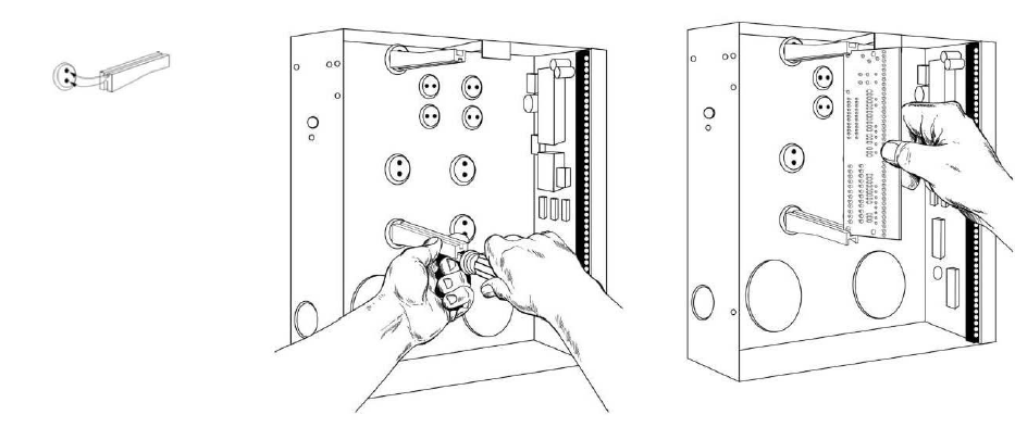
To mount the board, see Figure 2 and do the following:
1 Place the first black plastic PCB guide in the top insertion point, grooved edge downward. The
half-moon protrusion will be in the large hole. It does not require force.
2 Insert one of the provided screws into the smaller hole (from the inside of the can) to secure it in
place. A screwdriver should reach through the notch that runs the length of the guide to tighten the screw.
3 Position the second PCB guide opposite of the first (grooved edge up) and placed in the lower
insertion point, using the same procedure.
4 Once mounted, screw it in securely.
5 Slide the board in the grooves of both guides.
Note: Older style enclosures did not provide an exit hole for the antenna included with the GSM module. In such
cases, you must either drill a new hole (5/8 in.) on top of the can or use an optional external antenna (NX-501E-GSM).
Figure 2. Mounting the board
Wiring
Table 1 shows the maximum wire run for different wire gauges.
Table 1. Maximum wire run
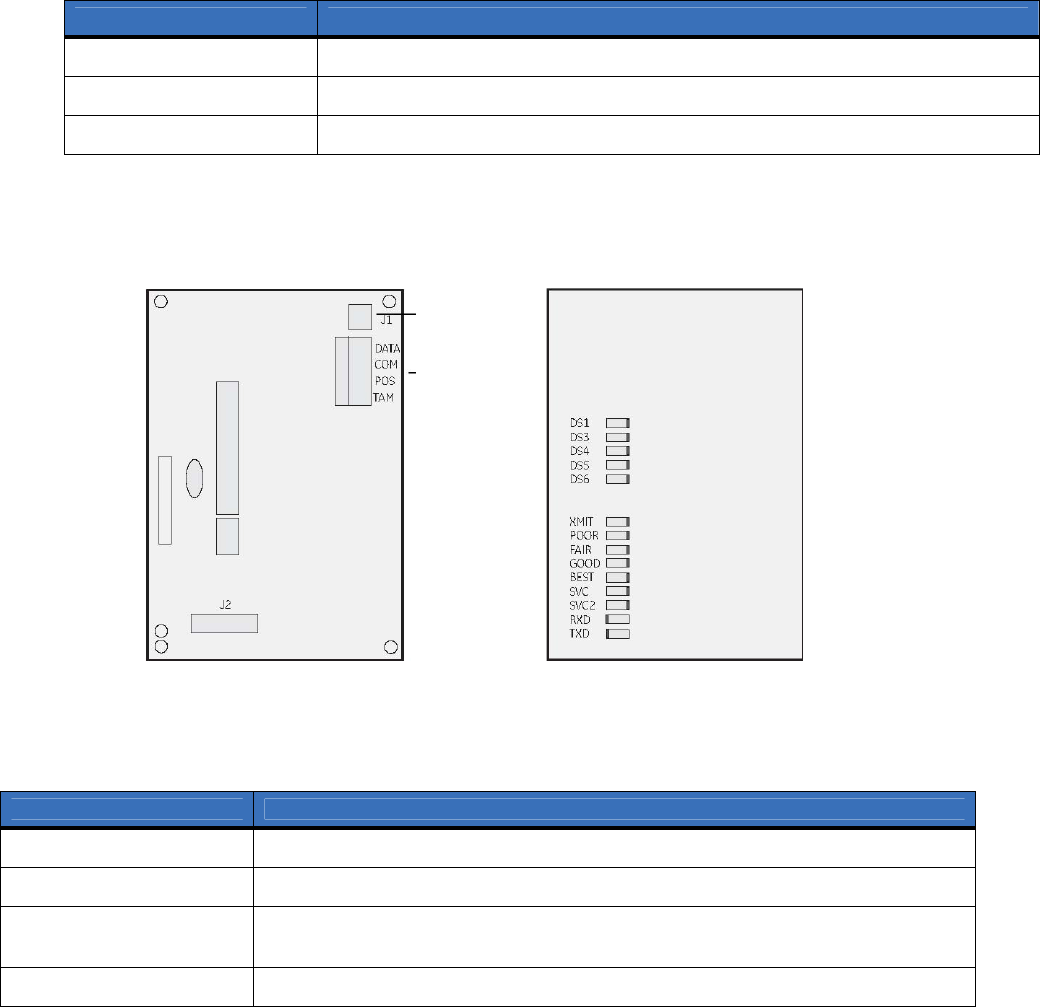
Figure 3 shows the module wiring terminals and LEDs on the board
Figure 3. Wiring terminals
Board front Board back
Tampe
r
switch
Wiring
terminals
LEDs
Table 2 describes the wiring terminals.
Table 2. Wiring terminals
Length in feet Wire gauge (connected to NX control panel or NX320E power supply)
10 20
50 18
100 16
Terminal Description
DATA Connect to the KP DATA terminal of the panel.
COM Connect to the KP COM terminal of the panel.
POS Connect to the KP POS terminal of the panel. Refer to Specifications on page 24 for
power consumption.
TAMPER Normally closed.

Module LEDs
The module has 9 green LEDs along the back of the board. These LEDs provide valuable inform
ation about
the status of the module as described in Table 3.
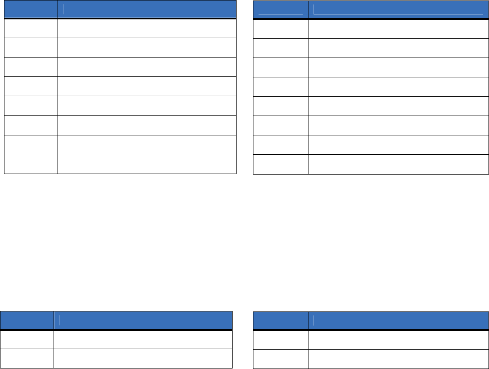
Table 3. Module LEDs
LED Description
DS1 - Buss Proper circuitry operation.
DS2 - XMIT Transmitting message packet to the tower
DS3 - SVC Cellular service available
DS4 - BEST
DS5 - GOOD
DS6 - FAIR
DS7 - POOR
The LEDs will either be off, on, flashing slow, or flashing fast depending on the dB of
the signal. Refer to Table 4 on page 7 for details.
DS9 - RXD Receiving data from GSM radio.
DS8 - TXD Sending data to GSM radio.

Table 4 describes the dB signals for the LEDs.
Table 4. LEDs and dB signals
dB
Poor Fair Good Best
-114
-107 Off Off Off Off
-106
-104 Slow Off Off Off
-103
-101 Fast Off Off Off
-100
-98 On Off Off Off
-97
-95 On Slow Off Off
-94
-92 On Fast Off Off
-91
-89 On On Off Off
-88
-86 On On Slow Off
-85
-83 On On Fast Off
-82
-80 On On On Off
-79
-77 On On On Slow
-76
-74 On On On Fast
-73
Higher On On On On
Programming
You can program the module using the LED keypad or the LCD keypad. To progra
m the module using the
LED keypad, do the following:
Enter program mode
To enter program mode, press * 8
. The Stay, Chime, Exit, Bypass, and Cancel LEDs on the keypad will flash.
Enter the “go to program code”. The factory default is 9 7 1 3. If the code is valid, the Service LED on the
keypad will flash and the five function LEDs will illuminate steady. You are now in program mode and can
select the module to program.
Select the module to program
To select the module to program, press 7 6 # (the address of this GSM module). The Armed LED on the
keypad will illuminate while it is waiting for a programming location to be entered.
Factory default the module
To return the module to factory defaults, press 9 1 0 #. The keypad will beep three times indicating that
loading is in progress. Remember you will erase any values you may have entered previously.
Programming a location
Once the number of the module to be programmed has been entered, the Armed LED on the keypad will
illuminate while it is waiting for a programming location to be entered.
Note: If an attempt is made to program an invalid entry for a particular segment, the keypad sounder will emit a triple
error beep, and remain in that segment waiting for a valid entry.
To enter a location, enter the location number (1 to 13) and press #
. The Armed LED will flash. If the location
is valid, the Armed LED will extinguish, the Ready LED will illuminate, and the zone LEDs will show the
data for the first segment of this location.
To change location data, enter the changed data. The Ready LED will flash to indicate a data change in
progress and will continue until the data is saved. Press * to save the new data. The keypad will advance to
the next segment and display its data. These steps are repeated until the last segment is reached.
To exit a location, press #. The Ready LED will extinguish. The Armed LED will illuminate waiting for a
new programming location to be entered.
To review the data, enter the location number and press #. The Armed LED will flash. If the location number
is valid, the Armed LED will extinguish, the Ready LED will illuminate, and the zone LEDs will show the
binary data for the first segment of this location. Press * to display the next segment data. Each time you press
*, the data of the next segment will be displayed for review.
Exit program mode
Press Exit to exit this programming level. Press Exit a second time to completely exit programming.
LCD keypad programming
All steps required for programming are the same as those described for the LED keypad. The LCD keypad
display will prompt you for the data required. While in programming mode, and not in a location, the number
in parenthesis is the location you were previously changing. For example, if the display reads, “Ent
er location,
then # (5)”, it is reminding you that location 5 was the last location you programmed.
Programming data
Programming data is either numerical data, or feature selection data.
Numerical data
To program numerical data, enter a number from 0 to 255 on the numeric keys of the keypad. To view the
data in a location, a binary process is used. With this process, the LEDs for zones 1 through 8 are used, and
the numeric equivalents of their illuminated LEDs are added together to determine the data in a programming
location. The numeric equivalents of these LEDs are as follows:
Zone 1 LED = 1 Zone 3 LED = 4 Zone 5 LED = 16 Zone7 LED = 64
Zone 2 LED = 2 Zone 4 LED = 8 Zone 6 LED = 32 Zone8 LED = 128
For example, if the numerical data to be programmed in a location is “66”, press 6 6
on the keypad. The LEDs
for Zone 2 and Zone 7 will illuminate indicating 66 is in that location (2 + 64 = 66). Once the data is
programmed, press * to enter the data and advance to the next segment of that location.
After the last segment of a location is programmed, press *
to exit that location, turn the Ready LED off, and
the Armed LED on. You are now ready to enter another programming location.
If an attempt is made to program a number too large for a particular segme
nt, the keypad sounder will emit a
triple beep, indicating an error, and remain in that segment waiting for a valid entry.
Feature selection data
Feature selection data will display the current condition (on or off) of eight features associated with the
programming location and segment selected. Pressing a button on the touchpad (1 through 8) that corresponds
to the feature number within a segment will toggle (on/off) that feature. Pressing any numeric key between 1
and 8 for selection of a feature will make the corresponding LED illuminate (feature on). Press the number
again, and the LED will extinguish (feature off).
You will see that numerous features can be selected from within one segment. For instance, if all eight
features of a segment are desired, pressing 1 2 3 4 5 6 7 8 will turn on LEDs 1 through 8 as you press the
keys, indicating that those features are enabled.
Note: On LCD keypads, the numbers of the enabled features will be displayed. However, the features not enabled will
display a hyphen (-).
After you select the desired setting for this segment, press *
to enter the data and automatically advance to the
next segment of the location. When you are in the last segment of a location and press * to enter the data, you
will exit that location. The Ready LED will turn off and the Armed LED will turn on. You are now ready to
enter another programming location.

Location 0, programming the mode
This location has five numeric data segments. This location contains the system identification numb
er (SID).
Factory default is 0-0-0-0-0 for AutoSID.
Note:
If manually entering an SID, use leading zeroes.
Location 1, feature selection
This location has four segments. Segment 1 contains the options to be programmed for the functioning of this
module. Factory default for all Segment 1 options is off. Table 5 describes the options
Table 5. Segment 1 options
Segment 2 programs host acknowledge
ment requirements. Factory default for all Segment 2 options is off.
Table 6 describes the options.
Table 6. Segment 2 options
1 Daily test will be performed 24 hours (± 10 minutes) from time this option is programmed.
2 Weekly test will be performed 168 hours (± 10 minutes) from time this option is programmed.
3 Some older SIA DCS compatible receivers may not support the use of area (partition) modifiers. In such cases, the area
modifier must be disabled (Option 8 on).
Segments 3 and 4 are reserved for future use.
Option Description On Off
1 Format SIA Contact ID
2 Test signal Daily
1
Weekly
2
3 System preference Use A or B side only No preference
4 B side preference B side (if option 3 is on) A side
5 Alternate MIN Disabled Enabled
6 Disable cellular service LEDs Disabled Enabled
7 Enable tamper switch Enabled Disabled
8 Disable SIA DCS area modifier
3
Disabled Enabled
Options Description On Off
1 Central station messages Enabled Disabled
2 E-mail messages Enabled Disabled
3 Pager messages Enabled Disabled
4 Periodic test signals Enabled Disabled
5 to 8 Reserved for future use.

Location 2, events to report to central station
Phone fault detected. This location has 16 segments.
Note:
Reporting must be enabled in the control panel for this location to function.
This location selects the partitions to include when reporting to the central station. To exclude any partition
from reporting, turn off the LED corresponding to that particular partition number. Enter the numbers of the
partitions to include for each type of report found in segments 1 through 16. Factory default is all partitions on
for segment 1; all partitions off for segments 2 to 16.
Table 7 describes the segment options.
Table 7. Location 2 options
Location 3, special events to report to central station
Phone fault detected. This location has 8 segments.
This location selects the partitions to include when reporting special events to the central station. To exclude
any partition from reporting, simply turn off the LED corresponding to that particular partition number. Enter
the numbers of the partitions to include for each type of report found in segments 1 through 4. Factory default
is all partitions off for segment 1 and 3; all partitions on for segments 2 and 4. Segments 5 to 8 are reserved
for future use.
Table 8 describes the segment options.
Table 8. Location 3 options
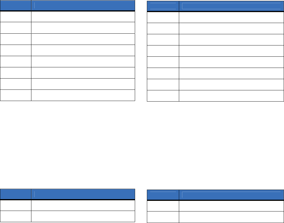
Segment Description
1 Alarms
2 Open/close
3 Bypass
4 Zone trouble
5 Power trouble (AC failure or low battery)
6 Siren and telephone fault
7 Test reports
8 Program, download, and log full
Segment Description
9 Tampers
10 Short circuit and ground fault
11 Sensor lost
12 Sensor low battery
13 Expander trouble
14 Failure to communicate
15 Zone activity monitor
16 Reserved for future use.
Segment Description
1 Alarm restores
2 Telephone fault
Segment Description
3 Start download
4 Fail to communicate, data lost
Location 4, events to report to e-mail
Phone fault detected. This location has 16 segments.
Note:
Reporting must be enabled in the control panel for this location to function.
This location selects the partitions to include when reporting to e-mail. To exclude any partition from
reporting, turn off the LED corresponding to that particular partition number. Enter the numbers of the
partitions to include for each type of report found in segments 1 through 16. Factory default is all partitions
off. for all segments.
Table 9 describes the segment options.
Table 9. Location 4 options
Location 5, special events to report to e-mail
Phone fault detected. This location has 8 segments.
This location selects the partitions to include when reporting special events to e-
mail. To exclude any partition
from reporting, turn off the LED corresponding to that particular partition number. Enter the numbers of the
partitions to include for each type of report found in segments 1 through 4. Factory default is all partitions off
for all segments. Segments 5 to 8 are reserved for future use.
Table 10 describes the segment options.
Segment Description
1 Alarms
2 Open/close
3 Bypass
4 Zone trouble
5 Power trouble (AC failure or low battery)
6 Siren and telephone fault
7 Test reports
8 Program, download, and log full
Segment Description
9 Tampers
10 Short circuit and ground fault
11 Sensor lost
12 Sensor low battery
13 Expander trouble
14 Failure to communicate
15 Zone activity monitor
16 Reserved for future use.
Table 10. Location 5 options
Segment Description
1 Alarm restores
2 Telephone fault
Segment Description
3 Start download
4 Fail to communicate, data lost

Location 6, events to report to pager
Phone fault detected. This location has 16 segments.
Note:
Reporting must be enabled in the control panel for this location to function.
This location selects the partitions to include when reporting to a pager. To exclude any partition from
reporting, turn off the LED corresponding to that particular partition number. Enter the numbers of the
partitions to include for each type of report found in segments 1 through 16. Factory default is all partitions
off. for all segments.
Table 11 describes the segment options.
Location 7, special events to report to pager
Phone fault detected. This location has 8 segments.
This location selects the partitions to include when reporting special events to a pager. To exclude any
partition from reporting, turn off the LED corresponding to that particular partition number. Enter the
numbers of the partitions to include for each type of report found in segments 1 through 4. Factory default is
all partitions off for all segments. Segments 5 to 8 are reserved for future use.
Table 12 describes the segment options.
Table 11. Location 6 options
Segment Description
1 Alarms
2 Open/close
3 Bypass
4 Zone trouble
5 Power trouble (AC failure or low battery)
6 Siren and telephone fault
7 Test reports
8 Program, download, and log full
Segment Description
9 Tampers
10 Short circuit and ground fault
11 Sensor lost
12 Sensor low battery
13 Expander trouble
14 Failure to communicate
15 Zone activity monitor
16 Reserved for future use.
Table 12. Location 7 options
Segment Description
1 Alarm restores
2 Telephone fault
Segment Description
3 Start download
4 Fail to communicate, data lost

Location 8, events to report to central station
Phone line is good. This location has 16 segments.
Note:
Reporting must be enabled in the control panel for this location to function.
This location selects the partitions to include when reporting to the central station. To exclude any partition
from reporting, turn off the LED corresponding to that particular partition number. Enter the numbers of the
partitions to include for each type of report found in segments 1 through 16. Factory default is all partitions
off for all segments.
Table 13 describes the segment options.
Location 9, special events to report to central station
Phone line is good. This location has 8 segments.
This location selects the partitions to include when reporting special events to the central station. To exclude
any partition from reporting, turn off the LED corresponding to that particular partition number. Enter the
numbers of the partitions to include for each type of report found in segments 1 through 4. Factory default is
all partitions off for all segments. Segments 5 to 8 are reserved for future use.
Table 14 describes the segment options.
Table 13. Location 8 options
Segment Description
1 Alarms
2 Open/close
3 Bypass
4 Zone trouble
5 Power trouble (AC failure or low battery)
6 Siren and telephone fault
7 Test reports
8 Program, download, and log full
Segment Description
9 Tampers
10 Short circuit and ground fault
11 Sensor lost
12 Sensor low battery
13 Expander trouble
14 Failure to communicate
15 Zone activity monitor
16 Reserved for future use.
Table 14. Location 9 options
Segment Description
1 Alarm restores
2 Telephone fault
Segment Description
3 Start download
4 Fail to communicate, data lost

Location 10, events to report to e-mail
Phone line is good. This location has 16 segments.
Note:
Reporting must be enabled in the control panel for this location to function.
This location selects the partitions to include when reporting to e-mail. To exclude any partition from
reporting, turn off the LED corresponding to that particular partition number. Enter the numbers of the
partitions to include for each type of report found in segments 1 through 16. Factory default is all partitions
off. for all segments.
Table 15 describes the segment options.
Location 11, special events to report to e-mail
Phone line is good. This location has 8 segments.
This location selects the partitions to include when reporting special events to e-m
ail. To exclude any partition
from reporting, turn off the LED corresponding to that particular partition number. Enter the numbers of the
partitions to include for each type of report found in segments 1 through 4. Factory default is all partitions off
for all segments. Segments 5 to 8 are reserved for future use.
Table 16 describes the segment options.
Table 15. Location 10 options
Segment Description
1 Alarms
2 Open/close
3 Bypass
4 Zone trouble
5 Power trouble (AC failure or low battery)
6 Siren and telephone fault
7 Test reports
8 Program, download, and log full
Segment Description
9 Tampers
10 Short circuit and ground fault
11 Sensor lost
12 Sensor low battery
13 Expander trouble
14 Failure to communicate
15 Zone activity monitor
16 Reserved for future use.
Table 16. Location 11 options
Segment Description
1 Alarm restores
2 Telephone fault
Segment Description
3 Start download
4 Fail to communicate, data lost
Location 12, events to report to pager
Phone line is good. This location has 16 segments.
Note:
Reporting must be enabled in the control panel for this location to function.
This location selects the partitions to include when reporting to a pager. To exclude any partition from
reporting, turn off the LED corresponding to that particular partition number. Enter the numbers of the
partitions to include for each type of report found in segments 1 through 16. Factory default is all partitions
off. for all segments.
Table 17 describes the segment options.
Location 13, special events to report to pager
Phone line is good. This location has 8 segments.
This location selects the partitions to include when reporting special events to a pager. To exclude any
partition from reporting, turn off the LED corresponding to that particular partition number. Enter the
numbers of the partitions to include for each type of report found in segments 1 through 4. Factory default is
all partitions off for all segments. Segments 5 to 8 are reserved for future use.
Table 18 describes the segment options.
Table
17. Location 12 options
Segment Description
1 Alarms
2 Open/close
3 Bypass
4 Zone trouble
5 Power trouble (AC failure or low battery)
6 Siren and telephone fault
7 Test reports
8 Program, download, and log full
Segment Description
9 Tampers
10 Short circuit and ground fault
11 Sensor lost
12 Sensor low battery
13 Expander trouble
14 Failure to communicate
15 Zone activity monitor
16 Reserved for future use.
Table 18. Location 13 options
Segment Description
1 Alarm restores
2 Telephone fault
Segment Description
3 Start download
4 Fail to communicate, data lost

Programming worksheets
Location 0, System ID
Default of
0 0 0 0 0
(AutoSID). New data is ____________.
Location 1, Feature selection
Table 19. Location 1 worksheet
Segment Description Default Data
1 = SIA format (off = Contact ID) Off
1, Feature
selection
2 = Daily test signal (off = weekly) Off
3 = System preference (off = no preference) Off
4 = B side preference (off = A side) Off
5 = Disable alternate MIN Off
6 = Disable cellular service LEDs Off
7 = Enable tamper switch Off
8 = Disable SIA DCS area modifier Off
1 = Host acknowledgement for central station
messages Off
2 = Host acknowledgement for e-mail messages Off
3 = Host acknowledgement for pager messages Off
4 = Host acknowledgement for periodic test signals Off
2, Host
acknowledgement
required
5 to 8 = Reserved for future use

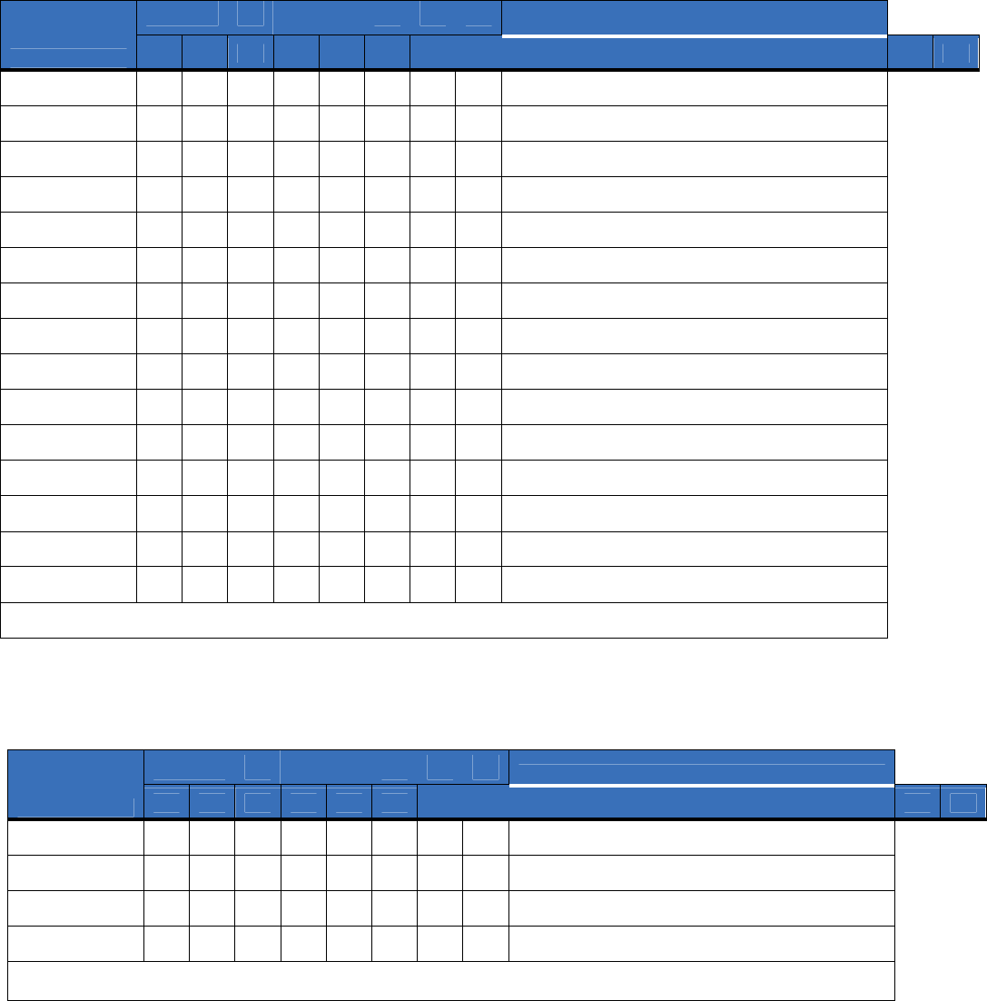
Location 2, Reporting events to central station
(Phone line fault detected)
Location 3, Reporting special events to central station
(Phone line fault detected)
Table 21. Location 3 worksheet
Table 20. Location 2 worksheet
Partition
Description
Segment 1 2 3 4 5 6 7 8
1
Alarms
2
Open/close
3
Bypass
4
Zone trouble
5
Power trouble (AC fail or low battery)
6
Siren and telephone fault
7
Test reports
8
Program, download, and log full
9
Tampers
10
Short circuit and ground fault
11
Sensor lost
12
Sensor low battery
13
Expander trouble
14
Fail to communicate
15
Zone activity monitor
16 Reserved for future use.
Partition
Description
Segment 1 2 3 4 5 6 7 8
1
Alarm restores
2
Telephone fault
3
Start download
4
Fail to communicate, data lost
5 to 8 Reserved for future
use.
Location 4, Reporting events to e
-
mail
(Phone line fault detected)
Location 5, Reporting special events to e
-
mail
(Phone line fault detected)
Table 23. Location 5 worksheet
Table 22. Location 4 worksheet
Partition
Description
Segment 1 2 3 4 5 6 7 8
1
Alarms
2
Open/close
3
Bypass
4
Zone trouble
5
Power trouble (AC fail or low battery)
6
Siren and telephone fault
7
Test reports
8
Program, download, and log full
9
Tampers
10
Short circuit and ground fault
11
Sensor lost
12
Sensor low battery
13
Expander trouble
14
Fail to communicate
15
Zone activity monitor
16 Reserved for future use.
Partition
Description
Segment 1 2 3 4 5 6 7 8
1
Alarm restores
2
Telephone fault
3
Start download
4
Fail to communicate, data lost
5 to 8 Reserved for future
use.
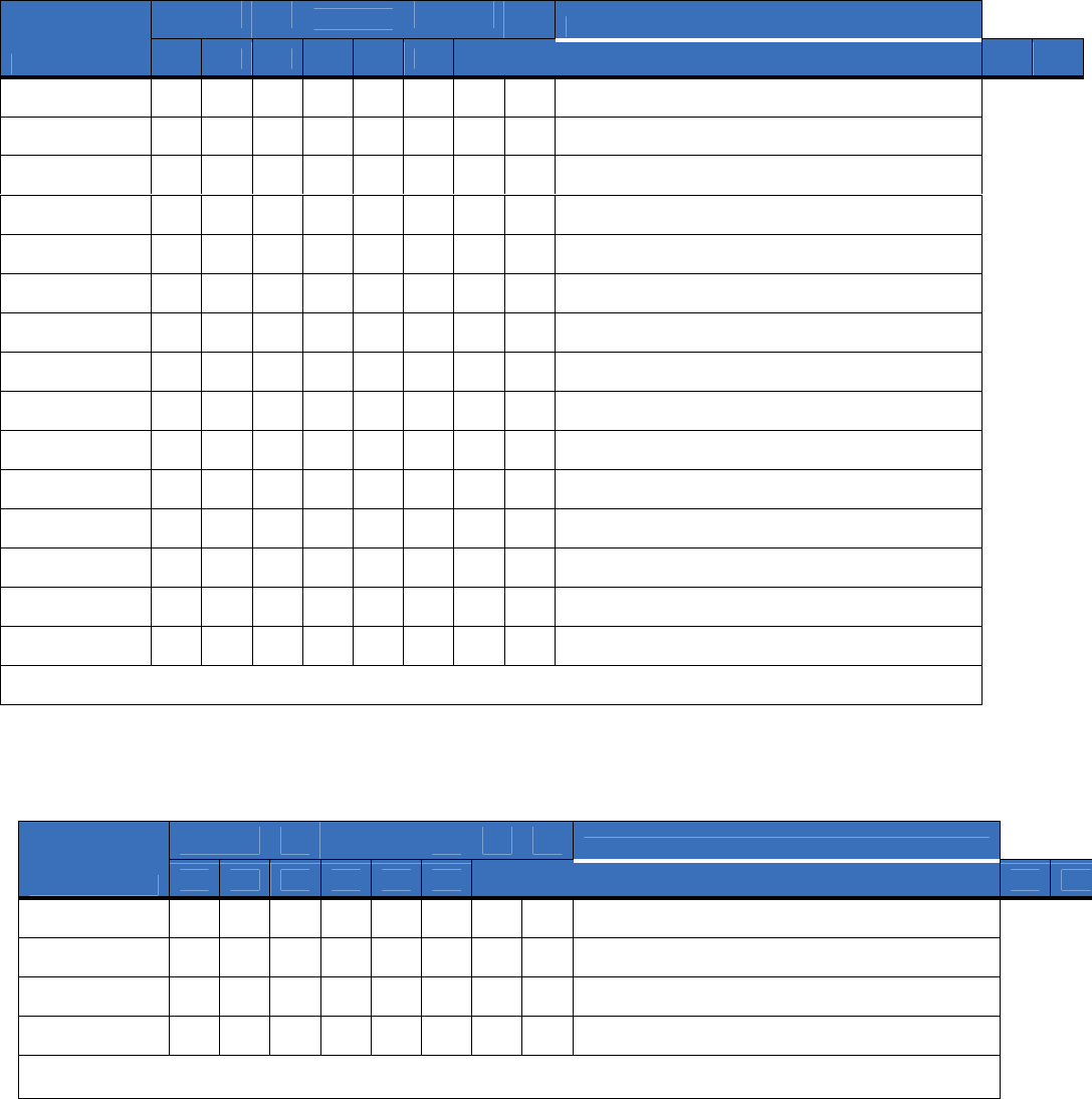
Location 6, Reporting events to pa
ge
r
(Phone line fault detected)
Location 7, Reporting special events to pa
ge
r
(Phone line fault detected)
Table 25. Location 7 worksheet
Table 24. Location 6 worksheet
Partition
Description
Segment 1 2 3 4 5 6 7 8
1
Alarms
2
Open/close
3
Bypass
4
Zone trouble
5
Power trouble (AC fail or low battery)
6
Siren and telephone fault
7
Test reports
8
Program, download, and log full
9
Tampers
10
Short circuit and ground fault
11
Sensor lost
12
Sensor low battery
13
Expander trouble
14
Fail to communicate
15
Zone activity monitor
16 Reserved for future use.
Partition
Description
Segment 1 2 3 4 5 6 7 8
1
Alarm restores
2
Telephone fault
3
Start download
4
Fail to communicate, data lost
5 to 8 Reserved for future
use.

Location 8, Reporting events to central station
(Phone line is good)
Location 9, Reporting special events to central station
(Phone line is good)
Table 27. Location 9 worksheet
Table 26. Location 8 worksheet
Partition
Description
Segment 1 2 3 4 5 6 7 8
1
Alarms
2
Open/close
3
Bypass
4
Zone trouble
5
Power trouble (AC fail or low battery)
6
Siren and telephone fault
7
Test reports
8
Program, download, and log full
9
Tampers
10
Short circuit and ground fault
11
Sensor lost
12
Sensor low battery
13
Expander trouble
14
Fail to communicate
15
Zone activity monitor
16 Reserved for future use.
Partition
Description
Segment 1 2 3 4 5 6 7 8
1
Alarm restores
2
Telephone fault
3
Start download
4
Fail to communicate, data lost
5 to 8 Reserved for future
use.

Location 10, Reporting events to e
-
mail
(Phone line is good)
Location 11, Reporting special events to e
-
mail
(Phone line is good)
Table 29. Location 11 worksheet
Table 28. Location 10 worksheet
Partition
Description
Segment 1 2 3 4 5 6 7 8
1
Alarms
2
Open/close
3
Bypass
4
Zone trouble
5
Power trouble (AC fail or low battery)
6
Siren and telephone fault
7
Test reports
8
Program, download, and log full
9
Tampers
10
Short circuit and ground fault
11
Sensor lost
12
Sensor low battery
13
Expander trouble
14
Fail to communicate
15
Zone activity monitor
16 Reserved for future use.
Partition
Description
Segment 1 2 3 4 5 6 7 8
1
Alarm restores
2
Telephone fault
3
Start download
4
Fail to communicate, data lost
5 to 8 Reserved for future
use.
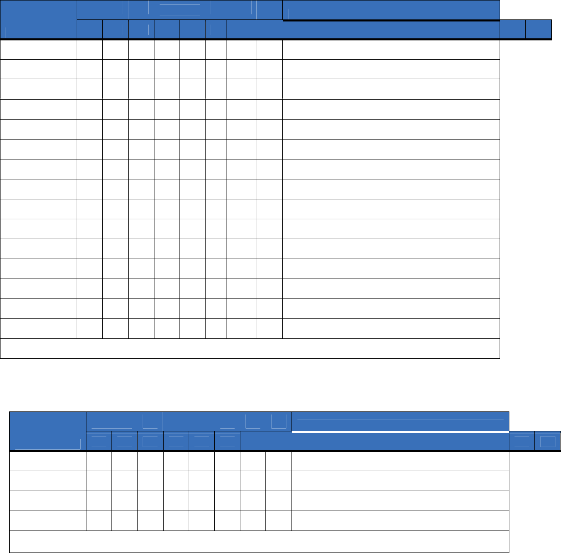
Location 12, Reporting events to
pa
ge
r
(Phone line is good)
Location 13, Reporting special events to pa
ge
r
(Phone line is good)
Table 31. Location 13 worksheet
Table 30. Location 12 worksheet
Partition
Description
Segment 1 2 3 4 5 6
7 8
1
Alarms
2
Open/close
3
Bypass
4
Zone trouble
5
Power trouble (AC fail or low battery)
6
Siren and telephone fault
7
Test reports
8
Program, download, and log full
9
Tampers
10
Short circuit and ground fault
11
Sensor lost
12
Sensor low battery
13
Expander trouble
14
Fail to communicate
15
Zone activity monitor
Partition
Description
Segment 1 2 3 4 5 6 7 8
1
Alarm restores
2
Telephone fault
3
Start download
4
Fail to communicate, data lost
5 to 8 Reserved for future
use.

Specifications
Operating power 12 VDC, typical (9 to 15 VDC) supplied from NX control panel or NX-320E power supply
Power consumption
Standby with service LEDs disabled 70 mA max.
Standby with service LEDs enabled 90 mA max.
Transmission burst (<1 second) 700 mA max.
Operating temperature 32 to 120°F (0 to 49°C)
Dimensions (W x H x D) 1.7 x 4.0 x 1.7 in. (45 x 102 x 45 mm)
Shipping weight 1 lb.
Support
This section offers technical support contacts in case you need assistance.
Contacting technical support
For assistance installing, operating, maintaining, and troubleshooting this product, refer to this document and
any other documentation provided. If you still have questions, you may contact technical support during
normal business hours (Monday through Friday, excluding holidays, between 8 a.m. and 8 p.m. Eastern Time)
at 888.987.5465 and press 2 at the prompt.
Index
A
address .................................................................................................... 3
C
conventio
ns.............................................................................................. 1
E
enrollment................................................................................................ 3
exit mode ..................................
............................................................... 8
F
factory default.......................................................................................... 8
I
installation .............................................................
.................................. 4
L
LED ..................................................................................................... 5, 6
location programming ............................................................................. 8
M
module address.........................................................................................3
mounting.................................................................................................. 4
P
preface .............................
......................................................................... 1
product
overview
................................................................................. 2
program mode...................................................................
....................... 8
programming ........................................................................................... 8
programming locations
location 0 ........................................................................................... 10
location 1 ........................................................................................... 10
location 10 ......................................................................................... 15
location 11 ......................................................................................... 15
location 12 ......................................................................................... 16
location 13 ......................................................................................... 16
location 2 ........................................................................................... 11
location 3 ........................................................................................... 11
location 4 ........................................................................................... 12
location 5 ........................................................................................... 12
location 6 ........................................................................................... 13
location 7 ........................................................................................... 13
location 8 ........................................................................................... 14
location 9 ........................................................................................... 14
programming worksheets
location 0 ........................................................................................... 17
location 1 ........................................................................................... 17
location 10 ......................................................................................... 22
location 11 ......................................................................................... 22
location 12 ......................................................................................... 23
location 13 ......................................................................................... 23
location 2 ........................................................................................... 18
location 3 ........................................................................................... 18
location 4 ........................................................................................... 19
location 5 ........................................................................................... 19
location 6 ........................................................................................... 20
location 7 ........................................................................................... 20
location 8 ........................................................................................... 21
location 9 ........................................................................................... 21
publication library ............................................................................. 25
S
safety terms and symbols ........................................................
................ 1
T
technical support ................................................................................... 25
troubleshooting...................................................................................... 25
W
web activation ....
..................................................................................... 2
wire gauge
............................................................................................... 5
wiring ....................................................
.................................................. 5